JP3967145B2 - Projector device - Google Patents
Projector device Download PDFInfo
- Publication number
- JP3967145B2 JP3967145B2 JP2002032734A JP2002032734A JP3967145B2 JP 3967145 B2 JP3967145 B2 JP 3967145B2 JP 2002032734 A JP2002032734 A JP 2002032734A JP 2002032734 A JP2002032734 A JP 2002032734A JP 3967145 B2 JP3967145 B2 JP 3967145B2
- Authority
- JP
- Japan
- Prior art keywords
- light
- wavelength
- light source
- solid
- green
- Prior art date
- Legal status (The legal status is an assumption and is not a legal conclusion. Google has not performed a legal analysis and makes no representation as to the accuracy of the status listed.)
- Expired - Fee Related
Links
Images


Landscapes
- Liquid Crystal (AREA)
- Projection Apparatus (AREA)
- Transforming Electric Information Into Light Information (AREA)
Description
【0001】
【発明の属する技術分野】
本発明は、青〜紫外光を可視光に変換して用いる可視光光源を有するプロジェクタ装置に関するものである。
【0002】
【従来の技術】
近年、液晶画面を用いた液晶表示装置が急速に普及しており、その液晶表示装置の1つとして液晶プロジェクタが知られている。液晶プロジェクタは、赤、緑、青の光の3原色に分解された映像を液晶パネル中に表示させ、その透過光をスクリーン上で所定の映像となるように重ね合わせることにより、スクリーン上に所定の映像を表示するものである。これに用いられる光源は、通常、数千ルーメン程度の光度のものが必要であり、通常、気体光源の一例であるメタルハイドロランプが光源として用いられている。
【0003】
【発明が解決しようとする課題】
ところが、メタルハイドロランプに代表される気体光源は、高い光度が得られるが、発光体が電極を有する真空管であるために、点光源にならないので、光の収束性が低い。また、メタルハイドロランプは、寿命が短く、発熱量、および、消費電力も大きいという問題がある。これに対し、特開平2−118624号公報では、プロジェクタ部と光源部とを分離した装置が提案されている。しかしながら、その装置は、プロジェクタ部においては小型化されているが、プロジェクタ装置全体としては、以前と同様に、大型で、かつ、発熱量および消費電力が大きい。
【0004】
本発明は、上述の問題に鑑みてなされたものであり、その目的は、光源光の収束性を高めることにより小型化されたプロジェクタ装置を提供することである。
【0005】
また、本発明のさらなる目的は、長寿命で、発熱量および消費電力が低減されたプロジェクタ装置を提供することである。
【0010】
【課題を解決するための手段】
本発明の第1の局面のプロジェクタ装置は、半導体レーザまたはLED( Light Emitting Diode )を含み、波長500nm以下の光を発する固体光源と、固体光源から発せられた発射光が照射され、発射光の波長が変換されて赤色光が出射される赤色用可視波長下方変換材料と、固体光源から発せられた発射光が照射され、発射光の波長が変換されて緑色光が出射される緑色用可視波長下方変換材料と、固体光源から発せられた発射光が照射され、発射光の波長が変換されて青色光が出射される青色用可視波長下方変換材料と、赤色光、緑色光、および、青色光の3色光を組合せて、任意の画像を作成する画像作成機構とを備えている。
【0011】
上記の構成によれば、固体光源を用いて光源光の収束性を高めることにより、光源光の収束性が低い気体光源を用いる場合に比較して、可視光光源装置を小型化することができる。
【0012】
本発明の第1の局面のプロジェクタ装置は、赤色用可視波長下方変換材料、緑色用可視波長下方変換材料および青色用可視波長下方変換材料のそれぞれが、光ファイバのコアに設けられている。
【0013】
上記の構成によれば、赤色光、緑色光および青色光のそれぞれを光ファイバにより伝送することができるため、プロジェクタ装置の設計の自由度を増大させることができる。
【0014】
本発明の第1の局面のプロジェクタ装置は、固体光源が、赤色用可視波長下方変換材料に光を発する赤色用固体光源、緑色用可視波長下方変換材料に光を発する緑色用固体光源および青色用可視波長下方変換材料に光を発する青色用固体光源とを含んでいてもよい。
【0015】
上記の構成によれば、半導体レーザまたはLED( Light Emitting Diode )を含み、波長500nm以下の光を発する固体光源をそれぞれ別個に制御することができる。
本発明の第1の局面のプロジェクタ装置は、固体光源が1つの固体光源であり、1つの固体光源から発せられた光を3つに分光する分光機構を備え、その分光機構により分光された3つの光それぞれが、赤色用可視波長下方変換材料、緑色用可視波長下方変換材料および青色用可視波長下方変換材料に1対1対応で照射されてもよい。
【0016】
上記の構成によれば、固体光源を1つに集約することができる。
本発明の第2の局面のプロジェクタ装置は、半導体レーザまたはLED( Light Emitting Diode )を含み、緑色の光の波長以下の波長の光を発する固体光源と、固体光源から発せられた発射光が照射され、発射光の波長が変換されて赤色光が出射される赤色用可視波長下方変換材料と、固体光源から発せられた発射光が照射され、発射光の波長が変換されて緑色光が出射される緑色用可視波長下方変換材料と、青色光を発する青色用の固体光源と、赤色光、緑色光、および、青色光の3色光を組合せて、任意の画像を作成する画像作成機構とを備えている。
前述の固体光源は、波長500nm以下の光を発してもよい。
【0017】
上記の構成によれば、光源光の収束性が低い気体光源を用いる場合に比較して、固体光源の光の収束性を高めることによりプロジェクタ装置を小型化することができる。
【0018】
本発明の第2の局面のプロジェクタ装置は、赤色用可視波長下方変換材料および緑色用可視波長下方変換材料のそれぞれが、光ファイバのコアに設けられている。
【0019】
上記の構成によれば赤色光および緑色光のそれぞれを光ファイバにより伝送することができるため、可視光光源装置の設計の自由度を増大させることができる。
【0021】
上記の構成によれば、半導体レーザを固体光源に用いることにより、従来のメタルハライドランプなどの気体光源に比較して、可視光光源装置を長寿命にし、かつ、可視光光源装置の発熱量および消費電力を低減することができる。
【0023】
上記の構成によれば、半導体レーザを固体光源に用いることにより、従来のメタルハライドランプなどの気体光源に比較して、プロジェクタ装置を長寿命にし、かつ、プロジェクタ装置の発熱量および消費電力を低減することができる。
【0024】
【発明の実施の形態】
以下、本発明の実施の形態を、図面を参照しながら説明する。
【0025】
(実施の形態1)
図1には、本実施の形態の可視光光源装置の概略構成が示されている。本実施の形態の可視光光源装置は、図1に示すように、励起用固体光源として青色の光を出射する半導体レーザ10と、その半導体レーザ10から出射された光を光ファイバに導くためのコリメートレンズ11と、可視波長となるように光の波長を変換する可視波長下方変換材料がドーピングされたコアを有する光ファイバ12と、励起用の半導体レーザ10から出射された光の波長より長波長の光のみを透過させる波長フィルタ13とを備えている。
【0026】
このような本実施の形態の可視光光源装置においては、半導体レーザ10から出射された光が、コリメートレンズ11により光ファイバ12に導かれる。また、光ファイバ12に導かれた光は、コアにドーピングされた可視波長下方変換材料を励起し、その励起された可視波長下方変換材料により可視光に波長変換されて、波長フィルタ13に対して光ファイバ12から出射される。なお、可視光に波長変換されない励起光は波長フィルタ13でカットされる。
【0027】
図2には、上記光ファイバを用いた液晶プロジェクタ装置の模式図が示されている。本実施の形態の液晶プロジェクタ装置は、波長405nmの半導体レーザ20と、半導体レーザ20から出射された光が透過するコリメートレンズ21とをそれぞれ3つ備えている。
【0028】
また、3つのコリメートレンズそれぞれを透過した光は、励起光を青色に変換する波長下方変換材料がドーピングされたコアを有する光ファイバ22、励起光を緑色に変換する波長下方変換材料がドーピングされたコアを有する光ファイバ23、および、励起光を赤色に変換する波長下方変換材料がドーピングされたコアを有する光ファイバ24のそれぞれに導入される。
【0029】
光ファイバ22,23,24それぞれの内部の波長下方変換材料により波長変換された光それぞれは、励起用半導体レーザ20から出射された光の波長より長波長の光を透過させる波長フィルタ25、光ファイバ22,23,24から出た光を液晶パネルに導くための集光レンズ26、液晶パネル27,28,29、および、投射用レンズ30それぞれを透過してスクリーン31に到達する。スクリーン31には、液晶パネル27,28,29において、適宜、赤色、緑色、青色の3原色が組み合わせられて、任意の画像が映し出される。
【0030】
本実施の形態の液晶プロジェクタの駆動電力は、100Wであり、現状のメタルハイドロランプを用いた液晶プロジェクタの駆動電力の1/10である。また、可視光光源装置の寿命は10000時間であり、液晶プロジェクタの大きさは従来に比べて1/3となり、液晶プロジェクタは、低消費電力、長寿命かつ小型化が実現されている。
【0031】
また、励起用半導体レーザ20の波長としては、405nmを用いたが、その波長はこれに限るものではなく、500nm以下の波長を有するレーザまたはLEDを用いれば、前述の効果を得ることができる。
【0032】
なお、半導体レーザ20から出射される励起光が500nmより長波長になると、青色の光を得ることができなくなるため、液晶表示装置においてフルカラーで画像を表示することができなくなる。
【0033】
また、励起用半導体レーザ20から出射されたレーザ光がコリメートレンズ21などで反射し、励起用半導体レーザ20に戻り光として入射するとノイズなどの問題が生じる可能性がある。そのため、レンズを傾けるなどの戻り光対策を行ない、出射光と戻り光との干渉によるノイズ対策を適宜行なう必要がある。
【0034】
また、本実施の形態での液晶プロフジェクタは、光の三原色を構成する赤、緑、青の三色を形成するために、それぞれの色に対応する3個の励起用半導体レーザを用いたが、1つまたは2つの励起用レーザを用いて、1つの励起用レーザから出射された励起光をハーフミラーなどで3つまたは2つの光に分光して、光の三原色を構成する赤、緑、青の三色を形成するための3つの光を作り出すものであってもよい。また、液晶プロフジェクタは、3個以上の励起用半導体レーザがアレイ状に構成されたものであってもよい。
【0035】
(実施の形態2)
図3には、本実施の形態の液晶プロジェクタ装置の模式図が示されている。本実施の形態の液晶プロジェクタは、波長365nmの青色光を出射する半導体レーザ40と、半導体レーザ40から出射された青色のレーザ光を所定の方向へ導くためのコリメートレンズ41と、コリメートレンズ41を透過した励起光を3つに分岐させる2つのハーフミラー42とコリメートレンズ41を透過した励起光を反射するミラー47とを備えている。
【0036】
その2つのハーフミラー42およびミラー47により反射された光それぞれは、励起光を青色に変換する波長下方変換蛍光体43、励起光を緑色に変換する波長下方変換蛍光体44、および、励起光を赤色に変換する波長下方変換蛍光体45に入射する。波長変換されて波長下方変換蛍光体43,44,45それぞれから出射された3つの光は、励起用の半導体レーザ40から出射された光以外の波長を透過させるノッチフィルタ46を透過する。
【0037】
3つの光のうち、左右両側の2つの光は、ミラー47により反射され、真中の1つの光は、そのまま、液晶パネル48,49,50それぞれに導かれる。液晶パネル48,49,50それぞれに透過した光は、ダイクロイックプリズム51を経て、投光用レンズ52からスクリーン53へ導かれる。スクリーン53には、液晶パネル48,49,50において、適宜、赤色、緑色、青色の3原色が組み合わせられて、任意の画像が映し出される。
【0038】
本実施の形態のプロジェクタの駆動電力は、75Wであり、現状のメタルハイドロランプを用いた液晶プロジェクタの駆動電力の1/4であった。また、光源の寿命は10000時間であり、液晶プロジェクタの大きさは従来に比べて1/5となり、液晶プロジェクタは、低消費電力、長寿命かつ小型化が実現されている。
【0039】
なお、本実施の形態の液晶プロジェクタは、励起用の半導体レーザの波長として365nmを用いたが、その波長はこれに限るものではなく、500nm以下の波長を有するレーザまたはLEDを用いてもよい。
【0040】
なお、半導体レーザ40から出射される励起光が500nmより長波長になると、青色の光を得ることができなくなるため、液晶表示装置においてフルカラーで画像を表示することができなくなる。
【0041】
また、本実施の形態の液晶プロジェクタでは、1個の励起用半導体レーザを用いたが、2個以上の励起用半導体レーザを用いても、同様に前述の効果を得ることができる。
【0042】
要するに、上記実施の形態1または2の液晶プロジェクタによれば、500nm以下の波長を有する固体光源を可視波長下方変換材料に照射して赤、緑、青の光の3原色を得ており、また、固体光源として半導体レーザまたは半導体LEDを用いているため、光源が点光源になるので、光の集束性が良く、液晶プロジェクタ装置の大きさを小さくすることができるとともに、長寿命で、発熱量、消費電力を低減することができる。
【0043】
(実施の形態3)
図4には、本実施の形態の液晶プロジェクタ装置の模式図が示されている。本実施の形態の液晶プロジェクタ装置は、波長460nmの青色光を出射する半導体LED60を1機、波長405nmの青色光を出射する半導体レーザ61を2機備えている。また、1機の半導体LEDから出射された光を導くコリメートレンズ63と、コリメートレンズ63を透過した光を反射する凹面鏡64とを備えている。
【0044】
また、2機の半導体レーザ61から出射された光それぞれを導く2つの光ファイバ62と、2つの光ファイバ62から出射された光それぞれが入射する励起光を緑色に変換する波長下方変換蛍光体65および励起光を赤色に変換する波長下方変換蛍光体66とを備えている。
【0045】
また、凹面鏡64で反射された励起光用の半導体レーザ61の波長より長波長の光を透過させる2つの波長フィルタ67と、コリメートレンズ63を透過した光を反射するミラー68とを備えている。また、波長フィルタ67を透過した光およびミラー68で反射された光が入射する液晶パネル69,70,71を備えている。
【0046】
また、液晶パネル69,70,71それぞれを出射した光は、ダイクロイックプリズム72を経て、投光用レンズ73からスクリーン74へ導かれる。スクリーン74には、液晶パネル69,70,71において、適宜、赤色、緑色、青色の3原色が組み合わせられて、任意の画像が映し出される。
【0047】
本実施の形態のプロジェクタの駆動電力は、80Wであり、現状のメタルハイドロランプを用いた液晶プロジェクタの駆動電力の1/4である。また、可視光光源の寿命は10000時間であり、液晶プロジェクタの大きさは従来に比べて1/3となり、液晶プロジェクタは、低消費電力、長寿命かつ小型化が実現されている。
【0048】
なお、励起用半導体レーザの波長としては405nmを用いたが、その波長はこれに限るものではなく、500nm以下の波長を有する半導体レーザまたは半導体LEDであれば、同様に前述の効果を得ることができる。
【0049】
なお、励起光が500nmより長波長になると、青色の光を得ることができなくなるため、液晶プロジェクタにおいてフルカラーで画像を表示することができなくなる。
【0050】
また、本実施の形態の液晶プロジェクタでは、2個の励起用の半導体レーザを用いたが、1個のレーザから発せられた光を3以上に分岐させて用いても同様に前述の効果を得ることができ、また、3個以上の励起用の半導体レーザを用いても、同様に前述の効果を得ることができる。
【0051】
(実施の形態4)
図5には、本実施の形態の液晶プロジェクタ装置を模式図が示されている。本実施の形態の液晶プロジェクタ装置は、波長405nmの青色光を出射する励起用半導体レーザ80と、半導体レーザ80から出射された青色光を導くコリメートレンズ81と、コリメートレンズ81を透過した光の色を分離するためのカラーホイール82とを備えている。
【0052】
また、カラーホイール82を経た励起用半導体レーザ80から出射された光のうち所定の波長の光を透過させるノッチフィルタ86と、ノッチフィルタ86を透過した光を集める集光レンズ83と、集光レンズ83を透過した光を反射するDMD(Digital Micromirror Device)84と、DMD84により反射された光が投影されるスクリーン85とを備えている。
【0053】
また、図左側にカラーホイール82が拡大図により示されており、カラーホイール82には、励起光を青色に変換する波長下方変換蛍光体90と、励起光を緑色に変換する波長下方変換蛍光体91と、励起光を赤色に変換する波長下方変換蛍光体92とが組込まれており、このカラーホイール82が回転することにより波長下方変換蛍光体90,91,92それぞれにおいて、励起用の半導体レーザ80から出射されたレーザ光は、赤、緑、青のそれぞれに変換されて、出射される。そして、カラーホイールの回転の態様により、赤、青、緑の3色が組合せられて任意の色画像がスクリーン85に表示される。
【0054】
本実施の形態のプロジェクタ装置の駆動電力は、80Wであり、現状のメタルハイドロランプを用いたプロジェクタの1/4である。また、光源の寿命も10000時間で、装置の大きさも従来に比べて1/3となる。その結果、本実施の形態のプロジェクタ装置によれば、低消費電力、長寿命および小型化を実現することができる。
【0055】
なお、励起用半導体レーザは405nmを用いたが、波長はこれに限るものではなく、500nm以下の波長を有するレーザ、LEDを用いればよい。励起光が500nmより長波長になると、青色の光を得ることができなくなるため、液晶プロジェクタにおいてフルカラーで画像を表示することができなくなる。
【0056】
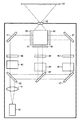
(実施の形態5)
図6には、本実施の形態の液晶プロジェクタ装置の模式図が示されている。本実施の形態の液晶プロジェクタ装置は、波長405nmの青色光を出射する半導体レーザ100と、半導体レーザ100から出射された光が透過するコリメートレンズ101と、コリメートレンズ101を透過した光を分岐させる複数のハーフミラー102とコリメートレンズ101を透過した光を反射するミラー114とを備えている。
【0057】
また、複数のハーフミラー102により分岐された光およびミラー114により反射された光それぞれは、励起光を青色に変換する波長下方変換蛍光体103、励起光を緑色に変換する波長下方変換蛍光体104、および、励起光を赤色に変換する波長下方変換蛍光体105それぞれに入射する。波長下方変換蛍光体103,104,105により波長変換された光それぞれは、反射型液晶パネル106,107,108により反射されて、偏光ビームスプリッタ109,110,111、および、ダイクロイックプリズム112を経て、スクリーン113に投影される。スクリーン113には、液晶パネル106,107,108において、適宜、赤色、緑色、青色の3原色が組み合わせられて、任意の画像が映し出される。
【0058】
本実施の形態の液晶プロジェクタ装置の駆動電力は、100Wであり、現状のメタルハイドロランプを用いた液晶プロジェクタの1/3である。また、光源の寿命も10000時間で、装置の大きさも従来に比べて1/3となり、低消費電力、長寿命および小型化を実現することができる。
【0059】
なお、反射型の液晶パネル106,107,108の代わりにDMDを用いることも可能である。その際は、109,110,111の偏光ビームスプリッタを全反射プリズムに置換える必要がある。
【0060】
(実施の形態6)
図7には、本実施の形態の液晶プロジェクタ装置の模式図が示されている。本実施の形態の液晶プロジェクタ装置は、波長455nmの青色光を出射する半導体レーザ120を1機、波長395nmの青色光を出射する半導体レーザ121を2機備えている。また、半導体レーザ120,121それぞれから出射された光は、コリメートレンズ122を透過して、3つの光ファイバに導かれる。
【0061】
この3つの光ファイバは、通常の光ファイバ123と、励起光を緑色に変換する波長下方変換材料がドーピングされたコアを有する光ファイバ124と、励起光を赤色に変換する波長下方変換材料がドーピングされたコアを有する光ファイバ133とから構成されている。
【0062】
光ファイバ123に入射した光はそのまま出射し、また、光ファイバ124,133に入射した波長変換されて出射された光は、励起用半導体レーザ124,133の波長より長波長の光を透過させる波長フィルタ126を透過して、液晶パネルに導く集光レンズ125に導かれる。集光レンズ125を透過した光は、液晶パネル127,128,129、ダイクロイックプリズム130、投光用レンズ131を介して、スクリーン132へ投影される。スクリーン132には、液晶パネル127,128,129において、適宜、赤色、緑色、青色の3原色が組み合わせられて、任意の画像が映し出される。
【0063】
本実施の形態の液晶プロジェクタ装置の駆動電力は、120Wであり、現状のメタルハイドロランプを用いた液晶プロジェクタの1/3である。また、光源の寿命は10000時間であり、液晶プロジェクタ装置の大きさは従来に比べて1/3となる。したかって、本実施の形態の液晶プロジェクタ装置によれば、低消費電力、長寿命および小型化が実現されている。
【0064】
なお、青色光源には半導体レーザを用いたが、光源はこれに限るものではなく、半導体LEDでもよい。
【0065】
また、励起用半導体レーザは395nmを用いたが、波長はこれに限るものではなく、500nm以下の波長を有するレーザ、LEDを用いればよい。半導体レーザ120,121から出射される励起光が500nmより長波長になると、青色の光を得ることができなくなるため、液晶プロジェクタにおいてフルカラーで画像を表示することができなくなる。
【0066】
上記実施の形態1〜6のプロジェクタにおいては、青色の光を発する固体光源を用いたが、赤色、緑色、透明色等何色を用いてもよい。
【0067】
また、上記実施の形態1〜6のプロジェクタにおいては、波長下方変換材料は、複数色を変換するために複数種類用いた場合を示したが、赤色、緑色、青色のうちいずれか1色を変換するもの1種類を用いてもよい。
【0068】
なお、今回開示された実施の形態はすべての点で例示であって制限的なものではないと考えられるべきである。本発明の範囲は上記した説明ではなく特許請求の範囲によって示され、特許請求の範囲と均等の意味および範囲内でのすべての変更が含まれることが意図される。
【0069】
【発明の効果】
本発明によれば、固体光源を用いて光源光の収束性を高めることにより、光源光の収束性が低い気体光源を用いる場合に比較して、プロジェクタ装置を小型化することができる。
【図面の簡単な説明】
【図1】 実施の形態1の可視光光源装置を示す模式図である。
【図2】 実施の形態1の液晶プロジェクタ装置を示す模式図である。
【図3】 実施の形態2の液晶プロジェクタ装置を示す模式図である。
【図4】 実施の形態3の液晶プロジェクタ装置を示す模式図である。
【図5】 実施の形態4の液晶プロジェクタ装置を示す模式図である。
【図6】 実施の形態5の液晶プロジェクタ装置を示す模式図である。
【図7】 実施の形態6の液晶プロジェクタ装置を示す模式図である。
【符号の説明】
10 半導体レーザ、11 コリメートレンズ、12 可視波長下方変換材料がドーピングされたコアを有する光ファイバ、13 波長フィルタ、20 半導体レーザ、21 コリメートレンズ、22 励起光を青色に変換する波長下方変換材料がドーピングされたコアを有する光ファイバ、23 励起光を緑色に変換する波長下方変換材料がドーピングされたコアを有する光ファイバ、24 励起光を赤色に変換する波長下方変換材料がドーピングされたコアを有する光ファイバ、25 波長フィルタ、26 集光レンズ、27,28,29 液晶パネル、30 投射用レンズ、31 スクリーン、40 半導体レーザ、41 コリメートレンズ、42 ハーフミラー、43 励起光を青色に変換する波長下方変換蛍光体、44 励起光を緑色に変換する波長下方変換蛍光体、45 励起光を赤色に変換する波長下方変換蛍光体、46 ノッチフィルタ、47 ミラー、48,49,50 液晶パネル、51 ダイクロイックプリズム、52 投光用レンズ、53 スクリーン、60 LED、61 半導体レーザ、62 光ファイバ、63 コリメートレンズ、64 凹面鏡、65 励起光を緑色に変換する波長下方変換蛍光体、66 励起光を赤色に変換する波長下方変換蛍光体、67 波長フィルタ、68 ミラー、69,70,71 液晶パネル、72 ダイクロイックプリズム、73 投光用レンズ、74 スクリーン、80 半導体レーザ、81 コリメートレンズ、82 カラーホイール、83 集光レンズ、84 DMD、85 スクリーン、90 励起光を青色に変換する波長下方変換蛍光体、91 励起光を緑色に変換する波長下方変換蛍光体、92 励起光を赤色に変換する波長下方変換蛍光体、100 半導体レーザ、101 コリメートレンズ、102 ハーフミラー、103 励起光を青色に変換する波長下方変換蛍光体、104 励起光を緑色に変換する波長下方変換蛍光体、105 励起光を赤色に変換する波長下方変換蛍光体、106,107,108 反射型液晶パネル、109,110,111 偏光ビームスプリッタ、112 ダイクロイックプリズム、113 スクリーン、114 ミラー、120 半導体レーザ、121 半導体レーザ、122 コリメートレンズ、123 光ファイバ、124 励起光を緑色に変換する波長下方変換材料がドーピングされたコアを有する光ファイバ、125 集光レンズ、126 波長フィルタ、127,128,129 液晶パネル、130 ダイクロイックプリズム、131 投光用レンズ、132 スクリーン、133 励起光を赤色に変換する波長下方変換材料がドーピングされたコアを有する光ファイバ。[0001]
BACKGROUND OF THE INVENTION
The present invention relates to a projector device having a visible light source that converts blue to ultraviolet light into visible light.
[0002]
[Prior art]
In recent years, a liquid crystal display device using a liquid crystal screen has been rapidly spread, and a liquid crystal projector is known as one of the liquid crystal display devices. A liquid crystal projector displays an image separated into three primary colors of red, green, and blue on a liquid crystal panel, and superimposes the transmitted light so that a predetermined image is displayed on the screen. The video is displayed. The light source used for this is usually required to have a luminous intensity of about several thousand lumens, and a metal hydrolamp, which is an example of a gas light source, is usually used as the light source.
[0003]
[Problems to be solved by the invention]
However, a gas light source typified by a metal hydrolamp can obtain a high luminous intensity, but since the light emitter is a vacuum tube having electrodes, it does not become a point light source and therefore has low light convergence. In addition, the metal hydrolamp has a problem that it has a short life, a large amount of heat generation, and a large amount of power consumption. On the other hand, Japanese Patent Laid-Open No. 2-118624 proposes an apparatus in which a projector unit and a light source unit are separated. However, although the apparatus is downsized in the projector unit, the projector apparatus as a whole is large in size and has a large amount of heat generation and power consumption as before.
[0004]
The present invention has been made in view of the above-described problems, and an object thereof is to provide a projector device that is miniaturized by improving the convergence of light source light.
[0005]
A further object of the present invention is to provide a projector device that has a long life and has reduced heat generation and power consumption.
[0010]
[Means for Solving the Problems]
A projector device according to a first aspect of the present invention includes:Semiconductor laser or LED ( Light Emitting Diode ) Including light with a wavelength of 500 nm or lessA solid-state light source that emits light, irradiation light emitted from the solid-state light source is irradiated, the wavelength of the emitted light is converted, and red light is emitted, and red light is emitted, and emission light emitted from the solid-state light source is irradiated The green visible wavelength down-converting material that emits green light by converting the wavelength of the emitted light and the emitted light emitted from the solid light source are irradiated, the wavelength of the emitted light is converted, and blue light is emitted. A visible wavelength downward conversion material for blue, and an image creation mechanism for creating an arbitrary image by combining three colors of light of red light, green light, and blue light.
[0011]
According to said structure, the visible light source device can be reduced in size compared with the case where the gas light source with the low convergence property of light source light is used by improving the convergence property of light source light using a solid light source. .
[0012]
The projector device according to the first aspect of the present invention includes a visible wavelength downward conversion material for red, a visible wavelength downward conversion material for green, and a visible wavelength downward conversion material for blue.RespectivelyIs provided in the core of the optical fiber.
[0013]
According to the above configuration, red light, green light and blue lightRespectivelyCan be transmitted by an optical fiber, so that the degree of freedom in designing the projector device can be increased.
[0014]
First of the present invention1The solid state light source emits light to the visible wavelength down-converting material for red, the solid-state light source for green emitting the light to the visible-wavelength down converting material for green, and the visible wavelength down-converting material for blue And a solid light source for blue which emits light.
[0015]
According to the above configuration,Semiconductor laser or LED ( Light Emitting Diode ) And emits light with a wavelength of 500 nm or lessEach solid state light source can be controlled separately.
In the projector device according to the first aspect of the present invention, the solid-state light source is a single solid-state light source, and includes a spectroscopic mechanism that divides light emitted from one solid-state light source into three. Each of the two lights may be applied to the red visible wavelength down-converting material, the green visible wavelength down-converting material, and the blue visible wavelength down-converting material in a one-to-one correspondence.
[0016]
According to said structure, a solid light source can be collected into one.
A projector device according to a second aspect of the present invention provides:Semiconductor laser or LED ( Light Emitting Diode ) Including and below the wavelength of green lightA solid-state light source that emits light, a visible wavelength down-converting material for red that emits red light by being irradiated with emission light emitted from the solid-state light source, and emission light emitted from the solid-state light source , A visible wavelength down-converting material for green that emits green light by converting the wavelength of the emitted light, a solid light source for blue that emits blue light, red light, green light, and blue light 3 And an image creation mechanism for creating an arbitrary image by combining color lights.
The aforementioned solid light source may emit light having a wavelength of 500 nm or less.
[0017]
According to said structure, compared with the case where the gas light source with the low convergence property of light source light is used, a projector apparatus can be reduced in size by improving the light convergence property of a solid light source.
[0018]
The projector device according to the second aspect of the present invention includes a visible wavelength down-converting material for red and a visible wavelength down-converting material for green.RespectivelyIs provided in the core of the optical fiber.
[0019]
According to the above configuration, red light and green lightEach ofTherefore, the degree of freedom in designing the visible light source device can be increased.
[0021]
According to the above configuration, by using a semiconductor laser as a solid-state light source, the lifetime of the visible light source device is longer than that of a gas light source such as a conventional metal halide lamp, and the amount of heat generated and consumed by the visible light source device. Electric power can be reduced.
[0023]
According to the above configuration, by using a semiconductor laser as a solid-state light source, the projector device has a longer life than a conventional gas light source such as a metal halide lamp, and the heat generation amount and power consumption of the projector device are reduced. be able to.
[0024]
DETAILED DESCRIPTION OF THE INVENTION
Hereinafter, embodiments of the present invention will be described with reference to the drawings.
[0025]
(Embodiment 1)
FIG. 1 shows a schematic configuration of the visible light source device of the present embodiment. As shown in FIG. 1, the visible light source device of the present embodiment includes a
[0026]
In such a visible light source device of this embodiment, light emitted from the
[0027]
FIG. 2 shows a schematic diagram of a liquid crystal projector apparatus using the optical fiber. The liquid crystal projector device according to the present embodiment includes three
[0028]
The light transmitted through each of the three collimating lenses is doped with an
[0029]
A
[0030]
The driving power of the liquid crystal projector of the present embodiment is 100 W, which is 1/10 of the driving power of a liquid crystal projector using a current metal hydrolamp. In addition, the lifetime of the visible light source device is 10,000 hours, and the size of the liquid crystal projector is 1/3 of the conventional size. The liquid crystal projector is realized with low power consumption, long life, and downsizing.
[0031]
The wavelength of the
[0032]
If the excitation light emitted from the
[0033]
Further, if the laser light emitted from the pumping
[0034]
In addition, the liquid crystal projector in this embodiment uses three pumping semiconductor lasers corresponding to the respective colors in order to form the three colors of red, green, and blue constituting the three primary colors of light. Using one or two excitation lasers, the excitation light emitted from one excitation laser is split into three or two lights by a half mirror or the like, and red, green, and light constituting the three primary colors of light, It may be one that creates three lights to form the three colors of blue. The liquid crystal projector may be an array of three or more excitation semiconductor lasers.
[0035]
(Embodiment 2)
FIG. 3 shows a schematic diagram of the liquid crystal projector device of the present embodiment. The liquid crystal projector of the present embodiment includes a
[0036]
Each of the light reflected by the two half mirrors 42 and 47 includes a wavelength down-converting
[0037]
Of the three lights, the two lights on the left and right sides are reflected by the
[0038]
The driving power of the projector according to the present embodiment is 75 W, which is 1/4 of the driving power of a liquid crystal projector using a current metal hydrolamp. In addition, the life of the light source is 10,000 hours, and the size of the liquid crystal projector is 1/5 of the conventional size, and the liquid crystal projector realizes low power consumption, long life, and miniaturization.
[0039]
In the liquid crystal projector according to the present embodiment, 365 nm is used as the wavelength of the semiconductor laser for excitation, but the wavelength is not limited to this, and a laser or LED having a wavelength of 500 nm or less may be used.
[0040]
Note that when the excitation light emitted from the
[0041]
Further, in the liquid crystal projector of the present embodiment, one excitation semiconductor laser is used, but the above-described effects can be similarly obtained even when two or more excitation semiconductor lasers are used.
[0042]
In short, according to the liquid crystal projector of the first or second embodiment, the three primary colors of red, green, and blue light are obtained by irradiating the visible light wavelength down-converting material with a solid light source having a wavelength of 500 nm or less, and Since a semiconductor laser or semiconductor LED is used as the solid light source, the light source becomes a point light source, so that the light focusing property is good, the size of the liquid crystal projector device can be reduced, the life is long, and the heat generation amount , Power consumption can be reduced.
[0043]
(Embodiment 3)
FIG. 4 shows a schematic diagram of the liquid crystal projector device of the present embodiment. The liquid crystal projector device of this embodiment includes one
[0044]
Also, two
[0045]
Further, two
[0046]
The light emitted from the
[0047]
The drive power of the projector according to the present embodiment is 80 W, which is ¼ of the drive power of a liquid crystal projector using a current metal hydrolamp. In addition, the lifetime of the visible light source is 10,000 hours, and the size of the liquid crystal projector is 1/3 of the conventional size, and the liquid crystal projector has realized low power consumption, long life, and downsizing.
[0048]
In addition, although 405 nm was used as the wavelength of the semiconductor laser for excitation, the wavelength is not limited to this, and if the semiconductor laser or the semiconductor LED has a wavelength of 500 nm or less, the above-described effects can be obtained in the same manner. it can.
[0049]
If the excitation light has a wavelength longer than 500 nm, blue light cannot be obtained, so that a full color image cannot be displayed on the liquid crystal projector.
[0050]
Further, in the liquid crystal projector of the present embodiment, two pumping semiconductor lasers are used, but the above-described effect can be obtained in the same manner even if light emitted from one laser is branched into three or more. Even if three or more semiconductor lasers for excitation are used, the above-described effects can be obtained similarly.
[0051]
(Embodiment 4)
FIG. 5 shows a schematic diagram of the liquid crystal projector device of the present embodiment. The liquid crystal projector device of the present embodiment includes an
[0052]
In addition, a
[0053]
Further, a
[0054]
The driving power of the projector device according to the present embodiment is 80 W, which is ¼ that of a projector using a current metal hydrolamp. Further, the lifetime of the light source is 10,000 hours, and the size of the apparatus is also reduced to 1/3 compared with the conventional one. As a result, according to the projector device of the present embodiment, low power consumption, long life, and downsizing can be realized.
[0055]
In addition, although 405 nm was used for the excitation semiconductor laser, the wavelength is not limited to this, and a laser or LED having a wavelength of 500 nm or less may be used. When the excitation light has a wavelength longer than 500 nm, blue light cannot be obtained, and thus a full color image cannot be displayed in the liquid crystal projector.
[0056]
(Embodiment 5)
FIG. 6 is a schematic diagram of the liquid crystal projector device of the present embodiment. The liquid crystal projector device of the present embodiment includes a
[0057]
Further, each of the light branched by the plurality of half mirrors 102 and the light reflected by the
[0058]
The driving power of the liquid crystal projector device of the present embodiment is 100 W, which is 1/3 that of a liquid crystal projector using a current metal hydrolamp. In addition, the life of the light source is 10,000 hours, and the size of the device is 1/3 of that of the conventional device, so that low power consumption, long life, and downsizing can be realized.
[0059]
It is also possible to use DMD instead of the reflective
[0060]
(Embodiment 6)
FIG. 7 shows a schematic diagram of the liquid crystal projector device of the present embodiment. The liquid crystal projector according to the present embodiment includes one
[0061]
These three optical fibers are doped with a normal
[0062]
The light incident on the
[0063]
The driving power of the liquid crystal projector device of the present embodiment is 120 W, which is 1/3 that of a liquid crystal projector using a current metal hydrolamp. Moreover, the lifetime of the light source is 10,000 hours, and the size of the liquid crystal projector device is 1/3 of the conventional size. Therefore, according to the liquid crystal projector device of the present embodiment, low power consumption, long life, and miniaturization are realized.
[0064]
Although a semiconductor laser is used for the blue light source, the light source is not limited to this, and a semiconductor LED may be used.
[0065]
Further, although the excitation semiconductor laser uses 395 nm, the wavelength is not limited to this, and a laser or LED having a wavelength of 500 nm or less may be used. When the excitation light emitted from the
[0066]
In the projectors of the first to sixth embodiments, a solid light source that emits blue light is used. However, any color such as red, green, or transparent color may be used.
[0067]
Further, in the projectors of the first to sixth embodiments, the case where a plurality of types of wavelength down-converting materials are used for converting a plurality of colors has been shown, but any one of red, green, and blue is converted. One type may be used.
[0068]
The embodiment disclosed this time should be considered as illustrative in all points and not restrictive. The scope of the present invention is defined by the terms of the claims, rather than the description above, and is intended to include any modifications within the scope and meaning equivalent to the terms of the claims.
[0069]
【The invention's effect】
According to the present invention, the projector device can be downsized by using a solid light source to improve the convergence of the light source light, as compared with the case where a gas light source having a low light source light convergence is used.
[Brief description of the drawings]
FIG. 1 is a schematic diagram illustrating a visible light source device according to a first embodiment.
FIG. 2 is a schematic diagram showing the liquid crystal projector device of the first embodiment.
FIG. 3 is a schematic diagram illustrating a liquid crystal projector device according to a second embodiment.
FIG. 4 is a schematic diagram illustrating a liquid crystal projector device according to a third embodiment.
FIG. 5 is a schematic diagram showing a liquid crystal projector device according to a fourth embodiment.
FIG. 6 is a schematic diagram showing a liquid crystal projector device according to a fifth embodiment.
FIG. 7 is a schematic diagram showing a liquid crystal projector device according to a sixth embodiment.
[Explanation of symbols]
DESCRIPTION OF SYMBOLS 10 Semiconductor laser, 11 Collimating lens, 12 Optical fiber which has core doped with visible wavelength down conversion material, 13 Wavelength filter, 20 Semiconductor laser, 21 Collimating lens, 22 Doping wavelength down conversion material which converts excitation light into blue 23, an optical fiber having a core doped with a wavelength down-converting material that converts excitation light into green, and 24 an optical fiber having a core doped with a wavelength down-converting material that converts excitation light into red Fiber, 25 wavelength filter, 26 Condensing lens, 27, 28, 29 Liquid crystal panel, 30 Projection lens, 31 Screen, 40 Semiconductor laser, 41 Collimating lens, 42 Half mirror, 43 Down wavelength conversion that converts excitation light into blue Phosphor, 44 Converts excitation light to green Wavelength down-conversion phosphor, 45 Wavelength down-conversion phosphor that converts excitation light to red, 46 Notch filter, 47 Mirror, 48, 49, 50 Liquid crystal panel, 51 Dichroic prism, 52 Projection lens, 53 Screen, 60 LED , 61 Semiconductor laser, 62 optical fiber, 63 collimating lens, 64 concave mirror, 65 wavelength down-converting phosphor that converts excitation light to green, 66 wavelength down-conversion phosphor that converts excitation light to red, 67 wavelength filter, 68 mirror 69, 70, 71 LCD panel, 72 Dichroic prism, 73 Projection lens, 74 screen, 80 Semiconductor laser, 81 Collimate lens, 82 Color wheel, 83 Condensing lens, 84 DMD, 85 screen, 90 Excitation light blue Wavelength down-converting phosphor, which converts to 91 wavelength down-converting phosphor that converts excitation light into green, 92 wavelength down-conversion phosphor that converts excitation light into red, 100 semiconductor laser, 101 collimating lens, 102 half mirror, 103 wavelength below that converts excitation light into blue Conversion phosphor, 104 Wavelength down-conversion phosphor that converts excitation light into green, 105 Wavelength down-conversion phosphor that converts excitation light into red, 106, 107, 108 Reflective liquid crystal panel, 109, 110, 111 Polarizing beam splitter 112 dichroic prism, 113 screen, 114 mirror, 120 semiconductor laser, 121 semiconductor laser, 122 collimating lens, 123 optical fiber, 124 optical fiber having a core doped with a wavelength down-converting material that converts excitation light into green, 125 Condenser lens, 126 waves Long filter, 127, 128, 129 liquid crystal panel, 130 dichroic prism, 131 projector lens, 132 screen, 133 Optical fiber having a core doped with a wavelength down-converting material that converts excitation light into red.
Claims (5)
該固体光源から発せられた発射光が照射され、該発射光の波長が変換されて赤色光が出射される赤色用可視波長下方変換材料と、
前記固体光源から発せられた発射光が照射され、該発射光の波長が変換されて緑色光が出射される緑色用可視波長下方変換材料と、
前記固体光源から発せられた発射光が照射され、該発射光の波長が変換されて青色光が出射される青色用可視波長下方変換材料と、
前記赤色光、前記緑色光、および、前記青色光の3色光を組合せて、任意の画像を作成する画像作成機構とを備え、
前記赤色用可視波長下方変換材料、前記緑色用可視波長下方変換材料および前記青色用可視波長下方変換材料のそれぞれが、光ファイバのコアに設けられている、プロジェクタ装置。A solid-state light source including a semiconductor laser or an LED (Light Emitting Diode) and emitting light having a wavelength of 500 nm or less;
A visible wavelength downward conversion material for red that is irradiated with emission light emitted from the solid-state light source, the wavelength of the emission light is converted, and red light is emitted;
Visible wavelength downward conversion material for green that is irradiated with emission light emitted from the solid light source, the wavelength of the emission light is converted, and green light is emitted;
A visible wavelength downward conversion material for blue that is irradiated with emission light emitted from the solid light source, the wavelength of the emission light is converted, and blue light is emitted;
An image creation mechanism that creates an arbitrary image by combining the red light, the green light, and the blue light;
The red visible wavelength down conversion material, each of the green visible wavelength down conversion material and the blue visible wavelength down conversion material is provided in the core of the optical fiber, the projector device.
該1つの固体光源から発せられた光を3つに分光する分光機構を備え、
該分光機構により分光された3つの光それぞれが、前記赤色用可視波長下方変換材料、前記緑色用可視波長下方変換材料および前記青色用可視波長下方変換材料に1対1対応で照射される、請求項1に記載のプロジェクタ装置。The solid state light source is one solid state light source;
A spectroscopic mechanism for splitting light emitted from the one solid-state light source into three;
Each of the three lights dispersed by the spectroscopic mechanism is irradiated in a one-to-one correspondence with the red visible wavelength down-converting material, the green visible wavelength down-converting material, and the blue visible wavelength down-converting material. Item 2. The projector device according to Item 1.
該固体光源から発せられた発射光が照射され、該発射光の波長が変換されて赤色光が出射される赤色用可視波長下方変換材料と、
前記固体光源から発せられた発射光が照射され、該発射光の波長が変換されて緑色光が出射される緑色用可視波長下方変換材料と、
青色光を発する青色用の固体光源と、
前記赤色光、前記緑色光、および、前記青色光の3色光を組合せて、任意の画像を作成する画像作成機構とを備え、
前記赤色用可視波長下方変換材料および前記緑色用可視波長下方変換材料のそれぞれが、光ファイバのコアに設けられている、プロジェクタ装置。A solid-state light source that includes a semiconductor laser or LED (Light Emitting Diode) and emits light having a wavelength equal to or less than the wavelength of green light;
A visible wavelength downward conversion material for red that is irradiated with emission light emitted from the solid-state light source, the wavelength of the emission light is converted, and red light is emitted;
Visible wavelength downward conversion material for green that is irradiated with emission light emitted from the solid light source, the wavelength of the emission light is converted, and green light is emitted;
A solid light source for blue light emitting blue light;
An image creation mechanism that creates an arbitrary image by combining the red light, the green light, and the blue light;
The projector device in which each of the visible wavelength down-converting material for red and the visible wavelength down-converting material for green is provided in an optical fiber core.
Priority Applications (1)
| Application Number | Priority Date | Filing Date | Title |
|---|---|---|---|
| JP2002032734A JP3967145B2 (en) | 2002-02-08 | 2002-02-08 | Projector device |
Applications Claiming Priority (1)
| Application Number | Priority Date | Filing Date | Title |
|---|---|---|---|
| JP2002032734A JP3967145B2 (en) | 2002-02-08 | 2002-02-08 | Projector device |
Publications (3)
| Publication Number | Publication Date |
|---|---|
| JP2003233123A JP2003233123A (en) | 2003-08-22 |
| JP2003233123A5 JP2003233123A5 (en) | 2005-05-26 |
| JP3967145B2 true JP3967145B2 (en) | 2007-08-29 |
Family
ID=27775765
Family Applications (1)
| Application Number | Title | Priority Date | Filing Date |
|---|---|---|---|
| JP2002032734A Expired - Fee Related JP3967145B2 (en) | 2002-02-08 | 2002-02-08 | Projector device |
Country Status (1)
| Country | Link |
|---|---|
| JP (1) | JP3967145B2 (en) |
Cited By (1)
| Publication number | Priority date | Publication date | Assignee | Title |
|---|---|---|---|---|
| WO2011026005A2 (en) * | 2009-08-31 | 2011-03-03 | 3M Innovative Properties Company | Projection and display system |
Families Citing this family (25)
| Publication number | Priority date | Publication date | Assignee | Title |
|---|---|---|---|---|
| JP2006119440A (en) * | 2004-10-22 | 2006-05-11 | Olympus Corp | Surface sequential illuminating apparatus and image projecting apparatus |
| WO2006049262A1 (en) * | 2004-11-08 | 2006-05-11 | Matsushita Electric Industrial Co., Ltd. | Video projector using coherent light source |
| US7188953B2 (en) * | 2005-05-03 | 2007-03-13 | Eastman Kodak Company | Display apparatus using LCD panel |
| JP4581946B2 (en) | 2005-09-29 | 2010-11-17 | セイコーエプソン株式会社 | Image display device |
| JP5019747B2 (en) * | 2005-12-28 | 2012-09-05 | オリンパス株式会社 | projector |
| JP2007178766A (en) * | 2005-12-28 | 2007-07-12 | Olympus Corp | Projector |
| US8908740B2 (en) | 2006-02-14 | 2014-12-09 | Nichia Corporation | Light emitting device |
| JP4678556B2 (en) * | 2009-03-17 | 2011-04-27 | カシオ計算機株式会社 | Light emitting device, light source device, and projector using the light source device |
| JP4697559B2 (en) | 2009-03-27 | 2011-06-08 | カシオ計算機株式会社 | Light source device and projector |
| JP5327529B2 (en) * | 2009-04-22 | 2013-10-30 | カシオ計算機株式会社 | Light source device and projector |
| JP4711156B2 (en) | 2009-06-30 | 2011-06-29 | カシオ計算機株式会社 | Light source device and projector |
| JP4742349B2 (en) * | 2009-06-30 | 2011-08-10 | カシオ計算機株式会社 | Light source device and projector |
| JP5625287B2 (en) * | 2009-08-21 | 2014-11-19 | カシオ計算機株式会社 | Light source device, projection device, projection method and program |
| JP5500339B2 (en) * | 2009-09-29 | 2014-05-21 | カシオ計算機株式会社 | Light source device and projector |
| JP5428078B2 (en) * | 2009-12-21 | 2014-02-26 | カシオ計算機株式会社 | Light source device and projector |
| JP2011133782A (en) * | 2009-12-25 | 2011-07-07 | Casio Computer Co Ltd | Light source unit and projector |
| JP5440864B2 (en) * | 2010-03-30 | 2014-03-12 | カシオ計算機株式会社 | Light emitting unit and projector |
| US20130221826A1 (en) * | 2010-09-21 | 2013-08-29 | Nec Corporation | Phosphor-coated light-emitting device |
| JP2012141411A (en) * | 2010-12-28 | 2012-07-26 | Jvc Kenwood Corp | Light source device |
| JP5413613B2 (en) * | 2011-02-04 | 2014-02-12 | カシオ計算機株式会社 | LIGHT SOURCE DEVICE, ITS CONTROL METHOD, AND PROJECTOR |
| TWI427397B (en) * | 2011-03-23 | 2014-02-21 | Delta Electronics Inc | Illumination system |
| JP5252053B2 (en) * | 2011-09-20 | 2013-07-31 | カシオ計算機株式会社 | Light source unit and projector |
| JP2012128438A (en) * | 2012-02-03 | 2012-07-05 | Casio Comput Co Ltd | Light source device, projection device, and projection method |
| CN103424971B (en) * | 2012-05-16 | 2015-09-09 | 深圳市绎立锐光科技开发有限公司 | Light-source system and relevant projecting system |
| JP5786012B2 (en) * | 2013-12-02 | 2015-09-30 | 日立マクセル株式会社 | Projection display device |
Family Cites Families (7)
| Publication number | Priority date | Publication date | Assignee | Title |
|---|---|---|---|---|
| JPH02118624A (en) * | 1988-10-28 | 1990-05-02 | Sony Corp | Liquid crystal projector device |
| DE4324848C1 (en) * | 1993-07-23 | 1995-03-30 | Schneider Rundfunkwerke Ag | Video projection system |
| JPH0767064A (en) * | 1993-08-27 | 1995-03-10 | Sony Corp | Projective laser image display device |
| JPH10293268A (en) * | 1997-04-17 | 1998-11-04 | Sony Corp | Laser display device |
| JP3975514B2 (en) * | 1997-08-15 | 2007-09-12 | ソニー株式会社 | Laser display device |
| JP4182374B2 (en) * | 1998-10-29 | 2008-11-19 | ソニー株式会社 | Projection display |
| JP2000081847A (en) * | 1999-09-27 | 2000-03-21 | Toshiba Corp | Picture display device and light emitting device |
-
2002
- 2002-02-08 JP JP2002032734A patent/JP3967145B2/en not_active Expired - Fee Related
Cited By (3)
| Publication number | Priority date | Publication date | Assignee | Title |
|---|---|---|---|---|
| WO2011026005A2 (en) * | 2009-08-31 | 2011-03-03 | 3M Innovative Properties Company | Projection and display system |
| WO2011026005A3 (en) * | 2009-08-31 | 2011-05-12 | 3M Innovative Properties Company | Projection and display system |
| CN102597869A (en) * | 2009-08-31 | 2012-07-18 | 3M创新有限公司 | Projection and display system |
Also Published As
| Publication number | Publication date |
|---|---|
| JP2003233123A (en) | 2003-08-22 |
Similar Documents
| Publication | Publication Date | Title |
|---|---|---|
| JP3967145B2 (en) | Projector device | |
| JP6383937B2 (en) | Light source device and projection display device | |
| JP6537103B2 (en) | Light source device, projection type display device and light generation method | |
| US8593580B2 (en) | Projection-type display apparatus | |
| JP5914878B2 (en) | Light source device and projection display device | |
| US8662678B2 (en) | Solid-state light source device | |
| JP6056001B2 (en) | Light source device and projection display device | |
| JP5605047B2 (en) | Light source device and projection display device using the same | |
| JP5487630B2 (en) | projector | |
| JP5445349B2 (en) | Light source device and projector | |
| CN111722465A (en) | Light source device, image projection device, and light source optical system | |
| JP2012008303A (en) | Light source device and projection type display device using the same | |
| CN107436526B (en) | Light source device and projection display device | |
| EP2889685B1 (en) | Wavelength converter, optical system and light source unit incorporating wavelength converter, and projection device incorporating light source unit | |
| JP6632231B2 (en) | Light source device, lighting device using the same, and projection display device | |
| JP4944769B2 (en) | Illumination device and projection display device using the same | |
| CN111856860A (en) | Light source system and display device | |
| JP2018124444A (en) | Light source device and projector | |
| JP2014186080A (en) | Light source device and projection video display device | |
| JP6908036B2 (en) | Light source device and projection display device | |
| JP2019184628A (en) | Wavelength conversion element, light source device, and image projection device | |
| JP2016136461A (en) | Illumination device and projection device using the same | |
| JP5804536B2 (en) | Illumination optical system and projection display device | |
| JP6273501B2 (en) | Projection display device | |
| CN115128892B (en) | Light source device and projector |
Legal Events
| Date | Code | Title | Description |
|---|---|---|---|
| A521 | Written amendment |
Free format text: JAPANESE INTERMEDIATE CODE: A523 Effective date: 20040727 |
|
| A621 | Written request for application examination |
Free format text: JAPANESE INTERMEDIATE CODE: A621 Effective date: 20040727 |
|
| A977 | Report on retrieval |
Free format text: JAPANESE INTERMEDIATE CODE: A971007 Effective date: 20060427 |
|
| A131 | Notification of reasons for refusal |
Free format text: JAPANESE INTERMEDIATE CODE: A131 Effective date: 20060926 |
|
| A521 | Written amendment |
Free format text: JAPANESE INTERMEDIATE CODE: A523 Effective date: 20061124 |
|
| A131 | Notification of reasons for refusal |
Free format text: JAPANESE INTERMEDIATE CODE: A131 Effective date: 20061219 |
|
| A521 | Written amendment |
Free format text: JAPANESE INTERMEDIATE CODE: A523 Effective date: 20070219 |
|
| A131 | Notification of reasons for refusal |
Free format text: JAPANESE INTERMEDIATE CODE: A131 Effective date: 20070306 |
|
| A521 | Written amendment |
Free format text: JAPANESE INTERMEDIATE CODE: A523 Effective date: 20070427 |
|
| TRDD | Decision of grant or rejection written | ||
| A01 | Written decision to grant a patent or to grant a registration (utility model) |
Free format text: JAPANESE INTERMEDIATE CODE: A01 Effective date: 20070522 |
|
| A61 | First payment of annual fees (during grant procedure) |
Free format text: JAPANESE INTERMEDIATE CODE: A61 Effective date: 20070530 |
|
| R150 | Certificate of patent or registration of utility model |
Free format text: JAPANESE INTERMEDIATE CODE: R150 |
|
| FPAY | Renewal fee payment (event date is renewal date of database) |
Free format text: PAYMENT UNTIL: 20100608 Year of fee payment: 3 |
|
| FPAY | Renewal fee payment (event date is renewal date of database) |
Free format text: PAYMENT UNTIL: 20110608 Year of fee payment: 4 |
|
| FPAY | Renewal fee payment (event date is renewal date of database) |
Free format text: PAYMENT UNTIL: 20120608 Year of fee payment: 5 |
|
| FPAY | Renewal fee payment (event date is renewal date of database) |
Free format text: PAYMENT UNTIL: 20120608 Year of fee payment: 5 |
|
| FPAY | Renewal fee payment (event date is renewal date of database) |
Free format text: PAYMENT UNTIL: 20130608 Year of fee payment: 6 |
|
| LAPS | Cancellation because of no payment of annual fees |