JP3936748B2 - Membrane module having hollow fiber membrane embedded on one side - Google Patents
Membrane module having hollow fiber membrane embedded on one side Download PDFInfo
- Publication number
- JP3936748B2 JP3936748B2 JP50365099A JP50365099A JP3936748B2 JP 3936748 B2 JP3936748 B2 JP 3936748B2 JP 50365099 A JP50365099 A JP 50365099A JP 50365099 A JP50365099 A JP 50365099A JP 3936748 B2 JP3936748 B2 JP 3936748B2
- Authority
- JP
- Japan
- Prior art keywords
- hollow fiber
- membrane
- fiber membrane
- fluid
- flow
- Prior art date
- Legal status (The legal status is an assumption and is not a legal conclusion. Google has not performed a legal analysis and makes no representation as to the accuracy of the status listed.)
- Expired - Fee Related
Links
- 239000012528 membrane Substances 0.000 title claims description 498
- 239000012510 hollow fiber Substances 0.000 title claims description 315
- 239000012530 fluid Substances 0.000 claims description 111
- 239000000126 substance Substances 0.000 claims description 92
- 239000012466 permeate Substances 0.000 claims description 70
- 238000000034 method Methods 0.000 claims description 50
- 238000011282 treatment Methods 0.000 claims description 50
- 238000005266 casting Methods 0.000 claims description 29
- 238000009826 distribution Methods 0.000 claims description 24
- 239000000725 suspension Substances 0.000 claims description 19
- 239000003446 ligand Substances 0.000 claims description 18
- 239000007788 liquid Substances 0.000 claims description 17
- 125000006850 spacer group Chemical group 0.000 claims description 16
- 239000003054 catalyst Substances 0.000 claims description 10
- 239000000203 mixture Substances 0.000 claims description 9
- 229920002678 cellulose Polymers 0.000 claims description 8
- -1 polypropylene Polymers 0.000 claims description 8
- 239000001913 cellulose Substances 0.000 claims description 7
- 229920001577 copolymer Polymers 0.000 claims description 5
- 239000000835 fiber Substances 0.000 claims description 4
- 229920001343 polytetrafluoroethylene Polymers 0.000 claims description 3
- 239000004810 polytetrafluoroethylene Substances 0.000 claims description 3
- 239000004952 Polyamide Substances 0.000 claims description 2
- 239000004743 Polypropylene Substances 0.000 claims description 2
- 229920002492 poly(sulfone) Polymers 0.000 claims description 2
- 229920002647 polyamide Polymers 0.000 claims description 2
- 229920001155 polypropylene Polymers 0.000 claims description 2
- 239000002033 PVDF binder Substances 0.000 claims 1
- 238000012986 modification Methods 0.000 claims 1
- 230000004048 modification Effects 0.000 claims 1
- 229920002981 polyvinylidene fluoride Polymers 0.000 claims 1
- 239000011148 porous material Substances 0.000 description 37
- 239000013076 target substance Substances 0.000 description 23
- 239000002245 particle Substances 0.000 description 21
- 239000010410 layer Substances 0.000 description 19
- 239000000463 material Substances 0.000 description 16
- 229920000642 polymer Polymers 0.000 description 14
- 102000004190 Enzymes Human genes 0.000 description 7
- 108090000790 Enzymes Proteins 0.000 description 7
- 239000008280 blood Substances 0.000 description 7
- 210000004369 blood Anatomy 0.000 description 7
- 230000006870 function Effects 0.000 description 7
- 230000008569 process Effects 0.000 description 7
- 238000000926 separation method Methods 0.000 description 7
- 238000004519 manufacturing process Methods 0.000 description 6
- 230000008878 coupling Effects 0.000 description 5
- 238000010168 coupling process Methods 0.000 description 5
- 238000005859 coupling reaction Methods 0.000 description 5
- 238000010828 elution Methods 0.000 description 5
- 238000001042 affinity chromatography Methods 0.000 description 4
- 238000004587 chromatography analysis Methods 0.000 description 4
- 238000005516 engineering process Methods 0.000 description 4
- 238000001914 filtration Methods 0.000 description 4
- 230000003993 interaction Effects 0.000 description 4
- 238000000746 purification Methods 0.000 description 4
- 238000001179 sorption measurement Methods 0.000 description 4
- 210000004027 cell Anatomy 0.000 description 3
- 230000008859 change Effects 0.000 description 3
- 239000004744 fabric Substances 0.000 description 3
- 239000007789 gas Substances 0.000 description 3
- 238000012545 processing Methods 0.000 description 3
- 108090000623 proteins and genes Proteins 0.000 description 3
- 230000000717 retained effect Effects 0.000 description 3
- 239000000243 solution Substances 0.000 description 3
- 239000013077 target material Substances 0.000 description 3
- 229920002307 Dextran Polymers 0.000 description 2
- 239000004695 Polyether sulfone Substances 0.000 description 2
- 239000004372 Polyvinyl alcohol Substances 0.000 description 2
- 229920002684 Sepharose Polymers 0.000 description 2
- VYPSYNLAJGMNEJ-UHFFFAOYSA-N Silicium dioxide Chemical compound O=[Si]=O VYPSYNLAJGMNEJ-UHFFFAOYSA-N 0.000 description 2
- MZVQCMJNVPIDEA-UHFFFAOYSA-N [CH2]CN(CC)CC Chemical group [CH2]CN(CC)CC MZVQCMJNVPIDEA-UHFFFAOYSA-N 0.000 description 2
- 239000000853 adhesive Substances 0.000 description 2
- 230000001070 adhesive effect Effects 0.000 description 2
- 239000011942 biocatalyst Substances 0.000 description 2
- 238000009792 diffusion process Methods 0.000 description 2
- 230000000694 effects Effects 0.000 description 2
- 238000006911 enzymatic reaction Methods 0.000 description 2
- 238000002474 experimental method Methods 0.000 description 2
- 125000000524 functional group Chemical group 0.000 description 2
- 230000002209 hydrophobic effect Effects 0.000 description 2
- 239000002184 metal Substances 0.000 description 2
- 238000002156 mixing Methods 0.000 description 2
- 229920006393 polyether sulfone Polymers 0.000 description 2
- 229920002959 polymer blend Polymers 0.000 description 2
- 239000002861 polymer material Substances 0.000 description 2
- 229920000098 polyolefin Polymers 0.000 description 2
- 229920002635 polyurethane Polymers 0.000 description 2
- 239000004814 polyurethane Substances 0.000 description 2
- 229920002451 polyvinyl alcohol Polymers 0.000 description 2
- 102000004169 proteins and genes Human genes 0.000 description 2
- BBEAQIROQSPTKN-UHFFFAOYSA-N pyrene Chemical compound C1=CC=C2C=CC3=CC=CC4=CC=C1C2=C43 BBEAQIROQSPTKN-UHFFFAOYSA-N 0.000 description 2
- 239000002356 single layer Substances 0.000 description 2
- 239000000758 substrate Substances 0.000 description 2
- 230000009466 transformation Effects 0.000 description 2
- 238000004804 winding Methods 0.000 description 2
- OEPOKWHJYJXUGD-UHFFFAOYSA-N 2-(3-phenylmethoxyphenyl)-1,3-thiazole-4-carbaldehyde Chemical compound O=CC1=CSC(C=2C=C(OCC=3C=CC=CC=3)C=CC=2)=N1 OEPOKWHJYJXUGD-UHFFFAOYSA-N 0.000 description 1
- HBAQYPYDRFILMT-UHFFFAOYSA-N 8-[3-(1-cyclopropylpyrazol-4-yl)-1H-pyrazolo[4,3-d]pyrimidin-5-yl]-3-methyl-3,8-diazabicyclo[3.2.1]octan-2-one Chemical class C1(CC1)N1N=CC(=C1)C1=NNC2=C1N=C(N=C2)N1C2C(N(CC1CC2)C)=O HBAQYPYDRFILMT-UHFFFAOYSA-N 0.000 description 1
- 239000004953 Aliphatic polyamide Substances 0.000 description 1
- 238000004438 BET method Methods 0.000 description 1
- LSNNMFCWUKXFEE-UHFFFAOYSA-M Bisulfite Chemical compound OS([O-])=O LSNNMFCWUKXFEE-UHFFFAOYSA-M 0.000 description 1
- OKTJSMMVPCPJKN-UHFFFAOYSA-N Carbon Chemical compound [C] OKTJSMMVPCPJKN-UHFFFAOYSA-N 0.000 description 1
- 108060003951 Immunoglobulin Proteins 0.000 description 1
- 239000004367 Lipase Substances 0.000 description 1
- 102000004882 Lipase Human genes 0.000 description 1
- 108090001060 Lipase Proteins 0.000 description 1
- 102000018697 Membrane Proteins Human genes 0.000 description 1
- 108010052285 Membrane Proteins Proteins 0.000 description 1
- 102000035195 Peptidases Human genes 0.000 description 1
- 108091005804 Peptidases Proteins 0.000 description 1
- 229920003171 Poly (ethylene oxide) Polymers 0.000 description 1
- 239000004693 Polybenzimidazole Substances 0.000 description 1
- 239000004698 Polyethylene Substances 0.000 description 1
- 239000002202 Polyethylene glycol Substances 0.000 description 1
- 239000004642 Polyimide Substances 0.000 description 1
- 239000004365 Protease Substances 0.000 description 1
- 229910004298 SiO 2 Inorganic materials 0.000 description 1
- 241000700605 Viruses Species 0.000 description 1
- 230000009471 action Effects 0.000 description 1
- 125000001931 aliphatic group Chemical group 0.000 description 1
- 229920003231 aliphatic polyamide Polymers 0.000 description 1
- 150000001412 amines Chemical class 0.000 description 1
- 238000005349 anion exchange Methods 0.000 description 1
- 239000004760 aramid Substances 0.000 description 1
- 229920003235 aromatic polyamide Polymers 0.000 description 1
- MYONAGGJKCJOBT-UHFFFAOYSA-N benzimidazol-2-one Chemical compound C1=CC=CC2=NC(=O)N=C21 MYONAGGJKCJOBT-UHFFFAOYSA-N 0.000 description 1
- 230000002210 biocatalytic effect Effects 0.000 description 1
- 239000013060 biological fluid Substances 0.000 description 1
- 239000003114 blood coagulation factor Substances 0.000 description 1
- 229910052799 carbon Inorganic materials 0.000 description 1
- 230000003197 catalytic effect Effects 0.000 description 1
- 238000006555 catalytic reaction Methods 0.000 description 1
- 238000005341 cation exchange Methods 0.000 description 1
- 150000001768 cations Chemical class 0.000 description 1
- 239000006285 cell suspension Substances 0.000 description 1
- 229920003086 cellulose ether Polymers 0.000 description 1
- 239000000919 ceramic Substances 0.000 description 1
- 239000013522 chelant Substances 0.000 description 1
- 239000003795 chemical substances by application Substances 0.000 description 1
- 229910052681 coesite Inorganic materials 0.000 description 1
- 238000010276 construction Methods 0.000 description 1
- 229910052906 cristobalite Inorganic materials 0.000 description 1
- 238000000502 dialysis Methods 0.000 description 1
- 239000003814 drug Substances 0.000 description 1
- 230000002255 enzymatic effect Effects 0.000 description 1
- 125000002573 ethenylidene group Chemical group [*]=C=C([H])[H] 0.000 description 1
- RTZKZFJDLAIYFH-UHFFFAOYSA-N ether Substances CCOCC RTZKZFJDLAIYFH-UHFFFAOYSA-N 0.000 description 1
- 230000002349 favourable effect Effects 0.000 description 1
- GVEPBJHOBDJJJI-UHFFFAOYSA-N fluoranthrene Natural products C1=CC(C2=CC=CC=C22)=C3C2=CC=CC3=C1 GVEPBJHOBDJJJI-UHFFFAOYSA-N 0.000 description 1
- 238000002309 gasification Methods 0.000 description 1
- 230000002068 genetic effect Effects 0.000 description 1
- 239000011521 glass Substances 0.000 description 1
- 239000003102 growth factor Substances 0.000 description 1
- 239000005556 hormone Substances 0.000 description 1
- 229940088597 hormone Drugs 0.000 description 1
- 239000001257 hydrogen Substances 0.000 description 1
- 229910052739 hydrogen Inorganic materials 0.000 description 1
- 230000007062 hydrolysis Effects 0.000 description 1
- 238000006460 hydrolysis reaction Methods 0.000 description 1
- 125000001165 hydrophobic group Chemical group 0.000 description 1
- 238000003703 image analysis method Methods 0.000 description 1
- 102000018358 immunoglobulin Human genes 0.000 description 1
- 229940072221 immunoglobulins Drugs 0.000 description 1
- 238000000338 in vitro Methods 0.000 description 1
- 229910010272 inorganic material Inorganic materials 0.000 description 1
- 239000011147 inorganic material Substances 0.000 description 1
- 238000004255 ion exchange chromatography Methods 0.000 description 1
- 238000009940 knitting Methods 0.000 description 1
- 235000019421 lipase Nutrition 0.000 description 1
- 229920002521 macromolecule Polymers 0.000 description 1
- 230000007246 mechanism Effects 0.000 description 1
- 238000001471 micro-filtration Methods 0.000 description 1
- 238000002429 nitrogen sorption measurement Methods 0.000 description 1
- 239000003921 oil Substances 0.000 description 1
- 229920000620 organic polymer Polymers 0.000 description 1
- 230000035699 permeability Effects 0.000 description 1
- 125000001997 phenyl group Chemical group [H]C1=C([H])C([H])=C(*)C([H])=C1[H] 0.000 description 1
- 229920002239 polyacrylonitrile Polymers 0.000 description 1
- 229920002480 polybenzimidazole Polymers 0.000 description 1
- 229920001610 polycaprolactone Polymers 0.000 description 1
- 239000004632 polycaprolactone Substances 0.000 description 1
- 239000004417 polycarbonate Substances 0.000 description 1
- 229920000515 polycarbonate Polymers 0.000 description 1
- 229920000728 polyester Polymers 0.000 description 1
- 229920001601 polyetherimide Polymers 0.000 description 1
- 229920000573 polyethylene Polymers 0.000 description 1
- 229920001223 polyethylene glycol Polymers 0.000 description 1
- 229920001721 polyimide Polymers 0.000 description 1
- 239000004800 polyvinyl chloride Substances 0.000 description 1
- 229920000915 polyvinyl chloride Polymers 0.000 description 1
- 229920000036 polyvinylpyrrolidone Polymers 0.000 description 1
- 239000001267 polyvinylpyrrolidone Substances 0.000 description 1
- 235000013855 polyvinylpyrrolidone Nutrition 0.000 description 1
- 238000003672 processing method Methods 0.000 description 1
- 239000012460 protein solution Substances 0.000 description 1
- 239000012629 purifying agent Substances 0.000 description 1
- 239000002510 pyrogen Substances 0.000 description 1
- 230000009467 reduction Effects 0.000 description 1
- 239000004627 regenerated cellulose Substances 0.000 description 1
- 239000000377 silicon dioxide Substances 0.000 description 1
- 235000012239 silicon dioxide Nutrition 0.000 description 1
- 238000004513 sizing Methods 0.000 description 1
- 230000006641 stabilisation Effects 0.000 description 1
- 238000011105 stabilization Methods 0.000 description 1
- 229910052682 stishovite Inorganic materials 0.000 description 1
- 238000003860 storage Methods 0.000 description 1
- 150000003457 sulfones Chemical class 0.000 description 1
- 229920001059 synthetic polymer Polymers 0.000 description 1
- 230000001225 therapeutic effect Effects 0.000 description 1
- 238000012546 transfer Methods 0.000 description 1
- 238000000844 transformation Methods 0.000 description 1
- 230000007704 transition Effects 0.000 description 1
- 229910052905 tridymite Inorganic materials 0.000 description 1
- 238000000108 ultra-filtration Methods 0.000 description 1
- 238000009941 weaving Methods 0.000 description 1
- 239000002759 woven fabric Substances 0.000 description 1
Images


Classifications
-
- B—PERFORMING OPERATIONS; TRANSPORTING
- B01—PHYSICAL OR CHEMICAL PROCESSES OR APPARATUS IN GENERAL
- B01J—CHEMICAL OR PHYSICAL PROCESSES, e.g. CATALYSIS OR COLLOID CHEMISTRY; THEIR RELEVANT APPARATUS
- B01J20/00—Solid sorbent compositions or filter aid compositions; Sorbents for chromatography; Processes for preparing, regenerating or reactivating thereof
- B01J20/28—Solid sorbent compositions or filter aid compositions; Sorbents for chromatography; Processes for preparing, regenerating or reactivating thereof characterised by their form or physical properties
- B01J20/28014—Solid sorbent compositions or filter aid compositions; Sorbents for chromatography; Processes for preparing, regenerating or reactivating thereof characterised by their form or physical properties characterised by their form
- B01J20/28033—Membrane, sheet, cloth, pad, lamellar or mat
-
- B—PERFORMING OPERATIONS; TRANSPORTING
- B01—PHYSICAL OR CHEMICAL PROCESSES OR APPARATUS IN GENERAL
- B01D—SEPARATION
- B01D15/00—Separating processes involving the treatment of liquids with solid sorbents; Apparatus therefor
- B01D15/08—Selective adsorption, e.g. chromatography
-
- B—PERFORMING OPERATIONS; TRANSPORTING
- B01—PHYSICAL OR CHEMICAL PROCESSES OR APPARATUS IN GENERAL
- B01D—SEPARATION
- B01D53/00—Separation of gases or vapours; Recovering vapours of volatile solvents from gases; Chemical or biological purification of waste gases, e.g. engine exhaust gases, smoke, fumes, flue gases, aerosols
- B01D53/22—Separation of gases or vapours; Recovering vapours of volatile solvents from gases; Chemical or biological purification of waste gases, e.g. engine exhaust gases, smoke, fumes, flue gases, aerosols by diffusion
-
- B—PERFORMING OPERATIONS; TRANSPORTING
- B01—PHYSICAL OR CHEMICAL PROCESSES OR APPARATUS IN GENERAL
- B01D—SEPARATION
- B01D61/00—Processes of separation using semi-permeable membranes, e.g. dialysis, osmosis or ultrafiltration; Apparatus, accessories or auxiliary operations specially adapted therefor
- B01D61/007—Separation by stereostructure, steric separation
-
- B—PERFORMING OPERATIONS; TRANSPORTING
- B01—PHYSICAL OR CHEMICAL PROCESSES OR APPARATUS IN GENERAL
- B01D—SEPARATION
- B01D63/00—Apparatus in general for separation processes using semi-permeable membranes
- B01D63/02—Hollow fibre modules
-
- B—PERFORMING OPERATIONS; TRANSPORTING
- B01—PHYSICAL OR CHEMICAL PROCESSES OR APPARATUS IN GENERAL
- B01D—SEPARATION
- B01D63/00—Apparatus in general for separation processes using semi-permeable membranes
- B01D63/02—Hollow fibre modules
- B01D63/024—Hollow fibre modules with a single potted end
-
- B—PERFORMING OPERATIONS; TRANSPORTING
- B01—PHYSICAL OR CHEMICAL PROCESSES OR APPARATUS IN GENERAL
- B01D—SEPARATION
- B01D63/00—Apparatus in general for separation processes using semi-permeable membranes
- B01D63/02—Hollow fibre modules
- B01D63/026—Wafer type modules or flat-surface type modules
-
- B—PERFORMING OPERATIONS; TRANSPORTING
- B01—PHYSICAL OR CHEMICAL PROCESSES OR APPARATUS IN GENERAL
- B01J—CHEMICAL OR PHYSICAL PROCESSES, e.g. CATALYSIS OR COLLOID CHEMISTRY; THEIR RELEVANT APPARATUS
- B01J20/00—Solid sorbent compositions or filter aid compositions; Sorbents for chromatography; Processes for preparing, regenerating or reactivating thereof
- B01J20/28—Solid sorbent compositions or filter aid compositions; Sorbents for chromatography; Processes for preparing, regenerating or reactivating thereof characterised by their form or physical properties
- B01J20/28014—Solid sorbent compositions or filter aid compositions; Sorbents for chromatography; Processes for preparing, regenerating or reactivating thereof characterised by their form or physical properties characterised by their form
- B01J20/28016—Particle form
- B01J20/28021—Hollow particles, e.g. hollow spheres, microspheres or cenospheres
-
- B—PERFORMING OPERATIONS; TRANSPORTING
- B01—PHYSICAL OR CHEMICAL PROCESSES OR APPARATUS IN GENERAL
- B01J—CHEMICAL OR PHYSICAL PROCESSES, e.g. CATALYSIS OR COLLOID CHEMISTRY; THEIR RELEVANT APPARATUS
- B01J20/00—Solid sorbent compositions or filter aid compositions; Sorbents for chromatography; Processes for preparing, regenerating or reactivating thereof
- B01J20/28—Solid sorbent compositions or filter aid compositions; Sorbents for chromatography; Processes for preparing, regenerating or reactivating thereof characterised by their form or physical properties
- B01J20/28014—Solid sorbent compositions or filter aid compositions; Sorbents for chromatography; Processes for preparing, regenerating or reactivating thereof characterised by their form or physical properties characterised by their form
- B01J20/28023—Fibres or filaments
-
- B—PERFORMING OPERATIONS; TRANSPORTING
- B01—PHYSICAL OR CHEMICAL PROCESSES OR APPARATUS IN GENERAL
- B01J—CHEMICAL OR PHYSICAL PROCESSES, e.g. CATALYSIS OR COLLOID CHEMISTRY; THEIR RELEVANT APPARATUS
- B01J20/00—Solid sorbent compositions or filter aid compositions; Sorbents for chromatography; Processes for preparing, regenerating or reactivating thereof
- B01J20/28—Solid sorbent compositions or filter aid compositions; Sorbents for chromatography; Processes for preparing, regenerating or reactivating thereof characterised by their form or physical properties
- B01J20/28014—Solid sorbent compositions or filter aid compositions; Sorbents for chromatography; Processes for preparing, regenerating or reactivating thereof characterised by their form or physical properties characterised by their form
- B01J20/28052—Several layers of identical or different sorbents stacked in a housing, e.g. in a column
-
- B—PERFORMING OPERATIONS; TRANSPORTING
- B01—PHYSICAL OR CHEMICAL PROCESSES OR APPARATUS IN GENERAL
- B01J—CHEMICAL OR PHYSICAL PROCESSES, e.g. CATALYSIS OR COLLOID CHEMISTRY; THEIR RELEVANT APPARATUS
- B01J20/00—Solid sorbent compositions or filter aid compositions; Sorbents for chromatography; Processes for preparing, regenerating or reactivating thereof
- B01J20/28—Solid sorbent compositions or filter aid compositions; Sorbents for chromatography; Processes for preparing, regenerating or reactivating thereof characterised by their form or physical properties
- B01J20/28054—Solid sorbent compositions or filter aid compositions; Sorbents for chromatography; Processes for preparing, regenerating or reactivating thereof characterised by their form or physical properties characterised by their surface properties or porosity
- B01J20/28057—Surface area, e.g. B.E.T specific surface area
-
- B—PERFORMING OPERATIONS; TRANSPORTING
- B01—PHYSICAL OR CHEMICAL PROCESSES OR APPARATUS IN GENERAL
- B01J—CHEMICAL OR PHYSICAL PROCESSES, e.g. CATALYSIS OR COLLOID CHEMISTRY; THEIR RELEVANT APPARATUS
- B01J20/00—Solid sorbent compositions or filter aid compositions; Sorbents for chromatography; Processes for preparing, regenerating or reactivating thereof
- B01J20/30—Processes for preparing, regenerating, or reactivating
- B01J20/32—Impregnating or coating ; Solid sorbent compositions obtained from processes involving impregnating or coating
- B01J20/3202—Impregnating or coating ; Solid sorbent compositions obtained from processes involving impregnating or coating characterised by the carrier, support or substrate used for impregnation or coating
- B01J20/3206—Organic carriers, supports or substrates
- B01J20/3208—Polymeric carriers, supports or substrates
- B01J20/321—Polymeric carriers, supports or substrates consisting of a polymer obtained by reactions involving only carbon to carbon unsaturated bonds
-
- B—PERFORMING OPERATIONS; TRANSPORTING
- B01—PHYSICAL OR CHEMICAL PROCESSES OR APPARATUS IN GENERAL
- B01J—CHEMICAL OR PHYSICAL PROCESSES, e.g. CATALYSIS OR COLLOID CHEMISTRY; THEIR RELEVANT APPARATUS
- B01J20/00—Solid sorbent compositions or filter aid compositions; Sorbents for chromatography; Processes for preparing, regenerating or reactivating thereof
- B01J20/30—Processes for preparing, regenerating, or reactivating
- B01J20/32—Impregnating or coating ; Solid sorbent compositions obtained from processes involving impregnating or coating
- B01J20/3202—Impregnating or coating ; Solid sorbent compositions obtained from processes involving impregnating or coating characterised by the carrier, support or substrate used for impregnation or coating
- B01J20/3206—Organic carriers, supports or substrates
- B01J20/3208—Polymeric carriers, supports or substrates
- B01J20/3212—Polymeric carriers, supports or substrates consisting of a polymer obtained by reactions otherwise than involving only carbon to carbon unsaturated bonds
-
- B—PERFORMING OPERATIONS; TRANSPORTING
- B01—PHYSICAL OR CHEMICAL PROCESSES OR APPARATUS IN GENERAL
- B01J—CHEMICAL OR PHYSICAL PROCESSES, e.g. CATALYSIS OR COLLOID CHEMISTRY; THEIR RELEVANT APPARATUS
- B01J20/00—Solid sorbent compositions or filter aid compositions; Sorbents for chromatography; Processes for preparing, regenerating or reactivating thereof
- B01J20/30—Processes for preparing, regenerating, or reactivating
- B01J20/32—Impregnating or coating ; Solid sorbent compositions obtained from processes involving impregnating or coating
- B01J20/3214—Impregnating or coating ; Solid sorbent compositions obtained from processes involving impregnating or coating characterised by the method for obtaining this coating or impregnating
- B01J20/3217—Resulting in a chemical bond between the coating or impregnating layer and the carrier, support or substrate, e.g. a covalent bond
- B01J20/3219—Resulting in a chemical bond between the coating or impregnating layer and the carrier, support or substrate, e.g. a covalent bond involving a particular spacer or linking group, e.g. for attaching an active group
-
- B—PERFORMING OPERATIONS; TRANSPORTING
- B01—PHYSICAL OR CHEMICAL PROCESSES OR APPARATUS IN GENERAL
- B01J—CHEMICAL OR PHYSICAL PROCESSES, e.g. CATALYSIS OR COLLOID CHEMISTRY; THEIR RELEVANT APPARATUS
- B01J20/00—Solid sorbent compositions or filter aid compositions; Sorbents for chromatography; Processes for preparing, regenerating or reactivating thereof
- B01J20/30—Processes for preparing, regenerating, or reactivating
- B01J20/32—Impregnating or coating ; Solid sorbent compositions obtained from processes involving impregnating or coating
- B01J20/3231—Impregnating or coating ; Solid sorbent compositions obtained from processes involving impregnating or coating characterised by the coating or impregnating layer
- B01J20/3234—Inorganic material layers
- B01J20/3236—Inorganic material layers containing metal, other than zeolites, e.g. oxides, hydroxides, sulphides or salts
-
- B—PERFORMING OPERATIONS; TRANSPORTING
- B01—PHYSICAL OR CHEMICAL PROCESSES OR APPARATUS IN GENERAL
- B01J—CHEMICAL OR PHYSICAL PROCESSES, e.g. CATALYSIS OR COLLOID CHEMISTRY; THEIR RELEVANT APPARATUS
- B01J20/00—Solid sorbent compositions or filter aid compositions; Sorbents for chromatography; Processes for preparing, regenerating or reactivating thereof
- B01J20/30—Processes for preparing, regenerating, or reactivating
- B01J20/32—Impregnating or coating ; Solid sorbent compositions obtained from processes involving impregnating or coating
- B01J20/3231—Impregnating or coating ; Solid sorbent compositions obtained from processes involving impregnating or coating characterised by the coating or impregnating layer
- B01J20/3242—Layers with a functional group, e.g. an affinity material, a ligand, a reactant or a complexing group
- B01J20/3244—Non-macromolecular compounds
- B01J20/3246—Non-macromolecular compounds having a well defined chemical structure
- B01J20/3248—Non-macromolecular compounds having a well defined chemical structure the functional group or the linking, spacer or anchoring group as a whole comprising at least one type of heteroatom selected from a nitrogen, oxygen or sulfur, these atoms not being part of the carrier as such
- B01J20/3251—Non-macromolecular compounds having a well defined chemical structure the functional group or the linking, spacer or anchoring group as a whole comprising at least one type of heteroatom selected from a nitrogen, oxygen or sulfur, these atoms not being part of the carrier as such comprising at least two different types of heteroatoms selected from nitrogen, oxygen or sulphur
-
- B—PERFORMING OPERATIONS; TRANSPORTING
- B01—PHYSICAL OR CHEMICAL PROCESSES OR APPARATUS IN GENERAL
- B01J—CHEMICAL OR PHYSICAL PROCESSES, e.g. CATALYSIS OR COLLOID CHEMISTRY; THEIR RELEVANT APPARATUS
- B01J20/00—Solid sorbent compositions or filter aid compositions; Sorbents for chromatography; Processes for preparing, regenerating or reactivating thereof
- B01J20/30—Processes for preparing, regenerating, or reactivating
- B01J20/32—Impregnating or coating ; Solid sorbent compositions obtained from processes involving impregnating or coating
- B01J20/3231—Impregnating or coating ; Solid sorbent compositions obtained from processes involving impregnating or coating characterised by the coating or impregnating layer
- B01J20/3242—Layers with a functional group, e.g. an affinity material, a ligand, a reactant or a complexing group
- B01J20/3244—Non-macromolecular compounds
- B01J20/3246—Non-macromolecular compounds having a well defined chemical structure
- B01J20/3257—Non-macromolecular compounds having a well defined chemical structure the functional group or the linking, spacer or anchoring group as a whole comprising at least one of the heteroatoms nitrogen, oxygen or sulfur together with at least one silicon atom, these atoms not being part of the carrier as such
- B01J20/3259—Non-macromolecular compounds having a well defined chemical structure the functional group or the linking, spacer or anchoring group as a whole comprising at least one of the heteroatoms nitrogen, oxygen or sulfur together with at least one silicon atom, these atoms not being part of the carrier as such comprising at least two different types of heteroatoms selected from nitrogen, oxygen or sulfur with at least one silicon atom
-
- B—PERFORMING OPERATIONS; TRANSPORTING
- B01—PHYSICAL OR CHEMICAL PROCESSES OR APPARATUS IN GENERAL
- B01J—CHEMICAL OR PHYSICAL PROCESSES, e.g. CATALYSIS OR COLLOID CHEMISTRY; THEIR RELEVANT APPARATUS
- B01J20/00—Solid sorbent compositions or filter aid compositions; Sorbents for chromatography; Processes for preparing, regenerating or reactivating thereof
- B01J20/30—Processes for preparing, regenerating, or reactivating
- B01J20/32—Impregnating or coating ; Solid sorbent compositions obtained from processes involving impregnating or coating
- B01J20/3231—Impregnating or coating ; Solid sorbent compositions obtained from processes involving impregnating or coating characterised by the coating or impregnating layer
- B01J20/3242—Layers with a functional group, e.g. an affinity material, a ligand, a reactant or a complexing group
- B01J20/3244—Non-macromolecular compounds
- B01J20/3246—Non-macromolecular compounds having a well defined chemical structure
- B01J20/3257—Non-macromolecular compounds having a well defined chemical structure the functional group or the linking, spacer or anchoring group as a whole comprising at least one of the heteroatoms nitrogen, oxygen or sulfur together with at least one silicon atom, these atoms not being part of the carrier as such
- B01J20/3261—Non-macromolecular compounds having a well defined chemical structure the functional group or the linking, spacer or anchoring group as a whole comprising at least one of the heteroatoms nitrogen, oxygen or sulfur together with at least one silicon atom, these atoms not being part of the carrier as such comprising a cyclic structure not containing any of the heteroatoms nitrogen, oxygen or sulfur, e.g. aromatic structures
-
- B—PERFORMING OPERATIONS; TRANSPORTING
- B01—PHYSICAL OR CHEMICAL PROCESSES OR APPARATUS IN GENERAL
- B01J—CHEMICAL OR PHYSICAL PROCESSES, e.g. CATALYSIS OR COLLOID CHEMISTRY; THEIR RELEVANT APPARATUS
- B01J20/00—Solid sorbent compositions or filter aid compositions; Sorbents for chromatography; Processes for preparing, regenerating or reactivating thereof
- B01J20/30—Processes for preparing, regenerating, or reactivating
- B01J20/32—Impregnating or coating ; Solid sorbent compositions obtained from processes involving impregnating or coating
- B01J20/3231—Impregnating or coating ; Solid sorbent compositions obtained from processes involving impregnating or coating characterised by the coating or impregnating layer
- B01J20/3242—Layers with a functional group, e.g. an affinity material, a ligand, a reactant or a complexing group
- B01J20/3268—Macromolecular compounds
- B01J20/3272—Polymers obtained by reactions otherwise than involving only carbon to carbon unsaturated bonds
- B01J20/3274—Proteins, nucleic acids, polysaccharides, antibodies or antigens
-
- B—PERFORMING OPERATIONS; TRANSPORTING
- B01—PHYSICAL OR CHEMICAL PROCESSES OR APPARATUS IN GENERAL
- B01J—CHEMICAL OR PHYSICAL PROCESSES, e.g. CATALYSIS OR COLLOID CHEMISTRY; THEIR RELEVANT APPARATUS
- B01J35/00—Catalysts, in general, characterised by their form or physical properties
- B01J35/50—Catalysts, in general, characterised by their form or physical properties characterised by their shape or configuration
- B01J35/58—Fabrics or filaments
- B01J35/59—Membranes
-
- B—PERFORMING OPERATIONS; TRANSPORTING
- B01—PHYSICAL OR CHEMICAL PROCESSES OR APPARATUS IN GENERAL
- B01D—SEPARATION
- B01D15/00—Separating processes involving the treatment of liquids with solid sorbents; Apparatus therefor
- B01D15/08—Selective adsorption, e.g. chromatography
- B01D15/26—Selective adsorption, e.g. chromatography characterised by the separation mechanism
- B01D15/38—Selective adsorption, e.g. chromatography characterised by the separation mechanism involving specific interaction not covered by one or more of groups B01D15/265 - B01D15/36
- B01D15/3804—Affinity chromatography
-
- B—PERFORMING OPERATIONS; TRANSPORTING
- B01—PHYSICAL OR CHEMICAL PROCESSES OR APPARATUS IN GENERAL
- B01D—SEPARATION
- B01D15/00—Separating processes involving the treatment of liquids with solid sorbents; Apparatus therefor
- B01D15/08—Selective adsorption, e.g. chromatography
- B01D15/26—Selective adsorption, e.g. chromatography characterised by the separation mechanism
- B01D15/38—Selective adsorption, e.g. chromatography characterised by the separation mechanism involving specific interaction not covered by one or more of groups B01D15/265 - B01D15/36
- B01D15/3857—Reaction chromatography
-
- B—PERFORMING OPERATIONS; TRANSPORTING
- B01—PHYSICAL OR CHEMICAL PROCESSES OR APPARATUS IN GENERAL
- B01D—SEPARATION
- B01D2313/00—Details relating to membrane modules or apparatus
- B01D2313/14—Specific spacers
-
- B—PERFORMING OPERATIONS; TRANSPORTING
- B01—PHYSICAL OR CHEMICAL PROCESSES OR APPARATUS IN GENERAL
- B01D—SEPARATION
- B01D2313/00—Details relating to membrane modules or apparatus
- B01D2313/42—Catalysts within the flow path
-
- B—PERFORMING OPERATIONS; TRANSPORTING
- B01—PHYSICAL OR CHEMICAL PROCESSES OR APPARATUS IN GENERAL
- B01D—SEPARATION
- B01D2319/00—Membrane assemblies within one housing
- B01D2319/04—Elements in parallel
Landscapes
- Chemical & Material Sciences (AREA)
- Chemical Kinetics & Catalysis (AREA)
- Analytical Chemistry (AREA)
- Organic Chemistry (AREA)
- Engineering & Computer Science (AREA)
- Water Supply & Treatment (AREA)
- Molecular Biology (AREA)
- General Health & Medical Sciences (AREA)
- Biochemistry (AREA)
- Life Sciences & Earth Sciences (AREA)
- Health & Medical Sciences (AREA)
- General Chemical & Material Sciences (AREA)
- Oil, Petroleum & Natural Gas (AREA)
- Inorganic Chemistry (AREA)
- Materials Engineering (AREA)
- Separation Using Semi-Permeable Membranes (AREA)
Description
本発明は、流体の所定物質の処理のための膜モジュールであって、
a)縦方向の延びを有しているケーシングを備えており、
b)このケーシング内で大体においてケーシングの方向の延びの方向に配置されていて、多孔質の組織を有している半透過性の壁を備えている中空繊維膜を備えており、その際各中空繊維膜は、第1の端部及び第2の端部と、少なくとも1つの、その縦軸線に沿って延びている内腔とを有しており、その際各中空繊維膜は単にその第1の端部においてだけ鋳造体によってケーシング内に埋め込まれていて、その第2の端部においては大体において自由に沿流可能であり、かつその際中空繊維膜は、ケーシングの内壁によってかつ鋳造体によって仕切られた外室によって取り囲まれていて、それぞれ、その少なくとも1つの内腔に向いた内側と、外室に向いた外側とを有しており、
c)処理すべき流体をケーシング内に導入するための少なくとも1つの流入装置を、単に中空繊維膜の両方の側の一方(内側又は外側)だけに備えており、
d)処理された流体をケーシングから導出するための流出装置を備えており、その際流出装置は中空繊維膜の回りの外室に向かって開かれている、
形式のものに関する。
流体の所定物質の処理は、バイオテクノロジー、医学あるいは化学テクノロジーのような利用分野において次第に重要性を獲得して来ている。流体とはこの場合ガス、ガス混合物並びに一般に蛋白質溶液、前濾過された懸濁液あるいは清澄な溶液のような液体を含むものとする。所定物質の処理の一例は、遺伝子変更せしめられた細胞が抗体、ホルモン、発育因子あるいは酵素のような物質を大抵は小さな濃度で生産している細胞懸濁液から作用物質を採取することである。1つの重要な適用は、また、不所望の物質を人間の血漿から体外除去すること並びに例えば免疫グロブリンあるいは血液凝固因子のような成分を献血された血漿から採取することである。最後にまた、広く行われている適用は、例えば基質に固定されたリパーゼによる油の加水分解のような、触媒による、あるいはバイオ触媒による−酵素による−液体の処理である。
流体の所定物質の処理はしばしば次のように行われる。すなわち、処理すべき流体を支持材料と接触させ、特殊な、選択的な形式で、流体内に含まれている目的物質、つまり所定物質の処理を行おうとする物質と相互作用する基又は物質上及び又は内で固定する。このような相互作用は例えば陽イオン又は陰イオンの交換、親水性と疎水性との相互作用、水素結合、親和力又は酵素あるいは触媒による反応などである。例えば親和力クロマトグラフィーのような親和力による物質分離においては、支持材料にリガンドが連結されあるいは支持材料内に固定されており、このリガンドは、個々の目的物質あるいはまた全クラスの物質を吸着により特定的に結合する機能を有している。この目的物質はリガートと呼ばれる。所定クラスのリガンドの一例は正に帯電したジエチルアミノエチル(DEAE)基又は負に帯電したスルホン酸(SO3)基であって、正に帯電した若しくは負に帯電した分子の基を吸着する。特異的なリガンドは例えばリガートとして抗体に結合される特定の蛋白質に対する抗体である。
流体の所定物質の処理における重要な判断基準は生産性と選択制とである。生産性に関して重要なことは、処理すべき流体内に含まれている目的物質と相互作用することのできる可及的に多くの所定物質に作用する基を単位体積当たりに有していることである。同時に所定物質に作用する基若しくは物質への目的物質の搬送の最大化を目指して努力しなければならない。
親和力クロマトグラフィーにおいてしばしば使用されるリガンドのための支持材料は、クロマトグラフィー柱内のばら積み物の形で存在するセファローゼ(Sepharose:商品名)粒子である。この場合リガンドの高い濃度を高い選択性をもって実現することができるが、生産性は粒子柱の高い圧力損失及びセファローゼ粒子の圧縮性のために周知のようにわずかである。更にセファローゼ粒子内に含まれているリガンドへのリガートの接近は拡散制御されており、これによって特に例えば蛋白質のような大きな粒子を分離する場合に、拡散速度がわずかであるために長い滞在時間ひいては単にわずかな通過量及びわずかな生産性がもたらされる。
対流によって貫流することができる剛性の、多孔質の粒子から成る改善されたクロマトグラフィー柱材料はUS-A-5 019 270に記載されている。この粒子は前述した柱材料と異なって滞在時間の減少及び生産性の増大を可能にする。それにもかかわらずこの粒子で満たされたクロマトグラフィー柱も不均一な貫流を有しており、この不均一な貫流は、クロマトグラフィー柱内に存在しているすべてのリガンドの均一な利用に関して負に作用する。更に必要な圧力の技術的な制御は直径が増大するに連れて高価になる。
粒子状の支持材料の前述の欠点は多孔質の半透過性の膜を使用して流体の所定物質の処理を行う一連の方法を発展させた。その多孔質の構造によって、膜は大きな内面を有しており、したがって膜には、単位体積当たり高い濃度で多数の官能基を連結しておくことができ、これらの基は膜を貫流する処理すべき流体と相互作用をする[例えばE.Klein,“Affinity Membranes”(親和力性の膜),John Wiley & Sons,Inc.発行,1991年;S.Brandtほか,“Membrane-Based Affinity Technologie for Commercial Scale Purifications”(工業規模の純化のための膜に基づく親和力テクノロジー),Bio/Technology第6巻(1998年)779〜782ページを見よ]。
極めて種々異なる材料から成り、種々の多孔質構造を有する膜があり、処理すべき流体の物理化学的な性質への適合及び例えばその中に含まれている目的物質を有する処理すべき流体を膜を通して対流によって搬送することが可能である。更に膜はその一般に極めてわずかな壁厚(例えば<100μm)によって、例えば膜内に固定されている相互作用をする基への処理すべき流体の搬送距離が短いことで優れており、これによって滞在時間が比較的に短く、圧力損失がわずかであり、流れ速度が直線的であり、ひいては結合率が高い。
このような膜を包含していて、流体の所定物質を処理する方法に使用される一連のモジュールが記載されている。この場合、いわゆるデッドエンド方式若しくはデッドエンドモジュールとクロスフロー方式若しくはクロスフローモジュールとを区別することができる。
クロスフロー方式の場合には、供給流は膜の一方の側に対して平行に流れる。この場合供給流の一部分が膜を貫通する。貫通した部分流は透過流として導出され、供給流側に残っている部分流は停滞流として導出される。この場合膜の透過流側にも付加的な流体流を導入することができ、この流体流は膜を貫通した部分流を受容する。
デッドエンド方式ではこれに対し供給流として膜モジュール内に流入する流体全体が膜を通して導かれ、膜の流入側とは逆の排流側で濾過流若しくは透過流として導出される。
中空繊維膜をベースとするデッドエンド膜モジュールはしばしば超濾過あるいはマイクロ濾過の領域で使用され、かつしばしば例えば液体のガス化のために使用される。例えばEP-A-0 138 060あるいはEP-A-0 659 468に記載されているような、これらの膜モジュールの一部においては、中空繊維膜はU形に曲げられており、その端部は一緒に鋳造体内に埋め込まれていて、開かれている。ガス若しくは濾過すべき液体は例えば開いている端部を経て中空繊維膜の内腔内に流入し、圧力差に基づいて中空繊維膜の外室内に透過する。濾過に使用する場合には、濾別された成分は膜内にとどまる。
デッドエンド膜モジュールの別の構造では、中空繊維膜は大体において直線状にケーシング内に配置されており、それらの一方の開かれている端部は一緒に鋳造体内に埋め込まれており、これに対しそれらの第2の端部は自由であって、換言すれば埋め込まれていない。中空繊維膜の埋め込まれていない端部はこれらのモジュールにおいては閉じられている。このような膜モジュールは例えばUS-A-4 002 567,US-A-4 547 289,EP-A-0 138 060あるいはEP-A-0 732 142に記載されている。
すべてのデッドエンド膜モジュールにおいて欠点であることは、例えば懸濁液内に含まれている粒子が小孔直径の大きさである場合に、懸濁液の処理にしばしば適していないことである。これらの粒子は膜壁上に層を構成し、膜をブロックすることになる。例えば懸濁液のための親和力分離法において使用するためには、このようなデッドエンドモジュールは前接続された前純化段との組み合わせでしか運転することができない。これによってこのような方法は、しかしながら、例えば多くの場合このような前純化によって目的物質の大部分が失われることによっても、効果性を喪失する。
デッドエンド方式で運転されるモジュールの、例えば懸濁液におけるその使用可能性に関するこれらの欠点は、少なくとも部分的にクロスフローモジュールを使用する場合には回避することができる。クロスフローモジュールにおいては、膜表面に対して平行に流れる供給流による充分に大きな剪断応力で、懸濁された粒子から成る層の構成を減少させることができる。
WO 90/05018は、親和力分離法に使用するための中空繊維膜を有するクロスフローモジュールを開示している。この場合リガートを含有している液体は流入装置を介してモジュールケーシング内に導入され、その中にかつそれにリガンドが連結されているところの中空繊維膜の側に沿って接線方向に流れる。液体の一部は膜を通して透過し、その際リガートがリガンドに付加反応せしめられ、膜の流入側とは逆の側で透過流として出る。別個の流出装置を介して、停滞流及び透過流が導出される。
クロスフロープロセスの変化例がWO 93/02777に記載されている。血液から成分を特別に除去するために、U形に曲げられ、それらの端部を、特別に形成されたケーシング内に埋め込まれている中空繊維膜から成る血漿フィルタが役立つ。これらの中空繊維膜は内腔側を血液によって貫流され、所定物質の処理は、膜によって分離された血漿において、ケーシング内の中空繊維膜の回りの、純化剤がある外室内で行われる。膜束は流入分枝と流出分枝とに分割されている。流入分枝の範囲において生ずる正の膜横断圧力によって、外室内への膜を通る血漿の対流による搬送が行われる。流出分枝の範囲において、処理された血漿はそこに生ずる負の膜横断圧力によって中空繊維膜の内腔内に流れ戻り、再び血液と一緒にされる。
EP-A-0 341 413には完全血を処理するための吸着モジュールが記載されており、この吸着モジュールにおいては、モジュール内に含まれていて、両方の端部を鋳造体内に埋め込まれかつリガンドを備えている中空繊維膜がクロスフロー方式で内腔側を血液によって貫流される。この場合血漿は透過流として中空繊維膜壁を通って中空繊維膜を取り囲む外室内に入り、その際膜壁内で血漿の処理が行われる。特別な実施例では、このモジュールは透過流のための出口を有しておらず、透過流として分離された血漿は毛細管の回りの外室内に集まり、生ぜしめられる圧力条件によって再び中空繊維膜壁を通って中空繊維膜の内腔内に入る。このようなモジュール構想においては透過流は膜壁を2回通過しなければならないことによって、この透過流ひいては所定物質の処理を受ける血漿部分は比較的に小さい。この結果、必要な処理時間もかなり長い。
クロスフロー方式で運転される前述のモジュールは種々の欠点を有している。例えば、透過流と停滞流とが分離されている場合には付加的なポンプ及び又は制御機構が必要である。更にこれらのモジュールは、中空繊維膜の両側の端部が埋め込まれていることによって、製作費が高価であり、かつこの埋め込みによって、モジュールの長さがよりわずかになると、所定物質の処理に関して機能のない膜部分の割合が増大する。クロスフローモジュールにおいては、全体として処理すべき流体の単に部分流だけが膜を通して導かれるので、しばしば複数のモジュールを互いに前後に接続することが必要である。しかしながらその場合、従来技術のクロスフローモジュールの製作及び運転の費用が著しく増大する。
したがって本発明の課題は、最初に述べた形式の流体の所定物質の処理のための膜モジュールにおいて、前述の従来技術の欠点が少なくとも減少せしめられ、製作が簡単であるようにし、その都度の流体処理にフレキシブルに適合させることができるようにし、特に懸濁液にも適しているようにすることである。
更に本発明の課題は、多孔質構造の半透過性の膜を使用して流体の効果的な所定物質の処理を行う方法において、前述の欠点を少なくとも減少させることである。
この課題は請求項1の上位概念による膜モジュールにおいて、中空繊維膜の内腔がそれらの第2の端部において開かれていて、外室内に開口していることによって解決される。
更にこの課題はこの膜モジュールを使用して、流体を所定物質処理する方法であって、その際中空繊維膜はその都度、少なくとも1つの内腔に向いている内側と、外室に向いている外側とを有している形式のものにおいて、少なくとも次の段階:
a)処理すべき流体をケーシング内に導入すること、
b)処理すべき流体を一次流として中空繊維膜の側の1つに沿って導いて、この一次流の一部分が透過流としてこの一方の側を経て中空繊維膜の壁内に流入し、壁を通ってその都度他方の側に貫流し、その際処理すべき流体の、透過流を形成する部分において流体の所定物質の処理が行われ、次いで他方の側を通って壁から流出するようにすること、
c)中空繊維膜の壁を通って貫流せしめられる透過流を、所定物質の処理の後に、中空繊維膜の一方の側において流れる一次流と引き合わせること、
d)処理された流体の、一次流と透過流とから引き合わされた流れをケーシングから導き出すこと、
を含んでいるようにすることによって、解決される。
この場合本発明の意味における中空繊維膜とは、例えば膜ホースあるいは膜管のような膜形状も含むものとする。処理すべき流体は一般に、所定物質の処理が行われる特定の物質又は目標物質を含んでいる流体である。
本発明による膜モジュールにおいては、若しくは所定物質の流体処理のための本発明による方法を実施する場合に、中空繊維膜に沿った流動はクロスフロー方式で行われる:処理すべき流体は一次流として中空繊維膜の両方の側の一方に沿って、換言すれば中空繊維膜の少なくとも1つの内腔に面した側あるいは中空繊維膜の外室に面した側に沿って、大体において中空繊維膜の長手方向の延びに対して平行に流れ、処理すべき流体の一部は透過流として中空繊維膜の壁を通ってその都度他方の中空繊維膜の側に流れる。この場合中空繊維膜の内腔とは、中空繊維膜の壁によって取り囲まれていて、中空繊維膜の長手方向軸線の方向に延びている中空繊維膜内室を意味し、中空繊維膜の少なくとも1つの内腔に面している側は中空繊維膜の内面であり、外室に面した側は中空繊維膜の外面である。この場合中空繊維膜は、1つよりも多い、中空繊維膜の軸線に沿って延びる中空室、換言すれば1つよりも多い内腔を有していることができる。このような中空繊維膜は例えばDE-OS 30 22 313あるいはDE-OS 28 42 835に記載されている。
相応して多量の流体を所定物質処理し得るようにするために、ケーシング内に包含されている束は複数の互いに並んで配置された中空繊維膜を有している。しかしながら特殊な場合には束は1つの個々の中空繊維膜から成ることをできる。もちろん束は複数の部分束から組み立てることもできるできる。
本発明による膜モジュールの有利な1実施例では、少なくとも1つの流入装置が外室内に開口していて、鋳造体に隣接している。この場合有利には中空繊維膜の内腔は中空繊維膜の埋め込まれている端部において閉じられている。
本発明による膜モジュールの別の有利な1実施例では、少なくとも1つの流入装置が分配室に接続されており、この分配室は端面側で鋳造体に隣接せしめられており、かつ鋳造体によって空間的に外室から隔てられている。この場合分配室は有利な1実施例では鋳造体内に取り付けられた通過部を介して外室に接続しており、中空繊維膜の内腔は中空繊維膜の埋め込まれている第1の端部において閉じられている。最も簡単な場合には、これらの通し部は鋳造体を貫通する穴である。しかしながら有利には通し部は流体を通すエレメントとして構成されており、これらのエレメントは中空繊維膜と一緒に鋳造体内に埋め込まれていて、その際このようなエレメントが毛細管あるいは小管であると、特に有利な経験がなされた。
本発明による膜モジュールの前述の実施例においては、処理すべき流体は中空繊維膜の回りの外室内に導入される。この場合流出装置は有利には中空繊維膜の第2の端部の範囲に、換言すれば鋳造体とは逆の側のケーシング端部に、ある。これによって処理すべき流体は一次流として中空繊維膜の回りの外室を、大体において中空繊維膜の長手方向の延びに沿って、流出装置の方向に貫流する。これらの場合、中空繊維膜の回りの外室によって一次流のための通路系が構成される。
この通路系の貫流の際に生じる圧力落差によって、一次流の一部は、大体において中空繊維膜の延び全体にわたって、透過流として中空繊維膜の半透過性の多孔質の壁を貫流する。この場合この部分流において所定物質の処理が行われる。次いで所定物質の処理をされた部分流は中空繊維膜の内腔内に入るが、この場合内腔は透過流のための集め室として役立つ。内腔若しくは集め室を、透過流は中空繊維膜の第2の端部における開口を経て、出て、通路系を貫流する一次流と一緒になってから、一次流と透過流とから合わせられた流れが処理された流体として、流出装置を介してケーシングから導出せしめられる。
本発明による膜モジュールのやはり有利な1実施例においては、少なくとも1つの流入装置がやはり分配室に接続しており、この分配室は端面側で鋳造体に隣接せしめられていて、鋳造体によって空間的に外室から隔てられている。しかしながらこの実施例においては、中空繊維膜はその第1の端部をもって、換言すればその埋め込まれた端部をもって、鋳造体を貫通しており、この端部において開かれている。この場合処理すべき流体は一次流としてケーシングの流入装置を介して分配室内に、かつそこから中空繊維膜の内腔内に流入し、内腔をその長手方向の延びに沿って貫流し、内腔を、中空繊維膜の第2の、埋め込まれていない端部における開口を経て、出る。要するに一次流は中空繊維膜を内腔側で貫流し、その際中空繊維膜の内腔全体は一次流のための通路系を構成する。
内腔の貫流の際に生じる圧力落差によって、一次流の一部は、大体において中空繊維膜の延び全体にわたって、透過流として、半透過性の多孔質の壁を通って流れる。この場合この部分流において所定物質の処理が行われる。次いで所定物質の処理を行われた部分流は中空繊維膜を取り囲んでいる外室内に出るが、この実施例では外室は透過流のための集め室として役立つ。この外室を透過流はケーシングの流出装置の方向に貫流し、その場合ケーシング内部の外室内で、通路系、換言すれば内腔、から流出する一次流と一緒になる。処理された流体、換言すれば一次流と透過流とを合わせた流体流は流出装置を介してケーシングから導出せしめられる。この場合、前述の実施例では流出装置はケーシングに沿った種々の位置に存在することができるが、しかし有利には鋳造体の近くにある。
別の有利な実施例においては、本発明による膜モジュールは、外室内に開口していて、鋳造体に隣接せしめられている少なくとも1つの流入装置と、分配室に接続している少なくとも1つの流入装置とを有し、分配室は端面側で鋳造体に隣接せしめられていて、鋳造体によって空間的に外室から隔てられており、その際この分配室は中空繊維膜の内腔に接続しており、中空繊維膜はその第1の端部をもって鋳造体を貫通していて、この端部において開かれている。これによって特に、交互に1つの流体を一次流として内腔側で中空繊維膜を貫流させ、かつ1つの流体を一次流として外側で外室を貫流させることが可能である。
例えば、流体の所定物質の処理の場合に、流体内に含まれている特定の目的物質を例えば膜内の適当な基に吸着させることを介して除去するために、まず処理すべき流体を一次流として中空繊維膜を内腔側で貫流させ、その際前述のように、部分流を透過流として中空繊維膜の壁を内側から外側に向かって貫流させることができる。所定物質の処理を終了した後に、次いで、膜に吸着されている目的物質を溶出するために、溶出流体を一次流として中空繊維膜の外側を沿流させ、その際部分流を透過流として中空繊維膜の壁を通して外側から内側に流して、目的物質を受容するようにすることができる。もちろん逆の運転形式、換言すれば処理すべき流体を外室内に導入し、次いで溶出流体を中空繊維膜の内腔内に導入することも可能である。
交互にまず1つの流体を一次流として中空繊維膜の一方の側に流し、次いで別の流体を一次流として中空繊維膜の他方の側に流すことができるこのような実施例は、有利には、懸濁液内に含まれている粒子が中空繊維膜の多孔質構造に沈着することができれば、懸濁液の所定物質の処理の際にも使用することができる。第1の方法段階でまず一次流が本発明による膜モジュール内に中空繊維膜の一方の側で導入され、その際透過流によって相応する大きさの粒子が多孔質構造内に、あるいは多孔質構造上に、捕らえられるようにすることができる。次いで、次の段階において、一次流又は第2の流体が中空繊維膜の他方の側で一次流として導入され、存在する圧力条件によって透過流が形成され、この透過流は第1の段階における透過流とは逆の方向で中空繊維膜の壁を貫流し、その場合膜構造は前の段階で捕らえられていた粒子を洗い流される。この場合第2の流体は同時に、第1の方法段階でやはり膜構造内にとどめられていた別の目的物質のための溶出液体であることもできる。
透過流のための集め室の寸法を定める場合、透過流が集め室を貫流する際に生じる流動抵抗が、半透過性の壁を貫流する場合に生じる流動抵抗よりも小さいようにすることが重要である。同時に、中空繊維膜につき、その外側の輪郭によって規定される全容積の可及的に大きな部分が、その中で所定物質の処理を行うことのできる半透過性の多孔質の膜壁から成っているようにすべきである。
膜の液圧透過性あるいは集め室内の流動抵抗のようなほかの影響因子と並んで、中空繊維膜の半透過性の壁を通って流れる透過流は、中空繊維膜に沿って一次流によって生ぜしめられる圧力勾配dp/dxによって定められる。この場合dpは一次流の方向での微分距離dxに沿った微分圧力変化である。この圧力勾配の値が大きくなるにつれて、膜壁を通る透過流、したがって一次流の、所定物質の処理を受ける部分が増大する。中空繊維膜の長手方向の延びの方向での圧力落差、換言すれば一次流によって貫流される通路系に沿った圧力落差は、通路系の流量が増大するにつれて、換言すれば一次流が増大するにつれて、増大する。
更に、圧力落差dp/dxの値は、一次流によって貫流される通路系を形成する通路の流動横断面がわずかになるにつれて、換言すれば、−実施例に応じて−内腔の横断面若しくは中空繊維膜の間及び中空繊維膜とケーシング内壁との間の中間室の横断面がわずかになるにつれて、増大する。通路系の通路の流動横断面の寸法が充分に小さい場合には、適当な流量との組み合わせで、通路系若しくは通路系内の流動速度によって充分に高い圧力勾配が生じ、多孔質の膜構造による拡散性の搬送に、透過流による著しく大きな対流性の搬送が重畳される。他面において、例えば懸濁液の所定物質処理の場合のように、処理すべき流体がまだ支障なく通路を通って流れることができるようにするために、通路の横断面を過度に小さくしてはならない。
本発明による膜モジュールにおいては、有利には、壁が大体において一様な厚さを有している中空繊維膜が使用される。この形式で、中空繊維膜の各箇所において大体において同じ貫流距離も生ぜしめられ、このことは処理すべき流体の滞在時間を可及的に均一にするために特に有利である。
複数の中空繊維膜を束として使用する場合に、束内でまとめられている中空繊維膜がスペーサによって相互に間隔を保たれ、したがって中空繊維膜の回りに中空繊維膜の間の規定された中間室を有する外室が構成されているようにすると、有利である。この形式で、束の個々の中空繊維膜の一様な沿流が可能にされる。更に、中空繊維膜の外側を一次流が沿流する場合に、スペーサを介して、中空繊維膜を取り囲む通路系の通路の流動横断面の大きさを調整することができ、これによって通路内に生じる圧力勾配に影響を及ぼすことができる。懸濁液の所定物質処理の場合及び外室内に一次流を導入する場合には、スペーサを介して懸濁液内に含まれている粒子の大きさに適合させることも可能である。
有利には、スペーサは、それが弾性的な構成部分を有しているように、構成されている。これによって中空繊維膜のこのような束は簡単な形式で膜モジュールのケーシング内に入れることができ、その場合束は最初にわずかに圧縮され、その際中空繊維膜の間の間隔が幾分か減少せしめられて、ケーシング内に押し込まれ、次いで弛緩せしめられ、これによって中空繊維膜の間の間隔が再び増大せしめられる。この結果、中空繊維膜の束はその外周においてケーシング内壁に接触し、ケーシング内壁に沿った欲せざる縁流動が回避される。
束の内部の中空繊維膜は有利には紡績糸によって間隔を保たれている。この場合原理的には、紡績糸を中空繊維膜の間に挿入することで充分である。しかしながら有利には中空繊維膜はスペーサによって少なくとも1つの中空繊維マット内に組み込まれ、その際このスペーサは特に有利には紡績糸である。このような中空繊維マットは有利には公知の方法で、編みマットとして、織りマットとしてあるいは織りバンドとして、しかしまたニットマットとして、あるいは鉤針編みマットとして製作することができる。織成又は編成の場合には、紡績糸は中空繊維膜に対して横方向に延びる織り糸若しくは経糸である。これらの横方向糸によって中空繊維膜は有利には相互に一様な間隔に保たれ、マットの内部で大体において互いに平行に配置される。このようなマットによって、正確な配列を有し、中空繊維膜の間に一様な通路系を構成することのできる中空繊維膜の束を製作することができる。
本発明による膜モジュールの別の実施例では、中空繊維膜は面状の、有利には帯状の結合エレメントによってその都度の中空繊維マット内に組み込まれており、その際これらの帯状の結合エレメントは同時にスペーサとして機能する。このような帯状の結合エレメントは、有利には互いにほぼ平行に配置されている中空繊維膜に対して横方向に、しかしまた別の角度で、延びていることができ、例えば点状に塗布された接着剤、例えばポリウレタンをベースとする接着剤によって、中空繊維膜上に積層されている。
中空繊維膜のこのようなマットは有利には、個々に幅を相応して定められたマット層のパイル若しくは束に重ねられる。しかしながら中空繊維膜マットは有利には単層又は上下に重ねられて複層でジグザグ形にパイル若しくは束に折り畳むことができる。本発明の別の有利な実施例では、前述の中空繊維膜マットは単層又は複層で上下に重ねられ、個々の層の中空繊維膜が互いにほぼ平行であり、公知の方法で中空繊維膜の長手方向の延びに対してほぼ平行に、束の軸線又はコアを中心としてらせん状に束に巻かれているようにする。
このようにして製作された束又はパイルにおいては、個々の巻き層若しくは個々の層は有利には、例えば織り込まれたあるいは編み込まれた糸あるいは挿入された結合エレメントによって、及び場合により付加的に個々の巻き層の間に挿入された例えば流体透過性のフリースあるいは織物によって、互いに間隔を保たれる。
別の有利な実施例では、束は少なくとも2つの上下に重ねられた中空繊維マットから成り、各マット内部の中空繊維膜は互いに相互間隔をおいて配置されており、マットは軸線又はコアを中心としてらせん状に巻かれており、その際中空繊維マットは、上下に重なる中空繊維マットの中空繊維が互いに交差して配置されているように、上下に重ねられている。このような束の製作はEP-A-0 285 812に詳細に記載されている。このような束においては、交差して配置されている中空繊維膜の間の角度は0°と120°との間であり、有利には30°と90°との間であることが分かった。
別の有利な実施例では、本発明による膜モジュール内に含まれている中空繊維膜束はコア束から成り、これらのコア束は支持糸の回りに配置された中空繊維膜を有し、その際支持糸の回りに配置されている中空繊維膜は少なくとも1つの巻き糸によって巻かれている。支持糸によって、コア束内に含まれている中空繊維膜は相互に間隔を保たれている。同時に巻き糸は中空繊維膜束をまとめているコア束を相互に離し、したがって全体として中空繊維膜束内に含まれている中空繊維膜の良好な沿流可能性が保証されている。コア束からまとめられたこのような中空繊維膜束はEP-A-0 732 141に記載されている。
所定物質の処理の効率を高めるために、本発明による方法の段階b)及びc)を複数回実施すると、有利である。このことは次のようにして達成することができる。すなわちケーシング内に中空繊維膜の長手方向の延びの方向で複数の中空繊維膜束が段として互いに前後に配置されているようにするのである。複数の段をこのように互いに前後に接続することは、ケーシング及び個々の段の間の移行部を相応して構成すれば、一次流が中空繊維膜の内腔を通して導かれる膜モジュールの実施例でも、また一次流が中空繊維膜の回りの外室を貫流する実施例でも、可能である。
多数の段を互いに前後に接続することによって、同時に個々の段を、その長手方向の寸法において、換言すれば個々の段内に含まれている中空繊維膜の長手方向の延びの方向での寸法において、短くして、これによって処理すべき流体内の可能な臨界の成分に関する濃度変化を回避することができる。このことは特に、例えば血液の所定物質処理の場合におけるように、少なくとも懸濁された粒子の一部を中空繊維膜の半透過性の膜壁によってとどめ、かつ同時に懸濁された粒子の過度に高い濃度を回避する懸濁液の所定物質処理の方法において、意味がある。比較的に短い中空繊維膜によって、中空繊維膜に沿って、一次流から単にわずかな部分流が取り出され、したがって濃度変化は、一次流と透過流との次の引き合わせまでわずかにとどまる。
有利には本発明による膜モジュールにおいては、ケーシング内の段の数は1と100との間である。最良の段数は1と10との間であることが実証された。この場合、個々の段が相互に間隔を有していて、一次流もまた透過流も局所的にケーシングの貫流方向で後方に配置されている段によって妨げられず、一次流及び透過流の良好な混合が可能になるようにするのが、有利である。一様な混合が有利なのは、例えば不所望な濃度変動を回避するためである。
もちろん処理法の必要性に適合させて、有利には複数の段の中空繊維膜を含んでいる本発明による複数の膜モジュールを互いに前後に接続することも可能である。本発明による方法の別の有利な実施例では、処理すべき流体は再循環せしめられ、所望の処理率が達成されるまで何回も処理法が実施される。
種々の外側輪郭、換言すれば横断面で見て種々の外側の輪郭、を有する中空繊維膜を使用することができる。中空繊維膜は例えば大体において丸い、若しくは円形の、三角形の、四角形の、六角形のあるいは八角形の輪郭を有することができ、また卵形に、だ円形に、3層に、4層などに構成しておくことができる。本発明による膜モジュールに使用するために、若しくは本発明による方法を実施するために、15μmと1500μmとの間の壁厚を有する中空繊維膜、最も良いのは100μmと300μmとの間の壁厚を有する中空繊維膜が実証されている。有利には使用される中空繊維膜の液力直径は50μmから900μmまでで、この場合液力直径dhはdh=4*A/Uで規定され,その際Aは中空繊維膜の少なくとも1つの内腔の流動横断面の面積であり、Uはその都度の中空繊維膜内腔の流動横断面の円周を表す。中空繊維膜がそれぞれ複数の内腔を有している場合には、A及びUはそれぞれ、その都度の中空繊維膜の個々の内腔の面積若しくは円周の合計値を表す。特に有利なのは、200μmと400μmとの間の液力直径を有する中空繊維膜である。
中空繊維膜の外側の沿流が一次流によって行われる本発明による膜モジュールの実施例では、液力直径に関する前述の範囲は、同じようにして、中空繊維膜の回りの外室によって構成されている通路系の通路の横断面について当てはまる。この場合通路の液力直径dh1はdh1=4*A1/U1として規定され、A1は中空繊維膜の間の中空繊維膜に対して垂直な流動横断面の面積であり、U1はすべての中空繊維膜の外周とケーシングの内周との合計値である。この場合中空繊維膜の液力直径dhは有利には通路の液力直径dh1よりも係数1.2〜12だけ小さい。
本発明の有利な実施例では、透過流は中空繊維膜の半透過性の壁を通って流れ、対流的に目標物質を膜を通して搬送する。このことは、中空繊維膜の半透過性の多孔質の壁が膜壁を通しての目標物質の搬送を許容する小孔の大きさを有していることを、前提としている。もちろん、一次流によって貫流される通路系内の与えられた圧力勾配及び中空繊維膜の与えられた幾何学寸法において、膜の平均的な小孔の大きさが最大化されると、透過流が最大化される。しかし適用の場合、小孔の大きさは目標物質の大きさにも調和させなければならず、目標物質は溶解したマクロ分子の形、しかしまた下位のマイクロメータ範囲の粒度を有する小さな粒子の形で存在することがある。同時に、例えば懸濁液の所定物質処理の場合に、膜が分離機能を行い、懸濁液内に含まれている目標物質ではない成分をとどめることがしばしば必要なことがある。このことは、小孔の大きさが特定の最大値を超えてはならないことを意味する。これによって、小孔系の封鎖あるいは例えばこのようなとどめられた成分と、目標物質との相互作用のために所定物質に作用する膜内の基との間の不所望な相互作用を防止することができる。
他面において、以下に述べる本発明による膜モジュールの使用若しくは本発明による方法の実施例に関して、小孔の大きさが可及的に小さくかつ小孔の容積が可及的に大きく、若しくは多孔性が可及的に大きい膜を使用して、所定物質の処理のために膜の内側の、換言すれば小孔によって形成される表面を可及的に大きくすることが、むしろ重要なことがある。有利には本発明により使用される中空繊維膜は50容積%と90容積%との間の平均多孔度を有している。平均多孔度とは、中空繊維膜の壁体積に対する中空繊維膜の小孔容積の比を意味し、その際壁体積は小孔容積と膜構造を構成する材料とを合わせたものである。
中空繊維膜の構造、換言すればその組織及び壁厚にわたっての小孔大きさの分配に対する要求は、所定物質処理のその都度の適用例から由来する。膜構造は壁厚にわたって等方性であることができ、換言すれば膜壁の内部で小孔直径は大体においてコンスタントであり、膜構造は異方性、対称性あるいはまた非対称性であることができ、かつ膜はその一方の側において著しく緊密な小孔構造の層、換言すれば皮層を有することができる。非対称性の膜の場合には、緊密な層は一次流に、あるいはしかし透過流のための集め室に面していることができる。例えば懸濁液の所定物質処理の場合には、膜が、特定の分離作用を達成するために、小さな小孔直径を一次流に面した側に有していることが必要なことがある。同時に膜壁を通して可及的に大きな透過流を達成するために、しかしながら、残りの膜構造は有利には粗孔性であり、しかしながら適用に応じて過度に粗孔性ではなく、これによって可及的に大きな内表面を達成するようにする。
有利には、0.005μmと5μmとの間の平均小孔直径を有する中空繊維膜、特に有利には0.1μmと3μmとの間の平均小孔直径を有する中空繊維膜が使用される。
平均小孔直径を決定するために、小孔直径の大きさに応じて、かつ膜構造に応じて、異なった方法が適用される。大体において等方性の小孔構造のためには、小孔直径は間接的に濾過実験によって決定され、この場合デキストラン分子の所定の大きさ分布を有する水性のデキストラン溶液が膜を通して濾過される。この場合測定された、名目上の分子直径の関数としての相対的なせきとめ量から、小孔直径分布及びそれから平均小孔直径が計算される。この方法は例えばK.Sakai,J.Membrane Science 96(1994),91-130によって、あるいはShin-ichi Nakao,J.Membrane Science 96(1994),131-165によって、透析膜若しくは濾過膜のために記載されている。
例えば緊密な小孔構造の層を有している異方性の膜のためには、緊密な層の内部の平均小孔直径を決定するために、やはり引用した、濾過実験をベースとする決定法が引き合いに出される。異方性の膜の粗孔の範囲の平均小孔直径を決定するために、L.ZemanほかのJ.Membrane Science 71(1992),221-231による像分析的な方法が使用される。この方法は、0.1μmと5μmとの間の小孔大きさ範囲のために、もちろん等方性並びに異方性の小孔構造のために、適している。
本発明による膜モジュール若しくは本発明による方法を特に清澄な溶液又は懸濁液のために使用するためには、中空繊維膜がその壁において壁厚の少なくとも80%にわたって大体においてコンスタントな平均小孔直径を有していると、有利である。これによって大きな内部表面を、多数の固定された所定物質に作用する膜内の基と組み合わせて、同時に膜壁を貫流する際のわずかな圧力損失で、ひいては大きな透過流で、達成することができる。大体においてコンスタントな平均小孔直径とは、壁厚にわたって±50%よりも多く変化しないものを意味する。
懸濁液を所定物質処理するためには、一次流に面した側に、内腔の方向に接続している大体においてコンスタントな平均小孔直径を有している膜範囲よりも小さな平均小孔直径を有している層を有している膜を使用するのが有利であると分かった。有利にはこの層は1μmと5μmとの間の厚さであり、接続している範囲内の平均小孔直径よりも係数5〜50だけ小さい平均小孔直径を有している。
本発明による膜モジュールにおいては、若しくは本発明による方法を実施するために、有利には大きな内部表面を有する多孔質の中空繊維膜が使用される。壁体積1cm3当たり2m2と300m2との間のBET表面を有する中空繊維膜が実証されており、最も良くは、壁体積1cm3当たり8m2と30m2との間のBET表面を有する中空繊維膜が実証されている。多孔質の膜構造の表面を決定するための窒素吸着測定に基づくBET法はK.Kaneko,J.Membrane Science 96(1994),59-89によって記載されている。
本発明による中空繊維膜を構成する材料に関しては、何らの制限も付けられていない。例えば、ガラス、セラミック、SiO2,炭素あるいは金属のような無機材料から、有機の重合体あるいはその混合物から成る膜を使用することができる。重合体は親水性の性質及び又は疎水性の性質を有することができ、重合体は、セルロースの重合体、例えばセルロースあるいは再生セルロース、変態セルロース、例えばセルロースエステル、セルロースエーテル、アミン変態セルロース並びにセルロースの重合体の混合物の群から、合成の重合体、例えばポリアクリルニトリル及び相応する共重合体、ポリウレタンを含有する重合体、ポリアリールスルフォン及びポリアリルエーテルスルフォン、例えばポリスルフォン又はポリエーテルスルフォン、ポリ弗化ビニリデン、ポリテトラフルオルエチレン、非水溶性のポリビニルアルコール、脂肪族及び芳香族のポリアミド、ポリイミド、ポリエーテルイミド、ポリエステル、ポリカーボネート、ポリオレフィン、例えばポリエチレン、ポリプロピレン、ポリ塩化ビニル、ポリ酸化フェニル、ポリベンゾイミダゾール及びポリベンゾイミダゾロン並びにこれから得られた変態物、ブレンド、混合物あるいはこれらの重合体の共重合体の群から選び出すことができる。これらの重合体若しくは共重合体には、別の重合体、例えばポリ酸化エーテル、ポリヒドロキシエーテル、ポリエチレングリコール、ポリビニルピロリドン、ポリビニルアルコールあるいはポリカプロラクトン、あるいは無機物質、例えばSiO2を付加物質として混合することができる。個々の場合に膜は例えば表面変態させて、膜表面の特定の性質を例えば特定の官能基の形で生ぜしめることもできる。ポリオレフィンの重合体を使用する場合には、少なくとも膜の内部表面を例えば官能化可能な重合体で被覆することが必要なことがある。
特に良い経験は、セルロースの重合体、ポリアミド、ポリプロピレン、ポリエーテルスルフォンから成る膜、あるいは溶剤に安定で、pH価が安定している重合体から成る膜、特にポリテトラフルオルエチレンあるいはポリ弗化ビニリデン、並びにこれらから得られた変態物、配合物あるいは共重合体から成る膜でなされた。このような膜は例えばDE-A-39 23 128に記載されている。
その中に、束にまとめられた中空繊維膜あるいは中空繊維膜の段が配置されているところのケーシングの内部横断面の形状については、何らの特別な要求がなされない。この内部横断面は有利には本発明による膜モジュールのその都度の使用若しくはケーシング内に含まれている束の輪郭に適合せしめられる。有利には、しかしながら、正方形、長方形、六角形、八角形あるいはまた円形の内部横断面を有するケーシングが使用される。
ケーシング内には、有利には弾性的な構造部分を有するスペーサを有している中空繊維膜束がわずかに圧縮せしめられて挿入され、ケーシング内で緩んで位置決めされる。次いで中空繊維膜は自体公知の方法で、その第1の端部をケーシング内で鋳造体内に流体密に埋め込まれる。中空繊維膜が外側を一次流で沿流される実施例の場合、ケーシングは有利な1実施例では、中空繊維膜に沿ってその第2の端部に向かう方向で先細に成っている内部横断面を有しており、換言すればケーシングの横断面はこの方向で縮小している。これによって中空繊維膜の間隔はそれらの第2の埋め込まれていない端部に向かう方向で減少し、圧力落差ひいては透過流が増大せしめられる。同時にこれによって中空繊維膜の長手方向の延びに沿って透過流の一様化を達成することができる。
本発明による膜モジュール若しくは本発明による方法は、流体の極めて種々の所定物質処理に使用することができる。処理すべき流体としては有利には懸濁液が使用される。特に良好な処理結果は、本発明による方法において本発明による膜モジュールを使用し、その際中空繊維膜上及び又は内に所定物質に作用する基が固定されている場合に、得られる。その都度の処理方法に関しては、種々の所定物質に作用する基を中空繊維膜上及び又は内に固定しておくこともでき、これらの基は独特に、種々の、処理すべき流体内に含まれている目的物質と相互作用する。同じ形式でその都度異なった、所定物質に作用する基を有している種々の中空繊維膜を一緒に使用することもできる。複数の段を有する膜モジュールを使用する場合に、個々の段の中空繊維膜内に、同じ、しかしながら、また種々の、所定物質に作用する基を固定しておくことができる。
所定物質に作用する基を中空繊維膜上及び又は内に固定するためには、文献に記載されている方法を使用することができる。その都度の流体の所定物質処理に関して使用可能な所定物質に作用する基についても、文献に記載されているものを使用することができる。所定物質に作用する基の固定の種々の可能性が、固定される場所並びに固定の形式に関して考慮の対象になる。
例えばこれらの所定物質に作用する基は吸着性に、あるいは共有結合を介して、膜に連結しておくことができる。膜へのこの連結は、膜を本発明による膜モジュールのケーシング内に取り付ける前にも、また膜をケーシング内に挿入した後にも、行うことができる。この場合、その都度の使用の場合に調和させて、所定物質に作用する基を例えば大体において均質に多孔質の膜の全表面に、換言すれば外側の、内腔並びに外室に面した表面にも、また内側の、小孔によって形成される表面にも連結して、換言すれば膜上及び内に固定しておくことができる。しかしまた、所定物質に作用する基が、例えば処理すべき流体の個々の成分が所定物質に作用する基と接触しないようにする場合に、単にこの表面の一部にだけ固定されているようにすることが必要なことがある。
所定物質に作用する基を膜基質内に直接に取り付けることも可能であり、重合体材料から成る膜の場合には重合体材料を例えばイオンの、親水性のあるいは疎水性の基で変態させることによって、あるいは少なくとも1つの重合体成分が所定物質に作用する基を有している重合体ブレンドを使用することによって、可能である。別の可能性は、このような所定物質に作用する基あるいはまたこのような基を有している支持物質あるいは粒子を膜の製作法の際に膜の小孔系内に沈着させるか、あるいは後から、仕上がっている膜内に例えば流し込むことに存する。後者の場合には膜は有利には非対称的な構造並びに場合により皮層を有しており、その際皮層の開口若しくは膜の微細孔側の小孔は、所定物質に作用する基若しくは前述の支持物質又は粒子が貫通し得ないように、寸法を定められている。
いずれの場合においても、使用される膜の小孔の大きさは次のように選択すべきである。すなわち、所定物質に作用する基が小孔内に固定されているにもかかわらず、目標物質が対流で、処理すべき流体の少なくとも1つの成分によって膜壁を通して搬送され得るように、選択すべきである。
本発明の特に有利な構成によれば、所定物質に作用する基とは、リガートを処理すべき液体又は触媒から親和力で分離するリガンドであり、その際触媒とは例えば酵素のようなバイオ触媒をも意味する。有利な本発明による方法は、リガートを含む液体からリガートを浄化/分離する方法であり、その際、その上及び又は内に該リガートのためのリガンドが固定されているところの中空繊維膜が選び出され、若しくはこのような中空繊維膜を含んでいる本発明による膜モジュールが使用される。更に、有利な方法は、液体を触媒処理する方法であり、その際、その上及び又は内に触媒が固定されているところの中空繊維膜が選び出され、若しくはこのような中空繊維膜を含んでいる本発明による膜モジュールが使用される。触媒法には、例えば酵素法のようなバイオ触媒法も含まれる。
リガンドはここで使用されている意味では使用に応じて非特異的に、基特異的にあるいは特異的に作用することができる。使用可能なリガンドに関して、並びにその固定に関しては、ヨーロッパ特許庁特許出願EP 787 523を指摘し、その開示をここで明確に引き合いに出しておく。
本発明による膜モジュール若しくは本発明による方法は、例えば一般に親和力クロマトグラフィーの範囲から公知であるような、リガートを含む液体からリガートを浄化/分離するための多数の適用に使用可能であり、その際親和力クロマトグラフィーとは、所定バイオの吸着あるいはまたイオン交換クロマトグラフィーあるいはあるいは金属キレートクロマトグラフィーを意味する。
興味のある適用は単クローン液体の浄化、生物学的な液体の安定化のためのプロテアーゼの除去、血漿又は完全血から血漿成分を獲得すること又は治療除去すること、生物学的又は薬学的な液体から発熱性物質を除去すること、エナンチオマーを分離すること、酵素を分離すること、あるいはまた細胞の特定の表面蛋白質に反応する独特のリガンドによる細胞選択が、ほんの若干の例である。遺伝子技術の範囲における適用のためにも、本発明による膜モジュールは、このような適用において例えば膜上及び又は内に固定されているビールス又は細胞へ遺伝子を対流で搬送しようとする場合に、最も適している。
液体の酵素処理あるいは一般に触媒処理の範囲における適用のためには、その上及び又は内に自体公知の方法によって酵素又は触媒が固定されているところの中空繊維膜を選び出すことができる。本発明による膜モジュール若しくは本発明による方法で実施可能な触媒処理に関しては、やはりヨーロッパ特許庁特許出願EP 787 523の説明を指摘し、その開示をここで明確に引き合いに出しておく。
中空繊維膜の間にあるスペーサはスペーサ機能自体のほかに、別の機能を満たすことができる。例えば、中空繊維膜の多孔質の膜壁上及び又は内の所定物質に作用する基のほかに、付加的な、所定物質に作用する基をスペーサに固定しておくことができる。スペーサはこの目的のために、有利には膜材料と同じ重合体又は同じ重合体族から成っている。特に中空繊維膜から成るマットの間に入れられるスペーサのためには、例えばY.YangほかのJ.Chromatographie 598(1992),169-180に記載されているような織物が実証されている。この場合織物は、単糸直径が1μmと30μmとの間であるマルチフィラメント糸を有する場合に、特に良好な結果をもたらす。横糸並びに縦糸が一次流の方向に対して、30°と60°との間の角度をなしている織物も実証されている。
本発明は以下において図面によってより詳細に説明する。図面は簡単な概略図で:
図1は中空繊維膜の内腔側が一次流によって貫流される膜モジュールを示し、
図2は中空繊維膜の内腔側が一次流によって貫流され、鋳造体に隣接せしめられた流出装置を有している膜モジュールを示し、
図3は中空繊維膜の外側が一次流によって沿流される膜モジュールを示し、
図4は中空繊維膜の外側が一次流によって沿流され、中空繊維膜の間に流動を一様化し圧力を増大させるエレメントを有している膜モジュールを示し、
図5は中空繊維膜の外側及び内腔側が一次流によって沿流若しくは貫流される膜モジュールを示し、
図6は段として互いに前後に配置された2つの中空繊維膜束を有し、中空繊維膜の内腔側が一次流によって貫流される膜モジュールを示し、
図7は段として互いに前後に配置された2つの中空繊維膜束を有し、中空繊維膜の外側が一次流によって沿流される膜モジュールを示し、
図8は段として互いに前後に配置された2つの中空繊維膜束を有し、一次流がリング通路形に供給されて、中空繊維膜の外側が一次流によって沿流される膜モジュールを示す。
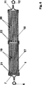
図1は、束として配置された中空繊維膜2を含んでいるケーシング1を有する本発明による膜モジュールを示す。中空繊維膜2はその一方の端部3を鋳造体4内に埋め込まれており、かつその第2の端部5は大体において自由に流体によって沿流可能である。
矢印6によって示された処理すべき流体は流入装置7を介して分配室8内に導かれ、この分配室に向かって中空繊維膜2の埋め込まれている端部3は開かれている。分配室8から処理すべき流体は一次流として中空繊維膜2の内腔9内に導入され、中空繊維膜をその埋め込まれていない端部5の方向に貫流する。内腔を貫流する際に生ずる圧力落差によって、中空繊維膜2に沿って一次流の一部が透過流として多孔質の半透過性の中空繊維膜2の壁を通って、中空繊維膜を取り囲む外室10内に流れ、その際壁を貫流する部分流は所定物質処理を受ける。所定物質処理された透過流は外室10内に集められ、外室を流出装置11の方向に貫流し、その際透過流は、中空繊維膜2の埋め込まれていない端部5の範囲において、内腔9から流出する一次流と1つになる。一次流と透過流とから1つにされた流体流は処理された流体12として膜モジュールから流出装置11を経て出る。流出装置は、図1に示した膜モジュールにおいては、中空繊維膜2の埋め込まれていない端部5の方のケーシング1の端部に配置されている。
流出装置を中空繊維膜2の埋め込まれていない端部5の方のケーシング1の端部に配置することは、複数の可能性のうちの単に1つであるに過ぎない。有利には−図2に示すように−図1におけるように一次流が内腔側に供給される場合には、流出装置11は鋳造体4に隣接せしめられていて、これにより中空繊維膜2の第1の埋め込まれている端部3の方向に配置されている。この場合一次流も、中空繊維膜2の内腔9の埋め込まれていない端部5から出た後に、中空繊維膜2を直接に取り囲んでいる外室10を貫流して、やはり外室10を貫流する透過流と混合されて、処理された流体12としてケーシング1から流出装置11を経て、出る。
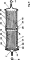
図3においては、1つの束に配置された中空繊維膜2が外側を一次流によって沿流される膜モジュールが示されている。この膜モジュールにおいては処理すべき流体6のための流入装置13は外室10内に開口していて、鋳造体4に隣接せしめられている。図示の例ではケーシング1は流入装置13のところに直径の拡大部14を有しており、これにより処理すべき流体を一次流として束の全横断面に一様に分配することができる。中空繊維膜2の第1の端部3はこの実施例では、内腔9が鋳造体4によってこの端部において閉じられているように、鋳造体4内に埋め込まれている。
処理すべき流体6は流入装置13を経て、中空繊維膜2を取り囲んでいる外室10内に流入し、一次流としてこの外室10を大体において中空繊維膜2に沿って流出装置11に向かう方向に貫流する。生ぜしめられる圧力落差に基づいて、透過流が、大体において中空繊維膜束の延び全体にわたって、中空繊維膜2の半透過性の多孔質の壁を通って中空繊維膜の内腔9内に入る。中空繊維膜2の壁を貫流する透過流において所定物質処理が行われる。処理された透過流は内腔9から、中空繊維膜2の第2の端部5における開口を経て、出て、そこの外室10内で一次流と1つになってから、一次流と透過流とから1つにされた流れが処理された流体12として流出装置11を経てケーシング1から導出される。
1つの束に配置された中空繊維膜が外側を一次流によって沿流される、図3に示した形式の膜モジュールにおいては、処理すべき流体が束横断面に一様に分配されるようにすることが重要である。このことは原理的には次のことによって達成することができる。すなわち、外室若しくは外室によって構成されている通路系の貫流の際に生ずる流動抵抗が、例えばこの外室内に流動抵抗を増大させるエレメントを入れることによって、充分に高くなるようにするのである。図4においては−流入装置13と流出装置11との間の流動方向で見て−小管形若しくは毛細管形のエレメント15が外室10内で中空繊維膜2の回りに入れられており、これらのエレメントは流入装置13に隣接せしめられた外室10の部分内の流動抵抗を増大させて、一次流の分配の一様化を生ぜしめる。
図4に示した膜モジュールにおいては更に、中空繊維膜2の埋め込まれていない端部5の範囲内で、別の流動抵抗を増大させるエレメント16が外室10内に入れられている。これらの、図示の例ではやはり小管形あるいは毛細管形に構成されているエレメント16によって、一次流のために外室の貫流の際に生じる流動抵抗が増大することができ、この形式で中空繊維膜の壁を通る透過流が増大することができる。
小管形若しくは毛細管形に構成されたエレメントの代わりに、類似の効果を得るために、例えば図4に示した範囲において、中空繊維膜に沿って別の流動抵抗を増大させるエレメントを、例えば相応して構成された流体を通すスペーサの形あるいは流体を通すフリースの形で、使用することができる。これらのスペーサあるいはフリースは、例えばコアの回りにらせん形に巻かれた中空繊維膜マットとして構成されている中空繊維膜束の場合に、巻きの際に生ずる層の間に帯状に置かれる。
流動抵抗を増大させるエレメント16の使用によって達成することができる効果と類似した効果は、中空繊維膜2が外側を一次流によって沿流される膜モジュールの場合に、ケーシング1の内部横断面を相応して構成することによっても得ることができる。中空繊維膜の範囲内でケーシング横断面を中空繊維膜2の埋め込まれていない端部5に向かう方向で先細にすることによって、束にまとめられた中空繊維膜の間の、埋め込まれていない端部5における間隔が、鋳造体の範囲における間隔よりも減少せしめられる。これによって流動抵抗が端部5に向かう方向で増大せしめられ、透過流の増大が生ずる。
図5は、分配室8に、かつ分配室を介して中空繊維膜2の内腔9に接続されている流入装置7並びに中空繊維膜2を取り囲んでいる外室10に開口していて、鋳造体4に隣接せしめられている流入装置13を有している本発明による膜モジュールを示す。本発明による膜モジュールのこのような実施例では、種々の流体を交互に一次流として、内腔側で中空繊維膜を通してかつ外側で外室を通して、導くことができる。
例えばまず特定の目標物質を含んでいる処理すべき流体を流入装置7を介して一次流として中空繊維膜2の内腔9内に導入することができ、その際流入装置13は閉鎖しておく。既に述べた形式で、中空繊維膜2の半透過性の多孔質の壁を通る透過流が生じ、透過流の所定物質処理が中空繊維膜2内で例えば目標物質の吸着によって行われ、これにより中空繊維膜2に目標物質が貯蔵される。目標物質を取り除かれた透過流は中空繊維膜2の内腔9から出た一次流と一緒に流出装置11を経てケーシング1から導出せしめられる。
中空繊維膜の容量が目標物質の吸着量で一杯になると、目標物質は簡単な形式で再び中空繊維膜から溶出させることができ、この場合溶出液体が流入装置13を経て外室10内に導入され、溶出液体は一次流として外室を貫流する。この過程中は流入装置7は閉じられたままである。やはり既に述べた形式で、次いで、透過流が中空繊維膜2の半透過性の多孔質の壁を、もちろん中空繊維膜の目標物質の貯蔵の場合とは逆方向で、貫通し、問題なく目標物質を中空繊維膜2から溶出することができる。
図6においては、段として互いに前後に配置されている2つの中空繊維膜束17,18を含み、その中空繊維膜19,20がそれぞれ一方の端部を鋳造体21,22内に埋め込まれている、本発明による膜モジュールが示されている。処理すべき流体6は流入装置7を経て膜モジュールのケーシング1内に導入され、まず一次流として内腔側で第1の中空繊維膜束17の中空繊維膜19を貫流する。この場合生ずる透過流は中空繊維膜19の壁内で所定物質処理を受ける。
外室を第1の中空繊維膜束17の範囲内で貫流する透過流は、中空繊維膜束17の中空繊維膜19の埋め込まれていない端部の範囲内で、中空繊維膜19の内腔から出た一次流と1つになり、このようにして生じた1回処理された流体の流れは、次いで再び内腔側で一次流として第2の中空繊維膜束18の中空繊維膜20内に入る。
ここで、第1の中空繊維膜束17の範囲内で行われた過程が繰り返され、第2の中空繊維膜束18の中空繊維膜20の壁内で、それを貫流する透過流において別の所定物質処理が行われる。これにより2回処理された流体流12は流出装置11を経て膜モジュールから導出される。前述のように、個々の段の中空繊維膜内に固定されている所定物質に作用する基は互いに異なっていることもでき、したがって、処理すべき流体は、複数の段を含んでいる膜モジュールを貫流する際に、複数の異なった所定物質処理を受けることができる。
中空繊維膜が外側を一次流によって沿流される場合に、中空繊維膜の複数の束を段として互いに前後に接続する可能性は図7に示されている。処理すべき流体は−一次流による内腔側の貫流の例におけるように−端面側で、換言すれば中空繊維膜の埋め込まれている端部から、流入装置7を経て、第1の段の前に配置されている分配室8内に導かれる。分配室8はその一方の側で鋳造体23に接しており、この鋳造体によって第1の段の束17の中空繊維膜19は、流入装置に面した端部を、その内腔がこの端部において閉じられているように、埋め込まれている。この鋳造体23内には、更に、流体を通すエレメント24が埋め込まれており、これらのエレメントは図示の場合には小管又は毛細管として構成されている。これらの流体を通すエレメント24を経て、処理すべき流体が一次流として第1の膜束17の中空繊維膜19の回りの外室25内に導かれる。前述のように、支配している圧力条件に基づいて、透過流が中空繊維膜19の半透過性の多孔質の壁を通して流れ、そこで第1の所定物質処理を受ける。中空繊維膜19の埋め込まれていない端部の範囲において、外室25内で一次流が透過流と1つになる。
このようにして生じた、第1の所定物質処理を受けた流体流は、第2の段において中空繊維膜20の束18に供給される。この段は第1の段と同様に構成されている。ここでも鋳造体26は流体を通すエレメント24を有しており、これらのエレメントによって、別の所定物質処理を受けるべき流体が第2の束18の中空繊維膜20の回りの外室27内に導かれる。ここで行われる過程は第1の段における過程に相応しており、その際第2の段の透過流は別の所定物質処理を受ける。次いで2回処理された流体流12は流出装置11を経て膜モジュールから導出される。
段として互いに前後に配置された2つの中空繊維膜束17,18を有し、中空繊維膜19,20の外側を一次流によって沿流される、図7に図示した膜モジュールの変化形は図8に示されている。図8による膜モジュールにおいては、処理すべき流体6の導入はやはり流入装置7を経て行われる。一次流は次いで端面側から、換言すれば鋳造体23,26と、埋め込まれた、鋳造体23,26によって閉じられている中空繊維膜19,20の端部とによって形成される平面から、その都度の中空繊維膜の回りの外室25,27内に導かれる。
その都度の束17,18の中空繊維膜19,20の埋め込まれている端部を回って、リング形の流体を通すエレメント28,29が鋳造体23,26内に埋め込まれており、これらのエレメントは図示の例では、短い小管あるいは毛細管として構成されていて、鋳造体23,26を貫通している。鋳造体23,26の範囲内でケーシング1はその内径の拡大部30,31を有している。これによって一面では処理すべき流体の、流体を通すエレメント28,29への一様な供給が達成される。他面ではこれらの拡大部30,31によってリング通路32,33が流動方向で鋳造体23,26の後方に構成され、これらのリング通路内に、流体を通すエレメント28,29が開口し、これらのリング通路によって一次流をその都度の束横断面に一様に分配することができる。The present invention is a membrane module for the treatment of a predetermined substance of a fluid,
a) comprising a casing having a longitudinal extension;
b) a hollow fiber membrane which is arranged in the casing in the direction of the extension in the direction of the casing and has a semipermeable wall having a porous structure, The hollow fiber membrane has a first end and a second end and at least one lumen extending along its longitudinal axis, wherein each hollow fiber membrane is simply its first. Embedded in the casing by the casting body only at one end, and can generally flow freely at its second end, and the hollow fiber membrane is then formed by the inner wall of the casing and by the casting body. Each having an inner side facing the at least one lumen and an outer side facing the outer chamber,
c) comprises at least one inflow device for introducing the fluid to be treated into the casing, only on one side (inside or outside) of both sides of the hollow fiber membrane,
d) comprising an outflow device for withdrawing the treated fluid from the casing, wherein the outflow device is open towards the outer chamber around the hollow fiber membrane,
Concerning the format.
The treatment of certain substances in fluids has gained increasing importance in applications such as biotechnology, medicine or chemical technology. Fluids in this case are intended to include gases, gas mixtures and generally liquids such as protein solutions, prefiltered suspensions or clear solutions. An example of treatment of a given substance is to extract the agent from a cell suspension in which the genetically modified cells produce substances such as antibodies, hormones, growth factors or enzymes, usually in small concentrations. . One important application is also the removal of unwanted substances from human plasma in vitro and the collection of components such as immunoglobulins or blood clotting factors from donated plasma. Finally, a widespread application is the treatment of liquids with catalysts or biocatalysts, such as hydrolysis of oils with lipases immobilized on a substrate.
The treatment of a predetermined substance of the fluid is often performed as follows. That is, the fluid to be treated is brought into contact with the support material, and in a special and selective manner, the target substance contained in the fluid, that is, on the group or substance that interacts with the substance to be treated with the predetermined substance. And / or fix within. Such interactions include, for example, cation or anion exchange, hydrophilic and hydrophobic interactions, hydrogen bonding, affinity or enzymatic or catalytic reactions. In substance separation by affinity such as affinity chromatography, for example, a ligand is linked to a support material or fixed in the support material, and this ligand can be specifically identified by adsorbing individual target substances or all classes of substances. It has the function to combine with. This target substance is called ligato. An example of a given class of ligands is a positively charged diethylaminoethyl (DEAE) group or a negatively charged sulfonic acid (SO 3 ) Groups that adsorb positively or negatively charged molecular groups. A specific ligand is, for example, an antibody against a specific protein that is bound to the antibody as a ligate.
Important criteria in the treatment of a given substance in a fluid are productivity and selectivity. The important thing about productivity is that it has groups per unit volume that act on as many predetermined substances as possible that can interact with the target substances contained in the fluid to be treated. is there. At the same time, efforts must be made to maximize the transport of the target substance to the group or substance acting on the given substance.
A support material for ligands often used in affinity chromatography is Sepharose particles that exist in the form of bulk deposits within the chromatography column. In this case, a high concentration of ligand can be achieved with high selectivity, but the productivity is negligible as is well known due to the high pressure drop of the particle column and the compressibility of the Sepharose particles. In addition, the access of ligato to the ligands contained within the cephalose particles is diffusion controlled, which can result in long residence times due to the low diffusion rate, especially when separating large particles such as proteins. Only a small amount of flow and a little productivity are provided.
An improved chromatographic column material consisting of rigid, porous particles that can flow through by convection is described in US-A-5 019 270. Unlike the pillar material described above, this particle allows for a reduction in residence time and an increase in productivity. Nevertheless, the chromatography column filled with this particle also has a non-uniform flow, which is negative with respect to the uniform utilization of all the ligands present in the chromatography column. Works. Furthermore, the technical control of the required pressure becomes more expensive as the diameter increases.
The aforementioned shortcomings of particulate support materials have developed a series of methods for treating a given substance in a fluid using a porous semipermeable membrane. Due to its porous structure, the membrane has a large inner surface, and therefore the membrane can be linked to a large number of functional groups at a high concentration per unit volume, and these groups are processed through the membrane. Interact with the fluid to be [e.g. Klein, “Affinity Membranes” (Affinity Membranes), John Wiley & Sons, Inc. Issue, 1991; Brandt et al., “Membrane-Based Affinity Technologie for Commercial Scale Purifications”, see Bio / Technology Vol. 6 (1998) pages 779-782].
There are membranes made of very different materials and having various porous structures, conforming to the physicochemical properties of the fluid to be treated and, for example, the fluid to be treated having the target substance contained therein It can be conveyed by convection through. In addition, the membranes are generally superior because of their very small wall thickness (eg <100 μm), for example a short transport distance of the fluid to be processed to the interacting groups fixed in the membrane. The time is relatively short, the pressure loss is small, the flow velocity is linear, and thus the coupling rate is high.
A series of modules are described that include such membranes and that are used in a method of treating a given substance in a fluid. In this case, a so-called dead end system or dead end module can be distinguished from a cross flow system or cross flow module.
In the case of the cross flow method, the feed flow flows parallel to one side of the membrane. In this case, a portion of the feed stream penetrates the membrane. The partial flow that penetrates is derived as a permeate flow, and the partial flow remaining on the supply flow side is derived as a stagnant flow. In this case, an additional fluid flow can also be introduced on the permeate side of the membrane, which fluid flow accepts a partial flow through the membrane.
In contrast to this, in the dead end system, the entire fluid flowing into the membrane module as a supply flow is guided through the membrane, and is led out as a filtered flow or a permeate flow on the exhaust side opposite to the inflow side of the membrane.
Dead-end membrane modules based on hollow fiber membranes are often used in the area of ultrafiltration or microfiltration and are often used, for example, for liquid gasification. In some of these membrane modules, for example as described in EP-A-0 138 060 or EP-A-0 659 468, the hollow fiber membrane is bent into a U shape, the end of which is It is embedded in the casting body and opened. The gas or liquid to be filtered flows, for example, into the lumen of the hollow fiber membrane through the open end and permeates into the outer chamber of the hollow fiber membrane based on the pressure difference. When used for filtration, the filtered components remain in the membrane.
In another construction of the dead-end membrane module, the hollow fiber membranes are arranged roughly in a casing in a straight line, one of their open ends being embedded together in the casting body, In contrast, their second ends are free, in other words not embedded. The unfilled end of the hollow fiber membrane is closed in these modules. Such membrane modules are described, for example, in US-A-4 002 567, US-A-4 547 289, EP-A-0 138 060 or EP-A-0 732 142.
A disadvantage in all dead-end membrane modules is that they are often not suitable for suspension treatment, for example when the particles contained in the suspension are of small pore diameter. These particles constitute a layer on the membrane wall and block the membrane. Such dead-end modules can only be operated in combination with a pre-connected pre-purification stage, for example for use in affinity separation methods for suspensions. This makes such a method, however, less effective, for example, in many cases by losing most of the target substance by such pre-purification.
These disadvantages relating to the availability of modules operating in a dead-end manner, for example in suspension, can be avoided at least in part when using cross-flow modules. In the cross-flow module, the composition of the layer of suspended particles can be reduced with a sufficiently large shear stress due to a feed stream flowing parallel to the membrane surface.
WO 90/05018 discloses a cross flow module having a hollow fiber membrane for use in affinity separation methods. In this case, the liquid containing ligato is introduced into the module casing via an inflow device and flows tangentially along the hollow fiber membrane side into which the ligand is connected. Part of the liquid permeates through the membrane, where ligato is added to the ligand and reacts as a permeate on the opposite side of the membrane from the inflow side. The stagnant flow and the permeate flow are derived via separate outflow devices.
A variation of the cross flow process is described in WO 93/02777. For special removal of components from the blood, a plasma filter consisting of hollow fiber membranes bent into a U shape and whose ends are embedded in a specially formed casing is useful. These hollow fiber membranes flow through the lumen side with blood, and the treatment of the predetermined substance is performed in the outer chamber with the purifying agent around the hollow fiber membrane in the casing in the plasma separated by the membrane. The membrane bundle is divided into an inflow branch and an outflow branch. The positive transmembrane pressure that occurs in the region of the inflow branch causes convective transport of plasma through the membrane into the outer chamber. In the region of the outflow branch, the treated plasma flows back into the lumen of the hollow fiber membrane due to the negative transmembrane pressure that occurs there, and is recombined with the blood.
EP-A-0 341 413 describes an adsorption module for the treatment of complete blood, which is contained within the module, both ends embedded in the casting and the ligand. The hollow fiber membrane provided with is pierced by blood on the lumen side in a cross-flow manner. In this case, the plasma passes through the hollow fiber membrane wall as a permeate flow and enters the outer chamber surrounding the hollow fiber membrane, whereupon the plasma is processed in the membrane wall. In a special embodiment, this module does not have an outlet for the permeate flow, and the plasma separated as permeate flow collects in the outer chamber around the capillary tube and again depends on the pressure conditions that are produced, resulting in a hollow fiber membrane wall. Through the lumen of the hollow fiber membrane. In such a module concept, the permeate must pass through the membrane wall twice, so that the permeate and thus the portion of the plasma that is treated with a given substance is relatively small. As a result, the required processing time is considerably long.
The aforementioned modules operating in a crossflow manner have various drawbacks. For example, if the permeate flow and the stagnant flow are separated, an additional pump and / or control mechanism is required. In addition, these modules are expensive to manufacture due to the embedded ends on both sides of the hollow fiber membranes, and this embedding can function with respect to the treatment of certain substances when the module length is less. The proportion of the film portion without the increase increases. In cross-flow modules, it is often necessary to connect multiple modules back and forth with each other because only a partial flow of the fluid to be treated as a whole is directed through the membrane. In that case, however, the cost of manufacturing and operating the prior art cross-flow module is significantly increased.
The object of the present invention is therefore to provide a membrane module for the treatment of a predetermined substance of a fluid of the type mentioned at the outset so that the disadvantages of the prior art described above are at least reduced and easy to manufacture. It is to be able to adapt flexibly to the treatment, in particular to suspensions.
It is a further object of the present invention to at least reduce the aforementioned drawbacks in a method for the effective treatment of certain substances in a fluid using a semi-permeable membrane with a porous structure.
This problem is solved in the membrane module according to the superordinate concept of
Furthermore, this subject is a method for treating a fluid with a predetermined substance using this membrane module, in which the hollow fiber membrane is oriented in each case towards the at least one lumen and the outer chamber. At least in the following stages:
a) introducing the fluid to be treated into the casing;
b) guiding the fluid to be treated as a primary flow along one of the sides of the hollow fiber membrane, and a part of this primary flow flows as a permeate flow through this one side into the wall of the hollow fiber membrane, In each case through the other side, in which the fluid to be treated is treated with a certain substance of the fluid in the part forming the permeate flow and then flows out of the wall through the other side. To do,
c) combining the permeate stream that is allowed to flow through the wall of the hollow fiber membrane with the primary stream flowing on one side of the hollow fiber membrane after treatment of the predetermined substance;
d) deriving a flow of treated fluid, drawn from the primary flow and the permeate flow, from the casing;
It is solved by making it contain.
In this case, the hollow fiber membrane in the meaning of the present invention includes a membrane shape such as a membrane hose or a membrane tube. The fluid to be treated is generally a fluid containing a specific substance or target substance to be treated with a predetermined substance.
In the membrane module according to the invention, or when carrying out the method according to the invention for fluid treatment of a given substance, the flow along the hollow fiber membrane is carried out in a cross-flow manner: the fluid to be treated as a primary flow Along the one of both sides of the hollow fiber membrane, in other words, along the side facing the at least one lumen of the hollow fiber membrane or the side facing the outer chamber of the hollow fiber membrane, Flowing parallel to the longitudinal extension, a portion of the fluid to be treated flows as a permeate flow through the wall of the hollow fiber membrane each time to the other hollow fiber membrane side. In this case, the lumen of the hollow fiber membrane means a hollow fiber membrane inner chamber surrounded by the wall of the hollow fiber membrane and extending in the direction of the longitudinal axis of the hollow fiber membrane, and at least one of the hollow fiber membranes. The side facing one lumen is the inner surface of the hollow fiber membrane, and the side facing the outer chamber is the outer surface of the hollow fiber membrane. In this case, the hollow fiber membrane can have more than one hollow chamber extending along the axis of the hollow fiber membrane, in other words more than one lumen. Such hollow fiber membranes are described, for example, in DE-OS 30 22 313 or DE-OS 28 42 835.
The bundle contained in the casing has a plurality of side-by-side hollow fiber membranes so that a correspondingly large amount of fluid can be treated with a given substance. However, in special cases, the bundle can consist of one individual hollow fiber membrane. Of course, the bundle can also be assembled from a plurality of partial bundles.
In an advantageous embodiment of the membrane module according to the invention, at least one inflow device opens into the outer chamber and is adjacent to the casting. In this case, the lumen of the hollow fiber membrane is preferably closed at the end where the hollow fiber membrane is embedded.
In a further advantageous embodiment of the membrane module according to the invention, at least one inflow device is connected to the distribution chamber, which is adjacent to the cast body on the end face side and is spaced by the cast body. It is separated from the outside room. In this case, in one advantageous embodiment, the distribution chamber is connected to the outer chamber via a passage part mounted in the casting body, and the lumen of the hollow fiber membrane is a first end in which the hollow fiber membrane is embedded. Is closed. In the simplest case, these through-holes are holes that penetrate the casting. However, the passage is preferably designed as a fluid-permeable element, which is embedded in the casting body together with the hollow fiber membrane, in which case such an element is a capillary or a small tube, in particular A favorable experience was made.
In the aforementioned embodiment of the membrane module according to the invention, the fluid to be treated is introduced into the outer chamber around the hollow fiber membrane. In this case, the outflow device is preferably in the region of the second end of the hollow fiber membrane, in other words at the end of the casing opposite the casting. As a result, the fluid to be treated flows as a primary flow through the outer chamber around the hollow fiber membrane in the direction of the outflow device, generally along the longitudinal extension of the hollow fiber membrane. In these cases, a passage system for the primary flow is constituted by the outer chamber around the hollow fiber membrane.
Due to the pressure drop that occurs during the flow through this passage system, a portion of the primary flow flows through the semipermeable porous wall of the hollow fiber membrane as a permeate flow, generally over the entire extension of the hollow fiber membrane. In this case, the predetermined substance is processed in this partial flow. The treated partial stream then enters the lumen of the hollow fiber membrane, where the lumen serves as a collection chamber for the permeate flow. Through the lumen or collection chamber, the permeate flows through the opening at the second end of the hollow fiber membrane, exits and is combined with the primary flow that flows through the passage system, and then the primary and permeate flows are combined. The resulting flow is led out of the casing through the outflow device as processed fluid.
In a further advantageous embodiment of the membrane module according to the invention, at least one inflow device is also connected to the distribution chamber, which is adjacent to the cast body on the end face side and is spaced by the cast body. It is separated from the outside room. However, in this embodiment, the hollow fiber membrane penetrates the casting with its first end, in other words its embedded end, and is open at this end. In this case, the fluid to be treated flows as a primary flow into the distribution chamber through the casing inflow device and from there into the lumen of the hollow fiber membrane, and flows through the lumen along its longitudinal extension. The cavity exits through an opening at the second, non-embedded end of the hollow fiber membrane. In short, the primary flow passes through the hollow fiber membrane on the lumen side, and the entire lumen of the hollow fiber membrane forms a passage system for the primary flow.
Due to the pressure drop that occurs during lumen flow, a portion of the primary flow flows through the semi-permeable porous wall as a permeate flow, generally over the entire length of the hollow fiber membrane. In this case, the predetermined substance is processed in this partial flow. The partial stream that has been treated with a given substance then exits into the outer chamber surrounding the hollow fiber membrane, which in this embodiment serves as a collection chamber for the permeate flow. The permeate flows through this outer chamber in the direction of the casing outflow device, in which case it is combined with the primary flow flowing out of the passage system, in other words, the inner cavity, in the outer chamber inside the casing. The treated fluid, in other words the combined fluid flow of the primary flow and the permeate flow, is led out of the casing via the outflow device. In this case, in the previous embodiment, the outflow device can be present at various locations along the casing, but is preferably close to the casting.
In another advantageous embodiment, the membrane module according to the invention comprises at least one inflow device that opens into the outer chamber and is adjacent to the casting and at least one inflow connected to the distribution chamber. The distribution chamber is adjacent to the casting body on the end face side and is spatially separated from the outer chamber by the casting body, wherein the distribution chamber is connected to the lumen of the hollow fiber membrane. The hollow fiber membrane penetrates the casting with its first end and is open at this end. In particular, it is possible in particular to alternately flow one fluid as a primary flow through the hollow fiber membrane on the lumen side and one fluid as a primary flow to flow through the outer chamber on the outside.
For example, in the case of treatment of a predetermined substance of a fluid, in order to remove a specific target substance contained in the fluid, for example, by adsorbing it to an appropriate group in the membrane, first, the fluid to be treated is firstly treated. As described above, the hollow fiber membrane can be allowed to flow on the lumen side, and as described above, the wall of the hollow fiber membrane can be allowed to flow from the inside toward the outside using the partial flow as the permeate flow. After finishing the treatment of the predetermined substance, in order to elute the target substance adsorbed on the membrane, the elution fluid is made to flow along the outside of the hollow fiber membrane as a primary flow, and the partial flow is made hollow as a permeate flow. It can flow from the outside to the inside through the wall of the fiber membrane to receive the target substance. Of course, it is also possible to reverse the operation mode, in other words, to introduce the fluid to be treated into the outer chamber and then introduce the elution fluid into the lumen of the hollow fiber membrane.
Such an embodiment in which one fluid can alternately flow as a primary flow to one side of the hollow fiber membrane and then another fluid as the primary flow to the other side of the hollow fiber membrane is advantageously If the particles contained in the suspension can be deposited in the porous structure of the hollow fiber membrane, the suspension can be used for the treatment of a predetermined substance. In the first process step, a primary flow is first introduced into the membrane module according to the invention on one side of the hollow fiber membrane, whereby particles of the corresponding size are introduced into the porous structure or through the permeate flow. On top, it can be captured. Then, in the next stage, a primary flow or a second fluid is introduced as a primary flow on the other side of the hollow fiber membrane, and a permeate flow is formed by the pressure conditions present, this permeate flow being the permeate in the first stage. It flows through the walls of the hollow fiber membrane in the opposite direction to the flow, in which case the membrane structure is washed away of the particles that were trapped in the previous step. In this case, the second fluid can at the same time be the elution liquid for another target substance that was also retained in the membrane structure in the first method step.
When sizing the collection chamber for the permeate flow, it is important that the flow resistance that occurs when the permeate flows through the collection chamber is less than the flow resistance that occurs when it flows through the semi-permeable wall It is. At the same time, for a hollow fiber membrane, the largest possible part of the total volume defined by its outer contour consists of a semi-permeable porous membrane wall in which the treatment of a given substance can take place. Should be.
Along with other influencing factors such as the hydraulic permeability of the membrane or the flow resistance in the collection chamber, the permeate flowing through the semipermeable wall of the hollow fiber membrane is generated by the primary flow along the hollow fiber membrane. Determined by the pressure gradient dp / dx. In this case, dp is the differential pressure change along the differential distance dx in the direction of the primary flow. As the value of this pressure gradient increases, the portion of the permeate flow through the membrane wall, and thus the primary flow, that is subject to treatment with a given substance increases. The pressure drop in the direction of the longitudinal extension of the hollow fiber membrane, in other words, the pressure drop along the passage system that flows through by the primary flow, in other words, the primary flow increases as the flow rate of the passage system increases. As it increases.
Furthermore, the value of the pressure drop dp / dx increases as the flow cross-section of the passages forming the passage system through which the primary flow passes, in other words—depending on the embodiment— It increases as the cross section of the intermediate chamber between the hollow fiber membranes and between the hollow fiber membranes and the inner wall of the casing becomes small. When the flow cross-sectional dimension of the passage of the passage system is sufficiently small, a sufficiently high pressure gradient is produced by the flow rate in the passage system or the passage system in combination with an appropriate flow rate, and the porous membrane structure Significantly larger convective transport due to the permeate flow is superimposed on the diffusive transport. In other aspects, the cross-section of the passage is made too small so that the fluid to be treated can still flow through the passage without hindrance, for example in the case of a certain substance treatment of a suspension. Must not.
In the membrane module according to the invention, it is advantageous to use hollow fiber membranes whose walls have a generally uniform thickness. In this manner, roughly the same flow-through distance is also produced at each point of the hollow fiber membrane, which is particularly advantageous for making the residence time of the fluid to be treated as uniform as possible.
When a plurality of hollow fiber membranes are used as a bundle, the hollow fiber membranes grouped in the bundle are spaced from each other by a spacer, and thus a defined intermediate between the hollow fiber membranes around the hollow fiber membranes. It is advantageous if an outer chamber with a chamber is constructed. In this manner, uniform flow of the individual hollow fiber membranes in the bundle is allowed. Furthermore, when the primary flow flows along the outside of the hollow fiber membrane, the size of the flow cross section of the passage of the passage system surrounding the hollow fiber membrane can be adjusted via the spacer, thereby The resulting pressure gradient can be influenced. In the case of the predetermined substance treatment of the suspension and when the primary flow is introduced into the outer chamber, it is possible to adapt the size of the particles contained in the suspension via the spacer.
Advantageously, the spacer is configured such that it has an elastic component. This allows such bundles of hollow fiber membranes to be placed in a simple manner into the casing of the membrane module, in which case the bundles are initially slightly compressed, with some spacing between the hollow fiber membranes. It is reduced and pushed into the casing and then relaxed, thereby increasing the spacing between the hollow fiber membranes again. As a result, the bundle of hollow fiber membranes comes into contact with the inner wall of the casing at the outer periphery thereof, and unwanted edge flow along the inner wall of the casing is avoided.
The hollow fiber membranes inside the bundle are preferably spaced by spun yarn. In this case, in principle, it is sufficient to insert the spun yarn between the hollow fiber membranes. However, the hollow fiber membrane is preferably incorporated into the at least one hollow fiber mat by means of a spacer, which spacer is particularly preferably a spun yarn. Such hollow fiber mats can advantageously be produced in a known manner as knitted mats, as woven mats or as woven bands, but also as knitted mats or as knitted needle mats. In the case of weaving or knitting, the spun yarn is a woven yarn or warp yarn extending in the transverse direction with respect to the hollow fiber membrane. By means of these transverse threads, the hollow fiber membranes are preferably kept at a uniform distance from one another and are arranged substantially parallel to one another inside the mat. With such a mat, it is possible to manufacture a bundle of hollow fiber membranes having an accurate arrangement and capable of forming a uniform passage system between the hollow fiber membranes.
In another embodiment of the membrane module according to the invention, the hollow fiber membrane is incorporated into the respective hollow fiber mat by means of a planar, preferably strip-shaped coupling element, in which case these strip-shaped coupling elements are At the same time, it functions as a spacer. Such a strip-like coupling element can preferably extend transversely to the hollow fiber membranes arranged substantially parallel to each other, but also at another angle, for example applied in a point-like manner. It is laminated on the hollow fiber membrane with an adhesive, for example an adhesive based on polyurethane.
Such mats of hollow fiber membranes are preferably superimposed on piles or bundles of mat layers that are individually defined in width. However, the hollow fiber membrane mats can advantageously be folded into piles or bundles in a zigzag form in a single layer or stacked on top and bottom. In another advantageous embodiment of the present invention, the hollow fiber membrane mats mentioned above are stacked one on top of the other in a single layer or multiple layers, the hollow fiber membranes of the individual layers being substantially parallel to one another, The bundle is wound in a spiral manner about the axis or core of the bundle, substantially parallel to the longitudinal extension of the bundle.
In bundles or piles produced in this way, the individual winding layers or individual layers are advantageously individually, for example by means of woven or knitted yarns or inserted coupling elements, and optionally additionally individually. Are spaced apart from each other by, for example, a fluid permeable fleece or fabric inserted between the wound layers.
In another advantageous embodiment, the bundle consists of at least two vertically stacked hollow fiber mats, the hollow fiber membranes inside each mat being spaced apart from each other, the mat being centered on an axis or core In this case, the hollow fiber mats are stacked one above the other so that the hollow fibers of the hollow fiber mats that overlap one above the other are arranged so as to cross each other. The production of such a bundle is described in detail in EP-A-0 285 812. In such a bundle, it has been found that the angle between the hollow fiber membranes arranged in crossing is between 0 ° and 120 °, preferably between 30 ° and 90 °. .
In another advantageous embodiment, the hollow fiber membrane bundles contained in the membrane module according to the invention consist of core bundles, these core bundles having hollow fiber membranes arranged around the support yarn, The hollow fiber membrane arranged around the support yarn is wound with at least one wound yarn. The hollow fiber membranes contained in the core bundle are spaced from each other by the support yarn. At the same time, the wound yarns separate the core bundles that bundle the hollow fiber membrane bundles from each other, thus ensuring good flowability of the hollow fiber membranes contained within the hollow fiber membrane bundle as a whole. Such hollow fiber membrane bundles assembled from core bundles are described in EP-A-0 732 141.
In order to increase the efficiency of the treatment of a given substance, it is advantageous to carry out steps b) and c) of the method according to the invention several times. This can be achieved as follows. That is, a plurality of bundles of hollow fiber membranes are arranged in front and back as a step in the longitudinal direction of the hollow fiber membranes in the casing. Connecting the stages in this way back and forth is an example of a membrane module in which the primary flow is guided through the lumen of the hollow fiber membrane if the casing and the transition between the individual stages are correspondingly configured However, it is also possible in embodiments where the primary flow flows through the outer chamber around the hollow fiber membrane.
By connecting a number of stages back and forth with each other, simultaneously each individual stage in its longitudinal dimension, in other words the dimension in the direction of the longitudinal extension of the hollow fiber membrane contained in each stage. , And thus avoiding concentration changes with respect to possible critical components in the fluid to be treated. This is particularly true, for example in the case of certain substance treatments of blood, where at least a part of the suspended particles are retained by the semipermeable membrane wall of the hollow fiber membrane and at the same time an excessive amount of suspended particles. It makes sense in certain substance treatment methods of suspensions that avoid high concentrations. Due to the relatively short hollow fiber membrane, only a small partial flow is taken from the primary flow along the hollow fiber membrane, so that the concentration change remains slight until the next match of the primary and permeate flows.
Advantageously, in the membrane module according to the invention, the number of steps in the casing is between 1 and 100. The best number of stages has been demonstrated to be between 1 and 10. In this case, the individual stages are spaced apart from each other, and neither the primary flow nor the permeate flow is obstructed by the stage located locally in the flow-through direction of the casing and the primary and permeate flows are good. It is advantageous to allow smooth mixing. Uniform mixing is advantageous, for example, to avoid unwanted concentration fluctuations.
Of course, it is also possible to connect a plurality of membrane modules according to the invention, which comprise a plurality of stages of hollow fiber membranes, one after the other, adapted to the needs of the processing method. In another advantageous embodiment of the method according to the invention, the fluid to be treated is recirculated and the treatment is carried out several times until the desired treatment rate is achieved.
Hollow fiber membranes having various outer contours, in other words various outer contours when viewed in cross-section, can be used. Hollow fiber membranes can have, for example, roughly round or round, triangular, square, hexagonal or octagonal contours, and are oval, elliptical, 3 layers, 4 layers, etc. Can be configured. For use in a membrane module according to the invention or for carrying out the method according to the invention, a hollow fiber membrane having a wall thickness between 15 μm and 1500 μm, best a wall thickness between 100 μm and 300 μm Hollow fiber membranes having The hydraulic diameter of the hollow fiber membrane used is preferably from 50 μm to 900 μm, in this case the hydraulic diameter d h D h = 4 * A / U, where A is the area of the flow cross section of at least one lumen of the hollow fiber membrane, and U is the circumference of the flow cross section of the hollow fiber membrane lumen in each case To express. When the hollow fiber membranes each have a plurality of lumens, A and U respectively represent the area or circumference total value of the individual lumens of the respective hollow fiber membranes. Particularly advantageous are hollow fiber membranes having a hydraulic diameter of between 200 and 400 μm.
In the embodiment of the membrane module according to the invention in which the flow along the outside of the hollow fiber membrane is carried out by the primary flow, the aforementioned range for the hydraulic diameter is likewise constituted by the outer chamber around the hollow fiber membrane. This is the case for the cross-section of the passages in the passage system. In this case, the hydraulic diameter d of the passage h1 D h1 = 4 * A 1 / U 1 Is defined as A 1 Is the area of the flow cross section perpendicular to the hollow fiber membrane between the hollow fiber membranes, U 1 Is the total value of the outer periphery of all hollow fiber membranes and the inner periphery of the casing. In this case, the hydraulic diameter d of the hollow fiber membrane h Is preferably the hydraulic diameter d of the passage h1 Smaller by a factor of 1.2-12.
In an advantageous embodiment of the invention, the permeate stream flows through the semi-permeable wall of the hollow fiber membrane and convectively conveys the target substance through the membrane. This presupposes that the semi-permeable porous wall of the hollow fiber membrane has a pore size that allows transport of the target substance through the membrane wall. Of course, when the average pore size of the membrane is maximized for a given pressure gradient in the passage system flowed by the primary flow and a given geometric dimension of the hollow fiber membrane, the permeate flow is Maximized. However, in application, the pore size must also match the size of the target material, which is in the form of dissolved macromolecules, but also in the form of small particles with a particle size in the lower micrometer range. May exist. At the same time, it may often be necessary, for example in the case of a certain substance treatment of the suspension, that the membrane performs a separation function and retains the non-target substance components contained in the suspension. This means that the size of the stoma must not exceed a certain maximum value. This prevents blockage of small pore systems or unwanted interactions between, for example, such retained components and the groups in the membrane that act on a given substance for interaction with the target substance. Can do.
In another aspect, with respect to the use of the membrane module according to the invention or the embodiment of the method according to the invention described below, the pore size is as small as possible and the pore volume is as large as possible or porous. It is rather important to use as large a membrane as possible and to make the surface inside the membrane, in other words, the pores formed as small as possible, for the treatment of certain substances. . Advantageously, the hollow fiber membranes used according to the invention have an average porosity of between 50 and 90% by volume. The average porosity means the ratio of the small pore volume of the hollow fiber membrane to the wall volume of the hollow fiber membrane, and the wall volume is a combination of the small pore volume and the material constituting the membrane structure.
The requirements for the structure of the hollow fiber membrane, in other words the distribution of pore sizes over its structure and wall thickness, derive from the respective application of a given substance treatment. The membrane structure can be isotropic over the wall thickness, in other words, the pore diameter is largely constant within the membrane wall, and the membrane structure can be anisotropic, symmetric or even asymmetric. And the membrane can have on its one side a remarkably tight pore structure layer, in other words a skin layer. In the case of an asymmetric membrane, the tight layer can face the primary flow, or but the collection chamber for the permeate flow. For example, in the case of a certain substance treatment of the suspension, it may be necessary for the membrane to have a small pore diameter on the side facing the primary flow in order to achieve a specific separation action. In order to achieve as large a permeation flow as possible through the membrane wall at the same time, however, the remaining membrane structure is advantageously coarsely porous, but not excessively porous depending on the application, thereby being To achieve a large internal surface.
Preference is given to using hollow fiber membranes with an average pore diameter of between 0.005 and 5 μm, particularly preferably hollow fiber membranes with an average pore diameter of between 0.1 and 3 μm.
Different methods are applied to determine the average pore diameter depending on the size of the pore diameter and depending on the membrane structure. For a generally isotropic pore structure, the pore diameter is determined indirectly by filtration experiments, in which an aqueous dextran solution having a predetermined size distribution of dextran molecules is filtered through the membrane. From the relative amount of crest measured in this case as a function of the nominal molecular diameter, the pore diameter distribution and the average pore diameter are calculated therefrom. This method is described in, for example, K.K. Sakai, J. et al. By Membrane Science 96 (1994), 91-130, or by Shin-ichi Nakao, J. et al. Membrane Science 96 (1994), 131-165, for dialysis membranes or filtration membranes.
For example, for an anisotropic membrane having a layer with a tight pore structure, a determination based on filtration experiments, also cited to determine the average pore diameter inside the tight layer The law is cited. In order to determine the average pore diameter in the range of the coarse pores of the anisotropic membrane, Zeman et al. The image analysis method according to Membrane Science 71 (1992), 221-231 is used. This method is suitable for pore size ranges between 0.1 μm and 5 μm, and of course for isotropic and anisotropic pore structures.
In order to use the membrane module according to the invention or the method according to the invention especially for clear solutions or suspensions, the hollow fiber membrane has an average pore diameter which is largely constant over its wall over at least 80% of the wall thickness. It is advantageous to have This makes it possible to achieve a large internal surface in combination with groups in the membrane acting on a large number of fixed predetermined substances and at the same time with a small pressure drop when flowing through the membrane wall and thus with a large permeate flow. . A generally constant mean pore diameter means one that does not change more than ± 50% over the wall thickness.
In order to treat a suspension with a given substance, on the side facing the primary flow, the mean pores smaller than the membrane area with a generally constant mean pore diameter connected in the direction of the lumen. It has been found advantageous to use a membrane having a layer having a diameter. This layer is preferably between 1 and 5 μm thick and has an average pore diameter which is smaller by a factor of 5 to 50 than the average pore diameter within the connected area.
In the membrane module according to the invention or for carrying out the process according to the invention, a porous hollow fiber membrane with a large internal surface is preferably used. Wall volume 1cm 3 2m per 2 And 300m 2 A hollow fiber membrane with a BET surface between and has been demonstrated, best with a wall volume of 1 cm 3 8m per 2 And 30m 2 A hollow fiber membrane with a BET surface between is demonstrated. The BET method based on nitrogen adsorption measurements to determine the surface of a porous membrane structure is Kaneko, J .; Membrane Science 96 (1994), 59-89.
No limitation is imposed on the material constituting the hollow fiber membrane according to the present invention. For example, glass, ceramic, SiO 2 , Membranes made of inorganic materials such as carbon or metal, organic polymers or mixtures thereof can be used. The polymer can have hydrophilic and / or hydrophobic properties, and the polymer can be a cellulose polymer such as cellulose or regenerated cellulose, modified cellulose such as cellulose ester, cellulose ether, amine modified cellulose and cellulose. From the group of polymer mixtures, synthetic polymers such as polyacrylonitrile and corresponding copolymers, polyurethane-containing polymers, polyaryl sulfones and polyallyl ether sulfones such as polysulfone or polyether sulfone, polyfluorine, Vinylidene chloride, polytetrafluoroethylene, water-insoluble polyvinyl alcohol, aliphatic and aromatic polyamides, polyimides, polyetherimides, polyesters, polycarbonates, polyolefins such as polyethylene, Pyrene, polyvinyl chloride, polyethylene oxide phenyl, polybenzimidazole and poly benzimidazolone and therefrom resulting transformation mixture can pick blend, from the group of mixtures or copolymers of these polymers. These polymers or copolymers may be mixed with another polymer such as polyoxyether, polyhydroxyether, polyethylene glycol, polyvinylpyrrolidone, polyvinyl alcohol or polycaprolactone, or an inorganic substance such as SiO2 as an additional substance. Can do. In each case, the membrane can be surface transformed, for example, to produce specific properties of the membrane surface, for example in the form of specific functional groups. If a polyolefin polymer is used, it may be necessary to coat at least the inner surface of the membrane, for example with a functionalizable polymer.
A particularly good experience is a membrane made of cellulose polymer, polyamide, polypropylene, polyethersulfone, or a membrane made of a solvent-stable polymer with a stable pH value, especially polytetrafluoroethylene or polyfluorinated. It was made with a film made of vinylidene and the transformations, blends or copolymers obtained therefrom. Such membranes are described, for example, in DE-A-39 23 128.
There are no special requirements for the shape of the internal cross section of the casing in which the hollow fiber membranes or steps of hollow fiber membranes arranged in a bundle are arranged therein. This internal cross-section is advantageously adapted to the respective use of the membrane module according to the invention or to the contour of the bundle contained in the casing. Advantageously, however, a casing having a square, rectangular, hexagonal, octagonal or also circular internal cross section is used.
A hollow fiber membrane bundle, which preferably has a spacer with an elastic structural part, is inserted into the casing, slightly compressed and positioned loosely in the casing. The hollow fiber membrane is then fluid-tightly embedded in the casing in the casing in the manner known per se. In the case of the embodiment in which the hollow fiber membrane flows along the outside in a primary flow, in an advantageous embodiment, the casing has an internal cross section that tapers in a direction towards the second end along the hollow fiber membrane. In other words, the cross section of the casing is reduced in this direction. This reduces the spacing of the hollow fiber membranes in the direction towards their second non-embedded end, increasing the pressure drop and thus the permeate flow. At the same time, this makes it possible to achieve a uniform permeate flow along the longitudinal extension of the hollow fiber membrane.
The membrane module according to the invention or the method according to the invention can be used for the treatment of a wide variety of predetermined substances of fluids. A suspension is preferably used as the fluid to be treated. Particularly good processing results are obtained when the membrane module according to the invention is used in the method according to the invention, and in this case the groups acting on the predetermined substance are fixed on and / or in the hollow fiber membrane. For each treatment method, groups acting on various predetermined substances can be fixed on and / or in the hollow fiber membrane, and these groups are uniquely contained in various fluids to be treated. It interacts with the target substance. It is also possible to use together various hollow fiber membranes having groups acting on a given substance, each different in the same manner. When a membrane module having a plurality of stages is used, the same, but various groups acting on a predetermined substance can be fixed in the hollow fiber membranes of the individual stages.
In order to fix the group acting on the predetermined substance on and / or in the hollow fiber membrane, a method described in the literature can be used. What is described in literature can be used also about the group which acts on the predetermined substance which can be used regarding the predetermined substance processing of the fluid in each case. The various possibilities of fixing groups acting on a given substance are a consideration with regard to the place to be fixed as well as the type of fixing.
For example, groups acting on these predetermined substances can be linked to the membrane adsorbably or via a covalent bond. This connection to the membrane can take place both before the membrane is mounted in the casing of the membrane module according to the invention and after the membrane has been inserted into the casing. In this case, in harmony with the respective use, the group acting on the given substance is, for example, roughly the entire surface of the homogeneously porous membrane, in other words, the outer surface facing the inner cavity and the outer chamber. In addition, it can also be connected to the inner surface formed by the small holes, in other words, fixed on and in the membrane. However, it is also possible that the group acting on the given substance is only fixed to a part of this surface, for example when the individual components of the fluid to be treated are not in contact with the group acting on the given substance. There are things that need to be done.
It is also possible to attach a group that acts on a given substance directly into the membrane substrate, and in the case of a membrane made of a polymer material, the polymer material can be transformed with, for example, ionic, hydrophilic or hydrophobic groups. Or by using a polymer blend in which at least one polymer component has groups acting on a given substance. Another possibility is to deposit groups acting on such predetermined substances or also supporting substances or particles carrying such groups in the pore system of the membrane during the production of the membrane, or Later, for example, pouring into the finished membrane. In the latter case, the membrane preferably has an asymmetric structure and optionally a skin layer, in which the openings in the skin layer or the small pores on the micropore side of the membrane are groups acting on a given substance or the aforementioned support. Dimensioned so that no substance or particle can penetrate.
In any case, the pore size of the membrane used should be selected as follows: That is, it should be selected so that the target substance can be transported through the membrane wall by at least one component of the fluid to be treated in convection, despite the fact that the group acting on the given substance is fixed in the small hole It is.
According to a particularly advantageous configuration of the invention, the group acting on a given substance is a ligand that separates ligato from the liquid or catalyst to be treated with affinity, in which case the catalyst is a biocatalyst such as an enzyme. Also means. An advantageous method according to the invention is a method for purifying / separating ligato from a liquid containing ligato, wherein a hollow fiber membrane is selected on which and / or in which the ligand for the ligato is immobilized. Membrane modules according to the invention are used which are taken out or contain such hollow fiber membranes. Furthermore, an advantageous method is a method of catalyzing a liquid, in which a hollow fiber membrane on which and / or in which the catalyst is fixed is selected or contains such a hollow fiber membrane. A membrane module according to the invention is used. The catalytic method includes a biocatalytic method such as an enzymatic method.
In the sense used herein, the ligand can act non-specifically, group-specifically or specifically depending on the use. With regard to the ligands that can be used, as well as their immobilization, the European Patent Office patent application EP 787 523 is pointed out, the disclosure of which is hereby explicitly cited.
The membrane module according to the invention or the method according to the invention can be used for numerous applications for purifying / separating ligato from liquids containing ligato, for example as is generally known from the scope of affinity chromatography. Affinity chromatography means adsorption of a specific bio or ion exchange chromatography or metal chelate chromatography.
Applications of interest include purification of monoclonal fluids, removal of proteases for biological fluid stabilization, obtaining or therapeutic removal of plasma components from plasma or whole blood, biological or pharmaceutical Removal of pyrogens from liquids, separation of enantiomers, separation of enzymes, or cell selection with unique ligands that react to specific cell surface proteins are just a few examples. Also for applications in the scope of genetic technology, the membrane module according to the present invention is most suitable in such applications, for example when trying to convectively transfer genes to viruses or cells immobilized on and / or in the membrane. Is suitable.
For application in the range of liquid enzyme treatment or generally catalyst treatment, a hollow fiber membrane can be selected on which and / or in which the enzyme or catalyst is immobilized by methods known per se. With regard to the catalyst treatment that can be carried out with the membrane module according to the invention or with the method according to the invention, the description of the European Patent Office patent application EP 787 523 is also pointed out, the disclosure of which is hereby explicitly referred to.
In addition to the spacer function itself, the spacers between the hollow fiber membranes can fulfill other functions. For example, in addition to the group acting on the predetermined substance on and / or inside the porous membrane wall of the hollow fiber membrane, an additional group acting on the predetermined substance can be fixed to the spacer. The spacer is preferably made of the same polymer or the same polymer group as the membrane material for this purpose. Particularly for spacers placed between mats made of hollow fiber membranes, for example Yang et al. Fabrics such as those described in Chromatographie 598 (1992), 169-180 have been demonstrated. The fabric in this case gives particularly good results when it has multifilament yarns with a single yarn diameter of between 1 and 30 μm. Woven fabrics have also been demonstrated in which the weft as well as the warp are at an angle between 30 ° and 60 ° relative to the direction of the primary flow.
The invention is explained in more detail below with the aid of the drawings. The drawing is a simple schematic:
FIG. 1 shows a membrane module in which the lumen side of a hollow fiber membrane flows through by a primary flow,
FIG. 2 shows a membrane module having an outflow device in which the lumen side of the hollow fiber membrane is flowed by the primary flow and is adjacent to the casting,
FIG. 3 shows a membrane module in which the outside of the hollow fiber membrane is flowed along by the primary flow,
FIG. 4 shows a membrane module having elements that are flowed by the primary flow on the outside of the hollow fiber membranes and have a uniform flow and increased pressure between the hollow fiber membranes,
FIG. 5 shows a membrane module in which the outer side and the lumen side of the hollow fiber membrane are run along or flow through by the primary flow,
FIG. 6 shows a membrane module having two hollow fiber membrane bundles arranged one after the other as a step, in which the lumen side of the hollow fiber membrane flows through by a primary flow,
FIG. 7 shows a membrane module having two hollow fiber membrane bundles arranged one after the other as a step, and the outside of the hollow fiber membrane is flowed by the primary flow
FIG. 8 shows a membrane module having two hollow fiber membrane bundles arranged one after the other as a step, in which the primary flow is supplied in the form of a ring passage and the outside of the hollow fiber membrane is flowed along by the primary flow.
FIG. 1 shows a membrane module according to the invention having a
The fluid to be treated, indicated by the
Placing the outflow device at the end of the
FIG. 3 shows a membrane module in which hollow fiber membranes 2 arranged in one bundle flow along the outside by a primary flow. In this membrane module, an
The
In the membrane module of the type shown in FIG. 3, in which the hollow fiber membranes arranged in one bundle are flowed along the outside by a primary flow, the fluid to be treated is evenly distributed in the bundle cross section This is very important. In principle, this can be achieved by: That is, the flow resistance generated when the outer chamber or the passage system constituted by the outer chamber flows is made sufficiently high by, for example, placing an element that increases the flow resistance in the outer chamber. In FIG. 4-as viewed in the flow direction between the
In the membrane module shown in FIG. 4, another
In order to obtain a similar effect instead of an element configured in a small tube shape or a capillary tube shape, an element which increases another flow resistance along the hollow fiber membrane, for example, in the range shown in FIG. It can be used in the form of a spacer configured to pass a fluid, or in the form of a fleece that passes a fluid. These spacers or fleeces are placed in a band between the layers produced during winding, for example in the case of a hollow fiber membrane bundle configured as a hollow fiber membrane mat spirally wound around the core.
An effect similar to that which can be achieved by the use of the
FIG. 5 shows an inflow device 7 connected to the distribution chamber 8 and to the
For example, first, a fluid to be treated containing a specific target substance can be introduced as a primary flow into the
When the capacity of the hollow fiber membrane is filled with the target substance adsorption amount, the target material can be eluted again from the hollow fiber membrane in a simple form, and in this case, the elution liquid is introduced into the
In FIG. 6, two hollow fiber membrane bundles 17 and 18 are disposed as front and back as steps, and the
The permeate flowing through the outer chamber within the range of the first hollow
Here, the process performed within the range of the first hollow
FIG. 7 shows the possibility of connecting a plurality of bundles of hollow fiber membranes back and forth as a step when the hollow fiber membranes flow along the outside by a primary flow. The fluid to be treated—as in the example of the lumen-side flow through the primary flow—on the end face side, in other words, from the end where the hollow fiber membrane is embedded, through the inflow device 7, through the first stage. It is led into the distribution chamber 8 arranged in front. The distribution chamber 8 is in contact with the
The fluid flow that has been subjected to the first predetermined substance treatment thus generated is supplied to the
The variation of the membrane module shown in FIG. 7 has two hollow fiber membrane bundles 17 and 18 arranged one after the other as a step, and flows along the outside of the
Claims (26)
a)縦方向の延びを有しているケーシング(1)を備えており、
b)このケーシング内で大体においてケーシング(1)の縦方向の延びの方向に配置されていて、多孔質の組織を有している半透過性の壁を備えている中空繊維膜(2;19,20)を備えており、その際各中空繊維膜(2;19,20)は、第1の端部(3)及び第2の端部(5)と、少なくとも1つの、その縦軸線に沿って延びている内腔(9)とを有しており、その際各中空繊維膜は単にその第1の端部(3)においてだけ鋳造体(4;21,22;23,26)によってケーシング(1)内に埋め込まれていて、その第2の端部(5)においては大体において自由に沿流可能であり、かつその際中空繊維膜(2;19,20)は、ケーシング(1)の内壁によってかつ鋳造体(4;21,22;23,26)によって仕切られた外室(10;25,27)によって取り囲まれていて、それぞれ、その少なくとも1つの内腔に向いた内側と、外室(10;25,27)に向いた外側とを有しており、
c)処理すべき流体(6)をケーシング(1)内に導入するための少なくとも1つの流入装置(7,13)を、単に中空繊維膜(2;19,20)の両方の側の一方(内側又は外側)だけに備えており、
d)処理された流体(12)をケーシング(1)から導出するための流出装置(11)を備えており、その際流出装置(11)は中空繊維膜(2;19,20)の回りの外室(10)に向かって開かれている、
形式のものにおいて、中空繊維膜(2;19,20)の内腔(9)が中空繊維膜の第2の端部(5)において開かれていて、外室(10;25,27)内に開口していることを特徴とする、流体の所定物質の処理のための膜モジュール。A membrane module for the treatment of a predetermined substance of a fluid,
a) comprising a casing (1) having a longitudinal extension;
b) A hollow fiber membrane (2; 19) provided with a semipermeable wall having a porous structure, which is arranged approximately in the longitudinal direction of the casing (1) within the casing. 20), wherein each hollow fiber membrane (2; 19, 20) has a first end (3) and a second end (5) and at least one longitudinal axis thereof. With a lumen (9) extending therethrough, wherein each hollow fiber membrane is merely cast at its first end (3) by a casting (4; 21, 22; 23, 26). Embedded in the casing (1), at its second end (5), it can flow freely in general and the hollow fiber membranes (2; 19, 20) are in this case the casing (1 ) And the outer chamber partitioned by the casting (4; 21, 22; 23, 26) 10; 25, 27) be surrounded by, respectively, the inner side facing the at least one lumen, an outer chamber (10; has an outwardly facing 25, 27),
c) At least one inflow device (7, 13) for introducing the fluid (6) to be treated into the casing (1) is simply put on one of the sides of the hollow fiber membrane (2; 19, 20) ( Only inside or outside)
d) comprising an outflow device (11) for withdrawing the treated fluid (12) from the casing (1), wherein the outflow device (11) surrounds the hollow fiber membrane (2; 19, 20) Open to the outside room (10),
In the type, the lumen (9) of the hollow fiber membrane (2; 19, 20) is open at the second end (5) of the hollow fiber membrane, and within the outer chamber (10; 25, 27). A membrane module for the treatment of a predetermined substance of a fluid, characterized in that it is open to the surface.
a)処理すべき流体(6)をケーシング(1)内に導入すること、
b)処理すべき流体(6)を一次流の中空繊維膜(2;19,20)の側の1つに沿って導いて、この一次流の一部分が透過流としてこの一方の側を経て中空繊維膜(2;19,20)の壁内に流入し、壁を通ってその都度他方の側に貫流し、その際処理すべき流体の、透過流を形成する部分において流体の所定物質の処理が行われ、次いで他方の側を通って壁から流出するようにすること、
c)中空繊維膜(2;19,20)の壁を通って貫流せしめられる透過流を、所定物質の処理の後に、中空繊維膜(2;19,20)の一方の側において流れる一次流と引き合わせること、
d)処理された流体(12)の、一次流と透過流とから引き合わされた流れをケーシング(1)から導き出すこと、
を含んでいる、流体を所定物質処理する方法。A method for treating a fluid with a predetermined substance using the membrane module according to claim 1, wherein the hollow fiber membranes (2; 19, 20) are each directed to at least one lumen (9). At least the following stages in a type having an inner side that is facing and an outer side facing the outer chamber (10; 25, 27):
a) introducing the fluid (6) to be treated into the casing (1),
b) guiding the fluid (6) to be treated along one of the sides of the primary flow hollow fiber membrane (2; 19, 20), a part of this primary flow being hollow as a permeate through this one side Treatment of a predetermined substance of the fluid in the part of the fiber membrane (2; 19, 20) which flows into the wall of the fiber membrane (2; 19, 20) and flows through the wall to the other side each time and forms a permeate flow And then let it flow out of the wall through the other side,
c) a primary flow that flows through the wall of the hollow fiber membrane (2; 19, 20) and flows on one side of the hollow fiber membrane (2; 19, 20) after treatment of the predetermined substance; Bringing together,
d) deriving from the casing (1) a flow of treated fluid (12) drawn from the primary and permeate flows;
A method for treating a fluid with a predetermined substance.
Applications Claiming Priority (3)
| Application Number | Priority Date | Filing Date | Title |
|---|---|---|---|
| DE19725199 | 1997-06-14 | ||
| DE19725199.4 | 1997-06-14 | ||
| PCT/EP1998/003262 WO1998057733A1 (en) | 1997-06-14 | 1998-06-02 | Membrane module with unilaterally embedded hollow fiber membranes |
Publications (2)
| Publication Number | Publication Date |
|---|---|
| JP2002504020A JP2002504020A (en) | 2002-02-05 |
| JP3936748B2 true JP3936748B2 (en) | 2007-06-27 |
Family
ID=7832485
Family Applications (1)
| Application Number | Title | Priority Date | Filing Date |
|---|---|---|---|
| JP50365099A Expired - Fee Related JP3936748B2 (en) | 1997-06-14 | 1998-06-02 | Membrane module having hollow fiber membrane embedded on one side |
Country Status (5)
| Country | Link |
|---|---|
| US (1) | US6270674B1 (en) |
| EP (1) | EP0989904B1 (en) |
| JP (1) | JP3936748B2 (en) |
| DE (1) | DE59805523D1 (en) |
| WO (1) | WO1998057733A1 (en) |
Families Citing this family (45)
| Publication number | Priority date | Publication date | Assignee | Title |
|---|---|---|---|---|
| US6849185B1 (en) * | 1999-05-14 | 2005-02-01 | Pall Corp | Charged membrane |
| ATE387950T1 (en) * | 2000-03-07 | 2008-03-15 | Mat Adsorption Technologies Gm | MODULE WITH MEMBRANE ELEMENTS IN CROSS-FLOW AND DEAD-END ARRANGEMENT |
| JP4520621B2 (en) * | 2000-11-01 | 2010-08-11 | 信和化工株式会社 | Chromatographic separation column, solid phase extraction medium, and chromatographic sample injection system |
| EP1360274B1 (en) * | 2001-02-05 | 2007-07-04 | Millipore Corporation | Detection of micro-organisms |
| US20070071649A1 (en) * | 2001-09-10 | 2007-03-29 | Marcus R Kenneth | Capillary-channeled polymer fibers as stationary phase media for spectroscopic analysis |
| WO2003022393A1 (en) * | 2001-09-10 | 2003-03-20 | Clemson University | Channeled polymer fibers as stationary/support phases for chemical separation by liquid chromatography and for waste stream clean-up |
| GB2387130A (en) * | 2002-04-04 | 2003-10-08 | Fluid Technologies Plc | Hollow fibre filter membrane unit with microorganism detector, and associated usage |
| DE10236664B4 (en) * | 2002-08-09 | 2016-05-12 | Sartorius Stedim Biotech Gmbh | Method and device for adsorptive material separation |
| US7166212B2 (en) * | 2003-09-30 | 2007-01-23 | Chromba, Inc. | Multicapillary column for chromatography and sample preparation |
| US20070017870A1 (en) | 2003-09-30 | 2007-01-25 | Belov Yuri P | Multicapillary device for sample preparation |
| FI117179B (en) * | 2004-01-23 | 2006-07-14 | Environics Oy | Gas chromatograph |
| US7261813B2 (en) * | 2004-08-10 | 2007-08-28 | Clemson University | Monolithic structures comprising polymeric fibers for chemical separation by liquid chromatography |
| US7740763B2 (en) * | 2004-08-10 | 2010-06-22 | Clemson University | Capillary-channeled polymeric fiber as solid phase extraction media |
| DE202004015240U1 (en) * | 2004-09-27 | 2004-12-09 | Silvertex Gmbh | Thread system for installation in drinking water systems |
| US20060254984A1 (en) * | 2005-05-16 | 2006-11-16 | Uspolyresearch | Hollow Fiber Membrane Adsorber and Process for the Use Thereof |
| DE102005028718A1 (en) * | 2005-06-20 | 2006-12-28 | Carl Freudenberg Kg | Air humidifier has layers of hollow fibers sandwiched in a spiral wrapping of fleece or open-pored foam |
| CA2649806C (en) * | 2006-04-19 | 2014-01-07 | Asahi Kasei Chemicals Corporation | Highly durable porous pvdf film, method of producing the same, and washing method and filtering method using the same |
| DE102006023223B3 (en) * | 2006-05-18 | 2007-11-15 | Bruker Biospin Gmbh | Apparatus for analyzing a liquid sample with a multi-lumen capillary |
| US20110092686A1 (en) * | 2008-03-28 | 2011-04-21 | Pelican Group Holdings, Inc. | Multicapillary sample preparation devices and methods for processing analytes |
| TWI374037B (en) * | 2008-08-21 | 2012-10-11 | Univ Taipei Medical | Bio-acceptable conduits and method providing the same |
| US7875176B2 (en) * | 2009-03-06 | 2011-01-25 | Porous Media Corporation | Membrane module for fluid filtration |
| DE102009037015A1 (en) * | 2009-08-07 | 2011-02-17 | Michael Hajek | Apparatus and method for eliminating biologically harmful substances from body fluids |
| CN102574061A (en) * | 2009-09-30 | 2012-07-11 | 门布拉内有限公司 | Hollow fiber membrane mats with fluid impermeable segments and related methods |
| DE102010049789A1 (en) | 2010-10-29 | 2012-05-03 | Fresenius Medical Care Deutschland Gmbh | Apparatus for the chromatographic separation of a substance mixture and their use |
| BR112014005221A2 (en) | 2011-09-08 | 2017-03-28 | Safe Bt Inc | use of modified hollow fiber materials for the removal of escherichia coli exotoxins from liquids, preferably from blood and plasma, as well as their use for the treatment of concomitant diseases |
| WO2013047549A1 (en) | 2011-09-30 | 2013-04-04 | 東レ株式会社 | Purification column and method for manufacturing purification column |
| WO2013113068A1 (en) * | 2012-02-02 | 2013-08-08 | Nano-Nouvelle Pty Ltd | Thin coatings on materials |
| JPWO2013129384A1 (en) * | 2012-03-02 | 2015-07-30 | 東レ株式会社 | Adsorption column |
| CN104703674B (en) * | 2012-08-10 | 2017-08-15 | 宇部兴产株式会社 | Gas separation membrane module |
| PL2959509T3 (en) | 2013-02-14 | 2018-11-30 | Hao Fong | Electrospun hybrid nanofibre felt, method for making the same, and method for purifying biomolecules |
| DE102013010735A1 (en) | 2013-06-27 | 2015-01-15 | Mann + Hummel Gmbh | A ceramic whole blood hollow fiber membrane filter medium and use thereof for separating blood plasma / serum from whole blood |
| DE102013010724A1 (en) | 2013-06-27 | 2014-12-31 | Mann+Hummel Gmbh | A whole blood plastic hollow fiber membrane filter medium and use thereof for separating blood plasma / serum from whole blood |
| DE102013012676A1 (en) * | 2013-07-31 | 2015-02-05 | Mann + Hummel Gmbh | Device for crossflow filtration |
| US9849452B2 (en) | 2013-11-14 | 2017-12-26 | University Of Georgia | Materials transport device for diagnostic and tissue engineering applications |
| US9585996B2 (en) * | 2014-04-02 | 2017-03-07 | Human Biomed, Inc. | Blood purifying filter and blood purifying apparatus |
| US20160025603A1 (en) * | 2014-07-22 | 2016-01-28 | Diomics Corporation | Airborne agent collectors, methods, systems and devices for monitoring airborne agents |
| ITUB20160013A1 (en) * | 2016-01-27 | 2017-07-27 | Bellco Srl | FILTER FOR BLOOD PURIFICATION. |
| JP6832952B2 (en) * | 2016-03-31 | 2021-02-24 | インテグリス・インコーポレーテッド | Nozzle filter |
| US10981118B2 (en) * | 2016-07-20 | 2021-04-20 | Conor Collins | Method and apparatus for purifying the dispersing liquid in a colloidal dispersion |
| US20180093032A1 (en) * | 2016-08-15 | 2018-04-05 | Henry John Smith | Targeted apheresis using binding agents or ligands immobilized on membranes |
| DE102016012730A1 (en) * | 2016-10-24 | 2018-04-26 | Fresenius Medical Care Deutschland Gmbh | Method for determining a permeation property of hollow fiber membranes |
| DE102017006238A1 (en) * | 2017-07-03 | 2019-01-03 | Enmodes Gmbh | Device for mass transfer between two fluids, process for its preparation, as well as winding and core arrangement therefor |
| WO2019136086A1 (en) * | 2018-01-02 | 2019-07-11 | HunchDX, LLC | Device for blood collection |
| AU2019312370A1 (en) * | 2018-07-27 | 2021-03-18 | Nanopareil, Llc | Membrane capsule |
| WO2023023032A1 (en) * | 2021-08-16 | 2023-02-23 | Jsr Corporation | Chromatographic bed insert |
Family Cites Families (23)
| Publication number | Priority date | Publication date | Assignee | Title |
|---|---|---|---|---|
| GB1451453A (en) * | 1973-01-24 | 1976-10-06 | Atomic Energy Authority Uk | Reverse osmosis apparatus |
| JPS5325344B2 (en) | 1974-03-28 | 1978-07-26 | ||
| JPS5949018B2 (en) * | 1976-10-15 | 1984-11-30 | 旭化成株式会社 | drug syringe |
| US4080296A (en) * | 1977-03-28 | 1978-03-21 | The Dow Chemical Company | Hollow fiber permeator |
| DE2842835C3 (en) | 1978-10-02 | 1989-06-08 | Akzo Gmbh | DIALYSIS MEMBRANE HOLE CHAIN |
| JPS56307A (en) | 1979-06-14 | 1981-01-06 | Nippon Zeon Co Ltd | Hollow membrane of high polymer, its production and nozzle for producing the same |
| CA1221645A (en) * | 1983-02-28 | 1987-05-12 | Yoshihiro Okano | Filtration apparatus using hollow fiber-membrane |
| EP0138060B1 (en) | 1983-09-16 | 1990-03-07 | Mitsubishi Rayon Co., Ltd. | Hollow-fiber filtering module and water purification device utilizing it |
| DE3803693A1 (en) | 1987-03-10 | 1988-09-22 | Akzo Gmbh | MULTI-LAYER HOLLOW FILM BODY |
| CA1325770C (en) | 1988-04-04 | 1994-01-04 | Toru Kuroda | Adsorber module for whole blood treatment and an adsorber apparatus containing the adsorber module |
| CA2001720C (en) | 1988-10-31 | 2001-10-02 | Randal A. Goffe | Membrane affinity apparatus and purification methods related thereto |
| US5019270A (en) | 1989-07-06 | 1991-05-28 | Perseptive Biosystems, Inc. | Perfusive chromatography |
| DE3923128A1 (en) | 1989-07-13 | 1991-01-24 | Akzo Gmbh | FLAX OR CAPILLARY MEMBRANE BASED ON A HOMOGENEOUS MIXTURE OF POLYVINYLIDE FLUORIDE AND OF A SECOND, BY CHEMICAL IMPROVEMENT, HYDROPHILIBLABLE POLYMERS |
| US5139668A (en) * | 1989-12-27 | 1992-08-18 | Alberta Research Corporation | Hollow fiber bundle element |
| US5160627A (en) * | 1990-10-17 | 1992-11-03 | Hoechst Celanese Corporation | Process for making microporous membranes having gel-filled pores, and separations methods using such membranes |
| US5258149A (en) * | 1990-11-27 | 1993-11-02 | W. R. Grace & Co.-Conn. | Process of making a membrane for high efficiency removal of low density lipoprotein-cholesterol from whole blood |
| US5211850A (en) | 1991-07-26 | 1993-05-18 | Research Medical, Inc. | Plasma filter sorbent system for removal of components from blood |
| US5332498A (en) | 1992-10-13 | 1994-07-26 | Transfair Corporation | Integrated hollow fiber membrane permeators and method of fabricating integrated permeators |
| GB2275626B (en) | 1993-02-11 | 1996-10-23 | Pall Corp | An affinity separation device and its use for immunoglobulin separation |
| JPH07171356A (en) | 1993-12-17 | 1995-07-11 | Kitz Corp | Hollow fiber membrane assembly and manufacture thereof |
| DE59508062D1 (en) | 1995-03-11 | 2000-04-27 | Akzo Nobel Nv | Hollow thread bundle and fabric and / or heat exchanger |
| US5565149A (en) * | 1995-03-15 | 1996-10-15 | Permea, Inc. | Control of dissolved gases in liquids |
| DE59709659D1 (en) | 1996-02-01 | 2003-05-08 | Mat Adsorption Technologies Gm | Device and method for the substance-specific treatment of fluids |
-
1998
- 1998-06-02 US US09/445,831 patent/US6270674B1/en not_active Expired - Lifetime
- 1998-06-02 EP EP98928340A patent/EP0989904B1/en not_active Expired - Lifetime
- 1998-06-02 DE DE59805523T patent/DE59805523D1/en not_active Expired - Lifetime
- 1998-06-02 WO PCT/EP1998/003262 patent/WO1998057733A1/en active IP Right Grant
- 1998-06-02 JP JP50365099A patent/JP3936748B2/en not_active Expired - Fee Related
Also Published As
| Publication number | Publication date |
|---|---|
| DE59805523D1 (en) | 2002-10-17 |
| US6270674B1 (en) | 2001-08-07 |
| EP0989904B1 (en) | 2002-09-11 |
| EP0989904A1 (en) | 2000-04-05 |
| JP2002504020A (en) | 2002-02-05 |
| WO1998057733A1 (en) | 1998-12-23 |
Similar Documents
| Publication | Publication Date | Title |
|---|---|---|
| JP3936748B2 (en) | Membrane module having hollow fiber membrane embedded on one side | |
| US6866783B2 (en) | Module with membrane elements in cross-flow and in a dead-end arrangement | |
| US6214232B1 (en) | Membrane module with layered hollow-fiber membranes | |
| US6022478A (en) | Device and process for the substance-specific treatment of fluids | |
| US4183811A (en) | Membrane unit and device for cleansing blood | |
| US4206050A (en) | Membrane unit and apparatus for removing metabolite contaminants from blood | |
| JP2012517307A (en) | Biological fluid treatment equipment | |
| US20240066470A1 (en) | Filtration media | |
| US6544423B1 (en) | Membrane module for substance-specific fluid treatment | |
| JP3548354B2 (en) | Hollow fiber membrane and method for producing the same | |
| EP0168140A2 (en) | Purification apparatus and method employing a regenerable ligand | |
| JPS6316147B2 (en) | ||
| EP2363196B1 (en) | Diffusion and/or filtration device | |
| JPH031054B2 (en) | ||
| JP4269227B2 (en) | Hollow fiber membrane blood purifier | |
| Bernardo et al. | Evolution of dialyzer designs | |
| JPS5932161B2 (en) | Processing equipment for multi-component fluids | |
| JP2004321385A (en) | Blood purifier |
Legal Events
| Date | Code | Title | Description |
|---|---|---|---|
| A621 | Written request for application examination |
Free format text: JAPANESE INTERMEDIATE CODE: A621 Effective date: 20050415 |
|
| A131 | Notification of reasons for refusal |
Free format text: JAPANESE INTERMEDIATE CODE: A131 Effective date: 20061024 |
|
| A521 | Request for written amendment filed |
Free format text: JAPANESE INTERMEDIATE CODE: A523 Effective date: 20070119 |
|
| TRDD | Decision of grant or rejection written | ||
| A01 | Written decision to grant a patent or to grant a registration (utility model) |
Free format text: JAPANESE INTERMEDIATE CODE: A01 Effective date: 20070306 |
|
| A61 | First payment of annual fees (during grant procedure) |
Free format text: JAPANESE INTERMEDIATE CODE: A61 Effective date: 20070326 |
|
| R150 | Certificate of patent or registration of utility model |
Free format text: JAPANESE INTERMEDIATE CODE: R150 |
|
| FPAY | Renewal fee payment (event date is renewal date of database) |
Free format text: PAYMENT UNTIL: 20100330 Year of fee payment: 3 |
|
| FPAY | Renewal fee payment (event date is renewal date of database) |
Free format text: PAYMENT UNTIL: 20110330 Year of fee payment: 4 |
|
| FPAY | Renewal fee payment (event date is renewal date of database) |
Free format text: PAYMENT UNTIL: 20110330 Year of fee payment: 4 |
|
| FPAY | Renewal fee payment (event date is renewal date of database) |
Free format text: PAYMENT UNTIL: 20120330 Year of fee payment: 5 |
|
| FPAY | Renewal fee payment (event date is renewal date of database) |
Free format text: PAYMENT UNTIL: 20130330 Year of fee payment: 6 |
|
| FPAY | Renewal fee payment (event date is renewal date of database) |
Free format text: PAYMENT UNTIL: 20130330 Year of fee payment: 6 |
|
| FPAY | Renewal fee payment (event date is renewal date of database) |
Free format text: PAYMENT UNTIL: 20140330 Year of fee payment: 7 |
|
| R250 | Receipt of annual fees |
Free format text: JAPANESE INTERMEDIATE CODE: R250 |
|
| R250 | Receipt of annual fees |
Free format text: JAPANESE INTERMEDIATE CODE: R250 |
|
| R250 | Receipt of annual fees |
Free format text: JAPANESE INTERMEDIATE CODE: R250 |
|
| R250 | Receipt of annual fees |
Free format text: JAPANESE INTERMEDIATE CODE: R250 |
|
| LAPS | Cancellation because of no payment of annual fees |