JP3929524B2 - Needle-like ultrasonic probe and ultrasonic diagnostic apparatus using the same - Google Patents
Needle-like ultrasonic probe and ultrasonic diagnostic apparatus using the same Download PDFInfo
- Publication number
- JP3929524B2 JP3929524B2 JP15816496A JP15816496A JP3929524B2 JP 3929524 B2 JP3929524 B2 JP 3929524B2 JP 15816496 A JP15816496 A JP 15816496A JP 15816496 A JP15816496 A JP 15816496A JP 3929524 B2 JP3929524 B2 JP 3929524B2
- Authority
- JP
- Japan
- Prior art keywords
- ultrasonic
- needle
- probe
- inner needle
- ultrasonic probe
- Prior art date
- Legal status (The legal status is an assumption and is not a legal conclusion. Google has not performed a legal analysis and makes no representation as to the accuracy of the status listed.)
- Expired - Fee Related
Links
Images


Landscapes
- Ultra Sonic Daignosis Equipment (AREA)
- Investigating Or Analyzing Materials By The Use Of Ultrasonic Waves (AREA)
Description
【0001】
【発明の属する技術分野】
本発明は、針先に設けた超音波変換器を被検体内の生体組織へ直接刺入して超音波の2次元走査により上記生体組織の超音波画像を収集する針状超音波探触子に関し、特に生体組織へ直接刺入する針状部分を着脱可能として被検体に対する安全性を向上すると共に、収集した超音波画像信号のS/Nを向上することができ、かつ表示装置に被検体内部の超音波断層像と刺入部の超音波画像とを同時に表示することができる針状超音波探触子及びそれを用いた超音波診断装置に関する。
【0002】
【従来の技術】
体腔内各部に発生した病変部を診断する方法として、生体検査(バイオプシ)が一般的に行われている。これは、超音波診断装置で体腔内病変部を描出しながら穿刺針を所定箇所まで刺入し、針先端内部に病変部の生体組織の一部を捕獲・採取した後に観察試料を作成して、光学顕微鏡下に鑑別して病名の診断を行うものである。しかし、この方法では生体組織を体外に摘出した後に各種の処理を行って試料を作成する必要があることから診断に長時間を要し、また試料に各種の加工を加えることから組織が生体内の状態から変化する恐れがあるという問題があった。このような事情に対処して、近年、穿刺針に超音波変換器を取り付けて直接病変部に刺入し、病変部の組織性状を調べたり、周囲の生体組織を画像化する針状超音波探触子が例えば特公平4−78299号公報、特公平5−9097号公報などで提案されている。
【0003】
従来のこのような針状超音波探触子は、剛性材料で細径の中空パイプ状に形成された外針の内側に、剛性材料で細径の丸棒状に形成されると共に先端部が円錐状に形成された内針をその軸周りに回転可能及びその軸方向に並進可能に挿入し、上記内針の先端部近傍の外側面には超音波を送受波する超音波変換器を設けて成り、上記内針及び外針を被検体内に刺入して上記超音波変換器から超音波を送受波すると共に上記内針を回転及び並進の2次元走査を行って生体組織の超音波画像を収集するようになっていた。
【0004】
【発明が解決しようとする課題】
しかし、このような従来の針状超音波探触子においては、被検体内に刺入する内針及び外針を有する針状部分が着脱可能とされてはおらず、異なる被検体毎にその針状部分のみを容易に交換することはできないものであった、従って、再使用に際しては上記針状部分を十分に消毒しなければならず、取り扱いが容易ではないと共に、安全性について細心の注意を払わなければならないものであった。
【0005】
また、針状超音波探触子による病変部の組織性状診断には、その病変部の超音波画像から直接行う方法が有効であり、このためには細胞レベルの微細構造を画像化するために、少なくとも数μmから数10μm程度の高い分解能が必要である。従って、超音波変換器の送受波の中心周波数は数10MHzから数100MHzの高周波となることが不可欠であり、振動子の薄膜化が必要である。また、生体に対する侵襲性を少なくするためには針状部分を直径1mm程度に抑える必要があることから、超音波変換器を多数搭載するのは実装上困難である。このため、薄膜振動子を用いた超音波変換器を走査することが有効と考えられるが、その振動子が薄膜のために絶縁耐圧の制約から大きな電圧を印加することができず超音波パワーを大きくできないこと、及び生体内部の細胞レベルでの音響的インピーダンスの違いによる反射率が生体の平均的な反射率に対して非常に小さいと予想されることなどから、超音波受波信号が小さくて画像化に必要なS/Nが得られないことがあった。
【0006】
さらに、上記のような針状超音波探触子を用いた超音波診断装置においては、通常の探触子で被検体内部の診断部位について得た超音波断層像(Bモード像)と針状超音波探触子で刺入部について得た超音波画像(針先像)或いは被検体内部の超音波断層像と刺入部の正常組織及び異常組織の超音波画像とを表示装置の画面に同時に表示することはしていなかった。従って、被検体内部の診断部位と刺入部との位置関係が直ちには分からないと共に、刺入部の異常組織が正常組織とどのように違うかがわからないので、診断及び治療が正確かつスムーズにできないことがあった。
【0007】
そこで、本発明は、このような問題点に対処し、生体組織へ直接刺入する針状部分を着脱可能として被検体に対する安全性を向上すると共に、収集した超音波画像信号のS/Nを向上することができ、かつ表示装置に被検体内部の超音波断層像と刺入部の超音波画像とを同時に表示することができる針状超音波探触子及びそれを用いた超音波診断装置を提供することを目的とする。
【0008】
【課題を解決するための手段】
上記目的を達成するために、本発明による針状超音波探触子は、内針及び外針を被検体内に刺入して超音波変換器から超音波を送受波すると共に上記内針を回転及び並進の2次元走査を行って生体組織の超音波画像信号を収集する針状超音波探触子において、中空パイプ状に形成された外針と、この外針の内側に軸周りに回転可能及び軸方向に並進可能に挿入され剛性材料で細径の丸棒状に形成されると共に先端部が円錐状に形成された内針と、この内針の先端部近傍の外側面に設けられ超音波を送受波する超音波変換器とを有する針状部と、上記内針をその軸周りに回転させ及びその軸方向に並進させる駆動機構を内蔵した本体部と、を備え、上記本体部は、その先端部に、上記針状部の内針及び外針の基端部をそれぞれ挟持する挟持部と、上記本体部と針状部とを電気的に接続する接続部とを有し、該本体部と針状部とを着脱する着脱手段を備えたものである。
【0009】
また、関連発明としての超音波診断装置は、被検体表面に当接して操作し被検体内に向けて超音波を送受波する探触子と、この探触子を駆動して超音波を送受波させると共に収集した超音波画像信号を処理して被検体内部の超音波断層像を作成する超音波装置と、この超音波装置からの画像信号を取り込んで超音波断層像を表示する表示装置と、先端部が穿刺針状で外側面に超音波変換器を有し被検体内に刺入して超音波の送受波を行うと共に走査を行って生体組織の超音波画像信号を収集する針状超音波探触子と、この針状超音波探触子で収集した超音波画像信号を処理して刺入部の超音波画像を作成する画像処理部とを備えて成る超音波診断装置において、上記針状超音波探触子として請求項1記載の針状超音波探触子を用い、上記画像処理部内には、針状超音波探触子の内針をその軸周りに回転させ及びその軸方向に並進させる駆動機構の駆動回路と、上記内針の駆動と同期させて収集した超音波画像信号を積算する積算回路と、上記駆動回路及び積算回路の動作を制御する制御回路部とを設け、上記表示装置に被検体内部の超音波断層像と刺入部の超音波画像とを同時に表示するようにしたものである。
【0010】
なお、上記駆動回路及び積算回路の動作を制御する制御回路部は、針状超音波探触子の内針をその軸周りに回転させ及びその軸方向に並進させる動作を間歇的に行いながら、その停止期間内に上記針状超音波探触子による所定回数の超音波の送受波を繰り返すと共に受波信号を積算処理するようにしてもよい。
【0011】
また、上記駆動回路及び積算回路の動作を制御する制御回路部は、針状超音波探触子の内針をその軸周りに回転させ及びその軸方向に並進させる動作を連続的に行いながら、超音波変換器の焦点位置でのスポット径を駆動機構の動作速度で除した時間内にて該超音波変換器の画像化領域内で、上記針状超音波探触子による超音波の送受波を繰り返すと共に所定回数の受波信号を積算処理するようにしてもよい。
【0012】
さらに、上記駆動回路及び積算回路の動作を制御する制御回路部は、針状超音波探触子の内針をその軸周りに回転させ及びその軸方向に並進させる動作を間歇的に行う走査速度と超音波受波信号の積算を間歇的な停止時に所定回数だけ実行する積算密度を、間歇的なステップ間隔を変えたり積算回数を変えることで可変にし、又は針状超音波探触子の内針をその軸周りに回転させ及びその軸方向に並進させる動作を連続的に行う走査速度と超音波受波信号の積算を超音波変換器の焦点位置でのスポット径を駆動機構の動作速度で除した時間内に行う積算密度を、移動速度を変えること又は超音波の送波・受波並びに受波信号の積算のタイミングを変えることで可変にしてもよい。
【0013】
また、上記積算回路は、入力した超音波受波信号について演算する第一の演算器と、この第一の演算器からの出力信号を記憶するメモリ部と、このメモリ部からの出力信号について演算する第二の演算器との三段構成とし、上記第一の演算器で演算処理されたデータをメモリ部に順次記録し、この記録されたデータを読み出して第一の演算器に再び転送して所定の演算を行い、さらにこの第一の演算器及びメモリ部で積算されたデータを第二の演算器へ送って上記第一の演算器による積算結果をその演算回数で除して規格化するようにしてもよい。
【0014】
【発明の実施の形態】
以下、本発明の実施の形態を添付図面に基づいて詳細に説明する。
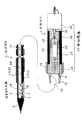
図1は本発明による針状超音波探触子の実施の形態を示す中央縦断面図である。この針状超音波探触子は、針先に設けた超音波変換器を被検体内の生体組織へ直接刺入して超音波の2次元走査により上記生体組織の超音波画像を収集するもので、図1に示すように、外針1及び内針2を有する針状部分(針状部)21と、本体部分(本体部)4とを備えている。
【0015】
上記外針1は、内針2を内側に保持して被検体の生体組織へ刺入する際のガイドをする部材となるもので、金属などの剛性材料で外径が1〜2mm程度の細径の中空パイプ状に形成されている。上記外針1の内側には、内針2が挿入されている。この内針2は、後述の超音波変換器3を外側面に保持して被検体の生体組織へ直接刺入するもので、金属などの剛性材料で外径が1〜2mm程度の細径の丸棒状に形成されると共に先端部5が円錐状に形成されており、上記外針1の内側に小さなクリアランスをあけて同軸状に挿入されて、図2に示すようにその軸周りに矢印Bのように回転可能及びその軸方向に矢印Cのように並進可能に設けられている。
【0016】
上記内針2の先端部5近傍の外側面には、超音波変換器3が設けられている。この超音波変換器3は、被検体内に超音波を打ち出すと共に生体組織から反射してきたエコー信号を受波するもので、図3に示すように、内針2の外側面の一部に溝6が形成されており、この溝6内に嵌め込んで固定されている。上記超音波変換器3は、サファイアやシリコンなどの音響レンズ材7をベースにして、この音響レンズ材7の一方の面8に下部電極9と圧電素子10と上部電極11とを設け、他方の面12には凹球面状に形成したレンズ面13を設けて成る。そして、上記下部電極9と圧電素子10と上部電極11とを駆動することにより、超音波14が発生され、この超音波14は上記レンズ面13で屈折して曲げられ、その屈折後の超音波14′は焦点15に収束するようになっている。なお、符号16は被検体を示し、符号17は図2に示すように内針2を矢印Bのように回転することにより上記焦点15によって得られる画像化領域を示している。また、図1に示すように、上記音響レンズ材7の一部に中間ベース18を搭載し、この中間ベース18と上記下部電極9、上部電極11とをそれぞれ信号線19でボンディングし、さらに上記中間ベース18にケーブル20を接続して図示外の制御装置に接続されている。
【0017】
そして、上記外針1の内側に内針2を挿入した全体で針状部分21を構成している。このような状態で、上記針状部分21を被検体16内に刺入し、超音波変換器3から超音波を被検体16内に送受波すると共に上記内針2を矢印Bのように回転及び矢印Cのように並進して2次元走査を行い、上記被検体16の生体組織の超音波画像を収集するようになっている。
【0018】
ここで、本発明においては、図1に示すように、上記本体部分4の内部に内針2の駆動機構22が設けられると共に、この本体部分4に上記針状部分21を着脱可能に組み合わせる着脱手段を備えている。まず、上記駆動機構22は、内針2を軸周りに回転させ或いはその軸方向に並進させるもので、回転アクチュエータ23と、第一可動ブロック24と、並進アクチュエータ25と、第二可動ブロック26とから成る。回転アクチュエータ23は、図2に示すように内針2をその軸周りに矢印B方向に回転させるもので、例えば小型の電気モータ等から成り、本体部分4の筒状体27の基端部に固定されている。上記回転アクチュエータ23の回転軸28には、第一可動ブロック24が取り付けられている。この第一可動ブロック24は、後述の第二可動ブロック26に対して上記回転アクチュエータ23の回転力をそのまま伝達するもので、先端部に噛み合い突部29を有している。
【0019】
また、上記回転アクチュエータ23の回転軸28には、並進アクチュエータ25が連結されている。この並進アクチュエータ25は、図2に示すように内針2をその軸方向に矢印Cのように並進させるもので、例えば前後方向の駆動力を発生する積層圧電体やモータの回転運動を直進運動に変更するリニアアクチュエータ等から成る。さらに、上記並進アクチュエータ25の先端部には、第二可動ブロック26が取り付けられている。この第二可動ブロック26は、前記内針2に回転アクチュエータ23の回転力と並進アクチュエータ25の直進運動とを共に伝達するもので、基端部に上記第一可動ブロック24の噛み合い突部29と係合する噛み合い凹部30を有している。そして、この噛み合い凹部30と上記噛み合い突部29とを噛み合わせると共に互いにスライド可能に係合するようになっている。このとき、上記噛み合い突部29と噛み合い凹部30との係合長さは、並進アクチュエータ25の直進運動の距離を吸収しうる長さとされている。
【0020】
次に、上記本体部分4に対する針状部分21の着脱可能の構造は、上記第二可動ブロック26の先端に、内針挟持片31が突設されると共にその内側面には接続端子32が設けられている。また、上記本体部分4の筒状体27の先端部には、外針挟持部33が延長して設けられると共に、その外針挟持部33の根元部には回転操作することにより該外針挟持部33の先端を開閉することができる固定用ノブ34が設けられている。ここで、上記内針挟持片31と外針挟持部33とで、上記針状部分21の内針2及び外針1の基端部をそれぞれ挟持する挟持部を構成し、上記接続端子32で、上記本体部分4と針状部分21とを電気的に接続する接続部を構成している。
一方、針状部分21の内針2の基端部には、上記内針挟持片31の接続端子32と接触する電極35が設けられている。そして、上記針状部分21の内針2の基端部を本体部分4の先端部に挿入し電極35を内針挟持片31の接続端子32に接触させると共に、外針1の基端部を外針挟持部33の内側に挿入し、固定用ノブ34を締め付けることにより該外針挟持部33の先端を閉めて、針状部分21を固定状態に装着する。また、この状態から、上記固定用ノブ34を緩めることにより該外針挟持部33の先端を拡げて、針状部分21を解放して外す。そして、上記内針挟持片31、外針挟持部33及び接続端子32並びに固定用ノブ34により、本体部分4に対して針状部分21を着脱可能とする着脱手段が構成されている。
【0021】
図4は図1に示す針状超音波探触子の関連発明としての超音波診断装置の実施の形態を示すブロック図である。この超音波診断装置は、超音波を利用して被検体の診断部位及び刺入部について超音波画像を得るもので、図4に示すように、探触子36と、超音波装置37と、モニタ38と、針状超音波探触子39と、画像処理部40とを備えて成る。
【0022】
上記探触子36は、被検体16表面に当接して操作し被検体16内に向けて超音波を送受波するもので、その内部には超音波を打ち出すと共に反射エコーを受信する超音波振動子が設けられている。超音波装置37は、上記探触子36を駆動して超音波を送受波させると共に収集した超音波画像信号を処理して被検体16内部の診断部位41の超音波断層像を作成するもので、その内部には送波回路、受波回路、対数圧縮回路、検波回路などが設けられている。モニタ38は、上記超音波装置37からの画像信号を取り込んで超音波断層像を表示する表示装置となるものである。また、針状超音波探触子39は、先端部が穿刺針状で外側面に超音波変換器を有し被検体16内に刺入して超音波の送受波を行うと共に走査を行って生体組織の超音波画像信号を収集するものである。
【0023】
さらに、画像処理部40は、上記針状超音波探触子39で収集した超音波画像信号を処理して診断部位41内の刺入部の超音波画像を作成するもので、図6に示すように、コネクタ42を介して針状超音波探触子39に送波駆動信号を供給する送波回路43と、上記針状超音波探触子39で受信し受波回路44で取り出した超音波受波信号をコネクタ45を介して入力し増幅するプリアンプ46と、このプリアンプ46からの超音波受波信号の信号レベルを最適化するゲイン調整部47と、カウンタ48の設定値に従って同期回路49により送波回路43を制御して超音波の送受波を繰り返すと共に上記ゲイン調整部47からの受波信号の積算を行う積算回路50と、コネクタ51を介して針状超音波探触子39の駆動機構22に駆動信号を送る駆動回路52と、バスライン53を介して上記積算回路50及び駆動回路52を一括制御するパーソナルコンピュータなどの制御回路部54と、上記積算回路50からの超音波画像信号について対数圧縮及び検波処理などを行う信号処理回路55とから成る。なお、この信号処理回路55からの出力信号は、コネクタ56を介してモニタ38に送られる。
【0024】
ここで、本発明の超音波診断装置においては、上記針状超音波探触子39として、図1に示すように本体部分4に駆動機構22が内蔵されると共にその本体部分4に対し針状部分21が着脱可能に組み合わされた針状超音波探触子が用いられている。また、上記画像処理部40の内部には、針状超音波探触子39の内針2を軸周りに回転させ或いはその軸方向に並進させる駆動機構22の駆動回路52を設けると共に、上記内針2の駆動と同期させて収集した超音波画像信号を積算する積算回路50を設け、かつ上記駆動回路52及び積算回路50の動作を制御する制御回路部54を設けたことが特徴である。
【0025】
そして、上記積算回路50の内部構成は、図7に示すように、入力した超音波受波信号について演算する第一の演算器57と、この第一の演算器57からの出力信号を記憶するメモリ部58と、このメモリ部58からの出力信号について演算する第二の演算器59との三段構成とされている。なお、図7において、第一のラッチ60は、上記第一の演算器57の演算結果を一時保存すると共に、メモリ部58へ送るものである。また、アドレス回路61は、上記メモリ部58への記録に先立って所定のアドレスデータを発生させるものである。さらに、第二のラッチ62は、上記メモリ部58から読み出されたデータを一時保存すると共に、第一の演算器57の別の入力部へ転送するものである。そして、制御回路63は、上記各構成要素の動作を制御するものである。
【0026】
次に、このような積算回路50の動作について、図8に示すタイムチャートを参照しながら説明する。まず、図7において、画像化処理された超音波受波信号は、所定ビットでA/D変換された後に第一の演算器57へ入力データD1,D2,…として入力する(図8(a))。次に、上記第一の演算器57で演算処理されたデータは、第一のラッチ60に一時保存されると共に、メモリ部58に送られて順次記録される。このとき、上記メモリ部58への記録に先立って、アドレス回路61は所定のアドレスデータA1,A2,…を発生させ(図8(c))、アドレスが確定すると既に記録済みのデータをメモリ部58から読み出すと共に、新しいデータを記録する。すなわち、制御回路63は、メモリ部58に対し図8(b)に示すようにリード、ライトを切り換え、該メモリ部58をいわゆるリードモディファイライトサイクルにて使用するように制御する。このリードモディファイライトサイクルは、同じアドレスA1,A2,…に対してアドレス保持時間の半分をデータ出力(リード)に、残り半分をデータ入力(ライト)にそれぞれ使用するものである。
【0027】
次に、上記アドレス確定後の前半の時間で、メモリ部58は予め記録されていたデータを図8(d)に示すD101,D102,…のように出力し、第二のラッチ62へ送る。第二のラッチ62はこれを一時保存してから図8(e)に示すD101 ,D102,…のように出力し、第一の演算器57の別の入力部へ転送する。すると、第一の演算器57は、入力したデータD101,D102,…について所定の演算を行い、その演算結果を第一のラッチ60に送る。以後、上述と同様にして処理が進み、第一の演算器57及びメモリ部58で積算されたデータが第二のラッチ62を介して第二の演算器59へ送られる。次に、第二の演算器59は、第二のラッチ62から出力されたデータを入力し、第一の演算器57による積算結果をその演算回数で除して規格化し、原データと同じビット長となるように処理する。その結果、第二の演算器59からは、図8(f)に示すように積算処理後のデータD201,D202,…が出力される。なお、上記第二の演算器59は、具体的には除算器などを用いれば実現可能であり、制御回路63で必要データを設定すればよい。
【0028】
以上のように、本発明では、積算回路50を第一の演算器57とメモリ部58と第二の演算器59との三段構成としたことにより、積算処理のための繰り返し演算回数を自由に設定でき、演算結果の規格化などと共にリアルタイムの積算処理を実現することができる。
【0029】
次に、このように構成された超音波診断装置の動作について説明する。まず、図4において、探触子36と超音波装置37とモニタ38とを用いて、被検体16内の診断部位41を観察しながら針状超音波探触子39の内針2を所望の刺入部まで誘導する。次に、上記刺入した針状超音波探触子39において、図3に示す上部電極11に超音波の送波電圧を印加して圧電素子10から所定周波数の超音波14を発生させ、音響レンズ材7のレンズ面13で超音波14′を屈折、収束させて焦点15を形成する。これと共に、上記焦点位置に対応する被検体16の生体組織からの反射エコーを上記と逆経路で圧電素子10に導いて受波信号を発生させ、この受波信号を図4に示す画像処理部40へ送って信号処理を行い、モニタ38上に刺入部の超音波画像を表示する。
【0030】
このとき、図5に示すように、上記モニタ38の画面には、被検体16内部の診断部位41の超音波断層像64と上記診断部位41の刺入部の超音波画像(針先像)65とが同時に表示される。このような状態で、図4において探触子36及び針状超音波探触子39で超音波の送受波を行いながら、図1に示す駆動機構22を操作して図2に示すように内針2を画像化領域17に沿って矢印B,Cのように回転及び並進操作することにより、リアルタイムに生体組織の細胞レベルでの超音波画像を得ることができる。この場合、図6に示す制御回路部54は、針状超音波探触子39の内針2を軸周りに回転させ或いはその軸方向に並進させる動作を間歇的に行いながら、その停止期間内に上記針状超音波探触子39による所定回数の超音波の送受波を繰り返すと共に受波信号を積算処理するように制御する。
【0031】
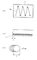
図9は、上記制御回路部54による針状超音波探触子39の移動操作と超音波信号の送受波の積算との関係を示す動作タイミングの説明図である。図1に示す駆動機構22による回転及び並進操作により、使用している超音波の周波数から得られる分解能と同等かそれより小さいステップ間隔で内針2を移動するときの画像化領域17(図2参照)上での超音波の焦点15の軌跡は、図9(a)に示すようになる。この図9(a)において、符号66はステップ的に回転するときの間隔を示し、符号67は上記ステップ的に回転した後の停止状態を示し、符号68はいくつかステップ的に回転(66)した後にステップ的に並進するときの間隔を示している。
【0032】
また、上記駆動機構22によりステップ的に移動を行った際に、その停止状態67で所定回数の超音波の送受波と積算処理を行う動作は、図9(b)に示すようになる。図9(b)の動作タイミングにおいて、領域aは上記ステップ的に回転する移動時(66)を示し、領域bは上記ステップ的に回転した後の停止時(67)を示し、符号69は上記領域bにおいて間隔cで超音波の送波・受波並びに受波信号の積算を行うタイミングを示している。さらに、領域dは上記ステップ的に回転(66)した後にステップ的に並進する移動時(68)を示している。この場合、超音波の送波・受波並びに受波信号の積算を上記の動作タイミングで領域bの停止時に所定の回数だけ実行することにより、反射率が小さい場合でも効率よく信号強度の大きい受波信号を得ることができる。従って、S/Nの高い信号を得ることができ、受波信号が小さい場合でも高画質の超音波画像が得られる。
【0033】
図10は、上記針状超音波探触子39の移動操作と超音波信号の送受波の積算との関係の他の例を示す動作タイミングの説明図である。この場合、図6に示す制御回路部54は、針状超音波探触子39の内針2を軸周りに回転させ或いはその軸方向に並進させる動作を連続的に行いながら、上記針状超音波探触子39による超音波の送受波を繰り返すと共に所定回数の受波信号を積算処理するように制御する。図1に示す駆動機構22による回転及び並進操作により、連続して内針2を移動するときの画像化領域17(図2参照)上での超音波の焦点15の軌跡は、図10(a)に示すようになる。この図10(a)において、符号70は例えば鋸刃状に連続して往復移動する軌跡を示している。
【0034】
また、上記駆動機構22により連続して移動を行った際に、その移動状態70で所定回数の超音波の送受波と積算処理を行う動作は、図10(b)に示すようになる。図10(b)の動作タイミングにおいて、符号71は間隔cで超音波の送波・受波並びに受波信号の積算を行うタイミングを示している。このとき、図10(c)に示すように、超音波の周波数と音速と超音波レンズのF数とから得られる焦点位置でのスポット径をdとし、駆動機構22の動作速度をvとすると、t=d/vの時間内にできるだけ多くの送波・受波並びに受波信号の積算を実行して、上記スポット径dのオーバーラップを多くするようにすればよい。このように、超音波の送波・受波並びに受波信号の積算を上記の動作タイミングで所定の回数だけ実行することにより、反射率が小さい場合でも効率よく信号強度の大きい受波信号を得ることができる。従って、S/Nの高い信号を得ることができ、受波信号が小さい場合でも高画質の超音波画像が得られる。
【0035】
なお、図示はしていないが、上記制御回路部54の制御において、針状超音波探触子39の内針2を軸周りに回転させ或いはその軸方向に並進させる動作を間歇的に行う走査速度と超音波受波信号の積算密度、又は針状超音波探触子39の内針2を軸周りに回転させ或いはその軸方向に並進させる動作を連続的に行う走査速度と超音波受波信号の積算密度をそれぞれ可変にしてもよい。この場合は、試料組織の密度及び反射信号強度の程度に合わせて走査速度と超音波受波信号の積算密度を選択することにより、画像化時間或いは解像度の制御を行うことが可能である。すなわち、試料組織の密度がラフな場合や反射信号強度が大きい場合或いは解像度を必要としない場合には、図9においてステップ間隔を大きくしたり積算回数を減らし、また図10において移動速度を早くしたり超音波の送波・受波並びに受波信号の積算のタイミングを長くすればよい。
【0036】
なお、以上において、図5に示すモニタ38の画面に表示する針先像65としては、刺入部の正常組織の画像65aと、異常組織の画像65bとを並べて表示してもよい。
【0037】
【発明の効果】
本発明による針状超音波探触子(図1参照)は以上のように構成されたので、中空パイプ状に形成された外針と、この外針の内側に軸周りに回転可能及び軸方向に並進可能に挿入された内針と、この内針の先端部近傍の外側面に設けられ超音波を送受波する超音波変換器とを有する針状部と;上記内針をその軸周りに回転させ及びその軸方向に並進させる駆動機構を内蔵した本体部とを;該本体部の先端部に設けられ、針状部の内針及び外針の基端部をそれぞれ挟持する挟持部と、本体部と針状部とを電気的に接続する接続部とを有する着脱手段で、上記本体部と針状部とを着脱することができる。このように、内針をその軸周りに回転させ及びその軸方向に並進させる駆動機構を内蔵した本体部に対し、被検体内に刺入する内針及び外針を有する針状部を着脱手段で着脱可能に組み合わせたことにより、生体組織へ直接刺入する針状部を被検体毎に容易に交換することができる。従って、従来のように針状部を十分に消毒してから再使用する必要はなく、取り扱いが容易であると共に、被検体に対する安全性を向上することができる。
【0038】
また、関連発明としての超音波診断装置(図4参照)は以上のように構成されたので、被検体表面に当接して操作し被検体内に向けて超音波を送受波すると共に走査を行って診断部位の断層像信号を収集する探触子と、先端部が穿刺針状で外側面に超音波変換器を有し被検体内に刺入して超音波の送受波を行うと共に走査を行って生体組織の超音波画像信号を収集する針状超音波探触子とを有して成る超音波診断装置において、上記針状超音波探触子として請求項1記載の針状超音波探触子を用い、その針状超音波探触子がわの画像処理部内には、針状超音波探触子の内針をその軸周りに回転させ及びその軸方向に並進させる駆動機構の駆動回路と、上記内針の駆動と同期させて収集した超音波画像信号を積算する積算回路と、上記駆動回路及び積算回路の動作を制御する制御回路部とを設けたことで、超音波の送波・受波並びに受波信号の積算を所定の回数だけ実行することにより、反射率が小さい場合でも効率よく信号強度の大きい受波信号を得ることができる。従って、S/Nの高い信号を得ることができ、受波信号が小さい場合でも高画質の超音波画像が得られる。また、上記表示装置には被検体内部の超音波断層像と刺入部の超音波画像とを同時に表示することができるので、瞬時に病変を確定することができる。これにより、被検体内部の診断部位と刺入部との位置関係が直ちに分かり、診断及び治療が正確かつスムーズにできる。
【図面の簡単な説明】
【図1】 本発明による針状超音波探触子の実施の形態を示す中央縦断面図である。
【図2】 針状部分の内針の回転及び並進の2次元走査を示す説明図である。
【図3】 図1のA−A線拡大断面図である。
【図4】 図1に示す針状超音波探触子の関連発明としての超音波診断装置の実施の形態を示すブロック図である。
【図5】 モニタにおける超音波画像の表示例を示す説明図である。
【図6】 上記超音波診断装置における画像処理部の内部構成を示すブロック図である。
【図7】 上記画像処理部における積算回路の内部構成を示すブロック図である。
【図8】 上記積算回路の動作を示すタイムチャートである。
【図9】 制御回路部による針状超音波探触子の移動操作と超音波信号の送受波の積算との関係を示す動作タイミングの説明図である。
【図10】 上記針状超音波探触子の移動操作と超音波信号の送受波の積算との関係の他の例を示す動作タイミングの説明図である。
【符号の説明】
1…外針
2…内針
3…超音波変換器
4…本体部分
5…先端部
16…被検体
21…針状部分
22…駆動機構
23…回転アクチュエータ
24…第一可動ブロック
25…並進アクチュエータ
26…第二可動ブロック
31…内針挟持片
33…外針挟持部
36…探触子
37…超音波装置
38…モニタ
39…針状超音波探触子
40…画像処理部
41…診断部位
50…積算回路
52…駆動回路
54…制御回路部[0001]
BACKGROUND OF THE INVENTION
The present invention provides a needle-like ultrasonic probe that directly inserts an ultrasonic transducer provided at a needle tip into a living tissue in a subject and collects an ultrasonic image of the living tissue by two-dimensional scanning of the ultrasonic wave. In particular, the needle-like portion directly inserted into the living tissue can be attached and detached to improve the safety of the subject, improve the S / N of the collected ultrasonic image signal, and add the subject to the display device. InsideUltrasonic tomogramThe present invention relates to a needle-like ultrasonic probe that can simultaneously display an ultrasonic image of an insertion portion and an ultrasonic diagnostic apparatus using the same.
[0002]
[Prior art]
As a method for diagnosing a lesion occurring in each part of a body cavity, a biopsy (biopsy) is generally performed. This is done by inserting an puncture needle to a predetermined location while imaging the lesion in the body cavity using an ultrasonic diagnostic device, and capturing and collecting a part of the biological tissue of the lesion within the tip of the needle and creating an observation sample. The disease name is diagnosed by discrimination under an optical microscope. However, this method requires a long time for diagnosis because it is necessary to perform various treatments after the biological tissue is removed from the body, and various processing is applied to the sample. There was a problem that there was a risk of changing from the state of. In response to these circumstances, in recent years, an ultrasonic transducer that attaches an ultrasonic transducer to a puncture needle and directly punctures the lesion, examines the tissue properties of the lesion, or images surrounding living tissue Probes have been proposed in, for example, Japanese Patent Publication No. 4-78299 and Japanese Patent Publication No. 5-9097.
[0003]
Such a conventional needle-like ultrasonic probe is formed in the shape of a thin round rod with a rigid material inside the outer needle formed of a rigid material in the shape of a thin hollow pipe, and the tip is conical. The inner needle formed in a shape is inserted so as to be rotatable about its axis and to be able to translate in the axial direction, and an ultrasonic transducer for transmitting and receiving ultrasonic waves is provided on the outer surface near the tip of the inner needle. The inner needle and the outer needle are inserted into the subject, ultrasonic waves are transmitted and received from the ultrasonic transducer, and the inner needle is rotated and translated two-dimensionally to perform an ultrasonic image of the living tissue. Was supposed to collect.
[0004]
[Problems to be solved by the invention]
However, in such a conventional needle-like ultrasonic probe, the needle-like portion having the inner needle and the outer needle inserted into the subject is not removable, and the needle is different for each different subject. Therefore, the needle-shaped part must be fully sterilized when reused, and it is not easy to handle and pays close attention to safety. It was something that had to be paid.
[0005]
In order to diagnose the tissue characterization of a lesion using a needle-like ultrasound probe, it is effective to perform the method directly from the ultrasound image of the lesion. Therefore, a high resolution of at least about several μm to several tens of μm is required. Therefore, it is essential that the center frequency of the transmission / reception wave of the ultrasonic transducer be a high frequency of several tens of MHz to several hundreds of MHz, and it is necessary to make the vibrator thin. Further, in order to reduce the invasiveness to a living body, it is necessary to suppress the needle-like portion to about 1 mm in diameter, so it is difficult to mount a large number of ultrasonic transducers. For this reason, it is considered effective to scan an ultrasonic transducer using a thin film transducer, but because the transducer is a thin film, a large voltage cannot be applied due to the limitation of dielectric strength, and the ultrasonic power is reduced. The ultrasonic wave reception signal is small because it cannot be increased and the reflectance due to the difference in acoustic impedance at the cellular level inside the living body is expected to be very small compared to the average reflectance of the living body. The S / N required for imaging could not be obtained.
[0006]
Furthermore, in the ultrasonic diagnostic apparatus using the needle-like ultrasonic probe as described above, the diagnostic site inside the subject was obtained with a normal probe.Ultrasonic tomogram(B-mode image) and an ultrasonic image (needle tip image) obtained for the insertion portion with a needle-like ultrasonic probe or inside the subjectUltrasonic tomogramAnd ultrasonic images of normal tissue and abnormal tissue of the insertion portion are not simultaneously displayed on the screen of the display device. Therefore, the positional relationship between the diagnostic site inside the subject and the insertion site is not immediately known, and it is not possible to know how the abnormal tissue of the insertion site is different from the normal tissue, so diagnosis and treatment can be performed accurately and smoothly. There was something I couldn't do.
[0007]
Accordingly, the present invention addresses such problems, improves the safety of the subject by making the needle-like portion directly inserted into the living tissue removable, and the S / N ratio of the collected ultrasonic image signal. Can be improved and the display device has aUltrasonic tomogramIt is an object of the present invention to provide a needle-like ultrasonic probe that can simultaneously display the ultrasonic image of the insertion portion and an ultrasonic diagnostic apparatus using the needle-like ultrasonic probe.
[0008]
[Means for Solving the Problems]
In order to achieve the above object, a needle-like ultrasonic probe according to the present invention comprises:InsideInsert the needle and outer needle into the subject.SuperIn a needle-like ultrasonic probe that transmits and receives ultrasonic waves from a sound wave transducer and collects ultrasonic image signals of a living tissue by performing two-dimensional scanning of the inner needle by rotation and translation,An outer needle formed in the shape of a hollow pipe, and is inserted into the outer needle so as to be rotatable around the axis and translated in the axial direction. A needle-like portion having an inner needle formed and an ultrasonic transducer that is provided on the outer surface in the vicinity of the tip of the inner needle and transmits and receives ultrasonic waves;The inner needleThatRotate around the axisas well asBuilt-in drive mechanism to translate in the axial directionBody partWhen,The main body portion includes a pinching portion for holding the inner end of the needle-like portion and the proximal end portion of the outer needle at the distal end thereof, and a connection for electrically connecting the main body portion and the needle-like portion. A main body part and a needle-like partAnd an attaching / detaching means for attaching and detaching.
[0009]
In addition, an ultrasonic diagnostic apparatus as a related invention is a probe that operates by contacting a subject surface and transmits / receives ultrasonic waves into the subject, and transmits / receives ultrasonic waves by driving the probe. An ultrasonic device for generating an ultrasonic tomographic image inside the subject by processing the ultrasonic image signal collected while being waved, and a display device for displaying the ultrasonic tomographic image by capturing the image signal from the ultrasonic device; A needle-like tip that has a puncture needle shape, has an ultrasonic transducer on the outer surface, and inserts into a subject to transmit and receive ultrasonic waves and scan to collect ultrasonic image signals of living tissue In an ultrasonic diagnostic apparatus comprising: an ultrasonic probe; and an image processing unit that processes an ultrasonic image signal collected by the needle-like ultrasonic probe and creates an ultrasonic image of a puncture unit. The needle-shaped ultrasonic probe according to claim 1 is used as the needle-shaped ultrasonic probe, and the image is displayed. In the processing section, the inner needle of the needle ultrasonic probeThatRotate around the axisas well asDrive circuit for drive mechanism that translates in the axial directionWhenAn integration circuit for integrating the ultrasonic image signals collected in synchronization with the driving of the inner needleWhen, A control circuit unit for controlling the operation of the driving circuit and the integrating circuitWhenAnd an ultrasonic tomographic image inside the subject and an ultrasonic image of the insertion portion are simultaneously displayed on the display device.
[0010]
Note that the control circuit unit that controls the operation of the drive circuit and the integration circuit controls the inner needle of the needle-like ultrasonic probe.ThatRotate around the axisas well asWhile intermittently performing the operation of translating in the axial direction, the ultrasonic wave transmission / reception of the needle-like ultrasonic probe is repeated a predetermined number of times during the stop period and the reception signal is integrated. Good.
[0011]
In addition, the control circuit unit that controls the operation of the drive circuit and the integration circuit controls the inner needle of the needle-like ultrasonic probe.ThatRotate around the axisas well asWhile continuously performing the translation in the axial direction,In the imaging region of the ultrasonic transducer within the time obtained by dividing the spot diameter at the focal position of the ultrasonic transducer by the operating speed of the drive mechanism,It is also possible to repeat the ultrasonic wave transmission / reception by the needle-like ultrasonic probe and to integrate the reception signal a predetermined number of times.
[0012]
Furthermore, the control circuit unit that controls the operation of the drive circuit and the integration circuit intermittently performs the operation of rotating the inner needle of the needle-like ultrasonic probe around its axis and translating it in the axial direction. And integration of ultrasonic wave reception signals for a specified number of times when intermittently stopped, variable by changing intermittent step intervals or changing the number of integrations, or within the acicular ultrasonic probe The scanning speed for continuously rotating the needle around its axis and the translation in the axial direction and the integration of the ultrasonic wave reception signal are the spot diameter at the focal point of the ultrasonic transducer based on the operating speed of the drive mechanism. The accumulated density performed within the divided time is changed by changing the moving speed.Or changing the timing of ultrasonic wave transmission / reception and integration of received signalsYou may make it variable.
[0013]
The integration circuit includes a first computing unit that computes an input ultrasonic wave reception signal, a memory unit that stores an output signal from the first computing unit, and an output signal from the memory unit. A three-stage configuration with a second computing unitThe data processed by the first arithmetic unit is sequentially recorded in the memory unit, and the recorded data is read out and transferred to the first arithmetic unit again to perform a predetermined calculation. The data accumulated in the computing unit and the memory unit is sent to the second computing unit, and the result of integration by the first computing unit is divided by the number of computations to be normalized.May be.
[0014]
DETAILED DESCRIPTION OF THE INVENTION
Hereinafter, embodiments of the present invention will be described in detail with reference to the accompanying drawings.
FIG. 1 is a central longitudinal sectional view showing an embodiment of a needle-like ultrasonic probe according to the present invention. This needle-shaped ultrasonic probe is a device that directly inserts an ultrasonic transducer provided at the needle tip into a living tissue in a subject and collects an ultrasonic image of the living tissue by two-dimensional scanning of the ultrasonic wave. Then, as shown in FIG. 1, a needle-like portion having an outer needle 1 and an inner needle 2(Needle part)21 and body part(Main body)4 is provided.
[0015]
The outer needle 1 is a member that holds the
[0016]
An
[0017]
And the needle-like part 21 is comprised by the whole which inserted the
[0018]
Here, in the present invention, as shown in FIG. 1, a
[0019]
A
[0020]
Next, the detachable structure of the needle-like part 21 with respect to the main body part 4 is such that an inner
On the other hand, an
[0021]
FIG. 4 is a block diagram showing an embodiment of an ultrasonic diagnostic apparatus as a related invention of the needle-like ultrasonic probe shown in FIG. This ultrasonic diagnostic apparatus obtains an ultrasonic image of a diagnostic part and a puncture part of a subject using ultrasonic waves, and as shown in FIG. 4, a
[0022]
The
[0023]
Further, the
[0024]
Here, in the ultrasonic diagnostic apparatus of the present invention, the
[0025]
And aboveIntegration circuitAs shown in FIG. 7, the internal configuration of 50 includes a first computing unit 57 that computes an inputted ultrasonic wave reception signal, a
[0026]
Then like thisIntegration circuitThe operation of 50 will be described with reference to the time chart shown in FIG. First, in FIG. 7, the ultrasonic wave reception signal subjected to the imaging process is A / D converted by a predetermined bit and then input data D to the first computing unit 57.1, D2,... (FIG. 8A). Next, the data processed by the first calculator 57 is temporarily stored in the
[0027]
Next, in the first half time after the address determination, the
[0028]
As described above, in the present invention,Integration circuit50 has a three-stage configuration of a first computing unit 57, a
[0029]
Next, the operation of the thus configured ultrasonic diagnostic apparatus will be described. First, in FIG. 4, the
[0030]
At this time, as shown in FIG. 5, on the screen of the
[0031]
FIG. 9 shows the operation of moving the needle-shaped
[0032]
In addition, when the
[0033]
FIG. 10 shows the operation of moving the needle-like
[0034]
Further, when the
[0035]
Although not shown, in the control of the
[0036]
In the above, as the
[0037]
【The invention's effect】
Since the needle-like ultrasonic probe (see FIG. 1) according to the present invention is configured as described above,An outer needle formed in the shape of a hollow pipe, an inner needle inserted inside the outer needle so as to be rotatable around the axis and translated in the axial direction, and an outer needle provided on the outer surface near the tip of the inner needle. A needle-like portion having an ultrasonic transducer for transmitting and receiving sound waves; and a main body portion incorporating a drive mechanism for rotating the inner needle around its axis and translating in the axial direction; And a detachable means for holding the inner and outer needles of the needle-like part, and a connecting part for electrically connecting the main part and the needle-like part. And the needle-shaped part can be attached and detached. in this way,Inner needleThatRotate around the axisas well asBuilt-in drive mechanism to translate in the axial directionBody partIn contrast, it has an inner needle and an outer needle that are inserted into the subject.NeedleCan be inserted directly into the living tissue by detachably combining withNeedleCan be easily exchanged for each subject. Therefore, as beforeNeedleFully disinfectFromThere is no need to re-use, the handling is easy, and the safety for the subject can be improved.
[0038]
In addition, since the ultrasonic diagnostic apparatus as a related invention (see FIG. 4) is configured as described above, the ultrasonic diagnostic apparatus is operated in contact with the subject surface to transmit and receive ultrasonic waves toward the subject and perform scanning. A probe that collects tomographic image signals of the diagnostic site, and the tip is a puncture needle with an ultrasonic transducer on the outer surface, and is inserted into the subject to transmit and receive ultrasonic waves and scan An ultrasonic diagnostic apparatus comprising: a needle-like ultrasonic probe for performing acquisition of an ultrasonic image signal of a living tissue, as the needle-like ultrasonic probeClaim 1The needle-like ultrasonic probe is used, and the needle-like ultrasonic probe has an inner needle in the image processing section.ThatRotate around the axisas well asDrive circuit for drive mechanism that translates in the axial directionWhenAn integration circuit for integrating the ultrasonic image signals collected in synchronization with the driving of the inner needleWhen, A control circuit unit for controlling the operation of the driving circuit and the integrating circuitWhenHaving establishedsoBy executing ultrasonic wave transmission / reception and integration of received signals a predetermined number of times, a received signal having a high signal intensity can be obtained efficiently even when the reflectance is small. Therefore, a signal with a high S / N can be obtained, and a high-quality ultrasonic image can be obtained even when the received signal is small. Moreover, since the ultrasonic tomographic image inside the subject and the ultrasonic image of the insertion portion can be displayed simultaneously on the display device, the lesion can be determined instantaneously. As a result, the positional relationship between the diagnostic site inside the subject and the insertion portion can be immediately understood, and diagnosis and treatment can be performed accurately and smoothly.
[Brief description of the drawings]
FIG. 1 is a central longitudinal sectional view showing an embodiment of a needle-like ultrasonic probe according to the present invention.
FIG. 2 is an explanatory diagram showing two-dimensional scanning of rotation and translation of an inner needle of a needle-like portion.
FIG. 3 is an enlarged cross-sectional view taken along line AA in FIG.
4 is a block diagram showing an embodiment of an ultrasonic diagnostic apparatus as a related invention of the needle-like ultrasonic probe shown in FIG. 1. FIG.
FIG. 5 is an explanatory diagram showing a display example of an ultrasonic image on a monitor.
FIG. 6 is a block diagram showing an internal configuration of an image processing unit in the ultrasonic diagnostic apparatus.
FIG. 7 shows the image processing unit.Integration circuitIt is a block diagram which shows the internal structure.
[Figure 8]Integration circuitIt is a time chart which shows this operation | movement.
FIG. 9 shows the operation of moving the needle-like ultrasonic probe by the control circuit unit and the transmission and reception of ultrasonic signals.TotalIt is explanatory drawing of the operation timing which shows the relationship.
FIG. 10 shows the moving operation of the needle-like ultrasonic probe and the transmission and reception of ultrasonic signals.TotalIt is explanatory drawing of the operation | movement timing which shows the other example of a relationship.
[Explanation of symbols]
1 ... Outer needle
2 ... Inner needle
3. Ultrasonic transducer
4. Body part
5 ... Tip
16 ... Subject
21 ... acicular part
22 ... Drive mechanism
23 ... Rotary actuator
24. First movable block
25 ... Translational actuator
26 ... Second movable block
31 ... Inner needle clamping piece
33 ... outer needle clamping part
36 ... Probe
37 ... Ultrasonic device
38 ... Monitor
39 ... acicular ultrasonic probe
40. Image processing unit
41 ... Diagnosis site
50 ...Integration circuit
52 ... Drive circuit
54. Control circuit section
Claims (6)
中空パイプ状に形成された外針と、この外針の内側に軸周りに回転可能及び軸方向に並進可能に挿入され剛性材料で細径の丸棒状に形成されると共に先端部が円錐状に形成された内針と、この内針の先端部近傍の外側面に設けられ超音波を送受波する超音波変換器とを有する針状部と、
上記内針をその軸周りに回転させ及びその軸方向に並進させる駆動機構を内蔵した本体部と、を備え、
上記本体部は、その先端部に、上記針状部の内針及び外針の基端部をそれぞれ挟持する挟持部と、上記本体部と針状部とを電気的に接続する接続部とを有し、該本体部と針状部とを着脱する着脱手段を備えたことを特徴とする針状超音波探触子。The inner needle and the outer needle by performing two-dimensional scanning of the rotation and translation of the inner needle with the ultrasound from the ultrasound transducer to transmit and receive waves to penetrate into the object to acquire ultrasound image signals of the biological tissue In a needle-like ultrasonic probe,
An outer needle formed in the shape of a hollow pipe, and is inserted into the outer needle so as to be rotatable around the axis and translated in the axial direction. A needle-like portion having an inner needle formed and an ultrasonic transducer that is provided on the outer surface in the vicinity of the tip of the inner needle and transmits and receives ultrasonic waves;
And a main body portion having a built-in drive mechanism for translating rotates and in the axial direction about its axis of the inner needle,
The main body portion includes a pinching portion that sandwiches the proximal end portion of the inner needle and the outer needle of the needle-like portion, and a connection portion that electrically connects the main body portion and the needle-like portion to the distal end portion thereof. A needle-like ultrasonic probe comprising an attachment / detachment means for attaching / detaching the main body part and the needle-like part .
上記針状超音波探触子として請求項1記載の針状超音波探触子を用い、
上記画像処理部内には、針状超音波探触子の内針をその軸周りに回転させ及びその軸方向に並進させる駆動機構の駆動回路と、上記内針の駆動と同期させて収集した超音波画像信号を積算する積算回路と、上記駆動回路及び積算回路の動作を制御する制御回路部とを設け、
上記表示装置に被検体内部の超音波断層像と刺入部の超音波画像とを同時に表示するようにしたことを特徴とする超音波診断装置。A probe that touches the surface of the subject and operates to send and receive ultrasonic waves into the subject, drives the probe to send and receive ultrasonic waves, and processes collected ultrasound image signals An ultrasonic device that creates an ultrasonic tomographic image inside the subject, a display device that captures an image signal from the ultrasonic device and displays an ultrasonic tomographic image, and a distal end with a puncture needle shape that is superficial on the outer surface A needle-like ultrasonic probe that has a sound wave transducer and inserts into a subject to transmit and receive ultrasonic waves and scans to collect ultrasonic image signals of living tissue, and the needle-like ultrasonic waves In an ultrasonic diagnostic apparatus comprising an image processing unit that processes an ultrasonic image signal collected by a probe and creates an ultrasonic image of a puncture unit,
The needle-like ultrasonic probe according to claim 1 is used as the needle-like ultrasonic probe,
The aforementioned image processing portion, a drive circuit of the needle-shaped ultrasonic probe of the inner needle is rotated about its axis and a drive mechanism for translating in the axial direction, and collected in synchronization with the drive of the inner needle ultra a integrating circuit for integrating the acoustic image signals, and a control circuit for controlling the operation of the driving circuit and the integrated circuit is provided,
An ultrasonic diagnostic apparatus characterized in that an ultrasonic tomographic image inside a subject and an ultrasonic image of an insertion portion are simultaneously displayed on the display device.
針状超音波探触子の内針をその軸周りに回転させ及びその軸方向に並進させる動作を間歇的に行う走査速度と超音波受波信号の積算を間歇的な停止時に所定回数だけ実行する積算密度を、間歇的なステップ間隔を変えたり積算回数を変えることで可変にし、
又は針状超音波探触子の内針をその軸周りに回転させ及びその軸方向に並進させる動作を連続的に行う走査速度と超音波受波信号の積算を超音波変換器の焦点位置でのスポット径を駆動機構の動作速度で除した時間内に行う積算密度を、移動速度を変えること又は超音波の送波・受波並びに受波信号の積算のタイミングを変えることで可変にした、
ことを特徴とする請求項3又は4記載の超音波診断装置。The control circuit unit for controlling the operation of the driving circuit and the integrating circuit is:
Accumulation of the ultrasonic wave reception signal and the scanning speed that intermittently performs the operation of rotating the inner needle of the needle-shaped ultrasonic probe around its axis and translating in the axial direction is executed a predetermined number of times when intermittently stopped. The integration density to be made variable by changing the intermittent step interval or the number of integrations,
Alternatively, the integral of the scanning speed and ultrasonic wave reception signal at the focal position of the ultrasonic transducer is a continuous operation of rotating the inner needle of the needle-like ultrasonic probe around its axis and translating in the axial direction. of the integrated density to be performed divided by the time the operating speed of the spot diameter a drive mechanism, and the variable by changing the timing of the integration of the transmitting-reception and received signals of Rukoto or ultrasonic changing the moving speed ,
The ultrasonic diagnostic apparatus according to claim 3 or 4, wherein
Priority Applications (1)
| Application Number | Priority Date | Filing Date | Title |
|---|---|---|---|
| JP15816496A JP3929524B2 (en) | 1996-06-19 | 1996-06-19 | Needle-like ultrasonic probe and ultrasonic diagnostic apparatus using the same |
Applications Claiming Priority (1)
| Application Number | Priority Date | Filing Date | Title |
|---|---|---|---|
| JP15816496A JP3929524B2 (en) | 1996-06-19 | 1996-06-19 | Needle-like ultrasonic probe and ultrasonic diagnostic apparatus using the same |
Publications (2)
| Publication Number | Publication Date |
|---|---|
| JPH105217A JPH105217A (en) | 1998-01-13 |
| JP3929524B2 true JP3929524B2 (en) | 2007-06-13 |
Family
ID=15665675
Family Applications (1)
| Application Number | Title | Priority Date | Filing Date |
|---|---|---|---|
| JP15816496A Expired - Fee Related JP3929524B2 (en) | 1996-06-19 | 1996-06-19 | Needle-like ultrasonic probe and ultrasonic diagnostic apparatus using the same |
Country Status (1)
| Country | Link |
|---|---|
| JP (1) | JP3929524B2 (en) |
Families Citing this family (1)
| Publication number | Priority date | Publication date | Assignee | Title |
|---|---|---|---|---|
| JP5319355B2 (en) * | 2009-03-27 | 2013-10-16 | 高嶋技研株式会社 | Ultrasonic flaw detector for hand testing |
-
1996
- 1996-06-19 JP JP15816496A patent/JP3929524B2/en not_active Expired - Fee Related
Also Published As
| Publication number | Publication date |
|---|---|
| JPH105217A (en) | 1998-01-13 |
Similar Documents
| Publication | Publication Date | Title |
|---|---|---|
| JP3723663B2 (en) | Ultrasonic diagnostic equipment | |
| JPH10118072A (en) | Intra-celom ultrasonic probe apparatus | |
| WO2006028249A1 (en) | Ultrasonic probe, ultrasonograph, and ultrasonography | |
| JP3114553B2 (en) | Ultrasound diagnostic equipment | |
| JPH08117237A (en) | Ultrasonic diagnostic device | |
| WO2008041323A1 (en) | Ultrasonic image processing device, and ultrasonic diagnosing device | |
| JP4533615B2 (en) | Puncture needle and ultrasonic endoscope system | |
| CN115251993A (en) | Miniature multi-frequency array type ultrasonic transducer, multi-frequency ultrasonic three-dimensional imaging probe and imaging method thereof | |
| JP5274854B2 (en) | Ultrasonic diagnostic equipment | |
| WO2010050555A1 (en) | Ultrasonic wave observation device | |
| JP2006255015A (en) | Ultrasonic probe, adaptor for ultrasonic probe, and ultrasonic diagnostic equipment | |
| JP4672386B2 (en) | Ultrasonic probe and ultrasonic diagnostic system | |
| JP3929524B2 (en) | Needle-like ultrasonic probe and ultrasonic diagnostic apparatus using the same | |
| JP4074169B2 (en) | Ultrasonic transceiver unit | |
| JP4119530B2 (en) | Endoscope device and position detection catheter inserted into endoscope | |
| JP5109070B2 (en) | Ultrasound image display device, ultrasound image display method, endoscopic surgery support system, ultrasound image display program | |
| JPH059097B2 (en) | ||
| JP3676453B2 (en) | Acicular ultrasonic probe | |
| JP3483053B2 (en) | Needle-like ultrasonic probe and ultrasonic diagnostic imaging apparatus using the same | |
| JP2007082629A (en) | Ultrasonic probe | |
| JP4624883B2 (en) | Ultrasonic image processing apparatus and ultrasonic diagnostic apparatus | |
| JP4383108B2 (en) | Ultrasonic diagnostic equipment | |
| JPH10248851A (en) | Ultrasonic endoscope | |
| JP2551397Y2 (en) | Ultrasound diagnostic equipment | |
| JP2008104497A (en) | Method and apparatus for visualizing fine blood vessel using ultrasonic waves |
Legal Events
| Date | Code | Title | Description |
|---|---|---|---|
| A131 | Notification of reasons for refusal |
Free format text: JAPANESE INTERMEDIATE CODE: A131 Effective date: 20051213 |
|
| A521 | Written amendment |
Free format text: JAPANESE INTERMEDIATE CODE: A523 Effective date: 20060210 |
|
| A131 | Notification of reasons for refusal |
Free format text: JAPANESE INTERMEDIATE CODE: A131 Effective date: 20060530 |
|
| A521 | Written amendment |
Free format text: JAPANESE INTERMEDIATE CODE: A523 Effective date: 20060728 |
|
| A131 | Notification of reasons for refusal |
Free format text: JAPANESE INTERMEDIATE CODE: A131 Effective date: 20061010 |
|
| A521 | Written amendment |
Free format text: JAPANESE INTERMEDIATE CODE: A523 Effective date: 20061211 |
|
| TRDD | Decision of grant or rejection written | ||
| A01 | Written decision to grant a patent or to grant a registration (utility model) |
Free format text: JAPANESE INTERMEDIATE CODE: A01 Effective date: 20070306 |
|
| A61 | First payment of annual fees (during grant procedure) |
Free format text: JAPANESE INTERMEDIATE CODE: A61 Effective date: 20070307 |
|
| R150 | Certificate of patent or registration of utility model |
Free format text: JAPANESE INTERMEDIATE CODE: R150 |
|
| FPAY | Renewal fee payment (event date is renewal date of database) |
Free format text: PAYMENT UNTIL: 20110316 Year of fee payment: 4 |
|
| FPAY | Renewal fee payment (event date is renewal date of database) |
Free format text: PAYMENT UNTIL: 20110316 Year of fee payment: 4 |
|
| FPAY | Renewal fee payment (event date is renewal date of database) |
Free format text: PAYMENT UNTIL: 20130316 Year of fee payment: 6 |
|
| FPAY | Renewal fee payment (event date is renewal date of database) |
Free format text: PAYMENT UNTIL: 20140316 Year of fee payment: 7 |
|
| LAPS | Cancellation because of no payment of annual fees |