JP3925144B2 - Recording method and recording medium - Google Patents
Recording method and recording medium Download PDFInfo
- Publication number
- JP3925144B2 JP3925144B2 JP2001314720A JP2001314720A JP3925144B2 JP 3925144 B2 JP3925144 B2 JP 3925144B2 JP 2001314720 A JP2001314720 A JP 2001314720A JP 2001314720 A JP2001314720 A JP 2001314720A JP 3925144 B2 JP3925144 B2 JP 3925144B2
- Authority
- JP
- Japan
- Prior art keywords
- recording
- information
- area
- restriction
- medium
- Prior art date
- Legal status (The legal status is an assumption and is not a legal conclusion. Google has not performed a legal analysis and makes no representation as to the accuracy of the status listed.)
- Expired - Lifetime
Links
Images


Classifications
-
- G—PHYSICS
- G11—INFORMATION STORAGE
- G11B—INFORMATION STORAGE BASED ON RELATIVE MOVEMENT BETWEEN RECORD CARRIER AND TRANSDUCER
- G11B20/00—Signal processing not specific to the method of recording or reproducing; Circuits therefor
- G11B20/00086—Circuits for prevention of unauthorised reproduction or copying, e.g. piracy
Description
【0001】
【発明の属する技術分野】
本発明は,情報を記録する媒体の記録データの配置、特に,一般に流通している記録再生ドライブで記録を行うシステムに関する。
【0002】
【従来の技術】
情報記録システムの一例として,従来の光記録システムで目的とする情報(例えば広告)を持つ情報記録媒体用システムの一例を図3および図9を用いて説明する。
【0003】
図3は従来の光記録再生装置のブロック図を示したものである。ヘッド2の一部であるレーザ光源25(DVD−RAMでは波長約660nm)から出射された光はコリメータレンズ24を通してほぼ平行な光ビーム22へとコリメートされる。光ビーム22は光ディスク11上に,対物レンズ23を通して照射され,スポット21を形成する,その後,ビームスプリッタ28やホログラム素子29などを通してサーボ用検出器26や信号検出器27へと導かれる。各検出器からの信号は加算・減算処理されトラッキング誤差信号やフォーカス誤差信号などのサーボ信号となりサーボ回路に入力される。サーボ回路は得られたトラッキング誤差信号やフォーカス誤差信号を元に,対物レンズ23の駆動手段31や光ヘッド2全体の位置を制御し,光スポット21の位置を目的の記録・再生領域に位置づける。検出器27の加算信号は信号再生ブロック41へ入力される。入力信号は信号処理回路によってフィルタ処理,周波数等化処理後,デジタル化処理される。デジタル処理されたデジタル信号はアドレス検出回路および復調回路によって処理される。アドレス検出回路によって検出されたアドレス信号を元にマイクロプロセッサは光スポット21の光ディスク11上での位置を算出し,自動位置制御手段を制御することによって光ヘッド2及び光スポット21を目的の記録単位領域(セクタ)へと位置づける。
【0004】
上位装置からの光記録再生装置への指示が記録の場合には,マイクロプロセッサは上位装置から記録データを受け取りメモリへ格納するとともに,自動位置制御手段を制御して,光スポット21を目的の記録領域の位置へ位置付ける。マイクロプロセッサは信号再生ブロック41からのアドレス信号によって,光スポット21が正常に記録領域に位置付けられたことを確認した後,レーザドライバ等を制御して目的の記録領域にメモリ内のデータを記録する。
【0005】
アドレス信号は図6に記載のように,各情報記録単位領域毎に配置されており、また該記録単位領域の先頭部に配置されているので,アドレス信号の検出により記録の直前に光スポットの位置を確認することができる。
【0006】
図9は,上述の光記録システムの一例として,書換え型DVDである国際標準ISO/IEC−16824などに規定されたDVD−RAMディスクを駆動する光記録システムの動作の流れの例を示したものである。
【0007】
ディスクが挿入されたり,光記録システムの電源が投入されたりすると,まず,光記録システムは,媒体の種別を判別する処理を行う。通常,DVD−RAM媒体に加えて再生専用媒体であるCD−ROMやDVD−ROMの再生機能を有している。そのため,光記録システムは,まず始めに媒体種別の判別処理を行い,その媒体が上記のどれであるかを判別する。この,判別処理のし方は個々のシステムによって異なる。たとえば,反射率やフォーカス誤差信号などの再生信号のアナログ特性から媒体の種別を判別するシステムもあれば,ディスク基板上に設けられた媒体物理情報保持領域を再生した後その内容(データ)によって媒体の種別を判別するものも有る。
【0008】
光記録システムは媒体の種別が書換え型すなわちDVD−RAMであると認識すると,まず,欠陥管理情報領域など記録内容を検査して,光ディスクが物理フォーマット済みであるかどうか調べる。物理フォーマットされていない場合には,上位装置やユーザなどから物理フォーマットの指示があるまで待機する。
【0009】
光ディスクが物理フォーマット済みの場合,光記録システムは,較正処理や論理整合性検証などの記録準備処理を行った後,ユーザや上位装置からの指示待ち状態となる。何らかのコマンドを受け取ると,光記録システムは,コマンドの種類を調べ,それが記録コマンドである場合には,記録処理を行い。再生・フォーマット・ディスク取り出しなどのコマンドの場合はそれぞれ対応した処理を行う。通常これらの処理は正常に終了するが,万一,予期できない理由で,記録に失敗した場合には,リトライや交替処理などのエラー処理を行う。
【0010】
通常DVD−RAMの場合には,この記録処理の際,記録データが正常に記録されたかどうかを実際に再生して確認し,必要に応じて別の記録単位領域を用いる交替処理を行うことによって,記録のデータの信頼性を高めている。交替処理による記録領域の再割り当てに関する管理情報は記録媒体上の特別領域(欠陥管理領域)に記録する。
【0011】
【発明が解決しようとする課題】
上記従来例においては既存の光記録システムでは、目的とする情報を記録した情報記録媒体では、基本的に記録データは自由に消去・書換えが可能であるため,ユーザの誤操作や,ユーザの自発的な操作で、目的とする情報が表示される前に消去されたり書き換えられたりする可能性があるため、目的とする情報の表示効果が低いという問題が考えられる。
【0012】
本発明の目的は,ハードウェアや物理仕様を変更することなく、目的とする情報の表示を行う情報記録媒体及び光記録システムを提供することにある。
【0013】
【課題を解決するための手段】
上記目的は、以下の構成とすることによって、達成される。
【0014】
まず、記録媒体に記録が制限された領域を作成する。そして、この記録媒体に記録命令がなされた際や記録媒体が記録装置にセッティングされた際等に、例えば広告のような目的とする情報を表示する命令を出し、この情報を例えば情報処理端末の画面やTV画面に表示させるようにする。その後、記録が制限された領域について、制限を解除することによって、記録が可能となるようにさせる。そして、実際に記録を行うようにする。
【0015】
これにより、媒体の新たな利用法を得ることができる。例えば、目的とする情報がある企業からの広告によるものである場合、企業は媒体を利用してその企業による広告を表示させることを条件に、所定の金額を記録媒体メーカーに支払う。そして、その記録媒体メーカーが記録媒体を販売する際、広告主である企業からの支払いを受けているため、その分安価に記録媒体を販売することができる。従って、記録媒体のユーザーは、記録媒体を安価で購入することができる。
【0016】
上記の記録が制限された領域の作成は、前記制限された領域の配置情報を読み出し不能にすることによって行われる。また、この制限の解除は、前記制限された領域の配置情報を記録媒体に記録することによって行われる。記録制限領域の配置情報なしには記録が行えないため、この段階では記録媒体に対して記録ができない。一方で、専用の制御ソフトウエアを利用することによって、制限された領域の配置情報を読み出し不能としていたことを解除し、読み出し可能とさせる。ここで、制限された領域の配置情報を記録媒体に記録することによって、2回目以降の記録は上記の専用の制御ソフトウエアがなくても記録が可能となる。
【0017】
また、専用の制御ソフトウエアの利用を継続して強制したい場合には、制限された領域の配置情報をソフトウエア上に記録する。このようにすれば、2回目以降の記録も制御ソフトウエアが必要であり、上記ソフトウエアの使用を強制させることが可能となる。
【0018】
ここで、記録が制限された領域は、以下のようにして作成される。DVD−RAMでは、図6に示したように各記録セクタの先頭にエンボスピットの形で物理ID(アドレス情報)が配置されている。信頼性の確保のため一つのセクタを同定するためのアドレス情報が4重に記録されている。ここで、記録装置はこの4重のアドレス情報のうち,一つでも正常に再生できると,アドレスが正常と判断する。そこで,記録不能とするために,この4つのアドレス情報全てが正常に再生されないようにしておく。このアドレスが正常に再生されないようにする方法の具体例として,図8のように、アドレス情報は、セクタ属性、アドレス番号、IEDからなっているが、各アドレス情報に付加されているIDエラー検出符号(IED)と、それに対応するIDとは不整合なものとすること等が挙げられる。
【0019】
一方で、制限を解除する工程としては、専用の制御ソフトウエアを利用し、情報記録媒体内にある記録制限領域配置情報をもとに欠陥セクタの飛び越し処理や,交替処理をおこない、欠陥管理テーブルを書き換える処理を行う。ここで、上記のように、各アドレス情報に付加されているIDエラー検出符号(IED)と、それに対応するIDとは不整合なものとした場合には、具体的には本来の整合したIEDに1を加算したものを用いた。この制御ソフトウエアは、この不整合を整合させるために、IEDから1を引き、本来の整合したIEDを得ることにより、記録不能とさせた制限を解除することができる。
【0020】
この専用の制御ソフトウエアは、目的の情報(例えば広告等)の表示の命令を出し、その後、記録不能とさせた制限を解除するものである。実際には、記録コマンド後に目的の情報(例えば広告等)の表示命令を出し、情報記録媒体内及び/またはソフトウエア上にある記録制限領域配置情報をもとに欠陥セクタの飛び越し処理や,交替処理をおこない、欠陥管理テーブルの書換え処理を行う。
【0021】
記録コマンド後の流れを図16、図12に示した。図16は目的とする情報及び記録制限領域の配置情報、またはこれらの情報の記録先がソフトウエア上に記録されている場合の処理である。記録コマンドが出されると、記録制限領域判別処理がなされ、ソフトウエア上に記録されている領域情報が判明した場合は、Yesの方へ進み、目的とする情報の表示命令が出された後に、記録が可能となる。Noとなった場合や、情報表示命令が出されるまでは、再生専用ディスクとして処理される。ここまでの処理はソフトウエア上でなされ、その後は記録手段上で処理される。記録が可能となった後に、記録処理が正常に行なわれることが確認される。記録データがない等、記録が出来なかった場合には、再生専用ディスクとして処理される。記録が正常に行なわれなかった場合にはエラーとして処理される。
【0022】
図12は目的とする情報及び記録制限領域の配置情報、またはこれらの情報の記録先が記録手段上または媒体上に記録されている場合の処理である。
【0023】
記録コマンドが出されると、記録制限領域判別処理がなされ、ソフトウエア上に記録されている領域情報が判明した場合は、Yesの方へ進み、目的とする情報の表示命令が出された後に、記録が可能となる。Noとなった場合や、情報表示命令が出されるまでは、再生専用ディスクとして処理される。記録コマンドが出た後に、情報表示処理を行なう点についてはソフトウエア上でなされ、それ以外の点については記録手段上で処理される。記録が可能となった後に、記録処理が正常に行なわれることが確認される。記録データがない等、記録が出来なかった場合には、再生専用ディスクとして処理される。記録が正常に行なわれなかった場合にはエラーとして処理される。
【0024】
また、上記の目的とする情報の表示の命令を出し、その後、上記の制限を解除することを複数回繰り返すようにしても構わない。このような場合には、例えば、ユーザーは記録しようとするたびに、広告が表示されることとなる。
【0025】
ここで、目的とする情報は、記録媒体に記録されているようにしても良い。これにより、情報の配布が容易になるという利点がある。一方で、目的とする情報は、専用のソフトウエアに記録されているようにしても良い。これにより、媒体上の記録エリアを占めなくてもよくなり、媒体の記録容量が大きいという利点がある。更に、目的とする情報を外部情報配信手段を介して再生するようにしても良い。たとえば、インターネットを介して、パソコンの画面上に広告等を表示させるのである。これによれば、媒体の記憶容量を目的とする情報で占めることもなく、専用のソフトウエアの容量も軽くなる。
【0026】
また、記録命令がなされた際に、目的とする情報(広告等)の表示の命令を出す信号と、その後に、記録制限を解除する信号を、情報記録媒体自体に設けても良い。この場合には、上述した専用ソフトは情報記録媒体上にあり、システムへの専用ソフトインストールが不要/簡略化できる。
【0027】
目的とする情報と上記の制限された領域の配置情報は、同一箇所に記録すると良い。なお、同一箇所に記録するということは、両者の情報を組合せて切り離せない形にして記録しておくことである。ここで、目的とする情報と前記制限された領域の配置情報が同位置に記録されているため、目的とする情報を消去すると、制限された領域の配置情報の少なくとも一部が消去され、その結果記録媒体に記録された情報を再生できなくなる。使用例としては、上記目的とする情報が広告とすれば、記録を行なうためには必ず広告表示を行なうため、広告視聴率の高い記録媒体が実現できる。
【0028】
【発明の実施の形態】
(実施例1)
図3は光情報記録装置であるDVD−RAM記録再生装置のブロック図の一例を示したものである。まず,この装置に記録制限のない媒体を装填した場合の動作について説明する。
【0029】
ヘッド2の一部であるレーザ光源25(DVD−RAMでは波長約660nm)から出射された光はコリメータレンズ24を通してほぼ平行な光ビーム22へとコリメートされる。光ビーム22は光ディスク11上に,対物レンズ23を通して照射され,スポット21を形成する,その後,ビームスプリッタ28やホログラム素子29などを通してサーボ用検出器26や信号検出器27へと導かれる。各検出器からの信号は加算・減算処理されトラッキング誤差信号やフォーカス誤差信号などのサーボ信号となりサーボ回路に入力される。サーボ回路は得られたトラッキング誤差信号やフォーカス誤差信号を元に,対物レンズ31や光ヘッド2全体の位置を制御し,光スポット21の位置を目的の記録・再生領域に位置づける。検出器27の加算信号は信号再生ブロック41へ入力される。入力信号は信号処理回路によってフィルタ処理,周波数等化処理後,デジタル化処理される。デジタル処理されたデジタル信号はアドレス検出回路および復調回路によって処理される。アドレス検出回路によって物理アドレス情報である物理セクタ番号(PSN)が得られる。ここで得られるアドレス情報は媒体の記録セクタと対応したものである。DVD-RAMシステムにおいてはこのアドレスユーザ領域で31000hから始まる。なお、ここで、物理アドレス情報とは、記録媒体上の物理的にアドレス番号を表す符号とそのアドレス番号の正当性を検証するアドレス誤り検出符号とから構成された情報をいう。
【0030】
しかしながら,本装置のようにPCなどの上位装置に接続する外部記録装置においては,装置の種類毎に記録領域の開始アドレスなどが異なっていると上位装置での処理が煩雑となるため,通常上位装置からは論理ブロックアドレス(LBA)を用いてアクセスする。なお、ここで論理ブロックアドレスとは、記録媒体上の物理的な位置ではなく、論理的にアドレス番号を表す符合をいう。
【0031】
本実施例の装置においては,このLBAとPSNとの変換を装置内のマイクロプロセッサによって行っているが図2の例のようにアドレス変換回路を用いてもよい。マイクロプロセッサは,装填されている媒体の種別を判別し(図9、図10参照),媒体がDVD−RAMであった場合には,データ領域の外側(内周側,外周側各2箇所)の欠陥管理領域(DMA)に確保されている欠陥管理テーブル(PDLとSDL)を読み取り,欠陥セクタの飛び越し処理や,交替処理をおこなって,PSNとLBAの対応付けを行う(図4)。直径120mmで片面容量が4.7ギガバイトのDVD−RAMディスクにおいては,書き換えデータ領域は最内周のPSN=31000hから最外周のPSN=265F5Fhに位置している。このうち欠陥セクタの交替用に31000hから341FFhまでの領域を基本スペア領域(PSA)として確保してある。ここで、基本スペア領域とは、欠陥セクタが生じた場合の交替用に使用される領域をいう。このPSAは12800個(3200h)のスペアセクタを含む。DVD−RAMではPSAに加え,追加スペア領域(SSA)を最外周に確保することができる。この例では,最外周にPSN=259F60からPSN=265F5Fまでの49152セクタのSSAを確保する。この結果,ユーザ領域はPSN=34200hからPSN=259F5Fhまでとなる。この間には2252128セクタが含まれるが,DVD−RAMディスクはゾーンCLV構成のため,ゾーン境界に部のガード領域を除いた2245920がユーザセクタとなる。したがって,ユーザセクタにはLBA=0(PSN=34200h)からLBA=2245919(PSN=259F5Fh)までのLBAが対応づけられる。
【0032】
欠陥管理テーブルはPDL(一次欠陥管理テーブル)とSDL(2次欠陥管理テーブル)の2種類ある。PDLは媒体出荷時や媒体のサーティファイ時などに見つかった初期欠陥を登録するためにもちいられる。PDL内には欠陥セクタのPSNが記録されており,記録再生装置はPDLにリストされたPSNをもつセクタにはLBAを割り付けない(Slipping)。記録再生装置はこのSlippingされたセクタの分だけ,ユーザデータ領域がPSA内に進出するようにして,LBAを割り付ける。すなわち,ユーザ領域先頭はPSN=34200hよりも,PSNが小さい方向(内周側)にシフトする。PDLには約8000個の欠陥セクタ情報を登録することができる。欠陥管理テーブルに記載されない欠陥があると、欠陥セクタの飛び越し処理や,交替処理を行い、欠陥管理表を書き換える処理を行なう。これらの処理が行なわれないと、そのセクタ及び続くセクタは記録エラーとなり記録が出来なくなる。
【0033】
そこで,本実施例では,記録制限の有る媒体を従来のシステムで問題なく用いることができるように以下のような記録媒体及び専用ソフトウエアを用いた。
【0034】
まず、ユーザ領域の先頭部(4096セクタ)を含む複数の記録ブロックを記録制限領域とした(図4参照)。そして、上記記録制限領域はアドレスデータであるアドレス番号とID誤り検出データ(IED)(図8参照)が不整合となる用にして実現した。専用ソフトでは、記録制限領域を有する情報記録媒体に記録命令がなされた際に、目的とする情報(例えば広告等)の表示の命令を出し、その後、記録の制限を解除し、ここでは、記録制限領域に、記録を行うようにした。また、目的とする情報と記録制限領域配置情報は、情報記録媒体内の同一個所に記録しておく。同一箇所に記録するということは、両者の情報を組合せて切り離せない形にして記録しておくことである。また、制限を解除する工程としては、情報記録媒体内にある記録制限領域配置情報をもとに欠陥セクタの飛び越し処理や,交替処理をおこない、欠陥管理テーブルを書き換える処理を行なう。
【0035】
以下,本実施例の動作原理を説明する。本実施例においては,記録制限領域が存在するが,記録制限領域は,論理フォーマット後のユーザ記録領域である論理ユーザ領域(論理ボリューム空間)には存在しないので通常の使用には問題がない。ここで、記録制限領域とは、欠陥セクタと認識された領域をいう。UDFフォーマット場合,AVDP(Anchor Volume Descriptor Pointer)のみ配置位置が決められており,LBA=256,LBA=512,LBA=N-256(ただしNは最終LBA)2個所以上に欠陥管理テーブルを記録することになっている。本実施例のケースである4.7GBのDVD-RAMでは,LBA=256とLBA=2294815の二箇所にAVDPを記録する。AVDPにはメインと予備の二つの論理ボリューム認識シーケンス(VRS)の配置位置が記されている。本実施例では,上記VRSをLBA=4096からの16セクタとLBA=4112からの16セクタに配置した。その後のセクタに,LVID(論理ボリューム完全性記述子)を配置し,論理ボリューム空間はLBA=4352から始まりLBA=2290975で終わるように配置した。すなわち論理フォーマット上のユーザ容量(論理ボリューム空間)は約4.68ギガバイトである。論理ボリューム空間内には,スペースビットマップやファイルセット記述子,ディレクトリ,ユーザファイルなどが配置される。ここで、UDFフォーマットとは、Universal Disk Formatの略で、光磁気ディスクの包括的なフォーマットのことをいう。このフォーマットはメディアやOSに依存しない、ファイル名にロングファイルネームが使用できるという特徴を持つ。また、UDFフォーマット以外の場合も同様に、物理フォーマット上には記録制限領域が存在するが,欠陥管理表に記録制限領域を記録することにより、記録制限領域は論理フォーマット上のユーザ記録領域である論理ユーザ領域(論理ボリューム空間)には存在しなくなるため通常の使用には問題がない。なお、ファイルシステム(論理フォーマット)として,ランダム記録用UDFを用いた例を示したが,特に書き換えに強い制限がある場合には,ライトワンス用や,シーケンシャル記録用のファイルシステムを用いることも可能である。
【0036】
したがって,目的とする情報の表示を行ない、この表示に伴って記録制限領域情報の記録を行なえば、本発明の媒体を従来の記録再生装置やファイルシステムで問題なく記録することができる。
【0037】
なお、記録制限領域配置情報を媒体のユーザ領域に記録した場合には、その後は本媒体は専用ソフトウエアを持たない従来の記録再生装置で記録が可能である。一方、記録制限領域配置情報を媒体ではなく専用ソフトウエア内のファイルシステムに記録した場合には、その後は本媒体は専用ソフトウエアを持つ記録再生装置でのみ記録が可能である。記録回数すなわち、目的とする情報の表示回数等のイベント情報を記録制限領域配置情報ともに記録し、次回記録時に参照すれば、記録回数制限や記録回数による目的とする情報の表示内容選別に使うことが出来る。
【0038】
次に,本実施例の媒体内の目的とする情報(例えば広告等)を誤って,消去してしまった場合について説明する。目的とする情報を消去してしまう可能性があるが、記録制限領域の配置情報は目的とする情報と一緒に記録されていたため、記録制限領域の配置情報も一緒に消去されるため、記録が出来なくなる。したがって本実施例の媒体は実質的に、目的とする情報を表示せずに記録することは出来ない。
【0039】
このように,ユーザが記録する場合には、必ず目的とする情報を表示できるため、目的とする情報の表示効率が非常に高い。
【0040】
図10は,本発明の光記録システムの一例として,書換え型DVDである国際標準ISO/IEC−16824などに規定されたDVD−RAMディスクを駆動する光記録システムの動作の流れの例を示したものである。
【0041】
ディスクが挿入されたり,光記録システムの電源が投入されたりすると,まず,光記録システムは,媒体の種別を判別する処理を行う。通常,DVD−RAM媒体に加えて再生専用媒体であるCD−ROMやDVD−ROMの再生機能を有している。そのため,光記録システムは,まず始めに媒体種別の判別処理を行い,その媒体が上記のどれであるかを判別する。この,判別処理のし方は個々のシステムによって異なる。たとえば,反射率やフォーカス誤差信号などの再生信号のアナログ特性から媒体の種別を判別するシステムもあれば,ディスク基板上に設けられた媒体物理情報保持領域を再生した後その内容(データ)によって媒体の種別を判別するものも有る。
【0042】
光記録システムは媒体の種別が書換え型すなわちDVD−RAMであると認識すると,まず,欠陥管理情報領域など記録内容を検査して,光ディスクが物理フォーマット済みであるかどうか調べる。記録制限領域の配置情報が、システム内(媒体の欠陥管理情報領域、ソフト内、ハード内)に記録されているか配置情報の記録先が記録されている場合には、記録可能と判定される。本発明は、記録制限領域の配置情報を情報表示機能と一緒にシステム内に記録しているため、記録可能と判定される。
【0043】
物理フォーマットされていない場合には,上位装置やユーザなどから物理フォーマットの指示があるまで待機する。光ディスクが物理フォーマット済みの場合,光記録システムは,較正処理や論理整合性検証などの記録準備処理を行った後,ユーザや上位装置からの指示待ち状態となる。何らかのコマンドを受け取ると,光記録システムは,コマンドの種類を調べ,それが記録コマンドである場合には,目的とする情報表示コマンドが働き、情報表示指示が行なわれた後に記録処理を行う。
【0044】
情報表示動作のスタートは記録前だが、情報が表示されるタイミングは、記録中でも良いし、または記録前、記録後でも良い。
【0045】
再生・フォーマット・ディスク取り出しなどのコマンドの場合はそれぞれ対応した処理を行う。通常これらの処理は正常に終了するが,万一,予期できない理由で,記録に失敗した場合には,リトライや交替処理などのエラー処理を行う。
【0046】
このような専用情報記録媒体及び専用情報記録媒体を用いたシステムは、目的とする情報、例えば広告が記録されたユーザデータ領域に対して,ユーザデータの消去および再記録ができる書換型の記憶媒体であるが,これに目的とする情報、例えば広告表示を行うまで消去または再記録させない機能を持つ。
【0047】
これにより、目的とする情報、例えば広告が表示される前に消去されたり書き換えられたりすることを不可能とし、従来の光記録システムに比べて目的とする情報(例えば広告)を表示させる効果を極めて高くした。
【0048】
記録コマンド後の流れを図16、図12に示した。図16は目的とする情報及び記録制限領域の配置情報、またはこれらの情報の記録先がソフトウエア上に記録されている場合の処理である。記録コマンドが出されると、記録制限領域判別処理がなされ、ソフトウエア上に記録されている領域情報が判明した場合は、Yesの方へ進み、目的とする情報の表示命令が出された後に、記録が可能となる。Noとなった場合や、情報表示命令が出されるまでは、再生専用ディスクとして処理される。ここまでの処理はソフトウエア上でなされ、その後は記録手段上で処理される。記録が可能となった後に、記録処理が正常に行なわれることが確認される。記録データがない等、記録が出来なかった場合には、再生専用ディスクとして処理される。記録が正常に行なわれなかった場合にはエラーとして処理される。
【0049】
図12は目的とする情報及び記録制限領域の配置情報、またはこれらの情報の記録先が記録手段上または媒体上に記録されている場合の処理である。
【0050】
記録コマンドが出されると、記録制限領域判別処理がなされ、ソフトウエア上に記録されている領域情報が判明した場合は、Yesの方へ進み、目的とする情報の表示命令が出された後に、記録が可能となる。Noとなった場合や、情報表示命令が出されるまでは、再生専用ディスクとして処理される。記録コマンドが出た後に、情報表示処理を行なう点についてはソフトウエア上でなされ、それ以外の点については記録手段上で処理される。記録が可能となった後に、記録処理が正常に行なわれることが確認される。記録データがない等、記録が出来なかった場合には、再生専用ディスクとして処理される。記録が正常に行なわれなかった場合にはエラーとして処理される。
(実施例2)
記録制限領域の形成方法の例を示す。DVD−RAMでは図6に示したように各記録セクタの先頭にエンボスピットの形で物理ID(アドレス情報)が配置されている。信頼性の確保のため一つのセクタを同定するためのアドレス情報が4重に記録されている。
【0051】
記録再生装置はこの4重のアドレス情報のうち,一つでも正常に再生できると,アドレスが正常と判断するため,記録不能とするために,この4つのアドレス情報全てが正常に再生されないようにしておく。このアドレスが正常に再生されないようにする方法として,図8のように各アドレス情報に付加されているIDエラー検出符号(IED)対応するIDとは不整合なものとした。具体的には本来の整合したIEDに1を加算したものを用いた。このように,IDのデータそのものを不整合にする方法は,媒体のマスタリング時に適用することができ,基板形成と同時に全ての媒体に自動的に適用されるため,コスト上昇なく行うことができ好都合である。本実施例では,記録制限領域のID全てを再生不能する変わりに,1トラック中先頭2セクタと最後の3セクタは少なくとも再生できるようにした。より詳細には内周部においては,先頭2セクタ再生可能,次の8セクタ再生不能,次の4セクタ再生可能次の8セクタ再生不能,最後の3セクタ再生可能とした。外周部に適用する場合,先頭2セクタ再生可能,次の10セクタ再生不能,次の5セクタ再生可能,次の10セクタ再生不能,4セクタ再生可能,10セクタ再生付加,5セクタ再生可能,10セクタ再生不可,最後の3セクタ再生可能とした。このように,トラック内の一部のアドレスを再生可能としているため,アクセスには支障がない。また,この例では,トラックの先頭と最後付近のセクタを再生可能としているため,ランドとグルーブの切り替え部分のID情報を確実に再生できるため,サーボの安定性が確保される。さらに,ID再生不能なセクタを8セクタ以上連続して配置している。これで,1ECCブロック(誤り訂正符合ブロック)内のうち少なくとも8セクタのIDが再生できない。また,そのうち少なくとも6セクタは再生できないセクタが連続するように構成されている。記録再生装置によっては,記録中にID再生できないセクタがあっても自動的に補間して記録するように構成しているシステムも存在するが,このような補間機能を持ったシステムにおいてもID再生の不能なセクタが数セクタ以上連続すると,確実に記録エラーとなるようにすることができる。すなわち,記録制限領域を意図的に形成することができる。
【0052】
この他、記録制限領域のIDの一部のセクタを再生不能とするために、再生不能箇所のID部のみアモルファス化させる方法で反射率を低下させておく等、基板は従来のものだが、ディスク形成後に加工してもよい。また、初期化工程で再生不能箇所のID部のみマスクする/レーザパワーを変調させる等の方法により、初期化しないようにしておく方法でもよい。これらの方法はコストはかかるが、個々に記録制限領域を変えやすいという利点がある。また、たとえば,記録トラックの一部にピットなどを設けておいてもよいし,強いレーザ光などで記録膜を変質させて形成してもよい。
(実施例3)
本実施例においては記録制限領域をユーザ領域全体に分散して配置し,その存在位置に関する情報と目的とする情報をディスク製造者情報として,ディスク上に暗号化データとして記録した。本実施例では,専用のデバイスドライバの例を示す。専用のデバイスドライバは媒体上から上記暗号化データを読み取り,記録制限領域がユーザ領域に入らないように,不可視ファイルとして登録したり,アドレス変換を行って記録再生を行ったりする機能を持つ。本実施例のようにユーザ領域の各所に記録制限領域が存在する場合,従来のデバイスドライバでは再生ができないため,専用のソフトウェアが必要になる。このことを利用して,たとえば以降に説明する実施例5のような応用システムの構築が可能となる。
【0053】
データの暗号化は次のようにした。暗号化対応した本実施例システムは400個以上からなる多数のマスターキーセットから、ひとつのキーが与えられ、専用のソフトウエアに記録される。ディスクキーは、記録制限領域の配置情報とセットにして記録される。これにより、ディスクからキーを取り除く事により記録制限領域の配置情報が消され、記録が出来なくなる。 暗号解読アルゴリズムは、システムのキーと暗号化キーの交換からなる。そのときディスクから配置情報等のデータを解読するのに必要なディスクキーとタイトルキーのやり取りはユーザーに対しては不明瞭にされている。 本システムは情報表示を指示した後に記録制限領域の配置情報をデコードする回路を持っている。上記以外の暗号化の方法を用いてもよい。
【0054】
また、実施例2で、ファイルシステム(論理フォーマット)として,ランダム記録用UDFを用いた例を示したが,特に書き換えに強い制限がある場合には,ライトワンス用や,シーケンシャル記録用のファイルシステムを用いることも可能である。その場合,たとえば,本実施例のように特定のデバイスドライバでのみ動作するように暗号を利用するのがよい。
(実施例4)
本発明の光記録システムの概念を図1,図5、図7を用いて説明する。本実施例に記載の発明では、1回、目的情報(例えば広告)視聴を行なえば記録制限が解除され、従来のシステムにおいても記録が可能となるシステムである。これは、実施例1に詳細説明した、記録制限領域の配置情報を情報記録媒体に記録することによって実現する。
【0055】
媒体は従来の媒体については,標準の記録再生装置を用い,標準の制御ソフト(たとえばOS付属のデバイスドライバ)を用いて記録再生を行うことができる。
【0056】
一方,目的とする情報を有する記録制限機能システムに関しては,標準の装置と実施例1、5に記載したような専用の制御ソフトを組み合わせて用いる。図1は目的とする情報(例えば広告)を見る前の状態を示しており、記録制限・目的情報(例えば広告)付媒体は、従来のシステムでは再生は可能だが、記録することは出来ない。なお、図1は、初回記録時のみの視聴版の場合である。記録制限機能付きシステムでは、目的情報(例えば広告)視聴命令が出た後に、記録制限が解除され記録が可能となる。
【0057】
図5は、図1の状態から、目的情報(例えば広告)視聴後の状態を示している。なお、図5も、初回記録時のみの視聴版の場合である。このように、本実施例の媒体においては、記録制限が解除され、本システムでも従来システムでも記録が可能となる。
【0058】
しかしながら、目的情報(例えば広告)視聴せずに、目的情報(例えば広告)/目的情報(例えば広告)の記載場所等の情報の一部/全部を消去してしまうと、図7に示した状態となる。なお、図7も、初回記録時のみの視聴版の場合である。これは、目的情報(例えば広告)/目的情報(例えば広告)の記載場所等の情報の一部/全部と共に記録されていた、記録制限領域配置情報の一部/全部が消去されたために、記録制限を解除できないためである。こうして、本発明の情報記録媒体に記録を行なうためには、必ず目的情報(例えば広告)の視聴が必要となった。
【0059】
いずれにしても,目的とする情報を有する記録制限付媒体を,目的情報(例えば広告)の視聴命令後には、従来の装置(標準の装置)で記録できるようにしている点が本発明の特徴である。
(実施例5)
図11に本発明の情報記録を利用した広告表示システムを示した。この場合目的とする情報は広告である。
【0060】
記録再生制限付媒体の記録方法は実施例1、2に記載した通りである。
【0061】
本システムを用いると、ユーザは広告がついているため、情報記録媒体を定価より安く/無料で購入する。この媒体は一般のドライブを使用して記録をするためには、専用ソフトウエアが必要で、記録時には広告が表示される。つまり広告主がメディアメーカ/ソフトメーカに広告料負担したため、メディアメーカ/ソフトメーカは情報記録媒体を安く販売できる。ここでいう表示とは視るだけでなく、音を聞く、振動を感じる、触る、嗅ぐ、雰囲気を感じる等ユーザが広告を視聴/体験できることをいう。
本システムを用いると、図11の矢印で示したような物/作業に対する対価としてそれらの代金が流通するビジネスモデルを構築できた。このビジネスモデルの長所は、一般のドライブを使用出来るため、ユーザとなる対象者が非常に多いこと、また確実に広告視聴/体験させられるため、広告効果が数や質の点からも高いことである。
【0062】
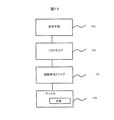
また、広告内容は図13に示したように、ディスク104に記録され、記録再生ドライブ103及びソフトウエア102を介して表示手段101に表示させる方法だけでなく、図14に示したようにディスク108には広告内容のリンク先情報を記録しておき、リンクされた広告はソフトウエア106記に存在し、記録再生ドライブ107及びを介して表示手段105に表示させる方法でもよい。
【0063】
さらに、図15のようにディスク112には広告内容のリンク先情報を記録しておき、リンクされた広告はソフトウエア110を介して外部情報配信手段113より広告情報を入手し、表示手段109に表示させてもよい。広告内容のリンク先情報はディスク112より、記録再生ドライブ111を用いて再生する。
【0064】
広告内容のリンク先情報をディスクに記録しておき、外部情報配信手段と接続することにより、広告内容を更新することが出来る。外部情報配信手段とは、双方向テレビ、インターネット、等情報のやりとりができる手段である。
【0065】
また、ユーザデータをディスク/ソフト上に記録しておき、この内容に併せて広告表示する内容を選択できるようにすると広告効果が高まる。ユーザが記録処理を行なった時間、記録量、記録内容(動画、静止画、データ、音声)、記録回数、ユーザの使用環境等に併せて変えてもよい。
【0066】
本実施例に記載されていない事項については、実施例1〜4と同様である。
【0067】
また,上記実施例では従来の光ディスクとしてDVD−RAMを取り上げたが,これに関しても,基本的には,記録領域を有すれば、ROMと混在でもよく、書き換え型すべての媒体に関して適用可能な技術である
【0068】
【発明の効果】
以上のように本発明を用いることにより,ハードウェアや物理仕様の変更なしに,容易に記録保護機能などの拡張機能が実現でき,かつ,拡張機能の存在を認識しない従来装置で誤記録されたり、情報が破壊されたりする心配の無い,安全な光記録システムを提供できる。
【図面の簡単な説明】
【図1】本発明の目的と効果を示す概念図。
【図2】光記録再生装置の一例のブロック図。
【図3】光記録再生装置の一例のブロック図。
【図4】本発明の情報記録媒体の論理フォーマットの例を示す図。
【図5】本発明の目的と効果を示す概念図。
【図6】アドレス情報の配置の仕方を示す図。
【図7】本発明の目的と効果を示す概念図。
【図8】アドレス情報の配置の仕方を示す図。
【図9】光記録再生装置での動作を説明する流れ図。
【図10】本発明の動作原理を説明する流れ図。
【図11】本発明の一実施例(応用例)の概念説明図。
【図12】本発明の一実施例における動作原理を説明する流れ図。
【図13】本発明の一実施例における広告記録位置説明図。
【図14】本発明の一実施例における広告記録位置説明図。
【図15】本発明の一実施例における広告記録位置説明図。
【図16】本発明の一実施例における動作原理を説明する流れ図。
【符号の説明】
11…光ディスク,2…光ヘッド,21…光スポット,22…光ビーム,23…対物レンズ,24…コリメタ−レンズ,25…レーザ,26…検出器,27…検出器,28…ビームスプリッタ,29…ホログラム素子,31…レンズアクチュエータ,41…信号再生ブロック。[0001]
BACKGROUND OF THE INVENTION
The present invention relates to an arrangement of recording data of a medium for recording information, and more particularly to a system for recording with a recording / reproducing drive that is generally distributed.
[0002]
[Prior art]
As an example of the information recording system, an example of an information recording medium system having target information (for example, advertisement) in a conventional optical recording system will be described with reference to FIGS.
[0003]
FIG. 3 shows a block diagram of a conventional optical recording / reproducing apparatus. Light emitted from a laser light source 25 (wavelength of about 660 nm in DVD-RAM) that is a part of the head 2 is collimated into a substantially
[0004]
When the instruction from the host device to the optical recording / reproducing device is recording, the microprocessor receives the recording data from the host device and stores it in the memory, and controls the automatic position control means to control the
[0005]
As shown in FIG. 6, the address signal is arranged for each information recording unit area, and is arranged at the head of the recording unit area. The position can be confirmed.
[0006]
FIG. 9 shows an example of the flow of operation of an optical recording system that drives a DVD-RAM disc defined in the international standard ISO / IEC-16824, which is a rewritable DVD, as an example of the optical recording system described above. It is.
[0007]
When a disc is inserted or the optical recording system is turned on, the optical recording system first performs processing for determining the type of medium. Usually, in addition to a DVD-RAM medium, it has a reproduction function of a CD-ROM or DVD-ROM which is a reproduction-only medium. For this reason, the optical recording system first performs a medium type determination process to determine which of the above media is used. This method of discrimination processing varies depending on each system. For example, in some systems, the type of medium is discriminated from analog characteristics of a reproduction signal such as reflectivity and focus error signal. In other cases, a medium physical information holding area provided on a disk substrate is reproduced and its contents (data) are used for the medium. Some of them determine the type of the.
[0008]
When the optical recording system recognizes that the type of the medium is a rewritable type, that is, a DVD-RAM, first, the recording content such as the defect management information area is inspected to determine whether or not the optical disc has been physically formatted. If it is not physically formatted, it waits until a physical format instruction is received from an upper device or a user.
[0009]
If the optical disc has been physically formatted, the optical recording system waits for instructions from the user or the host device after performing recording preparation processing such as calibration processing and logical consistency verification. When any command is received, the optical recording system checks the type of command, and if it is a recording command, performs the recording process. In the case of commands such as playback, formatting, and disk ejection, corresponding processing is performed. Normally, these processes end normally, but in the unlikely event that recording fails for an unpredictable reason, error processing such as retry or replacement processing is performed.
[0010]
In the case of a normal DVD-RAM, during this recording process, whether or not the recording data has been normally recorded is actually reproduced and confirmed, and if necessary, a replacement process using another recording unit area is performed. , The reliability of recorded data is increased. The management information related to the reallocation of the recording area by the replacement process is recorded in a special area (defect management area) on the recording medium.
[0011]
[Problems to be solved by the invention]
In the above-described conventional example, in the existing optical recording system, in the information recording medium on which the target information is recorded, the recorded data can basically be freely erased and rewritten. Since the target information may be erased or rewritten before the target information is displayed, there is a problem that the display effect of the target information is low.
[0012]
An object of the present invention is to provide an information recording medium and an optical recording system that display target information without changing hardware or physical specifications.
[0013]
[Means for Solving the Problems]
The above object is achieved by the following configuration.
[0014]
First, an area where recording is restricted is created on the recording medium. Then, when a recording command is given to this recording medium, or when the recording medium is set in the recording device, a command for displaying target information such as an advertisement is issued. Display on the screen or TV screen. After that, by releasing the restriction on the area where the recording is restricted, the recording can be performed. Then, recording is actually performed.
[0015]
Thereby, a new usage of the medium can be obtained. For example, when the target information is based on an advertisement from a company, the company pays a predetermined amount to the recording medium manufacturer on condition that the advertisement is displayed by the company using the medium. When the recording medium manufacturer sells the recording medium, the recording medium manufacturer receives payment from the company that is the advertiser. Therefore, the recording medium can be sold at a lower cost. Therefore, the user of the recording medium can purchase the recording medium at a low cost.
[0016]
The creation of the area in which the recording is restricted is performed by making the arrangement information of the restricted area unreadable. The restriction is released by recording the restricted area arrangement information on a recording medium. Since recording cannot be performed without the arrangement information of the recording restriction area, recording cannot be performed on the recording medium at this stage. On the other hand, by using dedicated control software, it is canceled that the arrangement information of the restricted area is not readable, and can be read. Here, by recording the limited area arrangement information on the recording medium, the second and subsequent recordings can be performed without the above-described dedicated control software.
[0017]
In addition, when it is desired to continue to use the dedicated control software, the arrangement information of the limited area is recorded on the software. In this way, control software is required for the second and subsequent recordings, and the use of the software can be forced.
[0018]
Here, the area where the recording is restricted is created as follows. In the DVD-RAM, as shown in FIG. 6, a physical ID (address information) is arranged in the form of embossed pits at the beginning of each recording sector. Address information for identifying one sector is recorded in quadruple to ensure reliability. Here, the recording apparatus determines that the address is normal if it can reproduce normally any one of the quadruple address information. Therefore, in order to make recording impossible, all four pieces of address information are prevented from being reproduced normally. As a specific example of a method for preventing this address from being reproduced normally, as shown in FIG. 8, the address information is composed of a sector attribute, an address number, and an IED, but ID error detection added to each address information is detected. For example, the code (IED) and the corresponding ID may be inconsistent.
[0019]
On the other hand, as a process of releasing the restriction, a dedicated control software is used to perform a defect sector jump process or a replacement process based on the record restriction area arrangement information in the information recording medium, and a defect management table. Process to rewrite. Here, as described above, when the ID error detection code (IED) added to each address information is inconsistent with the corresponding ID, specifically, the originally matched IED is used. 1 plus 1 was used. In order to make this inconsistency consistent, the control software can subtract 1 from the IED to obtain the original consistent IED, thereby releasing the restriction that made recording impossible.
[0020]
This dedicated control software issues a command to display target information (for example, advertisement), and then releases the restriction that made recording impossible. Actually, after the recording command, a command to display the target information (for example, advertisement) is issued, and defective sector jump processing or replacement is performed based on the recording restriction area arrangement information in the information recording medium and / or software. The process is performed, and the defect management table rewrite process is performed.
[0021]
The flow after the recording command is shown in FIGS. FIG. 16 shows the processing when the target information and the recording restriction area arrangement information, or the recording destination of the information is recorded on the software. When a recording command is issued, a recording restriction area determination process is performed, and when the area information recorded on the software is found, the process proceeds to Yes, and after a display instruction for the target information is issued, Recording is possible. If No, or until an information display command is issued, the disc is processed as a read-only disc. Processing up to this point is performed on software, and thereafter processing is performed on the recording means. After recording becomes possible, it is confirmed that the recording process is normally performed. When recording is not possible, such as when there is no recording data, it is processed as a read-only disc. If recording is not performed normally, it is processed as an error.
[0022]
FIG. 12 shows a process in the case where the target information and the recording restriction area arrangement information, or the recording destination of these information is recorded on the recording means or the medium.
[0023]
When a recording command is issued, a recording restriction area determination process is performed, and when the area information recorded on the software is found, the process proceeds to Yes, and after a display instruction for the target information is issued, Recording is possible. If No, or until an information display command is issued, the disc is processed as a read-only disc. After the recording command is issued, information display processing is performed on software, and other points are processed on recording means. After recording becomes possible, it is confirmed that the recording process is normally performed. When recording is not possible, such as when there is no recording data, it is processed as a read-only disc. If recording is not performed normally, it is processed as an error.
[0024]
It is also possible to repeat a plurality of times by issuing a command to display the target information and then releasing the restriction. In such a case, for example, an advertisement is displayed every time a user tries to record.
[0025]
Here, the target information may be recorded on a recording medium. This has the advantage of facilitating information distribution. On the other hand, the target information may be recorded in dedicated software. Thereby, it is not necessary to occupy the recording area on the medium, and there is an advantage that the recording capacity of the medium is large. Furthermore, the target information may be reproduced via external information distribution means. For example, an advertisement or the like is displayed on the screen of a personal computer via the Internet. According to this, the storage capacity of the medium is not occupied by the intended information, and the capacity of the dedicated software is reduced.
[0026]
In addition, when a recording command is issued, a signal for issuing a command for displaying target information (such as an advertisement) and a signal for releasing the recording restriction may be provided on the information recording medium itself. In this case, the above-described dedicated software is on the information recording medium, and installation of the dedicated software into the system is unnecessary / simplified.
[0027]
The target information and the arrangement information of the restricted area may be recorded in the same place. Note that recording in the same place means recording the information in a form that cannot be separated by combining them. Here, since the target information and the arrangement information of the restricted area are recorded at the same position, if the target information is deleted, at least a part of the arrangement information of the restricted area is deleted. As a result, information recorded on the recording medium cannot be reproduced. As an example of use, if the target information is an advertisement, an advertisement is always displayed for recording, so that a recording medium with a high advertisement audience rate can be realized.
[0028]
DETAILED DESCRIPTION OF THE INVENTION
(Example 1)
FIG. 3 shows an example of a block diagram of a DVD-RAM recording / reproducing apparatus which is an optical information recording apparatus. First, the operation when a recording-free medium is loaded in this apparatus will be described.
[0029]
Light emitted from a laser light source 25 (wavelength of about 660 nm in DVD-RAM) that is a part of the head 2 is collimated into a substantially
[0030]
However, in an external recording device connected to a host device such as a PC like this device, the processing in the host device becomes complicated if the start address of the recording area is different for each device type. Access from the device is performed using a logical block address (LBA). Here, the logical block address refers to a code that logically represents an address number, not a physical position on the recording medium.
[0031]
In the apparatus of this embodiment, the conversion between the LBA and the PSN is performed by the microprocessor in the apparatus, but an address conversion circuit may be used as in the example of FIG. The microprocessor discriminates the type of the loaded medium (see FIGS. 9 and 10). If the medium is a DVD-RAM, the outside of the data area (two locations on the inner and outer sides) The defect management table (PDL and SDL) reserved in the defect management area (DMA) is read, and the defective sector jump process and replacement process are performed to associate the PSN and the LBA (FIG. 4). In a DVD-RAM disk having a diameter of 120 mm and a single-side capacity of 4.7 GB, the rewrite data area is located from the innermost PSN = 31000h to the outermost PSN = 265F5Fh. Of these, an area from 31000h to 341FFh is reserved as a basic spare area (PSA) for replacement of defective sectors. Here, the basic spare area is an area used for replacement when a defective sector occurs. This PSA includes 12800 (3200h) spare sectors. In DVD-RAM, in addition to PSA, an additional spare area (SSA) can be secured on the outermost periphery. In this example, an SSA of 49152 sectors from PSN = 259F60 to PSN = 265F5F is secured on the outermost periphery. As a result, the user area is from PSN = 34200h to PSN = 259F5Fh. In this period, 2252128 sectors are included, but since the DVD-RAM disc has a zone CLV configuration, 2245920 excluding the guard area at the zone boundary is a user sector. Therefore, LBAs from LBA = 0 (PSN = 34200h) to LBA = 2245919 (PSN = 259F5Fh) are associated with the user sector.
[0032]
There are two types of defect management tables, PDL (primary defect management table) and SDL (secondary defect management table). The PDL is used to register initial defects found at the time of media shipment or media certification. The PSN of the defective sector is recorded in the PDL, and the recording / reproducing apparatus does not allocate the LBA to the sector having the PSN listed in the PDL (Slipping). The recording / reproducing apparatus allocates the LBA so that the user data area advances into the PSA by the amount of the slipped sector. That is, the head of the user area shifts in a direction where PSN is smaller (inner circumference side) than PSN = 34200h. About 8000 defective sector information can be registered in the PDL. If there is a defect that is not listed in the defect management table, a defect sector jump process or a replacement process is performed to rewrite the defect management table. If these processes are not performed, the sector and the succeeding sector become a recording error and cannot be recorded.
[0033]
Therefore, in this embodiment, the following recording medium and dedicated software are used so that a recording-restricted medium can be used without problems in the conventional system.
[0034]
First, a plurality of recording blocks including the head part (4096 sectors) of the user area are set as a recording restriction area (see FIG. 4). The recording restriction area is realized for the inconsistency between the address number as the address data and the ID error detection data (IED) (see FIG. 8). In the dedicated software, when a recording command is given to an information recording medium having a recording restriction area, a command to display the target information (such as an advertisement) is issued, and then the recording restriction is released. Recording was performed in the restricted area. The target information and the recording restriction area arrangement information are recorded at the same location in the information recording medium. Recording in the same place means recording in a form that cannot be separated by combining both information. Further, as a step of releasing the restriction, a defect sector jump process or a replacement process is performed based on the record restriction area arrangement information in the information recording medium, and a defect management table is rewritten.
[0035]
Hereinafter, the operation principle of this embodiment will be described. In this embodiment, there is a recording restriction area. However, since the recording restriction area does not exist in the logical user area (logical volume space) that is the user recording area after logical formatting, there is no problem in normal use. Here, the recording restricted area refers to an area recognized as a defective sector. In the UDF format, the placement position is determined only for AVDP (Anchor Volume Descriptor Pointer), and the defect management table is recorded in two or more locations of LBA = 256, LBA = 512, LBA = N-256 (where N is the final LBA). It is supposed to be. In the 4.7 GB DVD-RAM which is the case of this embodiment, AVDP is recorded at two locations, LBA = 256 and LBA = 2294815. In the AVDP, the arrangement positions of two main and spare logical volume recognition sequences (VRS) are described. In this embodiment, the VRS is arranged in 16 sectors from LBA = 4096 and 16 sectors from LBA = 4112. In subsequent sectors, LVIDs (logical volume integrity descriptors) are arranged, and the logical volume space is arranged so as to start with LBA = 4352, and end with LBA = 2290975. That is, the user capacity (logical volume space) on the logical format is about 4.68 gigabytes. In the logical volume space, a space bitmap, a file set descriptor, a directory, a user file, and the like are arranged. Here, the UDF format is an abbreviation for Universal Disk Format, which is a comprehensive format for magneto-optical disks. This format has the feature that long file names can be used as file names, regardless of the media or OS. Similarly, in cases other than the UDF format, there is a recording restriction area on the physical format, but by recording the recording restriction area in the defect management table, the recording restriction area is a user recording area on the logical format. Since it does not exist in the logical user area (logical volume space), there is no problem in normal use. In addition, although the example which used UDF for random recording was shown as a file system (logical format), the file system for write-once or sequential recording can be used especially when there is a strong restriction in rewriting. It is.
[0036]
Therefore, if the target information is displayed and the recording restricted area information is recorded along with the display, the medium of the present invention can be recorded without any problem by a conventional recording / reproducing apparatus or file system.
[0037]
When the recording restriction area arrangement information is recorded in the user area of the medium, the medium can then be recorded by a conventional recording / reproducing apparatus having no dedicated software. On the other hand, when the recording restriction area arrangement information is recorded not in the medium but in the file system in the dedicated software, the medium can be recorded only by a recording / reproducing apparatus having the dedicated software thereafter. Event information such as the number of times of recording, that is, the number of times of display of the target information is recorded together with the recording limit area arrangement information, and can be used to limit the number of times of recording and display the target information according to the number of times of recording if it is referenced during the next recording. I can do it.
[0038]
Next, a description will be given of a case where target information (such as an advertisement) in the medium of the present embodiment is deleted by mistake. There is a possibility that the target information may be erased. However, since the recording restriction area arrangement information is recorded together with the target information, the recording restriction area arrangement information is also erased together. It becomes impossible. Therefore, the medium of this embodiment cannot be recorded without displaying the target information.
[0039]
Thus, when the user records, the target information can always be displayed, and therefore the display efficiency of the target information is very high.
[0040]
FIG. 10 shows an example of the operation flow of an optical recording system for driving a DVD-RAM disc defined in the international standard ISO / IEC-16824, which is a rewritable DVD, as an example of the optical recording system of the present invention. Is.
[0041]
When a disc is inserted or the optical recording system is turned on, the optical recording system first performs processing for determining the type of medium. Usually, in addition to a DVD-RAM medium, it has a reproduction function of a CD-ROM or DVD-ROM which is a reproduction-only medium. For this reason, the optical recording system first performs a medium type determination process to determine which of the above media is used. This method of discrimination processing varies depending on each system. For example, in some systems, the type of medium is discriminated from the analog characteristics of a reproduction signal such as reflectance and focus error signal. Some of them determine the type of the.
[0042]
When the optical recording system recognizes that the type of the medium is a rewritable type, that is, a DVD-RAM, first, the recording content such as the defect management information area is inspected to determine whether or not the optical disc has been physically formatted. If the arrangement information of the recording restriction area is recorded in the system (medium defect management information area, software, hardware) or the recording destination of the arrangement information is recorded, it is determined that recording is possible. In the present invention, since the arrangement information of the recording restriction area is recorded in the system together with the information display function, it is determined that recording is possible.
[0043]
If it is not physically formatted, it waits until a physical format instruction is received from an upper device or a user. If the optical disc has been physically formatted, the optical recording system waits for instructions from the user or the host device after performing recording preparation processing such as calibration processing and logical consistency verification. When any command is received, the optical recording system checks the type of the command, and if it is a recording command, the target information display command is activated, and recording processing is performed after an information display instruction is given.
[0044]
The start of the information display operation is before recording, but the timing at which information is displayed may be during recording, or may be before recording or after recording.
[0045]
In the case of commands such as playback, formatting, and disk ejection, corresponding processing is performed. Normally, these processes end normally, but in the unlikely event that recording fails for an unpredictable reason, error processing such as retry or replacement processing is performed.
[0046]
Such a dedicated information recording medium and a system using the dedicated information recording medium are rewritable storage media capable of erasing and re-recording user data with respect to target information, for example, a user data area in which an advertisement is recorded. However, it has a function of not deleting or re-recording the target information, for example, until an advertisement is displayed.
[0047]
This makes it impossible to delete or rewrite the target information, for example, before the advertisement is displayed, and to display the target information (for example, the advertisement) compared to the conventional optical recording system. It was extremely expensive.
[0048]
The flow after the recording command is shown in FIGS. FIG. 16 shows the processing when the target information and the recording restriction area arrangement information, or the recording destination of the information is recorded on the software. When a recording command is issued, a recording restriction area determination process is performed, and when the area information recorded on the software is found, the process proceeds to Yes, and after a display instruction for the target information is issued, Recording is possible. If No, or until an information display command is issued, the disc is processed as a read-only disc. Processing up to this point is performed on software, and thereafter processing is performed on the recording means. After recording becomes possible, it is confirmed that the recording process is normally performed. When recording is not possible, such as when there is no recording data, it is processed as a read-only disc. If recording is not performed normally, it is processed as an error.
[0049]
FIG. 12 shows a process in the case where the target information and the recording restriction area arrangement information, or the recording destination of these information is recorded on the recording means or the medium.
[0050]
When a recording command is issued, a recording restriction area determination process is performed, and when the area information recorded on the software is found, the process proceeds to Yes, and after a display instruction for the target information is issued, Recording is possible. If No, or until an information display command is issued, the disc is processed as a read-only disc. After the recording command is issued, information display processing is performed on software, and other points are processed on recording means. After recording becomes possible, it is confirmed that the recording process is normally performed. When recording is not possible, such as when there is no recording data, it is processed as a read-only disc. If recording is not performed normally, it is processed as an error.
(Example 2)
An example of a method for forming a recording restriction area will be described. In the DVD-RAM, as shown in FIG. 6, a physical ID (address information) is arranged in the form of an emboss pit at the head of each recording sector. Address information for identifying one sector is recorded in quadruple to ensure reliability.
[0051]
The recording / reproducing device determines that the address is normal if it can normally reproduce any one of the quadruple address information. Therefore, in order to make recording impossible, all four address information must not be reproduced normally. Keep it. As a method for preventing this address from being reproduced normally, the ID corresponding to the ID error detection code (IED) added to each address information is inconsistent as shown in FIG. Specifically, a value obtained by adding 1 to the originally matched IED was used. As described above, the method of making the ID data itself inconsistent can be applied at the time of mastering the medium, and is automatically applied to all the media at the same time as the substrate is formed. It is. In this embodiment, at least the first two sectors and the last three sectors in one track can be reproduced instead of making all the IDs of the recording restricted area unreproducible. More specifically, in the inner periphery, the first 2 sectors can be reproduced, the next 8 sectors cannot be reproduced, the next 4 sectors can be reproduced, the next 8 sectors cannot be reproduced, and the last 3 sectors can be reproduced. When applied to the outer periphery, the first 2 sectors can be reproduced, the next 10 sectors cannot be reproduced, the next 5 sectors can be reproduced, the next 10 sectors cannot be reproduced, the 4 sectors can be reproduced, the 10 sectors can be reproduced, the 5 sectors can be reproduced, 10 Sector playback is not possible, and the last 3 sectors can be played back. As described above, since a part of addresses in the track can be reproduced, access is not hindered. In this example, since the sectors near the head and the end of the track can be reproduced, the ID information of the land / groove switching portion can be reliably reproduced, so that the stability of the servo is ensured. Further, eight or more sectors that cannot be reproduced by ID are continuously arranged. Thus, at least 8 sector IDs in one ECC block (error correction code block) cannot be reproduced. In addition, at least six of the sectors are configured such that sectors that cannot be reproduced are continuous. Depending on the recording / reproducing apparatus, there is a system that is configured to automatically interpolate and record even if there is a sector that cannot be reproduced during recording. However, even in a system having such an interpolation function, ID reproduction is possible. It is possible to ensure that a recording error occurs when a sector that cannot be recorded continues several sectors or more. That is, the recording restricted area can be intentionally formed.
[0052]
In addition, in order to make some sectors of the ID of the recording restricted area unreproducible, the reflectance is lowered by a method of making the ID part of the unreproducible part amorphous, etc. You may process after formation. Alternatively, the initialization process may be such that only the ID part of the unreproducible part is masked / the laser power is modulated so that the initialization is not performed. Although these methods are expensive, there is an advantage that the recording restriction area can be easily changed individually. Further, for example, a pit or the like may be provided in a part of the recording track, or the recording film may be altered by strong laser light or the like.
(Example 3)
In this embodiment, the recording restriction area is distributed over the entire user area, and information regarding the existence position and target information are recorded as encrypted data on the disk as disk manufacturer information. In this embodiment, an example of a dedicated device driver is shown. The dedicated device driver has a function of reading the encrypted data from the medium and registering it as an invisible file so that the recording restricted area does not enter the user area, or performing recording and reproduction by performing address conversion. In the case where there are recording restricted areas in various parts of the user area as in the present embodiment, reproduction cannot be performed by a conventional device driver, so dedicated software is required. By utilizing this fact, it is possible to construct an application system such as the fifth embodiment described below.
[0053]
Data encryption was as follows. In the system of this embodiment corresponding to encryption, one key is given from a large number of master key sets including 400 or more, and is recorded in dedicated software. The disc key is recorded as a set with the arrangement information of the recording restriction area. As a result, by removing the key from the disc, the arrangement information of the recording restriction area is erased and recording becomes impossible. The decryption algorithm consists of exchanging system keys and encryption keys. At that time, the exchange of the disc key and the title key necessary for decoding the arrangement information and the like from the disc is not clear to the user. This system has a circuit for decoding the arrangement information of the recording restriction area after instructing the information display. An encryption method other than the above may be used.
[0054]
In the second embodiment, an example in which a random recording UDF is used as the file system (logical format) has been shown. However, when there is a strong restriction on rewriting, a file system for write-once or sequential recording is used. It is also possible to use. In this case, for example, it is preferable to use encryption so as to operate only with a specific device driver as in this embodiment.
Example 4
The concept of the optical recording system of the present invention will be described with reference to FIGS. The invention described in the present embodiment is a system in which the recording restriction is released if the target information (for example, advertisement) is viewed once, and recording is possible even in the conventional system. This is realized by recording the recording restriction area arrangement information described in detail in the first embodiment on an information recording medium.
[0055]
As a medium, a conventional recording / reproducing apparatus can be used for recording and reproduction using standard control software (for example, a device driver attached to the OS).
[0056]
On the other hand, with respect to the recording restriction function system having target information, a standard apparatus and dedicated control software as described in the first and fifth embodiments are used in combination. FIG. 1 shows a state before viewing target information (for example, advertisement), and a medium with recording restriction / purpose information (for example, advertisement) can be reproduced by a conventional system, but cannot be recorded. FIG. 1 shows a viewing version only for the first recording. In the system with a recording restriction function, after the target information (for example, advertisement) viewing command is issued, the recording restriction is released and recording is possible.
[0057]
FIG. 5 shows a state after viewing the objective information (for example, advertisement) from the state of FIG. Note that FIG. 5 also shows the viewing version only at the time of the first recording. As described above, in the medium of the present embodiment, the recording restriction is released, and recording can be performed in this system and the conventional system.
[0058]
However, if part or all of information such as a description location of the purpose information (for example, advertisement) / purpose information (for example, advertisement) is deleted without viewing the purpose information (for example, advertisement), the state shown in FIG. It becomes. FIG. 7 also shows the viewing version only at the time of the first recording. This is because part / all of the recording restriction area arrangement information recorded together with part / all of the information such as the description location of the purpose information (for example, advertisement) / purpose information (for example, advertisement) is deleted. This is because the restriction cannot be removed. Thus, in order to record on the information recording medium of the present invention, viewing of the target information (for example, an advertisement) is always required.
[0059]
In any case, the present invention is characterized in that a recording-restricted medium having target information can be recorded by a conventional apparatus (standard apparatus) after a viewing instruction for the target information (for example, advertisement). It is.
(Example 5)
FIG. 11 shows an advertisement display system using the information record of the present invention. In this case, the target information is an advertisement.
[0060]
The recording method of the recording / reproducing restricted medium is as described in the first and second embodiments.
[0061]
When this system is used, since the user has an advertisement, the user purchases an information recording medium at a lower price / free of charge. In order to record this medium using a general drive, dedicated software is required, and an advertisement is displayed during recording. That is, since the advertiser pays the advertising fee to the media manufacturer / software manufacturer, the media manufacturer / software manufacturer can sell the information recording medium at a low price. The display here means that the user can watch / experience the advertisement, such as listening to sound, feeling vibration, touching, sniffing, feeling the atmosphere, etc. in addition to viewing.
By using this system, it was possible to construct a business model in which those prices were distributed as consideration for the object / work as indicated by the arrows in FIG. The advantage of this business model is that it can use ordinary drives, so there are a large number of target audiences, and because it can be viewed / experienced with advertisements reliably, the advertising effectiveness is also high in terms of number and quality. is there.
[0062]
Further, the advertisement content is recorded on the
[0063]
Further, as shown in FIG. 15, the link information of the advertisement contents is recorded on the
[0064]
The advertisement contents can be updated by recording the link information of the advertisement contents on a disk and connecting to external information distribution means. The external information distribution means is a means capable of exchanging information such as interactive television and the Internet.
[0065]
In addition, if user data is recorded on a disc / software, and the content to be displayed as an advertisement can be selected along with this content, the advertising effect is enhanced. The time when the user performs the recording process, the recording amount, the recording content (moving image, still image, data, sound), the number of times of recording, the usage environment of the user, and the like may be changed.
[0066]
Matters not described in the present embodiment are the same as those in the first to fourth embodiments.
[0067]
In the above embodiments, the DVD-RAM is taken up as a conventional optical disk. In this regard, basically, a technology that can be applied to all rewritable media may be mixed with ROM as long as it has a recording area. Is
[0068]
【The invention's effect】
As described above, by using the present invention, it is possible to easily realize an extended function such as a recording protection function without changing hardware or physical specifications, and erroneous recording may occur in a conventional apparatus that does not recognize the existence of the extended function. It is possible to provide a safe optical recording system without worrying about information being destroyed.
[Brief description of the drawings]
FIG. 1 is a conceptual diagram showing the objects and effects of the present invention.
FIG. 2 is a block diagram of an example of an optical recording / reproducing apparatus.
FIG. 3 is a block diagram illustrating an example of an optical recording / reproducing apparatus.
FIG. 4 is a diagram showing an example of a logical format of the information recording medium of the present invention.
FIG. 5 is a conceptual diagram showing the objects and effects of the present invention.
FIG. 6 is a diagram showing a method of arranging address information.
FIG. 7 is a conceptual diagram showing the objects and effects of the present invention.
FIG. 8 is a diagram showing a method of arranging address information.
FIG. 9 is a flowchart for explaining the operation of the optical recording / reproducing apparatus.
FIG. 10 is a flowchart illustrating the operation principle of the present invention.
FIG. 11 is a conceptual explanatory diagram of one embodiment (application example) of the present invention.
FIG. 12 is a flowchart illustrating the operation principle in one embodiment of the present invention.
FIG. 13 is an explanatory diagram of an advertisement recording position in an embodiment of the present invention.
FIG. 14 is an explanatory diagram of an advertisement recording position in one embodiment of the present invention.
FIG. 15 is an explanatory diagram of an advertisement recording position in an embodiment of the present invention.
FIG. 16 is a flowchart for explaining the operating principle in one embodiment of the present invention.
[Explanation of symbols]
DESCRIPTION OF
Claims (16)
前記記録制限領域に、予め記録された情報を再生することで、前記記録制限が解除された前記記録制限領域に、新たな情報の記録を行う工程とを有することを特徴とする記録方法。A step of releasing the recording restriction of the recording restriction area and recording information in the recording restriction area for a recording medium having a recording restriction area in which recording of information is temporarily restricted; ,
And recording the new information in the recording restriction area where the recording restriction is released by reproducing information recorded in advance in the recording restriction area.
前記制限を解除する工程は、前記領域の配置情報を前記媒体に記録する工程であることを特徴とする請求項1記載の記録方法。The recording restriction is performed by making the arrangement information of the recording restriction area unreadable,
The recording method according to claim 1, wherein the step of releasing the restriction is a step of recording arrangement information of the area on the medium.
前記制限を解除する工程は、前記領域の配置情報をソフトウエア上に記録する工程であることを特徴とする請求項1記載の記録方法。The recording restriction is performed by making the arrangement information of the recording restriction area unreadable,
The recording method according to claim 1, wherein the step of releasing the restriction is a step of recording arrangement information of the area on software.
前記記録命令がなされた際に、所定の情報の表示の命令を出す工程を有することを特徴とする請求項1乃至3何れかに記載の記録方法。A step of issuing a recording command to the recording medium before releasing the recording restriction;
4. The recording method according to claim 1, further comprising a step of issuing a command for displaying predetermined information when the recording command is issued.
前記解除は、前記不整合とされた前記IDエラー検出符号と前記IDとを整合させるようにすることであることを特徴とする請求項1乃至8何れかに記載の記録方法。The recording restriction restricts recording by making the ID error detection code of the address information in the recording restriction area inconsistent with the ID corresponding to the ID error detection code,
9. The recording method according to claim 1, wherein the canceling is performed by matching the ID error detection code determined to be inconsistent with the ID.
前記情報の消去動作により、前記配置情報も消去されることを特徴とする請求項1記載の記録方法。The recording restriction is performed by making the arrangement information of the recording restriction area unreadable,
The recording method according to claim 1, wherein the arrangement information is also erased by the information erasing operation.
前記記録制限領域に予め記録された情報を再生して、前記記録制限を解除し、
所定のソフトウエアを用いて、前記暗号化された位置情報を解読して、前記記録制限が解除された領域に新たな情報を記録することを特徴とする情報の記録方法。Temporarily has a recording restriction area is limited to recording information, the recording medium in which information relating to the position information of the recording-limited area is recorded is encrypted,
Play back information recorded in advance in the recording restriction area, release the recording restriction,
Using predetermined software decrypts the encrypted position information, the recording method of the information and recording the new information on the recording limit is canceled area.
Priority Applications (3)
| Application Number | Priority Date | Filing Date | Title |
|---|---|---|---|
| JP2001314720A JP3925144B2 (en) | 2001-10-12 | 2001-10-12 | Recording method and recording medium |
| US10/084,379 US7584150B2 (en) | 2001-10-12 | 2002-02-28 | Recording method, recording medium, and recording system |
| US12/506,751 US20090285071A1 (en) | 2001-10-12 | 2009-07-21 | Recording method, recording medium, and recording system |
Applications Claiming Priority (1)
| Application Number | Priority Date | Filing Date | Title |
|---|---|---|---|
| JP2001314720A JP3925144B2 (en) | 2001-10-12 | 2001-10-12 | Recording method and recording medium |
Publications (3)
| Publication Number | Publication Date |
|---|---|
| JP2003123384A JP2003123384A (en) | 2003-04-25 |
| JP2003123384A5 JP2003123384A5 (en) | 2005-02-24 |
| JP3925144B2 true JP3925144B2 (en) | 2007-06-06 |
Family
ID=19132985
Family Applications (1)
| Application Number | Title | Priority Date | Filing Date |
|---|---|---|---|
| JP2001314720A Expired - Lifetime JP3925144B2 (en) | 2001-10-12 | 2001-10-12 | Recording method and recording medium |
Country Status (2)
| Country | Link |
|---|---|
| US (2) | US7584150B2 (en) |
| JP (1) | JP3925144B2 (en) |
Families Citing this family (51)
| Publication number | Priority date | Publication date | Assignee | Title |
|---|---|---|---|---|
| KR100716965B1 (en) * | 2002-08-17 | 2007-05-10 | 삼성전자주식회사 | Optical information storage medium and recording method of the same |
| CN100474403C (en) | 2002-09-26 | 2009-04-01 | Lg电子株式会社 | Method for managing defective area on write-once optical recording medium |
| BRPI0306564B1 (en) * | 2002-09-26 | 2016-04-26 | Lg Electronics Inc | method of recording optical media management having at least one defective area in the user data area, recording media and recording optical media management apparatus having at least one temporary defect management area and a spare area in the data area |
| KR20040027259A (en) * | 2002-09-26 | 2004-04-01 | 엘지전자 주식회사 | Method for managing a defect area on optical disc write once |
| US7233550B2 (en) | 2002-09-30 | 2007-06-19 | Lg Electronics Inc. | Write-once optical disc, and method and apparatus for recording management information on write-once optical disc |
| KR20040028469A (en) * | 2002-09-30 | 2004-04-03 | 엘지전자 주식회사 | Method for managing a defect area on optical disc write once |
| KR101036473B1 (en) * | 2002-12-11 | 2011-05-24 | 엘지전자 주식회사 | Method of managing overwrite and method of recording management inforamtion on an optical disc write once |
| US7372788B2 (en) * | 2003-01-14 | 2008-05-13 | Lg Electronics Inc. | Method for managing defective area on write-once optical recording medium, and optical recording medium using the same |
| TWI314315B (en) * | 2003-01-27 | 2009-09-01 | Lg Electronics Inc | Optical disc of write once type, method, and apparatus for managing defect information on the optical disc |
| US7672204B2 (en) * | 2003-01-27 | 2010-03-02 | Lg Electronics Inc. | Optical disc, method and apparatus for managing a defective area on an optical disc |
| US20040160799A1 (en) * | 2003-02-17 | 2004-08-19 | Park Yong Cheol | Write-once optical disc, and method and apparatus for allocating spare area on write-once optical disc |
| TWI335587B (en) * | 2003-02-21 | 2011-01-01 | Lg Electronics Inc | Write-once optical recording medium and defect management information management method thereof |
| US7499383B2 (en) * | 2003-02-21 | 2009-03-03 | Lg Electronics Inc. | Write-once optical disc and method for managing spare area thereof |
| US7188271B2 (en) * | 2003-02-25 | 2007-03-06 | Lg Electronics Inc. | Write-once optical disc, and method and apparatus for recording management information on write-once optical disc |
| TWI291168B (en) * | 2003-02-25 | 2007-12-11 | Lg Electronics Inc | Defect management method for optical recording medium and optical recording medium using the same |
| TWI278851B (en) * | 2003-02-25 | 2007-04-11 | Lg Electronics Inc | Recording medium having data structure for managing at least a data area of the recording medium and recording and reproducing methods and apparatuses |
| AU2003282449A1 (en) * | 2003-03-04 | 2004-09-28 | Lg Electronics Inc. | Method for recording on optical recording medium and apparatus using the same |
| TWI405196B (en) | 2003-03-13 | 2013-08-11 | Lg Electronics Inc | Optical recording medium and defective area management method and apparatus for write-once recording medium |
| TW200501119A (en) * | 2003-05-09 | 2005-01-01 | Lg Electronics Inc | Recording medium having data structure for managing at least a data area of the recording medium and recording and reproducing methods and apparatuses |
| MXPA05012044A (en) * | 2003-05-09 | 2006-02-03 | Lg Electronics Inc | Write once optical disc, and method and apparatus for recovering disc management information from the write once optical disc. |
| EP1623423A1 (en) * | 2003-05-09 | 2006-02-08 | LG Electronics Inc. | Write once optical disc, and method and apparatus for recovering disc management information from the write once optical disc |
| JP2007528563A (en) * | 2003-05-09 | 2007-10-11 | エルジー エレクトロニクス インコーポレーテッド | Recording medium having data structure for managing at least data area of recording medium, and recording / reproducing method and apparatus |
| EP1647014B1 (en) * | 2003-07-04 | 2012-09-05 | LG Electronics Inc. | Method and apparatus for managing a overwrite recording on a write-once optical disc |
| KR101014703B1 (en) * | 2003-07-15 | 2011-02-21 | 엘지전자 주식회사 | Method and apparatus for managing a defective area on optical disc |
| KR20050009031A (en) * | 2003-07-15 | 2005-01-24 | 엘지전자 주식회사 | Method for recording management information on optical disc write once |
| CN101197167B (en) * | 2003-08-05 | 2011-02-09 | Lg电子株式会社 | Write-once optical disc, and method and apparatus for recording/playback management information on/from optical disc |
| US7313065B2 (en) * | 2003-08-05 | 2007-12-25 | Lg Electronics Inc. | Write-once optical disc, and method and apparatus for recording/reproducing management information on/from optical disc |
| WO2005024793A2 (en) * | 2003-09-08 | 2005-03-17 | Lg Electronics Inc. | Write-once optical disc, and method and apparatus for recording management information thereon |
| JP2007505432A (en) * | 2003-09-08 | 2007-03-08 | エルジー エレクトロニクス インコーポレーテッド | Write-once optical disc, and method and apparatus for recording management information on the optical disc |
| BRPI0414213A (en) * | 2003-09-08 | 2006-10-31 | Lg Electronics Inc | method and apparatus of managing physical recording medium and physical recording medium |
| KR100964685B1 (en) * | 2003-10-20 | 2010-06-21 | 엘지전자 주식회사 | Method and apparatus for recording and reproducing data on/from optical disc write once |
| EP1528554A1 (en) * | 2003-10-31 | 2005-05-04 | Deutsche Thomson-Brandt GmbH | Distinguishing track wobble type during recording and playback of optical recording media |
| KR101024916B1 (en) * | 2004-03-19 | 2011-03-31 | 엘지전자 주식회사 | Method for writing data in high density optical write once disc and Apparatus for the same |
| KR101113866B1 (en) | 2004-03-19 | 2012-03-02 | 엘지전자 주식회사 | Data structure for a recording medium and method and apparatus of recording data on the recording medium |
| KR101049117B1 (en) * | 2004-06-08 | 2011-07-14 | 엘지전자 주식회사 | Method and apparatus for recording management information on optical write once disc |
| KR101014727B1 (en) * | 2004-06-23 | 2011-02-16 | 엘지전자 주식회사 | Method and Apparatus for managing a overwrite in Optical write once disc |
| JP4285344B2 (en) * | 2004-07-08 | 2009-06-24 | ソニー株式会社 | Information recording apparatus and method, program storage medium, and program |
| KR101041811B1 (en) * | 2004-08-02 | 2011-06-17 | 엘지전자 주식회사 | Method and Apparatus for write / reproducing in Optical storage |
| KR101012378B1 (en) * | 2004-08-16 | 2011-02-09 | 엘지전자 주식회사 | Method and Apparatus for recording / reproducing in Optical storage |
| MX2007001243A (en) * | 2004-09-14 | 2007-04-18 | Lg Electronics Inc | Recording medium, and method and apparatus of recording and reproducing data on the same. |
| US7376062B2 (en) * | 2004-10-29 | 2008-05-20 | International Business Machines Corporation | System and method for logical shredding of data stored on worm media |
| KR101229493B1 (en) | 2005-10-26 | 2013-02-04 | 삼성전자주식회사 | Information recording medium, recording/reproducing apparatus and recording/reproducing method for performing effectively write protection |
| KR101227485B1 (en) * | 2005-11-25 | 2013-01-29 | 엘지전자 주식회사 | Recording mdium, Method and Apparatus for recording defect management information on the recording medium |
| KR20070058291A (en) * | 2005-12-02 | 2007-06-08 | 엘지전자 주식회사 | Recording medium, method and apparatus for recording management information on the recording medium |
| JP4695547B2 (en) * | 2006-06-02 | 2011-06-08 | シャープ株式会社 | Recording / reproducing apparatus and recording capacity management method for recording / reproducing apparatus |
| US20100008645A1 (en) * | 2006-08-29 | 2010-01-14 | Pioneer Corporation | Information recording and reproducing device and method, information recording and reproducing system, and computer program |
| US20080181585A1 (en) * | 2007-01-26 | 2008-07-31 | Disney Enterprises, Inc. | System and Method for Allocating Excess Capacity on a Storage Medium |
| US20090048908A1 (en) * | 2007-01-31 | 2009-02-19 | Vulcan Portals, Inc. | Media delivery system |
| US20080183575A1 (en) * | 2007-01-31 | 2008-07-31 | Vulcan Portals, Inc. | Back-channel media delivery system |
| ATE537538T1 (en) * | 2007-03-30 | 2011-12-15 | Pioneer Corp | INFORMATION RECORDING MEDIUM AND ADVERTISING INFORMATION DISTRIBUTION SYSTEM |
| US8700451B2 (en) * | 2008-10-29 | 2014-04-15 | Vulcan Ip Holdings Inc. | Systems and methods for tracking consumers |
Family Cites Families (29)
| Publication number | Priority date | Publication date | Assignee | Title |
|---|---|---|---|---|
| JPH04105269A (en) * | 1990-08-24 | 1992-04-07 | Sony Corp | Disk, disk recorder, and disk reproducing device |
| US5689704A (en) * | 1994-03-04 | 1997-11-18 | Sony Corporation | Recording medium, recording/playback device which uses commands in character string form for audio system control |
| JP3467832B2 (en) * | 1994-04-20 | 2003-11-17 | ソニー株式会社 | Recording method and recording device |
| JPH07326175A (en) * | 1994-05-30 | 1995-12-12 | Sony Corp | Recording/reproducing apparatus |
| JP3519134B2 (en) * | 1994-08-10 | 2004-04-12 | 富士通株式会社 | Software usage measurement device and multimedia information output device |
| JP3557721B2 (en) * | 1995-05-11 | 2004-08-25 | ソニー株式会社 | Recording device |
| JP4023849B2 (en) | 1995-06-30 | 2007-12-19 | ソニー株式会社 | Data recording method and apparatus, and data reproducing method and apparatus |
| DE69729495T2 (en) * | 1996-03-08 | 2004-10-28 | Matsushita Electric Industrial Co., Ltd., Kadoma | Image information processing system and microprocessor for the protected reproduction of audiovisual data |
| JP3476647B2 (en) * | 1996-04-19 | 2003-12-10 | シャープ株式会社 | Optical disk, optical disk manufacturing apparatus and optical disk recording / reproducing apparatus |
| TW384434B (en) * | 1997-03-31 | 2000-03-11 | Sony Corp | Encoding method, device therefor, decoding method, device therefor and recording medium |
| JPH10283451A (en) | 1997-04-10 | 1998-10-23 | Canon Inc | System and device for recording and reproducing information |
| JPH1139804A (en) | 1997-07-14 | 1999-02-12 | Sony Corp | Storage medium |
| TW385436B (en) * | 1997-12-12 | 2000-03-21 | Toshiba Corp | Digital recording system using variable recording rate |
| JPH11213627A (en) * | 1998-01-21 | 1999-08-06 | Toshiba Corp | Recording medium and recording/reproducing apparatus assuring recording or reproducing of recording reserving information |
| JPH11212730A (en) | 1998-01-21 | 1999-08-06 | Matsushita Electric Ind Co Ltd | Method and device for preventing information leak of secondary storage device |
| EP2280398A3 (en) * | 1998-02-23 | 2011-03-09 | Kabushiki Kaisha Toshiba | Information storage medium, information playback method and apparatus and information recording method |
| JP3915228B2 (en) * | 1998-02-25 | 2007-05-16 | ソニー株式会社 | Reproduction method and recording medium |
| US6742147B1 (en) * | 1998-10-22 | 2004-05-25 | Matsushita Electric Industrial Co., Ltd. | Information recording medium, and method and apparatus for managing defect thereof |
| DE69927851T2 (en) * | 1998-10-22 | 2006-07-27 | Matsushita Electric Industrial Co., Ltd., Kadoma | An information recording medium and method and apparatus for error management thereon |
| CN100358034C (en) * | 1999-04-28 | 2007-12-26 | 松下电器产业株式会社 | Optical disk, optical disk recording and reproducing apparatus, method for recording reproducing, and delecting data on optical disk, and information procesisng system |
| US6574424B1 (en) * | 1999-06-25 | 2003-06-03 | International Business Machines Corporation | Method and apparatus for a randomizer for DVD video |
| US6678236B1 (en) * | 1999-08-24 | 2004-01-13 | Victor Company Of Japan, Ltd. | Information recording medium method and apparatus for recording and reproducing information |
| CN1253885C (en) * | 1999-09-30 | 2006-04-26 | 松下电器产业株式会社 | Information recording medium and system controller |
| JP2001135023A (en) * | 1999-11-02 | 2001-05-18 | Matsushita Electric Ind Co Ltd | Dvd lending system and method |
| JP3735498B2 (en) * | 1999-11-09 | 2006-01-18 | 株式会社東芝 | Information recording medium, information recording apparatus, and information recording method |
| JP2001184785A (en) * | 1999-12-24 | 2001-07-06 | Sony Corp | Dubbing device |
| EP1176586B1 (en) * | 2000-07-26 | 2005-09-14 | Kabushiki Kaisha Toshiba | Information recording medium with index header |
| JP3075390U (en) | 2000-08-03 | 2001-02-16 | 株式会社ディスク・エイド | Optical disk recording media and business cards |
| US6909837B1 (en) * | 2000-11-13 | 2005-06-21 | Sony Corporation | Method and system for providing alternative, less-intrusive advertising that appears during fast forward playback of a recorded video program |
-
2001
- 2001-10-12 JP JP2001314720A patent/JP3925144B2/en not_active Expired - Lifetime
-
2002
- 2002-02-28 US US10/084,379 patent/US7584150B2/en not_active Expired - Fee Related
-
2009
- 2009-07-21 US US12/506,751 patent/US20090285071A1/en not_active Abandoned
Also Published As
| Publication number | Publication date |
|---|---|
| US20090285071A1 (en) | 2009-11-19 |
| US7584150B2 (en) | 2009-09-01 |
| US20030072236A1 (en) | 2003-04-17 |
| JP2003123384A (en) | 2003-04-25 |
Similar Documents
| Publication | Publication Date | Title |
|---|---|---|
| JP3925144B2 (en) | Recording method and recording medium | |
| TW509931B (en) | Information recording medium and information record regeneration system | |
| JP3898430B2 (en) | Optical recording apparatus and optical disk used therefor | |
| RU2004125864A (en) | OPTICAL DISK OF UNRESIGNABLE TYPE AND METHOD AND DEVICE FOR MANAGING DEFECTIVE ZONES ON THE OPTICAL DISK OF UNRESIGNABLE TYPE USING CURRENT CONTROL INFORMATION FOR DEFECTIVE | |
| JP4269942B2 (en) | Recording medium, recording apparatus, and reproducing apparatus | |
| JP2005332568A (en) | Correction method in copy protection of optical disk | |
| KR101365440B1 (en) | Recording reproducing method | |
| CN101373625A (en) | Device for and method of recording information | |
| JP2004303381A (en) | Recording method of optical disk, and reproducing method | |
| EP1783773B9 (en) | Flags indicating dummy data in the lead-in, lead-out and middle areas of a DVD. | |
| US8027240B2 (en) | Information recording medium, information recording device and method, and computer program | |
| JPWO2006013822A1 (en) | Information recording medium, information recording apparatus and method, and computer program | |
| JP4175355B2 (en) | Optical disk recording device | |
| JP4726246B2 (en) | Information recording apparatus and method, computer program, and information recording medium | |
| US20090122677A1 (en) | Recording medium, method and apparatus for managing a file system information of the recording medium | |
| JP4095914B2 (en) | Information recording apparatus, information recording method, information recording medium, information reproducing apparatus, and information reproducing method | |
| JP2007513452A (en) | Content protection on record carrier | |
| JP5071580B2 (en) | Recording medium, recording apparatus, and reproducing apparatus | |
| JP3920884B2 (en) | Information recording / playback device compatible with copy protection | |
| JP2007080361A (en) | Optical disk recorder | |
| JP2003006876A (en) | Information recording medium | |
| US20100195461A1 (en) | Multi-Session Pre-Recorded Storage Medium | |
| JP2004272990A (en) | Information recording medium | |
| Tokumitsu et al. | 2.0 Introductions | |
| WO2008032377A1 (en) | Recording medium having reproduction-only area and rewritable area, information recording device, and information recording method |
Legal Events
| Date | Code | Title | Description |
|---|---|---|---|
| A521 | Request for written amendment filed |
Free format text: JAPANESE INTERMEDIATE CODE: A523 Effective date: 20040324 |
|
| A621 | Written request for application examination |
Free format text: JAPANESE INTERMEDIATE CODE: A621 Effective date: 20040324 |
|
| RD01 | Notification of change of attorney |
Free format text: JAPANESE INTERMEDIATE CODE: A7421 Effective date: 20060419 |
|
| A977 | Report on retrieval |
Free format text: JAPANESE INTERMEDIATE CODE: A971007 Effective date: 20060630 |
|
| A131 | Notification of reasons for refusal |
Free format text: JAPANESE INTERMEDIATE CODE: A131 Effective date: 20060718 |
|
| A521 | Request for written amendment filed |
Free format text: JAPANESE INTERMEDIATE CODE: A523 Effective date: 20060919 |
|
| A02 | Decision of refusal |
Free format text: JAPANESE INTERMEDIATE CODE: A02 Effective date: 20061017 |
|
| A521 | Request for written amendment filed |
Free format text: JAPANESE INTERMEDIATE CODE: A523 Effective date: 20061116 |
|
| A911 | Transfer to examiner for re-examination before appeal (zenchi) |
Free format text: JAPANESE INTERMEDIATE CODE: A911 Effective date: 20070111 |
|
| TRDD | Decision of grant or rejection written | ||
| A01 | Written decision to grant a patent or to grant a registration (utility model) |
Free format text: JAPANESE INTERMEDIATE CODE: A01 Effective date: 20070206 |
|
| A61 | First payment of annual fees (during grant procedure) |
Free format text: JAPANESE INTERMEDIATE CODE: A61 Effective date: 20070219 |
|
| FPAY | Renewal fee payment (event date is renewal date of database) |
Free format text: PAYMENT UNTIL: 20110309 Year of fee payment: 4 |
|
| FPAY | Renewal fee payment (event date is renewal date of database) |
Free format text: PAYMENT UNTIL: 20110309 Year of fee payment: 4 |
|
| FPAY | Renewal fee payment (event date is renewal date of database) |
Free format text: PAYMENT UNTIL: 20120309 Year of fee payment: 5 |
|
| FPAY | Renewal fee payment (event date is renewal date of database) |
Free format text: PAYMENT UNTIL: 20130309 Year of fee payment: 6 |