JP3915865B2 - Network scanner connection device, network scanner connection method, and medium storing program for controlling network scanner connection - Google Patents
Network scanner connection device, network scanner connection method, and medium storing program for controlling network scanner connection Download PDFInfo
- Publication number
- JP3915865B2 JP3915865B2 JP2000091335A JP2000091335A JP3915865B2 JP 3915865 B2 JP3915865 B2 JP 3915865B2 JP 2000091335 A JP2000091335 A JP 2000091335A JP 2000091335 A JP2000091335 A JP 2000091335A JP 3915865 B2 JP3915865 B2 JP 3915865B2
- Authority
- JP
- Japan
- Prior art keywords
- scanner
- network
- area
- connection device
- image data
- Prior art date
- Legal status (The legal status is an assumption and is not a legal conclusion. Google has not performed a legal analysis and makes no representation as to the accuracy of the status listed.)
- Expired - Fee Related
Links
Images


Landscapes
- Computer And Data Communications (AREA)
- Facsimiles In General (AREA)
Description
【0001】
【発明の属する技術分野】
本発明は、ネットワークスキャナ接続装置、ネットワークスキャナ接続方法およびネットワークスキャナ接続を制御するプログラムを記録した媒体に関する。
【0002】
【従来の技術】
従来、ハードディスクや制御装置を備え、スキャナをネットワークに接続せしめる装置が知らせている。
この装置によれば、スキャナで画像を読み取らせ、読み取らせた画像をハードディスクに保存する。そして、ネットワークに接続された端末からのアクセスがあると、読み取っておいた画像データを出力する。
【0003】
一方、ハードディスクを備えずに、スキャナを単独でネットワークに接続するものもある。
【0004】
【発明が解決しようとする課題】
上述した従来のネットワークスキャナ接続装置においては、次のような課題があった。
ハードディスクや制御装置を備えたものは、便利ではあってもコストがかかる。また、使用頻度が高い場合を除いてハードディスクの利用度合いが低くなり、資源の無駄になりやすい。
【0005】
ハードディスクを備えないでネットワークに接続するものでは、利用するときにネットワークのクライアントから読み取り用のアプリケーションを起動しつつ、スキャナの設置場所で操作を行なわなければならない。すなわち、二つの場所での操作が必要であり、煩雑である。
本発明は、上記課題にかんがみてなされたもので、スキャナ自体にストレージを設けることなく、簡単な操作でスキャナを利用できるようにするネットワークスキャナ接続装置、ネットワークスキャナ接続方法およびネットワークスキャナ接続を制御するプログラムを記録した媒体の提供を目的とする。
【0006】
【課題を解決するための手段】
上記目的を達成するため、請求項1にかかる発明は、操作部を備えるとともに所定のスキャナをネットワークに接続させるスキャナ接続手段と、上記ネットワークに接続され、複数のユーザに対応して上記スキャナで読み取りを行なうための設定情報を保存する領域と、複数のユーザに対応して上記スキャナで読み取られた画像データを保存する領域を備える記憶手段と、上記ネットワークに接続され、上記スキャナ接続手段による操作を監視して上記設定情報の選択操作と上記ユーザの選択操作とを受け付けるとともに、選択されたユーザに対応する上記設定情報に基づいて上記スキャナに対する制御を行ないつつ、上記スキャナで読み取られた画像データを上記スキャナ接続手段と上記ネットワークを介して上記記憶手段において選択されたユーザに対応する領域に保存させるスキャナ制御手段とを具備する構成としてある。
【0007】
上記のように構成した請求項1にかかる発明においては、スキャナ接続手段がスキャナをネットワークに接続しており、このスキャナで読み取られた画像データはネットワークに接続されたスキャナ制御手段によって同スキャナ接続手段とネットワークを介して当該ネットワークに接続された別の記憶手段における所定の保存領域に記憶される。
すなわち、スキャナで読み取られた画像データは同じネットワーク上の他の記憶手段における所定領域に保存される。
【0008】
ここで、上記スキャナ接続手段は操作部を備え、上記スキャナ制御手段がスキャナ接続手段に備えた操作部の操作を監視しており、所定の操作を行うと当該操作に対応して上記スキャナに対する制御を行なう。
【0009】
【0010】
【0011】
さらに、請求項2にかかる発明は、請求項1に記載のネットワークスキャナ接続装置において、上記スキャナ制御手段は、上記設定情報の設定を行なう構成としてある。
上記のように構成した請求項2にかかる発明においては、記憶手段に保存する設定情報の設定が上記スキャナ制御手段を介して行えることになる。
さらに、請求項3にかかる発明は、請求項1または請求項2のいずれかに記載のネットワークスキャナ接続装置において、上記スキャナ制御手段は、複数の上記スキャナ接続手段を識別し、個別に制御する構成としてある。
【0012】
上記のように構成した請求項3にかかる発明においては、ネットワークに複数のスキャナ接続手段が接続された場合でも上記スキャナ制御手段は各スキャナ接続手段を識別し、個別に制御する。
さらに、請求項4にかかる発明は、請求項1〜請求項3のいずれかに記載のネットワークスキャナ接続装置において、上記スキャナ接続手段は表示部を備え、上記スキャナ制御手段は同表示部に対する表示を制御する構成としてある。
【0013】
上記のように構成した請求項4にかかる発明においては、上記スキャナ接続手段に表示部を備えているので、上記スキャナ制御手段は同表示部を適宜制御して所望の表示などを行わせる。
かかる表示の一例として、請求項5にかかる発明は、請求項4に記載のネットワークスキャナ接続装置において、上記スキャナ制御手段は画像データの読み取りが正常に終了したか否かを監視し、読み取りが正常に終了しなかった場合には上記スキャナ接続手段に所定の表示を行わせる構成としてある。
さらに、請求項6にかかる発明は、上記請求項1〜請求項5のいずれかに記載のネットワークスキャナ接続装置において、上記記憶手段には複数のユーザに対応して上記スキャナで読み取られた画像データを保存する領域にアクセスするためのパスワードが各ユーザに対応して保存される構成としてある。
【0014】
このように、ネットワーク上に接続された記憶領域にスキャナが読み取った画像データを保存する手法は必ずしも実体のある装置に限られる必要はなく、その方法としても機能することは容易に理解できる。このため、請求項7にかかる発明は、実体のある装置ではなく、その方法として構成してある。
ところで、このようなネットワークスキャナ接続装置は単独で存在する場合もあるし、ある機器に組み込まれた状態で利用されることもあるなど、発明の思想としてはこれに限らず、各種の態様を含むものである。従って、ソフトウェアであったりハードウェアであったりするなど、適宜、変更可能である。
【0015】
発明の思想の具現化例としてコンピュータのソフトウェアとなる場合には、かかるソフトウェアを記録した記録媒体上においても当然に存在し、利用されるといわざるをえない。このため、請求項8にかかる発明は、ネットワークスキャナ接続を制御するプログラムを記録した媒体として構成してある。
むろん、その記録媒体は、磁気記録媒体であってもよいし光磁気記録媒体であってもよいし、今後開発されるいかなる記録媒体においても全く同様に考えることができる。また、一次複製品、二次複製品などの複製段階については全く問う余地無く同等である。その他、本発明の媒体とは異なるが、供給方法として通信回線を利用して行なわれた場合でも結果的には本発明が利用されていることには
かわりない。
【0016】
さらに、一部がソフトウェアであって、一部がハードウェアで実現されている場合においても発明の思想において全く異なるものではなく、一部を記録媒体上に記憶しておいて必要に応じて適宜読み込まれるような形態のものとしてあってもよい。
本発明をソフトウェアで実現する場合、ハードウェアやオペレーティングシステムを利用する構成とすることも可能であるし、これらと切り離して実現することもできる。
【0017】
また、本発明をソフトウェアで実施する場合、発明がプログラムを記録した媒体として実現されるのみならず、本発明がプログラム自体として実現されるのは当然であり、プログラム自体にも本発明の思想が表れている。
【0018】
【発明の効果】
以上説明したように請求項1、請求項7、請求項8にかかる発明によれば、スキャナやこれをネットワークに接続する装置において画像データを記憶する領域を備えなくても、画像データはネットワーク上の他の記憶領域に保存されるため、使い勝手を良くしつつコストの増加を防止することが可能なネットワークスキャナ接続装置、ネットワークスキャナ接続方法およびネットワークスキャナ接続を制御するプログラムを記録した媒体を提供することができる。
【0019】
また、スキャナの側での操作を検出でき、固定的な利用だけでなく、各種の選択操作を経て利用性を向上させることができる。
【0020】
さらに、請求項2にかかる発明によれば、設定情報の設定が簡易にできるようになる。
【0021】
さらに、請求項3にかかる発明によれば、同じネットワーク上で複数のスキャナを共有して利用できるようになる。
さらに、請求項4にかかる発明によれば、表示部における表示を積極的に制御して操作をわかりやすくさせることが可能になる。
さらに、請求項5にかかる発明によれば、読み取りが完了しない場合でもスキャナの設置側でこれを容易に知ることができ、読み取りし直すということが可能となる。
むろん、請求項2〜請求項5の技術を請求項8にかかる発明に適用して同等の効果を奏するネットワークスキャナ接続を制御するプログラムを記録した媒体を提供することができる。
【0022】
【発明の実施の形態】
以下、図面にもとづいて本発明の実施形態を説明する。
図1は、本発明の一実施形態にかかるネットワーク画像読み取りシステムをブロック図により示している。
同図において、スキャンボックス10はスキャナ20とネットワーク30との間に介在されている。スキャンボックス10では、スキャナ20と直に接続するためのSCSIインターフェイス11と、ネットワーク30に接続するためのネットワークインターフェイス12とがバス13に接続され、同じバス13に接続されたCPU14がワークエリアとしてのRAM15を使用しつつROM16に書き込まれたファームウェアを実行して画像を読み取るなどの制御を行っている。また、バス13には所定のインターフェイスを介してLCD17や操作パネル18が接続されており、CPU14の制御によって適宜必要な情報をLCD17に表示しつつ操作パネル18の操作に応答して制御を変更できるようになっている。むろん、このスキャンボックス10がスキャナ接続手段を構成する。
【0023】
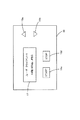
図2はこのスキャンボックス10の外観を平面図により示している。上記LCD17は二行の表示エリアを有しており、操作パネル18は上下カーソルキー18a,18bと、スタートキー18cとストップキー18dとを備えている。本実施形態においては、このLCD17が表示部を構成し、操作パネル18が操作部を構成している。これらは操作性を向上させるために便利であるが、必ずしもこれらが備えられなくても本発明を実現することは可能である。また、表示部としてLEDなどで実現しても良いし、LCD17上にタッチパネルを配設して操作パネル18を構成することも可能である。
【0024】
図1に戻ると、ネットワーク30にはファイルサーバ40が接続されている。ファイルサーバ40は当該ネットワーク30に接続された各クライアントから所定の領域に対するデータの読み書きを可能にするものであり、各領域は階層構造で記憶可能となっており、任意のディレクトリを形成してデータを保存可能となっている。保存領域として、設定情報領域41と、画像領域42とが備えられており、設定情報領域41にはユーザ情報領域41aとジョブ情報41bとが保存され、画像領域には読み取られた画像データが保存されるようになっている。このファイルサーバ40は記憶手段を構成する。本実施形態においては上記階層構造を利用しているが、必ずしも階層構造で管理する必要はない。また、設定情報領域41と画像領域42とは同一の記憶デバイスにある必要はなく、アクセスの頻度に応じて物理的な領域を分けるようにしても良い。
【0025】
クライアント50はネットワーク30に接続された端末であり、オペレーティングシステム51のネットワーク通信機能52を介して上記ネットワーク30とネットワーク通信が可能となっている。また、オペレーティングシステム51を介してスキャンアプリケーション60が実行されている。スキャンアプリケーション60は後述するようにスキャンボックス10に接続されたスキャナ20を制御するものであり、その制御において利用する通信機能としてTCP接続を行うTCP処理部61とUDP処理部62とを備え、また、画像データをファイルサーバ40に保存するためのリモートドライブマッピング機能63を備えている。
【0026】
このクライアント50はスキャナ制御手段を構成している。本実施形態においてはファイルサーバ40とは別のクライアント50上でスキャナ制御手段を実現しているが、ファイルサーバ40で実現することも可能である。
図3はスキャンアプリケーション60の実行フェーズを概略的に示している。画像の読み取りに必要な設定情報を設定するセットアップフェーズ64と、設定されている設定情報に基づいて実行可能か否かをテストするテストフェーズ65と、待機しながら必要に応じて画像の読み取り制御を実行するスレッドフェーズ66とを実行する。また、実際に画像の読み取りを行うスキャニングプロシージャ67はスレッドフェーズ66において実行する。
【0027】
図4はスキャンアプリケーション60のフローチャートを示している。ステップS102ではワークエリアを確保するなどの初期設定を行う。ステップS104では実行するフェーズの選択を受け付ける。選択の受付は図5に示すGUIを表示して行う。画面上には操作入力用としてセットアップボタン71とテストボタン72と待機ボタン73と終了ボタン74とが表示され、エラー内容などを示すメッセージ表示領域75も用意されている
選択はクライアント50の図示しないキーボードやマウスで行われ、選択操作が行われるとステップS106〜ステップS112でどの操作が行われたかによって処理が分岐される。セットアップボタン71が選択されると、処理はステップS114を経てステップS116のセットアップフェーズへと進む。このステップS114については後述する。
【0028】
図6はセットアップフェーズのフローチャートを示している。セットアップフェーズでは図7のユーザ情報・ジョブ情報設定画面を表示する。画面には、スキャンボックスIP表示エリア81、ユーザIP選択ボタン82aと同表示エリア82b、ユーザ名選択ボタン82cと同表示エリア82d、ジョブ番号表示エリア83、原稿選択エリア84、解像度選択エリア85、モード選択エリア86、パスワード入力エリア87、実行ボタン88a、キャンセルボタン88b、追加ボタン89a、修正ボタン89b、削除ボタン89cが表示可能となっている。ただし、これらは常に入力可能となったり選択可能となったりしているわけではなく、入力や選択ができない時期には適宜グレー表示される。例えば、通常はユーザIP選択ボタン82aが選択され、ユーザIP表示エリア82bが利用できるようになっており、ユーザ名表示エリア82dはグレイ表示となって利用できないようになっている。しかし、ユーザ名選択ボタン82cでユーザ名を選択すると、ユーザ名表示エリア82dを利用できるようになり、ユーザIP表示エリア82bがグレイ表示になる。
【0029】
先のステップS114ではスキャンアプリケーション60からネットワーク30に対してブロードキャストを行い、接続されている全てのスキャンボックス10からリプライを得る。複数のスキャンボックス10が接続されている場合でも利用可能とするため、各スキャンボックス10はIPアドレスで管理するようにしており、ステップS114で得られたリプライのIPアドレスを保持してセットアップフェーズへ進行する。セットアップフェーズ200のステップS202では得られているスキャンボックス10のIPアドレスだけをスキャンボックスIP表示エリア81に表示して選択させる。すなわち、複数のスキャンボックス10のIPアドレスが得られていれば同スキャンボックスIP表示エリア81の右端に用意されているアップダウン矢印が有効となり、いずれかをクリックすると他のIPアドレスが表示される。そして、いずれか一つを選択したら実行ボタン88aをクリックすると、選択されたスキャンボックス10とこのクライアント50の関係をステップS204でサーチする。
【0030】
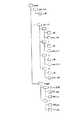
サーチするのはファイルサーバ40の設定情報領域41である。図8はファイルサーバ40のディレクトリ構造を示している。スキャンアプリケーション60に割り当てられたディレクトリscapには三つのディレクトリuser_info,job_info,imageが形成されている。ユーザ情報はディレクトリuser_info 内に保存された図9に示すユーザ情報データベースu_dbとして保存されている。このユーザ情報データベースu_dbには各ユーザごとにクライアント50の端末IPアドレスと、ユーザ名とが対応して保存され、さらに画像データを保存するイメージディレクトリと、設定したジョブ情報を保存するジョブ情報ディレクトリと、異なるIPアドレスのクライアント50からアクセスするためのパスワードとがそれぞれ関連付けて保存されるようになっている。
【0031】
ステップS204では選択されたスキャンボックスのIPアドレスとクライアント50のIPアドレスに基づいてこのユーザ情報データベースu_dbを参照する。まず、クライアント50のIPアドレスに該当するユーザが登録されているか調べ、これが登録されていればジョブ情報ディレクトリを参照して既にジョブ情報が登録されているか判断する。
ここで登録するジョブ情報について説明する。ジョブ情報は図7に示すGUIを利用して設定操作を行ない、ジョブ情報は設定情報領域41内のジョブ情報ディレクトリjob_info内にて形成されたディレクトリごとにまとめて保存されている。このディレクトリは一人のユーザごとに形成されており、ユーザAの場合はディレクトリ..job_info\1が対応していることになる。このディレクトリ..job_info\1には各ユーザごとにジョブ情報をまとめた図10に示す内容のジョブ情報データベースj_dbが保存されているとともに、このディレクトリ..job_info\1から対応するユーザを関連付けるための図11に示すリンク情報ファイルusr_linkも保存されている。
【0032】
ジョブ情報データベースj_dbには、各ジョブに割り当てられた通し番号としてのNOと、使用するスキャンボックスのIPアドレスと、原稿の種類と、読み取りモードとが保存されている。各ユーザは各スキャンボックス10ごとにそれぞれ複数のジョブを設定しておくことができるため、スキャンボックス10のIPアドレスも記入されている。ただし、ジョブ情報を読み出すときには予めスキャンボックス10が選択されているので、IPアドレスが一致するジョブ情報だけが取得の対象となる。
【0033】
従って、ステップS204でクライアント50のIPアドレスが登録されていれば、対応するジョブ情報ディレクトリを参照して上述したジョブ情報データベースj_dbを参照してみる。対応するジョブ情報データベースj_dbもあり、さらにその中で先に選択したスキャンボックス10のIPアドレスが見つかれば「マスタあり」ということになる。また、クライアント50のIPアドレスは登録されていて対応するジョブ情報データベースj_dbもあるが、その中には選択したスキャンボックス10のIPアドレスが見つからない場合、「マスタ以外あり」ということになる。クライアント50のIPアドレスが登録されていなければ「新規」であるし、以上の場合以外は「エラー」である。
【0034】
マスタがある場合は、ステップS208を経てステップS216へと進み、以上のようにしてジョブ情報を取得してステップS218で各ジョブ情報を図7に示すGUIに当てはめて表示する。すなわち、ジョブ番号表示エリア83にはNOを、原稿表示エリア84には原稿の種類を、解像度選択エリア85には解像度を、モード選択エリア86には読み取りモードを表示する。なお、これらはスキャナ20の性能に応じて選択可能なものであり、それぞれの表示エリアの右端に設けられたアップダウン矢印で選択できるようになっている。選択を変えたものは修正ボタン89bで既存のジョブ情報を書き換えることもできるし、追加ボタン89aで新たなジョブ情報として書き加えることもできる。また、不要なジョブは削除ボタン89cで削除することもできる。このようなデータベースの更新はステップS218で行われている。
【0035】
一方、「新規」であればステップS216を経ることなくステップS218に進み、ジョブ情報を入力する。また、「マスタ以外あり」のケースでは、ステップS210を経てステップS212にてパスワードを入力させる。クライアントのIPアドレスがユーザ情報データベースu_dbで見つかっているので、各ユーザに設定してあるパスワードを取得可能であり、これと入力したパスワードとが一致すれば「新規」の場合と同様に当該クライアントのIPアドレスと選択したスキャンボックス10のIPアドレスに対応したジョブ情報を入力する。
【0036】
「エラー」の場合やパスワードが一致しない場合はステップS220やステップS224にてエラー表示し、ステップS222にて図示しないGUIを介してリトライするか選択させ、リトライする場合はステップS202のスキャンボックス10の選択以下を実行し直す。
ステップS218にて設定情報を入力したり、ステップS222にてリトライをしない選択をした場合は当該セットアップフェーズを終了する。なお、この例ではセットアップできる内容をジョブ情報とスキャンボックス10のIPアドレスとしており、イメージディレクトリの所在をディレクトリimageの内部に固定している。しかし、ファイルサーバ40の許容する範囲でイメージディレクトリの所在を設定できるようにしても良い。また、上述したようにユーザ名選択ボタン82cでユーザ名を選択すると、ユーザの特定をIPアドレスに加えてユーザ名で行うこともできるようになる。このようにユーザごとにジョブ情報を登録できれば各ユーザは他のユーザの設定情報の中から自分のものを選択する必要がなくなるので、便利であるが、複数のユーザを登録することは必須の要件ではない。
【0037】
次に、図5の選択画面でテストボタン72を選択すると、処理は図4に示すステップS108を経てステップS118のテストフェーズへと進む。
図12はテストフェーズを示しており、テストフェーズ300のステップS302ではステップS202の場合と同様にしてスキャンボックス10のIPアドレスを選択し、さらにステップS304ではステップS204の場合と同様に選択されたスキャンボックス10とクライアント50のIPアドレスを利用して設定情報領域41をサーチする。すでにジョブ情報が登録されていれば「マスタあり」となり、登録されていなければ「新規」となる。「マスタあり」の場合はステップS306を経てステップS216の場合と同様にステップS312で表示し、ステップS218の場合と同様にステップS314で修正などの操作を行える。また、「新規」の場合はステップS308を経てステップS314にて新規の設定を行える。また、「新規」の場合はステップS310にてエラー表示し、ステップS316にてリトライする。
【0038】
以上のような前準備の処理に対して、図5に示す操作画面から待機ボタン73を選択すると図4に示すステップS110の判断を経てステップS120でレディパケットを待機する。このレディパケットはスキャンボックス10でスタートキー18cを押したときに送出されるようになっているので、スキャンボックス10で読み取りを開始しようとするまで待機することになる。
レディパケットが受信されると、ステップS122で処理のためのスレッドを作成する。スレッドの作成が失敗すると、ステップS124にてエラー表示し、ステップS126でレディパケットに対して理由を付けて返信する。また、スレッドが作成されるとステップS128にてスレッドフェーズを実行する。
【0039】
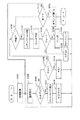
図13はスレッドフェーズ400のフローチャートを示している。また、図14はスキャンボックス10のフローチャートを示しており、図15は読み取り操作の具体的な処理順序を示している。
読み取りを開始するには、スキャンボックス10のスタートキー18cを押す。図14に示すように、スキャンボックス10はステップS502でスタートキー18cが押されたか判断しており、スタートキー18cが押されるとステップS504にてスキャナ20をロックし、ステップS506にてレディパケットをスキャンアプリケーションに送出し、Ackを待機する。
【0040】
スキャンアプリケーションではレディパケットを受信してスレッドフェーズ400が実行され、最初に、ステップS402にてスキャンボックス10のIPアドレスから情報が登録されているかをチェックする。セットアップフェーズを経ていないとスキャンボックス10のIPアドレスは登録されていないはずであり、この場合はステップS404にてNackを送信する。しかし、既に登録されていれば、ステップS406にてレディパケットに対して正常である意味のパケット(Ack)を送信する。
【0041】
スキャンボックス10はステップS508にてパケット(Ack)を受信できるか待機しており、Ackを受信できなければ再度ステップS502にてスタートキー18cが押されるまで待機する。この例では特にエラーメッセージを表示していないが、Nackを受信したときには理由のメッセージを表示するようにしても良い。Ackを受信すると、次のステップS510にてユーザ情報をリクエストするパケットを送信する。
【0042】
スキャンアプリケーションの側では、ステップS408にてスキャンボックス10からの次の指示のパケットを待機しており、リクエスト情報をリクエストするパケットであるとステップS418にてジョブ情報データベースj_dbを参照し、当該スキャンボックス10を一つでも登録しているユーザを探す。具体的には設定情報領域41におけるジョブ情報ディレクトリjob_info内にある全てのディレクトリでジョブ情報データベースj_dbを検索し、スキャンボックス10のIPアドレスが含まれていれば同じディレクトリにあるリンク情報ファイルusr_linkを参照して対応するユーザ情報を取得する。そして、ユーザ情報を取得したら、このユーザ情報をスキャンボックス10に伝えるためにステップS420にてハンドパケットを作成して送信する。
【0043】
この間、スキャンボックス10の側ではステップS512にてユーザ情報のハンドパケットを受信できるまで待機しており、同ハンドパケットを受信するとステップS514にてユーザ情報をLCD17に表示する。複数個のユーザ情報があれば上下カーソルキー18a,18bでスクロールさせて操作者がいずれかを選択できるようにする。そして、スタートキー18cを押したらその時点でのユーザ情報が選択されたものとして受け付ける。
【0044】
ユーザ情報が選択されたらステップS516にてこのユーザ情報を通知しつつスキャンアプリケーションに対してジョブ情報をリクエストする。するとスキャンアプリケーションではステップS414にてジョブ情報のリクエストを受信し、ステップS422にて設定情報領域41におけるユーザ情報データベースu_dbを参照し、該当するユーザ情報に登録されているジョブ情報ディレクトリを突き止める。そして、この登録されているジョブ情報ディレクトリ(..job_info\1)内のジョブ情報データベースj_dbを参照して該当するスキャンボックス10のジョブ情報を取得し、取得されたジョブ情報に基づいてステップS424にてハンドパケットを作成したらステップS426にて同ハンドパケットを送信する。
【0045】
この間、スキャンボックス10の側ではステップS518にてジョブ情報のハンドパケットを受信できるまで待機しており、同ハンドパケットを受信するとステップS520にてジョブ情報をLCD17に表示する。複数個のジョブ情報があれば上下カーソルキー18a,18bでスクロールさせて操作者がいずれかを選択できるようにする。そして、スタートキー18cを押したらその時点でのジョブ情報が選択されたものとして受け付ける。
【0046】
ジョブ情報を選択すると、ユーザ情報とジョブ情報とを含んだパケットが出力され、スキャンアプリケーションの側ではこれを読み取り開始の指示であるGOパケットと判断する。なお、この例では冗長な操作を避けるためにジョブ情報の選択と読み取り開始を同時に処理しているが、別々にスタートキー18cを押し下げるようにしても構わない。
そして、スキャンアプリケーションではGOパケットを受信することによってステップS410の判断を経てステップS428にてリプライパケット(Ack)を送信し、ステップS430にスキャニングを開始する。
【0047】
なお、スキャニングはネットワークTwainの処理で行われる。すなわち、スキャニング中はTCP処理部61を利用してTCP接続モードで画像データの転送を行うが、これ以外のときはUDP処理部62を利用してUDP接続モードで行っている。UDP接続では接続確認を自ら行わなければならないものの、ヘッダが軽いので処理を軽くできる効果がある。また、TCP接続モードではネットワークTwainという共通仕様をそのまま利用できるという効果がある。
【0048】
スキャンボックス10はステップS523にてスキャンアプリケーションからのリプライ(Ack)を待機しており、リプライが得られるとステップS524にて転送モードへ移行する。この転送モードは上記ネットワークTwainの処理であり、スキャンアプリケーションがネットワーク30とスキャンボックス10を介してスキャナ20を制御して画像データを読み取らせるとともに、その画像データをスキャンアプリケーションへと入力させ、さらに、スキャンアプリケーションがブロックごとに分割してファイルサーバ40の画像領域42における各ユーザごとに特定されたイメージディレクトリに記憶させる。むろん、このときの読み取り条件などは上記ジョブ情報で指定されたものである。
【0049】
スキャンボックス10はスキャニングが終了するまで待機しており、ステップS526にてスキャン終了と判断すると、ステップS528にてスキャンアプリケーションにチェックパリティを出力する。上述したようにスキャニング中はTCP接続モードで行われており、その間にスキャニングが正常に終了したか否かをスキャンボックス10は知り得ない。そこで、スキャンアプリケーションの側で正常に終了したか否かを判断させるためにこのチェックパリティを出力する。
【0050】
スキャンアプリケーションでは、チェックパリティが受信されるとステップS416を経てステップS432にてスキャンが正常終了したかチェックする。このためにネットワークTwainでの転送処理についてはフラグを用意しておき、ネットワークTwainの終了結果を同フラグに基づいて判断する。そして、ステップS434にて正常に終了していればAckを、正常に終了していなければNackを出力する。また、正常終了していればステップS436にて本スレッドフェーズを終了するが、正常終了していなければステップS408にて次の処置の指示を待機する。
【0051】
また、スキャンボックス10の側ではAckを受信すれば正常に終了したと判断してステップS532にてスキャナ20を開放(スキャナアンロック)するし、Nackを受信すれば正常に終了できなかったと判断してステップS534にてエラーをLCD17に表示し、ステップS532にてスキャナ20を開放する。
このようにして、スレッドが作成されてスレッドフェーズが実行された場合には、その終了後、ステップS130にてスレッドをクローズして再度ステップS104による選択に復帰する。また、同選択にて終了を選択した場合にはステップS112の判断を経てステップS132にて全てのスレッドを閉じて終了する。
【0052】
次に、上記構成からなる本実施形態の動作を説明する。
スキャンボックス10やスキャナ20が接続された状態で、ユーザはクライアント50のスキャンアプリケーションを起動させる。起動直後はユーザ情報やジョブ情報が設定されていないはずであるから、図5に示す操作画面でセットアップボタン71を選択する。すると、ステップS114にてその時点で接続されているスキャンボックス10のIPアドレスを取得するとともに、ステップS116にてセットアップフェーズを実行し、スキャンボックス10のIPアドレスとクライアント50のIPアドレスに基づいて図7に示すGUIを利用しつつユーザ情報データベースu_dbとジョブ情報データベースj_dbを作成する。
【0053】
このようにしてユーザ情報とジョブ情報とがファイルサーバの設定情報領域41に保存された状態で、クライアント50では待機ボタン73を選択してスキャンアプリケーションを待機状態にさせる。この待機状態では、クライアント50を占有しなければならないという必要はなく、ユーザは他の処理を実行させることもできる。
この後、ユーザはネットワーク30に接続されたスキャンボックス10とスキャナ20の所在地に赴き、スキャナ20に読み取る原稿をセットしてスタートキー18cを押す。このスキャナボックス10は基本的に誰でも使用できるようになっており、各人で読み取り条件が異なることが予想される。このため、ジョブ情報を選択しなければならないが、ジョブ情報はユーザ情報と対応づけて記憶されており、ジョブ情報を絞り込むためにユーザ情報を選択する必要がある。
【0054】
以下は、図15を参照しつつ処理の内容を説明する。ユーザがスキャンボックス10のスタートキー18cを押すと、ステップS506にてレディパケット(a1)が送信され、ステップS508にてこれに対するスキャンアプリケーションからのAck(a2)を受信するとステップS510にてユーザ情報をリクエストする(a3)。すると、スキャンアプリケーションはこのスキャンボックス10を登録しているユーザ情報を返信する(a4)ため、スキャンボックス10はステップS512を経てステップS514にてLCD17上に受信したユーザ情報を表示する。ユーザ情報は実質的にはファイルサーバの検索機能を利用しており、スキャンアプリケーションはファイルサーバ40におけるユーザ情報を検索するリクエスト(b1)を送出すると、検索機能がユーザ情報領域41aを検索して該当するユーザ情報(b2)を出力するようになっている。そして、複数のユーザがLCD17上に表示された場合は、上下カーソルキー18a,18bで自分を選択する。選択したら再度スタートキー18cを押す。すると、ステップS516にて選択したユーザ情報とともにジョブ情報をリクエストするパケット(a5)がスキャンアプリケーションに出力される。
【0055】
スキャンアプリケーションでは、選択されたユーザ情報に基づいてジョブ情報データベースj_dbを選択し、その中でもスキャンボックス10のIPアドレスに該当するジョブ情報だけを返信する。この場合も実際にはファイルサーバ40におけるジョブ情報を検索するリクエスト(b3)を送出すると、検索機能がジョブ情報領域41bを検索して該当するジョブ情報(b4,a6)を出力するようになっている。すると、スキャンボックス10ではステップS520にて受信された複数のジョブ情報をLCD17上に表示し、上下カーソルキー18a,18bによる選択を待機する。また、スタートキー18cが押されればその時点でのユーザ情報とジョブ情報とをステップS522にて選択情報(a7)としてスキャンアプリケーションにパケットを出力する。すると、当該スキャンアプリケーションの側ではこれをGOパケットと解釈し、リプライ(a8)を送信するとともに、そのジョブ情報に基づいてスキャナ20で画像読み取りを行わせるためにステップS430にてスキャニングの制御を実施する。
【0056】
スキャニングはネットワークTwainで実行され、実行中におけるスキャンボックス10は転送モードとなる。そして、転送モードが終了するまで待機する。そして、読み取られた画像データ(a9)はスキャンボックス10を介してネットワーク30上に送出され、所定のブロック単位でファイルサーバ40の画像領域42に保存される。この後、スキャンボックス10ではステップS526にて転送モードが終了したことを検知すると、所望の読み取りが正常に完了したか否かをスキャンアプリケーションに問合せるためにステップS528にてチェックパリティ(a10)を出力する。転送モードはTCPモードで行われ、スキャンアプリケーションがブロック転送してファイルサーバ40に書き込むようになっており、スキャンボックス10が直に判断できないためである。通常は読み取りが順調に完了してAck(a11)が返信され、これによって読み取りを終了する。また、万が一、エラーで読み取りが完了しない場合はスキャンボックス10の側でエラーをLCD17上に表示する。なお、スキャンボックス10による操作の開始時と終了時にはそれぞれスキャナ20に対してステップS504のロック命令(c1)とステップS532のアンロック命令(c2)とが出力されている。
【0057】
このように、スキャンボックス10自体には大容量のストレージを備えなくても、ネットワーク30に接続された他のクライアント50でスキャンアプリケーションを実行させておくことにより、スキャンボックス10からの読み取り開始操作に対応してスキャナ20の読み取り条件などがファイルサーバ40の設定情報領域41から読み出され、同条件でスキャンアプリケーションがスキャナ20を制御しつつ読み取ったデータをファイルサーバ40の画像領域42に転送するので、スキャンボックス10を簡易な構成としつつスキャナ20を多数のユーザで快適に共有することができる。
【図面の簡単な説明】
【図1】 本発明の一実施形態にかかるネットワークスキャナ接続装置のブロック図である。
【図2】 スキャンボックスの平面図である。
【図3】 スキャンアプリケーションの制御内容の概略を示す図である。
【図4】 スキャンアプリケーションの制御内容を示すフローチャートである。
【図5】 スキャンアプリケーションでの選択画面を示す図である。
【図6】 セットアップフェーズの制御内容を示すフローチャートである。
【図7】 ユーザ情報とジョブ情報の設定画面を示す図である。
【図8】 ディレクトリ構造を示す図である。
【図9】 ユーザ情報データベースの内容を示す図である。
【図10】 ジョブ情報データベースの内容を示す図である。
【図11】 リンク情報ファイルの内容を示す図である。
【図12】 テストフェーズの制御内容を示すフローチャートである。
【図13】 スレッドフェーズの制御内容を示すフローチャートである。
【図14】 スキャンボックスの制御内容を示すフローチャートである。
【図15】 読み取り操作の具体的な処理順序を示す図である。
【符号の説明】
10…スキャンボックス
20…スキャナ
30…ネットワーク
40…ファイルサーバ
41…設定情報領域
42…画像領域
50…クライアント
60…スキャンアプリケーション
200…セットアップフェーズ
300…テストフェーズ
400…スレッドフェーズ[0001]
BACKGROUND OF THE INVENTION
The present invention relates to a network scanner connection device, a network scanner connection method, and a medium recording a program for controlling network scanner connection.
[0002]
[Prior art]
Conventionally, a device that includes a hard disk and a control device and connects the scanner to a network has been informed.
According to this apparatus, an image is read by a scanner, and the read image is stored in a hard disk. When there is an access from a terminal connected to the network, the read image data is output.
[0003]
On the other hand, some scanners are connected to a network independently without a hard disk.
[0004]
[Problems to be solved by the invention]
The above-described conventional network scanner connection device has the following problems.
A device with a hard disk or a control device is convenient but expensive. In addition, unless the usage frequency is high, the degree of use of the hard disk is low, and resources are likely to be wasted.
[0005]
In the case of connecting to a network without providing a hard disk, it is necessary to start the application for reading from a client on the network and use the scanner at the place where the scanner is installed. That is, operations at two places are necessary and complicated.
The present invention has been made in view of the above problems, and controls a network scanner connection apparatus, a network scanner connection method, and a network scanner connection that enable a scanner to be used with a simple operation without providing storage in the scanner itself. The purpose is to provide a medium on which the program is recorded.
[0006]
[Means for Solving the Problems]
In order to achieve the above object, the invention according to
[0007]
In the invention according to
That is, the image data read by the scanner is stored in a predetermined area in another storage unit on the same network.
[0008]
Here, the scanner connection unit includes an operation unit, and the scanner control unit monitors the operation of the operation unit included in the scanner connection unit. When a predetermined operation is performed, the scanner is controlled in accordance with the operation. To do.
[0009]
[0010]
[0011]
Further, according to a second aspect of the present invention, in the network scanner connection device according to the first aspect, the scanner control means sets the setting information.
In the invention according to
Further, the invention according to
[0012]
In the invention according to
Furthermore, the invention according to
[0013]
In the invention according to
As an example of such display, the invention according to claim 5 is the network scanner connection device according to
Furthermore, the invention according to claim 6 is the network scanner connection device according to any one of
[0014]
As described above, the method of storing the image data read by the scanner in the storage area connected on the network is not necessarily limited to a substantial apparatus, and it can be easily understood that the method also functions. For this reason, the invention according to claim 7 is configured not as a substantial apparatus but as a method thereof.
By the way, such a network scanner connection device may exist alone or may be used in a state of being incorporated in a certain device, but the idea of the invention is not limited to this and includes various aspects. It is a waste. Therefore, it can be changed as appropriate, such as software or hardware.
[0015]
In the case of computer software as an embodiment of the idea of the invention, it naturally exists on a recording medium on which such software is recorded and must be used. Therefore, the invention according to claim 8 is configured as a medium on which a program for controlling the network scanner connection is recorded.
Of course, the recording medium may be a magnetic recording medium, a magneto-optical recording medium, or any recording medium that will be developed in the future. In addition, the duplication stages such as the primary duplication product and the secondary duplication product are equivalent without any question. In addition, although different from the medium of the present invention, the present invention is used as a result even when it is performed using a communication line as a supply method.
It does not change.
[0016]
Further, even when a part is software and a part is realized by hardware, the idea of the invention is not completely different, and a part is stored on a recording medium and is appropriately changed as necessary. It may be in the form of being read.
When the present invention is implemented by software, a configuration using hardware or an operating system may be used, or may be implemented separately from these.
[0017]
Further, when the present invention is implemented by software, the present invention is not only realized as a medium storing a program, but the present invention is naturally realized as a program itself. Appears.
[0018]
【The invention's effect】
As described above, according to the inventions according to
[0019]
In addition, the operation on the scanner side can be detected, and not only fixed use but also various selection operations can improve the usability.
[0020]
Furthermore, according to the second aspect of the invention, setting information can be easily set.
[0021]
Further, according to the invention of
Furthermore, according to the
Further, according to the fifth aspect of the present invention, even when the reading is not completed, it can be easily known on the scanner installation side and can be read again.
Of course, the technology according to
[0022]
DETAILED DESCRIPTION OF THE INVENTION
Hereinafter, embodiments of the present invention will be described with reference to the drawings.
FIG. 1 is a block diagram showing a network image reading system according to an embodiment of the present invention.
In the figure, a
[0023]
FIG. 2 shows the appearance of the
[0024]
Returning to FIG. 1, a
[0025]
The
[0026]
The
FIG. 3 schematically shows the execution phase of the
[0027]
FIG. 4 shows a flowchart of the
The selection is performed by a keyboard or mouse (not shown) of the
[0028]
FIG. 6 shows a flowchart of the setup phase. In the setup phase, the user information / job information setting screen shown in FIG. 7 is displayed. The screen includes a scan box
[0029]
In the previous step S114, the
[0030]
The setting
[0031]
In step S204, the user information database u_db is referred to based on the IP address of the selected scan box and the IP address of the
Here, the job information to be registered will be described. The job information is set using the GUI shown in FIG. 7, and the job information is collectively stored for each directory formed in the job information directory job_info in the setting
[0032]
The job information database j_db stores NO as a serial number assigned to each job, the IP address of the scan box to be used, the type of document, and the reading mode. Since each user can set a plurality of jobs for each
[0033]
Therefore, if the IP address of the
[0034]
If there is a master, the process proceeds to step S216 through step S208, job information is acquired as described above, and each job information is applied to the GUI shown in FIG. 7 and displayed in step S218. That is, NO is displayed in the job
[0035]
On the other hand, if “new”, the process proceeds to step S218 without passing through step S216, and the job information is input. In the case of “other than master”, the password is input in step S212 through step S210. Since the IP address of the client is found in the user information database u_db, it is possible to obtain the password set for each user, and if this matches the entered password, the client's IP address is the same as in the case of “new”. The job information corresponding to the IP address and the IP address of the selected
[0036]
In the case of “error” or when the passwords do not match, an error is displayed in step S220 or step S224, and whether to retry is selected via a GUI (not shown) in step S222, and in the case of retrying, the
If the setting information is input in step S218, or if it is selected not to retry in step S222, the setup phase ends. In this example, the contents that can be set up are the job information and the IP address of the
[0037]
Next, when the
FIG. 12 shows the test phase. In step S302 of the test phase 300, the IP address of the
[0038]
When the
When the ready packet is received, a thread for processing is created in step S122. If the thread creation fails, an error is displayed in step S124, and a reply is given to the ready packet in step S126. When a thread is created, a thread phase is executed in step S128.
[0039]
FIG. 13 shows a flowchart of the thread phase 400. FIG. 14 shows a flowchart of the
To start reading, the start key 18c of the
[0040]
The scan application receives a ready packet and executes the thread phase 400. First, in step S402, it is checked whether information is registered from the IP address of the
[0041]
The
[0042]
The scan application side waits for the next instruction packet from the
[0043]
During this time, the
[0044]
If user information is selected, job information is requested to the scan application while notifying the user information in step S516. Then, the scan application receives a job information request in step S414, refers to the user information database u_db in the setting
[0045]
During this time, the
[0046]
When job information is selected, a packet including user information and job information is output, and the scan application determines that this is a GO packet that is an instruction to start reading. In this example, job information selection and reading start are processed at the same time in order to avoid redundant operations, but the start key 18c may be pressed separately.
The scan application receives the GO packet, transmits the reply packet (Ack) in step S428 through the determination in step S410, and starts scanning in step S430.
[0047]
Note that scanning is performed in the network Twain process. That is, while scanning, image data is transferred in the TCP connection mode using the
[0048]
The
[0049]
The
[0050]
In the scan application, when the check parity is received, it is checked through step S416 if the scan is normally completed in step S432. Therefore, a flag is prepared for the transfer process in the network Twain, and the end result of the network Twain is determined based on the flag. In step S434, Ack is output if the process is normally completed, and Nack is output if the process is not completed normally. If it has been completed normally, this thread phase is terminated in step S436. If it has not been terminated normally, an instruction for the next treatment is awaited in step S408.
[0051]
Further, if the Ack is received on the
In this way, when the thread is created and the thread phase is executed, the thread is closed in step S130 and the selection is returned to the selection in step S104 again. If the end is selected in the same selection, after determining in step S112, all threads are closed in step S132 and the process is ended.
[0052]
Next, the operation of the present embodiment configured as described above will be described.
The user activates the scan application of the
[0053]
With the user information and job information stored in the setting
Thereafter, the user goes to the location of the
[0054]
The contents of the processing will be described below with reference to FIG. When the user presses the start key 18c of the
[0055]
The scan application selects the job information database j_db based on the selected user information, and returns only the job information corresponding to the IP address of the
[0056]
Scanning is executed in the network Twain, and the
[0057]
As described above, even if the
[Brief description of the drawings]
FIG. 1 is a block diagram of a network scanner connection device according to an embodiment of the present invention.
FIG. 2 is a plan view of a scan box.
FIG. 3 is a diagram illustrating an outline of control contents of a scan application.
FIG. 4 is a flowchart showing control contents of a scan application.
FIG. 5 is a diagram showing a selection screen in a scan application.
FIG. 6 is a flowchart showing control details of a setup phase.
FIG. 7 is a diagram showing a setting screen for user information and job information.
FIG. 8 is a diagram showing a directory structure.
FIG. 9 is a diagram showing the contents of a user information database.
FIG. 10 is a diagram showing the contents of a job information database.
FIG. 11 is a diagram showing the contents of a link information file.
FIG. 12 is a flowchart showing the control content of a test phase.
FIG. 13 is a flowchart showing control contents of a thread phase.
FIG. 14 is a flowchart showing control contents of a scan box.
FIG. 15 is a diagram illustrating a specific processing order of a reading operation.
[Explanation of symbols]
10. Scan box
20 ... Scanner
30 ... Network
40 ... File server
41 ... Setting information area
42 ... image area
50 ... Client
60 ... Scanning application
200 ... Setup phase
300 ... Test phase
400 ... thread phase
Claims (8)
上記ネットワークに接続され、複数のユーザに対応して上記スキャナで読み取りを行なうための設定情報を保存する領域と、複数のユーザに対応して上記スキャナで読み取られた画像データを保存する領域を備える記憶手段と、
上記ネットワークに接続され、上記スキャナ接続手段による操作を監視して上記設定情報の選択操作と上記ユーザの選択操作とを受け付けるとともに、選択されたユーザに対応する上記設定情報に基づいて上記スキャナに対する制御を行ないつつ、上記スキャナで読み取られた画像データを上記スキャナ接続手段と上記ネットワークを介して上記記憶手段において選択されたユーザに対応する領域に保存させるスキャナ制御手段とを具備することを特徴とするネットワークスキャナ接続装置。A scanner connection means including an operation unit and connecting a predetermined scanner to a network;
An area connected to the network for storing setting information for reading by the scanner corresponding to a plurality of users, and an area for storing image data read by the scanner corresponding to a plurality of users. Storage means;
Connected to the network, monitors operations by the scanner connection means, receives the setting information selection operation and the user selection operation, and controls the scanner based on the setting information corresponding to the selected user. And a scanner control means for storing the image data read by the scanner in the area corresponding to the user selected in the storage means via the network and the scanner connection means. Network scanner connection device.
上記スキャナ接続装置に備えた操作部の操作を監視してスキャナで読み取りを行なうための設定情報の選択操作とユーザの選択操作とを受け付けるとともに、上記スキャナ接続装置と上記ネットワークを介して接続された記憶装置における複数のユーザに対応して上記設定情報を記憶する領域に当該選択されたユーザに対応して記憶されている上記設定情報に基づいて上記スキャナに対する制御を行ないつつ、
上記スキャナで読み取られた画像データを、複数のユーザに対応して上記スキャナで読み取られた画像データを保存する領域を備える記憶装置における選択されたユーザに対応する領域に、上記スキャナ接続装置と上記ネットワークを介して保存させることを特徴とするネットワークスキャナ接続方法。A network scanner connection method for reading image data with a scanner connected to a network via a predetermined scanner connection device,
The operation of the operation unit provided in the scanner connection device is monitored and a setting information selection operation and a user selection operation for reading by the scanner are accepted, and the scanner connection device is connected to the scanner connection device via the network. While controlling the scanner based on the setting information stored corresponding to the selected user in the area for storing the setting information corresponding to a plurality of users in the storage device,
The scanner connection device and the image data read by the scanner in an area corresponding to a selected user in a storage device including an area for storing image data read by the scanner corresponding to a plurality of users. A method for connecting to a network scanner, characterized by storing the data via a network.
上記スキャナ接続装置に備えた操作部の操作を監視してスキャナで読み取りを行なうための設定情報の選択操作とユーザの選択操作とを受け付けるとともに、上記スキャナ接続装置と上記ネットワークを介して接続された記憶装置における複数のユーザに対応して上記設定情報を記憶する領域に当該選択されたユーザに対応して記憶されている上記設定情報に基づいて上記スキャナに対する制御を行ないつつ、
上記スキャナで読み取られた画像データを、複数のユーザに対応して上記スキャナで読み取られた画像データを保存する領域を備える上記記憶装置における選択されたユーザに対応する領域に、上記スキャナ接続装置と上記ネットワークを介して保存させる機能をコンピュータに実現させることを特徴とするネットワークスキャナ接続を制御するプログラムを記録した媒体。A medium recording a program for controlling a network scanner connection for reading image data using a scanner connected to a network via a predetermined scanner connection device,
The operation of the operation unit provided in the scanner connection device is monitored and a setting information selection operation and a user selection operation for reading by the scanner are accepted, and the scanner connection device is connected to the scanner connection device via the network. While controlling the scanner based on the setting information stored corresponding to the selected user in the area for storing the setting information corresponding to a plurality of users in the storage device,
The scanner connection device and the image data read by the scanner in an area corresponding to a selected user in the storage device, which includes an area for storing image data read by the scanner corresponding to a plurality of users. A medium having recorded thereon a program for controlling connection of a network scanner, characterized in that a computer realizes a function of saving via the network.
Priority Applications (1)
| Application Number | Priority Date | Filing Date | Title |
|---|---|---|---|
| JP2000091335A JP3915865B2 (en) | 2000-03-29 | 2000-03-29 | Network scanner connection device, network scanner connection method, and medium storing program for controlling network scanner connection |
Applications Claiming Priority (1)
| Application Number | Priority Date | Filing Date | Title |
|---|---|---|---|
| JP2000091335A JP3915865B2 (en) | 2000-03-29 | 2000-03-29 | Network scanner connection device, network scanner connection method, and medium storing program for controlling network scanner connection |
Related Child Applications (1)
| Application Number | Title | Priority Date | Filing Date |
|---|---|---|---|
| JP2006328463A Division JP4348559B2 (en) | 2006-12-05 | 2006-12-05 | Network scanner connection device, network scanner connection method, medium storing scanner for controlling network scanner connection, and scanner |
Publications (3)
| Publication Number | Publication Date |
|---|---|
| JP2001285560A JP2001285560A (en) | 2001-10-12 |
| JP2001285560A5 JP2001285560A5 (en) | 2005-05-19 |
| JP3915865B2 true JP3915865B2 (en) | 2007-05-16 |
Family
ID=18606805
Family Applications (1)
| Application Number | Title | Priority Date | Filing Date |
|---|---|---|---|
| JP2000091335A Expired - Fee Related JP3915865B2 (en) | 2000-03-29 | 2000-03-29 | Network scanner connection device, network scanner connection method, and medium storing program for controlling network scanner connection |
Country Status (1)
| Country | Link |
|---|---|
| JP (1) | JP3915865B2 (en) |
Families Citing this family (3)
| Publication number | Priority date | Publication date | Assignee | Title |
|---|---|---|---|---|
| JP3811085B2 (en) * | 2002-03-18 | 2006-08-16 | 株式会社Pfu | Scanner system |
| EP1422920B1 (en) | 2002-11-19 | 2013-01-23 | Canon Denshi Kabushiki Kaisha | Network scanning system |
| JP2019077071A (en) * | 2017-10-23 | 2019-05-23 | 富士ゼロックス株式会社 | Information processor, information processing system, and program |
-
2000
- 2000-03-29 JP JP2000091335A patent/JP3915865B2/en not_active Expired - Fee Related
Also Published As
| Publication number | Publication date |
|---|---|
| JP2001285560A (en) | 2001-10-12 |
Similar Documents
| Publication | Publication Date | Title |
|---|---|---|
| US6493743B2 (en) | PDA workspace interface using application icons for downloading remote user file | |
| JP3946275B2 (en) | Remote installation system and method | |
| JP3777025B2 (en) | System resource display device and method thereof | |
| JP4958671B2 (en) | License management apparatus, license management method, and computer program | |
| US7884954B2 (en) | Peripheral equipment and management method thereof | |
| JP5444870B2 (en) | Image forming apparatus, processing method thereof, and program | |
| US6945717B2 (en) | Printer, printer system, printer control method, and program therefor | |
| CN101276263A (en) | Information processing apparatus and information processing system | |
| US7061633B1 (en) | Printer and network printing system | |
| JP2008152691A (en) | Information processing apparatus, printer and network printing system | |
| US9270844B2 (en) | Image processing apparatus, control method, and storage medium that complement a domain to an address data item with no domain name | |
| US7080166B2 (en) | Multifunctional apparatus, information processing apparatus, data processing method, and computer program product executed by the multifunctional apparatus or the information processing apparatus | |
| JP3915865B2 (en) | Network scanner connection device, network scanner connection method, and medium storing program for controlling network scanner connection | |
| JP4348559B2 (en) | Network scanner connection device, network scanner connection method, medium storing scanner for controlling network scanner connection, and scanner | |
| JPH10171634A (en) | Information processing terminal and program updating system | |
| JP2001285560A5 (en) | ||
| JPH10275132A (en) | Data processor and storage medium | |
| JP2018011183A (en) | Information processor, server device, system, information processing method, and program | |
| JP2018073115A (en) | Relay apparatus, program for relay apparatus, and information processing system | |
| JP2008152363A (en) | Image processor, folder management method and computer program | |
| JP2006115222A (en) | Image processing apparatus, control method thereof, and computer program | |
| JP4730055B2 (en) | Information processing apparatus, setting change method, and setting change program | |
| JPH08227453A (en) | Decentralized image editing system | |
| JP4859241B2 (en) | Composite apparatus, information processing method, and program | |
| JPS63276158A (en) | Password input control system |
Legal Events
| Date | Code | Title | Description |
|---|---|---|---|
| A521 | Written amendment |
Free format text: JAPANESE INTERMEDIATE CODE: A523 Effective date: 20040707 |
|
| A621 | Written request for application examination |
Free format text: JAPANESE INTERMEDIATE CODE: A621 Effective date: 20040707 |
|
| A977 | Report on retrieval |
Free format text: JAPANESE INTERMEDIATE CODE: A971007 Effective date: 20050909 |
|
| A131 | Notification of reasons for refusal |
Free format text: JAPANESE INTERMEDIATE CODE: A131 Effective date: 20051122 |
|
| A521 | Written amendment |
Free format text: JAPANESE INTERMEDIATE CODE: A523 Effective date: 20060117 |
|
| A02 | Decision of refusal |
Free format text: JAPANESE INTERMEDIATE CODE: A02 Effective date: 20061004 |
|
| A521 | Written amendment |
Free format text: JAPANESE INTERMEDIATE CODE: A523 Effective date: 20061206 |
|
| A911 | Transfer to examiner for re-examination before appeal (zenchi) |
Free format text: JAPANESE INTERMEDIATE CODE: A911 Effective date: 20061219 |
|
| TRDD | Decision of grant or rejection written | ||
| A01 | Written decision to grant a patent or to grant a registration (utility model) |
Free format text: JAPANESE INTERMEDIATE CODE: A01 Effective date: 20070117 |
|
| A61 | First payment of annual fees (during grant procedure) |
Free format text: JAPANESE INTERMEDIATE CODE: A61 Effective date: 20070130 |
|
| R150 | Certificate of patent or registration of utility model |
Free format text: JAPANESE INTERMEDIATE CODE: R150 |
|
| FPAY | Renewal fee payment (event date is renewal date of database) |
Free format text: PAYMENT UNTIL: 20110216 Year of fee payment: 4 |
|
| FPAY | Renewal fee payment (event date is renewal date of database) |
Free format text: PAYMENT UNTIL: 20110216 Year of fee payment: 4 |
|
| FPAY | Renewal fee payment (event date is renewal date of database) |
Free format text: PAYMENT UNTIL: 20120216 Year of fee payment: 5 |
|
| FPAY | Renewal fee payment (event date is renewal date of database) |
Free format text: PAYMENT UNTIL: 20130216 Year of fee payment: 6 |
|
| FPAY | Renewal fee payment (event date is renewal date of database) |
Free format text: PAYMENT UNTIL: 20130216 Year of fee payment: 6 |
|
| S531 | Written request for registration of change of domicile |
Free format text: JAPANESE INTERMEDIATE CODE: R313531 |
|
| R350 | Written notification of registration of transfer |
Free format text: JAPANESE INTERMEDIATE CODE: R350 |
|
| LAPS | Cancellation because of no payment of annual fees |