JP3901034B2 - Vehicle door opening and closing device - Google Patents
Vehicle door opening and closing device Download PDFInfo
- Publication number
- JP3901034B2 JP3901034B2 JP2002183194A JP2002183194A JP3901034B2 JP 3901034 B2 JP3901034 B2 JP 3901034B2 JP 2002183194 A JP2002183194 A JP 2002183194A JP 2002183194 A JP2002183194 A JP 2002183194A JP 3901034 B2 JP3901034 B2 JP 3901034B2
- Authority
- JP
- Japan
- Prior art keywords
- door
- vehicle
- light emitting
- vehicle door
- emitting member
- Prior art date
- Legal status (The legal status is an assumption and is not a legal conclusion. Google has not performed a legal analysis and makes no representation as to the accuracy of the status listed.)
- Expired - Fee Related
Links
Images


Classifications
-
- E—FIXED CONSTRUCTIONS
- E05—LOCKS; KEYS; WINDOW OR DOOR FITTINGS; SAFES
- E05B—LOCKS; ACCESSORIES THEREFOR; HANDCUFFS
- E05B81/00—Power-actuated vehicle locks
- E05B81/54—Electrical circuits
- E05B81/64—Monitoring or sensing, e.g. by using switches or sensors
- E05B81/76—Detection of handle operation; Detection of a user approaching a handle; Electrical switching actions performed by door handles
- E05B81/78—Detection of handle operation; Detection of a user approaching a handle; Electrical switching actions performed by door handles as part of a hands-free locking or unlocking operation
-
- B—PERFORMING OPERATIONS; TRANSPORTING
- B60—VEHICLES IN GENERAL
- B60R—VEHICLES, VEHICLE FITTINGS, OR VEHICLE PARTS, NOT OTHERWISE PROVIDED FOR
- B60R25/00—Fittings or systems for preventing or indicating unauthorised use or theft of vehicles
- B60R25/20—Means to switch the anti-theft system on or off
- B60R25/24—Means to switch the anti-theft system on or off using electronic identifiers containing a code not memorised by the user
- B60R25/246—Means to switch the anti-theft system on or off using electronic identifiers containing a code not memorised by the user characterised by the challenge triggering
-
- G—PHYSICS
- G07—CHECKING-DEVICES
- G07C—TIME OR ATTENDANCE REGISTERS; REGISTERING OR INDICATING THE WORKING OF MACHINES; GENERATING RANDOM NUMBERS; VOTING OR LOTTERY APPARATUS; ARRANGEMENTS, SYSTEMS OR APPARATUS FOR CHECKING NOT PROVIDED FOR ELSEWHERE
- G07C9/00—Individual registration on entry or exit
- G07C9/00174—Electronically operated locks; Circuits therefor; Nonmechanical keys therefor, e.g. passive or active electrical keys or other data carriers without mechanical keys
- G07C9/00309—Electronically operated locks; Circuits therefor; Nonmechanical keys therefor, e.g. passive or active electrical keys or other data carriers without mechanical keys operated with bidirectional data transmission between data carrier and locks
-
- E—FIXED CONSTRUCTIONS
- E05—LOCKS; KEYS; WINDOW OR DOOR FITTINGS; SAFES
- E05B—LOCKS; ACCESSORIES THEREFOR; HANDCUFFS
- E05B17/00—Accessories in connection with locks
- E05B17/10—Illuminating devices on or for locks or keys; Transparent or translucent lock parts; Indicator lights
-
- E—FIXED CONSTRUCTIONS
- E05—LOCKS; KEYS; WINDOW OR DOOR FITTINGS; SAFES
- E05B—LOCKS; ACCESSORIES THEREFOR; HANDCUFFS
- E05B81/00—Power-actuated vehicle locks
- E05B81/54—Electrical circuits
- E05B81/64—Monitoring or sensing, e.g. by using switches or sensors
- E05B81/76—Detection of handle operation; Detection of a user approaching a handle; Electrical switching actions performed by door handles
- E05B81/77—Detection of handle operation; Detection of a user approaching a handle; Electrical switching actions performed by door handles comprising sensors detecting the presence of the hand of a user
-
- G—PHYSICS
- G07—CHECKING-DEVICES
- G07C—TIME OR ATTENDANCE REGISTERS; REGISTERING OR INDICATING THE WORKING OF MACHINES; GENERATING RANDOM NUMBERS; VOTING OR LOTTERY APPARATUS; ARRANGEMENTS, SYSTEMS OR APPARATUS FOR CHECKING NOT PROVIDED FOR ELSEWHERE
- G07C9/00—Individual registration on entry or exit
- G07C9/00174—Electronically operated locks; Circuits therefor; Nonmechanical keys therefor, e.g. passive or active electrical keys or other data carriers without mechanical keys
- G07C2009/00753—Electronically operated locks; Circuits therefor; Nonmechanical keys therefor, e.g. passive or active electrical keys or other data carriers without mechanical keys operated by active electrical keys
- G07C2009/00769—Electronically operated locks; Circuits therefor; Nonmechanical keys therefor, e.g. passive or active electrical keys or other data carriers without mechanical keys operated by active electrical keys with data transmission performed by wireless means
- G07C2009/00793—Electronically operated locks; Circuits therefor; Nonmechanical keys therefor, e.g. passive or active electrical keys or other data carriers without mechanical keys operated by active electrical keys with data transmission performed by wireless means by Hertzian waves
-
- G—PHYSICS
- G07—CHECKING-DEVICES
- G07C—TIME OR ATTENDANCE REGISTERS; REGISTERING OR INDICATING THE WORKING OF MACHINES; GENERATING RANDOM NUMBERS; VOTING OR LOTTERY APPARATUS; ARRANGEMENTS, SYSTEMS OR APPARATUS FOR CHECKING NOT PROVIDED FOR ELSEWHERE
- G07C2209/00—Indexing scheme relating to groups G07C9/00 - G07C9/38
- G07C2209/60—Indexing scheme relating to groups G07C9/00174 - G07C9/00944
- G07C2209/62—Comprising means for indicating the status of the lock
-
- G—PHYSICS
- G07—CHECKING-DEVICES
- G07C—TIME OR ATTENDANCE REGISTERS; REGISTERING OR INDICATING THE WORKING OF MACHINES; GENERATING RANDOM NUMBERS; VOTING OR LOTTERY APPARATUS; ARRANGEMENTS, SYSTEMS OR APPARATUS FOR CHECKING NOT PROVIDED FOR ELSEWHERE
- G07C2209/00—Indexing scheme relating to groups G07C9/00 - G07C9/38
- G07C2209/60—Indexing scheme relating to groups G07C9/00174 - G07C9/00944
- G07C2209/63—Comprising locating means for detecting the position of the data carrier, i.e. within the vehicle or within a certain distance from the vehicle
- G07C2209/65—Comprising locating means for detecting the position of the data carrier, i.e. within the vehicle or within a certain distance from the vehicle using means for sensing the user's hand
Landscapes
- Engineering & Computer Science (AREA)
- Computer Networks & Wireless Communication (AREA)
- Physics & Mathematics (AREA)
- General Physics & Mathematics (AREA)
- Mechanical Engineering (AREA)
- Lock And Its Accessories (AREA)
Description
【0001】
【発明の属する技術分野】
本発明は、人の車両への接近を検出し、車両ドアの開作動がなされた場合に車両ドアを解錠し、車両ドアの閉作動がなされた場合に施錠する車両用ドア開閉装置に関する。
【0002】
【従来の技術】
従来より、車両において車両ドアの開閉を行う、リモコンと称される携帯機を人(通常は運転者)が携帯し、人が車両ドアに接近または離間する状態を検出して、自動的に車両ドアの施錠または解錠を行う車両用ドア開閉装置が知られている。このような車両用ドア開閉装置におけるロッキングシステム(スマートエントリーシステム)は、利便性および安全性の向上をねらったものであり、特開2000−160897号公報に記載されている。
【0003】
上記の従来技術では、車両ドアを自動的に解錠・施錠することについては開示されているが、車両ドアの解錠・施錠の状態を人に対して報知することについては何ら開示されていない。車両ドアの状態を報知することなく実際に車両ドアが施錠されているか否かを人が確認することは非常に困難な場合がある。そのため、車両ドアが施錠或いは解錠されたことを何らかの手段で人に報知する必要がある。
【0004】
特開2000−45593号には、車両ドアの解錠・施錠に際し、車両周囲の明るさに対応して車内照明、ヘッドランプ、テールランプ等の発光量或いは光質を定めて光制御信号を出力したり、車両周囲の明るさに対応してブザーの発音量或いは音質を定めて音制御信号を出力したりすることが開示されている。具体的には、昼間のように周囲が明るい時には発光のみでは認識が困難な場合があるため、発光を抑えてブザーによる発音を併せて行うようにし、夕暮れや夜間のように周囲が暗い時にはブザーの発音を抑えて発光を併せて行うようにしている。これによると、車両ドアの解錠或いは施錠の状態を容易に人に報知することができる。
【0005】
【発明が解決しようとする課題】
しかしながら、上述した特開2000−45593号に開示される技術の報知では、室内照明やヘッドランプ、テールランプは、人が車両ドアを開閉するときに操作するドアハンドルから離間した箇所に設けられている。従って、人がドアハンドルを操作することによって自動的に解錠或いは施錠する形式の車両用ドア開閉装置では、人の視認度の観点から、車両ドアの状態を人が確実に認識できるとは限らない、という問題がある。
【0006】
そこで本発明は、上述した問題を解決すべく、車両ドアの解錠・施錠の状態を人が確実に認識できるように報知を行うことが可能な車両用ドア開閉装置を提供することを技術的課題とする。
【0007】
【課題を解決するための手段】
上記の課題を解決するため請求項1の発明は、車両ドアの開閉を行うドアハンドルと、車両ドアの施錠及び解錠を行うドアロック機構と、車外に向けて車外リクエスト信号を送信する第1送信アンテナと、車内に向けて車内リクエスト信号を送信する第2送信アンテナと、前記ドアハンドルの操作に基づいて車両ドアの開閉意思を検出する検出手段と、携帯機から車外リクエスト信号に基づくID情報信号を受信した場合に、携帯機が車両に近づいたとしてドア解錠モードに移行し、このドア解錠モード中に前記検出手段が車両ドアの解錠意思を検出したときに前記ドアロック機構を解錠させる一方、携帯機から車内リクエスト信号に基づくID情報信号の受信が途絶えた場合に、前記携帯機が車内から車外へ出たとしてドア施錠モードに移行し、該ドア施錠モード中に前記検出手段が車両ドアの施錠意思を検出したときに前記ドアロック機構を施錠させる制御機構と、を備える車両用ドア開閉装置であって、前記ドアハンドルは、該ドアハンドルの外部から確認可能な発光部材を内蔵し、前記制御機構は、前記ドア開錠モードおよび前記ドア施錠モードへの移行時に前記発光部材を発光させるとともに、前記ドアロック機構の作動に連動して前記発光部材の発光状態を変化させることを特徴とする車両用ドア開閉装置とした。
【0008】
請求項1における制御機構は、人(主に運転者)によるドアハンドルの操作に基づいて車両ドアの開閉を認識しているので、ドアハンドルの操作に基づいてドアロック機構が作動される。つまり、ドアロック機構の作動は人によるドアハンドルの操作に連動することとなり、車両ドアの解錠・施錠は人がドアハンドルを操作することに連動して行われる。したがって、発光部材が発光するのは人がドアハンドルを操作する前後であり、ドアハンドルに内蔵された発光部材の発光に対しての人の視認度は比較的高く、また、ドアロック機構の作動に連動して発光部材の発光状態が変化されるため、車両ドアの状態が確実に人に報知される。
【0009】
【発明の実施の形態】
以下、本発明の実施形態を図面を参照して説明する。図1は本発明の車両用ドア開閉装置を車両のキーレスエントリーシステム(スマートエントリーシステムともいう)1(ドア開閉装置)に適用した場合の車両側でのシステムブロック図である。このシステム1は、第1にリモコンと称される携帯機60(図2示)を携帯するユ人(主に運転者)が車両に対して接近あるいは離間しているかを判定する。判定の結果、接近していると判定された場合であって、人がドアハンドルを操作すると、車両ドア近傍に取り付けられたドアロック機構11により、ドアの施錠(ロック)/解錠(アンロック)を切り替え可能とするものである。この切り替えは、車両キーの操作を必要としないものである。
【0010】
このシステム1の構成について説明する。ドアパネルには、車両ドアを解錠・施錠するドアロック機構11、ドアロック機構11の作動を制御するドアECU12、ドアパネルの車外側に取り付けられるとともに、車外と通信を行う第1送信アンテナ21を内蔵するドアハンドル20、ドアハンドル20の第1送信アンテナ21と接続する第1オシレータ30とが設けられている。後述するように、ドアハンドル20には、第1送信アンテナ21のほかに、ドア解錠用検出センサ電極22、ドア施錠用検出センサ電極23及び発光部材24が内蔵されている。
【0011】
車内には、車内での通信を行う第2送信アンテナ41と、第2送信アンテナ41と接続する第2オシレータ42と、受信チューナー43と、システムECU44とが設けられている。第2送信アンテナ41は車室のセンターコンソール等の電波が車内に放射できる場所に設けられ、システムECU44は第2オシレータ42及び受信チューナー43と接続している。受信チューナー43は車内のインナーミラー等に取り付けられている。
【0012】
このシステム1では、イグニッション等のスイッチ操作を検出する操作検出部51、ドアの開閉を検出するドア開閉検出部52、及び車速や窓の開閉を各種センサ電極により検出するセンサ電極群53がシステムECU44に接続される。尚、本実施形態のドアECU12とシステムECU44とが特許請求の範囲に記載の制御機構に相当する構成である。本実施形態ではシステム全体の制御を行うシステムECU44と、ドアロック機構11の作動を制御するドアECU12とを別体で設けているが、これらECU44、12を一体のECUとして設けてもよい。
【0013】
更にこのシステム1では、スマートシステムECU44がエンジン54、ステアリングロック部55及びイモビライザ部56と接続している。ステアリングロック部55は、ステアリング操作を機械的にロックして禁止する機能をもつものである。イモビライザ部56は、エンジン54への燃料供給を禁止したり、不正使用時にイグニッション動作を禁止したりする機能をもつものである。また、スマートシステムECU44内のエンジン制御部(図示無し)により、車両のエンジン54の制御が行われる。
【0014】
システムECU44は第1オシレータ30と第2オシレータ42に各々リクエスト信号(車外リクエスト信号及び車内リクエスト信号)を送信する。本実施の形態においては、134kHzのリクエスト信号が第1送信アンテナ21と第2送信アンテナ41から携帯機60に対して、車外リクエスト信号および室内リクエスト信号として送信される。
【0015】
また、携帯機60から出力されるID情報信号は受信チューナー43で受信される。本実施の形態では、ID情報信号は、315MHzの周波数となっている。この信号は、受信チューナー43で復調されてシステムECU44に入力される。システムECU44は車両ドアの解錠・施錠を行うコード、エンジン54の始動を行うコード、トランスポンダのID照合のコード等のコードを電源が遮断された状態でもメモリ45内に記憶できる機能をもつ。
【0016】
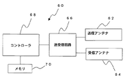
図2に本システム1で使用する携帯機60のブロック図を示す。携帯機60は、送信アンテナ62と受信アンテナ64を有している。送信アンテナ62は、315MHzでID情報信号を車両に対して送信するものである。受信アンテナ64は、車両から送信された134kHzのIDリクエスト信号を受信するものである。送信アンテナ62と受信アンテナ64は、コントローラ68に接続される送受信回路66に接続されている。
【0017】
携帯機60の受信アンテナ64で受信された車両側からのリクエスト信号(車外リクエスト信号)は、送受信回路66で復調されてコントローラ68に入力される。コントローラ68はメモリ70の内部に記憶されたコードを送受信回路66に送信する。このコードは、ID情報を含むものであり、送受信回路66で変調され、315MHzの信号で送信アンテナ62から車両の受信チューナー43に対して送信する。
【0018】
上述したシステム1の動作について説明する。車両の駐車時は、システムECU44からドアパネル内の第1オシレータ30にリクエスト信号を送信し、第1送信アンテナ21から車外に向けて車外リクエスト信号(134kHz)が電波として送信される。人が携帯機60とともに車両に近づくと、携帯機60の受信アンテナ64が車両からの車外リクエスト信号を受信して、送受信回路66を介してコントローラ68が車外リクエスト信号を処理し、送信アンテナ62からID情報信号(315MHz)を送信する。受信チューナー43がID情報信号を受信してシステムECU44に伝送することで、システムECU44は携帯機60が車両に近づいたことを認識する。携帯機60が近づいたことを認識すると、人による車両ドアの開動作を確認するため、システムECU44はドア解錠モードに移行する。
【0019】
ドア解錠モードでは、システムECU44から第1オシレータ30を介してドア解錠用センサ電極22による検出が行われる。また、ドア解錠モードに移行すると、第1オシレータ30を介して発光部材24が連続的に発光する。これにより、車両が携帯機60からのID情報信号を認識したことを、人が視認できる。
【0020】
この状態から人がドアハンドル20を握ると、ドア解錠用センサ電極22から第1オシレータ30を介してシステムECU44にセンス信号が送信される。システムECU44がセンス信号を処理し、ドアECU12にドア解錠信号が送信され、ドアロック機構11が車両ドアを解錠作動する。ここで、システムECU44がセンス信号を受信してドアロック機構11が車両ドアを解錠すると、発光部材24を発光させるための信号が第1オシレータ30を介して発光部材24に送信され、発光部材24を点滅して発光させる。これにより、車両ドアが解錠されたことを人が視認できる。
【0021】
次に、人が車内から車外へ出るときのシステム1の動作について説明する。人が車内にいるときには、システムECU44から第2オシレータ42にリクエスト信号を送信し、第2送信アンテナ41から車内に向けてリクエスト信号が電波として送信される。携帯機60が車内にあるときには、第2送信アンテナ41からのリクエスト信号が携帯機60内で受信され、送信アンテナ62から送信されるID情報信号が受信チューナー43で受信される。この状態から人が車両ドアを開けて車外に出ると、携帯機60は、第2オシレータ42と第2送信アンテナ41からのリクエスト信号を受信できなくなる。そのため、第2送信アンテナ41からのリクエスト信号に基づくID情報信号の送信が途絶え、システムECU44は、携帯機60が車内から車外へ出た(人が降車した)ことを認識する。携帯機60が車内から車外へ出て車両ドアが閉じられると、システムECU44は、ドア施錠モードへと移行する。
【0022】
ドア施錠モードでは、システムECU44から第1オシレータ30を介してドア施錠用センサ電極23による検出が行われる。また、ドア施錠モードに移行すると、第1オシレータ30を介して発光部材24が点滅して発光する。これにより、車両ドアが施錠可能な状態(人がドアハンドル20を操作すると施錠される状態)であることを、人が視認できる。
【0023】
この状態から人がドアハンドル20に触れると、ドア施錠用センサ電極23から第1オシレータ30を介してシステムECU44にロック信号が送信される。そしてシステムECU44がロック信号を処理して第1オシレータ30にリクエスト信号を送信し、第1送信アンテナ21から車外にリクエスト信号を電波として送信する。このとき、人は携帯機60とともに車外の車両ドア近傍にいるので、携帯機60からID情報信号が送信される。車両側では受信チューナー43がID情報信号を受信し、システムECU44に送信する。このようにして人(携帯機60)が車外であることが確認されると、システムECU44はドアECU12にドア施錠信号を送信して、ドアロック機構11が車両ドアを施錠作動する。ここで、システムECU44がロック信号を受信すると、発光部材24を発光させるための信号が第1オシレータ30を介して発光部材24に送信され、発光部材24を点灯して発光させる。これにより、車両ドアが施錠されたことを人が視認できる。
【0024】
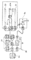
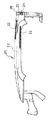
次に、図3及び図4を参照し、第1オシレータ30及びドアパネルに取り付けられるドアハンドル20について更に詳細に説明する。図3はドアハンドル20及び第1オシレータ30を説明するためのブロック図、図4はドアハンドル20の断面概略図である。図4に示すように、ドアハンドル20は中央のグリップ部GPを手で握り、これを動作させることにより車両ドアを開作動可能とするグリップ型ハンドルである。尚、本実施形態では、ドアハンドル20をグリップ型ハンドルとしているが、これに限定されないものとする。
【0025】
第1オシレータ30は、送信用アンプ31と、センサ電極ドライバ32と、発光部材用ドライバ33とにより構成されている。システムECU44から出力される車外リクエスト信号は、CLG端子に入力されて送信用アンプ31にて変調増幅され、ANT1端子、ANT2端子にそれぞれ接続された第1送信アンテナ21に送られ、電波として車外に送信される。ドア解錠検出モード及びドア施錠検出モード時にシステムECU44から出力される信号は、SEL端子に入力され、SEL端子に接続されたセンサ電極ドライバ32を起動する。センサ電極ドライバ32は、SGT1端子を介してドア施錠用センサ電極23の検出を、SGT2端子を介してドア解錠用センサ電極22の検出をそれぞれ行う。尚、第1送信アンテナ21、両センサ電極22、23及び発光部材24と各端子とは信号線にて電気的に接続されている。
【0026】
第1送信アンテナ21は、直方体状のフェライトコア21Aと、フェライトコア21Aの長手方向に対して垂直に巻かれたコイル21Bとで構成されている。ドア施錠用センサ電極23は、静電容量式センサ電極であり、ドアハンドル20の表側(図4の上側)に内蔵されて、人が車両ドアを閉じる際におけるドアハンドル20の操作(ドアハンドル20との接触)を認識できるようになっている。ドア解錠用センサ電極22は、静電容量式センサ電極であり、ドアハンドル20の裏側(図4の下側)に内蔵されて、人が車両ドアを開ける際におけるドアハンドル20の操作(ドアハンドル20との接触)を認識できるようになっている。尚、本実施形態では、これらのセンサ電極22、23は、人がドアハンドル20に接触したときの静電容量の変化により人によるドアハンドル20の操作を検出する静電容量式センサ電極としているが、これに限定されるものではなく、例えば、人によるオン操作を検出する操作スイッチであってもよい。
【0027】
人が車両ドアを開ける際には、人の手がドアハンドル20を握ってドアハンドル20を引っ張るため、人の手はドアハンドル20の裏側に接触する。これにより、ドア解錠用センサ電極22は人のドアハンドル操作による車両ドアの開動作を検出する。このときのSGT2端子からの信号の変化をセンサ電極ドライバ32が検出し、SENS端子を介してシステムECU44にセンス信号を送信する。また、人が車両ドアを閉める際には、人の手がドアハンドル20の表側に接触するので、ドア施錠用センサ電極23は人のドアハンドル操作による車両ドアの閉動作を検出する。このときのSGT1端子からの信号の変化をセンサ電極ドライバ32が検出し、SENS端子を介してシステムECU44にロック信号を送信する。発光部材24を発光させるときには、システムECU44から第1オシレータ30のILM1端子に信号が送信されて発光部材用ドライバ33を起動し、ILM2端子を介して発光部材24を連続的に或いは点滅して発光させる。
【0028】
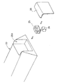
ドアハンドル20に内蔵される発光部材24について説明する。図5は、本実施形態のドアハンドル20における発光部材24を含む箇所の断面図、図6は発光部材24のドアハンドル20への取り付けを示す斜視図である。図6では、発光部材24と電気的に接続する信号線は省略している。本実施形態では、発光部材24として高輝度LEDを用いている。この高輝度LED24はケース状の光拡散樹脂25に覆われて、更に光拡散樹脂25を覆う透明アクリル26とともに、ドアハンドル20の端部に形成される収容部20Aに収容されている。光拡散樹脂25は光の拡散を抑える作用をもつ樹脂であり、光拡散樹脂25で高輝度LED24を覆うことによって高輝度LED24の発光が拡散されにくくなり、車両の周囲の明るさにかかわらず人が高輝度LED24の発光を認識できるようになる。本実施形態における発光部材24の変形例を図7に示す。図7の変形例は、発光部材24として、第1LED24Aと、第1LED24Aとは異なる光質を発光する第2LED24Bとを組み合わせた例を示しており、それ以外の構成については図5及び図6に示した実施形態と同一である。この例をシステム1に用いることで、車両ドアの状態に応じて発光する光質を変化させることが可能になる。例えば、車両ドアの解錠時に第1LED24Aを、施錠時に第2LED24Bを発光させたり、システムECU44がドア解錠モードに移行したときに第1LED24Aを、実際の車両ドアの解錠時に第2LED24Bを発光させたり、更には、システムECU44がドア施錠モードに移行したときに第1LED24Aを、実際の車両ドアの施錠時に第2LED24Bを発光させたりするようにすることが可能になる。このようにすると、人は車両ドアの状態をより区別し易くなって、好適である。
【0029】
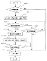
図8は、上記した実施形態及び図7の変形例における車両ドアの解錠作動と発光部材の発光状態を示すフローチャート、図9は車両ドアの施錠作動と発光部材の発光状態を示すフローチャートである。
【0030】
先ず、図8の車両ドアの解錠作動について説明する。ステップS100にて携帯機60を携帯した人が車両ドアに接近したか否かを判断し、携帯機60を認識すると、ステップS101に進んでLED24を点灯する。尚、図7の変形例の場合には、第1LED24Aを点灯する。次に、ステップS102に進んでドアロック解錠の意思を認識されたか否かを判断する。具体的には、人が車両ドアを開ける際に人の手がドアハンドル20の裏側に接触すると、ドアロック解錠の意思が認識されてステップS103に進む。ステップS102でドアロック解錠の意思が認識されない場合には、ステップS107に進み、携帯機60が認識されてから所定時間が経過したか否かを判断する。所定時間が経過していなければ、再びステップS102に進んでドアロック解錠の意思が認識されたか否かを判断する。所定時間が経過していると、後述するステップS106に進む。ステップS102にてドアロック解錠の意思が認識された場合には、ステップS103に進んでドアロック機構11を作動させて車両ドアを解錠する。そして、ステップS104にてLED24が点滅する。尚、図7の変形例の場合には、ステップS104にて第2LED24Bを点灯する。次に、ステップS105でLED24の点滅或いは第2LED24Bの点灯から所定時間が経過したか否かを判断し、所定時間経過した場合にはステップS106に進み、点滅或いは点灯しているLED(LED24、第1LED24A、第2LED24B)を消灯する。このようにして車両ドアの解錠作動が行われる。
【0031】
図9の車両ドアの施錠作動について説明する。先ず、ステップS200にて携帯機60を携帯した人が車室内から車外に移動したか否かを判断する。このような携帯機60の移動を認識すると、ステップS201に進んでLED24を点滅する。尚、図7の変形例の場合には、第2LED24Bを点灯する。次に、ステップS202に進んでドアロック施錠の意思を認識されたか否かを判断する。具体的には、人が車両ドアを閉める際に人の手がドアハンドル20の表面に接触すると、ドアロック施錠の意思が認識されてステップS203に進む。ステップS202でドアロック施錠の意思が認識されない場合には、ステップS207に進み、携帯機60の移動が認識されてから所定時間が経過したか否かを判断する。所定時間が経過していなければ、再びステップS202に進んでドアロック施錠の意思が認識されたか否かを判断する。所定時間が経過していると、後述するステップS206に進む。ステップS202にてドアロック施錠の意思が認識された場合には、ステップS203に進んでドアロック機構11を作動させて車両ドアを施錠する。そして、ステップS204にてLED24を点灯する。尚、図7の変形例の場合には、ステップS204にて第1LED24Aを点灯する。次に、ステップS205でLED24の点灯或いは第1LED24Aの点灯から所定時間が経過したか否かを判断し、所定時間経過した場合にはステップS206に進み、点灯しているLED(LED24、第1LED24A、第2LED24B)を消灯する。このようにして車両ドアの施錠作動が行われる。
【0032】
上述したシステム1によると、人が車両ドアを開閉作動するに際して、人によるドアハンドル20の操作が行われた直後にドアハンドル20に内蔵された発光部材24が発光することで、車両ドアの解錠状態及び車両ドアの施錠状態の報知が行われる。ドアハンドル20の操作時には、一般的に人の視線はドアハンドル20に向いているので、ドアハンドル20に内蔵された発光部材24の発光はドアハンドル20の操作時に人の目につき易い。したがって、車両ドアの解錠及び施錠を確実に認識できる。
【0033】
以上、本発明の実施の形態について説明したが、本発明は上述した実施の形態に限定されるものではなく、例えば、車両ドアの解錠に際して、図8のステップS107を、所定時間が経過したか否かを判断するのではなく、携帯機60が車両ドアから離間して携帯機60が認識されなくなったか否かを判断するようにしてもよい。また、図9に関して、ステップS200とステップS202の処理を入れ替え、人が車両ドアを閉めてドアハンドル20が操作されることを先に認識し、LEDを点灯或いは点滅させた後に携帯機60の位置を認識してから車両ドアを施錠するようにしてもよい。更に、図8及び図9におけるLED24の点灯と点滅を入れ替えてもよい。また、図8のステップS105とS107、図9のステップS205とS207の所定時間は、同一の時間であっても異なる時間であってもどちらでもよい。
【0034】
【発明の効果】
本発明によると、ドアハンドルに内蔵された発光部材がドアハンドルの操作の前後に発光することとなり、これら発光に対しての人の視認度は比較的高いため、車両ドアの状態が確実に人に報知される。
【図面の簡単な説明】
【図1】本発明の実施形態の車両用ドア開閉装置をキーレスエントリーシステム(スマートエントリーシステム)に適用した場合のシステムブロック図である。
【図2】図1のシステムにおける携帯機のブロック図である。
【図3】図1のドアハンドル及び第1オシレータの詳細ブロック図である。
【図4】ドアハンドルの断面概略図である。
【図5】ドアハンドルにおける発光部材を含む箇所の断面図である。
【図6】発光部材のドアハンドルへの取り付けを示す斜視図である。
【図7】本実施形態における発光部材の変形例である。
【図8】車両ドアの解錠作動と発光部材の発光状態を示すフローチャートである。
【図9】車両ドアの施錠作動と発光部材の発光状態を示すフローチャートである。
【符号の説明】
1 キーレスエントリーシステム(ドア開閉装置)
11 ドアロック機構
12 ドアECU(制御機構)
20 ドアハンドル
22 ドア解錠用センサ電極(センサ電極)
23 ドア施錠用センサ電極(センサ電極)
24、24A、24B 発光部材
44 システムECU(制御機構)
60 携帯機[0001]
BACKGROUND OF THE INVENTION
The present invention relates to a vehicle door opening / closing device that detects the approach of a person to a vehicle, unlocks the vehicle door when the vehicle door is opened, and locks the vehicle door when the vehicle door is closed.
[0002]
[Prior art]
Conventionally, a person (usually a driver) carries a portable device called a remote controller that opens and closes a vehicle door in the vehicle, and automatically detects the state in which the person approaches or moves away from the vehicle door. 2. Description of the Related Art A vehicle door opening / closing device that locks or unlocks a door is known. Such a locking system (smart entry system) in a vehicle door opening and closing device is intended to improve convenience and safety, and is described in Japanese Patent Application Laid-Open No. 2000-160897.
[0003]
In the above prior art, it is disclosed that the vehicle door is automatically unlocked / locked, but there is no disclosure about notifying the person of the unlocked / locked state of the vehicle door. . It may be very difficult for a person to confirm whether the vehicle door is actually locked without notifying the state of the vehicle door. Therefore, it is necessary to notify a person by some means that the vehicle door is locked or unlocked.
[0004]
In JP-A-2000-45593, when unlocking / locking a vehicle door, a light control signal is output by determining the light emission quantity or light quality of the interior lighting, headlamp, tail lamp, etc. according to the brightness around the vehicle. In other words, it is disclosed that a sound control signal is output by determining the amount of sound or sound quality of a buzzer corresponding to the brightness around the vehicle. Specifically, since it may be difficult to recognize only by light emission when the surroundings are bright like daytime, the buzzer is used to suppress the light emission, and when the surroundings are dark like dusk or night The sound is suppressed and the light emission is also performed. According to this, it is possible to easily notify the person of the unlocked or locked state of the vehicle door.
[0005]
[Problems to be solved by the invention]
However, in the notification of the technique disclosed in Japanese Patent Laid-Open No. 2000-45593 described above, the interior lighting, the head lamp, and the tail lamp are provided at a location separated from the door handle operated when a person opens and closes the vehicle door. . Therefore, in a vehicle door opening / closing device that is automatically unlocked or locked by a person operating a door handle, it is not always possible for a person to recognize the state of the vehicle door from the viewpoint of human visibility. There is no problem.
[0006]
Therefore, in order to solve the above-described problem, the present invention provides a vehicle door opening / closing device capable of providing notification so that a person can surely recognize the unlocked / locked state of the vehicle door. Let it be an issue.
[0007]
[Means for Solving the Problems]
In order to solve the above problems, the invention of
[0008]
Since the control mechanism in
[0009]
DETAILED DESCRIPTION OF THE INVENTION
Hereinafter, embodiments of the present invention will be described with reference to the drawings. FIG. 1 is a system block diagram on the vehicle side when the vehicle door opening and closing device of the present invention is applied to a keyless entry system (also called a smart entry system) 1 (door opening and closing device) of a vehicle. This
[0010]
The configuration of the
[0011]
In the vehicle, a second transmission antenna 41 that performs communication in the vehicle, a
[0012]
In this
[0013]
Further, in this
[0014]
The
[0015]
The ID information signal output from the
[0016]
FIG. 2 is a block diagram of the
[0017]
A request signal (external request signal) from the vehicle received by the receiving antenna 64 of the
[0018]
The operation of the
[0019]
In the door unlocking mode, detection by the door unlocking
[0020]
When a person grasps the door handle 20 from this state, a sense signal is transmitted from the door unlocking
[0021]
Next, the operation of the
[0022]
In the door locking mode, detection by the door locking
[0023]
When a person touches the door handle 20 from this state, a lock signal is transmitted from the door locking
[0024]
Next, referring to FIGS. 3 and 4, the
[0025]
The
[0026]
The
[0027]
When a person opens the vehicle door, the person's hand grips the
[0028]
The
[0029]
FIG. 8 is a flowchart showing the unlocking operation of the vehicle door and the light emitting state of the light emitting member in the above embodiment and the modification of FIG. 7, and FIG. 9 is a flowchart showing the locking operation of the vehicle door and the light emitting state of the light emitting member. .
[0030]
First, the unlocking operation of the vehicle door in FIG. 8 will be described. In step S100, it is determined whether the person carrying the
[0031]
The locking operation of the vehicle door in FIG. 9 will be described. First, in step S200, it is determined whether or not the person carrying the
[0032]
According to the
[0033]
Although the embodiment of the present invention has been described above, the present invention is not limited to the above-described embodiment. For example, when unlocking the vehicle door, step S107 in FIG. Instead of determining whether or not the
[0034]
【The invention's effect】
According to the present invention , De Light-emitting member built into the handle Before and after door handle operation Light emission Will emit these light The visibility of people against is relatively high Because The person is surely notified of the state of the vehicle door.
[Brief description of the drawings]
FIG. 1 is a system block diagram when a vehicle door opening / closing device according to an embodiment of the present invention is applied to a keyless entry system (smart entry system).
FIG. 2 is a block diagram of a portable device in the system of FIG.
FIG. 3 is a detailed block diagram of the door handle and the first oscillator of FIG. 1;
FIG. 4 is a schematic sectional view of a door handle.
FIG. 5 is a cross-sectional view of a portion including a light emitting member in a door handle.
FIG. 6 is a perspective view showing attachment of a light emitting member to a door handle.
FIG. 7 is a modification of the light emitting member in the present embodiment.
FIG. 8 is a flowchart showing the unlocking operation of the vehicle door and the light emitting state of the light emitting member.
FIG. 9 is a flowchart showing the locking operation of the vehicle door and the light emission state of the light emitting member.
[Explanation of symbols]
1 Keyless entry system (door opener)
11 Door lock mechanism
12 Door ECU (control mechanism)
20 Door handle
22 Sensor electrode for unlocking door (sensor electrode)
23 Sensor electrode for door locking (sensor electrode)
24, 24A, 24B Light emitting member
44 System ECU (control mechanism)
60 Mobile devices
Claims (9)
車両ドアの施錠及び解錠を行うドアロック機構と、
車外に向けて車外リクエスト信号を送信する第1送信アンテナと、
車内に向けて車内リクエスト信号を送信する第2送信アンテナと、
前記ドアハンドルの操作に基づいて車両ドアの開閉意思を検出する検出手段と、
携帯機から車外リクエスト信号に基づくID情報信号を受信した場合に、携帯機が車両に近づいたとしてドア解錠モードに移行し、このドア解錠モード中に前記検出手段が車両ドアの解錠意思を検出したときに前記ドアロック機構を解錠させる一方、携帯機から車内リクエスト信号に基づくID情報信号の受信が途絶えた場合に、前記携帯機が車内から車外へ出たとしてドア施錠モードに移行し、該ドア施錠モード中に前記検出手段が車両ドアの施錠意思を検出したときに前記ドアロック機構を施錠させる制御機構と、
を備える車両用ドア開閉装置であって、
前記ドアハンドルは、該ドアハンドルの外部から確認可能な発光部材を内蔵し、
前記制御機構は、前記ドア開錠モードおよび前記ドア施錠モードへの移行時に前記発光部材を発光させるとともに、前記ドアロック機構の作動に連動して前記発光部材の発光状態を変化させることを特徴とする車両用ドア開閉装置。A door handle for opening and closing the vehicle door;
A door lock mechanism for locking and unlocking the vehicle door;
A first transmitting antenna for transmitting a request signal outside the vehicle,
A second transmitting antenna for transmitting an in-vehicle request signal toward the inside of the vehicle;
Detecting means for detecting an intention to open and close the vehicle door based on an operation of the door handle;
When the ID information signal based on the request signal outside the vehicle is received from the portable device, the portable device moves to the door unlocking mode because the vehicle approaches the vehicle, and the detection means intends to unlock the vehicle door during the door unlocking mode. The door lock mechanism is unlocked when an ID is detected, and when the reception of the ID information signal based on the in-vehicle request signal from the portable device is interrupted, the portable device shifts to the door locking mode on the assumption that the portable device has exited the vehicle A control mechanism for locking the door lock mechanism when the detection means detects the intention of locking the vehicle door during the door locking mode;
A vehicle door opening and closing device comprising:
The door handle incorporates a light emitting member that can be confirmed from the outside of the door handle,
The control mechanism causes the light emitting member to emit light at the time of transition to the door unlocking mode and the door locking mode, and changes the light emitting state of the light emitting member in conjunction with the operation of the door lock mechanism. A vehicle door opening and closing device.
前記制御機構は、前記センサ電極が人と前記ドアハンドルとの接触を検出することにより車両ドアの解錠意思又は施錠意思を認識することを特徴とする、請求項1に記載の車両用ドア開閉装置。The detection means is a sensor electrode that is provided on the door handle and detects contact between a person and the door handle,
2. The vehicle door opening and closing according to claim 1, wherein the control mechanism recognizes an intention to unlock or lock the vehicle door by detecting contact between the sensor electrode and a person and the door handle. apparatus.
前記制御機構は、前記操作スイッチがオン操作されることにより車両ドアの解錠意思又は施錠意思を認識することを特徴とする、請求項1に記載の車両用ドア開閉装置。The detection means is an operation switch that is provided on the door handle and can be turned on.
2. The vehicle door opening and closing device according to claim 1, wherein the control mechanism recognizes an intention to unlock or lock the vehicle door when the operation switch is turned on.
Priority Applications (3)
| Application Number | Priority Date | Filing Date | Title |
|---|---|---|---|
| JP2002183194A JP3901034B2 (en) | 2002-06-24 | 2002-06-24 | Vehicle door opening and closing device |
| DE2003128332 DE10328332B4 (en) | 2002-06-24 | 2003-06-24 | Door opening / closing device for a vehicle and method for detecting an opening / closing operation of a vehicle door |
| US10/601,874 US7049940B2 (en) | 2002-06-24 | 2003-06-24 | Door opening/closing device for a vehicle and a method of recognizing an opening/closing operation of a vehicle door |
Applications Claiming Priority (1)
| Application Number | Priority Date | Filing Date | Title |
|---|---|---|---|
| JP2002183194A JP3901034B2 (en) | 2002-06-24 | 2002-06-24 | Vehicle door opening and closing device |
Publications (2)
| Publication Number | Publication Date |
|---|---|
| JP2004027559A JP2004027559A (en) | 2004-01-29 |
| JP3901034B2 true JP3901034B2 (en) | 2007-04-04 |
Family
ID=30437025
Family Applications (1)
| Application Number | Title | Priority Date | Filing Date |
|---|---|---|---|
| JP2002183194A Expired - Fee Related JP3901034B2 (en) | 2002-06-24 | 2002-06-24 | Vehicle door opening and closing device |
Country Status (3)
| Country | Link |
|---|---|
| US (1) | US7049940B2 (en) |
| JP (1) | JP3901034B2 (en) |
| DE (1) | DE10328332B4 (en) |
Cited By (2)
| Publication number | Priority date | Publication date | Assignee | Title |
|---|---|---|---|---|
| JP2015098707A (en) * | 2013-11-19 | 2015-05-28 | 株式会社小糸製作所 | Door handle |
| JP2016003536A (en) * | 2014-06-19 | 2016-01-12 | 美和ロック株式会社 | Electric lock system |
Families Citing this family (53)
| Publication number | Priority date | Publication date | Assignee | Title |
|---|---|---|---|---|
| US7251615B2 (en) * | 2002-06-07 | 2007-07-31 | Oracle International Corporation | Markdown management |
| JP4142378B2 (en) * | 2002-09-19 | 2008-09-03 | 株式会社アルファ | Vehicle door locking / unlocking control system |
| US7205884B2 (en) * | 2002-12-19 | 2007-04-17 | Denso Corporation | Vehicle electronic key system |
| DE10300573A1 (en) * | 2003-01-10 | 2004-07-22 | Daimlerchrysler Ag | Device for locking and unlocking a vehicle door |
| JP2004244990A (en) * | 2003-02-17 | 2004-09-02 | Kojima Press Co Ltd | Outside handle for car and outside handle device for car |
| JP2005163295A (en) * | 2003-11-28 | 2005-06-23 | Alpha Corp | Door opening/closing device |
| JP4041090B2 (en) * | 2004-04-06 | 2008-01-30 | 本田技研工業株式会社 | Remote locking / unlocking control device for vehicle |
| DE102004019571B4 (en) * | 2004-04-22 | 2006-02-23 | Huf Hülsbeck & Fürst Gmbh & Co. Kg | Device for actuating an electrical or mechanical closing device on a door and / or a flap of a vehicle |
| JP4240307B2 (en) | 2004-06-22 | 2009-03-18 | アイシン精機株式会社 | Vehicle door opening and closing device |
| JP4257601B2 (en) * | 2004-06-24 | 2009-04-22 | アイシン精機株式会社 | Vehicle door opening and closing device |
| JP4428388B2 (en) * | 2004-09-28 | 2010-03-10 | アイシン精機株式会社 | Antenna device and door handle device |
| JP4479573B2 (en) * | 2005-04-13 | 2010-06-09 | トヨタ自動車株式会社 | Vehicle anti-theft device |
| DE102005020668B4 (en) * | 2005-04-14 | 2007-12-06 | Wolfgang Nitzsche | Method and device for condition control of a locking system, in particular a motor vehicle locking system |
| TWM276736U (en) * | 2005-06-10 | 2005-10-01 | Qa Ma Internat Co Ltd | Alert indicator of vehicular door handles |
| GB2429747A (en) * | 2005-09-05 | 2007-03-07 | Nissan Technical Ct Europ Ltd | Door handle assembly with illuminated status indication |
| DE202005017541U1 (en) * | 2005-11-08 | 2007-03-22 | BROSE SCHLIEßSYSTEME GMBH & CO. KG | Motor vehicle lock e.g. door lock, arrangement, has control unit accessing directly on sensor signals of latch sensor and/or ratchet sensor and providing input signal for other control unit that indirectly accesses sensor signals |
| US8427276B2 (en) * | 2006-02-24 | 2013-04-23 | Denso International America, Inc. | Apparatus for automatically initiating sequence of vehicle functions |
| US8077011B2 (en) * | 2006-02-24 | 2011-12-13 | Denso International America, Inc. | Apparatus for automatically initiating sequence of vehicle functions |
| FR2901392B1 (en) * | 2006-05-18 | 2008-09-05 | Siemens Vdo Automotive Sas | DEVICE FOR DETECTING AN EVENT IN A VEHICLE OR IN THE VEHICLE ENVIRONMENT |
| US20080088426A1 (en) * | 2006-10-13 | 2008-04-17 | Blair Lima | Baby chime |
| DE102007002700A1 (en) * | 2007-01-18 | 2008-07-24 | Daimler Ag | Motor vehicle for use with vehicle door, which locks door opening, has opening device arranged in area of door gap between vehicle door and corresponding door opening |
| US8333492B2 (en) | 2007-05-03 | 2012-12-18 | Donnelly Corporation | Illumination module for a vehicle |
| US8305090B2 (en) | 2007-11-30 | 2012-11-06 | Toyota Jidosha Kabushiki Kaisha | Capacitance touch sensing device and door locking device |
| JP2009143455A (en) * | 2007-12-14 | 2009-07-02 | Fujitsu Ten Ltd | Vehicle control device and vehicle control method |
| JP5502284B2 (en) * | 2008-03-25 | 2014-05-28 | 株式会社東海理化電機製作所 | Electronic key system |
| JP5324816B2 (en) * | 2008-05-08 | 2013-10-23 | アイシン精機株式会社 | Vehicle door handle |
| JP5109172B2 (en) * | 2008-05-28 | 2012-12-26 | スミダコーポレーション株式会社 | Transmitting antenna device and door handle in which transmitting antenna device is accommodated |
| US20100007463A1 (en) * | 2008-07-09 | 2010-01-14 | Magna Mirrors Of America, Inc. | Vehicle handle with control circuitry |
| US7916021B2 (en) * | 2008-08-13 | 2011-03-29 | Honda Motor Co., Ltd. | Smart entry system and method |
| KR20100053864A (en) * | 2008-11-13 | 2010-05-24 | 현대자동차주식회사 | Handle structure of door outside |
| JP2010209609A (en) * | 2009-03-11 | 2010-09-24 | Omron Corp | Door handle |
| IT1396932B1 (en) * | 2009-11-20 | 2012-12-20 | Valeo Spa | COMMAND DEVICE FOR RELEASING THE HANDLE OF A VEHICLE WITH AN EXTERNAL COMMAND ORGAN. |
| US8764256B2 (en) | 2010-10-01 | 2014-07-01 | Magna Mirrors Of America, Inc. | Vehicle exterior mirror system with light module |
| US10576896B2 (en) | 2010-10-01 | 2020-03-03 | Magna Mirrors Of America, Inc. | Vehicle exterior mirror system with light module |
| US8579481B2 (en) | 2010-10-28 | 2013-11-12 | AISIN Technical Center of America, Inc. | Lit door handle for a vehicle |
| DE102011117978A1 (en) * | 2010-11-11 | 2012-05-16 | Marquardt Gmbh | Locking system, in particular for a motor vehicle |
| JP6034006B2 (en) * | 2011-08-08 | 2016-11-30 | 株式会社アルファ | Door operation handle |
| KR101189562B1 (en) | 2012-01-03 | 2012-10-11 | 주식회사 웰리스 | Appratus for alram of door locking status using vibro speaker |
| DE102012105117A1 (en) * | 2012-06-13 | 2013-12-19 | Huf Hülsbeck & Fürst Gmbh & Co. Kg | Approach detecting device |
| JP5974693B2 (en) * | 2012-07-10 | 2016-08-23 | アイシン精機株式会社 | Antenna drive device |
| US9227558B2 (en) * | 2013-01-14 | 2016-01-05 | GM Global Technology Operations LLC | Vehicle exterior door handle lighting |
| JP2015085900A (en) * | 2013-11-01 | 2015-05-07 | トヨタ自動車九州株式会社 | Door knob light emitting device of automobile |
| JP6115731B2 (en) * | 2014-02-10 | 2017-04-19 | 株式会社デンソー | Vehicle control device |
| FR3025824B1 (en) | 2014-09-11 | 2016-09-16 | Continental Automotive France | METHOD FOR DETECTING ACTUATION OF A DOOR HANDLE OF A MOTOR VEHICLE |
| DE102014117909B4 (en) * | 2014-12-04 | 2022-01-27 | Lisa Dräxlmaier GmbH | Grip recess lighting for door panels |
| DE102015200042B4 (en) | 2015-01-06 | 2018-09-06 | Volkswagen Aktiengesellschaft | Bidirectional communication in the vehicle |
| DE102015013192A1 (en) | 2015-10-10 | 2016-04-21 | Daimler Ag | Method for locking and unlocking at least one vehicle door of a vehicle |
| JP6698160B2 (en) * | 2016-07-08 | 2020-05-27 | 本田技研工業株式会社 | Door structure |
| DE102016212527B4 (en) | 2016-07-08 | 2019-08-08 | Magna Mirrors Holding Gmbh | Blink unit for an exterior mirror |
| JP6836054B2 (en) * | 2016-09-30 | 2021-02-24 | テイ・エス テック株式会社 | Door lock device and door |
| US10985756B2 (en) * | 2018-05-14 | 2021-04-20 | GM Global Technology Operations LLC | Thin film door switch with integrated lighting |
| JP7216305B2 (en) * | 2021-02-03 | 2023-02-01 | テイ・エス テック株式会社 | Door lock device and door |
| DE102022104045A1 (en) * | 2022-02-21 | 2023-08-24 | Bayerische Motoren Werke Aktiengesellschaft | Vehicle door for a motor vehicle and method for operating such a vehicle door |
Family Cites Families (25)
| Publication number | Priority date | Publication date | Assignee | Title |
|---|---|---|---|---|
| US4929936A (en) * | 1988-03-21 | 1990-05-29 | Home Security Systems, Inc. | LED illuminated sign |
| JPH01275239A (en) * | 1988-04-28 | 1989-11-02 | Mazda Motor Corp | Door lock control device for vehicle |
| JPH0741643Y2 (en) * | 1988-08-30 | 1995-09-27 | 株式会社アルファ | Electromagnetic wave detection display device for automobile |
| JPH0399158U (en) * | 1990-01-31 | 1991-10-16 | ||
| JPH0581473U (en) * | 1992-03-31 | 1993-11-05 | ナイルス部品株式会社 | Door lock monitor device |
| JPH0791121A (en) * | 1993-09-27 | 1995-04-04 | Matsushita Electric Works Ltd | Secret electric lock operator |
| JP3193587B2 (en) * | 1995-05-26 | 2001-07-30 | 関東自動車工業株式会社 | Lighting device for automobile door handle |
| JPH0932378A (en) * | 1995-07-21 | 1997-02-04 | Omron Corp | Locking device and locking system |
| DE19617038C2 (en) * | 1996-04-27 | 2000-11-30 | Huf Huelsbeck & Fuerst Gmbh | Locking system, in particular for motor vehicles |
| JPH11165585A (en) * | 1997-12-05 | 1999-06-22 | Toyoda Gosei Co Ltd | Out-vehicle lighting system |
| US6164805A (en) * | 1998-04-20 | 2000-12-26 | Federal-Mogul World Wide, Inc. | Illuminated door handle for a vehicle |
| US6135621A (en) * | 1998-02-13 | 2000-10-24 | Bach; Kent | Illuminated handle |
| DE19822733C2 (en) * | 1998-05-20 | 2001-05-10 | Bayerische Motoren Werke Ag | Device for illuminating the apron on the side of a vehicle |
| JP2000045593A (en) * | 1998-07-24 | 2000-02-15 | Toyota Motor Corp | Equipment-operation receiver for car |
| JP3648396B2 (en) | 1998-12-02 | 2005-05-18 | トヨタ自動車株式会社 | Vehicle door handle |
| DE19912319C1 (en) * | 1999-03-19 | 2000-10-12 | Daimler Chrysler Ag | Electronic locking system, in particular vehicle locking system |
| FR2796412B1 (en) * | 1999-07-16 | 2001-09-07 | Valeo Securite Habitacle | MOTOR VEHICLE OPENING HANDLE COMPRISING RELEASABLE MEANS CONTROLS OF LOCK OPERATION |
| EP1083285A1 (en) * | 1999-09-07 | 2001-03-14 | Robert Bosch Gmbh | Vehicle door locking system |
| FR2800782B1 (en) * | 1999-11-10 | 2001-12-21 | Valeo Securite Habitacle | MOTOR VEHICLE EQUIPPED WITH A HANDS-FREE ACCESS AND / OR STARTING SYSTEM |
| JP2001227218A (en) * | 2000-02-21 | 2001-08-24 | Omron Corp | Control device |
| JP2001336321A (en) * | 2000-05-31 | 2001-12-07 | Omron Corp | Control device |
| US6349450B1 (en) * | 2000-06-20 | 2002-02-26 | Donnelly Corporation | Vehicle door handle |
| JP2002106214A (en) * | 2000-09-28 | 2002-04-10 | Calsonic Kansei Corp | Door opening motion detecting method and device for vehicle |
| DE10060780A1 (en) * | 2000-12-07 | 2002-06-13 | Bayerische Motoren Werke Ag | Door handle for use on road vehicle incorporates steady or blinking lamp underneath transparent layer on outside of handle |
| DE10121046A1 (en) * | 2001-04-28 | 2002-11-07 | Huf Huelsbeck & Fuerst Gmbh | External actuation for vehicle locks on doors, flaps or the like. |
-
2002
- 2002-06-24 JP JP2002183194A patent/JP3901034B2/en not_active Expired - Fee Related
-
2003
- 2003-06-24 DE DE2003128332 patent/DE10328332B4/en not_active Expired - Fee Related
- 2003-06-24 US US10/601,874 patent/US7049940B2/en not_active Expired - Fee Related
Cited By (3)
| Publication number | Priority date | Publication date | Assignee | Title |
|---|---|---|---|---|
| JP2015098707A (en) * | 2013-11-19 | 2015-05-28 | 株式会社小糸製作所 | Door handle |
| US10668851B2 (en) | 2013-11-19 | 2020-06-02 | Koito Manufacturing Co., Ltd. | Door handle |
| JP2016003536A (en) * | 2014-06-19 | 2016-01-12 | 美和ロック株式会社 | Electric lock system |
Also Published As
| Publication number | Publication date |
|---|---|
| DE10328332A1 (en) | 2004-02-12 |
| JP2004027559A (en) | 2004-01-29 |
| US20040075531A1 (en) | 2004-04-22 |
| DE10328332B4 (en) | 2012-11-15 |
| US7049940B2 (en) | 2006-05-23 |
Similar Documents
| Publication | Publication Date | Title |
|---|---|---|
| JP3901034B2 (en) | Vehicle door opening and closing device | |
| US10099656B2 (en) | Swipe and tap verification for entry system using swipe and tap touch switch | |
| JP4257601B2 (en) | Vehicle door opening and closing device | |
| US8149083B2 (en) | Vehicle door opening/closing apparatus and method for controlling a vehicle door to open/close | |
| US7098791B2 (en) | Security system and portable device usable therein | |
| JP4063645B2 (en) | Vehicle drive control device | |
| EP1452672A1 (en) | Door opening/closing device for vehicle | |
| WO2005124066A1 (en) | Opening and closing apparatus for vehicle door | |
| US20150353033A1 (en) | Hybrid entry system | |
| JP2004175252A (en) | Lighting control device for vehicle | |
| JP2005133529A (en) | Actuating device for vehicular opening/closing body | |
| JP4742979B2 (en) | Keyless entry system | |
| JP2009179998A (en) | On-vehicle device control system | |
| JP2002047839A (en) | Control device | |
| JP5260401B2 (en) | Locking / unlocking operation detection device | |
| JP4022913B2 (en) | Wireless device | |
| JP2004060191A (en) | Door handle for car | |
| US20100052848A1 (en) | Remote vehicle operating system | |
| US20080211642A1 (en) | Antitheft device for vehicle | |
| JP4084170B2 (en) | Vehicle drive system operating device and vehicle drive control system | |
| JP3814161B2 (en) | Keyless entry device | |
| US7710244B2 (en) | Remote engine starting system and method | |
| JP5480418B2 (en) | Locking / unlocking operation detection device | |
| JP4091406B2 (en) | Vehicle key storage device | |
| JP2000145228A (en) | On-vehicle apparatus remote control device |
Legal Events
| Date | Code | Title | Description |
|---|---|---|---|
| RD03 | Notification of appointment of power of attorney |
Free format text: JAPANESE INTERMEDIATE CODE: A7423 Effective date: 20050609 |
|
| A977 | Report on retrieval |
Free format text: JAPANESE INTERMEDIATE CODE: A971007 Effective date: 20051101 |
|
| A131 | Notification of reasons for refusal |
Free format text: JAPANESE INTERMEDIATE CODE: A131 Effective date: 20060411 |
|
| A521 | Written amendment |
Free format text: JAPANESE INTERMEDIATE CODE: A523 Effective date: 20060612 |
|
| A131 | Notification of reasons for refusal |
Free format text: JAPANESE INTERMEDIATE CODE: A131 Effective date: 20060905 |
|
| A521 | Written amendment |
Free format text: JAPANESE INTERMEDIATE CODE: A523 Effective date: 20061031 |
|
| TRDD | Decision of grant or rejection written | ||
| A01 | Written decision to grant a patent or to grant a registration (utility model) |
Free format text: JAPANESE INTERMEDIATE CODE: A01 Effective date: 20061212 |
|
| A61 | First payment of annual fees (during grant procedure) |
Free format text: JAPANESE INTERMEDIATE CODE: A61 Effective date: 20061225 |
|
| R151 | Written notification of patent or utility model registration |
Ref document number: 3901034 Country of ref document: JP Free format text: JAPANESE INTERMEDIATE CODE: R151 |
|
| FPAY | Renewal fee payment (event date is renewal date of database) |
Free format text: PAYMENT UNTIL: 20100112 Year of fee payment: 3 |
|
| FPAY | Renewal fee payment (event date is renewal date of database) |
Free format text: PAYMENT UNTIL: 20110112 Year of fee payment: 4 |
|
| FPAY | Renewal fee payment (event date is renewal date of database) |
Free format text: PAYMENT UNTIL: 20110112 Year of fee payment: 4 |
|
| FPAY | Renewal fee payment (event date is renewal date of database) |
Free format text: PAYMENT UNTIL: 20120112 Year of fee payment: 5 |
|
| FPAY | Renewal fee payment (event date is renewal date of database) |
Free format text: PAYMENT UNTIL: 20130112 Year of fee payment: 6 |
|
| FPAY | Renewal fee payment (event date is renewal date of database) |
Free format text: PAYMENT UNTIL: 20130112 Year of fee payment: 6 |
|
| FPAY | Renewal fee payment (event date is renewal date of database) |
Free format text: PAYMENT UNTIL: 20140112 Year of fee payment: 7 |
|
| LAPS | Cancellation because of no payment of annual fees |