JP3898987B2 - Image forming apparatus, image transfer control method used in the apparatus, program causing computer to execute the method, and computer-readable recording medium storing the program - Google Patents
Image forming apparatus, image transfer control method used in the apparatus, program causing computer to execute the method, and computer-readable recording medium storing the program Download PDFInfo
- Publication number
- JP3898987B2 JP3898987B2 JP2002207172A JP2002207172A JP3898987B2 JP 3898987 B2 JP3898987 B2 JP 3898987B2 JP 2002207172 A JP2002207172 A JP 2002207172A JP 2002207172 A JP2002207172 A JP 2002207172A JP 3898987 B2 JP3898987 B2 JP 3898987B2
- Authority
- JP
- Japan
- Prior art keywords
- image
- transfer
- image data
- resource
- unit
- Prior art date
- Legal status (The legal status is an assumption and is not a legal conclusion. Google has not performed a legal analysis and makes no representation as to the accuracy of the status listed.)
- Expired - Fee Related
Links
Images


Classifications
-
- H—ELECTRICITY
- H04—ELECTRIC COMMUNICATION TECHNIQUE
- H04N—PICTORIAL COMMUNICATION, e.g. TELEVISION
- H04N1/00—Scanning, transmission or reproduction of documents or the like, e.g. facsimile transmission; Details thereof
- H04N1/32—Circuits or arrangements for control or supervision between transmitter and receiver or between image input and image output device, e.g. between a still-image camera and its memory or between a still-image camera and a printer device
- H04N1/32358—Circuits or arrangements for control or supervision between transmitter and receiver or between image input and image output device, e.g. between a still-image camera and its memory or between a still-image camera and a printer device using picture signal storage, e.g. at transmitter
- H04N1/32443—Circuits or arrangements for control or supervision between transmitter and receiver or between image input and image output device, e.g. between a still-image camera and its memory or between a still-image camera and a printer device using picture signal storage, e.g. at transmitter with asynchronous operation of the image input and output devices connected to the memory
-
- H—ELECTRICITY
- H04—ELECTRIC COMMUNICATION TECHNIQUE
- H04N—PICTORIAL COMMUNICATION, e.g. TELEVISION
- H04N1/00—Scanning, transmission or reproduction of documents or the like, e.g. facsimile transmission; Details thereof
- H04N1/00912—Arrangements for controlling a still picture apparatus or components thereof not otherwise provided for
- H04N1/00915—Assigning priority to, or interrupting, a particular operation
-
- H—ELECTRICITY
- H04—ELECTRIC COMMUNICATION TECHNIQUE
- H04N—PICTORIAL COMMUNICATION, e.g. TELEVISION
- H04N1/00—Scanning, transmission or reproduction of documents or the like, e.g. facsimile transmission; Details thereof
- H04N1/00912—Arrangements for controlling a still picture apparatus or components thereof not otherwise provided for
- H04N1/00954—Scheduling operations or managing resources
-
- H—ELECTRICITY
- H04—ELECTRIC COMMUNICATION TECHNIQUE
- H04N—PICTORIAL COMMUNICATION, e.g. TELEVISION
- H04N1/00—Scanning, transmission or reproduction of documents or the like, e.g. facsimile transmission; Details thereof
- H04N1/32—Circuits or arrangements for control or supervision between transmitter and receiver or between image input and image output device, e.g. between a still-image camera and its memory or between a still-image camera and a printer device
- H04N1/32358—Circuits or arrangements for control or supervision between transmitter and receiver or between image input and image output device, e.g. between a still-image camera and its memory or between a still-image camera and a printer device using picture signal storage, e.g. at transmitter
-
- H—ELECTRICITY
- H04—ELECTRIC COMMUNICATION TECHNIQUE
- H04N—PICTORIAL COMMUNICATION, e.g. TELEVISION
- H04N1/00—Scanning, transmission or reproduction of documents or the like, e.g. facsimile transmission; Details thereof
- H04N1/32—Circuits or arrangements for control or supervision between transmitter and receiver or between image input and image output device, e.g. between a still-image camera and its memory or between a still-image camera and a printer device
- H04N1/32561—Circuits or arrangements for control or supervision between transmitter and receiver or between image input and image output device, e.g. between a still-image camera and its memory or between a still-image camera and a printer device using a programmed control device, e.g. a microprocessor
-
- H—ELECTRICITY
- H04—ELECTRIC COMMUNICATION TECHNIQUE
- H04N—PICTORIAL COMMUNICATION, e.g. TELEVISION
- H04N2201/00—Indexing scheme relating to scanning, transmission or reproduction of documents or the like, and to details thereof
- H04N2201/0077—Types of the still picture apparatus
- H04N2201/0081—Image reader
-
- H—ELECTRICITY
- H04—ELECTRIC COMMUNICATION TECHNIQUE
- H04N—PICTORIAL COMMUNICATION, e.g. TELEVISION
- H04N2201/00—Indexing scheme relating to scanning, transmission or reproduction of documents or the like, and to details thereof
- H04N2201/0077—Types of the still picture apparatus
- H04N2201/0082—Image hardcopy reproducer
-
- H—ELECTRICITY
- H04—ELECTRIC COMMUNICATION TECHNIQUE
- H04N—PICTORIAL COMMUNICATION, e.g. TELEVISION
- H04N2201/00—Indexing scheme relating to scanning, transmission or reproduction of documents or the like, and to details thereof
- H04N2201/32—Circuits or arrangements for control or supervision between transmitter and receiver or between image input and image output device, e.g. between a still-image camera and its memory or between a still-image camera and a printer device
- H04N2201/3285—Circuits or arrangements for control or supervision between transmitter and receiver or between image input and image output device, e.g. between a still-image camera and its memory or between a still-image camera and a printer device using picture signal storage, e.g. at transmitter
- H04N2201/3287—Storage of at least one complete document page or image frame
-
- H—ELECTRICITY
- H04—ELECTRIC COMMUNICATION TECHNIQUE
- H04N—PICTORIAL COMMUNICATION, e.g. TELEVISION
- H04N2201/00—Indexing scheme relating to scanning, transmission or reproduction of documents or the like, and to details thereof
- H04N2201/32—Circuits or arrangements for control or supervision between transmitter and receiver or between image input and image output device, e.g. between a still-image camera and its memory or between a still-image camera and a printer device
- H04N2201/3285—Circuits or arrangements for control or supervision between transmitter and receiver or between image input and image output device, e.g. between a still-image camera and its memory or between a still-image camera and a printer device using picture signal storage, e.g. at transmitter
- H04N2201/3288—Storage of two or more complete document pages or image frames
Landscapes
- Engineering & Computer Science (AREA)
- Multimedia (AREA)
- Signal Processing (AREA)
- Computer Hardware Design (AREA)
- Microelectronics & Electronic Packaging (AREA)
- General Engineering & Computer Science (AREA)
- Facsimiles In General (AREA)
- Record Information Processing For Printing (AREA)
- Storing Facsimile Image Data (AREA)
- Accessory Devices And Overall Control Thereof (AREA)
- Signal Processing For Digital Recording And Reproducing (AREA)
Description
【0001】
【発明の属する技術分野】
この発明は、デジタル複写機、ファクシミリ、プリンタ、スキャナーなどの入力された画像を記憶し、記憶した画像を印刷出力する機能を有する画像形成装置において、より詳しくは、ハードディスクなどの2次記憶装置に画像を蓄積し印刷用の半導体メモリーへ画像データを転送して印刷をおこなう画像形成装置、該装置に用いられる画像転送制御方法、およびその方法をコンピュータに実行させるプログラム、並びにそのプログラムを記録したコンピュータ読み取り可能な記録媒体に関する。
【従来の技術】
近年の画像形成装置は、印刷用の画像を画像処理する機能を有しており、このような装置は、画像処理のための画像データをハードディスク装置(HDD)などの2次記憶装置に蓄積するようになっている。印刷時には、2次記憶装置から半導体メモリーに画像を転送してから印刷を実行する構成となっている。
【0002】
このような従来の画像形成装置の一例として、特開平9−321962に開示された技術を説明する。ハードディスク装置のデータ転送速度は、アクセスするトラックが内周に近づくにつれて遅くなる。ハードディスク装置をページプリント方式の画像形成装置のフレームメモリーとして使用する場合、転送速度が遅い領域に記憶した画像データの転送を省略する場合がある。
【0003】
そこで、重要度の高い画像データについては、転送が速い領域に記憶して、重要度の高い再生画像が劣化することを防止する。このために、データ格納制御部は、ハードディスク装置の記憶領域を転送速度別の記憶領域に分割し、圧縮伸張部が圧縮した重要度の高い画像データを転送速度の速い記憶領域に格納する構成である。
【0004】
近年、複写機のデジタル化が進むと共に、メモリーに画像データを記憶することを応用した加工、編集がおこなわれるようになってきている。例えば、原稿複数枚分の画像データをメモリーに記憶させ、指定部数まとめてコピー出力することにより、印刷後の仕分け作業をなくす、という電子ソートという機能がある。
【0005】
この電子ソート機能では、複数枚の画像データをメモリーに保持する必要があるため、半導体メモリー(印刷用のページメモリー)のみで実現するにはメモリーコストが膨大になる。このため、半導体メモリー(印刷用のページメモリー)と、蓄積用メモリー(2次記憶装置)をいずれも用い、蓄積メモリーとしては、半導体メモリーより安価なハードディスク装置などが一般的に使用されている。
【0006】
前述の半導体メモリーは、2次記憶装置側の転送速度と入出力画像転送速度との速度差吸収用バッファメモリーとして、およびメモリーの読み出し時にアドレス操作による画像回転機能を実現するためなどに用いられる。
【発明が解決しようとする課題】
2次記憶装置では、シーケンシャルに書き込んだ(記憶した)データを同一並びのシーケンシャルなデータとして読み出す。ここで2次記憶装置に記憶されている画像を印刷する場合には以下に説明する手順を要する。
(1)2次記憶装置(ハードディスク装置など)から半導体メモリー(印刷用のページメモリー)へ画像データを転送
(2)半導体メモリー(印刷用のページメモリー)の画像データを印刷部に出力
【0007】
しかし一般に2次記憶装置の転送速度は入出力動作の画像転送速度と比べて遅く、しかもある程度纏まった大きさのデータについて連続してデータ入力するか或いは連続してデータ出力するかの一方しか実行できない。従って、画像印刷をおこなう場合等には、上記の(1)の転送処理にかかる時間と転送タイミングとが重要となる。近年の印刷スピードの高速化、またカラー印刷化に伴い、2次記憶装置からいかに早く且つ所望のタイミングで画像データを半導体メモリー(印刷用のページメモリー)に準備(転送)できるかが重要となっている。
【0008】
もし、画像データが要求される時間内に準備できなければ、転写紙に対して画像の乗り位置がずれる「画像ずれ」が発生する。特に、カラー印刷時ではMCYKの色がずれるミスコピーが発生することになる。
【0009】
この発明は、上述した従来技術による問題点を解消するため、画像メモリーに大容量な2次記憶装置を用い、1次記憶装置に対する画像データの転送を効率的におこなえ、高速で生産性の高い画像形成装置、該装置に用いられる画像転送制御方法、およびその方法をコンピュータに実行させるプログラム、およびそのプログラムを記録したコンピュータ読み取り可能な記録媒体を提供することを目的とする。
【課題を解決するための手段】
上述した課題を解決し、目的を達成するため、請求項1の発明にかかる画像形成装置は、外部から供給される画像データを入力する画像入力手段と、該画像入力手段で入力された画像データを記憶保持し出力可能な画像記憶手段と、該画像記憶手段に記憶された画像データを読み出し可視画像形成する画像形成手段と、前記画像入力手段で入力された画像データを前記画像記憶手段に記憶するときに圧縮し、前記画像記憶手段に記憶された画像データを読み出すときに伸張する画像圧縮伸張手段とを有する画像形成装置において、前記画像記憶手段に対する画像データの1入力ジョブ実行時、または画像データの1印刷出力ジョブ実行時に、リソースの取得および解放を1回実行する第1のリソース実行手段と、前記画像記憶手段に対する画像データの1入力ジョブ実行時、または画像データの1印刷出力ジョブ実行時に、リソースの取得および解放を複数回実行する第2のリソース実行手段と、前記第1のリソース実行手段と前記第2のリソース実行手段のいずれかを前記ジョブ内容に応じて選択実行させるリソース管理手段と、複数ジョブによるリソース競合したときにおけるリソース取得の優先順位を設定するリソース獲得優先度設定手段と、前記リソース競合時に前記リソース獲得優先度設定手段の設定に基づき、リソース使用先を決定するリソース使用先決定手段と、を具備し、前記画像記憶手段は、前記画像入力手段から入力された画像データを一時記憶するための1次記憶手段と、該1次記憶手段に入力された画像データを転送記憶する2次記憶手段から構成され、前記圧縮伸張手段は、前記画像入力手段から前記1次記憶手段への画像データ入力時に該画像データを圧縮し、前記画像形成手段で前記1次記憶手段からの画像データ読み出し時に該画像データを伸張する第1の画像圧縮伸張手段と、前記2次記憶手段への入力時に画像データを圧縮し、前記2次記憶手段からの読み出し時に画像データを伸張する第2の画像圧縮伸張手段とで構成され、前記リソース管理手段は、前記第2のリソース実行手段がリソースの取得および解放を複数回実施するとき、(「リソース取得―リソース解放」時間間隔)<[(転送要求発生から転送準備終了までの許容時間)―(画像転送時間)]の条件を満たすタイミングでリソース解放するよう制御することを特徴とする。
【0010】
この請求項1の発明によれば、画像データの転送処理中に他の画像データの転送を割り込み処理できるようになり、印刷のための画像データを高速に準備でき、生産性の高い印刷動作を実現できる。また入力時のリソース解放をおこなう間隔を規定して、リソース解放をおこなうため、効率的な転送制御が実行できるようになる。即ち、印刷時の転送要求発生から転送準備終了までの許容時間で画像転送がおこなえるタイミングでリソース解放をおこなうことができるようになり、印刷出力のための画像の準備を保証できるようになる。
【発明の実施の形態】
以下に添付図面を参照して、この発明にかかる画像形成装置、画像転送制御方法およびその方法をコンピュータに実行させるプログラム、並びにそのプログラムを記録したコンピュータ読み取り可能な記録媒体の好適な実施の形態を詳細に説明する。
【0011】
図1は、本発明の画像形成装置の全体構成を示す正面図である。装置の上部には、自動原稿送り装置(以後ADFと称する)101が設けられる。ADF101上面の原稿台102には、画像面が上向きにした状態の原稿束が載置され、図2に示す操作部200上の図示を省略するスタートキーの押下により、一番下の原稿から給送ローラ103、給送ベルト104によってコンタクトガラス106上の所定の位置に給送される。ADF101は、一枚の原稿を給送完了により原稿枚数をカウントアップするカウント機能を有している。
【0012】
読み取りユニット150は、コンタクトガラス106上に給紙された原稿の画像データを読み取り、読み取りが終了した原稿を、給送ベルト104および排送ローラ105によって排出する。そして、原稿セット検知部107が原稿台102につぎの原稿が有ることを検知した場合、前の原稿と同様にこの原稿をコンタクトガラス106上に給送させる。これら給送ローラ103、給送ベルト104、排送ローラ105は、図4に示す搬送モータ126によって駆動される。
【0013】
読み取りユニット150は、原稿を載置するコンタクトガラス106と光学走査系で構成されており、光学走査系には、露光ランプ151、第1ミラー152、レンズ153、CCD(イメージセンサ)154などで構成されている。露光ランプ151および第1ミラー152は図示しない第1キャリッジ上に固定され、第2ミラー155および第3ミラー156は、図示しない第2キャリッジ上に固定されている。
【0014】
原稿の画像を読み取るときには、光路長が変わらないように、第1キャリッジと、第2キャリッジが2対1の相対速度で機械的に走査移動制御される。この光学走査系は、図示しないスキャナー駆動モータにて駆動される。原稿の画像は、CCD(イメージセンサ)154によって読み取られ、電気信号(画像データ)に変換処理される。
【0015】
書き込みユニット157は、レーザ出力ユニット158、結像レンズ159、ミラー160で構成され、レーザ出力ユニット158の内部には、レーザ光源であるレーザダイオードと、モータによって高速で定速回転する多角形ミラー(ポリゴンミラー)が設けられている。
【0016】
書き込みユニット157から出力されるレーザ光は、画像作像系の感光体115に照射される。図示しないが、感光体115の一端近傍のレーザビームを照射される位置に、主走査同期信号を発生するビームセンサが配置されている。
【0017】
装置の下方側には、3つのトレイが設けられ、第1トレイ108、第2トレイ109、第3トレイ110にそれぞれ転写紙が積載される。この転写紙は、各々第1給紙装置111、第2給紙装置112、第3給紙装置113によって給紙され、縦搬送ユニット114によって感光体115に当接する位置まで搬送される。
【0018】
読み取りユニット150にて読み込まれた画像データは、書き込みユニット157からのレーザによって感光体115に書き込まれ、現像ユニット127を通過することによってトナー像が形成される。そして、転写紙は搬送ベルト116によって感光体115の回転と等速で搬送され、この搬送時に感光体115上のトナー像が転写される。この後、転写紙は、定着ユニット117にて画像が定着され、排紙ユニット118によって排紙トレイ119に排出される。
【0019】
転写紙の両面に画像を作像する場合は、各(給紙)トレイ108〜110から給紙され作像された転写紙を排紙トレイ119側に導かないで、経路切り替えのための分岐爪122を上側にセットすることで、一旦両面給紙ユニット121にストックする。
【0020】
その後、両面給紙ユニット121にストックされた転写紙は、再び感光体115に作像されたトナー画像を転写するために、両面給紙ユニット121から再給紙され、経路切り替えのための分岐爪122を下側にセットし、排紙トレイ119に導く。この後、転写紙を感光体115部分まで搬送して転写紙の裏面側に画像を作像した後、排紙トレイ119に排出される。このように、両面給紙ユニット121は、転写紙の両面に画像を作成する場合に使用される。
【0021】
感光体115、搬送ベルト116、定着ユニット117、排紙ユニット118、現像ユニット127は、メインモータ(後述する)によって駆動され、各給紙装置111〜113は、メインモータの駆動力が第1〜第3の各給紙クラッチ(後述する)の切り替えによって伝達駆動される。縦搬送ユニット114は、メインモータの駆動力が中間クラッチ(後述する)の切り替えによって伝達駆動される。
【0022】
図2は、操作部200を示す図である。操作部200には、液晶タッチパネル201、テンキー202、クリア/ストップキー203、プリントキー204、モードクリアキー205が設けられ、液晶タッチパネル201には、機能キー207や、部数、および画像形成装置の状態を示すメッセージ表示208などが画面表示される。
【0023】
図3は、操作部200の液晶タッチパネル201の表示の一例を示す図である。オペレータが液晶タッチパネル201に表示されたキーにタッチすることで、選択された機能を示すキーが黒く反転する(図示では用紙選択がA4横の例)。また、機能の詳細を指定しなければならない場合(例えば変倍であれは変倍値など)は、キーにタッチすることで、詳細機能の設定画面が表示される。このように、液晶タッチパネル201は、ドット表示器を使用しているため、各操作に最適な表示を視覚的におこなうことが可能である。
【0024】
図4は、画像形成装置の制御装置を示すブロック図である。メインコントローラ400は、画像形成装置全体を制御する。メインコントローラ400には、オペレータに対する表示、オペレータからの機能設定入力制御をおこなう操作部200、スキャナーの制御、原稿画像を画像メモリーに書き込む制御、画像メモリーからの作像をおこなう制御などをおこなう画像処理ユニット(IPU)402、自動原稿送り装置(ADF)101、などの分散制御装置が接続されている。
【0025】
各分散制御装置とメインコントローラ400は、必要に応じて機械の状態、動作司令のやりとりをおこなっている。また、メインコントローラ400には、紙搬送などに必要な上記のメインモータ403、および第1〜第3給紙クラッチ404〜406、中間クラッチ407が接続され駆動制御される。
【0026】
図5は、画像処理ユニット(IPU)402の内部構成を示すブロック図である。露光ランプ151から照射された光の反射は、CCD(イメージセンサ)154で光電変換され、A/Dコンバータ501でデジタル信号に変換される。デジタル信号に変換された画像信号は、シェーディング補正部502でシェーディング補正された後、画像処理部503にてMTF補正、γ補正などがなされる。この後、変倍処理部512を経由して画像信号は変倍率に合わせた拡大縮小処理され、セレクタ504に出力される。
【0027】
セレクタ504では、画像信号の送り先を、書き込みγ補正ユニット511または、画像メモリーコントローラ505へ切り替える。書き込みγ補正ユニット511を経由した画像信号は、作像条件に合わせて書き込みγが補正され、書き込みユニット157に送られる。画像メモリーコントローラ505とセレクタ504間は、双方向に画像信号を入出力可能な構成となっている。
【0028】
図5において、この画像処理ユニット(IPU)402には、読み取りユニット150から入力される画像データ以外にも、外部から供給される画像データ(例えばパーソナルコンピュータなどのデータ処理装置から出力されるデータ)も処理できるよう、複数のデータの入出力をおこなう機能(I/Oポート507および画像データバス513)を有している。
【0029】
また、画像メモリーコントローラ505などへの設定や、読み取りユニット150および書き込みユニット157の制御をおこなうCPU508、およびそのプログラムやデータを格納するROM509、RAM510を備えている。さらにCPU508は、画像メモリーコントローラ505を介して、画像メモリー506のデータの書き込み、読み出しをおこなう。なお、不図示であるが、CPU508には、操作部200が接続されている。この図5には、画像データの入出力に関するアドレスおよびデータを記載してある。
【0030】
つぎに、図6は、図5に示した画像メモリーコントローラ505と、画像メモリー506の内部構成を示すブロック図である。画像メモリーコントローラ505内のデータ入出力制御部600は、入力データセレクタ601、画像合成部602、1次圧縮/伸張部603、出力データセレクタ604、2次圧縮/伸張部605の各ブロックを有する。各ブロックへの制御データの設定は、図5に示すCPU508によっておこなわれる。
【0031】
画像メモリー506は、1次記憶装置606、および2次記憶装置607からなる。1次記憶装置606は、メモリーの指定した領域へのデータ書き込み、または画像出力時のメモリーの指定した領域からのデータ読み出しが、画像データの入力/出力時に要求されるデータ転送速度に略同期しておこなうことができるように、例えばDRAMなどの高速アクセスが可能なメモリーを使用する。この、1次記憶装置606は、処理をおこなう画像データの大きさにより、複数のエリアに分割して画像データの入出力を同時に実行可能な構成(画像メモリーコントローラ505とのインターフェース部)を有している。
【0032】
2次記憶装置607は、入力された画像の合成、ソーティングをおこなうためや、データを蓄積するための大容量の不揮発メモリーを使用する。ここで、1次記憶装置606が画像データの処理をおこなうために十分な容量を有しており、かつ不揮発であれば、2次記憶装置607へのデータの入出力はおこなう必要はない。また、2次記憶装置607が画像入出力時に要求されるデータ転送速度に略同期して、データの書き込み/読み出しが可能であれば、2次記憶装置607へ直接、データの書き込み/読み出しが可能となる。上記のような場合には、画像メモリー506は、1次、2次の区別なくデータの処理をおこなうことが可能となる。
【0033】
2次記憶装置607が画像入出力時に要求されるデータ転送速度に略同期した、データの書き込み/読み出しが不可能な場合、例えば2次記憶装置607にハードディスクや、光磁気ディスクなどの記録媒体を使用した場合には、2次記憶装置607へのデータの入出力の際に、1次記憶装置606を介在させることにより、2次記憶装置607のデータ転送能力に応じて処理が可能となる。
【0034】
つぎに、上記画像メモリー506を構成する1次記憶装置606、2次記憶装置607の各アプリケーション別の具体的動作内容を説明する。
<例1>コピーアプリケーションにおける1部コピー
【0035】
1部コピーの場合は、まずスキャナー(CCD154)からの画像データは、画像メモリー506の1次記憶装置606に入力される。そして、ほぼ同タイミングで作像装置(書き込みユニット157)に出力される。この際の画像データは、2次記憶装置607に保存される。書き込みユニット157で正常に作像が終了すれば、2次記憶装置607に保存されたデータは使用されずに消去される。しかし、ジャム発生などの場合は、2次記憶装置607から画像データを読み取り書き込みユニット157に出力する。これにより、ジャム発生などで再度画像データを書き込みユニット157に出力する必要が生じた場合であっても、スキャナー(CCD154)を用いて再度画像を読み取り操作する必要がない。
<例2>コピーアプリケーションにおけるソーティング(複数部コピー)
【0036】
2部以上のコピーの場合においても、まずスキャナー(CCD154)からの画像データが1次記憶装置606に入力される。1部目のコピーは上記<例1>と同様、画像データは、1次記憶装置606から作像装置(書き込みユニット157)に出力され、2次記憶装置607に保存される。2部目以降の画像データは、2次記憶装置607→1次記憶装置606→作像装置(書き込みユニット157)に出力することにより、2部目以降はスキャナー(CCD154)での読み取り操作を不要にできる。必要部数のコピーが終了した時点で、2次記憶装置607に保存された画像データは消去される。
<例3>スキャナーからの画像蓄積
【0037】
この場合は、スキャナー(CCD154)からの画像データは、1次記憶装置606を介して2次記憶装置607に蓄積される。この場合は、意図的な消去をおこなわない限り、画像データは2次記憶装置607に蓄積された状態を保持し、コピーなどの必要時に読み出された後、消去される。
<例4>外部入力装置(例えば、パーソナルコンピュータ)からの印刷
【0038】
この場合は、<例1>、<例2>とほぼ同様であるが、画像データは、スキャナーではなく、I/Oポート507を介して外部入力装置から入力される。
<例5>外部入力装置からの画像蓄積
【0039】
この場合は、<例3>とほぼ同様であり、画像データの入力元がスキャナーではなく、外部入力装置となる。
<例6>蓄積画像の印刷
【0040】
上記の<例3>、<例5>で2次記憶装置607に蓄積された画像を印刷する場合、画像データは、2次記憶装置607→1次記憶装置606→作像装置(書き込みユニット157)の経路で印刷される。
【0041】
つぎに、図6を参照して画像メモリーコントローラ505(データ入出力制御部600)における画像データの入出力処理内容について説明する。ここでは、2次記憶装置607が画像入出力時に要求されるデータ転送速度に略同期したデータの書き込み/読み出しが不可能な場合(1次記憶装置606を介してのデータ入出力処理)について説明する。
<1>画像入力(画像メモリー506への保存)
【0042】
入力データセレクタ601は、複数のデータのうちから、画像メモリー(1次記憶装置606)への書き込みをおこなう画像データの選択をおこなう。
【0043】
つぎに、入力データセレクタ601によって選択された画像は、画像合成部602に供給され、必要に応じて合成をおこなう。
【0044】
つぎに、画像合成部602によって処理された画像データは、1次圧縮/伸張603によりデータ圧縮され、圧縮後のデータは1次記憶装置606に書き込まれる。そして、1次記憶装置606に書き込まれたデータは、必要に応じて2次圧縮/伸張部605でさらに圧縮をおこなった後に2次記憶装置607に保存される。
<2>画像出力(画像メモリー506からの読み出し)
【0045】
画像出力時は、1次記憶装置606に記憶されている画像データの読み出しをおこなう。出力対象となる画像データが1次記憶装置606に格納されている場合には、1次圧縮/伸張部603で1次記憶装置606の画像データの伸張をおこない、伸張後のデータ、もしくは伸張後のデータと入力データの画像合成をおこなった後の画像データを出力データセレクタ604で選択し、出力する。出力対象となる画像データが2次記憶装置607に格納されている場合には、2次記憶装置607に格納されている出力対象の画像データを2次圧縮/伸張部605で伸張し、伸張後のデータを1次記憶装置606に書き込み、上述した1次記憶装置606での画像出力動作をおこなう。
【0046】
つぎに、図7に示すフローチャートを用いて、画像データの転送処理内容について説明する。図7は、1次記憶装置606から2次記憶装置607への転送要求または、2次記憶装置607から1次記憶装置606への転送要求が発生した場合の処理内容を示している。
【0047】
転送要求が発生した場合には(ステップS701)、つぎに、画像入力用の転送処理要求であるか(ステップS702)、画像印刷用の転送処理要求であるか(ステップS703)が判定される。
【0048】
画像入力用の転送処理要求時(ステップS702:Yes)には、現在転送処理実行中であるか判定され(ステップS708)、転送処理実行中であれば(ステップS708:Yes)、転送処理実行待ちキューに要求のあった転送処理を登録し(ステップS709)、転送処理実行中でなければ(ステップS708:No)、転送要求のあった画像入力用の転送処理を実行し(ステップS710)、処理を抜ける。
【0049】
画像入力用の転送処理の要求がないとき(ステップS702:No)には、画像印刷用の転送処理要求があるか判定され(ステップS703)、転送処理の要求がないときには(ステップS703:No)、処理を抜ける。また、画像印刷用の転送処理要求時には(ステップS703:Yes)、現在、画像入力用の転送処理実行中であるかが判定される(ステップS704)。
【0050】
画像入力転送処理実行中であれば(ステップS704:Yes)、まず現在実行中の画像入力用の転送処理を中断する処理を実行し(ステップS706)、転送中断キューに転送要求のあった転送処理を登録し(ステップS711)、ステップS707を実行する。一方、画像入力転送処理が実行中でなければ(ステップS704:No)、現在、画像印刷用の転送処理が実行中であるかが判定される(ステップS705)。
【0051】
現在画像印刷用の転送処理が実行中であれば(ステップS705:Yes)、上記ステップS709を実行して抜ける。転送処理が実行中でなければ(S705:No)、ステップS707を実行する。ステップS707では、転送要求のあった画像印刷用の転送処理を実行し、抜ける。
【0052】
上記説明した処理のうち、「ステップS702→ステップS708→ステップS710」の処理順と、「ステップS702→ステップS703→ステップS704→ステップS705」の処理順においては、実行中の転送処理は存在しないので要求のあった転送処理を実行する。
【0053】
一方、「ステップS702→ステップS703→ステップS704→ステップS705→ステップS709」の処理順は、画像印刷のための転送中に別画像の画像印刷要求が発生した場合に相当する。
【0054】
この場合の画像転送動作例を図8のタイムチャートに示す。図中、HDDとは2次記憶装置607に用いられるハードディスク装置を示す。この場合、印刷のための画像1の転送処理中に他の画像2の印刷のための転送処理を割り込ませないようにした。これにより、先に要求された画像1印刷のための画像転送中に、他の画像2印刷のための画像準備を保証することができ、印刷優先処理が実現でき、印刷のための画像が確実にかつ高速に準備できるので生産性の高い印刷動作を実現できる。
【0055】
このような転送処理実行待ち時には、図9に示す実行待ち順序の概要図に従って実行が順次処理される。図7のステップS709にて転送処理要求のあった転送処理は、図9(a)に示すように、「転送処理実行待ちキュー」に登録処理される。
【0056】
キューに積む場合、現状が図9(a)の状態であれば既にIN_1、OUT_1、IN_2、IN_3の順でキューに登録されていることを示している。ここで新たな登録があればNo.5のキューが空いているのでここに登録されることになる。なお、INは画像データの入力転送処理、OUTは画像データの出力(印刷)転送処理である。
【0057】
また、「ステップS702→ステップS703→ステップS704→ステップS706→ステップS711→ステップS707」の処理順は、画像の入力のための転送中に、別の画像の画像印刷要求が発生した場合に相当する。この場合の画像転送動作例を図10のタイムチャートに示す。
【0058】
この場合、画像1の入力の転送処理を中断させて、画像2の印刷の転送を割り込ませる。これにより、画像の入力より印刷を優先させる処理が実現でき、印刷のための画像が確実にかつ高速に準備できるので生産性の高い印刷動作を実現できる。
【0059】
なおここで割り込みにより中断されるのは1次記憶装置606から2次記憶装置607へのデータ転送であり、スキャナーで読み込まれた画像データの1次記憶装置606への書き込みが中断されるわけではない。スキャナーからの画像データの読み込み処理は、画像データを格納するためのメモリスペースを1次記憶装置606に確保してから実行すればよく、メモリスペースが確保され実行可能になるまで待つことが出来る。2次記憶装置607から1次記憶装置606への印刷用のデータ転送を割り込ませても、1次記憶装置606から2次記憶装置607への入力用のデータ転送を中断するだけであり、スキャナーからの画像データの1次記憶装置606への書き込みを中断することを意味しない。
【0060】
つぎに、「ステップS702→ステップS708→ステップS709」の処理順は、画像入力のための転送中に別画像入力のための転送要求が発生した場合、または画像印刷のための転送中に別画像入力のための転送要求が発生した場合に相当する。この場合の画像転送動作例を図11のタイムチャートに示す。
【0061】
図11(a)に示すように、画像1の入力の転送中に、他の画像2の入力の転送要求が発生した場合、入力の画像1の転送処理に他の画像2の入力を割り込ませないようにしている。これにより、先に要求のあるものから処理されるので、1次記憶装置606のリソースが空きやすくなり、リソースの有効活用がおこなえる。これにより、後入力を割り込ませたり、後入力と先入力を並行におこなって、1次記憶装置606の使用時間が多くなりリソース使用状態が長引くことを防止できるようになる。
【0062】
図11(b)に示すように、画像1の印刷のための画像転送中に、入力のための画像2の転送要求が発生した場合には、画像2側の要求を保留し、画像1側の印刷を優先処理するようにしている。これにより、印刷優先処理が実現でき、印刷のための画像が確実にかつ高速に準備できるので生産性の高い印刷動作を実現できる。
【0063】
以上説明した、転送処理実行中の割り込みを考慮した画像データ転送の単位は、画像入力のための1次記憶装置606から2次記憶装置607へのデータ転送については、1画像より小さい単位とする、また画像印刷のための2次記憶装置607から1次記憶装置606へのデータ転送については、1回の印刷(1回の画像形成)に必要な1画像単位とする。これにより、印刷時の画像データの出力を優先制御でき、印刷処理を高速化できるようになる。
【0064】
つぎに、図12は、割り込み転送後のつぎの転送処理を決定する手順を示すフローチャートである。実行中の転送処理が終了すると、つぎに実行する転送処理を決定する処理を実行する(ステップS1200)。
【0065】
まず、上述したステップS711(図7参照)にて転送中断処理が実行され、転送中断キューに中断された転送処理内容が登録(エントリー)されるため、このエントリーの有無をチェックする(ステップS1201)。ここで、エントリー(ジョブ)が検出されると(ステップS1201:Yes)、中断された転送処理が再起動され、継続処理して(ステップS1208)、この次転送実行処理決定の処理を終了する。
【0066】
転送中断がない場合(ステップS1201:No)、つぎに、転送待ちが存在するか否か転送処理実行待ちキュー(ジョブ)の有無をチェックする(ステップS1202)。この、転送待ちキューへのエントリーは、図7のS709にて既に転送中状態であった場合におこなわれる。
【0067】
そして、転送処理実行待ちキューにエントリーがある場合(ステップS1202:Yes)、転送実行するジョブの決定がおこなわれる。エントリーがない場合には(ステップS1202:No)、この次転送処理決定の処理を終了する。
【0068】
転送実行するジョブの決定時、通常は、キューに積まれた順番(FIFO:firstinfirstoutput)でおこなわれるが、印刷優先処理を実行する際、印刷要求時に画像を確実に準備するためにエントリーに印刷用の転送処理があるか否かで動作が異なる。即ち、転送処理実行待ちキューの登録順にサーチし、ジョブ印刷用の転送処理要求の有無を検出する(ステップS1203)。
【0069】
ステップS1203がYesの場合、「ステップS1203→ステップS1206→ステップS1207」の処理順となる。エントリーに印刷用の転送処理がない場合には、キューに積まれた順番で(FIFO:firstinfirstoutput)転送処理がおこなわれる(図9(a)に示す状態)。
【0070】
ステップS1203がNoの場合、「ステップS1203→ステップS1204→ステップS1205」の処理順となる。エントリーに印刷用の転送処理がある場合、印刷優先処理を実行する。印刷要求時に画像を確実に準備するために、キューに先にエントリーされている印刷用の転送処理を実行する。この場合、図9(a)に有る印刷用転送要求OUT_1が優先実行され、実行後のFIFOは図9(b)に示す状態となる。
【0071】
そして、実行された転送処理は、転送処理実行待ちキューから削除され、空いたキューへ後段にエントリーされた転送処理内容を順次シフトすることにより新たな転送処理実行待ちキューが作成されることになる(ステップS1205、ステップS1207)。
【0072】
上記説明した画像データ転送処理の制御は、印刷のための画像データを高速に準備し生産性の高い印刷動作を実現できるという一般的なメリットを有するが、以下に説明するようにカラー印刷処理に適用した場合には、特にその効果を発揮して確実な印刷動作を実現することが出来る。
【0073】
図13は、単一ドラム方式のカラー印刷ユニットの構成の一例を示す図である。図13の構成は、図1の感光体115、書き込みユニット157、現像ユニット127、及び搬送ベルト116に対応する部分である。
【0074】
図13において、作像部21は、感光体24、リボルバユニット25、転写ユニット26、及び書込ユニット27を含む。感光体24の周りには、除電ランプ28、帯電チャージャ29、リボルバユニット25、トナー付着量センサ30、転写前除電ランプ31、転写ユニット26、及びドラムクリ−ニング部32が設けられる。感光体24が回転すると、感光体表面は上記順番で各ユニットに対向する位置を通過し、各ユニットの処理を受けることになる。リボルバユニット25は、黒Bk、シアンC、マゼンタM、及びイエローYの各色の現像器251、252、253、及び254と、リボルバホームポジションセンサ255を含む。
【0075】
転写ユニット26は、複数のロ−ラにより支持され基準マーク262を備えたループ形状の中間転写ベルト261と、ベルト転写チャ−ジャ263、基準マ−ク262を読み取るためのマ−クセンサ264、紙転写チャ−ジャ265、及びベルトクリ−ニング部266を含む。中間転写ベルト261は、例えば感光体24の周長の2倍の長さを有し、感光体24の2回転で中間転写ベルト261に同一色で2画面の画像が形成できるよう構成されてよい。紙転写チャ−ジャ265の上流側には、転写紙を送るレジストローラ231が設けられ、更にその上流には、レジストローラ231から距離Lrだけ離れた位置に、転写紙の先端を検出する先端検出センサS1が設けられる。
【0076】
図13のカラー印刷ユニットにおいては、以下のようにしてフルカラーの画像が形成される。
【0077】
まず作像部21において、感光体24と中間転写ベルト261とが回転する。転写ユニット26のマークセンサ264で中間転写ベルト261の基準マーク262を検知すると、その後所定のタイミングで記憶装置(図6の1次記憶装置606)から黒Bkの画像データの読み取りが開始され、この黒Bkの画像データに基づいて光書込みユニット27が感光体24に静電潜像を形成する。感光体24に形成された静電潜像は、リボルバユニット25の黒Bkの現像器251で可視化される。この可視化された黒画像Bkが、上記基準マーク262検出を基準とした所定のタイミングで、ベルト転写チャ−ジャ263により中間転写ベルト261上に1次転写される。
【0078】
1色目の黒画像Bkの1次転写が終了すると、リボルバユニット25を回転して、シアンCの現像器252を感光体24に接触させる。その後、上記と同様にして感光体24にシアン画像Cを形成し、形成したシアン画像Cを、基準マーク262検出を基準とした所定のタイミングで中間転写ベルト261上に1次転写する。これにより、1色目の黒画像Bkと2色目のシアン画像Cとを重ね合わせる。この画像形成及び1次転写の動作を、残りのマゼンタM及びイエローYの各色毎に繰返すことで、中間転写ベルト261上の所定の位置にフルカラ−のトナー像を形成する。
【0079】
中間転写ベルト261に形成されたフルカラーのトナー像は、紙転写チャ−ジャ265により転写紙に2次転写される。画像転写後の転写紙は、記録紙搬送ベルト33により定着部に送られて、画像定着後に装置から排出される。転写紙への2次転写が終了すると、中間転写ベルト261にベルトクリ−ニング部266を接触させ、中間転写ベルト261表面に残留しているトナーを除去して次の画像形成に備える。
【0080】
図14は、上記のようにして黒Bk、シアンC、マゼンタM、及びイエローYを順次印刷する際の動作を説明するための図である。
【0081】
上記のような単一ドラム方式のカラー印刷ユニットでは、印刷動作時に1次記憶装置606に記憶されている画像データを読み出し、この画像データに基づいて、光書込みユニット27が感光体24に静電潜像を形成する。従って、出力対象となる画像が2次記憶装置607に格納されている場合には、2次記憶装置607に格納されている出力対象画像データをまず1次記憶装置に転送する必要がある。
【0082】
1次記憶装置606は、記憶空間がページ単位で管理され、画像をページ単位で一時的に保持するページメモリとなっている。カラーデータの場合は、各色が各ページを構成する。
【0083】
図14のBk、C、M、及びYの順次印刷動作において、ページメモリ(1次記憶装置606)に各色の画像データが存在せず2次記憶装置607に存在する場合には、まず2次記憶装置607からBk画像をページメモリ上に読み出してからBk画像形成処理を実行する。画像形成サイクルが一旦開始されてBk画像形成処理が実行されると、画像形成サイクルを中断することは不可能であり、中間転写ベルト261の回転速度により決まる所定の時間Tごとに、順次C、M、及びYの画像形成処理を実行する必要がある。従って図14に示されるように、各Bk、C、M、及びYの画像形成処理が開始される前までに、Bk、C、M、及びYについて、2次記憶装置607から画像をページメモリ上に読み出す必要がある。
【0084】
ページメモリ(1次記憶装置606)上に充分なメモリスペースがあれば、予め2次記憶装置607から全色の画像データを読み出して、ページメモリ上に全画像データを用意しておくことも可能である。しかしながら、1次記憶装置606の限られたメモリスペースを画像出力用及び画像入力用の両方に使用する必要があるために、通常は4画像分のメモリスペースを纏めて確保しておくことは困難である。従って、2次記憶装置607から順次1つずつ画像を読み出して印刷するか、或いは例えば2ページ分のスペースを用意しておきBk及びCで使用した後にM及びYで使用する等の制御をするのが通常である。
【0085】
このように単一ドラム方式のカラー印刷ユニットでは、一旦画像形成動作が開始されると、所定の間隔でBk、C、M、及びYの画像形成処理を実行する必要があり、このために所定のタイミング迄に各画像のデータを準備する必要がある。本発明の画像データ転送処理の制御は、割り込みにより印刷のための画像データを高速に準備することが可能である。従って、単一ドラム方式のカラー印刷処理において、画像形成サイクル開始後に出力用画像データを順次必要なタイミングで転送し、確実な印刷動作を実現することが出来る。
【0086】
なおこの際、1次記憶装置606への入力データ(スキャナーから入力されるデータ)は、必要に応じて待たせることが可能である。何故ならば、スキャナーによる画像読み込み動作は、1次記憶装置606に利用可能メモリスペースが確保されるまで待って、確保された時点で初めて開始すればよいからである。従って、1次記憶装置606からのデータ出力をデータ入力に対して優先しても、入力側に特に問題が生じることはなく、出力側では上記のように確実な印刷動作を実現出来るという効果が得られる。
【0087】
以上においては、画像データ転送処理の割り込みという観点から、1次記憶装置と2次記憶装置との間の転送処理の制御について説明したが、割り込み処理の具体的な実現方法に関しては特に説明していない。以下においては、1次記憶装置と2次記憶装置との間の転送処理について、割り込みを如何に実現するかについて説明する。
【0088】
以下の説明においては、画像データの処理を、ソフトウェアのプロセスと同様の概念で1つのジョブとして捉える。更に、このジョブの開始及び停止に対して、必要なリソースの獲得及び開放を関連付けることにより、ジョブの実行を制御して割り込み処理を可能にする。
【0089】
図15は、1次記憶装置606から2次記憶装置607への転送要求または、2次記憶装置607から1次記憶装置606への転送要求が発生した場合の転送受け付け処理の内容を示すフローチャートである。
【0090】
図15に記載の転送受け付け処理は、転送処理実行毎に実行されるプログラムモジュールであり、このモジュールは、転送要求が発生した場合、または後述する図19のステップS1104にて発行されるリソース解放通知受信時に呼ばれる(起動する)モジュールである。
【0091】
転送要求の有無を判断し(ステップS701)、転送要求が生じると(ステップS701:Yes)、現在、2次記憶装置607が使用中(転送処理中)であるか否かの判定がおこなわれる(ステップS704)。転送中であれば(ステップS704:Yes)、この転送要求は、転送要求を待機させる転送処理実行待ちキューに登録する(ステップS705)。
【0092】
このような転送処理実行待ち時には、図16に示す実行待ち順序の概要図にしたがって実行が順次処理される。図15のステップS705にて転送処理要求のあった転送処理は、図16(a)に示すように、「転送処理実行待ちキュー」に登録処理される。
【0093】
キューに積む場合、現状が図16(a)の状態であれば既にIN_1、OUT_1、IN_2、IN_3の順でキューに登録されていることを示している。ここで新たな登録があればNo.5のキューが空いているのでここに登録されることになる。なお、INは画像データの入力転送処理、OUTは画像データの出力(印刷)転送処理である。
【0094】
そして、転送中でなければ(ステップS704:No)、2次記憶装置607が使用可能であるため、リソース獲得制御をおこない(ステップS703)、転送処理を実行する。このリソース獲得制御(ステップS703)に関しては後述する。
【0095】
また、転送要求がなく(ステップS701:No)、リソース解放通知があった場合(ステップS702:Yes)においても、2次記憶装置607を使用可能なので、同様にリソース獲得制御(ステップS703)をおこない転送処理を実行する。
【0096】
つぎに、図17は、リソース獲得制御(図15のステップS703)の内容を示すフローチャートである。リソース獲得制御では、リソース獲得が競合している(リソース要求先が複数存在している)場合、リソース獲得待ちのジョブ間でリソースを獲得する優先順位に基づいて再評価処理をおこなう。この図に示すリソース獲得制御は、新規転送要求があった場合と、リソース解放時に呼ばれる(起動する)。
【0097】
まず、転送中断キュー、または、転送処理実行待ちキューに転送処理中断中のジョブがあるか否か判定される(ステップS901)。この判定でジョブがあれば(S901:Yes)、転送処理実行待ちキューに転送処理待ちジョブがあるか判定される(ステップS902)。この判定でジョブがあれば(ステップS902:Yes)、転送処理実行待ちキューの登録順にサーチし、ジョブ印刷用(2次記憶装置607からの画像データの読み出し)の転送処理要求があるか判定される(ステップS903)。ジョブ印刷用の転送処理要求がない場合(ステップS903:No)、および、転送処理待ちジョブがない場合(ステップS902:No)には、転送中断キューに転送処理中断中のジョブがあるか判定される(ステップS904)。
【0098】
この「ステップS901−ステップS902−ステップS903−ステップS904」の処理順により、リソース獲得が競合しているかを「転送処理実行待ちキュー」または「転送中断キュー」に待ち状態のジョブが存在するかで判定する。また、リソースを獲得する優先順位は、「ステップS901−ステップS902−ステップS903−ステップS904」での処理順に依存するもので、優先順位は以下のようになる。
【0099】
「出力時のリソース獲得要求>転送中断中の獲得要求>入力時の転送要求」
【0100】
この優先順位の設定により、リソース取得の優先順位を規定でき、2次記憶装置607からの画像データの出力のための転送が優先的に保証され、印刷用の画像の準備が的確におこなうことができることが可能となる。また、印刷のための画像が確実にかつ高速に準備できるので生産性の高い印刷動作を実現できる。
【0101】
転送中断キュー、または、転送処理実行待ちキューに転送処理中断中のジョブがない場合(ステップS901:No)、新規転送要求のリソース獲得処理であるかが判定される(ステップS907)。新規転送要求のリソース獲得処理であれば(ステップS907:Yes)、転送供給のあった転送ジョブにリソースを割り付け(ステップS908)、リソース獲得したジョブの転送処理の実行(ステップS912)に移行する。新規転送要求のリソース獲得処理でなければ(ステップS907:No)、転送処理を実行せずリソース獲得制御を抜ける。
【0102】
この「ステップS907−ステップS908−ステップS912」の処理順は、転送中断の処理が存在せず、転送処理実行待ちキューに待ちが存在しない状態での新規に転送要求があった場合に相当する(図18(時期ウ)参照)。
【0103】
図18は、2次記憶装置607(具体例としてハードディスク装置)におけるリソースロックの各状態を説明するためのタイムチャートである。図示のように、0〜4の各事象が生じる。各事象において上部欄は画像の入力系統、下部欄は画像の出力系統である。
【0104】
0:画像入力転送中にリソース取得および解放を繰り返す状態を説明する
【0105】
1:画像入力転送中に印刷(出力)の転送が発生した場合
【0106】
2:画像入力転送中に別画像の入力転送要求が発生した場合
【0107】
3:印刷(出力)の画像転送中に入力画像の転送要求が発生した場合
【0108】
4:印刷(出力)の画像転送中に別画像の転送要求が発生した場合
【0109】
上記、図18(時期ウ)に相当する場合には、リソースは無条件に要求のあったものに割り当てれば良い。
【0110】
転送中断キューに転送処理中断中のジョブがある場合には(ステップS904:Yes)、転送中断キューに登録されている転送ジョブにリソースを割り付け(ステップS909)転送処理を実行する(ステップS912)。
【0111】
この「ステップS909−ステップS912」の処理順は、転送中断の処理が存在して、転送処理実行待ちキューに待ちが存在しないか、存在してかつ印刷用の転送処理要求待ちがない場合である。これは、図18中の(時期ア)に相当する。この場合、印刷用の転送処理が存在しないので、転送中断中の転送処理を続けるため、これにリソースを割り当てる。
【0112】
また、転送中断キューに転送処理中断中のジョブがない場合には(ステップS904:No)、転送処理実行待ちキューの先頭(一番最初の登録)ジョブの転送処理にリソースを割り付け(ステップS905)、転送処理実行待ちキューの先頭ジョブをキューから削除し、空いたキューの並びをシフトした後(ステップS906)、転送処理を実行する(ステップS912)。
【0113】
この「ステップS905−ステップS906−ステップS912」の処理順は、転送中断の処理が存在しせず、転送処理実行待ちキューに待ちが存在しないか、存在し、かつ印刷用の転送処理要求待ちがない場合である。図18では(時期エ)に相当する。この場合、印刷用の転送処理が存在しなく、また転送中断中のものも存在しないので、転送待ちキューに存在する最初に転送要求を受け付けた先頭の転送処理を実行する。
【0114】
また、転送処理実行待ちキューの登録順にサーチし、ジョブ印刷用(2次記憶装置607からの画像データの読み出し)の転送処理要求がある場合には(ステップS903:Yes)、検索で見つかった印刷用の転送処理にリソースを割り付け(ステップS910)、転送処理実行待ちキューの先頭ジョブをキューから削除し、空いたキューの並びをシフトし(ステップS911)、転送処理を実行する(ステップS912)。
【0115】
この「ステップS910−ステップS911−ステップS912」の処理順は、転送処理実行待ちキューに待ちが存在し、かつ印刷用の転送処理要求待ちが存在する場合である。この場合、印刷転送処理に対してリソースを優先的に割り付ける。これにより、出力優先を保証するとともに、印刷用の画像の準備が的確におこなうことができることが可能となる。
【0116】
つぎに、図19は、リソース獲得時の転送処理(図17のステップS912)の内容を示すフローチャートである。図には、転送処理を規定サイズ転送完了毎に「リソースの取得−解放」を複数回繰り返す制御内容が示されている。対応する2次記憶装置(HDD)607のリソースロック(占有)、解放状態は図18の事象0に記載されている。
【0117】
リソースを獲得したジョブの転送処理を実行する際(ステップS912)にはまず、リソースを分割制御(「リソースの取得−解放」を複数回繰り返す制御)の対象の有無が判定される(ステップS1101)。印刷優先(2次記憶装置607からの画像データの出力優先)の場合、この条件は「画像入力のための転送の実行処理」を複数に分割制御し、複数回分リソース解放の有無を判定することになる。
【0118】
ここでリソースを獲得したジョブがリソース分割制御の対象外ならば(ステップS1101:No)、転送処理の実行(ステップS1102)→全サイズ転送処理完了の有無の判定(ステップS1103)を繰り返し、全サイズ分転送終了したら(ステップS1103:Yes)、2次記憶装置607のリソースを解放し、2次記憶装置607のリソースが空いたことを転送受け付け処理(図15参照)へ通知する(ステップS1104)。
【0119】
たとえば、図18の各事象1,3,4に示す如く、印刷のための転送処理が転送完了までリソースを占有し続ける。これにより、2次記憶装置607のリソース獲得後は、印刷画像は最速で準備することが可能となる。
【0120】
また、分割制御(「リソースの取得−解放」を複数回繰り返す制御)の対象ならば(ステップS1101:Yes)、転送処理の実行(ステップS1105)→規定サイズ転送処理の完了の有無の判定(ステップS1106)を繰り返し、規定サイズ転送終了したら(ステップS1106:Yes)、全サイズ転送終了していなくても、転送中断キューに登録して(ステップS1107)、一旦、2次記憶装置607のリソースを解放処理(ステップS1104)し、他の優先させておこなわせたい要求にリソースを獲得させて転送処理を先におこなわせるようにする。
【0121】
この状態は、図18の事象1に示されている。この事象1では、画像データの入力が規定サイズ(1/3ずつ)分割され、2/3回の転送途中で画像出力の転送要求が発生している。この際、画像データの入力の転送中であるため、転送要求は保留され、転送待ち実行キューに登録される(ステップS705)。2/3回目の転送が終了してリソースを解放すると、リソース取得の優先順位で印刷(2次記憶装置607(ハードディスク装置)からの出力)の優先順位が高いため、時期(イ)にて、2次記憶装置607のリソースは印刷のための転送処理に割り当てられる。
【0122】
上記のように、印刷のための転送要求発生からリソース獲得まで若干の遅れが出る。そこでリソース獲得を分割しておこなう場合の「リソース獲得から解放する」までの時間を規定することで印刷のための画像準備保証をおこなうことができる。
【0123】
即ち、「リソース取得−リソース解放」を複数回実施する場合、画像展開時間保証をおこなうことができるよう、下記の条件時間以内にてリソース解放を実施する。
(「リソース取得−リソース解放」時間間隔)<[(転送要求発生から転送準備終了間での許容時間)−(画像転送時間)]
【0124】
リソース解放をおこなう印刷用の転送処理のために、リソースを明け渡すわけであるが、印刷時の転送要求発生から転送準備終了間での許容時間までに画像転送がおこなえるタイミングでリソース解放をおこなわなくては意味がない。そこで、上記条件を満たす「リソース取得−リソース解放」する時間の設定により、印刷のための画像準備が保証できるようになる。
【0125】
図20は、このリソース解放時間間隔を説明するためのタイミングチャートである。「リソース取得−リソース解放」の時間間隔を短く設定すれば画像保証がおこなわれ、転送に余裕の時間が発生する。しかし、あまり小刻みにリソース解放を繰り返すと転送分割数が多くなりすぎ、オーバーヘッドが増大し効率が悪くなる。
【0126】
したがって、図示のように、この転送時間制御を分割制御時の転送サイズに適合した時間間隔で用いる。なお、タイマーを用いてこの転送時間を管理する構成にすると、時間管理のためのソフト的なオーバーヘッドが重くなり効率が悪くなる。そのため、転送サイズと転送速度から転送所要時間を算出する構成とすることにより、ソフト的にも負荷が少なくて済み効率化が図れるようになる。以上のように構成することで、印刷優先処理が実現でき印刷のための画像が確実にかつ高速に準備できるので生産性の高い印刷動作を実現できる。
【0127】
上記実施の形態で説明したリソース管理において、画像メモリー506に画像データが入力された後、1次記憶装置606からHDDなどの2次記憶装置607への転送処理時には、既に画像データが1次記憶装置606に格納されているので、画像データを複数回、分割転送(小出し)して2次記憶装置607に蓄積することができるため、この入力の際にリソース占有の問題は生じない。
【0128】
一方、画像データを画像メモリー506(1次記憶装置606)に取り込み入力する場合、スキャナーの如く転送速度が遅いスキャン中に、他のジョブにリソースが割り当てられると画像データの取り込みが正しくおこなわれなくなる。このようなジョブ内容の場合には、画像データの入力時であっても取り込み開始から取り込み完了までスキャナーリソースを占有し続ける必要がある。加えて、リソースが他のジョブで使用されないように排他制御する必要がある。
【0129】
このように、本発明の画像形成装置には、大別して2つの異なるタイプのリソースが存在している。よってジョブの内容に応じて、リソースの管理形態を切り替え制御することにより、最適なリソース管理を実現できる。この切り替え制御は、あらかじめジョブの内容別に上述した優先度、および分割転送の有無を設定しておくことにより対応できる。
【0130】
上記説明においては、画像データの転送処理を、ソフトウェアのプロセスと同様の概念で1つのジョブとして捉え、更にジョブの開始及び停止に対して、必要なリソースの獲得及び開放を関連付けることにより、ジョブの実行を制御して割り込み処理を可能にした。本発明において、上記リソースの獲得及び開放処理による割り込みの実現は、画像データの転送処理に限られず、他の様々な画像データ処理に適用することが出来る。
【0131】
図21は、図6の1次圧縮/伸張部603のリソース構成を示す図である。
【0132】
図21に示されるように、1次圧縮/伸張部603は、圧縮器603a、伸張器603b、画像回転器603c、及びメモリクリア器603dを含む。
【0133】
圧縮器603aは、画像圧縮処理を実行するためのリソースであり、画像合成部602によって処理された画像データをデータ圧縮する。圧縮後のデータは、1次記憶装置606に書き込まれる。伸張器603bは、画像伸張処理を実行するためのリソースであり、1次記憶装置606の画像データの伸張を行う。伸張後のデータは、印刷処理等のために出力される。画像回転器603cは、画像回転処理を実行するためのリソースであり、例えば画像をユーザが指定する角度回転させて印刷出力するため等に用いられる。メモリクリア器603dは、メモリ消去動作を実行するためのリソースであり、1次記憶装置606に格納されるデータを消去してメモリ内容を全て“0”にするためのものである。
【0134】
本発明においては、あるジョブを実行する際に、分割制御によりジョブを分割し、分割された各部分に対して逐次リソースの獲得・開放を行うことで、他のジョブによる当該リソースの割り込み使用を許可しながらジョブを完了させる場合と、一度のリソース獲得・開放を行うだけでジョブを一括的に実行することにより、他のジョブによる当該リソースの割り込み使用を許可しないでジョブを完了させる場合とがある。このようなリソース制御は、上述の圧縮器603a、伸張器603b、画像回転器603c、及びメモリクリア器603d等のようなリソース及びそれに対応する処理に対しても適用することが可能である。この際、図15及び図17乃至20において、HDDリソースを上記何れかのリソースに、転送処理を当該リソースに対応する処理に対応付けることで、上記説明した内容と同様にしてリソース管理を実行することが出来る。
【0135】
なお、本実施の形態で説明した画像データの転送処理にかかる各構成は、あらかじめ用意されたプログラムをパーソナルコンピュータやワークステーションなどのコンピュータで実行することにより実現することができる。このプログラムは、ハードディスク、フロッピーディスク、CD−ROM、MO、DVDなどのコンピュータで読み取り可能な記録媒体に記録され、コンピュータによって記録媒体から読み出されることによって実行される。またこのプログラムは、上記記録媒体を介して、インターネットなどのネットワークを介して配布することができる。
【0136】
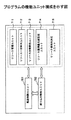
図22は、上記プログラムの機能ユニット構成を示す図である。図22に示されるように、本発明による転送処理・割り込み処理プログラムは、転送制御ユニット701、割り込み制御ユニット702、リソース管理ユニット711、リソース一括割当ユニット712、リソース分割割当ユニット713、リソース獲得優先度設定ユニット714、及びリソース使用先決定ユニット715を含む。転送制御ユニット701は、画像データ入力処理及び画像データ出力処理それぞれの要求に応じて、1次記憶装置606と2次記憶装置607との間のデータ転送処理を制御・実行する。割り込み制御ユニット702は、このデータ転送処理に対する割り込み動作を制御する。データ転送処理・割り込み処理を実行するに当り、具体的には、リソース管理ユニット711、リソース一括割当ユニット712、リソース分割割当ユニット713、リソース獲得優先度設定ユニット714、及びリソース使用先決定ユニット715が用いられる。
【0137】
リソース管理ユニット711は、リソースを使用するジョブが他からの割り込みを許可するジョブであるか或いは他からの割り込みを許可しないジョブであるかに応じて、分割的なリソース割当て或いは一括的なリソース割当てを各ジョブに対応させる。ここで分割的なリソース割当ては、リソース分割割当ユニット713により実行され、ジョブを分割して得られる各分割部分に対して逐次リソースの獲得・開放を行なうようにジョブを実行する。一括的なリソース割当ては、リソース一括割当ユニット712により実行され、一度のリソース獲得・開放を行うだけでジョブを一括的に実行する。またリソース獲得優先度設定ユニット714は、リソース要求が競合状態にある場合に、リソースを獲得する各ジョブの優先度を設定するものである。リソース使用先決定ユニット715は、リソース要求が競合状態にある場合に、リソース獲得優先度設定ユニット714が設定する優先度に応じて、リソースを獲得して使用するジョブを決定する。
【0138】
図22の機能ユニット構成は、本発明の割り込み制御処理をパーソナルコンピュータやワークステーション等のコンピュータで実施する場合に限られず、図5に示す画像形成装置においてCPU508で実施する場合にも同様に適用可能な機能構成である。即ち、CPU508は、画像メモリーコントローラ505を介して、画像メモリー506(1次記憶装置606及び2次記憶装置607)のデータの書き込み及び読み出しを行うが、この際に例えば図22に示されるような機能ユニットを使用して、各転送処理の制御、割り込み処理の制御、或いはリソース制御等を実行すればよい。
【0139】
以上、本発明を実施例に基づいて説明したが、本発明は上記実施例に限定されるものではなく、特許請求の範囲に記載の範囲内で様々な変形が可能である。
【発明の効果】
以上説明したように、請求項1に記載の発明によれば、外部から供給される画像データを入力する画像入力手段と、該画像入力手段で入力された画像データを記憶保持し出力可能な画像記憶手段と、該画像記憶手段に記憶された画像データを読み出し可視画像形成する画像形成手段と、前記画像入力手段で入力された画像データを前記画像記憶手段に記憶するときに圧縮し、前記画像記憶手段に記憶された画像データを読み出すときに伸張する 画像圧縮伸張手段とを有する画像形成装置において、前記画像記憶手段に対する画像データの1入力ジョブ実行時、または画像データの1印刷出力ジョブ実行時に、リソースの取得および解放を1回実行する第1のリソース実行手段と、前記画像記憶手段に対する画像データの1入力ジョブ実行時、または画像データの1印刷出力ジョブ実行時に、リソースの取得および解放を複数回実行する第2のリソース実行手段と、前記第1のリソース実行手段と前記第2のリソース実行手段のいずれかを前記ジョブ内容に応じて選択実行させるリソース管理手段と、複数ジョブによるリソース競合したときにおけるリソース取得の優先順位を設定するリソース獲得優先度設定手段と、前記リソース競合時に前記リソース獲得優先度設定手段の設定に基づき、リソース使用先を決定するリソース使用先決定手段と、を具備し、前記画像記憶手段は、前記画像入力手段から入力された画像データを一時記憶するための1次記憶手段と、該1次記憶手段に入力された画像データを転送記憶する2次記憶手段から構成され、前記圧縮伸張手段は、前記画像入力手段から前記1次記憶手段への画像データ入力時に該画像データを圧縮し、前記画像形成手段で前記1次記憶手段からの画像データ読み出し時に該画像データを伸張する第1の画像圧縮伸張手段と、前記2次記憶手段への入力時に画像データを圧縮し、前記2次記憶手段からの読み出し時に画像データを伸張する第2の画像圧縮伸張手段とで構成され、前記リソース管理手段は、前記第2のリソース実行手段がリソースの取得および解放を複数回実施するとき、(「リソース取得―リソース解放」時間間隔)<[(転送要求発生から転送準備終了までの許容時間)―(画像転送時間)]の条件を満たすタイミングでリソース解放するよう制御するので、画像データの転送処理中に他の画像データの転送を割り込み処理できるようになり、印刷のための画像データを高速に準備でき、生産性の高い印刷動作を実現できるという効果を奏する。また入力時のリソース解放をおこなう間隔を規定して、リソース解放をおこなうため、効率的な転送制御が実行できるようになる。即ち、印刷時の転送要求発生から転送準備終了までの許容時間で画像転送がおこなえるタイミングでリソース解放をおこなうことができるようになり、印刷出力のための画像の準備を保証できるという効果を奏する。
【図面の簡単な説明】
【図1】この発明の本実施の形態にかかる画像形成装置の全体構成を示す正面図である。
【図2】この発明の画像形成装置に設けられる操作部を示す図である。
【図3】この発明の画像形成装置に設けられる操作部の液晶タッチパネルの表示の一例を示す図である。
【図4】この発明の画像形成装置の制御装置を示すブロック図である。
【図5】画像処理ユニットの内部構成を示すブロック図である。
【図6】画像メモリーコントローラと、画像メモリーの内部構成を示すブロック図である。
【図7】画像データの転送処理内容を示すフローチャートである。
【図8】画像転送中に他の画像転送要求が発生した場合のタイムチャートである。
【図9】転送処理実行待ち順序を示す概要図である。
【図10】画像転送中に他の画像転送要求が発生した場合のタイムチャートである。
【図11】画像転送中に他の画像転送要求が発生した場合のタイムチャートである。
【図12】割り込み転送処理後のつぎの転送処理を決定する手順を示すフローチャートである。
【図13】単一ドラム方式のカラー印刷ユニットの構成の一例を示す図である。
【図14】黒Bk、シアンC、マゼンタM、及びイエローYを順次印刷する際の動作を説明するための図である。
【図15】画像データの転送受け付け処理内容を示すフローチャートである。
【図16】転送処理実行待ち順序を示す概要図である。
【図17】画像データ転送にかかるリソース獲得制御内容を示すフローチャートである。
【図18】画像データ転送中に他の画像データ転送要求が発生した場合のリソース管理内容を示すタイムチャートである。
【図19】画像データの転送処理内容を示すフローチャートである。
【図20】画像データの転送サイズとリソース解放の関係を示すタイミングチャートである。
【図21】1次圧縮/伸張部のリソース構成を示す図である。
【図22】プログラムの機能ユニット構成を示す図である。
【符号の説明】
101 自動原稿送り装置(ADF)
102 原稿台
103 給送ローラ
104 給送ベルト
105 排送ローラ
108 第1トレイ
109 第2トレイ
110 第3トレイ
111 第1給紙装置
112 第2給紙装置
113 第3給紙装置
114 縦搬送ユニット
115 感光体
117 定着ユニット
118 排紙ユニット
119 排紙トレイ
121 両面給紙ユニット
122 分岐爪
126 搬送モータ
127 現像ユニット
150 読み取りユニット
151 露光ランプ
152 第1ミラー
153 レンズ
154 CCD(イメージセンサ)
155 第2ミラー
156 第3ミラー
157 書き込みユニット
158 レーザ出力ユニット
159 結像レンズ
160 ミラー
200 操作部
201 液晶タッチパネル
202 テンキー
203 クリア/ストップキー
204 プリントキー
205 モードクリアキー
207 機能キー
208 メッセージ表示
400 メインコントローラ
402 画像処理ユニット(IPU)
403 メインモータ
404〜406 第1〜第3給紙クラッチ
407 中間クラッチ
501 A/Dコンバータ
502 シェーディング補正部
503 画像処理部
504 セレクタ
505 画像メモリーコントローラ
506 画像メモリー
507 I/Oポート
508 CPU
509 ROM
510 RAM
511 書き込みγ補正ユニット
512 変倍処理部
513 画像データバス
600 データ入出力制御部
601 入力データセレクタ
602 画像合成部
603 1次圧縮/伸張部
604 出力データセレクタ
605 2次圧縮/伸張部
606 1次記憶装置
607 2次記憶装置[0001]
BACKGROUND OF THE INVENTION
The present invention relates to an image forming apparatus having a function of storing input images, such as a digital copying machine, a facsimile, a printer, and a scanner, and printing out the stored images, and more specifically, in a secondary storage device such as a hard disk. Image forming apparatus for storing images, transferring image data to a semiconductor memory for printing, and printing, image transfer control method used in the apparatus, program for causing computer to execute the method, and computer storing the program The present invention relates to a readable recording medium.
[Prior art]
2. Description of the Related Art Recent image forming apparatuses have a function of processing an image for printing, and such an apparatus stores image data for image processing in a secondary storage device such as a hard disk device (HDD). It is like that. At the time of printing, an image is transferred from the secondary storage device to the semiconductor memory and then printed.
[0002]
As an example of such a conventional image forming apparatus, a technique disclosed in Japanese Patent Laid-Open No. 9-319662 will be described. The data transfer speed of the hard disk device becomes slower as the track to be accessed approaches the inner circumference. When a hard disk device is used as a frame memory of a page print type image forming apparatus, transfer of image data stored in an area with a low transfer speed may be omitted.
[0003]
Therefore, image data with high importance is stored in an area where transfer is fast, so that a reproduced image with high importance is prevented from being deteriorated. For this purpose, the data storage control unit is configured to divide the storage area of the hard disk device into storage areas for each transfer speed, and store the highly important image data compressed by the compression / decompression unit in the storage area with a high transfer speed. is there.
[0004]
In recent years, with the progress of digitalization of copying machines, processing and editing that apply storage of image data in a memory have come to be performed. For example, there is a function called electronic sorting, in which image data for a plurality of documents is stored in a memory, and a specified number of copies are collectively copied and output to eliminate sorting work after printing.
[0005]
With this electronic sort function, it is necessary to store a plurality of pieces of image data in a memory, so that the memory cost becomes enormous if it is realized only with a semiconductor memory (a page memory for printing). For this reason, both a semiconductor memory (print page memory) and a storage memory (secondary storage device) are used, and a hard disk device or the like that is cheaper than the semiconductor memory is generally used as the storage memory.
[0006]
The above-described semiconductor memory is used as a buffer memory for absorbing the difference between the transfer speed on the secondary storage device side and the input / output image transfer speed, and for realizing an image rotation function by address operation when reading the memory.
[Problems to be solved by the invention]
In the secondary storage device, sequentially written (stored) data is read as sequential data in the same sequence. Here, when printing an image stored in the secondary storage device, a procedure described below is required.
(1) Transfer image data from secondary storage device (hard disk drive etc.) to semiconductor memory (page memory for printing)
(2) Output the image data of the semiconductor memory (page memory for printing) to the printing section
[0007]
However, in general, the transfer speed of the secondary storage device is slower than the image transfer speed of the input / output operation, and only one of continuous data input or continuous data output is executed for a certain amount of data. Can not. Therefore, when performing image printing, the time required for the transfer process (1) and the transfer timing are important. With the recent increase in printing speed and color printing, it is important how quickly image data can be prepared (transferred) from the secondary storage device to the semiconductor memory (page memory for printing) at a desired timing. ing.
[0008]
If the image data cannot be prepared within the required time, an “image shift” occurs in which the image mounting position shifts with respect to the transfer paper. In particular, during color printing, a miscopy occurs in which the color of MCYK shifts.
[0009]
In order to solve the above-described problems caused by the prior art, the present invention uses a large-capacity secondary storage device as an image memory, efficiently transfers image data to the primary storage device, and achieves high speed and high productivity. An object of the present invention is to provide an image forming apparatus, an image transfer control method used in the apparatus, a program for causing a computer to execute the method, and a computer-readable recording medium on which the program is recorded.
[Means for Solving the Problems]
In order to solve the above-described problems and achieve the object, an image forming apparatus according to the invention of
[0010]
According to the first aspect of the present invention, the transfer of other image data can be interrupted during the transfer process of the image data, the image data for printing can be prepared at high speed, and a highly productive printing operation can be performed. realizable.In addition, the resource release is performed by defining the interval for releasing the resource at the time of input, so that efficient transfer control can be executed. That is, it becomes possible to release resources at a timing at which image transfer can be performed within an allowable time from generation of a transfer request at the time of printing to completion of transfer preparation, and it is possible to guarantee preparation of an image for print output.
DETAILED DESCRIPTION OF THE INVENTION
DETAILED DESCRIPTION Exemplary embodiments of an image forming apparatus, an image transfer control method, a program for causing a computer to execute the method, and a computer-readable recording medium on which the program is recorded are described below with reference to the accompanying drawings. This will be described in detail.
[0011]
FIG. 1 is a front view showing the overall configuration of the image forming apparatus of the present invention. An automatic document feeder (hereinafter referred to as ADF) 101 is provided at the top of the apparatus. A document bundle with the image surface facing upward is placed on the document table 102 on the upper surface of the ADF 101. By pressing a start key (not shown) on the
[0012]
The
[0013]
The
[0014]
When reading an image of a document, the first carriage and the second carriage are mechanically moved and controlled at a relative speed of 2: 1 so that the optical path length does not change. This optical scanning system is driven by a scanner drive motor (not shown). The image of the document is read by a CCD (image sensor) 154 and converted into an electric signal (image data).
[0015]
The
[0016]
The laser light output from the
[0017]
Three trays are provided on the lower side of the apparatus, and transfer sheets are stacked on the
[0018]
The image data read by the
[0019]
When an image is formed on both sides of the transfer paper, the transfer paper fed from each of the (paper feed)
[0020]
Thereafter, the transfer paper stocked in the double-sided
[0021]
The
[0022]
FIG. 2 is a diagram illustrating the
[0023]
FIG. 3 is a diagram illustrating an example of display on the liquid
[0024]
FIG. 4 is a block diagram illustrating a control device of the image forming apparatus. The
[0025]
Each distributed control device and the
[0026]
FIG. 5 is a block diagram showing an internal configuration of the image processing unit (IPU) 402. Reflection of light emitted from the
[0027]
The
[0028]
In FIG. 5, in addition to the image data input from the
[0029]
In addition, a CPU 508 for setting the
[0030]
Next, FIG. 6 is a block diagram showing an internal configuration of the
[0031]
The
[0032]
The
[0033]
When the
[0034]
Next, specific operation contents of each application of the primary storage device 606 and the
<Example 1> One copy in a copy application
[0035]
In the case of one copy, first, image data from the scanner (CCD 154) is input to the primary storage device 606 of the
<Example 2> Sorting in a copy application (multiple copies)
[0036]
Even in the case of two or more copies, image data from the scanner (CCD 154) is input to the primary storage device 606 first. In the first copy, the image data is output from the primary storage device 606 to the image forming device (writing unit 157) and stored in the
<Example 3> Image storage from a scanner
[0037]
In this case, the image data from the scanner (CCD 154) is accumulated in the
<Example 4> Printing from an external input device (for example, a personal computer)
[0038]
In this case, although substantially the same as <Example 1> and <Example 2>, the image data is input from an external input device via the I /
<Example 5> Image storage from an external input device
[0039]
In this case, it is almost the same as <Example 3>, and the input source of the image data is not a scanner but an external input device.
<Example 6> Printing accumulated image
[0040]
When printing the image stored in the
[0041]
Next, image data input / output processing contents in the image memory controller 505 (data input / output control unit 600) will be described with reference to FIG. Here, the case where the
<1> Image input (save to image memory 506)
[0042]
The
[0043]
Next, the image selected by the
[0044]
Next, the image data processed by the
<2> Image output (reading from image memory 506)
[0045]
At the time of image output, image data stored in the primary storage device 606 is read. When image data to be output is stored in the primary storage device 606, the primary compression /
[0046]
Next, the contents of the image data transfer process will be described with reference to the flowchart shown in FIG. FIG. 7 shows the processing contents when a transfer request from the primary storage device 606 to the
[0047]
When a transfer request is generated (step S701), it is next determined whether the request is a transfer processing request for image input (step S702) or a transfer processing request for image printing (step S703).
[0048]
When the transfer process for image input is requested (step S702: Yes), it is determined whether the transfer process is currently being executed (step S708). If the transfer process is being executed (step S708: Yes), the transfer process is awaiting execution. The requested transfer process is registered in the queue (step S709), and if the transfer process is not being executed (step S708: No), the transfer process for the image input requested to be transferred is executed (step S710). Exit.
[0049]
When there is no transfer processing request for image input (step S702: No), it is determined whether there is a transfer processing request for image printing (step S703), and when there is no transfer processing request (step S703: No). , Exit the process. When a transfer process request for image printing is requested (step S703: Yes), it is determined whether the transfer process for image input is currently being executed (step S704).
[0050]
If the image input transfer process is being executed (step S704: Yes), first, the process for interrupting the image input transfer process currently being executed is executed (step S706), and the transfer process for which there was a transfer request in the transfer interruption queue. Is registered (step S711), and step S707 is executed. On the other hand, if the image input transfer process is not being executed (step S704: No), it is determined whether the image print transfer process is currently being executed (step S705).
[0051]
If the transfer process for image printing is currently being executed (step S705: Yes), the process proceeds to step S709. If the transfer process is not being executed (S705: No), step S707 is executed. In step S707, the transfer process for image printing requested for transfer is executed, and the process exits.
[0052]
Among the processes described above, there is no transfer process being executed in the process order of “Step S702 → Step S708 → Step S710” and the process order of “Step S702 → Step S703 → Step S704 → Step S705”. Perform the requested transfer process.
[0053]
On the other hand, the processing order of “step S702 → step S703 → step S704 → step S705 → step S709” corresponds to a case where an image print request for another image is generated during transfer for image printing.
[0054]
An example of the image transfer operation in this case is shown in the time chart of FIG. In the figure, HDD indicates a hard disk device used for the
[0055]
When waiting for execution of such transfer processing, execution is sequentially processed according to the outline diagram of the execution waiting order shown in FIG. The transfer process requested to be transferred in step S709 in FIG. 7 is registered in the “transfer process execution queue” as shown in FIG. 9A.
[0056]
In the case of stacking in the queue, if the current state is as shown in FIG. 9A, it indicates that IN_1, OUT_1, IN_2, and IN_3 have already been registered in the queue. If there is a new registration here, No. Since 5 queues are available, they are registered here. Note that IN is image data input transfer processing, and OUT is image data output (print) transfer processing.
[0057]
Further, the processing order of “step S702 → step S703 → step S704 → step S706 → step S711 → step S707” corresponds to a case where an image print request for another image is generated during transfer for image input. . An example of the image transfer operation in this case is shown in the time chart of FIG.
[0058]
In this case, the transfer process of the input of the
[0059]
In this case, the interruption interrupts the data transfer from the primary storage device 606 to the
[0060]
Next, the processing order of “step S702 → step S708 → step S709” is such that when a transfer request for inputting another image is generated during transfer for image input, or another image is being transferred for image printing. This corresponds to a case where a transfer request for input is generated. An example of the image transfer operation in this case is shown in the time chart of FIG.
[0061]
As shown in FIG. 11A, when an input transfer request for another
[0062]
As shown in FIG. 11B, when an
[0063]
As described above, the unit of image data transfer in consideration of the interrupt during execution of transfer processing is a unit smaller than one image for data transfer from the primary storage device 606 to the
[0064]
Next, FIG. 12 is a flowchart showing a procedure for determining the next transfer processing after the interrupt transfer. When the transfer process being executed is completed, a process for determining a transfer process to be executed next is executed (step S1200).
[0065]
First, in step S711 (see FIG. 7) described above, the transfer interruption process is executed, and the interrupted transfer process content is registered (entry) in the transfer interruption queue, so the presence or absence of this entry is checked (step S1201). . If an entry (job) is detected (step S1201: Yes), the interrupted transfer process is restarted and continued (step S1208), and the process for determining the next transfer execution process ends.
[0066]
If there is no transfer interruption (step S1201: No), it is checked whether there is a transfer waiting queue (job) or not (step S1202). The entry to the transfer waiting queue is performed when the transfer is already in progress in S709 of FIG.
[0067]
If there is an entry in the transfer process execution waiting queue (step S1202: Yes), a job to be transferred is determined. If there is no entry (step S1202: No), the next transfer process determination process is terminated.
[0068]
When a job to be transferred is determined, it is normally performed in the order of FIFO (FIRST: first output), but when executing print priority processing, it is used for printing in an entry to ensure that an image is prepared at the time of a print request. The operation differs depending on whether there is a transfer process. That is, search is performed in the order of registration in the transfer process execution waiting queue, and the presence or absence of a transfer process request for job printing is detected (step S1203).
[0069]
When step S1203 is Yes, the processing order is “step S1203 → step S1206 → step S1207”. If there is no transfer processing for printing in the entry, the transfer processing is performed in the order in which the queues are stacked (FIFO: first output) (the state shown in FIG. 9A).
[0070]
When step S1203 is No, the processing order is “step S1203 → step S1204 → step S1205”. If the entry has a transfer process for printing, the print priority process is executed. In order to reliably prepare an image at the time of a print request, a transfer process for printing previously entered in the queue is executed. In this case, the print transfer request OUT_1 shown in FIG. 9A is preferentially executed, and the FIFO after execution is in the state shown in FIG. 9B.
[0071]
Then, the executed transfer process is deleted from the transfer process execution queue, and a new transfer process execution queue is created by sequentially shifting the transfer process contents entered in the subsequent stage to an empty queue. (Step S1205, Step S1207).
[0072]
The control of the image data transfer process described above has a general advantage that image data for printing can be prepared at high speed and a highly productive print operation can be realized. However, as described below, the color print process can be performed. In the case of application, it is possible to realize a reliable printing operation particularly by exhibiting the effect.
[0073]
FIG. 13 is a diagram illustrating an example of the configuration of a single drum type color printing unit. The configuration of FIG. 13 corresponds to the
[0074]
In FIG. 13, the image forming unit 21 includes a photoreceptor 24, a
[0075]
The
[0076]
In the color printing unit of FIG. 13, a full-color image is formed as follows.
[0077]
First, in the image forming unit 21, the photosensitive member 24 and the
[0078]
When the primary transfer of the black image Bk of the first color is completed, the
[0079]
The full color toner image formed on the
[0080]
FIG. 14 is a diagram for explaining the operation when black Bk, cyan C, magenta M, and yellow Y are sequentially printed as described above.
[0081]
In the single drum type color printing unit as described above, the image data stored in the primary storage device 606 is read at the time of printing operation, and the
[0082]
The primary storage device 606 is a page memory in which the storage space is managed in units of pages and images are temporarily stored in units of pages. In the case of color data, each color constitutes each page.
[0083]
In the sequential printing operation of Bk, C, M, and Y in FIG. 14, when the image data of each color does not exist in the page memory (primary storage device 606) and exists in the
[0084]
If there is enough memory space on the page memory (primary storage device 606), it is also possible to read out all color image data from the
[0085]
As described above, in the single drum type color printing unit, once the image forming operation is started, it is necessary to execute the image forming process of Bk, C, M, and Y at predetermined intervals. It is necessary to prepare the data of each image before the timing. The control of the image data transfer process of the present invention can prepare image data for printing at high speed by interruption. Accordingly, in the single drum type color printing process, the output image data is sequentially transferred at a necessary timing after the start of the image forming cycle, thereby realizing a reliable printing operation.
[0086]
At this time, input data to the primary storage device 606 (data input from the scanner) can be kept waiting as necessary. This is because the image reading operation by the scanner may be started for the first time when the available memory space is secured in the primary storage device 606 and secured. Therefore, even if the data output from the primary storage device 606 is given priority over the data input, there is no particular problem on the input side, and there is an effect that a reliable printing operation can be realized on the output side as described above. can get.
[0087]
In the above, the control of the transfer process between the primary storage device and the secondary storage device has been described from the viewpoint of the interruption of the image data transfer process, but a specific method for realizing the interrupt process has been particularly described. Absent. In the following, a description will be given of how to implement an interrupt for the transfer processing between the primary storage device and the secondary storage device.
[0088]
In the following description, image data processing is regarded as one job based on the same concept as a software process. Furthermore, by associating acquisition and release of necessary resources with the start and stop of the job, the execution of the job is controlled to enable interrupt processing.
[0089]
FIG. 15 is a flowchart showing the contents of the transfer acceptance process when a transfer request from the primary storage device 606 to the
[0090]
The transfer acceptance process illustrated in FIG. 15 is a program module that is executed each time the transfer process is executed. This module is a resource release notification issued when a transfer request is generated or in step S1104 of FIG. 19 described later. It is a module that is called (activated) when receiving.
[0091]
It is determined whether or not there is a transfer request (step S701), and when a transfer request occurs (step S701: Yes), it is determined whether or not the
[0092]
When waiting for execution of such transfer processing, execution is sequentially performed according to the outline diagram of the execution waiting order shown in FIG. The transfer process requested to be transferred in step S705 in FIG. 15 is registered in the “transfer process execution queue” as shown in FIG.
[0093]
In the case of loading in the queue, if the current state is as shown in FIG. 16A, it indicates that the queue is already registered in the order of IN_1, OUT_1, IN_2, IN_3. If there is a new registration here, No. Since 5 queues are available, they are registered here. Note that IN is image data input transfer processing, and OUT is image data output (print) transfer processing.
[0094]
If the transfer is not in progress (step S704: No), since the
[0095]
Even when there is no transfer request (step S701: No) and there is a resource release notification (step S702: Yes), the
[0096]
FIG. 17 is a flowchart showing the contents of resource acquisition control (step S703 in FIG. 15). In resource acquisition control, when resource acquisition competes (a plurality of resource request destinations exist), re-evaluation processing is performed based on the priority of acquiring resources among jobs waiting for resource acquisition. The resource acquisition control shown in this figure is called (activated) when there is a new transfer request and when a resource is released.
[0097]
First, it is determined whether there is a job for which transfer processing is suspended in the transfer suspension queue or transfer processing execution queue (step S901). If there is a job in this determination (S901: Yes), it is determined whether there is a transfer processing waiting job in the transfer processing execution waiting queue (step S902). If there is a job in this determination (step S902: Yes), search is performed in the order of registration in the transfer processing execution queue, and it is determined whether there is a transfer processing request for job printing (reading of image data from the secondary storage device 607). (Step S903). When there is no transfer processing request for job printing (step S903: No) and when there is no transfer processing waiting job (step S902: No), it is determined whether there is a job for which transfer processing is suspended in the transfer suspension queue. (Step S904).
[0098]
According to the processing order of “step S901-step S902-step S903-step S904”, it is determined whether there is a job waiting in the “transfer processing execution waiting queue” or “transfer interruption queue” as to whether resource acquisition is competing. judge. Further, the priority order for acquiring the resource depends on the processing order in “Step S901-Step S902-Step S903-Step S904”, and the priority order is as follows.
[0099]
"Resource acquisition request at output> Acquisition request during transfer interruption> Transfer request at input"
[0100]
By setting the priority order, the priority order of resource acquisition can be defined, transfer for output of image data from the
[0101]
If there is no job for which transfer processing is suspended in the transfer suspension queue or transfer processing execution waiting queue (step S901: No), it is determined whether it is resource acquisition processing for a new transfer request (step S907). If it is a resource acquisition process for a new transfer request (step S907: Yes), a resource is allocated to the transfer job for which transfer has been supplied (step S908), and the process proceeds to the execution of the transfer process for the resource acquired job (step S912). If it is not the resource acquisition process of the new transfer request (step S907: No), the resource acquisition control is exited without executing the transfer process.
[0102]
The processing order of “step S907-step S908-step S912” corresponds to a case where there is no transfer interruption processing and there is a new transfer request in a state where there is no waiting in the transfer processing execution waiting queue ( (See FIG. 18 (time c)).
[0103]
FIG. 18 is a time chart for explaining each state of resource lock in the secondary storage device 607 (hard disk device as a specific example). As shown, each event of 0-4 occurs. In each event, the upper column is an image input system, and the lower column is an image output system.
[0104]
0: Explains the state of repeatedly acquiring and releasing resources during image input transfer
[0105]
1: When print (output) transfer occurs during image input transfer
[0106]
2: When another image input transfer request occurs during image input transfer
[0107]
3: When an input image transfer request occurs during printing (output) image transfer
[0108]
4: When another image transfer request occurs during print (output) image transfer
[0109]
In the case of FIG. 18 (time c) described above, the resources may be allocated to those requested unconditionally.
[0110]
If there is a job whose transfer processing is suspended in the transfer suspension queue (step S904: Yes), resources are allocated to the transfer job registered in the transfer suspension queue (step S909), and the transfer processing is executed (step S912).
[0111]
The processing order of “step S909 to step S912” is a case where there is a transfer interruption process and there is no waiting in the transfer process execution waiting queue or there is no waiting for a transfer process request for printing. . This corresponds to (time a) in FIG. In this case, since there is no transfer process for printing, resources are allocated to this process in order to continue the transfer process during the transfer interruption.
[0112]
If there is no job whose transfer process is suspended in the transfer suspension queue (step S904: No), a resource is allocated to the transfer process of the first (first registered) job in the transfer process execution waiting queue (step S905). Then, after deleting the head job of the transfer process execution waiting queue from the queue and shifting the queue of empty queues (step S906), the transfer process is executed (step S912).
[0113]
The processing order of “step S905 to step S906 to step S912” is that there is no transfer interruption processing, there is no waiting in the transfer processing execution waiting queue, and there is a waiting for a transfer processing request for printing. This is the case. In FIG. 18, this corresponds to (time d). In this case, there is no transfer process for printing, and there is no transfer interrupted, so the first transfer process that has received the transfer request first in the transfer queue is executed.
[0114]
If there is a transfer processing request for job printing (reading of image data from the secondary storage device 607) in the order of registration in the transfer processing execution waiting queue, the print found in the search is found (step S903: Yes). A resource is allocated to the transfer process for use (step S910), the head job in the transfer process execution waiting queue is deleted from the queue, the arrangement of empty queues is shifted (step S911), and the transfer process is executed (step S912).
[0115]
The processing order of “step S910-step S911-step S912” is a case where there is a waiting in the transfer processing execution waiting queue and a waiting for a transfer processing request for printing. In this case, resources are preferentially assigned to the print transfer process. As a result, it is possible to ensure output priority and to accurately prepare an image for printing.
[0116]
Next, FIG. 19 is a flowchart showing the contents of the transfer process (step S912 in FIG. 17) at the time of resource acquisition. In the figure, the control content is shown in which “resource acquisition-release” is repeated a plurality of times each time the transfer process is completed. The resource lock (occupancy) and release state of the corresponding secondary storage device (HDD) 607 is described in
[0117]
When executing transfer processing of a job that has acquired a resource (step S912), it is first determined whether or not the resource is subject to division control (control that repeats “resource acquisition-release” a plurality of times) (step S1101). . In the case of printing priority (priority of output of image data from the secondary storage device 607), this condition divides and controls "execution processing of transfer for image input" to determine whether or not resources are released multiple times. become.
[0118]
If the job that has acquired the resource is not subject to resource division control (step S1101: No), execution of transfer processing (step S1102) → determination of whether or not all size transfer processing has been completed (step S1103) is repeated to determine all sizes. When the transfer is completed (step S1103: Yes), the resource of the
[0119]
For example, as shown in each
[0120]
Also, if it is a target of division control (control to repeat “resource acquisition-release” a plurality of times) (step S1101: Yes), execution of transfer processing (step S1105) → determining whether or not prescribed size transfer processing has been completed (step S1106) is repeated and when the specified size transfer is completed (step S1106: Yes), even if the transfer of all sizes is not completed, it is registered in the transfer interruption queue (step S1107) and the resources of the
[0121]
This state is shown as
[0122]
As described above, there is a slight delay between the generation of a transfer request for printing and the acquisition of resources. Therefore, by prescribing the time from “resource acquisition to release” when resource acquisition is divided, image preparation for printing can be guaranteed.
[0123]
That is, when “resource acquisition-resource release” is performed a plurality of times, resource release is performed within the following condition time so that the image development time can be guaranteed.
("Resource acquisition-resource release" time interval) <[(allowable time between generation of transfer request and completion of transfer preparation)-(image transfer time)]
[0124]
Resources are released for the transfer processing for printing that performs resource release, but resources must not be released at the timing when image transfer can be performed between the transfer request generation at the time of printing and the allowable time between transfer preparation completion. Is meaningless. Therefore, by setting the time for “resource acquisition-resource release” that satisfies the above conditions, image preparation for printing can be guaranteed.
[0125]
FIG. 20 is a timing chart for explaining the resource release time interval. If the time interval of “resource acquisition-resource release” is set to be short, image guarantee is performed, and an extra time is generated for transfer. However, if resource release is repeated in small increments, the number of transfer divisions increases too much, increasing overhead and reducing efficiency.
[0126]
Therefore, as shown in the figure, this transfer time control is used at a time interval adapted to the transfer size at the time of division control. If the transfer time is managed using a timer, the software overhead for time management becomes heavy and the efficiency becomes poor. For this reason, by adopting a configuration in which the required transfer time is calculated from the transfer size and transfer speed, the load can be reduced in terms of software and efficiency can be improved. With the configuration described above, the print priority process can be realized, and an image for printing can be reliably and quickly prepared, so that a highly productive printing operation can be realized.
[0127]
In the resource management described in the above embodiment, after image data is input to the
[0128]
On the other hand, when image data is captured and input to the image memory 506 (primary storage device 606), image data cannot be captured correctly if resources are allocated to other jobs during a scan with a slow transfer speed such as a scanner. . In the case of such job contents, it is necessary to continue to occupy the scanner resource from the start of capture to the completion of capture even when image data is input. In addition, it is necessary to perform exclusive control so that resources are not used by other jobs.
[0129]
As described above, the image forming apparatus of the present invention is roughly divided into two different types of resources. Therefore, optimal resource management can be realized by switching control of the resource management mode according to the contents of the job. This switching control can be dealt with by setting in advance the above-described priority for each job content and the presence / absence of divided transfer.
[0130]
In the above description, the image data transfer process is regarded as one job in the same concept as the software process, and further, acquisition and release of necessary resources are associated with the start and stop of the job. Control execution and enable interrupt handling. In the present invention, the realization of the interrupt by the resource acquisition and release process is not limited to the image data transfer process, and can be applied to various other image data processes.
[0131]
FIG. 21 is a diagram showing a resource configuration of the primary compression /
[0132]
As shown in FIG. 21, the primary compression /
[0133]
The
[0134]
In the present invention, when a certain job is executed, the job is divided by division control, and resources are sequentially acquired and released for each divided part, thereby interrupting use of the resource by other jobs. There are cases where a job is completed while being permitted, and cases where a job is completed without allowing the interrupt use of the resource by other jobs by executing the job in a batch by acquiring and releasing resources once. is there. Such resource control can also be applied to resources such as the above-described
[0135]
Each configuration relating to the image data transfer processing described in the present embodiment can be realized by executing a program prepared in advance on a computer such as a personal computer or a workstation. This program is recorded on a computer-readable recording medium such as a hard disk, floppy disk, CD-ROM, MO, or DVD, and is executed by being read from the recording medium by the computer. The program can be distributed via the recording medium and a network such as the Internet.
[0136]
FIG. 22 is a diagram showing a functional unit configuration of the program. As shown in FIG. 22, the transfer processing / interrupt processing program according to the present invention includes a
[0137]
The
[0138]
The functional unit configuration of FIG. 22 is not limited to the case where the interrupt control processing of the present invention is performed by a computer such as a personal computer or a workstation, but can be similarly applied to the case where the CPU 508 is implemented in the image forming apparatus shown in FIG. Functional configuration. That is, the CPU 508 writes and reads data in and from the image memory 506 (primary storage device 606 and secondary storage device 607) via the
[0139]
As mentioned above, although this invention was demonstrated based on the Example, this invention is not limited to the said Example, A various deformation | transformation is possible within the range as described in a claim.
【The invention's effect】
As described above, according to the invention described in
[Brief description of the drawings]
FIG. 1 is a front view showing an overall configuration of an image forming apparatus according to an embodiment of the present invention.
FIG. 2 is a diagram illustrating an operation unit provided in the image forming apparatus of the present invention.
FIG. 3 is a diagram showing an example of a display on a liquid crystal touch panel of an operation unit provided in the image forming apparatus of the present invention.
FIG. 4 is a block diagram illustrating a control device of the image forming apparatus according to the present invention.
FIG. 5 is a block diagram showing an internal configuration of an image processing unit.
FIG. 6 is a block diagram illustrating an internal configuration of an image memory controller and an image memory.
FIG. 7 is a flowchart showing image data transfer processing contents;
FIG. 8 is a time chart when another image transfer request is generated during image transfer.
FIG. 9 is a schematic diagram showing a transfer processing execution waiting order;
FIG. 10 is a time chart when another image transfer request is generated during image transfer.
FIG. 11 is a time chart when another image transfer request is generated during image transfer.
FIG. 12 is a flowchart illustrating a procedure for determining a next transfer process after an interrupt transfer process;
FIG. 13 is a diagram illustrating an example of a configuration of a single drum type color printing unit.
FIG. 14 is a diagram for describing an operation when black Bk, cyan C, magenta M, and yellow Y are sequentially printed.
FIG. 15 is a flowchart illustrating image data transfer acceptance processing.
FIG. 16 is a schematic diagram showing a transfer processing execution waiting order;
FIG. 17 is a flowchart showing resource acquisition control contents related to image data transfer.
FIG. 18 is a time chart showing resource management contents when another image data transfer request is generated during image data transfer.
FIG. 19 is a flowchart illustrating image data transfer processing.
FIG. 20 is a timing chart showing the relationship between the transfer size of image data and resource release.
FIG. 21 is a diagram illustrating a resource configuration of a primary compression / decompression unit.
FIG. 22 is a diagram illustrating a functional unit configuration of a program.
[Explanation of symbols]
101 Automatic document feeder (ADF)
102 Document table
103 Feed roller
104 Feed belt
105 Discharge roller
108 1st tray
109 Second tray
110 Third tray
111 First paper feeder
112 Second paper feeder
113 Third paper feeder
114 Vertical transport unit
115 photoconductor
117 Fixing unit
118 Paper discharge unit
119 Output tray
121 Double-sided paper feed unit
122 branch nail
126 Conveyor motor
127 Development unit
150 reading unit
151 Exposure lamp
152 First mirror
153 lens
154 CCD (image sensor)
155 Second mirror
156 Third mirror
157 Writing unit
158 Laser output unit
159 Imaging lens
160 Mirror
200 Operation unit
201 LCD touch panel
202 numeric keypad
203 Clear / Stop key
204 Print key
205 Mode clear key
207 Function key
208 Message display
400 Main controller
402 Image processing unit (IPU)
403 Main motor
404 to 406 First to third paper feed clutches
407 Intermediate clutch
501 A / D converter
502 Shading correction unit
503 Image processing unit
504 selector
505 Image memory controller
506 Image memory
507 I / O port
508 CPU
509 ROM
510 RAM
511 Writing γ correction unit
512 Scaling processing unit
513 Image data bus
600 Data input / output controller
601 Input data selector
602 Image composition unit
603 Primary compression / decompression unit
604 Output data selector
605 Secondary compression / decompression unit
606 Primary storage device
607 secondary storage device
Claims (1)
該画像入力手段で入力された画像データを記憶保持し出力可能な画像記憶手段と、
該画像記憶手段に記憶された画像データを読み出し可視画像形成する画像形成手段と、
前記画像入力手段で入力された画像データを前記画像記憶手段に記憶するときに圧縮し、前記画像記憶手段に記憶された画像データを読み出すときに伸張する画像圧縮伸張手段と
を有する画像形成装置において、
前記画像記憶手段に対する画像データの1入力ジョブ実行時、または画像データの1印刷出力ジョブ実行時に、リソースの取得および解放を1回実行する第1のリソース実行手段と、
前記画像記憶手段に対する画像データの1入力ジョブ実行時、または画像データの1印刷出力ジョブ実行時に、リソースの取得および解放を複数回実行する第2のリソース実行手段と、
前記第1のリソース実行手段と前記第2のリソース実行手段のいずれかを前記ジョブ内容に応じて選択実行させるリソース管理手段と、
複数ジョブによるリソース競合したときにおけるリソース取得の優先順位を設定するリソース獲得優先度設定手段と、
前記リソース競合時に前記リソース獲得優先度設定手段の設定に基づき、リソース使用先を決定するリソース使用先決定手段と、
を具備し、
前記画像記憶手段は、前記画像入力手段から入力された画像データを一時記憶するための1次記憶手段と、該1次記憶手段に入力された画像データを転送記憶する2次記憶手段から構成され、
前記圧縮伸張手段は、前記画像入力手段から前記1次記憶手段への画像データ入力時に該画像データを圧縮し、前記画像形成手段で前記1次記憶手段からの画像データ読み出し時に該画像データを伸張する第1の画像圧縮伸張手段と、
前記2次記憶手段への入力時に画像データを圧縮し、前記2次記憶手段からの読み出し時に画像データを伸張する第2の画像圧縮伸張手段とで構成され、
前記リソース管理手段は、前記第2のリソース実行手段がリソースの取得および解放を複数回実施するとき、(「リソース取得―リソース解放」時間間隔)<[(転送要求発生から転送準備終了までの許容時間)―(画像転送時間)]の条件を満たすタイミングでリソース解放するよう制御することを特徴とする画像形成装置。Image input means for inputting image data supplied from outside;
Capable of outputting image storage means stores and holds the image data input by said image input means,
Image forming means for forming a visible image read out image data stored in said image storing means,
Image compression / expansion means for compressing the image data input by the image input means when storing the image data in the image storage means, and for expanding the image data stored in the image storage means;
In an image forming apparatus having
First resource execution means for executing resource acquisition and release once at the time of executing one input job of image data to the image storage means or at the time of executing one print output job of image data;
A second resource execution unit that executes acquisition and release of a resource a plurality of times when executing one input job of image data to the image storage unit or when executing one print output job of image data;
Resource management means for selectively executing either the first resource execution means or the second resource execution means according to the job content;
Resource acquisition priority setting means for setting the priority of resource acquisition when resource competition occurs by multiple jobs;
Resource usage destination determining means for determining a resource usage destination based on the setting of the resource acquisition priority setting means at the time of resource competition;
Comprising
The image storage means includes primary storage means for temporarily storing image data input from the image input means, and secondary storage means for transferring and storing image data input to the primary storage means. ,
The compression / decompression unit compresses the image data when the image data is input from the image input unit to the primary storage unit, and decompresses the image data when the image forming unit reads the image data from the primary storage unit. First image compression / expansion means
A second image compression / expansion unit that compresses image data when input to the secondary storage unit and expands image data when read from the secondary storage unit;
When the second resource execution unit performs resource acquisition and release a plurality of times, the resource management unit ((resource acquisition-resource release) time interval) <[(allowance from generation of transfer request to completion of transfer preparation) An image forming apparatus that controls to release resources at a timing that satisfies a condition of (time) − (image transfer time)] .
Priority Applications (5)
| Application Number | Priority Date | Filing Date | Title |
|---|---|---|---|
| JP2002207172A JP3898987B2 (en) | 2001-07-30 | 2002-07-16 | Image forming apparatus, image transfer control method used in the apparatus, program causing computer to execute the method, and computer-readable recording medium storing the program |
| DE60217024T DE60217024T2 (en) | 2001-07-30 | 2002-07-30 | Image transfer control in an image forming apparatus |
| US10/207,058 US20030035142A1 (en) | 2001-07-30 | 2002-07-30 | Control of image transfer in image forming apparatus |
| EP04026000.2A EP1503287B1 (en) | 2001-07-30 | 2002-07-30 | Control of image transfer in image forming apparatus |
| EP02016870A EP1282303B1 (en) | 2001-07-30 | 2002-07-30 | Control of image transfer in image forming apparatus |
Applications Claiming Priority (5)
| Application Number | Priority Date | Filing Date | Title |
|---|---|---|---|
| JP2001-229233 | 2001-07-30 | ||
| JP2001229234 | 2001-07-30 | ||
| JP2001-229234 | 2001-07-30 | ||
| JP2001229233 | 2001-07-30 | ||
| JP2002207172A JP3898987B2 (en) | 2001-07-30 | 2002-07-16 | Image forming apparatus, image transfer control method used in the apparatus, program causing computer to execute the method, and computer-readable recording medium storing the program |
Publications (3)
| Publication Number | Publication Date |
|---|---|
| JP2003179710A JP2003179710A (en) | 2003-06-27 |
| JP2003179710A5 JP2003179710A5 (en) | 2006-03-16 |
| JP3898987B2 true JP3898987B2 (en) | 2007-03-28 |
Family
ID=27347243
Family Applications (1)
| Application Number | Title | Priority Date | Filing Date |
|---|---|---|---|
| JP2002207172A Expired - Fee Related JP3898987B2 (en) | 2001-07-30 | 2002-07-16 | Image forming apparatus, image transfer control method used in the apparatus, program causing computer to execute the method, and computer-readable recording medium storing the program |
Country Status (4)
| Country | Link |
|---|---|
| US (1) | US20030035142A1 (en) |
| EP (2) | EP1282303B1 (en) |
| JP (1) | JP3898987B2 (en) |
| DE (1) | DE60217024T2 (en) |
Families Citing this family (18)
| Publication number | Priority date | Publication date | Assignee | Title |
|---|---|---|---|---|
| US20040184108A1 (en) * | 2003-02-24 | 2004-09-23 | Toshiba Tec Kabushiki Kaisha | Multi-function peripheral system, multi-function peripheral apparatus, option image display unit, image information processing method, and image information processing program |
| JP2004274525A (en) * | 2003-03-11 | 2004-09-30 | Sanyo Electric Co Ltd | Digital camera |
| JP2005059479A (en) * | 2003-08-18 | 2005-03-10 | Minolta Co Ltd | Data outputting device |
| JP5218377B2 (en) * | 2003-11-10 | 2013-06-26 | 株式会社リコー | Image forming system |
| US7512948B2 (en) * | 2003-11-20 | 2009-03-31 | International Business Machines Corporation | Method, system, and program for managing operation requests using different resources |
| US20050128508A1 (en) * | 2003-12-11 | 2005-06-16 | Microsoft Corporation | System for transferring documents and resources to a printer |
| JP5268604B2 (en) * | 2008-12-05 | 2013-08-21 | キヤノン株式会社 | Information processing apparatus and information processing method |
| JP5570619B2 (en) | 2010-02-23 | 2014-08-13 | ラムバス・インコーポレーテッド | Time division multiplexing at different speeds to access different memory types |
| JP5539005B2 (en) * | 2010-05-13 | 2014-07-02 | キヤノン株式会社 | Information processing apparatus and method |
| JP5029753B2 (en) * | 2010-10-21 | 2012-09-19 | セイコーエプソン株式会社 | Resource management method for multi-function composite device |
| JP5669571B2 (en) * | 2010-12-28 | 2015-02-12 | キヤノン株式会社 | Image reading apparatus, control method thereof, and control program |
| CN102628690B (en) * | 2012-04-19 | 2015-06-24 | 清华大学 | Task collaborative visual navigation method of two unmanned aerial vehicles |
| JP6007607B2 (en) | 2012-06-18 | 2016-10-12 | 株式会社リコー | Image forming apparatus and image forming method, image forming method program, and storage medium storing the program |
| JP6007617B2 (en) | 2012-06-25 | 2016-10-12 | 株式会社リコー | RECORDING MEDIUM STACKING DEVICE AND ITS CONTROL METHOD, CONTROL METHOD PROGRAM, AND STORAGE MEDIUM STORING THE PROGRAM |
| JP5819805B2 (en) * | 2012-11-30 | 2015-11-24 | 京セラドキュメントソリューションズ株式会社 | Image output apparatus, image output system, and image output program |
| JP2014115963A (en) * | 2012-12-12 | 2014-06-26 | Canon Inc | Information processor, information processing method and program |
| JP2017027367A (en) * | 2015-07-22 | 2017-02-02 | キヤノン株式会社 | Image forming apparatus, resource management device, resource management method, image forming apparatus, and program |
| JP6489075B2 (en) * | 2016-06-27 | 2019-03-27 | 京セラドキュメントソリューションズ株式会社 | Image forming apparatus, program, and information processing method |
Family Cites Families (39)
| Publication number | Priority date | Publication date | Assignee | Title |
|---|---|---|---|---|
| US4947345A (en) * | 1989-07-25 | 1990-08-07 | Xerox Corporation | Queue management system for a multi-function copier, printer, and facsimile machine |
| EP0683601B1 (en) * | 1990-03-30 | 2002-02-13 | Canon Kabushiki Kaisha | Image processing apparatus |
| US5170340A (en) * | 1990-09-28 | 1992-12-08 | Xerox Corporation | System state controller for electronic image processing systems |
| US5046166A (en) * | 1990-10-10 | 1991-09-03 | Fuji Xerox Co., Ltd. | Digital electrophotographic copying apparatus |
| JP3000744B2 (en) * | 1990-10-10 | 2000-01-17 | 富士ゼロックス株式会社 | Multi-function image processing device |
| US5124798A (en) * | 1990-12-10 | 1992-06-23 | Fuji Xerox Co., Ltd. | Method of outputting images in a digital copying machine upon the occurrence of an input error |
| US5299296A (en) * | 1991-10-17 | 1994-03-29 | Ricoh Company, Ltd. | Multi-function machine with interleaved job execution |
| JPH05292265A (en) * | 1992-04-13 | 1993-11-05 | Fuji Xerox Co Ltd | Image processing device |
| JP3660363B2 (en) * | 1992-05-28 | 2005-06-15 | 株式会社リコー | Image forming apparatus management system and image forming apparatus |
| JPH0635867A (en) * | 1992-07-13 | 1994-02-10 | Mita Ind Co Ltd | Picture data processing circuit and access method to storage means for the processing circuit |
| JP3339921B2 (en) * | 1992-11-30 | 2002-10-28 | 株式会社リコー | Communication control device for image forming device management system |
| JP3347781B2 (en) * | 1992-12-11 | 2002-11-20 | 株式会社リコー | Image forming device management system |
| JP3507102B2 (en) * | 1993-09-10 | 2004-03-15 | キヤノン株式会社 | Facsimile machine and print control method thereof |
| JPH07248992A (en) * | 1994-03-10 | 1995-09-26 | Mita Ind Co Ltd | Image data transfer controller |
| US5774356A (en) * | 1994-05-25 | 1998-06-30 | Fuji Xerox Co., Ltd. | Image forming apparatus with job priority management of output processing |
| JPH09153993A (en) * | 1995-11-30 | 1997-06-10 | Mita Ind Co Ltd | Image output device |
| JPH104467A (en) * | 1996-04-18 | 1998-01-06 | Ricoh Co Ltd | Image forming device |
| US6216197B1 (en) * | 1996-07-01 | 2001-04-10 | Sun Microsystems, Inc. | Method and apparatus for extending printer memory using a network file system |
| JP3806987B2 (en) * | 1996-08-26 | 2006-08-09 | ブラザー工業株式会社 | Multifunctional peripheral |
| JPH1063518A (en) * | 1996-08-26 | 1998-03-06 | Brother Ind Ltd | Information processor and storage medium |
| FR2756387B1 (en) * | 1996-11-22 | 2001-11-30 | Ricoh Kk | IMAGE FORMING APPARATUS, PARTICULARLY FOR COPIER AND PRINTER |
| JP3396141B2 (en) * | 1996-12-16 | 2003-04-14 | 株式会社リコー | Image forming device |
| US5923826A (en) * | 1997-01-21 | 1999-07-13 | Xerox Corporation | Copier/printer with print queue disposed remotely thereof |
| JP3450630B2 (en) * | 1997-02-27 | 2003-09-29 | 株式会社リコー | Image forming device |
| US5970224A (en) * | 1997-04-14 | 1999-10-19 | Xerox Corporation | Multifunctional printing system with queue management |
| US6252681B1 (en) * | 1997-04-14 | 2001-06-26 | Xerox Corporation | Multifunctional printing system with queue management |
| JP3666258B2 (en) * | 1997-08-28 | 2005-06-29 | セイコーエプソン株式会社 | Printer |
| JPH11203059A (en) * | 1998-01-12 | 1999-07-30 | Canon Inc | Image input and output device and its memory access method, and storage medium storing computer readable program |
| JPH11234490A (en) * | 1998-02-10 | 1999-08-27 | Ricoh Co Ltd | Image forming device |
| JPH11296019A (en) * | 1998-04-08 | 1999-10-29 | Ricoh Co Ltd | Image forming device |
| US6347203B1 (en) * | 1999-01-14 | 2002-02-12 | Canon Kabushiki Kaisha | Image forming apparatus and job control apparatus for sheet discharge processing unit |
| US6483604B1 (en) * | 1999-02-26 | 2002-11-19 | Nex Press Solutions | Disk-based image storage system and method with prioritized loading and retrieval operations |
| US6570670B1 (en) * | 1999-11-29 | 2003-05-27 | Xerox Corporation | Method and apparatus to enable job streaming for a set of commonly shared resources |
| JP2001186328A (en) * | 1999-12-27 | 2001-07-06 | Canon Inc | Picture processor, its control method and picture processing system |
| US7216347B1 (en) * | 2000-04-17 | 2007-05-08 | International Business Machines Corporation | Method and apparatus for prioritizing print jobs from multiple printer input channels |
| US7265855B2 (en) * | 2001-02-28 | 2007-09-04 | Sharp Laboratories Of America, Inc. | Priority interruptible printing system |
| JP4024608B2 (en) * | 2001-07-16 | 2007-12-19 | 株式会社リコー | Digital computing device, motion information recording system |
| JP3898988B2 (en) * | 2001-07-30 | 2007-03-28 | 株式会社リコー | Information processing apparatus, job control method, program, and storage medium |
| US7034838B2 (en) * | 2001-12-27 | 2006-04-25 | Ricoh Company, Ltd. | Information processing apparatus |
-
2002
- 2002-07-16 JP JP2002207172A patent/JP3898987B2/en not_active Expired - Fee Related
- 2002-07-30 US US10/207,058 patent/US20030035142A1/en not_active Abandoned
- 2002-07-30 EP EP02016870A patent/EP1282303B1/en not_active Expired - Fee Related
- 2002-07-30 EP EP04026000.2A patent/EP1503287B1/en not_active Expired - Fee Related
- 2002-07-30 DE DE60217024T patent/DE60217024T2/en not_active Expired - Lifetime
Also Published As
| Publication number | Publication date |
|---|---|
| EP1503287B1 (en) | 2016-12-28 |
| DE60217024D1 (en) | 2007-02-08 |
| EP1503287A1 (en) | 2005-02-02 |
| EP1282303A2 (en) | 2003-02-05 |
| EP1282303B1 (en) | 2006-12-27 |
| US20030035142A1 (en) | 2003-02-20 |
| DE60217024T2 (en) | 2007-07-12 |
| EP1282303A3 (en) | 2003-07-02 |
| JP2003179710A (en) | 2003-06-27 |
Similar Documents
| Publication | Publication Date | Title |
|---|---|---|
| JP3898987B2 (en) | Image forming apparatus, image transfer control method used in the apparatus, program causing computer to execute the method, and computer-readable recording medium storing the program | |
| US5847857A (en) | Image forming apparatus having real time priority determining means | |
| JP3842940B2 (en) | Image processing device | |
| US8243311B2 (en) | Image output apparatus for controlling order of print jobs and display jobs in queue | |
| JP3898988B2 (en) | Information processing apparatus, job control method, program, and storage medium | |
| JPH086745A (en) | Image processor | |
| JPH0863310A (en) | Image processor | |
| US7307750B2 (en) | Image forming apparatus, memory control apparatus and memory control method | |
| JP4494718B2 (en) | Image forming apparatus and memory control method | |
| JPH11155049A (en) | Image output processor | |
| JP4084521B2 (en) | Image processing device | |
| JP3842939B2 (en) | Image processing device | |
| JP2001136328A (en) | Image processing unit | |
| JPH0662202A (en) | Image processor | |
| JPH11289436A (en) | Image forming device | |
| JP2006184328A (en) | Image forming apparatus | |
| JPH11275326A (en) | Image processor and control method | |
| JP2001053941A (en) | Image forming device connection | |
| JPH07221945A (en) | Image forming device | |
| JP2001265171A (en) | Image forming device | |
| JPH09139789A (en) | Image forming device | |
| JPH10285363A (en) | Image-forming device | |
| JPH07131618A (en) | Image processor | |
| JP2001100956A (en) | Image forming device connection system | |
| JP2000354122A (en) | Image processor and image forming device |
Legal Events
| Date | Code | Title | Description |
|---|---|---|---|
| A621 | Written request for application examination |
Free format text: JAPANESE INTERMEDIATE CODE: A621 Effective date: 20050308 |
|
| A521 | Written amendment |
Free format text: JAPANESE INTERMEDIATE CODE: A523 Effective date: 20060127 |
|
| A977 | Report on retrieval |
Free format text: JAPANESE INTERMEDIATE CODE: A971007 Effective date: 20060922 |
|
| A131 | Notification of reasons for refusal |
Free format text: JAPANESE INTERMEDIATE CODE: A131 Effective date: 20060926 |
|
| A521 | Written amendment |
Free format text: JAPANESE INTERMEDIATE CODE: A523 Effective date: 20061124 |
|
| TRDD | Decision of grant or rejection written | ||
| A01 | Written decision to grant a patent or to grant a registration (utility model) |
Free format text: JAPANESE INTERMEDIATE CODE: A01 Effective date: 20061219 |
|
| A61 | First payment of annual fees (during grant procedure) |
Free format text: JAPANESE INTERMEDIATE CODE: A61 Effective date: 20061222 |
|
| R150 | Certificate of patent or registration of utility model |
Free format text: JAPANESE INTERMEDIATE CODE: R150 Ref document number: 3898987 Country of ref document: JP Free format text: JAPANESE INTERMEDIATE CODE: R150 |
|
| FPAY | Renewal fee payment (event date is renewal date of database) |
Free format text: PAYMENT UNTIL: 20110105 Year of fee payment: 4 |
|
| FPAY | Renewal fee payment (event date is renewal date of database) |
Free format text: PAYMENT UNTIL: 20120105 Year of fee payment: 5 |
|
| FPAY | Renewal fee payment (event date is renewal date of database) |
Free format text: PAYMENT UNTIL: 20130105 Year of fee payment: 6 |
|
| FPAY | Renewal fee payment (event date is renewal date of database) |
Free format text: PAYMENT UNTIL: 20140105 Year of fee payment: 7 |
|
| LAPS | Cancellation because of no payment of annual fees |