JP3889552B2 - Code amount allocation apparatus and method - Google Patents
Code amount allocation apparatus and method Download PDFInfo
- Publication number
- JP3889552B2 JP3889552B2 JP2000174064A JP2000174064A JP3889552B2 JP 3889552 B2 JP3889552 B2 JP 3889552B2 JP 2000174064 A JP2000174064 A JP 2000174064A JP 2000174064 A JP2000174064 A JP 2000174064A JP 3889552 B2 JP3889552 B2 JP 3889552B2
- Authority
- JP
- Japan
- Prior art keywords
- frame
- buffer occupancy
- code amount
- image group
- limit value
- Prior art date
- Legal status (The legal status is an assumption and is not a legal conclusion. Google has not performed a legal analysis and makes no representation as to the accuracy of the status listed.)
- Expired - Fee Related
Links
Images


Classifications
-
- H—ELECTRICITY
- H04—ELECTRIC COMMUNICATION TECHNIQUE
- H04N—PICTORIAL COMMUNICATION, e.g. TELEVISION
- H04N19/00—Methods or arrangements for coding, decoding, compressing or decompressing digital video signals
- H04N19/10—Methods or arrangements for coding, decoding, compressing or decompressing digital video signals using adaptive coding
- H04N19/169—Methods or arrangements for coding, decoding, compressing or decompressing digital video signals using adaptive coding characterised by the coding unit, i.e. the structural portion or semantic portion of the video signal being the object or the subject of the adaptive coding
- H04N19/177—Methods or arrangements for coding, decoding, compressing or decompressing digital video signals using adaptive coding characterised by the coding unit, i.e. the structural portion or semantic portion of the video signal being the object or the subject of the adaptive coding the unit being a group of pictures [GOP]
-
- H—ELECTRICITY
- H04—ELECTRIC COMMUNICATION TECHNIQUE
- H04N—PICTORIAL COMMUNICATION, e.g. TELEVISION
- H04N19/00—Methods or arrangements for coding, decoding, compressing or decompressing digital video signals
- H04N19/10—Methods or arrangements for coding, decoding, compressing or decompressing digital video signals using adaptive coding
- H04N19/102—Methods or arrangements for coding, decoding, compressing or decompressing digital video signals using adaptive coding characterised by the element, parameter or selection affected or controlled by the adaptive coding
- H04N19/115—Selection of the code volume for a coding unit prior to coding
-
- H—ELECTRICITY
- H04—ELECTRIC COMMUNICATION TECHNIQUE
- H04N—PICTORIAL COMMUNICATION, e.g. TELEVISION
- H04N19/00—Methods or arrangements for coding, decoding, compressing or decompressing digital video signals
- H04N19/10—Methods or arrangements for coding, decoding, compressing or decompressing digital video signals using adaptive coding
- H04N19/102—Methods or arrangements for coding, decoding, compressing or decompressing digital video signals using adaptive coding characterised by the element, parameter or selection affected or controlled by the adaptive coding
- H04N19/124—Quantisation
-
- H—ELECTRICITY
- H04—ELECTRIC COMMUNICATION TECHNIQUE
- H04N—PICTORIAL COMMUNICATION, e.g. TELEVISION
- H04N19/00—Methods or arrangements for coding, decoding, compressing or decompressing digital video signals
- H04N19/10—Methods or arrangements for coding, decoding, compressing or decompressing digital video signals using adaptive coding
- H04N19/134—Methods or arrangements for coding, decoding, compressing or decompressing digital video signals using adaptive coding characterised by the element, parameter or criterion affecting or controlling the adaptive coding
- H04N19/136—Incoming video signal characteristics or properties
- H04N19/14—Coding unit complexity, e.g. amount of activity or edge presence estimation
-
- H—ELECTRICITY
- H04—ELECTRIC COMMUNICATION TECHNIQUE
- H04N—PICTORIAL COMMUNICATION, e.g. TELEVISION
- H04N19/00—Methods or arrangements for coding, decoding, compressing or decompressing digital video signals
- H04N19/10—Methods or arrangements for coding, decoding, compressing or decompressing digital video signals using adaptive coding
- H04N19/134—Methods or arrangements for coding, decoding, compressing or decompressing digital video signals using adaptive coding characterised by the element, parameter or criterion affecting or controlling the adaptive coding
- H04N19/146—Data rate or code amount at the encoder output
- H04N19/149—Data rate or code amount at the encoder output by estimating the code amount by means of a model, e.g. mathematical model or statistical model
-
- H—ELECTRICITY
- H04—ELECTRIC COMMUNICATION TECHNIQUE
- H04N—PICTORIAL COMMUNICATION, e.g. TELEVISION
- H04N19/00—Methods or arrangements for coding, decoding, compressing or decompressing digital video signals
- H04N19/10—Methods or arrangements for coding, decoding, compressing or decompressing digital video signals using adaptive coding
- H04N19/134—Methods or arrangements for coding, decoding, compressing or decompressing digital video signals using adaptive coding characterised by the element, parameter or criterion affecting or controlling the adaptive coding
- H04N19/146—Data rate or code amount at the encoder output
- H04N19/152—Data rate or code amount at the encoder output by measuring the fullness of the transmission buffer
-
- H—ELECTRICITY
- H04—ELECTRIC COMMUNICATION TECHNIQUE
- H04N—PICTORIAL COMMUNICATION, e.g. TELEVISION
- H04N19/00—Methods or arrangements for coding, decoding, compressing or decompressing digital video signals
- H04N19/10—Methods or arrangements for coding, decoding, compressing or decompressing digital video signals using adaptive coding
- H04N19/169—Methods or arrangements for coding, decoding, compressing or decompressing digital video signals using adaptive coding characterised by the coding unit, i.e. the structural portion or semantic portion of the video signal being the object or the subject of the adaptive coding
- H04N19/17—Methods or arrangements for coding, decoding, compressing or decompressing digital video signals using adaptive coding characterised by the coding unit, i.e. the structural portion or semantic portion of the video signal being the object or the subject of the adaptive coding the unit being an image region, e.g. an object
- H04N19/172—Methods or arrangements for coding, decoding, compressing or decompressing digital video signals using adaptive coding characterised by the coding unit, i.e. the structural portion or semantic portion of the video signal being the object or the subject of the adaptive coding the unit being an image region, e.g. an object the region being a picture, frame or field
-
- H—ELECTRICITY
- H04—ELECTRIC COMMUNICATION TECHNIQUE
- H04N—PICTORIAL COMMUNICATION, e.g. TELEVISION
- H04N19/00—Methods or arrangements for coding, decoding, compressing or decompressing digital video signals
- H04N19/10—Methods or arrangements for coding, decoding, compressing or decompressing digital video signals using adaptive coding
- H04N19/189—Methods or arrangements for coding, decoding, compressing or decompressing digital video signals using adaptive coding characterised by the adaptation method, adaptation tool or adaptation type used for the adaptive coding
- H04N19/196—Methods or arrangements for coding, decoding, compressing or decompressing digital video signals using adaptive coding characterised by the adaptation method, adaptation tool or adaptation type used for the adaptive coding being specially adapted for the computation of encoding parameters, e.g. by averaging previously computed encoding parameters
- H04N19/197—Methods or arrangements for coding, decoding, compressing or decompressing digital video signals using adaptive coding characterised by the adaptation method, adaptation tool or adaptation type used for the adaptive coding being specially adapted for the computation of encoding parameters, e.g. by averaging previously computed encoding parameters including determination of the initial value of an encoding parameter
-
- H—ELECTRICITY
- H04—ELECTRIC COMMUNICATION TECHNIQUE
- H04N—PICTORIAL COMMUNICATION, e.g. TELEVISION
- H04N19/00—Methods or arrangements for coding, decoding, compressing or decompressing digital video signals
- H04N19/60—Methods or arrangements for coding, decoding, compressing or decompressing digital video signals using transform coding
- H04N19/61—Methods or arrangements for coding, decoding, compressing or decompressing digital video signals using transform coding in combination with predictive coding
Landscapes
- Engineering & Computer Science (AREA)
- Multimedia (AREA)
- Signal Processing (AREA)
- Computing Systems (AREA)
- Theoretical Computer Science (AREA)
- Algebra (AREA)
- Physics & Mathematics (AREA)
- General Physics & Mathematics (AREA)
- Mathematical Analysis (AREA)
- Mathematical Optimization (AREA)
- Pure & Applied Mathematics (AREA)
- Compression Or Coding Systems Of Tv Signals (AREA)
- Television Signal Processing For Recording (AREA)
- Compression, Expansion, Code Conversion, And Decoders (AREA)
Description
【0001】
【発明の属する技術分野】
本発明は、ビデオ信号を符号化して記録媒体に記録する圧縮符号化データ記録における符号量割り当て装置および方法に関する。
【0002】
【従来の技術】
通常、画像をディジタル化して、DVD−ROM、CD−ROMやハードディスクなどの記録媒体に記録する場合、そのデータ量は膨大なものとなるため、通常は圧縮符号化して記録される。この圧縮符号化方法には、各種の圧縮符号化方式があり、特に、画像の空間周波数が低周波に集中する性質を利用して圧縮を行うDCT(Discrete Cosine Transform)をベースとした符号化方式が、比較的多く使用されている。DCTはJPEG(Joint Photographic Coding Experts Group)や、MPEG(Moving Picture Coding Experts Group)1、MPEG2、またはMPEG4などの国際標準の符号化方式の中で使用されている。
【0003】
従来より、MPEG方式により圧縮符号化を行う装置では、固定ビットレート符号化方式や、可変ビットレート符号化方式により、符号化制御を行うことが知られている。
【0004】
固定ビットレート符号化方式では、ビデオ・シーケンスを構成する各フレームの目標符号量は、その画像の複雑さに関係なく一定値であり、符号化の時点においてデコーダ・バッファの占有率を勘案し、オーバーフローや、アンダーフローを発生させないように符号化制御を行っている。
【0005】
一方、可変ビットレート符号化方式では、前もって得られた画像複雑さ指標に基づいて、事前にビデオ・シーケンス内の各フレームの最適な符号量割り当てを行っているため、各フレームに必要とされる符号量の割り当てが可能であり、フレームの間の画質の差を抑えることができる。
【0006】
【発明が解決しようとする課題】
ところで、各フレームの符号発生量は、そのフレームの画像複雑さ指標と相関関係があるので、画像複雑さ指標を無視した各フレームの符号量割り当てでは、各フレームの画質にムラが生じることとなる。また、符号化の時点でのデコーダ・バッファの占有率を勘案した符号量割り当てでは、より多くの符号量が欲しい場合に、バッファの余地が少ないために大きな符号量を割り当てられず画質劣化が生じ、少ない符号量で十分の画質が得られる場合でも、バッファの余地が大きいために多くの符号量を割り当ててしまう。
【0007】
一方、単純に、画像複雑さ指標に基づいて、各フレームの符号量割り当てを行うと、デコーダ・バッファが、オーバーフローや、アンダーフローを起こしてしまう結果となる。
【0008】
本発明は、以上の点に鑑みてなされたものであり、ビデオ・シーケンスを構成する各フレームの画像複雑さ指標に基づいて、各フレームに最適な符号量を割り当てる装置および方法を提供することを目的とする。
【0009】
【課題を解決するための手段】
上記課題を解決するため、請求項1に記載の発明は、ビデオ信号を符号化して記録媒体に記録する圧縮符号化データ記録における符号量割り当て装置であって、ビデオ信号に含まれる複数の所定数の画像フレームを有する画像群の目標符号発生量を、それぞれの画像群の画像複雑さ指標に基づいて求め、それぞれの画像群のバッファ占有率であってフレームのデータ発生前のバッファ占有率を算出する画像群バッファ占有率算出手段と、前記算出された画像群のバッファ占有率が、予め設定されたバッファ占有率の上限値と下限値との間の範囲内に収まるように、前記画像群のバッファ占有率を補正し、当該画像群単位で符号量を割り当てる画像群符号量割当手段と、前記符号量が割り当てられた画像群内における最初のフレームの目標符号発生量を、それぞれの最初のフレームの画像複雑さ指標に基づいて求め、それぞれの最初のフレームのデータ発生後のバッファ占有率を算出する第1フレームバッファ占有率算出手段と、前記算出された最初のフレームのバッファ占有率が、予め設定されたバッファ占有率の上限値を超えないように、前記最初のフレームのバッファ占有率を補正し、当該最初のフレームに符号量を割り当てる第1フレーム符号量割当手段と、前記符号量が割り当てられた画像群内における最初のフレーム以外のフレームの目標符号発生量を、それぞれのフレームの画像複雑さ指標に基づいて求め、それぞれのフレームのデータ発生後のバッファ占有率を算出する第2フレームバッファ占有率算出手段と、前記算出された最初のフレーム以外のフレームのバッファ占有率が、予め設定されたバッファ占有率の上限値と下限値との間の範囲内に収まるように、前記最初のフレーム以外のフレームのバッファ占有率を補正し、当該フレームに符号量を割り当てる第2フレーム符号量割当手段と、を備え、 前記画像群符号量割当手段は、前記算出されたそれぞれの画像群のバッファ占有率が、予め設定されたバッファ占有率の上限値より大きいか否か、および予め設定されたバッファ占有率の下限値より小さいか否かを判断し、前記上限値より大きい画像群については、当該画像群のバッファ占有率と予め設定されたバッファ占有率の上限値との比を上限画像群補正比率として算出し、前記下限値より小さい画像群については、当該画像群のバッファ占有率と予め設定されたバッファ占有率の下限値との比を下限画像群補正比率として算出し、前記算出された上限画像群補正比率のうち最も大きい上限画像群補正比率を、基準となる初期バッファ占有率より大きい前記画像群のバッファ占有率に乗算して補正し、前記算出された下限画像群補正比率のうち最も大きい下限画像群補正比率を、基準となる初期バッファ占有率より小さい前記画像群のバッファ占有率に乗算して補正し、当該画像群単位で符号量を割り当てるように構成する。
【0010】
このように構成された発明によれば、ビデオ信号に含まれる複数の所定数の画像フレームを有する画像群の目標符号発生量が、それぞれの画像群の画像複雑さ指標に基づいて求められ、それぞれの画像群のバッファ占有率であってフレームのデータ発生前のバッファ占有率が算出される。次に、前記算出された画像群のバッファ占有率が、予め設定されたバッファ占有率の上限値と下限値との間の範囲内に収まるように、前記画像群のバッファ占有率が補正され、当該画像群単位で符号量が割り当てられる(第1の段階)。次に、前記符号量が割り当てられた画像群内における最初のフレームの目標符号発生量が、それぞれの最初のフレームの画像複雑さ指標に基づいて求められ、それぞれの最初のフレームのデータ発生後のバッファ占有率が算出される。次に、前記算出された最初のフレームのバッファ占有率が、予め設定されたバッファ占有率の上限値を超えないように、前記最初のフレームのバッファ占有率が補正され、当該最初のフレームに符号量が割り当てられる(第2の段階)。次に、前記符号量が割り当てられた画像群内における最初のフレーム以外のフレームの目標符号発生量が、それぞれのフレームの画像複雑さ指標に基づいて求められ、それぞれのフレームのデータ発生後のバッファ占有率が算出される。前記算出された最初のフレーム以外のフレームのバッファ占有率が、予め設定されたバッファ占有率の上限値と下限値との間の範囲内に収まるように、前記最初のフレーム以外のフレームのバッファ占有率が補正され、当該フレームに符号量が割り当てられる(第3の段階)。
【0011】
従って、画像複雑さ指標に基づいて求められた符号発生量が、3段階で補正(画像群単位のバッファ占有率の補正、最初のフレームのバッファ占有率の補正、最初のフレーム以外のフレームのバッファ占有率の補正)されることより、デコーダ・バッファにおいてオーバーフローや、アンダーフローの無い最適な符号量を各フレームに割り当てることができ、より高画質を実現することができる。また、第2段階において、第3段階に先立ち、最初のフレームの符号量の割り当てを行うことで、極力、最初のフレームの発生符号量を維持することができるので、より綺麗な画像を再生することができる。
【0012】
請求項2に記載の発明は、請求項1に記載の符号量割り当て装置において、前記第1フレーム符号量割当手段は、前記算出された最初のフレームのバッファ占有率が、予め設定されたバッファ占有率の上限値より大きいか否か判断し、当該上限値より大きい場合には、前記最初のフレームバッファ占有率が、前記予め設定されたバッファ占有率の上限値と等しくなるように補正し、前記最初のフレームに符号量を割り当てるように構成する。
【0013】
請求項3に記載の発明は、請求項1に記載の符号量割り当て装置において、前記第1フレーム符号量割当手段は、前記算出された最初のフレームのバッファ占有率が、予め設定されたバッファ占有率の下限値より小さいか否か判断し、当該下限値より小さい場合には、前記最初のフレームバッファ占有率が、前記予め設定されたバッファ占有率の下限値と等しくなるように補正し、前記最初のフレームに符号量を割り当てるように構成する。
【0014】
請求項5に記載の発明は、ビデオ信号を符号化して記録媒体に記録する圧縮符号化データ記録における符号量割り当て装置であって、ビデオ信号に含まれる複数の所定数の画像フレームを有する画像群の目標符号発生量を、それぞれの画像群の画像複雑さ指標に基づいて求め、それぞれの画像群のバッファ占有率であってフレームのデータ発生前のバッファ占有率を算出する画像群バッファ占有率算出手段と、前記算出された画像群のバッファ占有率が、予め設定されたバッファ占有率の上限値と下限値との間の範囲内に収まるように、前記画像群のバッファ占有率を補正し、当該画像群単位で符号量を割り当てる画像群符号量割当手段と、前記符号量が割り当てられた画像群内における最初のフレームの目標符号発生量を、それぞれの最初のフレームの画像複雑さ指標に基づいて求め、それぞれの最初のフレームのデータ発生後のバッファ占有率を算出する第1フレームバッファ占有率算出手段と、前記算出された最初のフレームのバッファ占有率が、予め設定されたバッファ占有率の上限値を超えないように、前記最初のフレームのバッファ占有率を補正し、当該最初のフレームに符号量を割り当てる第1フレーム符号量割当手段と、前記符号量が割り当てられた画像群内における最初のフレーム以外のフレームの目標符号発生量を、それぞれのフレームの画像複雑さ指標に基づいて求め、それぞれのフレームのデータ発生後のバッファ占有率を算出する第2フレームバッファ占有率算出手段と、前記算出された最初のフレーム以外のフレームのバッファ占有率が、予め設定されたバッファ占有率の上限値と下限値との間の範囲内に収まるように、前記最初のフレーム以外のフレームのバッファ占有率を補正し、当該フレームに符号量を割り当てる第2フレーム符号量割当手段と、を備え、前記第2フレーム符号量割当手段は、前記算出された最初のフレーム以外のフレームのバッファ占有率が、予め設定されたバッファ占有率の上限値より大きいか否か、および、予め設定されたバッファ占有率の下限より小さいか否かを判断し、前記上限値より大きい前記フレームのバッファ占有率または前記下限値より小さい前記フレームのバッファ占有率と、予め求められたラインであって前記第1フレーム符号量割当手段により符号量が割り当てられた最初のフレームのバッファ占有率と、当該最初のフレームを有する画像群内における最後のフレームのバッファ占有率との間にひかれた理想ライン上のバッファ占有率との第1の差分を算出するとともに、前記バッファ占有率の上限値または下限値と、前記予め求められた理想ライン上のバッファ占有率との第2の差分を算出し、前記第1の差分と前記第2の差分との比をフレーム補正比率として算出し、当該算出されたフレーム補正比率のうち最も大きいフレーム補正比率を、前記上限値または前記下限値のそれぞれについて求め、当該フレーム補正比率を最初のフレーム以外のフレームのバッファ占有率に乗算して補正し、当該フレームに符号量を割り当てるように構成する。
【0015】
請求項6に記載の発明は、ビデオ信号を符号化して記録媒体に記録する圧縮符号化データ記録における符号量割り当て方法であって、ビデオ信号に含まれる複数の所定数の画像フレームを有する画像群の目標符号発生量を、それぞれの画像群の画像複雑さ指標に基づいて求め、それぞれの画像群のバッファ占有率であってフレームのデータ発生前のバッファ占有率を算出する画像群バッファ占有率算出工程と、前記算出された画像群のバッファ占有率が、予め設定されたバッファ占有率の上限値と下限値との間の範囲内に収まるように、前記画像群のバッファ占有率を補正し、当該画像群単位で符号量を割り当てる画像群符号量割当工程と、前記符号量が割り当てられた画像群内における最初のフレームの目標符号発生量を、それぞれの最初のフレームの画像複雑さ指標に基づいて求め、それぞれの最初のフレームのデータ発生後のバッファ占有率を算出する第1フレームバッファ占有率算出工程と、前記算出された最初のフレームのバッファ占有率が、予め設定されたバッファ占有率の上限値を超えないように、前記最初のフレームのバッファ占有率を補正し、当該最初のフレームに符号量を割り当てる第1フレーム符号量割当工程と、前記符号量が割り当てられた画像群内における最初のフレーム以外のフレームの目標符号発生量を、それぞれのフレームの画像複雑さ指標に基づいて求め、それぞれのフレームのデータ発生後のバッファ占有率を算出する第2フレームバッファ占有率算出工程と、前記算出された最初のフレーム以外のフレームのバッファ占有率が、予め設定されたバッファ占有率の上限値と下限値との間の範囲内に収まるように、前記最初のフレーム以外のフレームのバッファ占有率を補正し、当該フレームに符号量を割り当てる第2フレーム符号量割当工程と、を備え、前記画像群符号量割当工程は、前記算出されたそれぞれの画像群のバッファ占有率が、予め設定されたバッファ占有率の上限値より大きいか否か、および予め設定されたバッファ占有率の下限値より小さいか否かを判断し、前記上限値より大きい画像群については、当該画像群のバッファ占有率と予め設定されたバッファ占有率の上限値との比を上限画像群補正比率として算出し、前記下限値より小さい画像群については、当該画像群のバッファ占有率と予め設定されたバッファ占有率の下限値との比を下限画像群補正比率として算出し、前記算出された上限画像群補正比率のうち最も大きい上限画像群補正比率を、基準となる初期バッファ占有率より大きい前記画像群のバッファ占有率に乗算して補正し、前記算出された下限画像群補正比率のうち最も大きい下限画像群補正比率を、基準となる初期バッファ占有率より小さい前記画像群のバッファ占有率に乗算して補正し、当該画像群単位で符号量を割り当てるように構成する。
【0016】
請求項7に記載の発明は、請求項6に記載の符号量割り当て方法において、前記第1フレーム符号量割当工程は、前記算出された最初のフレームのバッファ占有率が、予め設定されたバッファ占有率の上限値より大きいか否か判断し、当該上限値より大きい場合には、前記最初のフレームバッファ占有率が、前記予め設定されたバッファ占有率の上限値と等しくなるように補正し、前記最初のフレームに符号量を割り当てるように構成する。
【0017】
請求項8に記載の発明は、請求項6に記載の符号量割り当て方法において、前記第1フレーム符号量割当工程は、前記算出された最初のフレームのバッファ占有率が、予め設定されたバッファ占有率の下限値より小さいか否か判断し、当該下限値より小さい場合には、前記最初のフレームバッファ占有率が、前記予め設定されたバッファ占有率の下限値と等しくなるように補正し、前記最初のフレームに符号量を割り当てるように構成する。
【0018】
請求項10に記載の発明は、ビデオ信号を符号化して記録媒体に記録する圧縮符号化データ記録における符号量割り当て方法であって、ビデオ信号に含まれる複数の所定数の画像フレームを有する画像群の目標符号発生量を、それぞれの画像群の画像複雑さ指標に基づいて求め、それぞれの画像群のバッファ占有率であってフレームのデータ発生前のバッファ占有率を算出する画像群バッファ占有率算出工程と、前記算出された画像群のバッファ占有率が、予め設定されたバッファ占有率の上限値と下限値との間の範囲内に収まるように、前記画像群のバッファ占有率を補正し、当該画像群単位で符号量を割り当てる画像群符号量割当工程と、前記符号量が割り当てられた画像群内における最初のフレームの目標符号発生量を、それぞれの最初のフレームの画像複雑さ指標に基づいて求め、それぞれの最初のフレームのデータ発生後のバッファ占有率を算出する第1フレームバッファ占有率算出工程と、前記算出された最初のフレームのバッファ占有率が、予め設定されたバッファ占有率の上限値を超えないように、前記最初のフレームのバッファ占有率を補正し、当該最初のフレームに符号量を割り当てる第1フレーム符号量割当工程と、前記符号量が割り当てられた画像群内における最初のフレーム以外のフレームの目標符号発生量を、それぞれのフレームの画像複雑さ指標に基づいて求め、それぞれのフレームのデータ発生後のバッファ占有率を算出する第2フレームバッファ占有率算出工程と、前記算出された最初のフレーム以外のフレームのバッファ占有率が、予め設定されたバッファ占有率の上限値と下限値との間の範囲内に収まるように、前記最初のフレーム以外のフレームのバッファ占有率を補正し、当該フレームに符号量を割り当てる第2フレーム符号量割当工程と、を備え、前記第2フレーム符号量割当工程は、前記算出された最初のフレーム以外のフレームのバッファ占有率が、予め設定されたバッファ占有率の上限値より大きいか否か、および、予め設定されたバッファ占有率の下限より小さいか否かを判断し、前記上限値より大きい前記フレームのバッファ占有率または前記下限値より小さい前記フレームのバッファ占有率と、予め求められたラインであって前記第1フレーム符号量割当工程により符号量が割り当てられた最初のフレームのバッファ占有率と、当該最初のフレームを有する画像群内における最後のフレームのバッファ占有率との間にひかれた理想ライン上のバッファ占有率との第1の差分を算出するとともに、前記バッファ占有率の上限値または下限値と、前記予め求められた理想ライン上のバッファ占有率との第2の差分を算出し、前記第1の差分と前記第2の差分との比をフレーム補正比率として算出し、当該算出されたフレーム補正比率のうち最も大きいフレーム補正比率を、前記上限値または前記下限値のそれぞれについて求め、当該フレーム補正比率を最初のフレーム以外のフレームのバッファ占有率に乗算して補正し、当該フレームに符号量を割り当てるように構成する。
【0043】
【発明の実施の形態】
以下、図面を参照して本発明の好適な実施の形態について説明する。
【0044】
以下に説明する実施の形態は、ビデオ信号をMPEG方式により符号化して記録媒体に記録する圧縮符号化データ記録における符号量割り当て装置(以下「MPEGエンコーダ」と称す。)において、各フレームへの最適な符号量の割り当てに関して本発明を適用した場合の実施形態である。なお、記録媒体には、DVD−ROM、DVD−RAM、DVD−RW、CD−ROM、ハードディスクなどが含まれる。
【0045】
本発明の実施形態を具体的に説明する前に、MPEGエンコーダにより作成され、記録媒体に記録されたビデオ・シーケンス(以下「ビット・ストリーム(符号化されたデータ列)」と称す)が、MPEG方式による復号を行う復号装置(以下「MPEGデコーダ」と称す。)でデコードされる際の流れを図1および図2を参照して説明する。図1は、MPEGデコーダの理想(仮想)モデル(STD:System Target Decoder)を示す図である。この理想モデルは、VBV(Video Buffer Verifier)バッファ10と、MPEGデコータ20と、整列用バッファ30を備える。図2は、VBVバッファ10のデータ占有率(%)の推移状況を示す図である。なお、ここでは、流れを簡単に説明するため、固定ビットレート、固定フレームレートとするが、可変であっても同じ事がいえる。
【0046】
図1に示すように、MPEGエンコーダにより作成されたビット・ストリームは、ビットレートRでVBVバッファ10に入力され、蓄積されていく。こうして、図2の符号50部に示すように、徐々に、VBVバッファ10のデータ占有量(bits)が増していくこととなる。ここで、ビットレートRとは、フレーム間にVBVバッファ10に入力されるデータ量(bits)をいい、ビットレートR=ビットレート/フレームレートを示すものである。また、ビット・ストリームは、VSH(Video Sequence Header)などの各種ヘッダ情報と、所定数の画像フレームを有する画像群であるGOP(Group Of Picture)から構成される。GOPは1個以上のピクチャから構成され、1つのピクチャが1フレームを示している。このピクチャには、フレーム内符号のみから構成(予測符号化なし)されるIピクチャ(Intra-Picture)と、前方向のみのフレーム間予測符号から構成(フレーム間順方向予測符号化)されるPピクチャ(Predictive-Picture)と、前後の双方向のフレーム間予測符号から構成(双方向予測符号化)されるBピクチャ(Bidirectionally predictive-Picture)の3種類がある。通常、GOPのフレーム構造は、最初にIピクチャ、その後、Pピクチャ、Bピクチャが続いている。それぞれピクチャの平均的な符号発生量は、Iピクチャ>Pピクチャ>Bピクチャの順となる。ピクチャは任意の領域に分割された複数のスライスから構成される。スライスは左から右へ、または上から下への順序で並んだ複数のマクロブロックから構成される。
【0047】
次に、VBVバッファ10に入力されたビット・ストリームが、ビットストリーム中に指定された図2に示す初期バッファ占有量(B'0)分のデータ量に達すると、1フレーム分のデータが、VBVバッファ10からMPEGデコーダ20に瞬時に転送される。これにより、図2に示すように、転送された符号量(d0)分、VBVバッファ10のデータ占有量(bits)が減少する。また、引き続きビットストリームが、VBVバッファ10に蓄積されていく。次のフレームのデータについても、次のフレームのデコードすべき時間に達すると、VBVバッファ10からMPEGデコーダ20に瞬時に転送される。以降も、VBVバッファ10に入力されたビット・ストリームは、各フレームのデコードすべき時間に達する毎に転送される。ここで、図2に示す「B」は、VBVバッファサイズ(bits)を、「B'N」は、第Nフレームのデータを取り除く(転送)前のVBVバッファ占有量(bits)を、「BN」は、第Nフレームのデータを取り除いた後のVBVバッファ占有量(bits)を、「dN」は、第Nフレームの符号量(bits)を、それぞれ示している。また、図2の例では、最初のフレームがIピクチャのため、そのバッファ占有量(B'0)が、これ以降のフレームのバッファ占有量(例えば、B'N)より大きくなっている。
【0048】
次に、MPEGデコーダ20に転送された1フレームのデータは、瞬時にデコード(復号)され、画像データとして出力される。この時、フレームの順番の入れ替えが必要な場合、例えば、そのフレームがBピクチャの場合には、整列バッファ30にて、フレームの順番を入れ替えられ出力される。
【0049】
このように、入力されたビット・ストリームは、MPEGデコーダ20にてデコード(復号)されるが、この時、VBVバッファ10が、図3に示すように、オーバーフローや、アンダーフローを起こさないように、MPEGエンコーダでは、BN≧0、かつ、B’N≦Bの条件を保証しなければならない。つまり、MPEGエンコーダは、かかる条件を満足するように、各フレームに最適な符号量の割り当てを行い、ビット・ストリームを作成する必要がある。
【0050】
以下に、MPEGエンコーダにおける各フレームへの最適な符号量の割り当てに関して本発明の実施形態を図4乃至図14を参照して具体的に説明する。
【0051】
図4は、本発明の実施形態にかかるMPEGエンコーダ100の概略構成図である。図1に示すように、MPEGエンコーダ100は、取得部50と、動き検出部51と、符号化部52と、最適符号量計算部53と、発生符号量計算部54と、量子化制御部55と、マルチプレクサ56と、バッファメモリ57と、を備えている。
【0052】
先ず、MPEGエンコーダ100の動作を簡単に説明する。
【0053】
取得部50は、入力ディジタルビデオ信号から画像データを1フレーム毎に取得してフィールド間引きなどの所定の処理を行う。また、取得したフレームのピクチャ種別を判別し、フレームの順番の変更が必要な場合、例えば、Bピクチャである場合には、フレームの順番の変更も行う。動き検出部51は、16×16画素のマクロブロック単位で、入力画像の動きベクトルを算出し、フレーム信号Svとして出力する。
【0054】
符号化部52は、加算部52aと、離散コサイン変換部(DCT:Discrete Cosine Transform)52bと、量子化部(Q:Quantization)52cと、可変長符号化部(VLC:Variable Length Coding)52dと、逆量子化部(Q-1)52eと、逆離散コサイン変換部(DCT-1)52fと、フレーム蓄積および動き補償予測部52gと、を備えている。
【0055】
加算部52aは、動き補償予測部52gからの補償信号Seを、動き検出部51からのフレーム信号Svから減算し、減算信号Saとして離散コサイン変換部52bへ出力する。離散コサイン変換部52bは、減算信号Saを8×8画素のブロックで2次元離散コサイン変換し、変換信号Sdとして量子化部52cへ出力する。量子化部52cは、変換信号Sdを後述する量子化制御部55からのレート信号Srに基づいて決定される量子化スケールで量子化し、量子化信号Sqとして可変長符号化部52dおよび逆量子化部52eへ出力する。
【0056】
逆量子化部52eは、量子化信号Sqに対して逆量子化処理を施し、逆量子化信号Sigとして逆離散コサイン変換部(DCT-1)52fへ出力する。逆離散コサイン変換部52fは、逆量子化信号Sigを逆離散コサイン変換し、逆変換信号Sidとして動き補償予測部52gへ出力する。動き補償予測部52gは、逆変換信号Sidと、動き検出部51からのフレーム信号Svに含まれる動きベクトルに基づいて、MPEG方式におけるいわゆるフレーム間予測を用いた動き補償処理を行い、上記補償信号Seを生成して加算部52aに出力する。
【0057】
一方、可変長符号化部52dは、上記量子化信号Sqに対して可変長符号化処理を施し、可変長符号Soutとしてマルチプレクサ56を介してバッファメモリ57へ出力する。こうして、バッファメモリ57から、可変長符号Soutがビット・ストリームとして出力され、記録媒体に記録されることとなる。このとき、発生符号量計算部54は、バッファメモリ57の可変長符号Soutに基づき、実際の発生符号量を計算し、目標値を超える場合には、補正信号Shを量子化制御部55へ出力する。これにより、量子化制御部55は、補正信号Shと、レート信号Srに基づいて量子化スケールを決定する。
【0058】
次に、本発明の特徴部分である各フレームへの最適な符号発生量の割り当て処理について説明する。かかる処理は、最適符号量計算部53にて行われる。最適符号量計算部53は、画像複雑さ指標計算部53aと、画像複雑さ指標蓄積部53bと、セレクタ53cと、符号量割り当て計算部53dと、を備えている。
【0059】
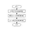
画像複雑さ指標計算部53aは、符号化部52の加算部52aから出力された減算信号Saに基づいて、各フレームの画像複雑さ指標を算出する。画像複雑さ指標は、分散、或いは、平均絶対値誤差で現され、各フレームの符号発生量と比例関係(或いは、何らかの関数、例えば、指数関数)にある。例えば、画像複雑さ指標として、Iピクチャでは分散を、Pピクチャ、Bピクチャでは差分画像の分散を、それぞれ使用する。画像複雑さ指標蓄積部53bは、画像複雑さ指標計算部53aで算出された画像複雑さ指標を蓄積する。そして、全てのフレームの画像複雑さ指標が算出された後、かかる画像複雑さ指標のデータが、画像複雑さ指標蓄積部53bからセレクタ53cを介して、符号割り当て計算部53dへ出力される。但し、第1回目のGOP内の各フレームの画像複雑さ指標は、画像複雑さ指標計算部53aにて計算できないため、予め、ある比率で設定した画像複雑さ指標を、シーケンス情報として、セレクタ53cから取り込み、符号割り当て計算部53dへ出力する。そして、符号割り当て計算部53dは、各フレームの画像複雑さ指標に基づいて、各フレームに最適な符号量を割り当てるための計算を行う。かかる計算は、図5に示すように、大きく3段階に分けることができる。第1の段階はGOP単位での符号発生量の補正、第2の段階は最初のフレームの符号発生量の補正、第3の段階はフレーム単位での符号発生量の補正である。
【0060】
(1)GOP単位での符号発生量の補正
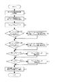
以下に、第1の段階のGOP単位での符号発生量の補正について、図6および図7を参照して説明する。図6は、符号割り当て計算部53dによるGOP単位での符号発生量の補正の処理を示すフローチャートを、図7は、GOP単位での符号発生量の補正におけるバッファ占有率(%)を示す図である。
【0061】
先ず、各フレームの画像複雑さ指標に基づいて、各GOPの目標符号発生量(bits)が算出される(S1)。例えば、目標総符号発生量(目標ビットレート(bps)×秒数(s))をT、総画像複雑さ指標をS、第i番目GOPの画像複雑さ指標をSGiとした場合、第i番目のGOPの目標符号発生量(TGi)は、式(数1)によって算出される。
【0062】
TGi=T・SGi/S (数1)
ここで、以降の説明に度々使用する画像複雑さ指標、目標符号発生量について、フレーム単位、GOP単位、総GOPで表した時の相互関係を図15に示しておく。
【0063】
次に、求められた各GOPの目標符号発生量(bits)に基づいて、各GOPの開始時点でのVBVバッファ占有率(%)(フレームデータ発生前)が算出される(S2)。例えば、VBVバッファサイズ(bits)をB、第i番目GOPのフレーム数をNGi、各フレーム毎のバッファの減少量(bits)をRとした場合、第i+1番目のGOPの開始時点でのVBVバッファ占有率(BLi+1,0)は、式(数2)によって算出される。
【0064】
BLi+1,0=BLi,0+(TGi−R・NGi)/B (数2)
但し、第1番目のGOPの開始時点でのVBVバッファ占有率(BLi,0)は、初期バッファ占有率(B0)に一致する。即ち、BLi,0=B0となる。
【0065】
こうして、全てのGOPの開始時点のVBVバッファ占有率(%)が算出されると、後述するオーバーフロー側のGOP補正比率(RGmax)が「1」に、アンダーフロー側のGOP補正比率(RGmin)が「1」に設定される(S3)。このRGmax、RGminは、GOP単位での符号発生量の補正にあたり使用されるパラメータであり、初期段階では「1」(即ち、補正無しを示す)に設定される。
【0066】
次に、GOPの開始時点のVBVバッファ占有率(%)が、予め設定されたVBVバッファ占有率(%)のGOP上限値(LUG)より大きいGOPがあるか否か(オーバーフローのGOPがあるか否か)が判断される(S4)。例えば、図7に示すように、第N−2番目のGOPの開始時点でのVBVバッファ占有率(BLN-2,0)が、VBVバッファ占有率(%)のGOP上限値(LUG)を超えた場合には、オーバーフローと判断される。そして、オーバーフローと判断されたGOPの全てについて(図7では、BLN-2,0のみであるが実際には、複数存在する)GOP補正比率(RGmax)が算出され、そのうち、最大のGOP補正比率(RGmax)が新たなGOP補正比率(RGmax)として設定される(S5)。初期バッファ占有率(%)をB0とすると、最大のGOP補正比率(RGmax)は、式(数3)によって算出される。
【0067】
RGmax=max((BLi,0−B0)/(LUG−B0)) (数3)
次に、上記GOPの開始時点のVBVバッファ占有率(%)が、予め設定されたVBVバッファ占有率(%)のGOP下限値(LLG)より小さいGOPがあるか否か(アンダーフローのGOPがあるか否か)が判断される(S6)。例えば、図7に示すように、第3番目のGOPの開始時点でのVBVバッファ占有率(BL3,0)が、VBVバッファ占有率(%)のGOP下限値(LLG)を下回った場合には、アンダーフローと判断される。そして、アンダーフローと判断されたGOPの全てについて、GOP補正比率(RGmin)が算出され、そのうち、最大のGOP補正比率(RGmin)が新たなGOP補正比率(RGmin)として設定される(S7)。最大のGOP補正比率(RGmin)は、式(数4)によって算出される。
【0068】
RGmin=max((BLi,0−B0)/(LLG−B0)) (数4)
ここで、GOP上限値(LUG)およびGOP下限値(LLG)は、実際の符号発生量とのズレを見込んで任意に設定することができる。
【0069】
次に、各GOPの開始時点のVBVバッファ占有率(%)について、初期バッファ占有率(B0)より大きいか否かが判断される(S8)。初期バッファ占有率(B0)より大きいと判断されたGOPについては、そのGOPの開始時点のVBVバッファ占有率(%)が、ステップS5で算出された補正比率(RGmax)に基づいて補正される(S9)。即ち、図7に示すように、当該GOP内の全てのフレームのバッファ占有率(%)が、補正比率(RGmax)に基づいて、一律に低下(図7の例では、実線のバッファ占有率(%)から破線のバッファ占有率(%)に補正)されることとなる。例えば、ステップS9による補正後の第i番目のVBVバッファ占有率(BL’i,0)は、式(数5)によって算出される。
【0070】
BL’i,0=B0+(BLi,0−B0)/RGmax (数5)
次に、各GOPの開始時点のVBVバッファ占有率(%)について、初期バッファ占有率(B0)より小さいか否かが判断される(S10)。初期バッファ占有率(B0)より小さいと判断されたGOPについては、そのGOPの開始時点のVBVバッファ占有率(%)が、ステップS7で算出された補正比率(RGmin)に基づいて補正される(S11)。かかる補正では、当該GOP内の全てのフレームのバッファ占有率(%)が、補正比率(RGmin)に基づいて、一律に上昇されることとなる。例えば、ステップS11による補正後の第i番目のVBVバッファ占有率(BL’i,0)は、式(数6)によって算出される。
【0071】
BL’i,0=B0+(BLi,0−B0)/RGmin (数6)
こうして、各GOPの開始時点のVBVバッファ占有率(%)の補正が行われると、これらの補正結果による各GOPの割り当て符号量が算出される(S12)。例えば、第i番目GOPのフレーム数をNGi、各フレーム毎のVBVバッファの減少量(bits)をRとした場合、第i番目のGOPの割り当て符号量(TG’i)は、式(数7)によって算出される。
【0072】
TG’i=R・NGi+(BLi+1,0−BLi,0)・B (数7)
ここで、BLi+1,0、BLi,0には、ステップS7、若しくはステップS9にて補正されたものは補正後のBL’i+1,0、BL’i,0を、補正されていないものはステップS3で算出されたBLi+1,0、BLi,0を使用する。
【0073】
このように、第1の段階では、GOP単位での符号発生量の補正を行い、各GOPに符号量が割り当てられる。これにより、先ず、GOP単位で、オーバーフロー、アンダーフローの発生を極力抑えることができる。
【0074】
なお、符号化するシーケンスがGOP構造を持たず、かつ、シーケンスが短い場合には、全体を1つのGOPとみなし、上記処理をスキップするように構成する。また、符号化するシーケンスがGOP構造を持たず、かつ、シーケンスが長い場合には、全体を複数のシーケンスに分割し、それぞれをGOPとみなして上記処理を行うように構成する。
【0075】
(2)最初のフレームの符号発生量の補正
上記第1の段階の補正では、GOP内の各フレーム毎のVBVバッファ占有率(%)は考慮せず、GOP単位でVBVバッファ占有率(%)を考慮して割り当てる符号量を決定したため、GOP内のフレームのバッファ占有率(%)が、予め設定されたVBVバッファ占有率(%)のフレーム上限値(LUF)より大きくなったり、或いは、VBVバッファ占有率(%)のフレーム下限値(LLF)より小さくなったりする場合がある。かかる場合に、この第2の段階では、最初のフレームの符号発生量を補正し、最初のフレームに最適な符号量を割り当てるものである。そして、最初のフレーム以外のフレームの符号発生量の補正は、第3の段階で行う。
【0076】
以下に、第2の段階の最初のフレームの符号発生量の補正について、図8および図9を参照して説明する。図8は、符号割り当て計算部53dによる最初のフレームの符号発生量の補正の処理を示すフローチャートを、図9は、最初のフレームの符号発生量の補正におけるバッファ占有率(%)を示す図である。
【0077】
先ず、GOPの目標符号発生量(bits)と、最初のフレームの画像複雑さ指標とGOPの画像複雑さ指標との比より、GOPの最初のフレームの目標符号発生量(bits)が算出される(S21)。例えば、第i番目GOPの最初のフレームの画像複雑さ指標をSFi,0、第i番目GOPの画像複雑さ指標をSGiとした場合、第i番目のGOPの最初のフレームの目標符号発生量(bits)(TFi,0)は、式(数8)によって算出される。
【0078】
TFi,0=TGi・SFi,0/SGi (数8)
次に、求められたGOPの開始時点のVBVバッファ占有率(%)に基づいて、その最初のフレームのVBVバッファ占有率(%)(例えば、i番目GOPの最初のフレームのVBVバッファ占有率BUi,0)が式(数9)によって算出される(S22)。
【0079】
BUi,0=BLi,0+TFi,0/B (数9)
次に、かかる最初のフレームのVBVバッファ占有率(%)が、予め設定されたVBVバッファ占有率(%)のフレーム上限値(LUF)より大きいか否か(オーバーフローしているか否か)が判断される(S23)。フレーム上限値(LUF)より大きいと判断された場合、最初のフレームのVBVバッファ占有率(%)が補正される(S24)。例えば、補正後の第i番目のGOPの最初のフレームのバッファ占有率(BU’i,0)は、式(数10)によって算出される。
【0080】
BU’i,0=LUF (数10)
図9の例では、最初のフレームのVBVバッファ占有率(BUi,0)から、フレーム上限値(LUF)を超えた分(X)が差し引かれ、新たなVBVバッファ占有率(BU’i,0)として設定されることを示している。この差し引かれた「X」分の符号量、即ち、本来、最初のフレームに割り当てるべき符号量は、後述する第3の段階の補正にて、後のフレーム(同じGOP内の最初のフレーム以外のフレーム)に補填(比例配分)することとなる。
【0081】
次に、GOPの最初のフレームのVBVバッファ占有率(%)が、予め設定されたVBVバッファ占有率(%)のフレーム下限値(LLF)より小さいか否か(アンダーフローしているか否か)が判断される(S25)。フレーム下限値(LLF)より小さいと判断された場合、最初のフレームのVBVバッファ占有率(%)が補正される(S26)。例えば、補正後の第i番目のGOPの最初のフレームのバッファ占有率(BU’i,0)は、式(数11)によって算出される。
【0082】
BU’i,0=LLF (数11)
ここで、フレーム上限値(LUF)およびフレーム下限値(LLF)は、実際の符号発生量とのズレを見込んで任意に設定することができる。
【0083】
こうして、GOPの最初のフレームのVBVバッファ占有率(%)の補正が行われると、これらの補正結果によるGOPの最初のフレームの割り当て符号量が算出される(S27)。例えば、第i番目のGOPの最初のフレームの割り当て符号量(TF’i,0)は、式(数12)によって算出される。
【0084】
TF’i,0=(BUi,0−BLi,0)・B (数12)
ここで、BUi,0には、ステップS24、若しくはステップS26にて補正されたものは補正後のBU’i,0を、補正されていないものはステップS22で算出されたBUi,0を使用する。
【0085】
なお、最初のフレームの符号発生量の補正は、符号化するシーケンス内の全てのGOPが対象となる。
【0086】
このように、第2の段階では、GOP内の最初のフレームの符号発生量の補正を行い、最初のフレームに最適な符号量が割り当てられる。これにより、最初のフレームの符号量が確定し、これを基準に第3の段階にて、最初のフレーム以外のフレームの符号発生量の補正を行うことができる。このように、最初のフレームの発生符号量を、先ず始めに補正することとしたのは、上述した通り、GOPは、通常、Iピクチャの後に、Pピクチャ、Bピクチャがくるような構造となっており、Pピクチャ、Bピクチャは、Iピクチャのフレームを参照して予測していくものであるため、綺麗な画像を得るには、なるべく、最初のフレームであるIピクチャの符号発生量を維持する必要があるからである。即ち、第2の段階で、最初のフレームのVBVバッファ占有率がオーバーフローにならない場合には、最初のフレームたるIピクチャの符号発生量はそのまま維持され、その後の第3の段階にて補正されない。また、第2の段階で、最初のフレームのVBVバッファ占有率がオーバーフローになる場合にも、最初のフレームであるIピクチャの符号発生量は最小限の補正にとどまり、その後の第3の段階にて補正されないので、綺麗な画像を確保できるのである。
【0087】
(3)フレーム単位での符号発生量の補正
第2の段階の補正では、GOPの最初のフレームの符号発生量を補正し、最適な符号量の割り当てを行なったが、この第3の段階の補正では、最初のフレーム以外のフレームの符号発生量を補正し、最適な符号量の割り当てを行うものである。
【0088】
以下に、第3の段階のフレーム単位での符号発生量の補正について、図10および図11を参照して説明する。図10は、符号割り当て計算部53dによるフレーム単位での符号発生量の補正の処理を示すフローチャートを、図11は、フレーム単位での符号発生量の補正におけるバッファ占有率(%)を示す図である。
【0089】
先ず、GOP内の最初のフレーム以外の各フレームの目標符号発生量(bits)が、各フレームの画像複雑さ指標に基づいて算出される(S31)。各フレームの目標符号発生量(bits)は、GOPに割り当てられた符号量から最初のフレームの符号量を差し引いたものを、画像複雑さ指標で比例配分して算出される。例えば、t=TGi−TFi,0とし、s=SGi−SFi,0とすると、第i番目GOPの第j番目フレームの目標符号発生量(bits)(TFi,j)は、式(数13)によって算出される。
【0090】
TFi,j=t・SFi,j/s (数13)
次に、求められたGOPのフレームの目標符号発生量(bits)に基づいて、フレームデータ発生前と、発生後のVBVバッファ占有率(%)が算出される(S32)。例えば、VBVバッファサイズ(bits)をBとした場合、第i番目GOPの第j番目フレームのデータ発生後のVBVバッファ占有率(BUi,j)は、式(数14)によって算出される。
【0091】
BUi,j=BLi,j+TFi,j/B (数14)
また、式(数13)の「BLi,j」は、第i番目GOPの第j番目フレームのデータ発生前のVBVバッファ占有率(%)を示しており、例えば、式(数15)によって算出される。
【0092】
BLi,j+1=BUi,j−R/B (数15)
こうして、図11に示すBUi,j、BLi,jが算出されると、オーバーフロー側のフレーム補正比率(RFmax)が「1」に、アンダーフロー側のフレーム補正比率(RFmin)が「1」に設定される(S33)。このRFmax、RFminは、フレーム単位での符号発生量の補正にあたり使用されるパラメータであり、初期段階では、「1」(即ち、補正無しを示す)に設定される。
【0093】
次に、図11(A)に示すように、一つのGOP内の最初のフレームのバッファ占有率(%)と、最後のフレームバッファ占有率(%)の間の目標(理想)ラインの値が、算出される(S34)。例えば、第i番目GOPの最初のフレームのVBVバッファ占有率をBUi,0と、第i番目GOPの最後のフレーム(第i番目GOPのフレーム総数(NGi)−1)のVBVバッファ占有率をBUi,NGi-1、とすると、第i番目GOPの第j番目のフレームの目標ラインの値(Kj)は、式(数16)によって算出される。
【0094】
Kj=BUi,0+(BUi,NGi-1−BUi,0)・j/(NGi−1) (数16)
次に、ステップS32で算出されたフレームのデータ発生後のVBVバッファ占有率(%)が、予め設定されたVBVバッファ占有率(%)のフレーム上限値(LUF)より大きいフレームがあるか否か(オーバーフローのフレームがあるか否か)が判断される(S35)。オーバーフローと判断されたフレームの全てについて、フレーム補正比率(RFmax)が算出され、そのうち、最大のフレーム補正比率(RFmax)が新たなフレーム補正比率(RFmax)として設定される(S36)。最大のフレーム補正比率(RFmax)は、式(数17)によって算出される。
【0095】
RFmax=max((BUi,j−Kj)/(LUF−Kj)) (数17)
次に、ステップS32で算出されたフレームのデータ発生前のVBVバッファ占有率(%)が、予め設定されたVBVバッファ占有率(%)のフレーム下限値(LLF)より小さいフレームがあるか否か(アンダーフローのフレームがあるか否か)が判断される(S37)。アンダーフローと判断されたフレームの全てについて、フレーム補正比率(RFmin)が算出され、そのうち、最大のフレーム補正比率(RFmin)が新たなフレーム補正比率(RFmin)として設定される(S38)。最大のフレーム補正比率(RFmin)は、式(数18)によって算出される。
【0096】
RFmin=max((Kj−BLi,j)/(Kj−LLF)) (数18)
図11(A)では、第i番目GOPの第j番目フレームがアンダーフローを起こしているが、式(数17)の「(Kj−BLi,j)/(Kj−LLF)」は、図11(B)の「a/b」に相当する。同じGOP内のフレームの「a/b」(アンダーフローを起こしているフレームに限る。)のうち、最も大きい値がRFminとして設定される。
【0097】
次に、一つのフレームのデータ発生後のVBVバッファ占有率(%)が目標ラインの値(Kj)より大きく、かつ、そのフレームの次のフレームのデータ発生前のVBVバッファ占有率(%)も目標ラインの値(Kj)より大きいという条件を満たすその一つのフレームがあるか否かが判断される(S39)。例えば、BUi,j>Kj、かつ、BLi,j+1>Kj+1の条件を満たす第j番目のフレームがあるか否か判断される。そのようなフレームがあると判断された場合には、そのフレームのデータ発生後のVBVバッファ占有率(%)が、ステップS36で算出されたフレーム補正比率(RFmax)に基づいて補正される(S40)。例えば、そのようなフレームが第j番目フレームであるとすると、補正後の第j番目フレームのデータ発生後のVBVバッファ占有率(BU’i,j)は、式(数19)によって算出される。
【0098】
BU’i,j=Kj+(BUi,j−Kj)/RFmax (数19)
このような補正は、上記条件を満たす全てのフレームについて行われる。
【0099】
次に、一つのフレームのデータ発生後のVBVバッファ占有率(%)が目標ラインの値(Kj)より小さく、かつ、そのフレームの次のフレームのデータ発生前のVBVバッファ占有率(%)も目標ラインの値(Kj)より小さいという条件を満たすその一つのフレームがあるか否かが判断される(S41)。例えば、BUi,j<Kj、かつ、BLi,j+1<Kj+1の条件を満たす第j番目のフレームがあるか否か判断される。そのようなフレームがあると判断された場合には、そのフレームの次のフレームのデータ発生前のVBVバッファ占有率(%)が、ステップS38で算出されたフレーム補正比率(RFmin)に基づいて補正される(S42)。例えば、そのようなフレームが第j番目フレームであるとすると、補正後の第j+1番目フレームのデータ発生前のVBVバッファ占有率(BL’i,j+1)は、式(数20)によって算出される。
【0100】
BL’i,j+1=Kj+1−(Kj+1−BLi,j+1)/RFmin (数20)
即ち、図11(C)に示すように、最初のフレーム以外のフレームのVBVバッファ占有率(%)がRFmin=b/aで比例補正される。
【0101】
また、BU’i,jとBL’i,j+1との関係は、式(数21)で表される。
【0102】
BU’i,j=BL’i,j+1+R/B (数21)
なお、図10に示す処理は、シーケンス内の全てのGOPについて行われるが、ステップ35にてオーバーフローのフレームもなく、ステップS37にてアンダーフローのフレームもないと判断されたGOPについては、上記補正は行われないこととなる。
【0103】
こうして、GOPの最初のフレーム以外のフレームのVBVバッファ占有率(%)の補正が行われると、これらの補正結果によるGOPの最初のフレーム以外のフレームの割り当て符号量が算出される(S43)。例えば、第i番目GOPのj番目フレームの割り当て符号量(TF’i,j)は、式(数22)によって算出される。
【0104】
TF’i,j=R+(BLi,j+1−BLi,j)・B=R+(BUi,j−BUi,j-1)・B (数22)
ここで、BLi,j+1、BLi,jには、ステップS42にて補正されたものは補正後のBL’i,j+1、BL’i,jを、補正されていないものはステップS32で算出されたBLi,j+1、BLi,jを使用する。また、BUi,j、BUi,j-1には、ステップS40にて補正されたものは補正後のBU’i,j、BU’i,j-1を、補正されていないものはステップS32で算出されたBUi,j、BUi,j-1を使用する。
【0105】
このように、第3の段階では、フレーム単位での符号発生量の補正を行い、各フレーム(最初のフレームを除く)に最適な符号量が割り当てられる。これにより、各フレーム単位のオーバーフロー、アンダーフローを完全に無くすことができる。
【0106】
以上の説明したように、符号割り当て計算部53dは、上記3段階の補正を行い、最適な符号量の割り当てを行なった後、かかる符号量をレート信号Srとして、量子化制御部55へ出力する。そして、上述した通り、符号化部52は、変換信号Sdを量子化制御部55からのレート信号Srに基づいて決定される量子化スケールで量子化して、ビデオ・ストリームを作成して出力する。
【0107】
このように作成されたビデオ・ストリームにより、MPEGデコーダでデコードされる際、オーバーフロー、アンダーフローを発生させずに、かつ、高画質の画像を再生させることができる。
【0108】
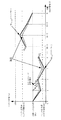
図12乃至図14は、上記補正のシミュレーション結果を示すものである。図12は、補正前と後のVBVバッファ占有率(%)および割り当て符号量(bits)をGOP単位で示したものである。図12に示すように、補正前のバッファ占有率55は、バッファ占有率のGOP上限値(LUG=75%)とバッファ占有率のGOP下限値(LLG=15%)の範囲内に無いGOPが存在し、オーバーフロー、アンダーフローを起こしているが、補正後のバッファ占有率56は、かかる範囲内に収まっていることがわかる。また、図13は、補正前と後のVBVバッファ占有率(%)および割り当て符号量(bits)をフレーム単位で示したものであり、オーバーフロー側の補正に関するものである。図14は、補正前と後のVBVバッファ占有率(%)および割り当て符号量(bits)をフレーム単位で示したものであり、アンダーフロー側の補正に関するものである。図13および図14を合わせて見ると、補正前のバッファ占有率60は、図13に示すバッファ占有率のフレーム上限値(LUF=85%)と、図14に示すバッファ占有率のフレーム下限値(LLG=15%)の範囲内に無いフレームが存在し、オーバーフロー、アンダーフローを起こしているが、補正後のバッファ占有率61は、かかる範囲内に収まっていることがわかる。また、かかる補正は、上述した通り、理想ライン62を中心に補正されていることがわかる。
【0109】
なお、上記実施形態においては、上記3段階の補正を行い、最適な符号量を割り当てることとしたが、これに限定されず、例えば、上記第1の段階の補正(GOP単位での符号発生量の補正)のみを行って、最適な符号量を割り当てるようにしてもよく、或いは、上記第2の段階の補正(最初のフレームの符号発生量の補正)および上記第3の段階の補正(フレーム単位での符号発生量の補正)のみを行って、最適な符号量を割り当てるようにしてもよい。
【0110】
また、上記実施形態において、Iピクチャ、Pピクチャ、Bピクチャ、GOPの名称は、MPEG−1、MPEG−2における呼び名であるが、MPEG−4の場合には、IピクチャをI−VOP(Video Object Plane)、PピクチャをP−VOP、BピクチャをB−VOP、GOPをGOV(Group Of VOP)と読み替えることで、同様の機能を実現できる。所定数の画像フレームを有する画像群には、GOVも含まれる。
【0111】
【発明の効果】
以上説明したように、本発明によれば、ビデオ・シーケンスを構成する、各画像群、各フレームの画像複雑さ指標に基づいて算出された符号発生量に対して3段階の補正を行うことにより、オーバーフロー、アンダーフローが発生しない最適な符号量を割り当てることができる。また、最初のフレームの発生符号量の補正は最小限にとどめ、出来る限り最初のフレームの符号発生量を維持することができるので、より綺麗な画像を確保できる。
【図面の簡単な説明】
【図1】本発明の実施形態にかかるMPEGデコーダの理想(仮想)モデルを示す図である。
【図2】本発明の実施形態にかかるVBVバッファのデータ占有量(bits)の推移状況を示す図である。
【図3】図2において、オーバーフロー、アンダーフローがある場合のVBVバッファのデータ占有量(bits)の推移状況を示す図である。
【図4】本発明の実施形態にかかるMPEGエンコーダ100の概略構成図である。
【図5】本発明の実施形態にかかる符号発生量の補正処理を示すフローチャートである。
【図6】本発明の実施形態にかかる符号割り当て計算部によるGOP単位での符号発生量の補正の処理を示すフローチャートである。
【図7】GOP単位での符号発生量の補正におけるバッファ占有率(%)を示す図である。
【図8】本発明の実施形態にかかる符号割り当て計算部による最初のフレームの符号発生量の補正の処理を示すフローチャートである。
【図9】最初のフレームの符号発生量の補正におけるバッファ占有率(%)を示す図である。
【図10】本発明の実施形態にかかる符号割り当て計算部によるフレーム単位での符号発生量の補正の処理を示すフローチャートである。
【図11】フレーム単位での符号発生量の補正におけるバッファ占有率(%)を示す図である。
【図12】補正前と後のVBVバッファ占有率(%)および割り当て符号量(bits)をGOP単位で示した図である。
【図13】補正前と後のVBVバッファ占有率(%)および割り当て符号量(bits)をフレーム単位で示したものであり、オーバーフロー側の補正に関する図である。
【図14】補正前と後のVBVバッファ占有率(%)および割り当て符号量(bits)をフレーム単位で示したものであり、アンダーフロー側の補正に関する図である。
【図15】画像複雑さ指標、目標符号発生量について、フレーム単位、GOP単位、総GOPで表した時の相互関係を示す図である。
【符号の説明】
10…VBVバッファ
20…MPEGデコーダ
30…整列用バッファ
50…取得部
51…動き検出部
52…符号化部
52a…加算部
52b…離散コサイン変換部
52c…量子化部
52d…可変長符号化部
52e…逆量子化部
52f…逆離散コサイン変換部
52g…フレーム蓄積および補償予測部
53…最適符号量計算部
53a…画像複雑さ指標計算部
53b…画像複雑さ指標蓄積部
53c…セレクタ
53d…符号量割り当て計算部
54…発生符号量計算部
55…量子化計算部
56…マルチプレクサ
57…バッファメモリ[0001]
BACKGROUND OF THE INVENTION
The present invention relates to an apparatus and method for assigning a code amount in compressed encoded data recording in which a video signal is encoded and recorded on a recording medium.
[0002]
[Prior art]
Usually, when an image is digitized and recorded on a recording medium such as a DVD-ROM, a CD-ROM, or a hard disk, the amount of data becomes enormous. This compression encoding method includes various compression encoding methods, and in particular, an encoding method based on DCT (Discrete Cosine Transform) that performs compression using the property that the spatial frequency of an image is concentrated at a low frequency. However, it is used relatively frequently. DCT is used in international standard encoding schemes such as JPEG (Joint Photographic Coding Experts Group), MPEG (Moving Picture Coding Experts Group) 1, MPEG2 or MPEG4.
[0003]
2. Description of the Related Art Conventionally, it is known that an apparatus that performs compression coding using the MPEG method performs coding control using a fixed bit rate coding method or a variable bit rate coding method.
[0004]
In the fixed bit rate encoding method, the target code amount of each frame constituting the video sequence is a constant value regardless of the complexity of the image, and the occupancy rate of the decoder buffer is taken into consideration at the time of encoding, Encoding control is performed so that overflow and underflow do not occur.
[0005]
On the other hand, in the variable bit rate coding method, since the optimal code amount allocation of each frame in the video sequence is performed in advance based on the image complexity index obtained in advance, it is required for each frame. A code amount can be allocated, and a difference in image quality between frames can be suppressed.
[0006]
[Problems to be solved by the invention]
By the way, since the code generation amount of each frame has a correlation with the image complexity index of the frame, when the code amount allocation of each frame ignoring the image complexity index, the image quality of each frame is uneven. . In addition, in the code amount allocation considering the occupancy rate of the decoder / buffer at the time of encoding, when a larger amount of code is desired, there is little room for the buffer, so a large code amount cannot be allocated and image quality degradation occurs. Even when a sufficient amount of image quality can be obtained with a small code amount, a large amount of code is allocated due to a large buffer space.
[0007]
On the other hand, if the code amount allocation for each frame is simply performed based on the image complexity index, the decoder buffer will cause an overflow or underflow.
[0008]
The present invention has been made in view of the above points, and provides an apparatus and a method for allocating an optimal code amount to each frame based on an image complexity index of each frame constituting a video sequence. Objective.
[0009]
[Means for Solving the Problems]
In order to solve the above-described problem, the invention described in
[0010]
According to the invention thus configured, a plurality of predetermined number of image frames included in the video signal.A target code generation amount of each image group is obtained based on an image complexity index of each image group, and a buffer occupancy rate of each image group and before the data generation of the frame is calculated . Next, the buffer occupancy of the image group is corrected so that the calculated buffer occupancy of the image group falls within a range between a preset upper limit and lower limit of the buffer occupancy, A code amount is assigned for each image group (first stage). Next, the target code generation amount of the first frame in the image group to which the code amount is assigned is obtained based on the image complexity index of each first frame, and after the data generation of each first frame The buffer occupancy is calculated. Next, the buffer occupancy of the first frame is corrected so that the calculated buffer occupancy of the first frame does not exceed the preset upper limit of the buffer occupancy, and the first frame is encoded. An amount is assigned (second stage). Next, a target code generation amount of a frame other than the first frame in the image group to which the code amount is assigned is obtained based on an image complexity index of each frame, and a buffer after data generation of each frame is generated. The occupation rate is calculated. The buffer occupancy of the frames other than the first frame is set so that the buffer occupancy of the frames other than the calculated first frame falls within a predetermined range between the upper limit value and the lower limit value of the buffer occupancy rate. The rate is corrected and a code amount is assigned to the frame (third stage).
[0011]
Therefore,The code generation amount obtained based on the image complexity index is corrected in three stages (correction of buffer occupancy for each image group, correction of buffer occupancy for the first frame, buffer occupancy for frames other than the first frame) Therefore, an optimal code amount without overflow or underflow can be assigned to each frame in the decoder buffer, and higher image quality can be realized. Also, in the second stage, prior to the third stage, by assigning the code amount of the first frame, the generated code amount of the first frame can be maintained as much as possible, so that a more beautiful image is reproduced. be able to.
[0012]
The invention described in claim 2In the code amount allocation apparatus according to
[0013]
The invention according to claim 3In the code amount allocation apparatus according to
[0014]
According to a fifth aspect of the present invention, there is provided a code amount allocating apparatus in compression encoded data recording for encoding a video signal and recording the encoded video signal on a recording medium, and an image group having a plurality of predetermined number of image frames included in the video signal Image group buffer occupancy calculation for determining the target code generation amount of each image group based on the image complexity index of each image group and calculating the buffer occupancy ratio of each image group before the frame data is generated Means for correcting the buffer occupancy of the image group such that the calculated buffer occupancy of the image group falls within a range between a preset upper limit and lower limit of the buffer occupancy; Image group code amount assigning means for assigning a code amount in units of the image group, and a target code generation amount of the first frame in the image group to which the code amount is assigned, First frame buffer occupancy calculating means for calculating a buffer occupancy after data generation of each first frame is obtained based on the image complexity index of the frame, and the calculated buffer occupancy of the first frame is: First frame code amount allocating means for correcting the buffer occupancy rate of the first frame so as not to exceed a preset upper limit value of the buffer occupancy rate and allocating a code amount to the first frame; and A second frame for calculating a target code generation amount of a frame other than the first frame in the allocated image group based on an image complexity index of each frame and calculating a buffer occupancy after data generation of each frame The buffer occupancy rate calculation means and the buffer occupancy rate of frames other than the calculated first frame are preset. Second frame code amount allocating means for correcting a buffer occupancy rate of a frame other than the first frame and allocating a code amount to the frame so as to be within a range between the upper limit value and the lower limit value of the buffer occupancy rate And the second frame code amount allocating means determines whether or not a buffer occupancy rate of a frame other than the calculated first frame is larger than a preset upper limit value of the buffer occupancy rate, and It is determined whether the buffer occupancy rate is smaller than a lower limit of the set buffer occupancy rate, the buffer occupancy rate of the frame larger than the upper limit value or the buffer occupancy rate of the frame smaller than the lower limit value, and a line obtained in advance. A buffer occupancy ratio of a first frame to which a code amount is allocated by the first frame code amount allocation means, and an image group having the first frame And calculating the first difference from the buffer occupancy on the ideal line drawn between the buffer occupancy of the last frame and the upper limit or lower limit of the buffer occupancy and the previously obtained A second difference from the buffer occupancy on the ideal line is calculated, a ratio between the first difference and the second difference is calculated as a frame correction ratio, and the largest of the calculated frame correction ratios A frame correction ratio is obtained for each of the upper limit value and the lower limit value, the frame correction ratio is corrected by multiplying the buffer occupancy ratio of a frame other than the first frame, and a code amount is assigned to the frame.Configure as follows.
[0015]
The invention according to
[0016]
The invention described in claim 7In the code amount allocation method according to
[0017]
The invention according to
[0018]
The invention according to
[0043]
DETAILED DESCRIPTION OF THE INVENTION
Preferred embodiments of the present invention will be described below with reference to the drawings.
[0044]
In the embodiment described below, an optimal code for each frame is used in a code amount allocation apparatus (hereinafter referred to as “MPEG encoder”) in compressed encoded data recording in which a video signal is encoded by the MPEG method and recorded on a recording medium. This is an embodiment in the case where the present invention is applied with respect to allocation of a large amount of code. Note that the recording medium includes a DVD-ROM, a DVD-RAM, a DVD-RW, a CD-ROM, a hard disk, and the like.
[0045]
Before specifically describing the embodiment of the present invention, a video sequence (hereinafter referred to as a “bit stream (encoded data sequence)”) created by an MPEG encoder and recorded on a recording medium is converted into an MPEG. A flow when decoding is performed by a decoding apparatus (hereinafter referred to as an “MPEG decoder”) that performs decoding by a method will be described with reference to FIGS. 1 and 2. FIG. 1 is a diagram showing an ideal (virtual) model (STD: System Target Decoder) of an MPEG decoder. This ideal model includes a VBV (Video Buffer Verifier)
[0046]
As shown in FIG. 1, the bit stream created by the MPEG encoder is input to the
[0047]
Next, the bit stream input to the
[0048]
Next, one frame of data transferred to the
[0049]
In this way, the input bit stream is decoded (decoded) by the
[0050]
Hereinafter, an embodiment of the present invention will be described in detail with reference to FIGS. 4 to 14 regarding the optimum code amount allocation to each frame in the MPEG encoder.
[0051]
FIG. 4 is a schematic configuration diagram of the
[0052]
First, the operation of the
[0053]
The acquisition unit 50 acquires image data from the input digital video signal for each frame and performs predetermined processing such as field thinning. Also, the picture type of the acquired frame is determined, and if the frame order needs to be changed, for example, if it is a B picture, the frame order is also changed. The motion detection unit 51 calculates a motion vector of the input image in units of 16 × 16 pixel macroblocks and outputs the motion vector as a frame signal Sv.
[0054]
The encoder 52 includes an
[0055]
The
[0056]
The
[0057]
On the other hand, the variable length coding unit 52d performs variable length coding processing on the quantized signal Sq, and outputs the result to the buffer memory 57 via the
[0058]
Next, an optimal code generation amount allocation process for each frame, which is a feature of the present invention, will be described. Such processing is performed by the optimum code
[0059]
The image complexity
[0060]
(1) Correction of code generation amount in GOP units
Hereinafter, the correction of the code generation amount in GOP units in the first stage will be described with reference to FIG. 6 and FIG. FIG. 6 is a flowchart showing the process of correcting the code generation amount in GOP units by the code allocation calculation unit 53d, and FIG. 7 is a diagram showing the buffer occupancy rate (%) in the correction of the code generation amount in GOP units. is there.
[0061]
First, the target code generation amount (bits) of each GOP is calculated based on the image complexity index of each frame (S1). For example, T is the target total code generation amount (target bit rate (bps) × seconds (s)), S is the total image complexity index, and SG is the image complexity index of the i-th GOP.iIn this case, the target code generation amount (TG) of the i-th GOPi) Is calculated by the equation (Equation 1).
[0062]
TGi= T ・ SGi/ S (Equation 1)
Here, FIG. 15 shows the interrelationship between the image complexity index and the target code generation amount that are frequently used in the following description, expressed in frame units, GOP units, and total GOPs.
[0063]
Next, based on the obtained target code generation amount (bits) of each GOP, the VBV buffer occupancy (%) (before generation of frame data) at the start time of each GOP is calculated (S2). For example, the VBV buffer size (bits) is B and the number of frames of the i-th GOP is NG.iWhen the buffer reduction amount (bits) for each frame is R, the VBV buffer occupancy rate (BL at the start time of the (i + 1) th GOPi + 1,0) Is calculated by the equation (Equation 2).
[0064]
BLi + 1,0= BLi, 0+ (TGi-R ・ NGi) / B (Equation 2)
However, the VBV buffer occupancy at the start of the first GOP (BLi, 0) Is the initial buffer occupancy (B0). That is, BLi, 0= B0It becomes.
[0065]
When the VBV buffer occupancy (%) at the start of all GOPs is calculated in this way, an overflow side GOP correction ratio (RGmax) To “1”, GOP correction ratio (RG on the underflow side)min) Is set to "1" (S3). This RGmax, RGminIs a parameter used for correcting the amount of generated code in units of GOP, and is set to “1” (that is, no correction) in the initial stage.
[0066]
Next, whether or not there is a GOP whose VBV buffer occupancy rate (%) at the start of GOP is larger than the preset GOP upper limit value (LUG) of VBV buffer occupancy rate (%) (whether there is an overflow GOP) No) is determined (S4). For example, as shown in FIG. 7, the VBV buffer occupancy rate (BLN-2,0) Exceeds the GOP upper limit value (LUG) of the VBV buffer occupancy rate (%), it is determined as an overflow. For all GOPs that are determined to be overflow (in FIG. 7, BLN-2,0But there are actually multiple) GOP correction ratios (RGmax) Of which the maximum GOP correction ratio (RG)max) Is the new GOP correction ratio (RGmax) Is set (S5). Set the initial buffer occupancy (%) to B0Then, the maximum GOP correction ratio (RGmax) Is calculated by the equation (Equation 3).
[0067]
RGmax= Max ((BLi, 0-B0) / (LUG-B0)) (Equation 3)
Next, whether or not there is a GOP whose VBV buffer occupancy rate (%) at the start of the GOP is smaller than the preset GOP lower limit value (LLG) of the VBV buffer occupancy rate (%) (underflow GOP is Is determined) (S6). For example, as shown in FIG. 7, the VBV buffer occupancy (BL3,0) Falls below the GOP lower limit (LLG) of the VBV buffer occupancy (%), it is determined that the underflow has occurred. The GOP correction ratio (RG) is used for all GOPs that are determined to be underflowed.min) Of which the maximum GOP correction ratio (RG)min) Is the new GOP correction ratio (RGmin) Is set (S7). Maximum GOP correction ratio (RGmin) Is calculated by the equation (Equation 4).
[0068]
RGmin= Max ((BLi, 0-B0) / (LLG-B0)) (Equation 4)
Here, the GOP upper limit value (LUG) and the GOP lower limit value (LLG) can be arbitrarily set in view of a deviation from the actual code generation amount.
[0069]
Next, for the VBV buffer occupancy (%) at the start of each GOP, the initial buffer occupancy (B0) Is determined (S8). Initial buffer occupancy (B0For a GOP determined to be larger than the GOP, the VBV buffer occupancy rate (%) at the start of the GOP is the correction ratio (RG) calculated in step S5.max) Is corrected based on (). That is, as shown in FIG. 7, the buffer occupancy rate (%) of all frames in the GOP is calculated as a correction ratio (RG).max), It is uniformly reduced (in the example of FIG. 7, the buffer occupancy rate (%) of the solid line is corrected to the buffer occupancy rate (%) of the broken line). For example, the i-th VBV buffer occupation rate (BL ′ after correction in step S9)i, 0) Is calculated by the equation (Equation 5).
[0070]
BL ’i, 0= B0+ (BLi, 0-B0) / RGmax (Equation 5)
Next, for the VBV buffer occupancy (%) at the start of each GOP, the initial buffer occupancy (B0It is determined whether it is smaller than (S10). Initial buffer occupancy (B0For the GOP determined to be smaller than the GOP, the VBV buffer occupancy (%) at the start of the GOP is the correction ratio (RG) calculated in step S7.min) Is corrected based on (). In such correction, the buffer occupancy rate (%) of all frames in the GOP is changed to the correction ratio (RGmin) Will be raised uniformly. For example, the i-th VBV buffer occupation rate (BL ′ after correction in step S11)i, 0) Is calculated by the equation (Equation 6).
[0071]
BL ’i, 0= B0+ (BLi, 0-B0) / RGmin (Equation 6)
When the VBV buffer occupancy (%) at the start time of each GOP is corrected in this way, the allocated code amount of each GOP based on these correction results is calculated (S12). For example, if the number of frames of the i-th GOP is NGiWhen the amount of reduction (bits) of the VBV buffer for each frame is R, the allocated code amount (TG ′) of the i-th GOPi) Is calculated by the equation (Equation 7).
[0072]
TG ’i= R ・ NGi+ (BLi + 1,0-BLi, 0) ・ B (Equation 7)
Where BLi + 1,0, BLi, 0In step S7 or S9, the corrected BL 'is the corrected BL'.i + 1,0, BL ’i, 0For those not corrected, the BL calculated in step S3i + 1,0, BLi, 0Is used.
[0073]
In this way, in the first stage, the code generation amount is corrected in units of GOPs, and a code amount is assigned to each GOP. Thereby, first, the occurrence of overflow and underflow can be suppressed as much as possible in GOP units.
[0074]
If the sequence to be encoded does not have a GOP structure and the sequence is short, the whole is regarded as one GOP and the above processing is skipped. If the sequence to be encoded does not have a GOP structure and the sequence is long, the entire sequence is divided into a plurality of sequences, and each of them is regarded as a GOP and the above processing is performed.
[0075]
(2) Correction of the code generation amount of the first frame
In the correction in the first stage, since the VBV buffer occupancy rate (%) for each frame in the GOP is not considered, the code amount to be assigned is determined in consideration of the VBV buffer occupancy rate (%) for each GOP. The buffer occupancy rate (%) of the frame is larger than the frame upper limit value (LUF) of the preset VBV buffer occupancy rate (%), or the frame lower limit value (LLF) of the VBV buffer occupancy rate (%) ) May be smaller. In such a case, in the second stage, the code generation amount of the first frame is corrected, and an optimal code amount is assigned to the first frame. Then, the correction of the code generation amount of frames other than the first frame is performed in the third stage.
[0076]
Hereinafter, correction of the code generation amount of the first frame in the second stage will be described with reference to FIGS. FIG. 8 is a flowchart showing the process of correcting the code generation amount of the first frame by the code allocation calculation unit 53d, and FIG. 9 is a diagram showing the buffer occupancy rate (%) in the correction of the code generation amount of the first frame. is there.
[0077]
First, the target code generation amount (bits) of the first frame of the GOP is calculated from the ratio between the target code generation amount (bits) of the GOP and the image complexity index of the first frame and the image complexity index of the GOP. (S21). For example, the image complexity index of the first frame of the i-th GOP is set to SF.i, 0, SG the image complexity index of the i-th GOPi, The target code generation amount (bits) (TF) of the first frame of the i-th GOPi, 0) Is calculated by the equation (Equation 8).
[0078]
TFi, 0= TGi・ SFi, 0/ SGi (Equation 8)
Next, based on the obtained VBV buffer occupancy (%) at the start of the GOP, the VBV buffer occupancy (%) of the first frame (for example, the VBV buffer occupancy BU of the first frame of the i-th GOP)i, 0) Is calculated by the equation (Equation 9) (S22).
[0079]
BUi, 0= BLi, 0+ TFi, 0/ B (Equation 9)
Next, it is determined whether or not the VBV buffer occupancy rate (%) of the first frame is larger than the frame upper limit value (LUF) of the preset VBV buffer occupancy rate (%) (whether or not it overflows). (S23). If it is determined that it is larger than the frame upper limit (LUF), the VBV buffer occupancy (%) of the first frame is corrected (S24). For example, the buffer occupancy (BU ′) of the first frame of the i-th GOP after correctioni, 0) Is calculated by the equation (Equation 10).
[0080]
BU ’i, 0= LUF (Equation 10)
In the example of FIG. 9, the VBV buffer occupancy (BU of the first frame)i, 0) Is subtracted from the frame upper limit (LUF) (X), and the new VBV buffer occupancy (BU 'i, 0) Is set. The code amount for the subtracted “X”, that is, the code amount that should be originally assigned to the first frame is determined by the third stage correction described later in the later frame (other than the first frame in the same GOP). Frame) will be compensated (proportional distribution).
[0081]
Next, whether or not the VBV buffer occupancy rate (%) of the first frame of the GOP is smaller than the frame lower limit value (LLF) of a preset VBV buffer occupancy rate (%) (whether underflowing) Is determined (S25). When it is determined that it is smaller than the frame lower limit value (LLF), the VBV buffer occupancy (%) of the first frame is corrected (S26). For example, the buffer occupancy (BU ′) of the first frame of the i-th GOP after correctioni, 0) Is calculated by the equation (Equation 11).
[0082]
BU ’i, 0= LLF (Equation 11)
Here, the frame upper limit value (LUF) and the frame lower limit value (LLF) can be arbitrarily set in consideration of a deviation from the actual code generation amount.
[0083]
Thus, when the VBV buffer occupancy (%) of the first frame of the GOP is corrected, the allocated code amount of the first frame of the GOP based on these correction results is calculated (S27). For example, the allocated code amount (TF ′) of the first frame of the i-th GOPi, 0) Is calculated by the equation (Equation 12).
[0084]
TF ’i, 0= (BUi, 0-BLi, 0) ・ B (Equation 12)
Where BUi, 0In step S24 or step S26, the corrected BU 'is the corrected BU'.i, 0Are not corrected for the BU calculated in step S22.i, 0Is used.
[0085]
The correction of the code generation amount of the first frame is targeted for all GOPs in the sequence to be encoded.
[0086]
Thus, in the second stage, the code generation amount of the first frame in the GOP is corrected, and the optimal code amount is assigned to the first frame. As a result, the code amount of the first frame is determined, and the code generation amount of frames other than the first frame can be corrected in the third stage based on this. In this way, the code amount generated in the first frame is first corrected as described above, as described above, the GOP usually has a structure in which the P picture and the B picture come after the I picture. The P picture and B picture are predicted with reference to the frame of the I picture. Therefore, in order to obtain a beautiful image, the code generation amount of the I picture that is the first frame is maintained as much as possible. Because it is necessary to do. That is, when the VBV buffer occupancy rate of the first frame does not overflow in the second stage, the code generation amount of the I picture as the first frame is maintained as it is and is not corrected in the subsequent third stage. Even when the VBV buffer occupancy of the first frame overflows in the second stage, the code generation amount of the I picture that is the first frame is limited to a minimum, and the subsequent third stage Therefore, a beautiful image can be secured.
[0087]
(3) Correction of code generation amount in frame units
In the second stage correction, the code generation amount of the first frame of the GOP is corrected and the optimum code amount is assigned. In the third stage correction, the code generation of frames other than the first frame is generated. The amount is corrected and an optimum code amount is assigned.
[0088]
In the following, the correction of the amount of generated code for each frame in the third stage will be described with reference to FIG. 10 and FIG. FIG. 10 is a flowchart showing a code generation amount correction process in units of frames by the code allocation calculation unit 53d, and FIG. is there.
[0089]
First, the target code generation amount (bits) of each frame other than the first frame in the GOP is calculated based on the image complexity index of each frame (S31). The target code generation amount (bits) of each frame is calculated by proportionally allocating a value obtained by subtracting the code amount of the first frame from the code amount assigned to the GOP using an image complexity index. For example, t = TGi-TFi, 0S = SGi-SFi, 0Then, the target code generation amount (bits) (TF) of the j-th frame of the i-th GOPi, j) Is calculated by the equation (Equation 13).
[0090]
TFi, j= T · SFi, j/ S (Equation 13)
Next, the VBV buffer occupancy (%) before and after the generation of frame data is calculated based on the determined target code generation amount (bits) of the GOP frame (S32). For example, when the VBV buffer size (bits) is B, the VBV buffer occupancy rate (BU) after data generation of the j-th frame of the i-th GOPi, j) Is calculated by the equation (Equation 14).
[0091]
BUi, j= BLi, j+ TFi, j/ B (Equation 14)
In addition, “BL” in Expression (13)i, j"Indicates the VBV buffer occupancy (%) before the data generation of the j-th frame of the i-th GOP, and is calculated by, for example, the equation (Equation 15).
[0092]
BLi, j + 1= BUi, j-R / B (Equation 15)
Thus, the BU shown in FIG.i, j, BLi, jIs calculated, the overflow side frame correction ratio (RFmax) Is “1”, the frame correction ratio (RFmin) Is set to “1” (S33). This RFmax, RFminIs a parameter used for correcting the amount of generated code in frame units, and is set to “1” (that is, no correction) in the initial stage.
[0093]
Next, as shown in FIG. 11A, the value of the target (ideal) line between the buffer occupancy rate (%) of the first frame and the last frame buffer occupancy rate (%) in one GOP is Is calculated (S34). For example, the VBV buffer occupancy of the first frame of the i-th GOP is set to BUi, 0And the last frame of the i-th GOP (the total number of frames of the i-th GOP (NGi) -1) VBV buffer occupancy is BUi, NGi-1, The value of the target line of the j-th frame of the i-th GOP (Kj) Is calculated by the equation (Equation 16).
[0094]
Kj= BUi, 0+ (BUi, NGi-1-BUi, 0) ・ J / (NGi-1) (Equation 16)
Next, whether or not there is a frame in which the VBV buffer occupancy (%) after the data generation of the frame calculated in step S32 is larger than the frame upper limit (LUF) of the preset VBV buffer occupancy (%). It is determined whether there is an overflow frame (S35). Frame correction ratio (RFmax) Of which the maximum frame correction ratio (RFmax) Is the new frame correction ratio (RFmax) Is set (S36). Maximum frame correction ratio (RFmax) Is calculated by the equation (Equation 17).
[0095]
RFmax= Max ((BUi, j-Kj) / (LUF-Kj)) (Equation 17)
Next, whether or not there is a frame in which the VBV buffer occupancy rate (%) before the data generation of the frame calculated in step S32 is smaller than the frame lower limit value (LLF) of the preset VBV buffer occupancy rate (%). It is determined whether there is an underflow frame (S37). For all frames that are determined to be underflowed, the frame correction ratio (RFmin) Of which the maximum frame correction ratio (RFmin) Is the new frame correction ratio (RFmin) Is set (S38). Maximum frame correction ratio (RFmin) Is calculated by the equation (Equation 18).
[0096]
RFmin= Max ((Kj-BLi, j) / (Kj-LLF)) (Equation 18)
In FIG. 11A, the j-th frame of the i-th GOP causes an underflow, but “(Kj-BLi, j) / (Kj-LLF) "corresponds to" a / b "in FIG. Of the “a / b” frames within the same GOP (limited to frames that are underflowing), the largest value is RFminSet as
[0097]
Next, the VBV buffer occupancy (%) after the data generation of one frame is the target line value (Kj) And the VBV buffer occupancy (%) before the data generation of the next frame of the frame is also the target line value (KjIt is determined whether or not there is one frame that satisfies the condition of greater than (S39). For example, BUi, j> KjAnd BLi, j + 1> Kj + 1It is determined whether or not there is a j-th frame that satisfies the condition. If it is determined that there is such a frame, the VBV buffer occupancy rate (%) after the data generation of that frame is calculated as the frame correction ratio (RFmax) Is corrected based on (). For example, if such a frame is the j-th frame, the VBV buffer occupancy (BU ′) after generation of data of the corrected j-th framei, j) Is calculated by the equation (Equation 19).
[0098]
BU ’i, j= Kj+ (BUi, j-Kj) / RFmax (Equation 19)
Such correction is performed for all frames that satisfy the above conditions.
[0099]
Next, the VBV buffer occupancy (%) after the data generation of one frame is the target line value (Kj) And the VBV buffer occupancy (%) before the data generation of the next frame of the frame is also the target line value (KjIt is determined whether or not there is one frame that satisfies the condition of smaller than (S41). For example, BUi, j<KjAnd BLi, j + 1<Kj + 1It is determined whether or not there is a j-th frame that satisfies the condition. If it is determined that there is such a frame, the VBV buffer occupancy rate (%) before the data generation of the next frame of the frame is calculated as the frame correction ratio (RF) calculated in step S38.min) Is corrected based on (). For example, if such a frame is the j-th frame, the VBV buffer occupancy rate (BL ′) before the data generation of the corrected j + 1-th frame is performed.i, j + 1) Is calculated by the equation (Equation 20).
[0100]
BL ’i, j + 1= Kj + 1-(Kj + 1-BLi, j + 1) / RFmin (Equation 20)
That is, as shown in FIG. 11C, the VBV buffer occupancy (%) of frames other than the first frame is RFmin= Proportional correction at b / a.
[0101]
BU ’i, jAnd BL ’i, j + 1Is expressed by the equation (Equation 21).
[0102]
BU ’i, j= BL ’i, j + 1+ R / B (Formula 21)
The process shown in FIG. 10 is performed for all GOPs in the sequence. However, the correction described above is performed for GOPs that are determined not to have an overflow frame in
[0103]
Thus, when the VBV buffer occupancy (%) of the frames other than the first frame of the GOP is corrected, the allocated code amount of the frames other than the first frame of the GOP is calculated based on these correction results (S43). For example, the allocated code amount (TF ′) of the j-th frame of the i-th GOPi, j) Is calculated by the equation (Equation 22).
[0104]
TF ’i, j= R + (BLi, j + 1-BLi, j) ・ B = R + (BUi, j-BUi, j-1) ・ B (Equation 22)
Where BLi, j + 1, BLi, jThe corrected in step S42 is the corrected BL '.i, j + 1, BL ’i, jThe uncorrected BL is calculated in step S32.i, j + 1, BLi, jIs used. Also BUi, j, BUi, j-1In step S40, the corrected BU 'is the corrected BU'.i, j, BU ’i, j-1Are not corrected for the BU calculated in step S32.i, j, BUi, j-1Is used.
[0105]
As described above, in the third stage, the code generation amount is corrected in units of frames, and the optimum code amount is assigned to each frame (except for the first frame). Thereby, the overflow and underflow of each frame unit can be completely eliminated.
[0106]
As described above, the code allocation calculation unit 53d performs the above-described three-stage correction, performs the optimal code amount allocation, and then outputs the code amount to the
[0107]
When the video stream created in this way is decoded by the MPEG decoder, it is possible to reproduce a high-quality image without causing overflow or underflow.
[0108]
12 to 14 show simulation results of the correction. FIG. 12 shows the VBV buffer occupancy (%) and the allocated code amount (bits) before and after correction in GOP units. As shown in FIG. 12, the
[0109]
In the above-described embodiment, the three-stage correction is performed and the optimum code amount is assigned. However, the present invention is not limited to this. For example, the first-stage correction (code generation amount in GOP units) Only the correction of the second step) may be performed to allocate the optimum code amount, or the second stage correction (correction of the code generation amount of the first frame) and the third stage correction (frame). It is also possible to assign an optimum code amount by performing only correction of the code generation amount in units.
[0110]
In the above embodiment, the names of I picture, P picture, B picture, and GOP are names in MPEG-1 and MPEG-2. In the case of MPEG-4, I picture is designated as I-VOP (Video (Object Plane), P-picture is read as P-VOP, B-picture is read as B-VOP, and GOP is read as GOV (Group Of VOP). The group of images having a predetermined number of image frames includes GOV.
[0111]
【The invention's effect】
As described above, according to the present invention, the code generation amount calculated based on the image complexity index of each image group and each frame constituting the video sequence is corrected in three stages. Therefore, it is possible to assign an optimal code amount that does not cause overflow or underflow. Further, the correction of the generated code amount of the first frame can be minimized and the code generated amount of the first frame can be maintained as much as possible, so that a more beautiful image can be secured.
[Brief description of the drawings]
FIG. 1 is a diagram showing an ideal (virtual) model of an MPEG decoder according to an embodiment of the present invention.
FIG. 2 is a diagram showing a transition state of the data occupation amount (bits) of the VBV buffer according to the embodiment of the present invention.
FIG. 3 is a diagram showing a transition state of the data occupation amount (bits) of the VBV buffer when there is an overflow or underflow in FIG. 2;
FIG. 4 is a schematic configuration diagram of an
FIG. 5 is a flowchart showing a code generation amount correction process according to the embodiment of the present invention;
FIG. 6 is a flowchart showing a process of correcting a code generation amount in GOP units by a code allocation calculation unit according to the embodiment of the present invention.
FIG. 7 is a diagram showing a buffer occupancy rate (%) in correction of a code generation amount in GOP units.
FIG. 8 is a flowchart showing a process of correcting the code generation amount of the first frame by the code allocation calculation unit according to the embodiment of the present invention.
FIG. 9 is a diagram illustrating a buffer occupancy rate (%) in correction of the code generation amount of the first frame.
FIG. 10 is a flowchart showing a code generation amount correction process in units of frames by a code allocation calculation unit according to the embodiment of the present invention.
FIG. 11 is a diagram illustrating a buffer occupancy rate (%) in correcting the amount of generated code in units of frames.
FIG. 12 is a diagram showing VBV buffer occupancy (%) and assigned code amount (bits) before and after correction in GOP units.
FIG. 13 shows the VBV buffer occupancy (%) and the allocated code amount (bits) before and after correction in units of frames, and is a diagram regarding correction on the overflow side.
FIG. 14 shows VBV buffer occupancy (%) and allocated code amount (bits) before and after correction in units of frames, and is a diagram relating to correction on the underflow side.
FIG. 15 is a diagram illustrating the interrelationship between an image complexity index and a target code generation amount when expressed in frame units, GOP units, and total GOPs.
[Explanation of symbols]
10 ... VBV buffer
20 ... MPEG decoder
30 ... Buffer for alignment
50 ... Acquisition unit
51. Motion detection unit
52. Encoding unit
52a ... Adder
52b ... discrete cosine transform unit
52c ... Quantization unit
52d: Variable length encoding unit
52e ... Inverse quantization unit
52f: Inverse discrete cosine transform unit
52g ... Frame accumulation and compensation prediction unit
53. Optimal code amount calculation unit
53a: Image complexity index calculation unit
53b ... Image complexity index accumulation unit
53c ... selector
53d: Code amount allocation calculation unit
54 ... Generated code amount calculation unit
55. Quantization calculation part
56. Multiplexer
57 ... Buffer memory
Claims (10)
ビデオ信号に含まれる複数の所定数の画像フレームを有する画像群の目標符号発生量を、それぞれの画像群の画像複雑さ指標に基づいて求め、それぞれの画像群のバッファ占有率であってフレームのデータ発生前のバッファ占有率を算出する画像群バッファ占有率算出手段と、
前記算出された画像群のバッファ占有率が、予め設定されたバッファ占有率の上限値と下限値との間の範囲内に収まるように、前記画像群のバッファ占有率を補正し、当該画像群単位で符号量を割り当てる画像群符号量割当手段と、
前記符号量が割り当てられた画像群内における最初のフレームの目標符号発生量を、それぞれの最初のフレームの画像複雑さ指標に基づいて求め、それぞれの最初のフレームのデータ発生後のバッファ占有率を算出する第1フレームバッファ占有率算出手段と、
前記算出された最初のフレームのバッファ占有率が、予め設定されたバッファ占有率の上限値を超えないように、前記最初のフレームのバッファ占有率を補正し、当該最初のフレームに符号量を割り当てる第1フレーム符号量割当手段と、
前記符号量が割り当てられた画像群内における最初のフレーム以外のフレームの目標符号発生量を、それぞれのフレームの画像複雑さ指標に基づいて求め、それぞれのフレームのデータ発生後のバッファ占有率を算出する第2フレームバッファ占有率算出手段と、
前記算出された最初のフレーム以外のフレームのバッファ占有率が、予め設定されたバッファ占有率の上限値と下限値との間の範囲内に収まるように、前記最初のフレーム以外のフレームのバッファ占有率を補正し、当該フレームに符号量を割り当てる第2フレーム符号量割当手段と、
を備え、
前記画像群符号量割当手段は、前記算出されたそれぞれの画像群のバッファ占有率が
、予め設定されたバッファ占有率の上限値より大きいか否か、および予め設定されたバッファ占有率の下限値より小さいか否かを判断し、前記上限値より大きい画像群については、当該画像群のバッファ占有率と予め設定されたバッファ占有率の上限値との比を上限画像群補正比率として算出し、前記下限値より小さい画像群については、当該画像群のバッファ占有率と予め設定されたバッファ占有率の下限値との比を下限画像群補正比率として算出し、前記算出された上限画像群補正比率のうち最も大きい上限画像群補正比率を、基準となる初期バッファ占有率より大きい前記画像群のバッファ占有率に乗算して補正し、前記算出された下限画像群補正比率のうち最も大きい下限画像群補正比率を、基準となる初期バッファ占有率より小さい前記画像群のバッファ占有率に乗算して補正し、当該画像群単位で符号量を割り当てることを特徴とする符号量割り当て装置。A code amount allocating apparatus in compressed encoded data recording for encoding a video signal and recording it on a recording medium,
A target code generation amount of an image group having a plurality of predetermined number of image frames included in the video signal is obtained based on an image complexity index of each image group, and the buffer occupancy rate of each image group Image group buffer occupancy calculating means for calculating a buffer occupancy before data generation;
The buffer occupancy of the image group is corrected so that the calculated buffer occupancy of the image group falls within a range between a preset upper limit value and lower limit value of the buffer occupancy, and the image group Image group code amount assigning means for assigning a code amount in units;
The target code generation amount of the first frame in the image group to which the code amount is assigned is obtained based on the image complexity index of each first frame, and the buffer occupancy after the data generation of each first frame is calculated. First frame buffer occupancy calculating means for calculating;
The buffer occupancy of the first frame is corrected so that the calculated buffer occupancy of the first frame does not exceed a preset upper limit of the buffer occupancy, and a code amount is assigned to the first frame First frame code amount assigning means;
The target code generation amount of frames other than the first frame in the image group to which the code amount is assigned is obtained based on the image complexity index of each frame, and the buffer occupancy after data generation of each frame is calculated. Second frame buffer occupancy rate calculating means for
The buffer occupancy of the frames other than the first frame is set so that the buffer occupancy of the frames other than the calculated first frame falls within a predetermined range between the upper limit value and the lower limit value of the buffer occupancy rate. Second frame code amount assigning means for correcting the rate and assigning a code amount to the frame;
With
The image group code amount allocating means determines whether or not the calculated buffer occupancy rate of each image group is larger than a preset upper limit value of the buffer occupancy rate, and a preset lower limit value of the buffer occupancy rate It is determined whether or not the image group is larger than the upper limit value, the ratio of the buffer occupancy rate of the image group and the preset upper limit value of the buffer occupancy rate is calculated as the upper limit image group correction ratio, For an image group smaller than the lower limit value, a ratio between the buffer occupancy ratio of the image group and a preset lower limit value of the buffer occupancy ratio is calculated as a lower limit image group correction ratio, and the calculated upper limit image group correction ratio is calculated. The maximum upper-limit image group correction ratio is multiplied by the buffer occupancy ratio of the image group that is larger than the reference initial buffer occupancy ratio to correct the calculated lower-limit image group correction ratio. Code amount, wherein the largest lower-limit image group correction ratio is corrected by multiplying the buffer occupancy rate of the image group that is smaller than the reference initial buffer occupancy rate, and the code amount is assigned in units of the image group Allocation device.
前記第1フレーム符号量割当手段は、前記算出された最初のフレームのバッファ占有率が、予め設定されたバッファ占有率の上限値より大きいか否か判断し、当該上限値より大きい場合には、前記最初のフレームバッファ占有率が、前記予め設定されたバッファ占有率の上限値と等しくなるように補正し、前記最初のフレームに符号量を割り当てることを特徴とする符号量割り当て装置。 In the code amount allocation apparatus according to claim 1,
The first frame code amount allocating means determines whether or not the calculated buffer occupancy ratio of the first frame is greater than a preset upper limit value of the buffer occupancy ratio. A code amount assignment apparatus, wherein the first frame buffer occupancy is corrected so as to be equal to an upper limit value of the preset buffer occupancy, and a code amount is assigned to the first frame.
前記第1フレーム符号量割当手段は、前記算出された最初のフレームのバッファ占有率が、予め設定されたバッファ占有率の下限値より小さいか否か判断し、当該下限値より小さい場合には、前記最初のフレームバッファ占有率が、前記予め設定されたバッファ占有率の下限値と等しくなるように補正し、前記最初のフレームに符号量を割り当てることを特徴とする符号量割り当て装置。 In the code amount allocation apparatus according to claim 1,
The first frame code amount allocating means determines whether or not the calculated buffer occupancy ratio of the first frame is smaller than a preset lower limit value of the buffer occupancy ratio. A code amount assignment apparatus, wherein the first frame buffer occupancy is corrected so as to be equal to a lower limit value of the preset buffer occupancy, and a code amount is assigned to the first frame.
前記第2フレーム符号量割当手段は、前記算出された最初のフレーム以外のフレームのバッファ占有率が、予め設定されたバッファ占有率の上限値より大きいか否か、および、予め設定されたバッファ占有率の下限より小さいか否かを判断し、前記上限値より大きい前記フレームのバッファ占有率または前記下限値より小さい前記フレームのバッファ占有率と、予め求められたラインであって前記第1フレーム符号量割当手段により符号量が割り当てられた最初のフレームのバッファ占有率と、当該最初のフレームを有する画像群内における最後のフレームのバッファ占有率との間にひかれた理想ライン上のバッファ占有率との第1の差分を算出するとともに、前記バッファ占有率の上限値または下限値と、前記予め求められた理想ライン上のバッファ占有率との第2の差分を算出し、前記第1の差分と前記第2の差分との比をフレーム補正比率として算出し、当該算出されたフレーム補正比率のうち最も大きいフレーム補正比率を、前記上限値または前記下限値のそれぞれについて求め、当該フレーム補正比率を最初のフレーム以外のフレームのバッファ占有率に乗算して補正し、当該フレームに符号量を割り当てることを特徴とする符号量割り当て装置。In the code amount allocating device according to any one of claims 1 to 3,
The second frame code amount allocating means determines whether or not a buffer occupancy rate of a frame other than the calculated first frame is larger than an upper limit value of a preset buffer occupancy rate, and a preset buffer occupancy rate A buffer occupancy rate of the frame larger than the upper limit value or a buffer occupancy rate of the frame smaller than the lower limit value, and a line determined in advance and the first frame code The buffer occupancy on the ideal line drawn between the buffer occupancy of the first frame to which the code amount is allocated by the amount allocation means and the buffer occupancy of the last frame in the image group having the first frame; And calculating an upper limit value or a lower limit value of the buffer occupancy ratio on the previously determined ideal line. A second difference from the buffer occupancy is calculated, a ratio between the first difference and the second difference is calculated as a frame correction ratio, and the largest frame correction ratio among the calculated frame correction ratios is calculated. Code amount allocation, wherein each of the upper limit value and the lower limit value is obtained, corrected by multiplying the frame correction ratio by a buffer occupancy ratio of a frame other than the first frame, and assigning a code amount to the frame. apparatus.
ビデオ信号に含まれる複数の所定数の画像フレームを有する画像群の目標符号発生量を、それぞれの画像群の画像複雑さ指標に基づいて求め、それぞれの画像群のバッファ占有率であってフレームのデータ発生前のバッファ占有率を算出する画像群バッファ占有率算出手段と、
前記算出された画像群のバッファ占有率が、予め設定されたバッファ占有率の上限値と下限値との間の範囲内に収まるように、前記画像群のバッファ占有率を補正し、当該画像群単位で符号量を割り当てる画像群符号量割当手段と、
前記符号量が割り当てられた画像群内における最初のフレームの目標符号発生量を、それぞれの最初のフレームの画像複雑さ指標に基づいて求め、それぞれの最初のフレームのデータ発生後のバッファ占有率を算出する第1フレームバッファ占有率算出手段と、
前記算出された最初のフレームのバッファ占有率が、予め設定されたバッファ占有率の上限値を超えないように、前記最初のフレームのバッファ占有率を補正し、当該最初のフレームに符号量を割り当てる第1フレーム符号量割当手段と、
前記符号量が割り当てられた画像群内における最初のフレーム以外のフレームの目標符号発生量を、それぞれのフレームの画像複雑さ指標に基づいて求め、それぞれのフレームのデータ発生後のバッファ占有率を算出する第2フレームバッファ占有率算出手段と、
前記算出された最初のフレーム以外のフレームのバッファ占有率が、予め設定されたバッファ占有率の上限値と下限値との間の範囲内に収まるように、前記最初のフレーム以外のフレームのバッファ占有率を補正し、当該フレームに符号量を割り当てる第2フレーム符号量割当手段と、
を備え、
前記第2フレーム符号量割当手段は、前記算出された最初のフレーム以外のフレームのバッファ占有率が、予め設定されたバッファ占有率の上限値より大きいか否か、および、予め設定されたバッファ占有率の下限より小さいか否かを判断し、前記上限値より大きい前記フレームのバッファ占有率または前記下限値より小さい前記フレームのバッファ占有率と、予め求められたラインであって前記第1フレーム符号量割当手段により符号量が割り当てられた最初のフレームのバッファ占有率と、当該最初のフレームを有する画像群内における最後のフレームのバッファ占有率との間にひかれた理想ライン上のバッファ占有率との第1の差分を算出するとともに、前記バッファ占有率の上限値または下限値と、前記予め求められた理想ライン上のバッファ占有率との第2の差分を算出し、前記第1の差分と前記第2の差分との比をフレーム補正比率として算出し、当該算出されたフレーム補正比率のうち最も大きいフレーム補正比率を、前記上限値または前記下限値のそれぞれについて求め、当該フレーム補正比率を最初のフレーム以外のフレームのバッファ占有率に乗算して補正し、当該フレームに符号量を割り当てることを特徴とする符号量割り当て装置。A code amount allocating apparatus in compression-encoded data recording for encoding a video signal and recording it on a recording medium,
A target code generation amount of an image group having a plurality of predetermined number of image frames included in the video signal is obtained based on an image complexity index of each image group, and the buffer occupancy rate of each image group Image group buffer occupancy rate calculating means for calculating a buffer occupancy rate before data generation;
The buffer occupancy of the image group is corrected so that the calculated buffer occupancy of the image group falls within a range between a preset upper limit value and lower limit value of the buffer occupancy, and the image group Image group code amount assigning means for assigning a code amount in units;
The target code generation amount of the first frame in the image group to which the code amount is assigned is obtained based on the image complexity index of each first frame, and the buffer occupancy after the data generation of each first frame is calculated. First frame buffer occupancy calculating means for calculating;
The buffer occupancy of the first frame is corrected so that the calculated buffer occupancy of the first frame does not exceed a preset upper limit of the buffer occupancy, and a code amount is assigned to the first frame. First frame code amount assigning means;
The target code generation amount of frames other than the first frame in the image group to which the code amount is assigned is obtained based on the image complexity index of each frame, and the buffer occupancy after data generation of each frame is calculated. Second frame buffer occupancy rate calculating means for
Buffer occupancy of frames other than the first frame is set so that the buffer occupancy of the frames other than the calculated first frame falls within a predetermined range between the upper limit value and the lower limit value of the buffer occupancy rate. Second frame code amount assigning means for correcting the rate and assigning a code amount to the frame;
With
The second frame code amount allocating means determines whether or not a buffer occupancy rate of a frame other than the calculated first frame is larger than an upper limit value of a preset buffer occupancy rate, and a preset buffer occupancy rate A buffer occupancy rate of the frame larger than the upper limit value or a buffer occupancy rate of the frame smaller than the lower limit value, and a line determined in advance and the first frame code The buffer occupancy on the ideal line drawn between the buffer occupancy of the first frame to which the code amount is allocated by the amount allocation means and the buffer occupancy of the last frame in the image group having the first frame; And calculating an upper limit value or a lower limit value of the buffer occupancy ratio on the previously determined ideal line. A second difference from the buffer occupancy is calculated, a ratio between the first difference and the second difference is calculated as a frame correction ratio, and the largest frame correction ratio among the calculated frame correction ratios is calculated. Code amount allocation, wherein each of the upper limit value and the lower limit value is obtained, corrected by multiplying the frame correction ratio by a buffer occupancy ratio of a frame other than the first frame, and assigning a code amount to the frame. apparatus.
ビデオ信号に含まれる複数の所定数の画像フレームを有する画像群の目標符号発生量を、それぞれの画像群の画像複雑さ指標に基づいて求め、それぞれの画像群のバッファ占有率であってフレームのデータ発生前のバッファ占有率を算出する画像群バッファ占有率算出工程と、
前記算出された画像群のバッファ占有率が、予め設定されたバッファ占有率の上限値と下限値との間の範囲内に収まるように、前記画像群のバッファ占有率を補正し、当該画像群単位で符号量を割り当てる画像群符号量割当工程と、
前記符号量が割り当てられた画像群内における最初のフレームの目標符号発生量を、それぞれの最初のフレームの画像複雑さ指標に基づいて求め、それぞれの最初のフレームのデータ発生後のバッファ占有率を算出する第1フレームバッファ占有率算出工程と、
前記算出された最初のフレームのバッファ占有率が、予め設定されたバッファ占有率の上限値を超えないように、前記最初のフレームのバッファ占有率を補正し、当該最初のフレームに符号量を割り当てる第1フレーム符号量割当工程と、
前記符号量が割り当てられた画像群内における最初のフレーム以外のフレームの目標符号発生量を、それぞれのフレームの画像複雑さ指標に基づいて求め、それぞれのフレームのデータ発生後のバッファ占有率を算出する第2フレームバッファ占有率算出工程と、
前記算出された最初のフレーム以外のフレームのバッファ占有率が、予め設定されたバッファ占有率の上限値と下限値との間の範囲内に収まるように、前記最初のフレーム以外のフレームのバッファ占有率を補正し、当該フレームに符号量を割り当てる第2フレーム符号量割当工程と、
を備え、
前記画像群符号量割当工程は、前記算出されたそれぞれの画像群のバッファ占有率が、予め設定されたバッファ占有率の上限値より大きいか否か、および予め設定されたバッファ占有率の下限値より小さいか否かを判断し、前記上限値より大きい画像群については、当該画像群のバッファ占有率と予め設定されたバッファ占有率の上限値との比を上限画像群補正比率として算出し、前記下限値より小さい画像群については、当該画像群のバッファ占有率と予め設定されたバッファ占有率の下限値との比を下限画像群補正比率として算出し、前記算出された上限画像群補正比率のうち最も大きい上限画像群補正比率を、基準となる初期バッファ占有率より大きい前記画像群のバッファ占有率に乗算して補正し、前記算出された下限画像群補正比率のうち最も大きい下限画像群補正比率を、基準となる初期バッファ占有率より小さい前記画像群のバッファ占有率に乗算して補正し、当該画像群単位で符号量を割り当てることを特徴とする符号量割り当て方法。A code amount allocation method in compressed encoded data recording for encoding a video signal and recording it on a recording medium,
A target code generation amount of an image group having a plurality of predetermined number of image frames included in the video signal is obtained based on an image complexity index of each image group, and the buffer occupancy rate of each image group An image group buffer occupancy ratio calculating step for calculating a buffer occupancy ratio before data generation;
The buffer occupancy of the image group is corrected so that the calculated buffer occupancy of the image group falls within a range between a preset upper limit value and lower limit value of the buffer occupancy, and the image group An image group code amount assigning step for assigning a code amount in units;
The target code generation amount of the first frame in the image group to which the code amount is assigned is obtained based on the image complexity index of each first frame, and the buffer occupancy after the data generation of each first frame is calculated. A first frame buffer occupancy calculating step to calculate;
The buffer occupancy of the first frame is corrected so that the calculated buffer occupancy of the first frame does not exceed a preset upper limit of the buffer occupancy, and a code amount is assigned to the first frame A first frame code amount allocation step;
The target code generation amount of frames other than the first frame in the image group to which the code amount is assigned is obtained based on the image complexity index of each frame, and the buffer occupancy after data generation of each frame is calculated. A second frame buffer occupancy ratio calculating step,
The buffer occupancy of the frames other than the first frame is set so that the buffer occupancy of the frames other than the calculated first frame falls within a predetermined range between the upper limit value and the lower limit value of the buffer occupancy rate. A second frame code amount assignment step of correcting the rate and assigning a code amount to the frame;
With
In the image group code amount allocation step, whether or not the calculated buffer occupancy ratio of each image group is larger than a preset upper limit value of the buffer occupancy ratio, and a preset lower limit value of the buffer occupancy ratio It is determined whether or not the image group is larger than the upper limit value, the ratio of the buffer occupancy rate of the image group and the preset upper limit value of the buffer occupancy rate is calculated as the upper limit image group correction ratio, For an image group smaller than the lower limit value, a ratio between the buffer occupancy ratio of the image group and a preset lower limit value of the buffer occupancy ratio is calculated as a lower limit image group correction ratio, and the calculated upper limit image group correction ratio is calculated. The maximum upper-limit image group correction ratio is multiplied by the buffer occupancy ratio of the image group that is larger than the reference initial buffer occupancy ratio to correct the calculated lower-limit image group correction ratio. Code amount, wherein the largest lower-limit image group correction ratio is corrected by multiplying the buffer occupancy rate of the image group that is smaller than the reference initial buffer occupancy rate, and the code amount is assigned in units of the image group Assignment method.
前記第1フレーム符号量割当工程は、前記算出された最初のフレームのバッファ占有率が、予め設定されたバッファ占有率の上限値より大きいか否か判断し、当該上限値より大きい場合には、前記最初のフレームバッファ占有率が、前記予め設定されたバッファ占有率の上限値と等しくなるように補正し、前記最初のフレームに符号量を割り当てることを特徴とする符号量割り当て方法。 In the code amount allocation method according to claim 6,
The first frame code amount allocating step determines whether or not the calculated buffer occupancy rate of the first frame is larger than a preset upper limit value of the buffer occupancy rate. A code amount allocating method, wherein the first frame buffer occupancy is corrected so as to be equal to an upper limit value of the preset buffer occupancy, and a code amount is allocated to the first frame.
前記第1フレーム符号量割当工程は、前記算出された最初のフレームのバッファ占有率が、予め設定されたバッファ占有率の下限値より小さいか否か判断し、当該下限値より小さい場合には、前記最初のフレームバッファ占有率が、前記予め設定されたバッファ占有率の下限値と等しくなるように補正し、前記最初のフレームに符号量を割り当てることを特徴とする符号量割り当て方法。 In the code amount allocation method according to claim 6,
The first frame code amount allocating step determines whether or not the calculated buffer occupancy rate of the first frame is smaller than a preset lower limit value of the buffer occupancy rate. A code amount assignment method, wherein the first frame buffer occupancy is corrected so as to be equal to a lower limit value of the preset buffer occupancy, and a code amount is assigned to the first frame.
前記第2フレーム符号量割当工程は、前記算出された最初のフレーム以外のフレームのバッファ占有率が、予め設定されたバッファ占有率の上限値より大きいか否か、および、予め設定されたバッファ占有率の下限より小さいか否かを判断し、前記上限値より大きい前記フレームのバッファ占有率または前記下限値より小さい前記フレームのバッファ占有率と、予め求められたラインであって前記第1フレーム符号量割当工程により符号量が割り当てられた最初のフレームのバッファ占有率と、当該最初のフレームを有する画像群内における最後のフレームのバッファ占有率との間にひかれた理想ライン上のバッファ占有率との第1の差分を算出するとともに、前記バッファ占有率の上限値または下限値と、前記予め求められた理想ライン上のバッファ占有率との第2の差分を算出し、前記第1の差分と前記第2の差分との比をフレーム補正比率として算出し、当該算出されたフレーム補正比率のうち最も大きいフレーム補正比率を、前記上限値または前記下限値のそれぞれについて求め、当該フレーム補正比率を最初のフレーム以外のフレームのバッファ占有率に乗算して補正し、当該フレームに符号量を割り当てることを特徴とする符号量割り当て方法。In the code amount allocation method according to any one of claims 6 to 8,
In the second frame code amount allocation step, whether or not the calculated buffer occupancy rate of a frame other than the first frame is greater than an upper limit value of a preset buffer occupancy rate, and a preset buffer occupancy rate A buffer occupancy rate of the frame larger than the upper limit value or a buffer occupancy rate of the frame smaller than the lower limit value, and a line determined in advance and the first frame code The buffer occupancy on the ideal line drawn between the buffer occupancy of the first frame to which the code amount is allocated by the amount allocation step and the buffer occupancy of the last frame in the image group having the first frame; And calculating an upper limit value or a lower limit value of the buffer occupancy ratio on the previously determined ideal line. A second difference from the buffer occupancy is calculated, a ratio between the first difference and the second difference is calculated as a frame correction ratio, and the largest frame correction ratio among the calculated frame correction ratios is calculated. Code amount allocation, wherein each of the upper limit value and the lower limit value is obtained, corrected by multiplying the frame correction ratio by a buffer occupancy ratio of a frame other than the first frame, and assigning a code amount to the frame. Method.
ビデオ信号に含まれる複数の所定数の画像フレームを有する画像群の目標符号発生量を、それぞれの画像群の画像複雑さ指標に基づいて求め、それぞれの画像群のバッファ占有率であってフレームのデータ発生前のバッファ占有率を算出する画像群バッファ占有率算出工程と、
前記算出された画像群のバッファ占有率が、予め設定されたバッファ占有率の上限値と下限値との間の範囲内に収まるように、前記画像群のバッファ占有率を補正し、当該画像群単位で符号量を割り当てる画像群符号量割当工程と、
前記符号量が割り当てられた画像群内における最初のフレームの目標符号発生量を、それぞれの最初のフレームの画像複雑さ指標に基づいて求め、それぞれの最初のフレームのデータ発生後のバッファ占有率を算出する第1フレームバッファ占有率算出工程と、
前記算出された最初のフレームのバッファ占有率が、予め設定されたバッファ占有率の上限値を超えないように、前記最初のフレームのバッファ占有率を補正し、当該最初のフレームに符号量を割り当てる第1フレーム符号量割当工程と、
前記符号量が割り当てられた画像群内における最初のフレーム以外のフレームの目標符号発生量を、それぞれのフレームの画像複雑さ指標に基づいて求め、それぞれのフレームのデータ発生後のバッファ占有率を算出する第2フレームバッファ占有率算出工程と、
前記算出された最初のフレーム以外のフレームのバッファ占有率が、予め設定されたバッファ占有率の上限値と下限値との間の範囲内に収まるように、前記最初のフレーム以外のフレームのバッファ占有率を補正し、当該フレームに符号量を割り当てる第2フレーム符号量割当工程と、
を備え、
前記第2フレーム符号量割当工程は、前記算出された最初のフレーム以外のフレームのバッファ占有率が、予め設定されたバッファ占有率の上限値より大きいか否か、および、予め設定されたバッファ占有率の下限より小さいか否かを判断し、前記上限値より大きい前記フレームのバッファ占有率または前記下限値より小さい前記フレームのバッファ占有率と、予め求められたラインであって前記第1フレーム符号量割当工程により符号量が割り当てられた最初のフレームのバッファ占有率と、当該最初のフレームを有する画像群内における最後のフレームのバッファ占有率との間にひかれた理想ライン上のバッファ占有率との第1の差分を算出するとともに、前記バッファ占有率の上限値または下限値と、前記予め求められた理想ライン上のバッファ占有率との第2の差分を算出し、前記第1の差分と前記第2の差分との比をフレーム補正比率として算出し、当該算出されたフレーム補正比率のうち最も大きいフレーム補正比率を、前記上限値または前記下限値のそれぞれについて求め、当該フレーム補正比率を最初のフレーム以外のフレームのバッファ占有率に乗算して補正し、当該フレームに符号量を割り当てることを特徴とする符号量割り当て方法。A method for assigning a code amount in compression-encoded data recording in which a video signal is encoded and recorded on a recording medium,
A target code generation amount of an image group having a plurality of predetermined number of image frames included in the video signal is obtained based on an image complexity index of each image group, and the buffer occupancy rate of each image group An image group buffer occupancy ratio calculating step for calculating a buffer occupancy ratio before data generation;
The buffer occupancy of the image group is corrected so that the calculated buffer occupancy of the image group falls within a range between a preset upper limit value and lower limit value of the buffer occupancy, and the image group An image group code amount assigning step for assigning a code amount in units;
The target code generation amount of the first frame in the image group to which the code amount is assigned is obtained based on the image complexity index of each first frame, and the buffer occupancy after the data generation of each first frame is calculated. A first frame buffer occupancy calculating step to calculate;
The buffer occupancy of the first frame is corrected so that the calculated buffer occupancy of the first frame does not exceed a preset upper limit of the buffer occupancy, and a code amount is assigned to the first frame A first frame code amount allocation step;
The target code generation amount of frames other than the first frame in the image group to which the code amount is assigned is obtained based on the image complexity index of each frame, and the buffer occupancy after data generation of each frame is calculated. A second frame buffer occupancy ratio calculating step,
Buffer occupancy of frames other than the first frame is set so that the buffer occupancy of the frames other than the calculated first frame falls within a predetermined range between the upper limit value and the lower limit value of the buffer occupancy rate. A second frame code amount assignment step of correcting the rate and assigning a code amount to the frame;
With
In the second frame code amount allocation step, whether or not the calculated buffer occupancy rate of a frame other than the first frame is greater than a preset upper limit value of the buffer occupancy rate, and a preset buffer occupancy rate A buffer occupancy rate of the frame larger than the upper limit value or a buffer occupancy rate of the frame smaller than the lower limit value, and a line determined in advance and the first frame code The buffer occupancy on the ideal line drawn between the buffer occupancy of the first frame to which the code amount is allocated by the amount allocation step and the buffer occupancy of the last frame in the image group having the first frame; And calculating an upper limit value or a lower limit value of the buffer occupancy rate on the previously determined ideal line. A second difference from the buffer occupancy ratio is calculated, a ratio between the first difference and the second difference is calculated as a frame correction ratio, and the largest frame correction ratio among the calculated frame correction ratios is calculated. Code amount allocation, wherein each of the upper limit value and the lower limit value is obtained, corrected by multiplying the frame correction ratio by a buffer occupancy ratio of a frame other than the first frame, and assigning a code amount to the frame. Method.
Priority Applications (2)
| Application Number | Priority Date | Filing Date | Title |
|---|---|---|---|
| JP2000174064A JP3889552B2 (en) | 2000-06-09 | 2000-06-09 | Code amount allocation apparatus and method |
| US09/877,077 US6940902B2 (en) | 2000-06-09 | 2001-06-11 | Code quantity assignment device and method |
Applications Claiming Priority (1)
| Application Number | Priority Date | Filing Date | Title |
|---|---|---|---|
| JP2000174064A JP3889552B2 (en) | 2000-06-09 | 2000-06-09 | Code amount allocation apparatus and method |
Publications (2)
| Publication Number | Publication Date |
|---|---|
| JP2001359097A JP2001359097A (en) | 2001-12-26 |
| JP3889552B2 true JP3889552B2 (en) | 2007-03-07 |
Family
ID=18676177
Family Applications (1)
| Application Number | Title | Priority Date | Filing Date |
|---|---|---|---|
| JP2000174064A Expired - Fee Related JP3889552B2 (en) | 2000-06-09 | 2000-06-09 | Code amount allocation apparatus and method |
Country Status (2)
| Country | Link |
|---|---|
| US (1) | US6940902B2 (en) |
| JP (1) | JP3889552B2 (en) |
Families Citing this family (5)
| Publication number | Priority date | Publication date | Assignee | Title |
|---|---|---|---|---|
| US20030185299A1 (en) * | 2001-11-30 | 2003-10-02 | Taro Takita | Program, recording medium, and image encoding apparatus and method |
| JP4179917B2 (en) * | 2003-04-22 | 2008-11-12 | 株式会社東芝 | Video encoding apparatus and method |
| JP3675464B2 (en) * | 2003-10-29 | 2005-07-27 | ソニー株式会社 | Moving picture coding apparatus and moving picture coding control method |
| CN102860010A (en) * | 2010-05-06 | 2013-01-02 | 日本电信电话株式会社 | Video encoding control method and apparatus |
| JP5295429B2 (en) | 2010-05-07 | 2013-09-18 | 日本電信電話株式会社 | Moving picture coding control method, moving picture coding apparatus, and moving picture coding program |
Family Cites Families (9)
| Publication number | Priority date | Publication date | Assignee | Title |
|---|---|---|---|---|
| JP3085465B2 (en) * | 1989-10-31 | 2000-09-11 | オリンパス光学工業株式会社 | Image data encoding apparatus and encoding method |
| JP3614448B2 (en) * | 1993-07-22 | 2005-01-26 | 日本放送協会 | Image signal encoding and multiplexing method and apparatus |
| US5563549A (en) * | 1995-03-17 | 1996-10-08 | Maxim Integrated Products, Inc. | Low power trim circuit and method |
| US5650860A (en) * | 1995-12-26 | 1997-07-22 | C-Cube Microsystems, Inc. | Adaptive quantization |
| TW369747B (en) * | 1997-01-16 | 1999-09-11 | Matsushita Electric Ind Co Ltd | Image encoding device and the method |
| US5949490A (en) * | 1997-07-08 | 1999-09-07 | Tektronix, Inc. | Distributing video buffer rate control over a parallel compression architecture |
| US6434196B1 (en) * | 1998-04-03 | 2002-08-13 | Sarnoff Corporation | Method and apparatus for encoding video information |
| US6563549B1 (en) * | 1998-04-03 | 2003-05-13 | Sarnoff Corporation | Method and apparatus for adaptively encoding an information stream |
| JP3395892B2 (en) * | 1999-05-06 | 2003-04-14 | 日本電気株式会社 | Video encoding device |
-
2000
- 2000-06-09 JP JP2000174064A patent/JP3889552B2/en not_active Expired - Fee Related
-
2001
- 2001-06-11 US US09/877,077 patent/US6940902B2/en not_active Expired - Fee Related
Also Published As
| Publication number | Publication date |
|---|---|
| US20020009138A1 (en) | 2002-01-24 |
| JP2001359097A (en) | 2001-12-26 |
| US6940902B2 (en) | 2005-09-06 |
Similar Documents
| Publication | Publication Date | Title |
|---|---|---|
| JP4256574B2 (en) | Image signal encoding method and image signal encoding apparatus | |
| JP5180294B2 (en) | Buffer-based rate control that utilizes frame complexity, buffer level, and intra-frame location in video encoding | |
| EP1445958A1 (en) | Quantization method and system, for instance for video MPEG applications, and computer program product therefor | |
| US6229849B1 (en) | Coding device and method | |
| WO1996025823A2 (en) | Method and device for transcoding video signals | |
| JP2001169281A (en) | Device and method for encoding moving image | |
| JP3259702B2 (en) | Moving picture variable bit rate coding apparatus and method | |
| JP2004274236A (en) | Encoding apparatus, encoding method, program, and recording medium | |
| JP3508916B2 (en) | Moving image variable bit rate encoding method and apparatus | |
| JP3889552B2 (en) | Code amount allocation apparatus and method | |
| KR20000070810A (en) | Encoder and encoding method | |
| JP2001028753A (en) | Dynamic image coder and its method | |
| JP2002199392A (en) | Method and device for encoding image | |
| JP4826533B2 (en) | Image processing apparatus, image processing method, program, and recording medium | |
| JP4120934B2 (en) | Image processing apparatus, image processing method, recording medium, and program | |
| JP4193080B2 (en) | Encoding apparatus and method | |
| JP2001078193A (en) | Moving picture compression coded signal conversion method and device | |
| JP2005033599A (en) | Coding device and coding method, and program | |
| JPH10126792A (en) | Image encoding method and device | |
| JP3918208B2 (en) | Video data compression apparatus and method | |
| JPH11205803A (en) | Encoding device and encoding method therefor | |
| JP4035747B2 (en) | Encoding apparatus and encoding method | |
| JP4239734B2 (en) | Encoding apparatus, encoding method, and program | |
| JP4539028B2 (en) | Image processing apparatus, image processing method, recording medium, and program | |
| JP4604757B2 (en) | Image coding apparatus and image coding method |
Legal Events
| Date | Code | Title | Description |
|---|---|---|---|
| A621 | Written request for application examination |
Free format text: JAPANESE INTERMEDIATE CODE: A621 Effective date: 20050126 |
|
| A131 | Notification of reasons for refusal |
Free format text: JAPANESE INTERMEDIATE CODE: A131 Effective date: 20060502 |
|
| A521 | Written amendment |
Free format text: JAPANESE INTERMEDIATE CODE: A523 Effective date: 20060627 |
|
| A131 | Notification of reasons for refusal |
Free format text: JAPANESE INTERMEDIATE CODE: A131 Effective date: 20060905 |
|
| A521 | Written amendment |
Free format text: JAPANESE INTERMEDIATE CODE: A523 Effective date: 20061102 |
|
| TRDD | Decision of grant or rejection written | ||
| A01 | Written decision to grant a patent or to grant a registration (utility model) |
Free format text: JAPANESE INTERMEDIATE CODE: A01 Effective date: 20061128 |
|
| A61 | First payment of annual fees (during grant procedure) |
Free format text: JAPANESE INTERMEDIATE CODE: A61 Effective date: 20061130 |
|
| R150 | Certificate of patent or registration of utility model |
Free format text: JAPANESE INTERMEDIATE CODE: R150 |
|
| FPAY | Renewal fee payment (event date is renewal date of database) |
Free format text: PAYMENT UNTIL: 20101208 Year of fee payment: 4 |
|
| FPAY | Renewal fee payment (event date is renewal date of database) |
Free format text: PAYMENT UNTIL: 20101208 Year of fee payment: 4 |
|
| FPAY | Renewal fee payment (event date is renewal date of database) |
Free format text: PAYMENT UNTIL: 20111208 Year of fee payment: 5 |
|
| FPAY | Renewal fee payment (event date is renewal date of database) |
Free format text: PAYMENT UNTIL: 20121208 Year of fee payment: 6 |
|
| LAPS | Cancellation because of no payment of annual fees |