JP3880269B2 - Image forming system and control method thereof - Google Patents
Image forming system and control method thereof Download PDFInfo
- Publication number
- JP3880269B2 JP3880269B2 JP2000022100A JP2000022100A JP3880269B2 JP 3880269 B2 JP3880269 B2 JP 3880269B2 JP 2000022100 A JP2000022100 A JP 2000022100A JP 2000022100 A JP2000022100 A JP 2000022100A JP 3880269 B2 JP3880269 B2 JP 3880269B2
- Authority
- JP
- Japan
- Prior art keywords
- image
- image data
- resolution
- size
- print information
- Prior art date
- Legal status (The legal status is an assumption and is not a legal conclusion. Google has not performed a legal analysis and makes no representation as to the accuracy of the status listed.)
- Expired - Fee Related
Links
Images


Landscapes
- Image Processing (AREA)
- Editing Of Facsimile Originals (AREA)
- Accessory Devices And Overall Control Thereof (AREA)
- Record Information Processing For Printing (AREA)
- Control Or Security For Electrophotography (AREA)
- Facsimile Image Signal Circuits (AREA)
Description
【0001】
【発明の属する技術分野】
本発明は、画像形成システム及びその制御方法に関し、特に画像データに基づく忠実な画像を記録媒体上に形成する画像形成システム及びその制御方法に関する。
【0002】
【従来の技術】
近年、カラー画像読取装置(スキャナ)ならびにカラープリンタの性能の向上に伴い、紙幣や有価証券等、複製禁止対象である特定原稿について、該原稿をカラースキャナで読み取ってカラープリンタに出力することにより、偽造されてしまう危険性が高まりつつある。
【0003】
このような偽造を防止するために、例えばカラースキャナとカラープリンタを組み合わせた構成であるカラー複写機において、処理する原稿が特定原稿であるか否かを認識して複写禁止処理を行う偽造防止装置が組み込まれることが多くなってきている。
【0004】
しかしながら、上記カラー複写機で用いられているような偽造防止装置は、複写処理時にしか動作しないため、複製禁止原稿を一旦スキャナ等によって読み取り、得られた画像データをカラープリンタで出力することによって、偽造がなされてしまう可能性があった。また、一般に上記従来の偽造防止装置は高価であるため、小型かつ安価なカラー複写機やプリンタ等に搭載することは困難であった。
【0005】
一方、画像や音楽等のデジタルコンテンツに著作権情報等を埋め込む、所謂電子透かしの技術が実用化されつつある。そこで、上述したような偽造防止装置に対してこの電子透かし技術を応用することが提案されている。例えば、複製禁止である印刷物(特定原稿)に予め電子透かしによる情報を埋め込んでおき、該印刷物の複写又はプリント時に該電子透かし情報を検出することにより、偽造を防止することができる。
【0006】
【発明が解決しようとする課題】
しかしながら、上述したような電子透かしによる偽造判定処理をプリンタドライバにおいて実行する場合、ホストコンピュータのCPUに過大な負荷がかかってしまう。従って、該偽造判定処理を実行することにより、装置におけるプリント速度が著しく低下してしまうという欠点がある。
【0007】
本発明は上述した問題を解決するためになされたものであり、プリンタドライバにおける偽造判定処理の負荷を軽減することによって、高速プリントを実現可能とする画像形成システム及びその制御方法を提供することを目的とする。
【0008】
【課題を解決するための手段】
上記目的を達成するための一手法として、本発明における画像形成システムの制御方法は以下の工程を備える。即ち、画像データを生成するコンピュータと、該画像データに基づく可視像を記録媒体上に形成する画像形成装置とを接続した画像形成システムの制御方法であって、前記コンピュータにおけるプリンタドライバにおいて、印刷情報を入力する入力工程と、該入力された印刷情報によって示される画像データの解像度が所定解像度を超えるか否かを判定する解像度判定工程と、前記入力された印刷情報による出力画像のサイズが所定サイズを超えるか否かを判定する画像サイズ判定工程と、前記画像データに複製禁止を示す電子透かし情報が埋め込まれているか否かを検出する検出工程と、前記検出工程において、前記画像データに前記電子透かし情報が埋め込まれていると検出された場合に、前記入力された印刷情報の忠実な再現を防ぐ処理を実行する再現防止処理工程と、を有し、前記解像度判定工程において前記画像データの解像度が前記所定解像度以下である、又は、前記画像サイズ判定工程において前記出力画像のサイズが前記所定サイズ以下であると判定された場合は、前記検出工程をスキップすることを特徴とする。
【0009】
【発明の実施の形態】
以下、本発明に係る一実施形態について、図面を参照して詳細に説明する。
【0010】
<第1実施形態>
図1は、本実施形態が適用される、カラーレーザビームプリンタを用いた印刷システムの全体構成を示す図である。
【0011】
同図において、200はホストコンピュータであり、プリントデータ及び制御コードから成る印刷情報をI/F203を介してプリンタ100に出力する。ホストコンピュータ200は、入力デバイスであるキーボード210やポインティングデバイスであるマウス211と、表示デバイスであるディスプレイモニタ220を備えたコンピュータシステムとして構成されている。また、スキャナ300を接続して、原稿画像を光学的に読み込むことによって得られた画像データを入力することが可能である。ホストコンピュータ200は、Windows NT(マイクロソフト社商標),Windows95(98)(同)などの基本OSによって動作しているものとする。
【0012】
ホストコンピュータ200側について、本実施形態に関する機能的な部分にのみ注目し、基本OS上での機能を大きく分類すると、アプリケーションソフトウェア201と、グラフィックサブシステム202に大別される。
【0013】
アプリケーションソフトウェア201は、例えば、ワープロや表計算などの基本ソフトウェア上で動作する応用ソフトウェアを指すものである。
【0014】
グラフィックサブシステム202は、図2に示すように、基本OSの機能の一部であるグラフィックデバイスインタフェース(Graphic Device Interface:以降、GDI)2021と、GDI2021から動的にリンクされるデバイスドライバであるプリンタドライバ2020によって構成されている。
【0015】
プリンタドライバ2020は、GDI2021からDDI(Device Driver Interface)と称するインタフェースを介してコールされ、デバイスに応じた処理を描画オブジェクト毎に行う。プリンタドライバ2020の処理系は、PDLモードタイプ2023と、イメージモードタイプ2024の2種類に大別でき、入力されるデータに応じて、セレクタ2022によって上記のいずれかが選択される。
【0016】
ここでPDLモードタイプとは、PDL(Printer Description Language)と呼ばれる制御コマンドを処理可能なコントローラを搭載したプリンタに対応し、プリンタドライバ2020はシステムからDDIを介して渡された印刷情報をPDLのコマンドに変換し次第、GDI2028を介してプリンタ100に送出するものである。
【0017】
PDLモードタイプにおけるプリンタドライバ2020の処理は、DDIで受け取ったデータからコマンドを生成するだけであるので、ドライバにとっては軽い処理であるといえる。
【0018】
PDLモードタイプの特徴としては、プリンタ100のPDLコマンドを解析する能力が高ければ、プリンタドライバ2020はGDI2021から抽象度の高いデータを受け取ってそのままプリンタ100へ送出することができるため、通常のページ印刷においては、転送するデータサイズはその解像度や出力階調によらず小さくて済むことが挙げられる。
【0019】
しかしながらPDLモードタイプにおいては、グラフィックス系のアプリケーションでグラデーション等をかけた図形の描画や、高解像度/高階調イメージを出力しようとした場合、大きな印刷命令となってしまうため、処理速度が極端に遅くなることも多い。
【0020】
一方、イメージモードタイプとは、プリンタ100側では高度な描画処理を行わなくて済むように、プリンタドライバ2020側で確保したメモリ空間上に印刷イメージを展開し、該印刷イメージをプリンタ100で直接印刷できる形態に変換した後、プリンタ100に送って印刷するものである。
【0021】
イメージモードタイプにおけるプリンタドライバ2020の処理としては、PDLモードタイプと同様に、GDI2021からDDIを介して入力された印刷情報を用いて、イメージモード用プリンタドライバ2024がバンドメモリ2027上への描画処理を行い、バンドメモリ2027上に生成されたビットマップデータをGDI2028を介してプリンタ100に送出するものである。
【0022】
イメージモードタイプの特徴としては、高解像度カラーイメージや複雑なグラフィックスデータの描画処理を高速に行えることが挙げられる。一方、文字や簡単な図形を描画する場合でも、描画領域全体のイメージデータをその出力解像度及び出力階調で生成し、印刷命令として送出するため、高解像度及び/又は高階調の文字又はグラフィクスの高速印刷については、むしろ処理時間が増大してしまう。
【0023】
以下、プリンタドライバ2020におけるPDLモードタイプの処理系をPDLドライバ2023、イメージモードタイプの処理系をイメージドライバ2024として、それぞれにおける偽造判定処理について説明する。
【0024】
PDLドライバ2023及びイメージドライバ2024は、それぞれ偽造判定部2025及び2026を備えており、DDIから受け取った印刷情報のうち、所定の解像度条件を満たすイメージデータに対して、予め埋め込まれている電子透かし情報を検出することによって、偽造判定処理を行う。
【0025】
上記印刷情報には、フォント情報である「テキスト」、図形のベクトルやグラデーション情報等からなる「グラフィックス」、写真の読み取り画像等の「イメージ」の3種類の属性を有し、属性毎にコールされる関数が異なる。更に、「イメージ」属性のデータには縦横の画素数、出力画像サイズ等の情報が含まれているため、DDIより印刷情報を受け取った段階で、上記解像度条件を満たす「イメージ」属性のデータのみを抽出して処理することは、容易である。
【0026】
以下、PDLドライバ2023内の偽造判定部2026における偽造判定処理を、図3に示すフローチャートを参照して説明する。尚、イメージドライバ2024内の偽造判定部2026における偽造判定処理も、プリンタドライバ2020側でビットマップデータまで生成する点を除いてはPDLドライバ2023の場合と同様であるため、ここでは説明を省略する。
【0027】
図3において、まずステップS301で上記印刷情報を入力する。この印刷情報としては、アプリケーション201で作成された画像データのみならず、例えばスキャナ300によって原稿を読み込んだ画像データや、不図示のハードディスク等の記憶媒体に予め格納された画像データを示すものであっても良い。次にステップS302において、入力された印刷情報が所定の解像度条件を満たすイメージデータであるか否かを判定する。
【0028】
一般に、紙幣や有価証券等を複製しようとする場合には、スキャナ300等で読み込んだ原稿画像を忠実に再現しようとするために、処理対象のイメージデータはある程度以上の解像度を有している。従って上記解像度条件としては、印刷出力が紙幣や有価証券の偽造物として十分な精緻さが得られないレベルに設定すれば良い。具体的には、出力時のデータ解像度が100dpi(ドット/インチ)以下であれば、その出力画像品位から偽造物としては不十分であると言える。従って、100dpi以下のイメージデータについては、偽造データである可能性は低い。従って本実施形態においては、上記解像度条件として100dpiを設定する。
【0029】
ステップS302において、入力された印刷情報が出力解像度100dpi以下のイメージデータであればステップS306に進み、PDLドライバ2023は通常どおりに、印刷情報をPDLコマンドに変換して処理を終了する。
【0030】
一方、入力された印刷情報が出力解像度100dpiを越えるイメージデータであれば、ステップS303に進んで電子透かし検出処理を行う。
【0031】
以下、ステップS303における電子透かし検出処理について説明する。本実施形態においては、入力された100dpiを越えるイメージデータについて、複製禁止を示す特定の電子透かし情報が検出されれば、該画像データは特定原稿に基づくものであり、偽造の可能性があると判断する。以下、本実施形態における電子透かし情報の抽出方法について説明するが、本発明は特にこの方法に限定されるものではなく、周知の抽出方法が適用可能である。
【0032】
まず、入力された画像データをブロック分割し、ブロック毎にフーリエ変換を施して周波数成分を抽出する。得られた周波数領域の画像データは、振幅スペクトルと位相スペクトルに分離され、この振幅スペクトルに含まれるレジストレーション信号を検出する。
【0033】
一般に、人間の視覚特性によれば、低周波成分への信号の埋め込みは高周波性成分への信号の埋め込みに比べてノイズとして認識されやすいという特徴がある。また、JPEG等の非可逆圧縮にはローパスフィルタ的な効果があるため、JPEGによる圧縮伸長処理を行うことによって、高周波成分が除去されるという特徴がある。
【0034】
レジストレーション信号は、これら高周波成分及び低周波成分のそれぞれの特徴を踏まえ、人間に視認されにくい第1の周波数レベル以下であって、非可逆圧縮、伸長により除去されない第2の周波数レベル以上である、中間レベル周波数へのインパルス信号として埋め込まれている。従って、振幅スペクトルに含まれる、上記中間レベルである周波数領域のインパルス性の信号を抽出することにより、レジストレーション信号が検出される。
【0035】
そして、抽出されたレジストレーション信号(インパルス信号)の座標に基づき、デジタル画像データのスケーリング率を算出する。
【0036】
電子透かし抽出部301においては、スケーリングが行われていない検出対象画像のどの周波数成分にインパルス信号が埋め込まれているかを予め認識しており、この周波数と、インパルス信号が検出された周波数との比により、スケーリング率を算出することができる。
【0037】
例えば、予め認識している周波数をa、検出されたインパルス信号の周波数をbとすると、a/bのスケーリングが施されていることが分かる。これは、周知のフーリエ変換における性質である。
【0038】
このスケーリング率により、画像データに含まれる電子透かし情報を検出するためのパターンのサイズを決定し、該パターンを用いた畳み込みを行なうことで、電子透かし情報を検出することができる。
【0039】
以上説明した電子透かし検出処理(S303)の結果、複製禁止を示す電子透かし情報が検出されなかった場合には(S304)、PDLドライバ2023はステップS306で通常どおりのPDLコマンド変換処理を行う。尚、この場合はイメージデータであるため、所定のヘッダ情報を付加してコマンド変換を行う。
【0040】
一方、複製禁止対象の電子透かし情報が検出された場合、PDLドライバ2023はステップS305の偽造防止処理を実行する。
【0041】
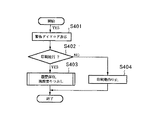
以下、本実施形態における偽造防止処理について、図4に示すフローチャートを参照して説明する。
【0042】
まずステップS401において、PDLドライバ2023はOSに対して複製禁止データが含まれていることを通知し、これを受けたOS側では、ユーザに対して図5に示すような警告ダイアログを表示することによって、この処理は偽造、即ち犯罪となる可能性がある旨を報知する。
【0043】
次にステップS402において、上記警告ダイアログに対し、ユーザが「いいえ」(=印刷中止)を選択した場合は、ステップS404でPDLドライバ2023は当該データの印刷動作を中止し、処理を終了する。
【0044】
一方、上記警告ダイアログに対し、ユーザが「はい」(=印刷続行)を選択した場合は、ホストコンピュータ200内の不図示のハードディスク装置等に操作履歴を保存すると共に、当該画像部を黒く塗りつぶす等の偽造防止処理を行って(S403)、偽造防止処理ルーチン(S305)を終了する。尚、上記画像部の塗りつぶしは偽造防止処理の一例に過ぎず、イメージデータに対してその画質を劣化させるような画像処理、即ち入力画像の忠実な再現を妨げるような処理であれば、どのような処理を施しても良い。
【0045】
上記の一連の処理により印刷動作が中止されなかった場合は、PDLドライバ2023から出力された印刷情報は、図1に示すプリンタ100へホストI/F111を介して入力される。
【0046】
プリンタ100は、ホストコンピュータ200から入力された印刷情報を解析して印刷イメージ(ビットマップイメージデータ)の生成処理を行うと共にプリンタ100全体の制御を行うフォーマッタ制御部110と、前記印刷イメージを受け、記録紙上に可視像として形成するためのプリンタエンジン140に大別される。
【0047】
フォーマッタ制御部110は、ユーザによる操作およびプリンタの状態報知のためのスイッチおよびLED表示器等が配されているオペレーションパネル部120と接続されている。オペレーションパネル部120は、プリンタ100の外装の一部として配設されている。
【0048】
次に、プリンタ100におけるフォーマッタ制御部110について、図6を参照して説明する。
【0049】
フォーマッタ制御部110は、一般にPDLコントローラ等と称される部分であり、ホストコンピュータ200との接続手段であるホストインタフェース(I/F)111と、受信データ等を一時的に保持管理するための記憶手段である受信バッファ1121、送信データ等を一時的に保持管理するための記憶手段である送信バッファ1122、印刷データの解析を司るコマンド解析部113、印刷制御部114、描画処理部115、ページメモリ116、等により構成されている。
【0050】
ホストインタフェース111は、ホストコンピュータ200との印刷データの送受信を行う通信手段あり、通信プロトコルとして IEEE-1284 に準拠した通信を可能とする。但し、本発明はこの通信プロトコルに限定するものでなく、ネットワークを介してさまざまなプロトコルによる接続を可能としてもよいし、IEEE-1394、又はUSB等に準じた通信手段であってもよい。
【0051】
ホストインタフェース111を介して受信した印刷データは受信バッファ1121に逐次蓄積され、必要に応じてコマンド解析部113または描画処理部115によって読み出されて処理される。
【0052】
コマンド解析部113は、各PDLコマンド体系や印刷ジョブ制御言語に準じた制御プログラムにより構成されており、文字印刷、図形、イメージなどの描画に関する印刷データの解析結果に基づいて描画処理部115に指示を与え、給紙選択やリセット命令などの描画以外のコマンドについては印刷制御部114に指示を出して処理を行う。
【0053】
描画処理部115は、文字やイメージの各描画オブジェクトをページメモリ116に逐次展開していく、レンダラとしての機能を有するものである。出力制御部130は、ページメモリ116の内容をビデオ信号に変換し、該ビデオ信号VDOをビデオI/F150を介してプリンタエンジン140へ転送する。
【0054】
プリンタエンジン140は、受け取ったビデオ信号を記録紙に永久可視画像として形成するための印刷機構部である。以下、プリンタエンジン140の構成を図7に示し、その動作について説明する。
【0055】
図7において、給紙カセット161から給紙された用紙Pは、その先端をグリッパ154fにより狭持されて、転写ドラム154の外周に保持される。光学ユニット170により感光ドラム151上に形成された各色の潜像は、イエロー(Y)、マゼンタ(M)、シアン(C)、ブラック(B)の各色現像器Dy、Dm、Dc、Dbにより現像化されて、転写ドラム外周の用紙に複数回転写されて多色画像が形成される。その後、用紙Pは転写ドラム154より分離されて、定着ユニット155で定着され、排紙部159より排紙トレー部160に排出される。
【0056】
ここで各色の現像器Dy、Dm、Dc、Dbは、その両端に回転支軸を有し、各々がその軸を中心に回転可能となるように現像器選択機構部152に保持される。これによって、各現像器Dy、Dc、Db、Dnは図7に示すように、現像器選択のために現像器選択機構部152が回転軸152aを中心にして回転しても、その姿勢を一定に維持できる構成となっている。
【0057】
選択された現像器が現像位置に移動後、現像器選択機構部152は現像器と一体で支点153bを中心にして、選択機構保持フレーム153がソレノイド153aにより感光ドラム151方向へ引っ張られ、感光ドラム151方向へ移動して現像処理が行われるように構成されている。
【0058】
次に、帯電器156によって感光ドラム151が所定の極性に均一に帯電される。フォーマッタ制御部110において印刷イメージとして展開された画像データVDOは、対応するパターンのビデオ信号に変換されてレーザドライバに出力され、半導体レーザ141を駆動する。
【0059】
入力されたビデオ信号VDOに応じて、半導体レーザ141から発射されるレーザ光はオンオフ制御され、さらにスキャナモータ143によって高速回転するポリゴンミラー142で左右方向に振らされ、ポリゴンレンズ134、反射鏡144を介して感光ドラム151上を走査露光する。これにより、感光ドラム151上には画像パターンの静電潜像が形成されることになる。
【0060】
次に、例えば、M(マゼンタ)色の静電潜像がM(マゼンタ)色の現像器Dmにより現像され、感光体ドラム151上にM(マゼンタ)色の第1のトナー像が形成される。
【0061】
一方、所定のタイミングで転写紙Pが給紙され、トナーと反対極性(例えばプラス極性)の転写バイアス電圧が転写ドラム154に印加され、感光体ドラム151上の第1トナー像が転写紙Pに転写されると共に、転写紙Pが転写ドラム154の表面に静電吸着される。その後、感光ドラム151はクリーナ157によって残留するM(マゼンタ)色トナーが除去され、次の色の潜像形成及び現像行程に備える。
【0062】
以下同様の手順によって、C(シアン)、Y(イエロー)、Bk(ブラック)の順で第2、第3、第4色目のトナー像の転写が行われる。但し、各色の転写時には、転写ドラム154には前回よりも高いバイアス電圧が印加される点が異なる。
【0063】
4色のトナー像が重畳転写された転写紙Pの先端部が分離位置に近づくと、分離爪158が接近してその先端が転写ドラム154の表面に接触し、転写紙Pを転写ドラム154から分離させる。分離された転写紙Pは定着ユニット155に搬送され、ここで転写紙上のトナー像が定着されて排紙トレイ160上に排出される。本実施形態のプリンタエンジン140は、以上のような画像形成過程を経て、600ドット/インチ(dpi)まで解像度による画像出力を可能とする。
以上説明したように本実施形態によれば、プリンタドライバ2020において、所定解像度を越えるイメージデータのみに対して電子透かしの検出処理を行う。これにより、電子透かしの検出処理の実行を必要最小限に抑制することができるため、全体としてのスループットの低下を抑制しつつ、紙幣や有価証券の偽造防止機能を実現することができる。
【0064】
尚、本実施形態ではカラーレーザビームプリンタに対して本発明を適用した例を説明したが、本発明を適用可能なプリンタは、カラーレーザビームプリンタに限られるものではなく、インクジェットプリンタやサーマルプリンタ等、他のプリント方式のカラープリンタであっても良いことはもちろんである。
【0065】
また、本実施形態においては電子透かし検出処理を行うか否か、即ち偽造判定処理を行うか否かの判断基準となる解像度を100dpiとして説明した。一般に、例えばインターネット上の画像をプリントアウトする場合等に頻繁に送られるデータの解像度は100dpi以下であるため、本実施形態のように100dpi以下のイメージデータに対して偽造判定処理をスキップすることは、処理時間の短縮に効果的である。もちろん、偽造判定処理の判断基準として他の解像度を適用しても、本発明の趣旨を変えるものではない。
【0066】
<変形例>
上述した実施形態においては、出力解像度が所定値を越えるか否かに応じて、偽造判定処理を実行する例について説明したが、この出力解像度に加えて更に、出力画像サイズを判断基準に加えることが可能である。
【0067】
例えば、出力解像度が高くても出力画像のサイズが小さければ、該イメージデータに基づく印刷物は偽造物として通用しないため、出力画像サイズが所定値以下(例えば、縦5cm×横5cm以内)であれば、偽造判定処理をスキップするように制御する。
【0068】
このように、所定解像度以下の判断基準に加えて、更に所定サイズ以下のデータについても偽造判定処理を行わないことにより、処理時間のさらなる短縮が可能となる。
【0069】
もちろん、偽造判定処理の実行判断基準としてはこの例に限るものではなく、設定された出力パラメータが、そのまま印刷を行えばその出力画像は偽造物として通用しないような設定あれば、偽造判定処理を行うか否かの判断基準として採用することが可能である。
【0070】
【他の実施形態】
なお、本発明は、複数の機器(例えばホストコンピュータ、インタフェイス機器、リーダ、プリンタなど)から構成されるシステムに適用しても、一つの機器からなる装置(例えば、複写機、ファクシミリ装置など)に適用してもよい。
【0071】
また、本発明の目的は、前述した実施形態の機能を実現するソフトウェアのプログラムコードを記録した記憶媒体(または記録媒体)を、システムあるいは装置に供給し、そのシステムあるいは装置のコンピュータ(またはCPUやMPU)が記憶媒体に格納されたプログラムコードを読み出し実行することによっても、達成されることは言うまでもない。この場合、記憶媒体から読み出されたプログラムコード自体が前述した実施形態の機能を実現することになり、そのプログラムコードを記憶した記憶媒体は本発明を構成することになる。また、コンピュータが読み出したプログラムコードを実行することにより、前述した実施形態の機能が実現されるだけでなく、そのプログラムコードの指示に基づき、コンピュータ上で稼働しているオペレーティングシステム(OS)などが実際の処理の一部または全部を行い、その処理によって前述した実施形態の機能が実現される場合も含まれることは言うまでもない。
【0072】
さらに、記憶媒体から読み出されたプログラムコードが、コンピュータに挿入された機能拡張カードやコンピュータに接続された機能拡張ユニットに備わるメモリに書込まれた後、そのプログラムコードの指示に基づき、その機能拡張カードや機能拡張ユニットに備わるCPUなどが実際の処理の一部または全部を行い、その処理によって前述した実施形態の機能が実現される場合も含まれることは言うまでもない。
【0073】
【発明の効果】
以上説明したように本発明によれば、プリンタドライバにおける偽造判定処理の負荷が軽減されることにより、高速プリントが可能となる。
【図面の簡単な説明】
【図1】本発明に係る一実施形態における印刷システムの全体構成を示す図である。
【図2】グラフィックサブシステムの構成を示すブロック図である。
【図3】偽造判定処理を示すフローチャートである。
【図4】偽造防止処理を示すフローチャートである。
【図5】ユーザに対する警告ダイアログの一例を示す図である。
【図6】フォーマッタ制御部の構成を示すブロック図である。
【図7】プリンタエンジンの横断面図である。
【符号の説明】
100 プリンタ
110 フォーマッタ制御部
120 オペレーションパネル
130 出力制御部
140 プリンタエンジン
200 ホストコンピュータ
201 アプリケーション
202 グラフィックサブシステム
2020 プリンタドライバ
2021,2028 GDI
2022 セレクタ
2023 PDLドライバ
2024 イメージドライバ
2025,2026 偽造判定部
2027 バンドメモリ[0001]
BACKGROUND OF THE INVENTION
The present invention relates to an image forming system and a control method therefor, and more particularly to an image forming system and a control method therefor that form a faithful image based on image data on a recording medium.
[0002]
[Prior art]
In recent years, with the improvement of the performance of color image reading devices (scanners) and color printers, for specific originals that are subject to duplication, such as banknotes and securities, by reading the originals with a color scanner and outputting them to a color printer, There is a growing risk of being counterfeited.
[0003]
In order to prevent such forgery, for example, in a color copying machine that is a combination of a color scanner and a color printer, an anti-counterfeiting device that recognizes whether or not a document to be processed is a specific document and performs a copy inhibition process Are increasingly being incorporated.
[0004]
However, since the anti-counterfeiting device used in the color copying machine operates only at the time of copying, the copy-prohibited document is read once by a scanner or the like, and the obtained image data is output by a color printer. There was a possibility of counterfeiting. In general, the conventional anti-counterfeiting apparatus is expensive, so that it is difficult to mount it on a small and inexpensive color copying machine or printer.
[0005]
On the other hand, so-called digital watermarking technology for embedding copyright information in digital contents such as images and music is being put into practical use. Therefore, it has been proposed to apply this digital watermark technology to the forgery prevention device as described above. For example, forgery can be prevented by embedding information by electronic watermark in advance in a printed matter (specific original) that is prohibited from copying, and detecting the electronic watermark information at the time of copying or printing the printed matter.
[0006]
[Problems to be solved by the invention]
However, when the forgery determination process using the digital watermark as described above is executed in the printer driver, an excessive load is applied to the CPU of the host computer. Therefore, there is a drawback that the printing speed in the apparatus is remarkably reduced by executing the forgery determination process.
[0007]
The present invention has been made to solve the above-described problems, and provides an image forming system and a control method thereof capable of realizing high-speed printing by reducing the load of forgery determination processing in a printer driver. Objective.
[0008]
[Means for Solving the Problems]
As a technique for achieving the above object, a method for controlling an image forming system according to the present invention includes the following steps. That is, generate image data Computer And a control method of an image forming system in which a visible image based on the image data is formed on a recording medium. Printer driver in computer Input process for inputting print information and image data indicated by the input print information Resolution Is the predetermined resolution Over Resolution determination step for determining whether or not, An image size determination step for determining whether the size of an output image based on the input print information exceeds a predetermined size, and detection for detecting whether digital watermark information indicating that copying is prohibited is embedded in the image data Process, and detection In the process, the image data Detects that the watermark information is embedded in If Prevent faithful reproduction of the input print information Execute the process Reproduction prevention Processing process When the resolution determination step determines that the resolution of the image data is equal to or less than the predetermined resolution, or the image size determination step determines that the size of the output image is equal to or less than the predetermined size, the detection step Skip It is characterized by that.
[0009]
DETAILED DESCRIPTION OF THE INVENTION
Hereinafter, an embodiment according to the present invention will be described in detail with reference to the drawings.
[0010]
<First Embodiment>
FIG. 1 is a diagram showing an overall configuration of a printing system using a color laser beam printer to which the present embodiment is applied.
[0011]
In the figure,
[0012]
On the
[0013]
The
[0014]
As shown in FIG. 2, the
[0015]
The
[0016]
Here, the PDL mode type corresponds to a printer equipped with a controller capable of processing a control command called PDL (Printer Description Language), and the
[0017]
Since the process of the
[0018]
As a feature of the PDL mode type, if the
[0019]
However, in the PDL mode type, when drawing a graphic with gradation or the like in a graphics application or outputting a high resolution / high gradation image, a large print command is generated, so the processing speed is extremely high. Often slow.
[0020]
On the other hand, with the image mode type, a print image is developed in a memory space secured on the
[0021]
As the processing of the
[0022]
A feature of the image mode type is that high-resolution color images and complex graphics data can be drawn at high speed. On the other hand, even when drawing characters or simple figures, image data of the entire drawing area is generated with the output resolution and output gradation and sent as a print command. For high-speed printing, the processing time is rather increased.
[0023]
Hereinafter, forgery determination processing in the
[0024]
The
[0025]
The print information has three types of attributes: “text” that is font information, “graphics” that consists of graphic vectors and gradation information, and “image” that is a read image of a photo. Different functions are used. Further, since the data of the “image” attribute includes information such as the number of pixels in the vertical and horizontal directions and the output image size, only the data of the “image” attribute satisfying the above resolution condition when the print information is received from the DDI. It is easy to extract and process.
[0026]
Hereinafter, the forgery determination process in the
[0027]
In FIG. 3, the print information is first input in step S301. The print information includes not only image data created by the
[0028]
Generally, when copying banknotes, securities, etc., image data to be processed has a resolution of a certain level or more in order to faithfully reproduce a document image read by the
[0029]
In step S302, if the input print information is image data having an output resolution of 100 dpi or less, the process proceeds to step S306, and the
[0030]
On the other hand, if the input print information is image data exceeding the output resolution of 100 dpi, the process advances to step S303 to perform digital watermark detection processing.
[0031]
Hereinafter, the digital watermark detection process in step S303 will be described. In the present embodiment, if specific digital watermark information indicating copy prohibition is detected for input image data exceeding 100 dpi, the image data is based on a specific document and may be forged. to decide. Hereinafter, a method for extracting digital watermark information in the present embodiment will be described. However, the present invention is not particularly limited to this method, and a known extraction method can be applied.
[0032]
First, input image data is divided into blocks, and Fourier transform is performed for each block to extract frequency components. The obtained frequency domain image data is separated into an amplitude spectrum and a phase spectrum, and a registration signal included in the amplitude spectrum is detected.
[0033]
In general, according to human visual characteristics, embedding a signal in a low-frequency component is more easily recognized as noise than embedding a signal in a high-frequency component. In addition, irreversible compression such as JPEG has a low-pass filter effect, and is characterized by removing high-frequency components by performing compression / decompression processing using JPEG.
[0034]
The registration signal is not more than a first frequency level that is difficult for humans to see, based on the characteristics of these high-frequency components and low-frequency components, and is not less than a second frequency level that is not removed by lossy compression and expansion. Embedded as an impulse signal to an intermediate level frequency. Therefore, a registration signal is detected by extracting an impulse signal in the frequency domain at the intermediate level included in the amplitude spectrum.
[0035]
Then, the scaling rate of the digital image data is calculated based on the coordinates of the extracted registration signal (impulse signal).
[0036]
The digital
[0037]
For example, if the frequency recognized in advance is a and the frequency of the detected impulse signal is b, it can be seen that a / b scaling is performed. This is a property in the well-known Fourier transform.
[0038]
By determining the size of the pattern for detecting the digital watermark information included in the image data based on the scaling rate and performing the convolution using the pattern, the digital watermark information can be detected.
[0039]
As a result of the digital watermark detection process (S303) described above, if digital watermark information indicating copy prohibition is not detected (S304), the
[0040]
On the other hand, when the electronic watermark information subject to copy prohibition is detected, the
[0041]
Hereinafter, the forgery prevention process according to the present embodiment will be described with reference to a flowchart shown in FIG.
[0042]
First, in step S401, the
[0043]
In step S402, if the user selects “No” (= printing cancel) in response to the warning dialog, in step S404, the
[0044]
On the other hand, if the user selects “Yes” (= continue printing) in response to the warning dialog, the operation history is stored in a hard disk device (not shown) in the
[0045]
When the printing operation is not stopped by the above-described series of processing, the print information output from the
[0046]
The
[0047]
The
[0048]
Next, the
[0049]
The
[0050]
The
[0051]
The print data received via the
[0052]
The
[0053]
The
[0054]
The
[0055]
In FIG. 7, the paper P fed from the
[0056]
Here, the developing devices Dy, Dm, Dc, and Db of the respective colors have rotation support shafts at both ends, and are held by the developing device
[0057]
After the selected developing device moves to the developing position, the developing
[0058]
Next, the charging
[0059]
In accordance with the input video signal VDO, the laser light emitted from the
[0060]
Next, for example, an M (magenta) electrostatic latent image is developed by an M (magenta) developer Dm, and an M (magenta) first toner image is formed on the
[0061]
On the other hand, the transfer paper P is fed at a predetermined timing, a transfer bias voltage having a polarity opposite to that of the toner (for example, plus polarity) is applied to the
[0062]
Thereafter, the toner images of the second, third, and fourth colors are transferred in the order of C (cyan), Y (yellow), and Bk (black) by the same procedure. However, a difference is that a bias voltage higher than that of the previous time is applied to the
[0063]
When the leading edge of the transfer paper P onto which the four-color toner images are superimposed and transferred approaches the separation position, the
As described above, according to the present embodiment, the
[0064]
In the present embodiment, an example in which the present invention is applied to a color laser beam printer has been described. However, printers to which the present invention can be applied are not limited to color laser beam printers, such as inkjet printers and thermal printers. Of course, other color printers may be used.
[0065]
Further, in the present embodiment, the description has been given assuming that the resolution, which is a determination criterion of whether to perform the digital watermark detection process, that is, whether to perform the forgery determination process, is 100 dpi. Generally, the resolution of data that is frequently sent, for example, when printing out an image on the Internet is 100 dpi or less, so that forgery determination processing is not performed on image data of 100 dpi or less as in this embodiment. It is effective for shortening the processing time. Of course, applying other resolutions as judgment criteria for the forgery judgment process does not change the gist of the present invention.
[0066]
<Modification>
In the above-described embodiment, the example in which the forgery determination process is executed according to whether the output resolution exceeds a predetermined value has been described. However, in addition to the output resolution, the output image size is further added to the determination criterion. Is possible.
[0067]
For example, even if the output resolution is high, if the size of the output image is small, the printed matter based on the image data cannot be used as a counterfeit, so if the output image size is a predetermined value or less (for example, within 5 cm x 5 cm). , Control to skip the forgery determination process.
[0068]
In this way, in addition to the determination criterion of a predetermined resolution or less, the processing time can be further shortened by not performing the forgery determination process for data of a predetermined size or less.
[0069]
Of course, the execution determination criterion of the forgery determination process is not limited to this example, and if the set output parameter is set so that the output image is not accepted as a forgery if printing is performed as it is, the forgery determination process is performed. It can be adopted as a criterion for determining whether or not to perform.
[0070]
[Other Embodiments]
Note that the present invention can be applied to a system including a plurality of devices (for example, a host computer, an interface device, a reader, and a printer), and a device (for example, a copying machine and a facsimile device) including a single device. You may apply to.
[0071]
Another object of the present invention is to supply a storage medium (or recording medium) in which a program code of software that realizes the functions of the above-described embodiments is recorded to a system or apparatus, and the computer (or CPU or CPU) of the system or apparatus. Needless to say, this can also be achieved by the MPU) reading and executing the program code stored in the storage medium. In this case, the program code itself read from the storage medium realizes the functions of the above-described embodiment, and the storage medium storing the program code constitutes the present invention. Further, by executing the program code read by the computer, not only the functions of the above-described embodiments are realized, but also an operating system (OS) running on the computer based on the instruction of the program code. It goes without saying that a case where the function of the above-described embodiment is realized by performing part or all of the actual processing and the processing is included.
[0072]
Furthermore, after the program code read from the storage medium is written into a memory provided in a function expansion card inserted into the computer or a function expansion unit connected to the computer, the function is determined based on the instruction of the program code. It goes without saying that the CPU or the like provided in the expansion card or the function expansion unit performs part or all of the actual processing and the functions of the above-described embodiments are realized by the processing.
[0073]
【The invention's effect】
As described above, according to the present invention, it is possible to perform high-speed printing by reducing the load of forgery determination processing in the printer driver.
[Brief description of the drawings]
FIG. 1 is a diagram illustrating an overall configuration of a printing system according to an embodiment of the present invention.
FIG. 2 is a block diagram showing a configuration of a graphic subsystem.
FIG. 3 is a flowchart showing forgery determination processing;
FIG. 4 is a flowchart showing forgery prevention processing;
FIG. 5 is a diagram illustrating an example of a warning dialog for a user.
FIG. 6 is a block diagram illustrating a configuration of a formatter control unit.
FIG. 7 is a cross-sectional view of the printer engine.
[Explanation of symbols]
100 printer
110 Formatter Control Unit
120 Operation panel
130 Output controller
140 Printer Engine
200 Host computer
201 Application
202 Graphics subsystem
2020 Printer driver
2021, 2028 GDI
2022 selector
2023 PDL driver
2024 image driver
2025, 2026 Counterfeit determination unit
2027 band memory
Claims (8)
前記コンピュータにおけるプリンタドライバにおいて、
印刷情報を入力する入力工程と、
該入力された印刷情報によって示される画像データの解像度が所定解像度を超えるか否かを判定する解像度判定工程と、
前記入力された印刷情報による出力画像のサイズが所定サイズを超えるか否かを判定する画像サイズ判定工程と、
前記画像データに複製禁止を示す電子透かし情報が埋め込まれているか否かを検出する検出工程と、
前記検出工程において、前記画像データに前記電子透かし情報が埋め込まれていると検出された場合に、前記入力された印刷情報の忠実な再現を防ぐ処理を実行する再現防止処理工程と、
を有し、
前記解像度判定工程において前記画像データの解像度が前記所定解像度以下である、又は、前記画像サイズ判定工程において前記出力画像のサイズが前記所定サイズ以下であると判定された場合は、前記検出工程をスキップする
ことを特徴とする画像形成システムの制御方法。A control method of an image forming system in which a computer that generates image data and an image forming apparatus that forms a visible image based on the image data on a recording medium are connected,
In the printer driver in the computer ,
An input process for inputting print information;
A resolution determination step for determining whether the resolution of the image data indicated by the input print information exceeds a predetermined resolution;
An image size determination step for determining whether the size of the output image by the input print information exceeds a predetermined size;
A detection step of detecting whether digital watermark information indicating prohibition of copying is embedded in the image data ;
In the detection step, when it is detected that the digital watermark information is embedded in the image data , a reproduction prevention processing step for executing processing for preventing faithful reproduction of the input print information ;
I have a,
When the resolution determination step determines that the resolution of the image data is less than or equal to the predetermined resolution, or the image size determination step determines that the size of the output image is less than or equal to the predetermined size, the detection step is skipped. A method for controlling an image forming system.
前記コンピュータにおけるプリンタドライバは、
入力された印刷情報によって示される画像データの解像度が所定解像度を超えるか否かを判定し、
前記入力された印刷情報による出力画像のサイズが所定サイズを超えるか否かを判定し、
該画像データに複製禁止を示す電子透かし情報が埋め込まれているか否かを検出し、
該画像データに前記電子透かし情報が埋め込まれていると検出された場合に、前記入力された印刷情報の忠実な再現を防ぐ処理を実行し、
前記画像データの解像度が前記所定解像度以下である、又は、前記出力画像のサイズが前記所定サイズ以下であると判定された場合は、前記検出を行わない
ことを特徴とする画像形成システム。An image forming system in which a computer that generates image data and an image forming apparatus that forms a visible image based on the image data on a recording medium are connected,
The printer driver in the computer is
Determining whether the resolution of the image data indicated by the input print information exceeds a predetermined resolution;
Determining whether the size of the output image by the input print information exceeds a predetermined size;
Detecting whether or not digital watermark information indicating prohibition of copying is embedded in the image data ;
When it is detected that the digital watermark information is embedded in the image data , a process for preventing faithful reproduction of the input print information is executed .
The image forming is characterized in that the detection is not performed when it is determined that the resolution of the image data is equal to or lower than the predetermined resolution, or the size of the output image is equal to or smaller than the predetermined size. system.
前記画像データに複製禁止を示す電子透かし情報が埋め込まれているか否かを検出する検出手段と、
該画像データに前記電子透かし情報が埋め込まれていると検出された場合に、前記入力された印刷情報の忠実な再現を防ぐ処理を実行する画像処理手段と、
を有し、
前記検出手段は、
前記画像データの解像度が前記所定解像度以下である、又は、前記出力画像のサイズが 前記所定サイズ以下であると判定された場合は、前記検出を行わない
ことを特徴とする画像処理装置。Input means for inputting image data;
Detecting means for detecting whether or not digital watermark information indicating prohibition of copying is embedded in the image data ;
Image processing means for executing processing for preventing faithful reproduction of the input print information when it is detected that the digital watermark information is embedded in the image data;
I have a,
The detection means includes
The image processing is characterized in that the detection is not performed when it is determined that the resolution of the image data is equal to or less than the predetermined resolution, or the size of the output image is equal to or less than the predetermined size. apparatus.
該画像データに基づく可視像を記録媒体上に形成する画像形成装置を制御するためのプログラムを記録した記録媒体であって、該プログラムは少なくとも、
印刷情報を入力する入力工程のコードと、
該入力された印刷情報によって示される画像データの解像度が所定解像度を超えるか否かを判定する解像度判定工程のコードと、
前記入力された印刷情報による出力画像のサイズが所定サイズを超えるか否かを判定する画像サイズ判定工程のコードと、
前記画像データに複製禁止を示す電子透かし情報が埋め込まれているか否かを検出する検出工程のコードと、
前記検出工程において、前記画像データに前記電子透かし情報が埋め込まれていると検出された場合に、前記入力された印刷情報の忠実な再現を防ぐ処理を実行する再現防止処理工程のコードと、
を有し、
前記解像度判定工程において前記画像データの解像度が前記所定解像度以下である、又は、前記画像サイズ判定工程において前記出力画像のサイズが前記所定サイズ以下であると判定された場合は、前記検出工程をスキップするコードを更に有する
ことを特徴とする記録媒体。In an image processing apparatus that generates image data,
A recording medium recording a program for controlling an image forming apparatus that forms a visible image on a recording medium based on the image data, the program being at least
An input process code for entering print information;
A code for a resolution determination step for determining whether the resolution of the image data indicated by the input print information exceeds a predetermined resolution;
A code of an image size determination step for determining whether the size of the output image according to the input print information exceeds a predetermined size;
A code of a detection step for detecting whether or not digital watermark information indicating prohibition of copying is embedded in the image data ;
In the detection step, when it is detected that the digital watermark information is embedded in the image data , a code of a reproduction prevention processing step for executing processing for preventing faithful reproduction of the input print information ;
I have a,
When the resolution determination step determines that the resolution of the image data is less than or equal to the predetermined resolution, or the image size determination step determines that the size of the output image is less than or equal to the predetermined size, the detection step is skipped. A recording medium further comprising:
Priority Applications (2)
| Application Number | Priority Date | Filing Date | Title |
|---|---|---|---|
| JP2000022100A JP3880269B2 (en) | 2000-01-31 | 2000-01-31 | Image forming system and control method thereof |
| US09/768,330 US7193744B2 (en) | 2000-01-31 | 2001-01-25 | Image forming system and its control method |
Applications Claiming Priority (1)
| Application Number | Priority Date | Filing Date | Title |
|---|---|---|---|
| JP2000022100A JP3880269B2 (en) | 2000-01-31 | 2000-01-31 | Image forming system and control method thereof |
Publications (3)
| Publication Number | Publication Date |
|---|---|
| JP2001218038A JP2001218038A (en) | 2001-08-10 |
| JP2001218038A5 JP2001218038A5 (en) | 2004-10-07 |
| JP3880269B2 true JP3880269B2 (en) | 2007-02-14 |
Family
ID=18548434
Family Applications (1)
| Application Number | Title | Priority Date | Filing Date |
|---|---|---|---|
| JP2000022100A Expired - Fee Related JP3880269B2 (en) | 2000-01-31 | 2000-01-31 | Image forming system and control method thereof |
Country Status (1)
| Country | Link |
|---|---|
| JP (1) | JP3880269B2 (en) |
Families Citing this family (4)
| Publication number | Priority date | Publication date | Assignee | Title |
|---|---|---|---|---|
| JP4554347B2 (en) * | 2004-12-20 | 2010-09-29 | 株式会社リコー | Image forming apparatus and control method thereof |
| US20060209348A1 (en) * | 2005-03-16 | 2006-09-21 | Kabushiki Kaisha Toshiba | Image processing apparatus |
| JP5005840B1 (en) * | 2012-03-28 | 2012-08-22 | 三菱電機インフォメーションシステムズ株式会社 | Content data management system and program |
| JP6679999B2 (en) * | 2016-03-10 | 2020-04-15 | コニカミノルタ株式会社 | Image processing device and program |
-
2000
- 2000-01-31 JP JP2000022100A patent/JP3880269B2/en not_active Expired - Fee Related
Also Published As
| Publication number | Publication date |
|---|---|
| JP2001218038A (en) | 2001-08-10 |
Similar Documents
| Publication | Publication Date | Title |
|---|---|---|
| JP5078480B2 (en) | Image processing apparatus and method, and computer program and recording medium | |
| JP4235347B2 (en) | Information processing apparatus, information processing method, and storage medium | |
| JP3826038B2 (en) | Printing system, printing method therefor, and printing apparatus | |
| US20070086050A1 (en) | Information processing apparatus, image processing method, and machine-readable medium | |
| US7193744B2 (en) | Image forming system and its control method | |
| US8031366B2 (en) | Control apparatus, controlling method, program and recording medium | |
| US20100020338A1 (en) | Printing apparatus, control method, and storage medium | |
| JP3962606B2 (en) | Printing command generation apparatus and method, printing apparatus and control method thereof, information processing apparatus, and printing system | |
| US7746494B2 (en) | Data processing apparatus, data processing method, printer driver, print control apparatus, print control method, and printing system | |
| JP4894488B2 (en) | Image processing apparatus and image processing method | |
| JP3880269B2 (en) | Image forming system and control method thereof | |
| JP3832521B2 (en) | Image forming apparatus and image processing apparatus | |
| JP4018426B2 (en) | Image processing system and control method thereof | |
| JP4095166B2 (en) | Image processing apparatus and method | |
| JP2001313819A (en) | Image processor, storage medium | |
| JP2000125135A (en) | Image forming device and image processor | |
| JP2005348450A (en) | Image processing method, and storage medium | |
| JP2001218013A (en) | Image formation system and its controlling method | |
| JPH1132214A (en) | Image-forming device and image-processing device | |
| JP4857083B2 (en) | Image forming system and image forming apparatus | |
| JP2000307857A (en) | Pattern detecting method, image processing control method, image processor and recording medium | |
| JPH10285385A (en) | Picture-processing system/device/method and storage medium | |
| JP2006235813A (en) | Print system | |
| JP4500393B2 (en) | Image forming system, information processing apparatus, and image processing apparatus control method | |
| JP3835513B2 (en) | Printer driver, image processing method, drawing processing apparatus, and image forming system |
Legal Events
| Date | Code | Title | Description |
|---|---|---|---|
| A977 | Report on retrieval |
Free format text: JAPANESE INTERMEDIATE CODE: A971007 Effective date: 20060414 |
|
| A131 | Notification of reasons for refusal |
Free format text: JAPANESE INTERMEDIATE CODE: A131 Effective date: 20060418 |
|
| A521 | Written amendment |
Free format text: JAPANESE INTERMEDIATE CODE: A523 Effective date: 20060619 |
|
| TRDD | Decision of grant or rejection written | ||
| A01 | Written decision to grant a patent or to grant a registration (utility model) |
Free format text: JAPANESE INTERMEDIATE CODE: A01 Effective date: 20061016 |
|
| A61 | First payment of annual fees (during grant procedure) |
Free format text: JAPANESE INTERMEDIATE CODE: A61 Effective date: 20061107 |
|
| R150 | Certificate of patent or registration of utility model |
Free format text: JAPANESE INTERMEDIATE CODE: R150 |
|
| FPAY | Renewal fee payment (event date is renewal date of database) |
Free format text: PAYMENT UNTIL: 20101117 Year of fee payment: 4 |
|
| FPAY | Renewal fee payment (event date is renewal date of database) |
Free format text: PAYMENT UNTIL: 20101117 Year of fee payment: 4 |
|
| FPAY | Renewal fee payment (event date is renewal date of database) |
Free format text: PAYMENT UNTIL: 20111117 Year of fee payment: 5 |
|
| FPAY | Renewal fee payment (event date is renewal date of database) |
Free format text: PAYMENT UNTIL: 20121117 Year of fee payment: 6 |
|
| FPAY | Renewal fee payment (event date is renewal date of database) |
Free format text: PAYMENT UNTIL: 20131117 Year of fee payment: 7 |
|
| LAPS | Cancellation because of no payment of annual fees |