JP3851063B2 - Image predictive decoding method and apparatus - Google Patents
Image predictive decoding method and apparatus Download PDFInfo
- Publication number
- JP3851063B2 JP3851063B2 JP2000186294A JP2000186294A JP3851063B2 JP 3851063 B2 JP3851063 B2 JP 3851063B2 JP 2000186294 A JP2000186294 A JP 2000186294A JP 2000186294 A JP2000186294 A JP 2000186294A JP 3851063 B2 JP3851063 B2 JP 3851063B2
- Authority
- JP
- Japan
- Prior art keywords
- block
- prediction
- coefficient
- image data
- image
- Prior art date
- Legal status (The legal status is an assumption and is not a legal conclusion. Google has not performed a legal analysis and makes no representation as to the accuracy of the status listed.)
- Expired - Lifetime
Links
Images


Classifications
-
- H—ELECTRICITY
- H04—ELECTRIC COMMUNICATION TECHNIQUE
- H04N—PICTORIAL COMMUNICATION, e.g. TELEVISION
- H04N19/00—Methods or arrangements for coding, decoding, compressing or decompressing digital video signals
- H04N19/10—Methods or arrangements for coding, decoding, compressing or decompressing digital video signals using adaptive coding
- H04N19/102—Methods or arrangements for coding, decoding, compressing or decompressing digital video signals using adaptive coding characterised by the element, parameter or selection affected or controlled by the adaptive coding
- H04N19/103—Selection of coding mode or of prediction mode
- H04N19/105—Selection of the reference unit for prediction within a chosen coding or prediction mode, e.g. adaptive choice of position and number of pixels used for prediction
-
- H—ELECTRICITY
- H04—ELECTRIC COMMUNICATION TECHNIQUE
- H04N—PICTORIAL COMMUNICATION, e.g. TELEVISION
- H04N19/00—Methods or arrangements for coding, decoding, compressing or decompressing digital video signals
- H04N19/10—Methods or arrangements for coding, decoding, compressing or decompressing digital video signals using adaptive coding
- H04N19/102—Methods or arrangements for coding, decoding, compressing or decompressing digital video signals using adaptive coding characterised by the element, parameter or selection affected or controlled by the adaptive coding
- H04N19/103—Selection of coding mode or of prediction mode
- H04N19/11—Selection of coding mode or of prediction mode among a plurality of spatial predictive coding modes
-
- H—ELECTRICITY
- H04—ELECTRIC COMMUNICATION TECHNIQUE
- H04N—PICTORIAL COMMUNICATION, e.g. TELEVISION
- H04N19/00—Methods or arrangements for coding, decoding, compressing or decompressing digital video signals
- H04N19/10—Methods or arrangements for coding, decoding, compressing or decompressing digital video signals using adaptive coding
- H04N19/102—Methods or arrangements for coding, decoding, compressing or decompressing digital video signals using adaptive coding characterised by the element, parameter or selection affected or controlled by the adaptive coding
- H04N19/119—Adaptive subdivision aspects, e.g. subdivision of a picture into rectangular or non-rectangular coding blocks
-
- H—ELECTRICITY
- H04—ELECTRIC COMMUNICATION TECHNIQUE
- H04N—PICTORIAL COMMUNICATION, e.g. TELEVISION
- H04N19/00—Methods or arrangements for coding, decoding, compressing or decompressing digital video signals
- H04N19/10—Methods or arrangements for coding, decoding, compressing or decompressing digital video signals using adaptive coding
- H04N19/102—Methods or arrangements for coding, decoding, compressing or decompressing digital video signals using adaptive coding characterised by the element, parameter or selection affected or controlled by the adaptive coding
- H04N19/129—Scanning of coding units, e.g. zig-zag scan of transform coefficients or flexible macroblock ordering [FMO]
-
- H—ELECTRICITY
- H04—ELECTRIC COMMUNICATION TECHNIQUE
- H04N—PICTORIAL COMMUNICATION, e.g. TELEVISION
- H04N19/00—Methods or arrangements for coding, decoding, compressing or decompressing digital video signals
- H04N19/10—Methods or arrangements for coding, decoding, compressing or decompressing digital video signals using adaptive coding
- H04N19/134—Methods or arrangements for coding, decoding, compressing or decompressing digital video signals using adaptive coding characterised by the element, parameter or criterion affecting or controlling the adaptive coding
- H04N19/136—Incoming video signal characteristics or properties
- H04N19/137—Motion inside a coding unit, e.g. average field, frame or block difference
-
- H—ELECTRICITY
- H04—ELECTRIC COMMUNICATION TECHNIQUE
- H04N—PICTORIAL COMMUNICATION, e.g. TELEVISION
- H04N19/00—Methods or arrangements for coding, decoding, compressing or decompressing digital video signals
- H04N19/10—Methods or arrangements for coding, decoding, compressing or decompressing digital video signals using adaptive coding
- H04N19/134—Methods or arrangements for coding, decoding, compressing or decompressing digital video signals using adaptive coding characterised by the element, parameter or criterion affecting or controlling the adaptive coding
- H04N19/146—Data rate or code amount at the encoder output
- H04N19/152—Data rate or code amount at the encoder output by measuring the fullness of the transmission buffer
-
- H—ELECTRICITY
- H04—ELECTRIC COMMUNICATION TECHNIQUE
- H04N—PICTORIAL COMMUNICATION, e.g. TELEVISION
- H04N19/00—Methods or arrangements for coding, decoding, compressing or decompressing digital video signals
- H04N19/10—Methods or arrangements for coding, decoding, compressing or decompressing digital video signals using adaptive coding
- H04N19/134—Methods or arrangements for coding, decoding, compressing or decompressing digital video signals using adaptive coding characterised by the element, parameter or criterion affecting or controlling the adaptive coding
- H04N19/154—Measured or subjectively estimated visual quality after decoding, e.g. measurement of distortion
-
- H—ELECTRICITY
- H04—ELECTRIC COMMUNICATION TECHNIQUE
- H04N—PICTORIAL COMMUNICATION, e.g. TELEVISION
- H04N19/00—Methods or arrangements for coding, decoding, compressing or decompressing digital video signals
- H04N19/10—Methods or arrangements for coding, decoding, compressing or decompressing digital video signals using adaptive coding
- H04N19/169—Methods or arrangements for coding, decoding, compressing or decompressing digital video signals using adaptive coding characterised by the coding unit, i.e. the structural portion or semantic portion of the video signal being the object or the subject of the adaptive coding
- H04N19/17—Methods or arrangements for coding, decoding, compressing or decompressing digital video signals using adaptive coding characterised by the coding unit, i.e. the structural portion or semantic portion of the video signal being the object or the subject of the adaptive coding the unit being an image region, e.g. an object
- H04N19/176—Methods or arrangements for coding, decoding, compressing or decompressing digital video signals using adaptive coding characterised by the coding unit, i.e. the structural portion or semantic portion of the video signal being the object or the subject of the adaptive coding the unit being an image region, e.g. an object the region being a block, e.g. a macroblock
-
- H—ELECTRICITY
- H04—ELECTRIC COMMUNICATION TECHNIQUE
- H04N—PICTORIAL COMMUNICATION, e.g. TELEVISION
- H04N19/00—Methods or arrangements for coding, decoding, compressing or decompressing digital video signals
- H04N19/10—Methods or arrangements for coding, decoding, compressing or decompressing digital video signals using adaptive coding
- H04N19/169—Methods or arrangements for coding, decoding, compressing or decompressing digital video signals using adaptive coding characterised by the coding unit, i.e. the structural portion or semantic portion of the video signal being the object or the subject of the adaptive coding
- H04N19/18—Methods or arrangements for coding, decoding, compressing or decompressing digital video signals using adaptive coding characterised by the coding unit, i.e. the structural portion or semantic portion of the video signal being the object or the subject of the adaptive coding the unit being a set of transform coefficients
-
- H—ELECTRICITY
- H04—ELECTRIC COMMUNICATION TECHNIQUE
- H04N—PICTORIAL COMMUNICATION, e.g. TELEVISION
- H04N19/00—Methods or arrangements for coding, decoding, compressing or decompressing digital video signals
- H04N19/10—Methods or arrangements for coding, decoding, compressing or decompressing digital video signals using adaptive coding
- H04N19/169—Methods or arrangements for coding, decoding, compressing or decompressing digital video signals using adaptive coding characterised by the coding unit, i.e. the structural portion or semantic portion of the video signal being the object or the subject of the adaptive coding
- H04N19/182—Methods or arrangements for coding, decoding, compressing or decompressing digital video signals using adaptive coding characterised by the coding unit, i.e. the structural portion or semantic portion of the video signal being the object or the subject of the adaptive coding the unit being a pixel
-
- H—ELECTRICITY
- H04—ELECTRIC COMMUNICATION TECHNIQUE
- H04N—PICTORIAL COMMUNICATION, e.g. TELEVISION
- H04N19/00—Methods or arrangements for coding, decoding, compressing or decompressing digital video signals
- H04N19/46—Embedding additional information in the video signal during the compression process
-
- H—ELECTRICITY
- H04—ELECTRIC COMMUNICATION TECHNIQUE
- H04N—PICTORIAL COMMUNICATION, e.g. TELEVISION
- H04N19/00—Methods or arrangements for coding, decoding, compressing or decompressing digital video signals
- H04N19/48—Methods or arrangements for coding, decoding, compressing or decompressing digital video signals using compressed domain processing techniques other than decoding, e.g. modification of transform coefficients, variable length coding [VLC] data or run-length data
-
- H—ELECTRICITY
- H04—ELECTRIC COMMUNICATION TECHNIQUE
- H04N—PICTORIAL COMMUNICATION, e.g. TELEVISION
- H04N19/00—Methods or arrangements for coding, decoding, compressing or decompressing digital video signals
- H04N19/50—Methods or arrangements for coding, decoding, compressing or decompressing digital video signals using predictive coding
- H04N19/503—Methods or arrangements for coding, decoding, compressing or decompressing digital video signals using predictive coding involving temporal prediction
- H04N19/507—Methods or arrangements for coding, decoding, compressing or decompressing digital video signals using predictive coding involving temporal prediction using conditional replenishment
-
- H—ELECTRICITY
- H04—ELECTRIC COMMUNICATION TECHNIQUE
- H04N—PICTORIAL COMMUNICATION, e.g. TELEVISION
- H04N19/00—Methods or arrangements for coding, decoding, compressing or decompressing digital video signals
- H04N19/50—Methods or arrangements for coding, decoding, compressing or decompressing digital video signals using predictive coding
- H04N19/503—Methods or arrangements for coding, decoding, compressing or decompressing digital video signals using predictive coding involving temporal prediction
- H04N19/51—Motion estimation or motion compensation
-
- H—ELECTRICITY
- H04—ELECTRIC COMMUNICATION TECHNIQUE
- H04N—PICTORIAL COMMUNICATION, e.g. TELEVISION
- H04N19/00—Methods or arrangements for coding, decoding, compressing or decompressing digital video signals
- H04N19/50—Methods or arrangements for coding, decoding, compressing or decompressing digital video signals using predictive coding
- H04N19/593—Methods or arrangements for coding, decoding, compressing or decompressing digital video signals using predictive coding involving spatial prediction techniques
-
- H—ELECTRICITY
- H04—ELECTRIC COMMUNICATION TECHNIQUE
- H04N—PICTORIAL COMMUNICATION, e.g. TELEVISION
- H04N19/00—Methods or arrangements for coding, decoding, compressing or decompressing digital video signals
- H04N19/60—Methods or arrangements for coding, decoding, compressing or decompressing digital video signals using transform coding
- H04N19/61—Methods or arrangements for coding, decoding, compressing or decompressing digital video signals using transform coding in combination with predictive coding
- H04N19/619—Methods or arrangements for coding, decoding, compressing or decompressing digital video signals using transform coding in combination with predictive coding the transform being operated outside the prediction loop
-
- H—ELECTRICITY
- H04—ELECTRIC COMMUNICATION TECHNIQUE
- H04N—PICTORIAL COMMUNICATION, e.g. TELEVISION
- H04N19/00—Methods or arrangements for coding, decoding, compressing or decompressing digital video signals
- H04N19/60—Methods or arrangements for coding, decoding, compressing or decompressing digital video signals using transform coding
- H04N19/649—Methods or arrangements for coding, decoding, compressing or decompressing digital video signals using transform coding the transform being applied to non rectangular image segments
-
- H—ELECTRICITY
- H04—ELECTRIC COMMUNICATION TECHNIQUE
- H04N—PICTORIAL COMMUNICATION, e.g. TELEVISION
- H04N19/00—Methods or arrangements for coding, decoding, compressing or decompressing digital video signals
- H04N19/70—Methods or arrangements for coding, decoding, compressing or decompressing digital video signals characterised by syntax aspects related to video coding, e.g. related to compression standards
-
- H—ELECTRICITY
- H04—ELECTRIC COMMUNICATION TECHNIQUE
- H04N—PICTORIAL COMMUNICATION, e.g. TELEVISION
- H04N19/00—Methods or arrangements for coding, decoding, compressing or decompressing digital video signals
- H04N19/10—Methods or arrangements for coding, decoding, compressing or decompressing digital video signals using adaptive coding
- H04N19/134—Methods or arrangements for coding, decoding, compressing or decompressing digital video signals using adaptive coding characterised by the element, parameter or criterion affecting or controlling the adaptive coding
- H04N19/146—Data rate or code amount at the encoder output
- H04N19/149—Data rate or code amount at the encoder output by estimating the code amount by means of a model, e.g. mathematical model or statistical model
-
- H—ELECTRICITY
- H04—ELECTRIC COMMUNICATION TECHNIQUE
- H04N—PICTORIAL COMMUNICATION, e.g. TELEVISION
- H04N19/00—Methods or arrangements for coding, decoding, compressing or decompressing digital video signals
- H04N19/10—Methods or arrangements for coding, decoding, compressing or decompressing digital video signals using adaptive coding
- H04N19/134—Methods or arrangements for coding, decoding, compressing or decompressing digital video signals using adaptive coding characterised by the element, parameter or criterion affecting or controlling the adaptive coding
- H04N19/146—Data rate or code amount at the encoder output
- H04N19/15—Data rate or code amount at the encoder output by monitoring actual compressed data size at the memory before deciding storage at the transmission buffer
-
- H—ELECTRICITY
- H04—ELECTRIC COMMUNICATION TECHNIQUE
- H04N—PICTORIAL COMMUNICATION, e.g. TELEVISION
- H04N19/00—Methods or arrangements for coding, decoding, compressing or decompressing digital video signals
- H04N19/60—Methods or arrangements for coding, decoding, compressing or decompressing digital video signals using transform coding
- H04N19/61—Methods or arrangements for coding, decoding, compressing or decompressing digital video signals using transform coding in combination with predictive coding
-
- H—ELECTRICITY
- H04—ELECTRIC COMMUNICATION TECHNIQUE
- H04N—PICTORIAL COMMUNICATION, e.g. TELEVISION
- H04N19/00—Methods or arrangements for coding, decoding, compressing or decompressing digital video signals
- H04N19/60—Methods or arrangements for coding, decoding, compressing or decompressing digital video signals using transform coding
- H04N19/63—Methods or arrangements for coding, decoding, compressing or decompressing digital video signals using transform coding using sub-band based transform, e.g. wavelets
Landscapes
- Engineering & Computer Science (AREA)
- Multimedia (AREA)
- Signal Processing (AREA)
- Compression Or Coding Systems Of Tv Signals (AREA)
- Compression, Expansion, Code Conversion, And Decoders (AREA)
- Compression Of Band Width Or Redundancy In Fax (AREA)
- Television Signal Processing For Recording (AREA)
Description
【0001】
【発明の属する技術分野】
本発明は、画像予測符号化装置及び方法、画像予測復号化装置及び方法、並びに記録媒体に関する。特に、静止画又は動画である画像のデジタル画像データを、例えば光ディスクなどの記録媒体に記憶し、又は通信回線を伝送するための画像予測符号化装置及び方法、並びに、画像予測復号化装置及び方法に関する。また、上記画像予測符号化方法のステップを含むプログラムを記録した記録媒体、並びに、上記画像予測復号化方法のステップを含むプログラムを記録した記録媒体に関する。
【0002】
【従来の技術】
デジタル画像を効率よく記憶し又は伝送するには、圧縮符号化する必要がある。デジタル画像を圧縮符号化するための方法として、JPEG(Joint Photographic Experts Group)やMPEG(Motion Picture Experts Group)に代表される離散コサイン変換(以下、DCT変換という。)のほかに、サブバンド符号化やウェーブレット符号化、フラクタル符号化などの波形符号化方法がある。また、画像間の冗長な信号を取り除くには動き補償を用いた画像間予測を行い、差分信号を波形符号化する。
【0003】
MPEGの方式では、入力画像を複数の16×16のマクロブロックに分割して処理する。1つのマクロブロックをさらに8×8のブロックに分割し、8×8のDCT変換処理を施してから量子化する。これはフレーム内符号化と呼ばれる。
【0004】
一方、ブロックマッチングをはじめとする動き検出方法で、時間に隣接する別のフレームの中から対象マクロブロックに誤差の最も小さい予測マクロブロックを検出し、検出された予測マクロブロックを対象マクロブロックから減算し、差分マクロブロックを生成し、8×8のDCT変換を施してから量子化する。これをフレーム間符号化と呼び、予測マクロブロックを時間領域の予測信号と呼ぶ。このようにMPEGでは、同じフレームの中から画像を予測していない。
【0005】
通常の画像は空間的に似ている領域が多く、この性質を用いて空間領域に画像を近似することができる。時間領域の予測信号と同じように、同じフレームの中から予測信号を求めることも可能である。これを空間領域の予測信号と呼ぶ。
【0006】
空間的に近接する2つの画素値が近いため、空間領域の予測信号は一般的に対象信号に近い位置にある。一方、受信側又は再生側では、原画像がないため、予測信号は過去において符号化し再生された信号を用いる必要がある。この2つの要素から、空間領域の予測信号を高速に生成する必要がある。画素値を復号化し再生した後すぐに予測信号の生成に用いられるからである。
【0007】
従って、空間領域の予測信号を簡単かつ高精度に生成する必要がある。また、符号化装置及び復号化装置において高速演算可能な構成が要求される。
【0008】
ところで、画像データの符号化は、JPEG、MPEG1、H.261、MPEG2及びH.263などの多くの国際的標準に広く使用されて来た。後者の標準の各々は符号化能率を更に改善している。すなわち、同じ画質を表現するのに従来の標準に比べてビット数をさらに減少する努力がなされてきた。
【0009】
動画に対する画像データの符号化は、イントラフレーム符号化と予測フレーム符号化から成りたっている。ここで、イントラフレーム符号化は、1つのフレームの画面内でのフレーム内符号化をいう。例えばMPEG1標準のような代表的なハイブリッド符号化システムにおいては、連続するフレームは次の3つの異なるタイプに分類できる。
(a)イントラフレーム(以下、Iフレームという。)、
(b)予測フレーム(以下、Pフレームという。)、及び
(c)両方向予測フレーム(以下、Bフレームという。)。
【0010】
Iフレームは他のフレームと独立的に符号化され、すなわち、Iフレームは他のフレームを用いることなく圧縮される。Pフレームは、符号化されたフレーム(それは、Pフレームである。)の内容を予測するために1つ前のフレームを用いることにより動きの検出及び補償を通じて符号化されている。Bフレームは、1つ前のフレームからの情報及びBフレームの中味のデータを予測する後続のフレームからの情報を用いる動きの検出及び補償を用いることにより符号化されている。以前のフレーム及び後続のフレームはIフレームか、又はPフレームである。Iフレームはイントラコードモードに属している。Pフレーム及びBフレームは予測コードモードに属している。
【0011】
Iフレーム、Pフレーム及びBフレームの符号化の性質が違っているように、その圧縮方法も各々異なっている。Iフレームは、冗長性を減少させるために一時的な予測を使用しないので、Pフレーム及びBフレームに比べてより多くのビット数を必要とする。
【0012】
ここで、MPEG2を例として説明する。ビットレートを4Mビット/秒とし、画像は、30フレーム/秒の画像と仮定する。一般的には、I、P及びBフレームに用いられるビット数の比は6:3:1である。従ってIフレームは約420Kbits/sを使用し、Bフレームは約70Kbits/sを使用する。なぜならBフレームは両方向から十分に予測されているからである。
【0013】
図14は、従来技術の画像予測符号化装置の構成を示すブロック図である。DCT変換をブロックに基づいて実行するので、最近の画像符号化方法はすべて、画像をより小さいブロックに分割することを基礎としている。イントラフレーム符号化においては、入力されたディジタル画像信号に対して、図14に示されるように、まず、ブロックサンプリング処理1001が実行される。次いで、ブロックサンプリング処理1001後のこれらのブロックに対して、DCT変換処理1004が実行された後、量子化処理1005及びランレングスホフマン可変長符号化(VLC:Variable Length Coding;エントロピー符号化)処理1006が実行される。一方、予測フレーム符号化においては、入力されたディジタル画像に対して動き補償処理1003が実行され、そして、動き補償されたブロック(すなわち、予測されたブロック)に対してDCT変換処理1004が実行される。次いで、量子化処理1005、及びランレングスホフマンVLC符号化(エントロピー符号化)処理1006が実行される。
【0014】
ブロックに基づくDCT変換処理1004は、処理対象のブロック内の空間的な冗長性を除去し又は減少させること、並びに、動き検出及び補償処理1002,1003は隣接するフレームの間の一時的な冗長性を除去し又は減少させることは、従来の画像符号化技術から公知である。さらに、DCT変換処理1004及び量子化処理1005の後に実行される、ランレングスホフマンVLC符号化又は他のエントロピー符号化処理1006は、量子化されたDCT変換係数の間の統計的冗長性を除去する。しかしその処理は、画面内のブロックのみに対してのみある。
【0015】
ディジタル画像は本来的性質として空間的に大きな冗長性を有している。この冗長性は、画像のフレーム内のブロックのみでなく、ブロックを越えてブロックとブロックとの間にも存在している。しかしながら、現実の方法は画像のブロック間の冗長性を除去する方法を使用していないことは、上述から明らかである。
【0016】
現在の画像符号化手法においては、DCT変換処理1004又は他の変換処理は、ハードウエアの形成及び計算上の拘束条件のためにブロックに基づいて実行される。
【0017】
空間的な冗長性は、ブロックを基礎とする変換処理によって減少されるが、それは1つのブロック内でのみに限定される。隣接する2つのブロック間の冗長性はあまりうまく考慮されていないが、常に多くのビット数を消費するフレーム内符号化を用いればさらに減少できるであろう。
【0018】
さらに、ブロックを基礎とするDCT変換処理が、処理対象のブロック内の空間的な冗長性を除去し、又は減少させ、また、動き予測及び補償処理が、隣接する2つのフレーム間の一時的な冗長性を除去し、又は減少させることは、現在の画像符号化技術から公知である。DCT変換処理及び量子化処理の後に実行される、ジグザグスキャン及びランレングスホフマンVLC符号化処理又は他のエントロピー符号化処理は、量子化されたDCT変換係数の中の統計的冗長性を除去するが、なお、それは1つのブロック内に限定される。
【0019】
ディジタル画像は本来高い空間冗長性を含んでいる。この冗長性はブロックの内部に存在するのみでなく、画像のブロックを越えてそしてブロック間にも存在している。従って、上記のことから明らかなように、現存する方法においては、JPEG、MPEG1及びMPEG2のDC係数の予測を除いて、1つの画像のブロック間の冗長性を除去する方法を全く用いていない。
【0020】
MPEG1及びMPEG2においては、DC係数の予測は、現在の符号化されているブロックから前の符号化ブロックのDC値を減算することにより実行される。これは予測が適切でない時に適応性又はモードスイッチングを有しない簡単な予測方法である。さらにそれはDC係数を含むだけである。
【0021】
当該技術分野の現在の状態では、ジグザグスキャンはランレングス符号化の前にすべてのブロックに対して用いられている。ブロックの中味のデータに基づいてスキャンを適応的にする試みはなされていない。
【0022】
図22は、従来技術の画像予測符号化装置の構成を示すブロック図である。図22において、従来技術の画像予測符号化装置は、ブロックサンプリニングユニット2001、DCT変換ユニット2003、量子化ユニット2004、ジグザグスキャンユニット2005及びエントロピー符号化ユニット2006を備える。本明細書において、「ユニット」という用語は、回路装置を意味する。
【0023】
イントラフレーム符号化(すなわち、フレーム内符号化)においては、入力された画像信号に対して、ブロックサンプリング処理2001が実行された後、直接に、DCT変換処理2003が実行され、そして、量子化処理2004、ジグザグスキャン処理2005及びエントロピー符号化処理2006が順次実行される。一方、インターフレーム符号化(すなわち、フレーム間符号化、すなわち、予測フレーム符号化)においては、ブロックサンプリング処理2001の後に、動き検出及び補償処理がユニット2011において実行され、次いで、ブロックサンプリング2001からの画像データをユニット2011からの検出値を減算することにより、加算器2002により予測誤差が得られる。さらに、この予測誤差に対して、DCT変換処理2003が実行され、続いて量子化処理2004、ジグザグスキャン処理2005及びエントロピー符号化処理2006が、イントラフレーム符号化と同様に実行される。
【0024】
図22の画像予測符号化装置内に設けられるローカルデコーダにおいて、逆量子化処理及び逆DCT変換処理はユニット2007及び2008において実行される。イントラフレーム符号化においては、動き検出及び補償された予測値は、ユニット2007及び2008によって再構築された予測誤差に加算器2009によって加算され、その加算値は、局所的に復号化された画像データを意味し、その復号化された画像データは、ローカルデコーダのフレームメモリ2010に記憶される。最終的には、ビットストリームがエントロピー符号化ユニット2010から出力されて、相手方の画像予測復号化装置に送信される。
【0025】
図23は、従来技術の画像予測復号化装置の構成を示すブロック図である。ビットストリームは、可変長デコーダ(VLD:Variable Length Decoding)ユニット(又はエントロピー復号化ユニット)2021によって復号化され、次いで、復号化された画像データに対して、逆量子化処理及び逆DCT変換処理がユニット2023及び2024において実行される。インターフレーム符号化において、ユニット2027で形成された、動き検出及び補償された予測値は、加算器2025によって再構築された予測誤差に加算され、局所的な復号化画像データが形成される。局所的に復号化された画像データはローカルデコーダのフレームメモリ1026に記憶される。
【0026】
【発明が解決しようとする課題】
現在の画像符号化技術においては、DCT変換処理又は他の変換処理は、ハードウェアの形成及び計算上の拘束条件のために、ブロックを基礎として実行されている。空間的冗長性はブロックを基礎とする変換によって削減されるであろう。しかしながら、それはブロック内のみである。隣接するブロック間の冗長性はあまり十分に考慮されていない。特に、常に多量のビットを消費するイントラフレーム符号化については特に考慮がなされていない。
【0027】
本発明の第1の目的は、空間領域の予測画像データを簡単に、高速でかつ高精度に生成することができる画像予測符号化装置及び方法、並びに、画像予測復号化装置及び方法を提供することにある。
【0028】
また、本発明の第2の目的は、従来技術の画像予測符号化装置及び画像予測復号化装置に比較して、ブロック内の冗長性を除去することができ、より効率的に画像データを符号化又は復号化することができる画像予測符号化装置及び方法、並びに、画像予測復号化装置及び方法を提供することにある。
【0029】
さらに、本発明の第3の目的は、画像データの内部の性質に依存して、重要な変換係数がブロックの異なる区域に集中されるという問題点を解決し、ブロックに対して正しいスキャン方法を決定することによりエントロピー符号化処理の能率を改善することができる画像予測符号化装置及び方法、並びに、画像予測復号化装置及び方法を提供することにある。
【0030】
またさらに、本発明の第4の目的は、上記画像予測符号化方法又は画像予測復号化方法の各ステップを記録した記録媒体を提供することにある。
【0031】
【課題を解決するための手段】
本発明に係る画像予測符号化方法は、画像信号を複数のブロックにサンプリングすることと、
上記ブロックの画像信号を、DC係数とAC係数とを有するDCT係数の2次元列に変換することと、
左ブロック(B)又は上ブロック(A)のいずれかから適応的に選択された隣接ブロックのDC係数から、カレントブロック(C)のDC係数を予測することとを含むことを特徴とする。
【0032】
また、上記画像予測符号化方法において、好ましくは、上記DC係数を予測する前に、上記DCT係数を量子化することをさらに含むことを特徴とする。
【0033】
さらに、上記画像予測符号化方法において、好ましくは、上記カレントブロック(C)のDC係数の予測は、マクロブロックのすべてのブロックにわたって独立に繰り返されることを特徴とする。
【0034】
本発明に係る画像予測符号化方法は、画像信号を複数のブロックにサンプリングすることと、
上記ブロックの画像信号を、DC係数とAC係数とを有するDCT係数の2次元列に変換することと、
左ブロック(B)又は上ブロック(A)のいずれかから適応的に選択された隣接ブロックの上記DCT係数から、カレントブロック(C)のDC係数とAC係数とを予測することとを含むことを特徴とする。
【0035】
本発明に係る上記画像予測符号化方法は、画像信号を複数のブロックにサンプリングすることと、
上記ブロックの画像信号を、DC係数とAC係数とを有するDCT係数の2次元列に変換することと、
左ブロック(B)又は上ブロック(A)のいずれかから適応的に選択された隣接ブロックのDC係数から、カレントブロック(C)のDC係数を予測することと、
上記カレントブロック(C)のAC係数を、
(a)カレントブロックの上記DC係数が上記左ブロック(B)から選択されたとき、上記左ブロック(B)の最初の列と、
(b)カレントブロックの上記DC係数が上記上ブロック(A)から選択されたとき、上記上ブロック(A)の最初の行と
のいずれかの係数の集合から予測することとを含むことを特徴とする。
【0036】
また、上記画像予測符号化方法において、好ましくは、上記左ブロック(B)又は上記上ブロック(A)のいずれかから選択された上記隣接ブロックのDC係数から、上記カレントブロック(C)のDC係数を最少ビット使用規則に従って予測することを特徴とする。
【0037】
さらに、上記画像予測符号化方法において、好ましくは、上記カレントブロックのAC係数が上記隣接ブロックから予測されるか否かを示す、指示ビットを供給することをさらに含むことを特徴とする。
【0038】
本発明に係る画像予測符号化方法は、画像信号を複数のブロックにサンプリングすることと、
上記ブロックの画像信号を、DC係数とAC係数とを有するDCT係数の2次元列に変換することと、
上記DCT係数を、量子化されたDCT値に量子化することと、
左ブロック又は上ブロックのいずれかから適応的に選択された隣接ブロックの上記DC係数から、カレントブロックの量子化されたDC係数を予測することとを含み、
上記カレントブロックの量子化されたDC係数の上記予測に用いるために選択されたブロックの上記DC係数は、上記選択されたブロックの量子化ステップサイズに対する上記カレントブロックの量子化ステップサイズの比によって測定されることを特徴とする。
【0039】
本発明に係る画像予測符号化方法は、画像信号を複数のブロックにサンプリングすることと、
上記ブロックの画像信号を、DC係数とAC係数とを有するDCT係数の2次元列に変換することと、
上記DCT係数を、量子化されたDCT値に量子化することと、
左ブロック又は上ブロックのいずれかから適応的に選択された隣接ブロックの上記DCT係数から、カレントブロックの量子化されたDC係数と量子化されたAC係数とを予測することとを含み、
上記カレントブロック(C)の上記量子化されたDC係数と上記量子化されたAC係数の上記予測に用いられるために選択されたブロックの上記DCT係数は、上記選択されたブロックの量子化ステップサイズに対する上記カレントブロックの量子化ステップサイズの比によって測定されることを特徴とする。
【0040】
本発明に係る画像予測符号化方法は、サンプリングされた画像信号のブロックをDCT係数の2次元列に変換することと、
左ブロック又は上ブロックのいずれかから適応的に選択された隣接ブロックのDCT係数からカレントブロックのDCT係数を予測することによって、予測されたDCT変換係数を得ることと、
上記カレントブロックの上記DCT係数から、上記予測されたDCT変換係数を減算することにより、複数の差分DCT係数の2次元列を得ることと、
上記複数の差分DCT係数の2次元列を走査して、DCT係数の1次元列に変換することとを含み、
上記走査は、
(1)上記予測において、上記カレントブロックのAC係数が予測されなかったときのジグザグ走査と、
(2)上記カレントブロックのAC係数が予測され、上記DC予測が左ブロックを参照したときの垂直走査と、
(3)上記カレントブロックのAC係数が予測され、上記DC予測が上ブロックを参照したときの水平走査と
のうち1つによって実行されることを特徴とする。
【0041】
また、上記画像予測符号化方法において、好ましくは、上記DCT係数の1次元列の可変長符号化を実行することをさらに含むことを特徴とする。
【0042】
さらに、上記画像予測符号化方法において、好ましくは、上記変換は、サンプリングされた画像信号のブロックを、DCT係数の複数の8×8ブロックに変換することを特徴とする。
【0043】
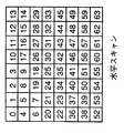
またさらに、上記画像予測符号化方法において、好ましくは、上記走査は、
(1)上記予測において上記カレントブロック(C)のAC係数が予測されていないときに、複数のDCT変換係数の8×8ブロックを以下の順序でジグザグ走査する場合と、
0, 1, 5, 6,14,15,27,28;
2, 4, 7,13,16,26,29,42;
3, 8,12,17,25,30,41,43;
9,11,18,24,31,40,44,53;
10,19,23,32,39,45,52,54;
20,22,33,38,46,51,55,60;
21,34,37,47,50,56,59,61;
35,36,48,49,57,58,62,63;
(2)上記予測において上記カレントブロック(C)のAC係数が予測され、上記DC予測が上記左ブロックを参照したときに、以下の順序で垂直走査をする場合と、
0, 4, 6,20,22,36,38,52;
1, 5, 7,21,23,37,39,53;
2, 8,19,24,34,40,50,54;
3, 9,18,25,35,41,51,55;
10,17,26,30,42,46,56,60;
11,16,27,31,43,47,57,61;
12,15,28,32,44,48,58,62;
13,14,29,33,45,49,59,63;
(3)上記予測において上記カレントブロック(C)のAC係数が予測され、上記DC予測が上記上ブロックを参照したときに、以下の順序で水平走査をする場合と、
0, 1, 2, 3,10,11,12,13;
4, 5, 8, 9,17,16,15,14;
6, 7,19,18,26,27,28,29;
20,21,24,25,30,31,32,33;
22,23,34,35,42,43,44,45;
36,37,40,41,46,47,48,49;
38,39,50,51,56,57,58,59;
52,53,54,55,60,61,62,63;
の走査を実行することを特徴とする。
【0044】
また、上記画像予測符号化方法において、好ましくは、上記左ブロック(B)又は上記上ブロック(A)のいずれかから選択された隣接ブロックのDC係数から、上記カレントブロック(C)のDC係数を最少ビット使用規則に従って予測することを特徴とする。
【0045】
さらに、上記画像予測符号化方法において、好ましくは、上記カレントブロックのAC係数が上記隣接ブロックから予測されるか否かを示す、指示ビットを供給することをさらに含むことを特徴とする。
【0046】
第1の発明に係る画像予測符号化装置は、入力される符号化画像データを互いに隣接する複数の小領域の画像データに分割する分割手段と、
上記分割手段によって分割された互いに隣接する複数の小領域の画像データの中で処理対象の小領域の画像データを符号化するときに、上記処理対象の小領域の画像データに隣接する再生された再生小領域の画像データを上記処理対象の小領域の画面内予測小領域の画像データとし、上記画面内予測小領域の画像データを最適予測小領域の画像データとし、上記処理対象の小領域の画像データと上記最適予測小領域の画像データとの差分である差分小領域の画像データを生成する第1の生成手段と、
上記生成手段によって生成された差分小領域の画像データを符号化する符号化手段と、
上記符号化手段によって符号化された差分小領域の画像データを復号化する復号化手段と、
上記復号化手段によって復号化された差分小領域の画像データを上記最適予測小領域の画像データに加算することにより再生された再生小領域の画像データを生成する第2の生成手段とを備える。
【0047】
また、第2の発明に係る画像予測符号化装置は、入力された符号化画像データを互いに隣接する複数の小領域の画像データに分割する分割手段と、
上記分割手段によって分割された互いに隣接する複数の小領域の中で処理対象の小領域を符号化するときに、上記処理対象の小領域の画像データに隣接する再生された再生小領域の画像データの中から、上記符号化画像データが有意であるか否かを示す入力された有意信号によって示される有意な画像データのみを上記処理対象の小領域の画面内予測小領域の画像データとし、上記画面内予測小領域の画像データを最適予測小領域の画像データとし、上記処理対象の小領域の画像データと上記最適予測小領域の画像データとの差分である差分小領域の画像データを生成する第1の生成手段と、
上記第1の生成手段によって生成された差分小領域の画像データを符号化する符号化手段と、
上記符号化手段によって符号化された差分小領域の画像データを復号化する復号化手段と、
上記復号化手段によって復号化された差分小領域の画像データを上記最適予測小領域の画像データに加算することにより再生された再生小領域の画像データを生成する第2の生成手段とを備える。
【0048】
さらに、第3の発明に係る画像予測復号化装置は、入力された符号化された画像データ系列を解析して画像差分信号を出力する解析手段と、
上記解析手段から出力される差分画像信号から、再生差分小領域の画像データを復号化する復号化手段と、
所定の画面内予測小領域の画像データを生成するための画像データを格納するラインメモリと、
上記ラインメモリからの画像データに対して予測信号発生処理を実行することにより、上記再生差分小領域の画像データに隣接する再生された画像データを画面内予測小領域の画像データとし、上記画面内予測小領域の画像データを最適予測小領域の画像データとして出力する発生手段と、
上記復号化手段からの再生差分小領域の画像データと、上記発生手段からの最適予測小領域の画像データとを加算して、加算結果の画面内予測小領域を生成するための画像データを出力するとともに、上記ラインメモリに格納する加算手段とを備える。
【0049】
またさらに、第4の発明に係る画像予測復号化装置は、入力された符号化された画像データ系列を解析して、画像差分信号と、動きベクトル信号と、制御信号とを出力する解析手段と、
上記解析手段から出力される差分画像信号を、再生差分小領域の画像データに復号化する復号化手段と、
上記解析手段から出力される制御信号に基づいて、動き補償手段と発生手段とが選択的に動作させるように制御する切り換え信号を出力する制御手段と、
所定の再生画像データを格納するフレームメモリと、
所定の画面内予測小領域の画像データを生成するための画像データを格納するラインメモリと、
上記制御手段からの切り換え信号に応答して、入力される動きベクトル信号に対して動き補償処理を実行することにより、上記フレームメモリから時間予測小領域の画像データを生成して、最適予測小領域の画像データとして出力する動き補償手段と、
上記制御手段からの切り換え信号に応答して、上記ラインメモリからの画像データに対して予測信号発生処理を実行することにより、上記再生差分小領域の画像データに隣接する再生された画像データを画面内予測小領域の画像データとし、上記画面内予測小領域の画像データを最適予測小領域の画像データとして出力する発生手段と、
上記復号化手段からの再生差分小領域の画像データと、上記発生手段からの最適予測小領域とを加算することにより、加算結果の再生画像データを出力するとともに、上記再生画像データを上記フレームメモリに格納し、上記画面内予測小領域の画像データを生成するための画像データのみを上記ラインメモリに格納する加算手段とを備える。
【0050】
また、第5の発明に係る画像予測復号化装置は、入力された符号化された画像データ系列を解析して、圧縮形状信号と画像差分信号とを出力する解析手段と、上記解析手段から出力される圧縮形状信号を、再生形状信号に復号化する第1の復号化手段と、
上記解析手段から出力される差分画像信号を、再生差分小領域の画像データに復号化する第2の復号化手段と、
所定の画面内予測小領域の画像データを生成するための画像データを格納するラインメモリと、
上記ラインメモリからの画像データに対して予測信号処理を実行することにより、上記再生差分小領域の画像データに隣接する再生された画像データの中から、上記再生形状信号によって示される有意な画像データのみを画面内予測小領域の画像データとし、上記画面内予測小領域の画像データを最適予測小領域の画像データとして出力する発生手段と、
上記第2の復号化手段からの再生差分小領域の画像データと、上記発生手段からの最適予測小領域とを加算することにより、加算結果の画像データを出力するとともに、上記画面内予測小領域の画像データを生成するための画像データのみを上記ラインメモリに格納する加算手段とを備える。
【0051】
さらに、第6の発明に係る画像予測復号化装置は、入力された符号化された画像データ系列を解析して、圧縮形状信号と、画像差分信号と、動きベクトル信号と、制御信号とを出力する解析手段と、
上記解析手段から出力される圧縮形状信号を、再生形状信号に復号化する第1の復号化手段と、
上記解析手段から出力される差分画像信号を、再生差分小領域に復号化する第2の復号化手段と、
上記解析手段から出力される制御信号に基づいて、動き補償手段と発生手段とを選択的に動作させるように制御する切り換え信号を出力する制御手段と、
所定の再生画像データを格納するフレームメモリと、
所定の画面内予測小領域の画像データを生成するための画像データを格納するラインメモリと、
上記制御手段から出力される切り換え信号に応答して、上記解析手段から出力される動きベクトル信号に基づいて、上記フレームメモリからの再生画像データに対して動き補償処理を実行することにより、時間予測小領域の画像データを発生して、最適予測小領域の画像データとして出力する動き補償手段と、
上記制御手段から出力される切り換え信号に応答して、上記ラインメモリからの画像データに対して予測信号処理を実行することにより、上記再生差分小領域の画像データに隣接する再生された画像データの中から、上記再生形状信号によって示される有意な画像データのみを画面内予測小領域の画像データとし、上記画面内予測小領域の画像データを最適予測小領域の画像データとして出力する発生手段と、
上記第2の復号化手段からの再生差分小領域の画像データと、上記発生手段からの最適予測小領域とを加算することにより、加算結果の再生画像データを出力するとともに、上記再生画像データを上記フレームメモリに格納し、上記画面内予測小領域を生成するための画像データのみを上記ラインメモリに格納する加算手段とを備える。
【0052】
第7の発明に係る画像予測符号化装置は、入力された画像信号をそれぞれ二次元配列の画素値を含む複数のブロックの画像データにサンプリングするサンプリング手段と、
上記サンプリング手段によってサンプリングされたブロックの画像データを所定の変換領域の係数データに変換する変換手段と、
復元されたブロックの係数データを格納するブロックメモリと、
上記ブロックメモリに格納された前に再構築されたブロックの係数データに基づいて、上記変換手段によって変換されたブロックの係数データに対して複数の予測ブロックの係数データを形成する予測手段と、
上記予測手段によって形成された複数の予測ブロックの係数データのうち、最も効率が良い予測ブロックの係数データを決定し選択して出力し、上記選択された予測ブロックを表す指示子を指示ビットの形式で画像予測復号化装置に送信する決定手段と、
上記決定手段によって選択された予測ブロックの係数データを、現時点のカレントブロックの係数データから減算することにより、減算結果の予測誤差の係数データを出力する第1の加算手段と、
上記第1の加算手段から出力される予測誤差の係数データを量子化する量子化手段と、
上記量子化手段からの予測誤差の係数データをエントロピー符号化して、符号化された予測誤差の係数データを画像予測復号化装置に送信する符号化手段と、
上記量子化手段からの予測誤差の係数データを逆量子化して、復元されたブロックの係数データを出力する逆量子化手段と、
上記決定手段から出力される予測ブロックの係数データを、上記逆量子化手段から出力される予測誤差の係数データに加算することにより、復元されたブロックの係数データを出力するとともに、上記ブロックメモリに格納する第2の加算手段と、
上記第2の加算手段から出力されるブロックの係数データを逆変換することにより、復元されたブロックの画像データを生成する逆変換手段とを備える。
【0053】
また、第8の発明に係る画像予測符号化装置は、入力された画像信号を二次元配列の画素値を含む複数のブロックの画像データにサンプリングするサンプリング手段と、
上記サンプリング手段によってサンプリングされた複数のブロックの画像データを所定の変換領域の係数データに変換する変換手段と、
上記変換手段からの変換領域の係数データを量子化する量子化手段と、
復元されたブロックの係数データを格納するブロックメモリと、
上記ブロックメモリに格納された前に再構築されたブロックの係数データに基づいて、上記変換手段によって変換されたブロックの係数データに対して複数の予測ブロックの係数データを形成する予測手段と、
上記予測手段によって形成された複数の予測ブロックの係数データのうち、最も効率が良い予測ブロックの係数データを決定し選択して出力し、上記選択された予測ブロックを表す指示子を指示ビットの形式で画像予測復号化装置に送信する決定手段と、
上記決定手段によって選択された予測ブロックの係数データを、現時点のカレントブロックの係数データから減算することにより、減算結果の予測誤差の係数データを出力する第1の加算手段と、
上記第1の加算手段からの予測誤差の係数データをエントロピー符号化して、符号化された予測誤差の係数データを画像予測復号化装置に送信する符号化手段と、
上記第1の加算手段からの予測誤差の係数データを、上記決定手段から出力される予測ブロックの係数データを加算することにより、量子化されたカレントブロックの係数データを復元して出力するとともに、上記ブロックメモリに格納する第2の加算手段と、
上記第2の加算手段から出力されるカレントブロックの係数データを逆量子化して出力する逆量子化手段と、
上記逆量子化手段からのカレントブロックの係数データを逆変換することにより、復元されたブロックの画像データを生成する逆変換手段とを備える。
【0054】
さらに、第9の発明に係る画像予測符号化装置は、入力された画像信号をそれぞれ二次元配列の画素値を含む複数のブロックの画像データにサンプリングするサンプリング手段と、
入力されるブロックの画像データに対して動き補償処理を実行することにより、動き補償されたブロックの予測誤差の画像データを生成して出力する補償手段と、
上記サンプリング手段から出力されるブロックの画像データから、上記補償手段から出力されるブロックの予測誤差の画像データを減算して、減算結果のブロックの画像データを出力する第1の加算手段と、
上記第1の加算手段から出力されるブロックの画像データを所定の変換領域の係数データに変換する変換手段と、
復元されたブロックの係数データを格納するブロックメモリと、
上記ブロックメモリに格納された前に再構築されたブロックの係数データに基づいて、上記変換手段によって変換されたブロックの係数データに対して複数の予測ブロックの係数データを形成する予測手段と、
上記予測手段によって形成された複数の予測ブロックの係数データのうち、最も効率が良い予測ブロックの係数データを決定し選択して出力し、上記選択された予測ブロックを表す指示子を指示ビットの形式で画像予測復号化装置に送信する決定手段と、
上記決定手段によって選択された予測ブロックの係数データを、現時点のカレントブロックの係数データから減算することにより、減算結果の予測誤差の係数データを出力する第2の加算手段と、
上記第2の加算手段から出力される予測誤差の係数データを量子化する量子化手段と、
上記量子化手段からの予測誤差の係数データをエントロピー符号化して、符号化された予測誤差の係数データを画像予測復号化装置に送信する符号化手段と、
上記量子化手段からの予測誤差の係数データを逆量子化して、復元されたブロックの係数データを出力する逆量子化手段と、
上記決定手段から出力される予測ブロックの係数データを、上記逆量子化手段から出力される予測誤差の係数データに加算することにより、復元されたブロックの係数データを出力するとともに、上記ブロックメモリに格納する第3の加算手段と、
上記第3の加算手段から出力されるブロックの係数データを逆変換することにより、復元されたブロックの画像データを生成する逆変換手段と、
上記逆変換手段からの復元されたブロックの画像データに、上記補償手段から出力される動き補償されたブロックの予測誤差の画像データを加算することにより、復元されたブロックの画像データを上記補償手段に出力する第4の加算手段とを備える。
【0055】
またさらに、第10の発明に係る画像予測符号化装置は、入力された画像信号を二次元配列の画素値を含む複数のブロックの画像データにサンプリングするサンプリング手段と、
入力されるブロックの画像データに対して動き補償処理を実行することにより、動き補償されたブロックの予測誤差の画像データを生成して出力する補償手段と、
上記サンプリング手段から出力されるブロックの画像データから、上記補償手段から出力されるブロックの予測誤差の画像データを減算して、減算結果のブロックの画像データを出力する第1の加算手段と、
上記第1の加算手段から出力されるブロックの画像データを所定の変換領域の係数データに変換する変換手段と、
上記変換手段からの変換領域の係数データを量子化する量子化手段と、
復元されたブロックの係数データを格納するブロックメモリと、
上記ブロックメモリに格納された前に再構築されたブロックの係数データに基づいて、上記変換手段によって変換されたブロックの係数データに対して複数の予測ブロックの係数データを形成する予測手段と、
上記予測手段によって形成された複数の予測ブロックの係数データのうち、最も効率が良い予測ブロックの係数データを決定し選択して出力し、上記選択された予測ブロックを表す指示子を指示ビットの形式で画像予測復号化装置に送信する決定手段と、
上記決定手段によって選択された予測ブロックの係数データを、現時点のカレントブロックの係数データから減算することにより、減算結果の予測誤差の係数データを出力する第2の加算手段と、
上記第2の加算手段からの予測誤差の係数データをエントロピー符号化して、符号化された予測誤差の係数データを画像予測復号化装置に送信する符号化手段と、
上記第2の加算手段からの予測誤差の係数データを、上記決定手段から出力される予測ブロックの係数データを加算することにより、量子化されたカレントブロックの係数データを復元して出力するとともに、上記ブロックメモリに格納する第3の加算手段と、
上記第3の加算手段から出力されるカレントブロックの係数データを逆量子化して出力する逆量子化手段と、
上記逆量子化手段からのカレントブロックの係数データを逆変換することにより、復元されたブロックの画像データを生成する逆変換手段と、
上記逆変換手段からの復元されたブロックの画像データに、上記補償手段から出力される動き補償されたブロックの予測誤差の画像データを加算することにより、復元されたブロックの画像データを上記補償手段に出力する第4の加算手段とを備える。
【0056】
第11の発明に係る画像予測復号化装置は、第7の発明に係る画像予測符号化装置に対応して設けられる画像予測復号化装置であって、
上記画像予測符号化装置から受信された受信データから指示ビットを抽出する抽出手段と、
復元されたブロックの係数データを格納するブロックメモリと、
上記抽出手段によって抽出された指示ビットが示す予測ブロックに基づいて、上記ブロックメモリに格納された以前に復元されたブロックの係数データを用いて、上記受信データに含まれる現時点のカレントブロックの係数データに対して予測ブロックの係数データを生成して出力する別の予測手段と、
上記受信データをエントロピー復号化して、復号化された予測誤差の係数データを出力する復号化手段と、
上記復号化手段から出力される予測誤差の係数データを逆量子化して出力する逆量子化手段と、
上記別の予測手段から出力される予測ブロックの係数データを、上記逆量子化手段から出力される予測誤差の係数データに加算することにより、現時点のカレントブロックの係数データを復元して出力するとともに、上記ブロックメモリに格納する第3の加算手段と、
上記第3の加算手段から出力されるカレントブロックの係数データを逆変換して、復元されたカレントブロックの画像データを出力する別の逆変換手段とを備える。
【0057】
また、第12の発明に係る画像予測復号化装置は、第8の発明に係る画像予測符号化装置に対応して設けられる画像予測復号化装置であって、
上記画像予測符号化装置から受信された受信データから指示ビットを抽出する抽出手段と、
復元されたブロックの係数データを格納するブロックメモリと、
上記抽出手段によって抽出された指示ビットが示す予測ブロックに基づいて、上記ブロックメモリに格納された以前に復元されたブロックの係数データを用いて、上記受信データに含まれる現時点のカレントブロックの係数データに対して予測ブロックの係数データを生成して出力する別の予測手段と、
上記受信データをエントロピー復号化して、復号化された予測誤差の係数データを出力する復号化手段と、
上記予測手段から出力される予測ブロックの係数データを、上記復号化手段から出力される予測誤差の係数データに加算することにより、現時点のカレントブロックの係数データを復元して出力するとともに、上記ブロックメモリに格納する第3の加算手段と、
上記第3の加算手段から出力される予測誤差の係数データを逆量子化して出力する逆量子化手段と、
上記逆量子化手段から出力されるカレントブロックの係数データを逆変換して、復元されたカレントブロックの画像データを出力する別の逆変換手段とを備える。
【0058】
さらに、第13の発明に係る画像予測復号化装置は、第9の発明に係る画像予測符号化装置に対応して設けられる画像予測復号化装置であって、
上記画像予測符号化装置から受信された受信データから指示ビットを抽出する抽出手段と、
復元されたブロックの係数データを格納するブロックメモリと、
上記抽出手段によって抽出された指示ビットが示す予測ブロックに基づいて、上記ブロックメモリに格納された以前に復元されたブロックの係数データを用いて、上記受信データに含まれる現時点のカレントブロックの係数データに対して予測ブロックの係数データを生成して出力する別の予測手段と、
上記受信データをエントロピー復号化して、復号化された予測誤差の係数データを出力する復号化手段と、
上記復号化手段から出力される予測誤差の係数データを逆量子化して出力する逆量子化手段と、
上記別の予測手段から出力される予測ブロックの係数データを、上記逆量子化手段から出力される予測誤差の係数データに加算することにより、現時点のカレントブロックの係数データを復元して出力するとともに、上記ブロックメモリに格納する第3の加算手段と、
上記第3の加算手段から出力されるカレントブロックの係数データを逆変換して、復元されたカレントブロックの画像データを出力する別の逆変換手段と、
上記別の逆変換手段から出力されるカレントブロックの画像データに対して動き補償処理を実行することにより、動き補償の予測誤差データを出力する別の補償手段と、
上記別の逆変換手段から出力されるカレントブロックの画像データから、上記別の補償手段から出力される動き補償の予測誤差データを減算して、減算結果の復元されたブロックの画像データを出力する第5の加算手段とを備える。
【0059】
またさらに、第14の発明に係る画像予測復号化装置は、第10の発明に係る画像予測符号化装置に対応して設けられる画像予測復号化装置であって、
上記画像予測符号化装置から受信された受信データから指示ビットを抽出する抽出手段と、
復元されたブロックの係数データを格納するブロックメモリと、
上記抽出手段によって抽出された指示ビットが示す予測ブロックに基づいて、上記ブロックメモリに格納された以前に復元されたブロックの係数データを用いて、上記受信データに含まれる現時点のカレントブロックの係数データに対して予測ブロックの係数データを生成して出力する別の予測手段と、
上記受信データをエントロピー復号化して、復号化された予測誤差の係数データを出力する復号化手段と、
上記予測手段から出力される予測ブロックの係数データを、上記復号化手段から出力される予測誤差の係数データに加算することにより、現時点のカレントブロックの係数データを復元して出力するとともに、上記ブロックメモリに格納する第3の加算手段と、
上記第3の加算手段から出力される予測誤差の係数データを逆量子化して出力する逆量子化手段と、
上記逆量子化手段から出力されるカレントブロックの係数データを逆変換して、復元されたカレントブロックの画像データを出力する別の逆変換手段と、
上記別の逆変換手段から出力されるカレントブロックの画像データに対して動き補償処理を実行することにより、動き補償の予測誤差データを出力する別の補償手段と、
上記別の逆変換手段から出力されるカレントブロックの画像データから、上記別の補償手段から出力される動き補償の予測誤差データを減算して、減算結果の復元されたブロックの画像データを出力する第5の加算手段とを備える。
【0060】
第15の発明に係る画像予測符号化装置は、入力された画像信号をそれぞれ二次元配列の画素値を含む複数のブロックの画像データにサンプリングするサンプリング手段と、
上記サンプリング手段によってサンプリングされたブロックの画像データを所定の変換領域の係数データに変換する変換手段と、
復元されたブロックの係数データを格納するブロックメモリと、
上記ブロックメモリに格納された前に再構築されたブロックの係数データに基づいて、上記変換手段によって変換されたブロックの係数データに対して複数の予測ブロックの係数データを形成する予測手段と、
上記予測手段によって形成された複数の予測ブロックの係数データのうち、最も効率が良い予測ブロックの係数データ及びスキャン方法を決定し選択して出力し、上記選択された予測ブロック及びスキャン方法を表す指示子を指示ビットの形式で画像予測復号化装置に送信する決定手段と、
上記決定手段によって選択された予測ブロックの係数データを、現時点のカレントブロックの係数データから減算することにより、減算結果の予測誤差の係数データを出力する第1の加算手段と、
上記第1の加算手段から出力される予測誤差の係数データを量子化する量子化手段と、
上記量子化手段からの予測誤差の係数データに対して上記決定手段によって決定されたスキャン方法でスキャン処理を実行して、スキャン処理後の予測誤差の係数データを出力するスキャン手段と、
上記スキャン手段から出力されるスキャン処理後の予測誤差の係数データをエントロピー符号化して、符号化された予測誤差の係数データを画像予測復号化装置に送信する符号化手段と、
上記量子化手段からの予測誤差の係数データを逆量子化して、復元されたブロックの係数データを出力する逆量子化手段と、
上記決定手段から出力される予測ブロックの係数データを、上記逆量子化手段から出力される予測誤差の係数データに加算することにより、復元されたブロックの係数データを出力するとともに、上記ブロックメモリに格納する第2の加算手段と、
上記第2の加算手段から出力されるブロックの係数データを逆変換することにより、復元されたブロックの画像データを生成する逆変換手段とを備える。
【0061】
また、第16の発明に係る画像予測符号化装置は、入力された画像信号を二次元配列の画素値を含む複数のブロックの画像データにサンプリングするサンプリング手段と、
上記サンプリング手段によってサンプリングされた複数のブロックの画像データを所定の変換領域の係数データに変換する変換手段と、
上記変換手段からの変換領域の係数データを量子化する量子化手段と、
復元されたブロックの係数データを格納するブロックメモリと、
上記ブロックメモリに格納された前に再構築されたブロックの係数データに基づいて、上記変換手段によって変換されたブロックの係数データに対して複数の予測ブロックの係数データを形成する予測手段と、
上記予測手段によって形成された複数の予測ブロックの係数データのうち、最も効率が良い予測ブロックの係数データ及びスキャン方法を決定し選択して出力し、上記選択された予測ブロック及びスキャン方法を表す指示子を指示ビットの形式で画像予測復号化装置に送信する決定手段と、
上記決定手段によって選択された予測ブロックの係数データを、現時点のカレントブロックの係数データから減算することにより、減算結果の予測誤差の係数データを出力する第1の加算手段と、
上記第1の加算手段からの予測誤差の係数データに対して上記決定手段によって決定されたスキャン方法でスキャン処理を実行して、スキャン処理後の予測誤差の係数データを出力するスキャン手段と、
上記スキャン手段から出力されるスキャン処理後の予測誤差の係数データをエントロピー符号化して、符号化された予測誤差の係数データを画像予測復号化装置に送信する符号化手段と、
上記第1の加算手段からの予測誤差の係数データを、上記決定手段から出力される予測ブロックの係数データを加算することにより、量子化されたカレントブロックの係数データを復元して出力するとともに、上記ブロックメモリに格納する第2の加算手段と、
上記第2の加算手段から出力されるカレントブロックの係数データを逆量子化して出力する逆量子化手段と、
上記逆量子化手段からのカレントブロックの係数データを逆変換することにより、復元されたブロックの画像データを生成する逆変換手段とを備える。
さらに、第17の発明に係る画像予測符号化装置は、入力された画像信号をそれぞれ二次元配列の画素値を含む複数のブロックの画像データにサンプリングするサンプリング手段と、
入力されるブロックの画像データに対して動き補償処理を実行することにより、動き補償されたブロックの予測誤差の画像データを生成して出力する補償手段と、
上記サンプリング手段から出力されるブロックの画像データから、上記補償手段から出力されるブロックの予測誤差の画像データを減算して、減算結果のブロックの画像データを出力する第1の加算手段と、
上記第1の加算手段から出力されるブロックの画像データを所定の変換領域の係数データに変換する変換手段と、
復元されたブロックの係数データを格納するブロックメモリと、
上記ブロックメモリに格納された前に再構築されたブロックの係数データに基づいて、上記変換手段によって変換されたブロックの係数データに対して複数の予測ブロックの係数データを形成する予測手段と、
上記予測手段によって形成された複数の予測ブロックの係数データのうち、最も効率が良い予測ブロックの係数データ及びスキャン方法を決定し選択して出力し、上記選択された予測ブロック及びスキャン方法を表す指示子を指示ビットの形式で画像予測復号化装置に送信する決定手段と、
上記決定手段によって選択された予測ブロックの係数データを、現時点のカレントブロックの係数データから減算することにより、減算結果の予測誤差の係数データを出力する第2の加算手段と、
上記第2の加算手段から出力される予測誤差の係数データを量子化する量子化手段と、
上記量子化手段からの予測誤差の係数データに対して上記決定手段によって決定されたスキャン方法でスキャン処理を実行して、スキャン処理後の予測誤差の係数データを出力するスキャン手段と、
上記スキャン手段から出力されるスキャン処理後の予測誤差の係数データをエントロピー符号化して、符号化された予測誤差の係数データを画像予測復号化装置に送信する符号化手段と、
上記量子化手段からの予測誤差の係数データを逆量子化して、復元されたブロックの係数データを出力する逆量子化手段と、
上記決定手段から出力される予測ブロックの係数データを、上記逆量子化手段から出力される予測誤差の係数データに加算することにより、復元されたブロックの係数データを出力するとともに、上記ブロックメモリに格納する第3の加算手段と、
上記第3の加算手段から出力されるブロックの係数データを逆変換することにより、復元されたブロックの画像データを生成する逆変換手段と、
上記逆変換手段からの復元されたブロックの画像データに、上記補償手段から出力される動き補償されたブロックの予測誤差の画像データを加算することにより、復元されたブロックの画像データを上記補償手段に出力する第4の加算手段とを備える。
【0062】
またさらに、第18の発明に係る画像予測符号化装置は、入力された画像信号を二次元配列の画素値を含む複数のブロックの画像データにサンプリングするサンプリング手段と、
入力されるブロックの画像データに対して動き補償処理を実行することにより、動き補償されたブロックの予測誤差の画像データを生成して出力する補償手段と、
上記サンプリング手段から出力されるブロックの画像データから、上記補償手段から出力されるブロックの予測誤差の画像データを減算して、減算結果のブロックの画像データを出力する第1の加算手段と、
上記第1の加算手段から出力されるブロックの画像データを所定の変換領域の係数データに変換する変換手段と、
上記変換手段からの変換領域の係数データを量子化する量子化手段と、
復元されたブロックの係数データを格納するブロックメモリと、
上記ブロックメモリに格納された前に再構築されたブロックの係数データに基づいて、上記変換手段によって変換されたブロックの係数データに対して複数の予測ブロックの係数データを形成する予測手段と、
上記予測手段によって形成された複数の予測ブロックの係数データのうち、最も効率が良い予測ブロックの係数データ及びスキャン方法を決定し選択して出力し、上記選択された予測ブロック及びスキャン方法を表す指示子を指示ビットの形式で画像予測復号化装置に送信する決定手段と、
上記決定手段によって選択された予測ブロックの係数データを、現時点のカレントブロックの係数データから減算することにより、減算結果の予測誤差の係数データを出力する第2の加算手段と、
上記第2の加算手段からの予測誤差の係数データに対して上記決定手段によって決定されたスキャン方法でスキャン処理を実行して、スキャン処理後の予測誤差の係数データを出力するスキャン手段と、
上記スキャン手段から出力されるスキャン処理後の予測誤差の係数データをエントロピー符号化して、符号化された予測誤差の係数データを画像予測復号化装置に送信する符号化手段と、
上記第2の加算手段からの予測誤差の係数データを、上記決定手段から出力される予測ブロックの係数データを加算することにより、量子化されたカレントブロックの係数データを復元して出力するとともに、上記ブロックメモリに格納する第3の加算手段と、
上記第3の加算手段から出力されるカレントブロックの係数データを逆量子化して出力する逆量子化手段と、
上記逆量子化手段からのカレントブロックの係数データを逆変換することにより、復元されたブロックの画像データを生成する逆変換手段と、
上記逆変換手段からの復元されたブロックの画像データに、上記補償手段から出力される動き補償されたブロックの予測誤差の画像データを加算することにより、復元されたブロックの画像データを上記補償手段に出力する第4の加算手段とを備える。
【0063】
第19の発明に係る画像予測復号化装置は、第15の発明に係る画像予測符号化装置に対応して設けられる画像予測復号化装置であって、
上記画像予測符号化装置から受信された受信データから指示ビットを抽出する抽出手段と、
復元されたブロックの係数データを格納するブロックメモリと、
上記抽出手段によって抽出された指示ビットが示す予測ブロックに基づいて、上記ブロックメモリに格納された以前に復元されたブロックの係数データを用いて、上記受信データに含まれる現時点のカレントブロックの係数データに対して予測ブロックの係数データを生成して出力する別の予測手段と、
上記受信データをエントロピー復号化して、復号化された予測誤差の係数データを出力する復号化手段と、
上記復号化手段から出力される予測誤差の係数データに対して、上記上記抽出手段によって抽出された指示ビットが示すスキャン方法に基づいて、逆スキャン処理を実行して、逆スキャン処理後の予測誤差の係数データを出力する逆スキャン手段と、
上記逆スキャン手段から出力される逆スキャン処理後の予測誤差の係数データを逆量子化して出力する逆量子化手段と、
上記別の予測手段から出力される予測ブロックの係数データを、上記逆量子化手段から出力される予測誤差の係数データに加算することにより、現時点のカレントブロックの係数データを復元して出力するとともに、上記ブロックメモリに格納する第3の加算手段と、
上記第3の加算手段から出力されるカレントブロックの係数データを逆変換して、復元されたカレントブロックの画像データを出力する別の逆変換手段とを備える。
【0064】
また、第20の発明に係る画像予測復号化装置は、第16の発明に係る画像予測符号化装置に対応して設けられる画像予測復号化装置であって、
上記画像予測符号化装置から受信された受信データから指示ビットを抽出する抽出手段と、
復元されたブロックの係数データを格納するブロックメモリと、
上記抽出手段によって抽出された指示ビットが示す予測ブロックに基づいて、上記ブロックメモリに格納された以前に復元されたブロックの係数データを用いて、上記受信データに含まれる現時点のカレントブロックの係数データに対して予測ブロックの係数データを生成して出力する別の予測手段と、
上記受信データをエントロピー復号化して、復号化された予測誤差の係数データを出力する復号化手段と、
上記復号化手段から出力される予測誤差の係数データに対して、上記上記抽出手段によって抽出された指示ビットが示すスキャン方法に基づいて、逆スキャン処理を実行して、逆スキャン処理後の予測誤差の係数データを出力する逆スキャン手段と、
上記予測手段から出力される予測ブロックの係数データを、上記逆スキャン手段から出力される予測誤差の係数データに加算することにより、現時点のカレントブロックの係数データを復元して出力するとともに、上記ブロックメモリに格納する第3の加算手段と、
上記第3の加算手段から出力される予測誤差の係数データを逆量子化して出力する逆量子化手段と、
上記逆量子化手段から出力されるカレントブロックの係数データを逆変換して、復元されたカレントブロックの画像データを出力する別の逆変換手段とを備える。
【0065】
さらに、第21の発明に係る画像予測復号化装置は、第17の発明に係る画像予測符号化装置に対応して設けられる画像予測復号化装置であって、
上記画像予測符号化装置から受信された受信データから指示ビットを抽出する抽出手段と、
復元されたブロックの係数データを格納するブロックメモリと、
上記抽出手段によって抽出された指示ビットが示す予測ブロックに基づいて、上記ブロックメモリに格納された以前に復元されたブロックの係数データを用いて、上記受信データに含まれる現時点のカレントブロックの係数データに対して予測ブロックの係数データを生成して出力する別の予測手段と、
上記受信データをエントロピー復号化して、復号化された予測誤差の係数データを出力する復号化手段と、
上記復号化手段から出力される予測誤差の係数データに対して、上記上記抽出手段によって抽出された指示ビットが示すスキャン方法に基づいて、逆スキャン処理を実行して、逆スキャン処理後の予測誤差の係数データを出力する逆スキャン手段と、
上記逆スキャン手段から出力される逆スキャン処理後の予測誤差の係数データを逆量子化して出力する逆量子化手段と、
上記別の予測手段から出力される予測ブロックの係数データを、上記逆量子化手段から出力される予測誤差の係数データに加算することにより、現時点のカレントブロックの係数データを復元して出力するとともに、上記ブロックメモリに格納する第3の加算手段と、
上記第3の加算手段から出力されるカレントブロックの係数データを逆変換して、復元されたカレントブロックの画像データを出力する別の逆変換手段と、
上記別の逆変換手段から出力されるカレントブロックの画像データに対して動き補償処理を実行することにより、動き補償の予測誤差データを出力する別の補償手段と、
上記別の逆変換手段から出力されるカレントブロックの画像データから、上記別の補償手段から出力される動き補償の予測誤差データを減算して、減算結果の復元されたブロックの画像データを出力する第5の加算手段とを備える。
またさらに、第22の発明に係る画像予測復号化装置は、第18の発明に係る画像予測符号化装置に対応して設けられる画像予測復号化装置であって、
上記画像予測符号化装置から受信された受信データから指示ビットを抽出する抽出手段と、
復元されたブロックの係数データを格納するブロックメモリと、
上記抽出手段によって抽出された指示ビットが示す予測ブロックに基づいて、上記ブロックメモリに格納された以前に復元されたブロックの係数データを用いて、上記受信データに含まれる現時点のカレントブロックの係数データに対して予測ブロックの係数データを生成して出力する別の予測手段と、
上記受信データをエントロピー復号化して、復号化された予測誤差の係数データを出力する復号化手段と、
上記復号化手段から出力される予測誤差の係数データに対して、上記上記抽出手段によって抽出された指示ビットが示すスキャン方法に基づいて、逆スキャン処理を実行して、逆スキャン処理後の予測誤差の係数データを出力する逆スキャン手段と、
上記予測手段から出力される予測ブロックの係数データを、上記逆スキャン手段から出力される予測誤差の係数データに加算することにより、現時点のカレントブロックの係数データを復元して出力するとともに、上記ブロックメモリに格納する第3の加算手段と、
上記第3の加算手段から出力される予測誤差の係数データを逆量子化して出力する逆量子化手段と、
上記逆量子化手段から出力されるカレントブロックの係数データを逆変換して、復元されたカレントブロックの画像データを出力する別の逆変換手段と、
上記別の逆変換手段から出力されるカレントブロックの画像データに対して動き補償処理を実行することにより、動き補償の予測誤差データを出力する別の補償手段と、
上記別の逆変換手段から出力されるカレントブロックの画像データから、上記別の補償手段から出力される動き補償の予測誤差データを減算して、減算結果の復元されたブロックの画像データを出力する第5の加算手段とを備える。
【0066】
また、第23の発明に係る画像予測符号化方法は、上記画像予測符号化装置における各手段をそれぞれ各ステップに置き換えたステップを含む。
【0067】
さらに、第24の発明に係る画像予測復号化方法は、上記画像予測復号化装置における各手段をそれぞれ各ステップに置き換えたステップを含む。
【0068】
また、第25の発明に係る記録媒体は、上記画像予測符号化方法における各ステップを含むプログラムを記録した記録媒体である。
【0069】
さらに、第26の発明に係る記録媒体は、上記画像予測復号化方法における各ステップを含むプログラムを記録した記録媒体である。
【0070】
【発明の実施の形態】
以下、本発明に係る好ましい実施形態について、添付の図面を参照して説明する。
【0071】
<第1の実施形態グループ>
第1の実施形態グループは、第1の乃至第4の実施形態を含む。
【0072】
<第1の実施形態>
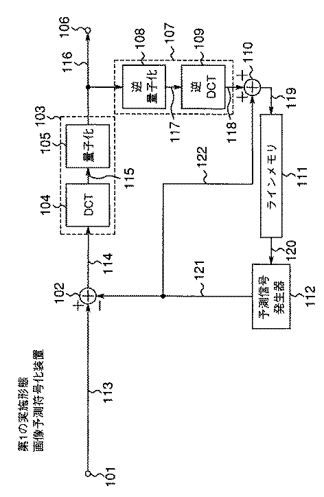
図1は、本発明に係る第1の実施形態である画像予測符号化装置の構成を示すブロック図である。
【0073】
図1において、101は入力端子、102は第1の加算器、103は符号化器、106は出力端子、107は復号化器、110は第2の加算器、111はラインメモリ、112は予測信号発生器である。
【0074】
以下、画像予測符号化装置の構成及び動作について説明する。入力端子101に、符号化の処理対象となる画像データが入力される。ここで、入力された画像データは複数の隣接する小領域に分割される。
【0075】
図2において、8×8の小領域に分割された場合の入力された画像データの画像を示し、図3において、三角形小領域に分割された場合の入力された画像データの画像を示す。複数の小領域の画像データを順次に符号化するが、処理対象の小領域の画像データは、入力端子101及びライン113を介して加算器102に入力される。一方、予測信号発生器112は、画面内予測小領域の画像データを発生し、発生された画像データを最適予測小領域の画像データとして、ライン121を介して加算器102に出力する。
【0076】
加算器102は、処理対象の小領域における入力された画像データの画素値から、予測信号発生器112からの最適予測小領域の対応する画素値を減算し、減算結果の差分小領域の画像データを生成して符号化器103に出力して、圧縮符号化処理を実行する。本実施形態では、符号化器103はDCT変換器104と量子化器(Q)105を備え、差分小領域の画像データは、DCT変換器104によって周波数領域の画像信号に変換され、DCT変換係数を得る。次いで、DCT変換係数は、量子化器105によって量子化される。量子化された小領域の画像データはライン116を介して出力端子106に出力され、さらに可変長又は固定長の符号に変換された後、例えば光ディスクなどの記録媒体に記憶され又は通信回線を介して伝送される(図示せず。)。
【0077】
同時に、量子化された小領域の画像データは復号化器107に入力され、ここで、当該復号化器107は、逆量子化器108と逆DCT変換器109とを備え、入力された小領域の画像データを、伸長差分小領域の画像データに復元する。本実施形態では、入力された小領域の画像データは、逆量子化器108によって逆量子化された後、逆量子化された画像データは、逆離散コサイン変換器(以下、逆DCT変換器という。)109によって空間領域の画像信号に変換される。このように得られた伸長差分小領域の画像データは加算器110に出力され、加算器110は、伸長差分小領域の画像データに、予測信号発生器112からライン121とライン122を介して出力される最適予測画像信号を加算して、再生小領域の画像データを生成し、再生小領域の画像データの中から、画面内予測画像信号を生成するための再生画素値をラインメモリ111に格納する。予測信号発生器112は以下のように、画面内予測小領域の画像データを発生する。すなわち、予測信号発生器112は、処理対象の小領域の画像データに隣接する再生された画像データの画素値を、画面内予測小領域の画像データの画素値として発生する。
【0078】
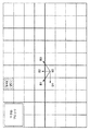
図2において、ブロック200を処理対象の小領域とすると、隣接する再生された画像データの画素値はa0、a1、a2、…、a6、a7、b0、b1、b2、…、b6、b7である。図3において、三角形301を処理対象の小領域とすると、隣接する再生された画像データの画素値はg0、g1、…、g4、f0、f1、f2、…、f7、f8である。また、図3の三角形300を処理対象の小領域とすると、隣接する再生された画像データの画素値はe0、h0、h1、…、h4である。これらの画素値をラインメモリ111に格納する。予測信号発生器112はラインメモリ111をアクセスし隣接する画像データの画素値を画面内予測小領域の画像データの画素値として読み出す。
【0079】
図4及び図5はそれぞれ、図1の画像予測符号化装置に用いられる予測信号発生器の第1及び第2の実施例の構成を示すブロック図である。
【0080】
図4において、処理対象の小領域に対して水平方向に隣接する画素値a0、a1、a2、…、a6、a7はラインメモリ111から予測信号発生器112に入力され、予測信号発生器112内の発生器401は、水平方向に同一の画素を例えば8回繰り返して出力することにより、画面内予測小領域の画像データ403を生成する。ここで、画面内予測小領域の画像データ403は処理対象の小領域に対して垂直方向に隣接する画素が存在しない場合に用いられる。
【0081】
図5において、処理対象の小領域に対して垂直方向に隣接する画素値b0、b1、b2、…、b6、b7がラインメモリ111から予測信号発生器112に入力され、予測信号発生器112内の発生器402は、垂直方向に画素を例えば8回繰り返して出力することにより、画面内予測小領域の画像データ404を生成する。ここで、画面内予測小領域の画像データ404は、処理対象の小領域に対して水平方向に隣接する画素がない場合に用いられる。水平方向及び垂直方向共に隣接する画素値が存在する場合、図6に示す第3の実施例のように画面内予測小領域の画像データを生成する。
【0082】
図6は、図1の画像予測符号化装置に用いられる予測信号発生器の第3の実施例の構成を示すブロック図である。
【0083】
図6において、発生器401によって発生された画面内予測小領域の画像データ403(図5参照。)と、発生器402によって発生された画面内予測小領域の画像データ404とは加算器500に入力され、加算器500は、入力された2つの画像データの和を2で除算することにより、これら2つの画像データを平均化する。このように、発生器401,402により隣接する再生された画素を繰り返して出力し、加算器500により平均化演算を行うだけなので、画面内予測小領域の画像データを高速に生成することができる。なお、隣接する2つの画像データの画素値を線形補間することにより画面内予測小領域の画像データを生成してもよい。
【0084】
図7は、図1の画像予測符号化装置に用いられる予測信号発生器の第4の実施例の構成を示すブロック図である。
【0085】
図7において、処理対象の小領域に対して水平方向に隣接する画像データの画素値a0、a1、a2、…、a6、a7は、ラインメモリ111から発生器401に入力され、発生器401は、水平方向に画素を繰り返して出力することにより第1の画面内予測小領域の画像データを生成する。一方、処理対象の小領域に対して垂直方向に隣接する画素値b0、b1、b2、…、b6、b7は、ラインメモリ111から発生器402に入力され、発生器402は、垂直方向に画素を繰り返して出力することにより第2の画面内予測小領域の画像データを生成する。第1の画面内予測小領域の画像データと、第2の画面内予測小領域の画像データは加算器500に入力され、これら2つの画像データを平均化することにより第3の画面内予測小領域の画像データを生成する。
【0086】
一方、処理対象の小領域の画像データは、ライン616を介して誤差計算器601,602,603に入力される。ここで、上記第1の画面内予測小領域の画像データと、処理対象の小領域の画像データは、誤差計算器601に入力され、誤差計算器601はそれら2つの画像データの誤差の絶対値である第1の絶対誤差を計算して比較器604に出力する。また、上記第2の画面内予測小領域の画像データと、処理対象の小領域の画像データは誤差計算器602に入力され、誤差計算器602はこれら2つの画像データの誤差の絶対値である第2の絶対誤差を計算して比較器604に出力する。さらに、上記第3の画面内予測小領域の画像データと、処理対象の小領域の画像データは、誤差計算器603に入力され、誤差計算器603はこれら2つの画像データの誤差の絶対値である第3の絶対誤差を計算して比較器604に出力する。
【0087】
比較器604は、入力される3つの絶対誤差を互いに比較して、絶対誤差の最も小さいものを決定し、それに対応する画面内予測小領域の画像データをライン121に出力するようにスイッチ605を制御する。比較器604は、同時に、第1、第2及び第3の画面内予測小領域の画像データを識別するための識別子をライン615を介して受信側又は再生側の装置に出力する。この識別子により、受信側又は再生側では画面内予測小領域の画像データが一意に決まる。このように誤差の最も小さい画面内予測小領域の画像データを用いることによって、符号化時の差分信号を抑圧することができ、発生ビット数を削減することができる。
【0088】
<第2の実施形態>
図8は、本発明に係る第2の実施形態である画像予測符号化装置の構成を示すブロック図であり、図1と同様のものは同一の符号を付している。 図8の画像予測符号化装置は、図1の画像予測符号化装置に比較して、動き検出器700、動き補償器701、最適モード選択器703とフレームメモリ702を追加して備えたことを特徴とする。
【0089】
以下、図8の画像予測符号化装置の構成及び動作について説明する。
【0090】
入力端子101を介して、第1の実施形態と同様に、入力された処理対象の小領域の画像データが加算器102に入力され、加算器102は、処理対象の小領域の画像データを、最適モード選択器703からライン121を介して入力される最適予測小領域の画像データから減算した後、減算結果の画像データを符号化器103に出力する。符号化器103は、入力される減算結果の画像データを圧縮符号化して出力端子106を介して出力すると同時に、圧縮符号化された小領域の画像データを復号化器107に出力して伸長復号化させた後、加算器110に出力して、伸長復号化された画像データを最適予測小領域の画像データと加算する。
【0091】
次いで、第1の実施形態と同様に、画面内予測小領域の画像データを生成するために用いられる画像データの画素値のみをラインメモリ111に格納する一方、再生された画像の画素値をすべてフレームメモリ702に格納する。
【0092】
次の画像の画像データが入力端子101を介して入力されるときに、動き検出器700には、処理対象の小領域の画像データと、フレームメモリ702に格納された再生画像データとが入力され、動き検出器700は、ブロックマッチングなどの方法で画像の動きを検出し、動きベクトルをライン705を介して出力する。出力された動きベクトルは、例えば可変長符号化して記憶又は伝送される(図示せず。)と同時に動き補償器701に送られる。動き補償器701は、動きベクトルに基づいてフレームメモリ702の再生画像から時間予測小領域の画像データを生成して、最適モード選択器703に出力する。動き検出処理及び動き補償処理においては、前方予測と、後方予測と、両方向予測とがあり、これらの方法は、例えば米国特許第5,193,004号明細書に開示されている。
【0093】
一方、予測信号発生器112は、第1の実施形態と同様に、画面内予測小領域の画像データを発生して最適モード選択器703に出力すると同時に、処理対象の小領域の画像データを最適モード選択器703に出力する。最適モード選択器703は、画面内予測小領域の画像データと、時間予測小領域の画像データとから、処理対象の小領域の画像データに最も誤差(例えば、画素毎の差の絶対値の和)の小さい画像データを選択し、選択された画像データを最適予測小領域の画像データとして加算器102に出力する。また、どの予測小領域の画像データが選択されたかを示す識別子をライン709を介して受信側又は再生側に出力して伝送する。
【0094】
このようにフレーム間動き補償符号化の画像データに、画面内予測を導入することによりフレーム間の動きベクトルを伝送する必要がないため、ビット数をさらに削減できる。
【0095】
第1と第2の実施形態では、画面全体に有意な画素が存在する場合である。画面内に有意であるとそうでない画素が存在する場合がある。例えば、クロマキーで撮影された画像では、被写体を表す画素は有意なもので、背景となるブルーなど領域を現す画素は有意でない画素である。有意な物体のテキスチャー及びその形状を符号化して伝送することにより、物体単位の再生表示が可能である。このような入力画像に対して、予測信号発生器112で画面内予測小領域の画像データを生成する場合、有意でない画素値を用いることができない。
【0096】
図9乃至図11は有意な画素と有意でない画素をもつ入力画像の模式図を示す。本実施形態においては、画素が有意であるかどうかを示すには形状信号を用いる。形状信号を所定の方法で圧縮符号化して受信側又は再生側に伝送する。形状を符号化する方法としては、チェーン符号化などの方法がある。圧縮された形状信号をまた伸長再生し、再生された形状信号を用いて以下に述べるように画面内予測信号を生成する。
【0097】
図9においては、形状曲線800が境界線で、矢印の示す方向が物体の内部であって、物体の内部の画像データは有意な画素から構成される。処理対象の小領域802に隣接する再生された画素の中で、b4、b5、b6、b7が有意な画素で、これらの画素値のみを繰り返して処理対象の小領域802の画面内予測小領域の画素値とする。
【0098】
また、図10においては、形状曲線804が境界線で、矢印の示す方向が物体の内部であって、物体の内部の画像データは有意な画素から構成される。処理対象の小領域805に隣接する再生された画素の中で、a4、a5、a6、a7が有意な画素であって、これらの画素値のみを繰り返して処理対象の小領域805の画面内予測小領域の画素値とする。
【0099】
さらに、図11においては、曲線808が境界線で、矢印の示す方向が物体の内部であって、物体の内部の画像データは有意な画素から構成される。処理対象の小領域810に隣接する再生された画素の中で、a5、a6、a7、b4、b5、b6、b7が有意な画素であって、これらの画素値のみを繰り返して出力し、2つの画素値が重なるところでは、それらの画素値を平均化した値を処理対象の小領域810の画面内予測小領域の画素値とする。
【0100】
図11において、例えば、処理対象の小領域810の画素z77の値はa7とb7の平均値とする。また、画素値が1つもないところでは、水平方向及び垂直方向に隣接する2つの画素値の平均値をとる。例えば、画素z14の値はa5とb4の平均値とする。このように、任意の形状をもつ画像の画面予測小領域の画像データを生成する。
【0101】
以上の実施形態においては、正方形状に分割された小領域について説明したが、本発明はこれに限らず、図3と同様に、画面を三角形の小領域に分割してもよい。この場合においても、画像処理が同様に実行される。
【0102】
また、別の実施形態として、有意な画素値だけを用いて平均値を求めて、その平均値を画面内予測小領域の画素値としてもよい。具体的には、図9では、画素b4、b5、b6、b7の平均値を計算し、計算された平均値を画面内予測小領域の画素値とする。図10では、画素a4、a5、a6、a7の平均値を計算し、計算された平均値を画面内予測小領域の画素値とする。図11では、画素a5、a6、a7、b4、b5、b6、b7の平均値を計算し、画面内予測小領域の画素値とする。
【0103】
<第3の実施形態>
図12は、本発明に係る第3の実施形態である画像予測復号化装置の構成を示すブロック図である。
【0104】
図12において、901は入力端子、902はデータ解析器、903は復号化器、906は加算器、907は出力端子、908はコントローラ、909は動き補償器、910は予測信号発生器、911はラインメモリ、912はフレームメモリである。
【0105】
以下、図12の画像予測復号化装置の構成及び動作について説明する。図12において、圧縮符号化された画像データはデータ解析器902に入力され、データ解析器902は入力された画像データを解析して、圧縮差分小領域の画像データをライン915を介して復号化器903に出力し、また、制御信号をライン926を介してコントローラ908に出力し、さらには、上述の動きベクトル(存在する場合のみ)を動き補償器909に出力する。復号化器903は、逆量子化器904と、逆DCT変換器905を備え、圧縮された差分小領域の画像データを伸長して、伸長差分小領域の画像データに復元する。
【0106】
本実施形態では、圧縮された差分小領域の画像データは、逆量子化器904により逆量子化された後、逆量子化後の周波数領域の画像データは、逆DCT変換器905により空間領域の画像データに変換される。変換後の伸長差分小領域の画像データは加算器906に入力され、加算器906は、入力される伸長差分小領域の画像データを、動き補償器923又は予測信号発生器922からスイッチ913及びライン924を介して送られる最適予測小領域の画像データに加算し、加算結果の再生小領域の画像データを生成する。加算器906は、再生された画像データをライン917を介して出力端子907に出力すると同時に、フレームメモリ912に格納する。また、画面内予測小領域の画像を生成するために用いられる画像データの画素値をラインメモリ911に格納する。
【0107】
最適予測小領域の画像データは、データ解析器902からの制御信号に基づいてコントローラ908によって決定されてスイッチ913の切り換えが制御される。画面内予測小領域の画像データがコントローラ908によって選択される場合、スイッチ913はライン924をライン922に接続し、コントローラ908からの制御信号に応答して、予測信号発生器910はラインメモリ911をアクセスして、隣接する再生画素値を画面内予測小領域の画素値として出力する。予測信号発生器910の動作の詳細については、図4、図5及び図6を参照して詳細上述している。また、時間予測小領域の画像データがコントローラ908によって選択される場合、スイッチ913はライン924をライン923に接続し、コントローラ908からの制御信号に応答して、動き補償器909はデータ解析器902からライン925を介して送られる動きベクトルに基づいて、フレームメモリ912からの画像データに対して動き補償処理を実行することにより、時間予測小領域の画像データを発生して、スイッチ913及びライン924を介して加算器906に出力する。
【0108】
<第4の実施形態>
図13は、本発明に係る第4の実施形態である画像予測復号化装置の構成を示すブロック図であり、図13において図12と同様のものについては同一の符号を付している。図13の画像予測復号化装置は、図12の画像予測復号化装置の基本構成に加えて、形状復号化器990を追加して備えたことを特徴とする。図13の画像予測復号化装置の基本動作も図12と同じであるため、異なる動作だけについて以下に詳細に説明する。
【0109】
本実施形態においては、圧縮符号化された画像データには、圧縮符号化された形状データが含まれる。データ解析器902は、この形状データを抽出して形状復号化器990に出力し、これに応答して形状復号化器990は形状信号を伸長再生する。再生された形状信号は受信側又は再生側に伝送される同時に、予測信号発生器910に入力される。予測信号発生器910は、この再生された形状信号に基づいて、図9乃至図11を参照して説明したように、画面内予測小領域の画像データを生成する。このようにして、任意の形状をもつ画像の画面内予測小領域の画像データを生成し、受信側又は再生側において、画像データを復号化し、再生することができる。
【0110】
第3と第4の実施形態の特徴は、ラインメモリ911を備えた事である。ラインメモリ911がなければ、画面内予測小領域の画像データを生成するための画素をフレームメモリ912からアクセスしなければならない。隣接する小領域の画素で予測信号を生成するために、高速にフレームメモリを書き込み、読み出しすることが必要である。専用のラインメモリやバッファを設けることにより高速なフレームメモリを用いないで高速に画面内予測小領域の画像データを生成することが可能になる。
【0111】
以上の実施形態において、複数の画素値の平均値は、所定の重み付け平均値であってもよい。
【0112】
以上説明したように、本発明の第1の実施形態グループによれば、処理対象の小領域の画像データに隣接する再生された画素値を画面内予測信号の画素値とするだけで、従来技術に比較して低い演算量で簡単に高精度な予測信号を生成することができ、フレーム内符号化のビット数を削減することができるという特有の効果が得られる。また、画面内予測信号を生成するために用いられる再生された画素値を格納するために、ラインメモリ911を設けているので、画素値を高速にアクセスすることができ、画面内予測信号を高速に生成することができる。
【0113】
<第2の実施形態グループ>
第2の実施形態グループは、第5乃至第7の実施形態を含む。
【0114】
本発明者は、従来技術の問題点に鑑みて、画像符号化能率が、2つの画像間又は1つの画像内の2つのブロックの内部の間のみならず、1つの画像内の2つのブロック間の冗長性を除去することにより、画像符号化能率をさらに改善することを見いだした。
【0115】
本発明者は隣接するブロックの、同じ位置のDCT変換係数は多くの場合非常に近似していることを発見した。特に、2つのブロックに対する原画像の組織がよく似ている場合、又は同じ画像パターン、例えば直線、角、その他を含んでいる場合には近似が高いことを発見した。同一の情報は情報理論により冗長を意味する。
【0116】
ブロックを越えてDCT変換領域の中に存在するこの種の冗長は、以前のブロックからの適応的イントラ予測(フレーム内予測)により除去されるか、又は大幅に減少させることができる。そして、次のVLCエントロピー符号化処理は、予測の小さいエントロピーによりさらに高い符号化能率を達成することができる。このDCT変換領域の予測の結果として、VLCエントロピー符号化回路への冗長データの入力は、大幅に減少されうる。そのために多くのビットの節約が期待できる。従って、符号化された画図データの画質は明確に改善される。
【0117】
本発明に係る本実施形態は、他のブロックからのDCT変換係数を適格に予測する方式を提供する。この方式により隣接するブロックを越えて存在する冗長性を除去し、量子化されたDCT変換係数のエントロピーをより小さくし、その結果、DCT変換係数を符号化するための必要なビット数を減少することができる。
【0118】
処理対象である現時点のカレントブロック(以下、カレントブロックという。)のDCT変換係数は以前の隣接するブロックの中の同じ位置のDCT変換係数から予測できる。隣接するブロックは、処理時に既に復号化されている。すなわち、以前に復号化された隣接するブロックの1つの中の第1のDC係数により第1のDC係数は予測される。また、第2の係数AC1は、同じ復号化されたブロックの中の第2の係数AC1から予測される。以下同様に実行される。この方法を用いることにより、数個の予測されるブロックを、現時点に符号化されているDCT変換ブロックに対して上向き左側に、斜めに左側に、上向きに斜めに右側に、及び上向きにある隣接する復号化されたブロックから求めることができる。これらの予測されたブロックに対して、実際のエントロピー符号化が実行されることによりチェックされる。そして、より少ないビット数を持つ予測ブロックが選択された後、エントロピー符号化されて、付加的指示ビットとともに受信側又は再生側の画像予測復号化装置に伝送される。画像予測復号化装置には、どの隣接するブロックからカレントブロックが予測したかを報告する。
【0119】
本発明に係る本実施形態の方法は、カレントブロックのDCT変換係数を予測することができる。そのDCT変換係数は他の隣接するブロックのDCT変換係数と良好な相互関係を一般に保有している。その理由はDCT変換は、同様のブロック画像に対しては、DCT変換係数の同一の値又は同一の分布を与える傾向にあるからである。
【0120】
イントラフレームか、又は一時的に予測されたフレームである、入力された画像データに対して通常、まずブロックに基づいたDCT変換処理が実行される。カレントブロックのDCT変換係数が得られた後に、DCT変換領域の予測処理を量子化前に、また量子化の後に実行することができる。
【0121】
カレントブロックのDCT変換係数は、図15に示されるように、既に復号化されたブロックであって、隣接するブロック、すなわち、左上のブロックB1、上のブロックB2、右上のブロックB3、左のブロックB4から予測することができる。予測されたブロックは、カレントブロックのDCT変換係数の全てを、同じ位置にある以前の隣接するブロックのDCT変換係数の全てから減算することにより得られる。また全てのDCT変換係数の代わりに、部分的にDCT変換係数を減算することにより得ることができる。
【0122】
異なる予測されたブロックにおける予測されたDCT変換係数は、量子化の前に予測が実行されるならば、量子化される。次いで、DCT変換係数に対して、エントロピー符号化処理が実行される。そのエントロピー符号化処理は、画像予測符号化装置のそれと同一であり、どの予測されたブロックが下位ビットとして使用するかチェックされる。
【0123】
下位ビットを使用する予測ブロックが選択され、選択された予測ブロックは、予測決定について画像予測復号化装置に知らせる指示ビットとともにエントロピー符号化される。
【0124】
画像予測復号化装置においては、指示ビットを用いて予測されたブロックが復号化される。すなわち、1つのブロックに対して予測されたDCT変換係数を逆エントロピー復号化した後に、当該ブロックに対するDCT変換係数は、指示ビットによって表される前に復号化された隣接するブロックの基準DCT変換係数を上記復号化されたDCT変換係数に加算することによって得られる。最終的に、逆DCT変換処理が各々のブロックに対する復元されたDCT変換係数に適用され、復号化された画像データが得られる。
【0125】
本発明に係る本実施形態は、通常DCT変換のような変換によって除去される空間的な冗長性、動き検出及び補償によってフレーム間で除去される冗長性及びブロック内の量子化変換係数の中でエントロピー符号化によって除去される統計的冗長性以外に、隣接するブロックを越えてDCT変換領域に存在する他の種類の冗長性を減少させることができる画像符号化装置を提供するものである。
【0126】
従来技術の画像予測符号化装置を示す図14からわかるように、従来の画像符号化(例えば、MPEGにおいて)に一般的に使用されている画像予測符号化装置は、ブロックサンプリングユニット1001、DCT変換ユニット1004、量子化器1005及びエントロピー符号化器1006を備える。
【0127】
イントラフレーム符号化(フレーム内符号化)においては、入力された画像信号に対してまず、ブロックサンプリング処理が実行される。次に直接にDCT変換処理が実行される。それに続いて、量子化処理及びエントロピー符号化処理が実行される。一方、インターフレーム符号化(予測フレーム符号化)においては、ブロックサンプリング処理の後に、処理対象の現時点のフレームのが画像データに対して、動き検出ユニット1002及び動き補償ユニット1003の処理が実行され、さらに、DCT変換処理が実行される。さらに、量子化処理及びエントロピー符号化処理が実行される。
【0128】
ここで、エントロピー符号化ユニット1006において、量子化値はエントロピー符号化されて符号データが出力される。エントロピー符号化とは、よく発生する値には短い符号語を、あまり発生しない値には長い符号語を割り当てることにより、平均情報量であるエントロピーに近づくように符号化して、全体としての符号量を大幅に削減する方式である。これは、可逆符号化である。エントロピー符号化として種々の方式が提案されているが、ベースラインシステムでは、ハフマン符号化を用いる。量子化されたDC係数値とAC係数値では、ハフマン符号化の方法が異なり、すなわち、DC係数は8×8画素ブロックの平均値を示すが、一般の画像では隣のブロックとの平均値は似通った値を持つことが多い。そこで、前のブロックとの差分をとった後にエントロピー符号化を行う。こうすると、0付近に値が集中するので、エントロピー符号化が効果的となる。また、AC係数については、例えばジグザグスキャンを行い2次元データを1次元データに変換する。さらに、特に高周波成分を含むAC係数は0が多く発生するので、0以外の値を持つAC係数の値とその前に0がいくつあるか(ランレングス)を組としてエントロピー符号化する。
【0129】
レートコントローラ1007は前に符号化されたブロックに用いられたビットをフィードバックし、量子化ユニット1005の処理を制御しかつコードビットレートを調整する。ここで、レートコントローラ1007は、符号化された単位の性質や利用可能なビットに基づいて各符号化されたオブジェクトデータ、各フレーム及び各符号化されたブロックに対して異なるビット量を割り当てるようにコードビットレートを制御する。また、逆量子化処理及び逆DCT変換処理はローカルデコーダの一部としてのユニット1008及び1009において実行される。ローカルデコーダで復号化された画像データはローカル復号化フレームメモリ1010に記憶され、動き検出処理ために利用される。1011は動き検出のために、前の原フレームを保存する基準フレームメモリである。そして、最後にビットストリームがエントロピー符号化ユニット1006から出力されて、受信側又は再生側の画像予測復号化装置に送られる。
【0130】
図15は、画面内予測のための適応的DCT変換領域を説明するための画像の模式図である。
【0131】
図15において、DCT変換領域において、8×8の4個のDCT変換ブロックがマクロブロックを構成していることが示されている。ここで、B0は8×8のDCT変換係数を有する現時点のカレントブロックを示す。B2は既に復号化された上側に隣接するブロックを示す。B1及びB3は既に復号化された斜め上の隣接する2つのブロックを示す。B4は、左側に隣接する直前のブロックを示す。DCT変換係数を持つブロックは、8×8のDCT変換係数を有する、復号化された隣接する複数のブロックから予測できることが図15からわかる。
【0132】
どのブロックからカレントブロックが予測されたかが常に違っていることに注意すべきである。従って、最小ビット使用規則に基づく決定が実行され、その決定は画像予測復号化装置側の異なるブロックに適応的に与えられる。その決定は、指示ビットにより画像予測復号化装置に報知される。ここで、最小ビット使用規則は、異なる複数の予測方法の中で予測方法を決定するために用いられ、各予測方法が適用された後に、ブロックを符号化するために用いられるビット量が計数される。結果として、使用される最小のビット量をもたらす方法が、使用すべき予測方法として、選択される。
【0133】
なお、DCT変換領域予測は量子化の後及びまた前に実施されることができる。
【0134】
<第5の実施形態>
図16は、本発明に係る第5の実施形態である画像予測符号化装置の構成を示すブロック図である。図16の画像予測符号化装置は、DCT変換領域予測処理は、量子化処理の後に実行されることを特徴としている。
【0135】
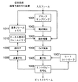
図16において、入力された画像信号に対してまず、ブロックサンプリングユニット1012によってブロックサンプリングが実行される。そして、イントラフレーム符号化においては、サンプルされたブロック画像データは加算器1013の処理が実行されずに、加算器1013を通過してDCT変換ユニット1014に入力される。一方、予測フレーム符号化においては、加算器1013は、サンプルされたブロック画像データから動き検出及び補償ユニット1025から出力される動き検出画像データを減算して、減算結果の画像データをDCT変換ユニット1014に出力する。そして、DCT変換処理がユニット1014で実行された後、量子化処理がユニット1015で実行される。
【0136】
DCT変換領域予測処理はユニット1017で実行され、1018は予測のために前に復号化されたブロックを格納するためのブロックメモリである。加算器1016は、量子化ユニット1015から出力される現時点のDCT変換ブロックから、DCT変換領域予測ユニット1017から出力される復号化された隣接するブロックを減算する。この符号化された隣接するブロックの決定はDCT変換領域予測ユニット1017において行われる。最後に、予測されたDCT変換ブロックに対して、ユニット1020によってエントロピーVLC符号化処理が実行され、符号化されたビットはビットストリームに書きこまれる。
【0137】
加算器1019は、予測のために用いられる前の隣接するブロックを、予測ブロックに加算することにより、現時点のDCT変換ブロックを復元する。次いで、復元されたDCT変換ブロックに対して、逆量子化処理及び逆DCT変換処理はそれぞれユニット1021及び1022において実行される。局所的に復号化されて逆DCT変換ユニット1022から出力されるブロックの画像データは加算器1023に入力される。加算器1023は、復元されたブロックの画像データに前のフレームの画像データを加算することによって、再構築された画像データを得てフレームメモリ1024に記憶される。動き検出及び補償処理はユニット1025で実行される。動き検出及び補償処理のための前のフレームを格納するためにフレームメモリ1024が用いられる。
【0138】
<第6の実施形態>
図17は、本発明に係る第6の実施形態である画像予測符号化装置の構成を示すブロック図である。図17の画像予測符号化装置は、量子化処理の前に、DCT変換領域予測処理が実行されたことを特徴としている。入力された画像信号に対して、ユニット1026においてブロックサンプリング処理が実行される。次いで、加算器1027は予測フレーム符号化のために減算を行い、減算結果の画像データは、DCT変換ユニット1028、加算器1029及び量子化ユニット1030を介して、エントロピーVLC符号化ユニット1034及び逆量子化ユニット1033に出力される。
【0139】
ブロックメモリ1032は、ユニット1031のDCT変換領域予測処理のために前のブロックの画像データを格納している。DCT変換ユニット1028から出力される現時点のDCT変換ブロックの画像データは、加算器1029によって、最小ビット使用規則に従ってDCT変換領域予測ユニット1031で選択された前のDCT変換ブロックから減算される。減算結果のDCT変換ブロックの画像データは、量子化ユニット1030によって量子化された後、逆量子化ユニット1033及びエントロピーVLC符号化ユニット1034に出力される。逆量子化ユニット1033は、入力される量子化されたDCT変換ブロックの画像データを逆量子化することにより復元して加算器1035に出力する。加算器1035は、復元されたDCT変換ブロックの画像データを、DCT変換領域予測ユニット1031からの前のDCT変換ブロックの画像データを加算して、加算結果の前のブロックの画像データをブロックメモリ1032に格納するとともに、逆DCT変換ユニット1036に出力する。
【0140】
逆DCT変換ユニット1036は、加算器1035から入力される前のブロックの画像データに対して逆DCT変換処理を実行して、変換処理後の復元された画像データを加算器1037に出力する。加算器1037は、逆DCT変換ユニット1036から出力される復元された画像データに動き検出及び補償ユニット1025から出力される前のフレームの画像データを加算して、加算結果の画像データをフレームメモリ1038に一時的に記憶した後、動き検出及び補償ユニット1025に出力される。
【0141】
<B1.モード決定の一般的な説明>
図18は、図16及び図17のDCT変換領域予測回路1017,1031の構成を示すブロック図である。
【0142】
図18において、1040は予測のために前の隣接するブロックの画像データを格納するブロックメモリである。処理対象の現時点のカレントブロックはユニット1041に入力され、ユニット1041は、ブロックメモリ1040で格納されている前の隣接するDCT変換ブロックから入力されたカレントブロックの画像データを減算して、次の4種類の予測DCT変換ブロックの画像データが得られる。
(a)1042で示されるNo−Predブロック、
(b)1043で示されるUp−Predブロック、
(c)1044で示されるLeft−Predブロック、
(d)1045で示されるOther−Predブロック。
【0143】
ここで、2ビットを用いて上記4つの種類のブロックを示す。すなわち、例えば“00”はNo−Predブロックを示し、“01”はUp−Predブロックを示し、“10”はLeft−Predを示し、“11”はOther−Predブロックを示す。
【0144】
No−Predブロックは、予測無しのときの、現時点のDCT変換ブロックの画像データ自身である。Up−Predブロックは、予測に用いられたブロックが上方に隣接するDCT変換ブロックB2である場合に得られた予測ブロックの画像データを示す。Left−Predブロックは予測に用いられたブロックが左側に隣接するDCT変換ブロックB4である場合に得られた予測ブロックの画像データを示す。Other−Predブロックは予測がDC係数に対してのみ行われたときの予測ブロックの画像データを示す。Other−Predの場合において、2種類の予測方法が存在する。すなわち、Up−DC−Pred(1046)は上方に隣接するDCT変換ブロックB2に基づいてDC係数のみに対して予測が行われた場合に得られた予測ブロックの画像データを示す。Left−DC−Pred(1047)は左側に隣接するDCT変換ブロックB4に基づいてDC係数のみに対して予測が行われた場合に得られた予測ブロックの画像データを示す。この2つのケースに対して、もう1つビットが指示のために必要となる。例えば“0”はUp−DC−Pred(1046)を示し、“1”はLeft−DC−Pred(1047)を示すように使用される。
【0145】
斜め方向に隣接するブロックB1、B3に基づいた予測は可能ではあるがその予測結果は上方や左側のブロックに予測によるもののようによくないので、本実施形態では用いていない。
【0146】
全ての予測されたブロックに対して、ユニット1048によって実際のエントロピー符号化処理が実行されることにより検査され、チェックされる。異なる予測されたブロックに使用されたビットはユニット1049において比較される。最後に、ユニット1050は最小ビット使用規則に基づいて予測されたDCT変換ブロックを決定し、指示ビットとともに予測されたDCT変換ブロックを出力する。すなわち、ビット数が最小の予測されたDCT変換ブロックを選択する。
【0147】
<B2.モード決定の実施>
図19は、図18のDCT変換領域予測回路におけるDC/AC予測の符号化方法の一例を示す画像の模式図である。
【0148】
図19において、先に定義されたDC/AC予測された画像データの部分集合が実際の使用に対して図示されている。カレントブロック1101はカレントマクロブロックの上部左側の8×8ブロックであり、カレントブロック1102はカレントマクロブロックの上部右側の8×8ブロックである。A及びBは、カレントブロック1101に隣接する8×8ブロックである。カレントブロック1101の強調された上部行及び左列はそれぞれ、隣接ブロックであるA及びBの同一場所から予測される。つまり、カレントブロック1101の最上行はその上のブロックAの最上行から予測され、カレントブロック1101の左列はその左のブロックBの左列から予測される。同様の手順で、カレントブロック1102はその上のブロックD及びその左のカレントブロック1から予測される。
【0149】
C(u,v)を符号化すべきブロックとし、Ei(u,v)をモードiの場合の予測誤差であって、A(u,v)及び/又はB(u,v)の各ブロックから予測値を減算して求めたものであるとする。実際の実施においては、節B1において前述した最も頻度が多い次の3つのモードのみが使用される。
【0150】
(a)モード0:DC予測のみ
【0151】
【数1】
E0(0,0)=C(0,0)−(A(0,0)+B(0,0))/2,
E0(u,v)=C(u,v),
u≠0;v≠0;u=0,…,7;v=0,…,7
【0152】
(b)モード1:上側ブロックからのDC/AC予測
【0153】
【数2】
E1(0,v)=C(0,v)−A(0,v),v=0,…,7,
E1(u,v)=C(u,v),
u=1,…,7;v=0,…,7
【0154】
(c)モード2:左側ブロックからのDC/AC予測
【数3】
E2(u,0)=C(u,0)−B(u,0),u=0,…,7,
E2(u,v)=C(u,v),
u=0,…,7;v=1,…,7.
【0155】
モードの選択は、マクロブロックにおける4つの輝度信号のブロックに対して予測された誤差の絶対値の和、SADmodeiを計算して、そのうちの最小値を有するモードを選択することにより行われる。
【0156】
【数4】
モードの決定は、異なる符号化ビットレートを目標とするアプリケーションの違いに依存して、ブロックベース及びマクロブロックベースの両方で実行することができる。モードは、次の表1の可変長コードを使用して符号化される。
【0158】
【表1】
量子化後にDC/AC予測を実行する場合、先行する水平方向の隣接ブロック又は垂直方向の隣接ブロックでは通常、使用する量子化のステップが異なるため、DC/AC予測を正確に行うためには、量子化されたDCT変換係数をスケーリングするために幾つかの種類の重み係数が必要とされる。
【0160】
QacAをブロックA(図19参照。)の量子化されたDCT変換係数とし、QacBをブロックB(図19参照。)の量子化されたDCT変換係数とする。QstepAをブロックAの量子化に使用される量子化ステップとすると、QstepBはブロックAの量子化に使用する量子化ステップであり、QstepCはカレントブロックCの量子化に使用すべき量子化ステップであり、従ってスケーリング方程式は以下の通りである。
【0161】
【数5】
Q’acA=(QacA×QstepA)/QstepC
【数6】
Q’acB=(QacB×QstepB)/QstepC
【0162】
ここで、Q’acAはブロックAからのDCT変換係数であり、カレントブロックCの最上行の予測に使用される。また、Q’acBはブロックBからのDCT変換係数であり、カレントブロックCの左列の予測に使用される。
【0163】
<第7の実施形態>
図20は、本発明に係る第7の実施形態である画像予測復号化装置の構成を示すブロック図である。
【0164】
図20において、画像予測符号化装置からのビットストリームは、エントロピーVLD復号化ユニット1051に入力され、可変長復号化される。復号化された画像データは、加算器1052によって、DCT変換領域予測ユニット1053からの前の隣接するDCT変換ブロックの画像データと加算することにより、DCT変換ブロックの画像データが復元される。前に隣接するDCT変換ブロックは、どのブロックであるかは、ビットストリームからとり出された指示ビットによって知らされ、ユニット1053において予測のために使用される。1054は、予測のために用いる隣接するDCT変換ブロックを格納するためのブロックメモリである。加算器1052から得られる復元されたDCT変換ブロックは逆DCT変換ユニット1055に出力される。逆DCT変換ユニット1055は入力されたDCT変換ブロックに対して逆DCT変換処理を実行することにより復元されたDCT変換係数の画像データを生成して、加算器1056に出力する。加算器1056は、逆DCT変換ユニット1055からの復元された画像データを、動き検出及び補償ユニット1057からの前のフレームの画像データと加算することにより、動き検出及び補償されかつ復号化された画像データを生成して出力する。当該復号化された画像データは、動き検出及び補償のために前のフレームの画像データを格納するフレームメモリに一時的に格納した後、動き検出及び補償ユニット1057に出力される。動き検出及び補償ユニット1057は、入力される画像データに対して、動き検出及び補償処理が実行される。
【0165】
さらに、加算器1056から出力される復号化された画像データは、図16及び図17のブロックサンプリングユニット1012,1026の処理に対応する逆の復元処理により、元の画像データが復元される。
【0166】
さらに、1059は逆量子化ユニットであり、図17に示すように量子化処理の前にDCT変換領域予測処理が行われる場合は、当該逆量子化ユニット1059は図20における1059aの位置に挿入される一方、図16に示すように量子化処理の後にDCT変換領域予測処理が行われる場合は、当該逆量子化ユニット1059は図20における1059bの位置に挿入される。
【0167】
図21は、図20の画像予測復号化装置におけるDC/AC予測の復号化方法を示すフローチャートである。すなわち、図21では、DC/AC予測モードを取得し、隣接するDC/AC予測値からDCT変換係数を再構成するためのビットストリームの復号化の詳細が図示されている。
【0168】
まず、ステップ1059において、入力されるビットストリームから指示ビットを復号化し、ステップ1060で、指示ビットのフラグがチェックされ、それが「0」であれば、ステップ1061で上側ブロック及び左側ブロックの画像データの平均値からDC値を計算してステップ1063に進む。ステップ1060でNOであればステップ1062に進み、ステップ1062でチェックされた指示フラグが「10」であれば、ステップ1063で左側ブロックの左列の画像データが抽出され、ステップ1065に進む。ステップ1062でNOであればステップ1064に進み、ステップ1064でチェックされた表示フラグが「11」であれば、ステップ1065で上側ブロックの最上行の画像データが抽出され、ステップ1066に進む。最後に、ステップ1066では、ステップ1061、1063、又は1065で取得又は抽出されたDCT変換係数がカレントブロックの対応するDCT変換係数に加算される。
【0169】
さらに、以下、本実施形態グループの変形例について説明する。
【0170】
(a)上記ブロックサンプリングユニット1012,1026は、4つのブロックのグループの中の二次元配列の画素は、第1のブロックでは奇数番目の行にある奇数番目の画素から成り、第2のブロックでは奇数番目の行にある偶数番目の画素から成り、第3ブロックでは偶数番目の行にある奇数場番目の画素から成り、第4ブロックでは偶数番目の行にある偶数番目の画素から成るように、画素を交互に差し挟むインターリーブ処理を含んでもよい。
(b)上記予測ブロックは、上記ブロックメモリに格納され、前に復元されたブロックであって、符号化されたカレントブロックに隣接するように位置されたブロックから選択され、ブロック中の全ての変換係数が選択されてもよい。
(c)上記予測ブロックは、上記ブロックメモリに格納され、前に復元されたブロックであって、符号化されたカレントブロックに隣接するように位置されたブロックから選択され、あらかじめ定められたサブセットがブロックの変換係数として選択されてもよい。
【0171】
(d)上記予測ブロックは、上記ブロックメモリに格納され、前に復元されたブロックであって、符号化されたカレントブロックの上方及び左側に隣接するよう位置されたブロックから選択され、当該ブロックの最上行、及び当該ブロックの最左列の変換係数のみが使用され、残りの変換係数はゼロにセットされてもよい。
(e)上記予測ブロックは、上記ブロックメモリに格納され、前に復元されたブロックであって、符号化されたカレントブロックの近傍に位置されたブロックから選択され、各ブロックの変換係数は異なる重み付け関数で重み付けされてもよい。
(f)上記予測ブロックは、上記ブロックメモリに格納され、前に復元されたブロックであって、符号化されたカレントブロックの近傍に位置されたブロックから選択され、各ブロックの変換係数に対して変換演算が実行されてもよい。
【0172】
(g)上記予測ブロックは、上記ブロックメモリに格納され、前に復元されたブロックであって、符号化されたカレントブロックの近傍に位置された複数のブロックの重み付け平均化されてもよい。
(h)復号化された画像データに基づいて、インターリーブされた4個のブロックからなる複数のグループから二次元配列の画素を形成して元の画像データを復元するときに、奇数番目の行にある奇数番目の画素は全て第1のブロックから求め、奇数番目の行にある偶数番目の画素は第2のブロックから求め、偶数番目の行にある奇数番目の画素は第3ブロックから求め、偶数番目の行にある偶数番目の画素は第4ブロックから求めるように、上記復号化された画像データに対して逆インターリーブ処理を実行してもよい。
【0173】
以上説明したように、本発明に係る本実施形態グループによれば、隣接するブロック間におけるDCT変換領域の冗長性を除去又は減少するために大いに効果があり、その結果、使用ビット数を減少させ、最終的に符号化効率を大いに改善することができる。詳細な画像予測符号化装置の例として図18を参照すると、予測処理は、好ましくは、上側又は左側の隣接するブロックを使用することによってのみ実行される。
【0174】
QCIFを含むシーケンスに対しては、上位ビットレート符号化に対して6.4%のビットを節約することができ、下位ビットレート符号化に対して20%のビットを節約することができる。また、例えば、アキヨ(Akiyo)、マザー(Mother)、及びドウター(Daughter)などのテストシーケンスなどの他のQCIFシーケンスに対して、約10%のビットを節約することができる。さらにCIF及びCCIRのシーケンスに対しては、より多くのビット節約が可能である。
【0175】
以上説明したように本発明に係る第2の実施形態グループによれば、現時点の符号化効率を増大させる新しい画像予測符号化装置及び画像予測復号化装置を提供することができる。当該装置では、符号化効率を上げるためには複雑な手段は必要とせず、その回路構成は、非常に簡単で容易に形成できる。
【0176】
<第3の実施形態グループ>
第3の実施形態グループは、第8の実施形態を含む。
【0177】
本発明者は、従来技術の問題点に鑑みて、画像符号化効率は、2つの画像間又は1つの画像内のブロックの内部における冗長性ばかりでなく、画像内のブロック間の冗長性を削減するとともに、ブロックのスキャンパターンを適切にすることによりさらに冗長性を改善することを考えた。
【0178】
同じ位置にあっても隣接するブロックの中のDCT変換係数は多くの場合非常によく似ていることが見出されている。この2つのブロックに対する原画像の特質が非常によく似ている場合、もしくは水平又は垂直ライン、対角線その他の画像パターンが同じものを含んでいる場合、上記のことは正しいといえる。情報理論の観点から同じ情報は冗長性を意味することになる。
【0179】
ブロックを越えてDCT変換領域の中に存在する冗長性は、以前のブロックの適応性予測により除去されるか又は削減されることができる。このことはVLCエントロピー符号化は予測誤差信号のより小さいエントロピーのためのより高い符号化効率を達成できるという結果になる。
【0180】
同時に、水平及び垂直の構造は、最左側の列及び最上行の変換ブロックに、重要なDCT変換係数が集中するという結果になることは公知である。従って、本発明に係る実施形態は、予測モードに基づいて、スキャンを適応化することにより係数のスキャンにおける上述の問題点を解決することができる。
【0181】
本発明に係る実施形態は、他のブロックからカレントブロックのDCT変換係数を適応的に予測し、その結果隣接するブロック間の冗長性を除去する方法を提供する。予測誤差の情報は量子化DCT変換係数のエントロピーをより小さくする予測モードにスキャン方法を適応化することによりさらに縮少される。その結果、DCT変換係数を符号化するためのビットの数を削減できる。
【0182】
この問題点を解決するために、予測モードの決定を実行する方法が各予測及びスキャン方法により発生される実際のビットレートに基づいて得られる。
【0183】
本発明に係る実施形態は、現在のカレントブロックのDCT変換係数を予測する方法を提供するものである。DCT変換は同じ値、又は同じDCT変換係数の分布を同じブロックの画像データに与える傾向があるので、カレントブロックは通常他の隣接するブロックの中のDCT変換係数と良好な相互関係を保持している。
【0184】
入力された画像データは、イントラフレームであるか又は一時的に予測されたフレームであるかのいずれかであり、まず、入力された画像データに対して、通常ブロックを基礎とするDCT変換処理が実行される。カレントブロックのDCT変換係数が得られた後に、DCT変換領域の予測は量子化の前、又は後に実行することができる。
【0185】
カレントブロックの中のDCT変換係数は上方の左側に対角線方向(斜め方向)に位置した以前の隣接するブロックから予測することができる。それらは、図23に示すように、その時刻において既に復号化されている。予測されたブロックは、カレントブロックにおける同じ位置のDCT係数から前の隣接するブロックの1つ又はそれ以上のDCT係数を減算することによって、予測された誤差信号を発生する。
【0186】
異なる予測モードからの予測誤差信号が、予測が量子化処理の前になされるならば量子化される。量子化された予測誤差信号は、エントロピー符号化が実行される前にシーケンスの(一連の)画像データに対してスキャンされる。最小ビット使用規則に基づいて予測されたブロック、すなわち最小のビットを有する予測ブロックが選択される。このブロックの符号化データは使用する予測モードとともに画像予測復号化装置に送られる。
【0187】
画像予測復号化装置は、使用した予測モード及びブロックの符号化されたデータを用いて、予測されたブロックを復号化する。ブロックに対する符号化されたデータに対する逆のエントロピー復号化の後に、量子化された予測誤差は用いられるスキャンモードに従って逆にスキャンされる。もし量子化処理が予測処理の後の実行されるならば、ブロックは逆量子化されることになる。再構築されたブロックは、予測モードによって指示された、前に復号化された隣接するブロックの中のDCT変換係数を現在のDCT変換係数に加算することにより得ることができる。一方、量子化処理が予測処理の前に実行されるならば、再構築された係数は逆量子化される。最後に、逆DCT変換処理が各ブロックに対して再構築されたDCT変換係数に適用され、復号化された画像を得ることができる。
【0188】
本発明に係る実施形態は、隣接するブロックを越えてDCT変換領域の中に存在する冗長性を減少させる画像予測符号化装置及び画像予測復号化装置を提供するものである。
【0189】
<第8の実施形態>
図24は、本発明に係る第8の実施形態である画像予測符号化装置の構成を示すブロック図である。図24の画像予測符号化装置は、図22の従来技術の画像予測符号化装置と比較して、
(a)加算器2035、
(b)H/V/Zスキャンユニット2036、
(c)加算器2038、
(d)ブロックメモリ2039、及び
(e)量子化スケーリングを有するDCT変換領域予測ユニット2040を備えたことを特徴としている。
【0190】
イントラフレーム符号化(フレーム内符号化)においては、入力された画像信号に対して、ユニット2031でブロックサンプリング処理が実行された後に、直接にユニット2033でDCT変換処理が実行される。次いで、ユニット2034で、DCT変換ユニット2033から出力されるDCT変換係数に対して量子化処理が実行される。一方、インターフレーム符号化又はフレーム間符号化(予測フレーム符号化)においては、ユニット2031のブロックサンプリング処理の後に、加算器2032は、ブロックサンプリング処理後の画像データから、動き検出及び補償ユニット2045から出力された画像データを減算して、予測誤差データを得る。次いで、この予測誤差データは、DCT変換処理を実行するDCT変換ユニット2033及び量子化処理を実行する量子化ユニット2034を介して加算器2035に出力される。DCT変換係数は、ユニット2040のDCT変換領域処理によって予測され、予測されたDCT変換係数は加算器2035に入力される。加算器2035は、量子化ユニット2034からのDCT変換係数から、DCT変換領域予測ユニット2040からの予測されたDCT変換係数を減算して、減算結果の予測誤差のDCT変換係数を、H/V/Zスキャンユニット2036及び加算器2038に出力する。H/V/Zスキャンユニット2036は、選択された予測モードに依存して、入力されたDCT変換係数に対して適応的に、水平スキャン、垂直スキャン又はジグザグスキャンを実行して、スキャン処理後のDCT変換係数をエントロピーVLC符号化ユニット2037に出力する。次いで、エントロピーVLC符号化ユニット2037は、入力されたDCT変換係数をエントロピーVLC符号化処理を実行して、符号化されたビットストリームを受信側又は再生側の画像予測復号化装置に伝送する。
【0191】
加算器2038は、加算器2035から出力される量子化されたDCT変換係数と、DCT変換領域予測ユニット2040からの予測されたDCT変換係数とを加算することにより、復元された量子化DCT変換係数データを得る。当該量子化DCT変換係数データは、ブロックメモリ2039及び逆量子化ユニット2041に出力される。
【0192】
当該画像予測符号化装置に設けられるローカルデコーダにおいて、加算器2038からの復元されたDCT変換係数データは、次の予測を行うために1つのブロックのデータを格納するブロックメモリ2039に一時的に記憶された後、DCT変換領域予測ユニット2040に出力される。逆量子化ユニット2041は、入力される量子化DCT変換係数を逆量子化して逆DCT変換ユニット2042に出力し、次いで、逆DCT変換ユニット2042は、入力される復元されたDCT変換係数を逆DCT変換処理を実行して、現時点のブロックの画像データを復元して加算器2043に出力する。
【0193】
フレーム間符号化においては、ローカル復号化された画像データを生成するために、加算器2043は、動き検出及び補償ユニット2045によって動き検出及び補償された画像データと、逆DCT変換ユニット2042からの復元された画像データとを加算して、ローカル復号化された画像データを得て、ローカルデコーダのフレームメモリ2044に記憶される。なお、加算器2043とフレームメモリ2044と動き検出及び補償ユニット2045の構成及び処理は、図22の従来技術のユニット2009、2010及び2011と同様である。
【0194】
最終的には、ビットストリームはエントロピー符号化ユニット2037から出力されて画像予測符号化装置に送られる。
【0195】
図25は、本発明に係る第8の実施形態である画像予測復号化装置の構成を示すブロック図である。図25の画像予測復号化装置は、図23の従来技術の画像予測復号化装置に比較して、
(a)H/V/Zスキャンユニット2052、
(b)加算器2053、
(c)DCT変換領域予測ユニット2055、及び
(d)ブロックメモリ2054、
を備えたことを特徴とする。
【0196】
図25において、画像予測符号化装置からのビットストリームは、可変長デコーダユニット2051において復号化される。復号化されたデータは、H/V/Z逆スキャンユニット2052に入力され、スキャンモードに依存して、水平に逆方向で、垂直に逆方向で、又はジグザグに逆方向でスキャンされる。スキャン処理後のデータは加算器2053に入力され、加算器2053は、逆スキャン処理後のデータと、DCT変換予測ユニット2055からの予測誤差データとを加算することにより、復号化されたDCT変換係数データを得て、これを逆量子化ユニット2056に出力するとともに、ブロックメモリ2054に記憶される。次いで、逆量子化ユニット2056は、入力される符号化されたDCT変換係数データを逆量子化して逆量子化されたDCT変換係数データを得て、逆DCT変換ユニット2057に出力する。逆DCT変換ユニット2057は、入力されるDCT変換係数データに対して逆DCT変換処理を実行して、元の画像データを復元して、加算器2058に出力する。フレーム間符号化においては、加算器2058は、動き検出及び補償ユニット2060からの予測誤差データに、逆DCT変換ユニット2057からの画像データを加算して、局所的に復号化された画像データを得て、外部装置に出力するとともに、フレームメモリ2059に記憶する。
【0197】
さらに、加算器2058から出力される復号化された画像データは、図24のブロックサンプリングユニット2031の処理に対応する逆の復元処理により、元の画像データが復元される。
【0198】
以上の実施形態においては、量子化処理が予測処理に先だって行われる。変形例においては、予測処理の後に量子化処理を行ってもよい。この場合、ローカルデコーダ及び画像予測復号化装置では、予測値が加算される前に逆量子化処理が実行される。他の詳細は全て、上述の実施形態と同様である。
【0199】
図26は、第8の実施形態において、ブロック分割から得られた、フレームのマクロブロックとブロックの構造を示し、かつブロック予測方法を示す画像の模式図である。図26の拡大図は、カレントブロックに対する予測データがどのように符号化されるかを示す。ここで、ブロックC(u,v)は、上側に隣接するブロックA(u,v)と、左方向に隣接するブロックB(u,v)とから得られる。次に、本発明にこの実施形態を更に詳しく説明する。
【0200】
<C1.予測に使用される係数の番号>
予測に使用される係数のナンバーは画像データのシーケンスに依存している。フラグAC_Coeffは、各画像に使用される係数の最適の数を適応的に選択するために使用される。フラグは下の表2に示され、サイド情報の一部として画像予測符号化装置から画像予測復号化装置に送られる。フラグAC_Coeffに対する固定長コード及びFLCを表2に示す。ここで、FLC(Fixed Length Coding;固定長符号化)は、すべての可能なイベントを表すために、固定長のコードワードを割り当てる可逆符号化である。
【0201】
【表2】
ここで、ACnは、用いられるモードに依存して、A(0,n)又はB(n,0)である。
【0203】
この実施形態の特別なケースでは、最上行及び最左列のすべてのAC係数が予測のために使用される。このケースでは、画像予測符号化装置と画像予測復号化装置との両方が、このデフォルト値を同意しているとき、フラグを必要としない。
【0204】
<C2.量子化ステップのスケーリング>
隣接するブロックがカレントブロックからの異なる量子化ステップサイズを用いて量子化されるときは、AC係数の予測はそんなに能率的ではない。従って、当該予測方法は、予測データが、現在のカレントブロックの量子化ステップサイズの比と、予測データのブロックの量子化ステップの比とによってスケーリングされるように変形される。この定義は次の節C3.における方程式を用いて与えられる。
【0205】
<C3.予測モード>
設定される複数のモードは次の通りである。
【0206】
(a)モード0:処理ブロックから上側のブロックからのDC予測(「上のDCモード」と略す。)
【0207】
【数7】
E0(0,0)=C(0,0)−A(0,0),
E0(u,v)=C(u,v)
【0208】
(b)モード1:処理ブロックから左側のブロックからのDC予測(「左のDCモード」と略す。)
【0209】
【数8】
E1(0,0)=C(0,0)−B(0,0),
E1(u,v)=C(u,v)
【0210】
(c)モード2;処理ブロックから上側のブロックからのDC/AC予測(「上のDC/ACモード」と略す。)
【0211】
【数9】
E2(0,0)=C(0,0)−A(0,0),
E2(0,v)=C(0,v)−A(0,v)・QA/QC,
v=1,2,…,AC_Coeff,
E2(u,v)=C(u,v)
【0212】
(d)モード3:処理ブロックから左側のブロックからのDC/AC予測(「左のDC/ACモード」と略す。)
【0213】
【数10】
E3(0,0)=C(0,0)−B(0,0),
E3(u,0)=C(u,0)−B(u,0)・QB/QC
u=1,2,…,AC_Coeff,
E3(u,v)=C(u,v)
【0214】
<C4.適応的水平/垂直/ジグザグスキャン>
上のような4個の予測モードが与えられるならば、フレーム内符号化の効率は係数のスキャンを採用することによりさらに改善させることができる。
【0215】
図27、図28及び図29はそれぞれ、第8の実施形態における係数スキャンに用いられる水平スキャン、垂直スキャン及び水平スキャンの順序を説明するための画像の模式図である。ここで、これらのスキャンは集合的にH/V/Zスキャンとして参照される。
【0216】
<C5.明示的モードの決定>
明示的(explicit)モードの決定においては、予測モードの決定が画像予測符号化装置において実行され、その決定情報が、ビットストリームにおける幾つかの符号化されたビット情報を用いて画像予測符号化装置から画像予測復号化装置に明示的に送られる。
【0217】
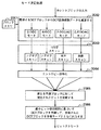
図30は、第8の実施形態に使用されているモード決定処理を示すフローチャートである。
【0218】
図30において、カレントブロックのDCT変換係数データはユニット2062に入力され、ユニット2062は、ブロックメモリ2061からの隣接するブロックのDCT変換係数データから入力されたカレントブロックのDCT変換係数データを減算することにより、DCT変換予測処理が実行される。ユニット2062では、節C3.で説明された4つのモードで、DCT変換予測処理が実行される。次いで、H/V/Zスキャンユニット2063では、係数のスキャン処理が実行され、ここでは、図30に示すように、節C4.で説明したそれぞれ対応するスキャン処理が実行される。さらに、スキャン処理後のDCT変換係数データは、エントロピー符号化ユニット2064に送られ、ここで可変長符号化処理が実行される。次いで、ユニット2065では、異なるモードで発生されたすべてのビットが比較されて、ユニット2066では、最少のビットを発生する予測モードのDCT変換係数のブロックが選択される。これらのDCT変換係数データのビットは予測モードの値とともにユニット2066からビットストリームとして画像予測復号化装置に送られる。なお、予測モードは、次の表3の固定長コードを用いて符号化される。
【0219】
【表3】
<C6.暗黙的モードの決定>
モード決定の第2の実施例では、画像予測符号化装置と画像予測復号化装置とが同一の予測モード決定機能を共有している。画像予測符号化装置と画像予測復号化装置は共に、カレントブロックに隣接する復号化されたブロックのDC係数値に基づいて、予測モードの決定に関する方向性を決定する。すなわち、暗黙的(implicit)モードの決定においては、暗黙的モードの決定が幾つかの規則を用いて画像予測符号化装置と画像予測復号化装置において実行される。そして、モード決定を示す付加的な情報データは画像予測符号化装置から画像予測復号化装置に対して送られない。
【0221】
図31は、第8の実施形態の暗黙モード決定におけるブロックの関係を示す画像の模式図である。すなわち、図31は、各ブロックと予測対象であるカレントブロックとの位置関係を示している。
【0222】
図31において、ブロックCは現在予測中の処理対象のカレントブロックである。ブロックAは、予測中のカレントブロックCの上側のブロックである。ブロックCは、カレントブロックCから左側に位置するブロックである。ブロックC’は、カレントブロックCとは対角位置にあるブロックAとブロックBの間のブロックである。
【0223】
まず、DCの方向が決定される。個別の決定方法を使用して、AC係数も同様に予測中であるか否かが決定される。これを行うには、予測係数の絶対値の差の合計を非予測係数の絶対値と比較し、何れが小さいかを判断する。画像予測復号化装置へのこの指示には、1ビットが使用される。DC予測の方向性、及びAC係数が予測されているか否かの決定には、以下の式が使用される。表3は、可能性のある4つの結論を要約したものである。
【0224】
(A1)もし
【数11】
(B(0,0)−C’(0,0)<C’(0,0)−A(0,0))
のとき、
【数12】
E(0,0)=C(0,0)−A(0,0)
であり、
(a1)もし
【0225】
【数13】
のとき、
【0227】
【数14】
E(0,v)
=C(0,v)−A(0,v)・QA/QC,v=1,…,7,
【0228】
(a2)上記数13が成立しなければ、
【数15】
E(0,v)=C(0,v)
である。
【0229】
(A2)上記数11が成立しなければ、
【数16】
E(0,0)=C(0,0)−B(0,0)
であり、
(b1)もし
【0230】
【数17】
のとき、
【0232】
【数18】
E(u,0)
=C(u,0)−B(u,0)・QB/QC,v=1,…,7,
【0233】
(b2)上記数17が成立しなければ、
【数19】
E(u,0)=C(u,0)
である。
【0234】
さらに、他の全ての係数に対して、
【数20】
E(u,v)=C(u,v)
である。
【0235】
【表4】
以上の第8の実施形態において、DCT変換係数予測処理はユニット2040によって、量子化された変換係数データについて行っているが、本発明はこれに限らず、図17の第6の実施形態と同様に、量子化されない変換係数データについて行ってもよい。この場合、対応する画像予測復号化装置においては、図25において、逆量子化ユニット2056は、逆スキャンユニット2052と、加算器2053に移動されて挿入される。
【0237】
以下、第8の実施形態の変形例について述べる。
【0238】
(a)ブロックサンプリングユニット2031は、4つのブロックのグループの中の二次元配列の画素は、第1のブロックでは奇数番目の行にある奇数番目の画素から成り、第2のブロックでは奇数番目の行にある偶数番目の画素から成り、第3ブロックでは偶数番目の行にある奇数場番目の画素から成り、第4ブロックでは偶数番目の行にある偶数番目の画素から成るように、画素を交互に差し挟むインターリーブ処理を含んでもよい。
(b)上記予測ブロックは、上記ブロックメモリに格納され、前に復元されたブロックであって、符号化されたカレントブロックに隣接するように位置されたブロックから選択され、ブロック中の全ての係数データが選択されてもよい。
(c)上記予測ブロックは、上記ブロックメモリに格納され、前に復元されたブロックであって、符号化されたカレントブロックに隣接するように位置されたブロックから選択され、あらかじめ定められたサブセットがブロックの係数データとして選択されてもよい。
【0239】
(d)上記予測ブロックは、上記ブロックメモリに格納され、前に復元されたブロックであって、符号化されたカレントブロックの上方及び左側に隣接するよう位置されたブロックから選択され、当該ブロックの最上行、及び当該ブロックの最左列の係数データのみが使用され、残りの係数データはゼロにセットされてもよい。
(e)上記予測ブロックは、上記ブロックメモリに格納され、前に復元されたブロックから上述の基準に従って選択され、
当該ブロックの最上行又は最左列からの1つ又はそれ以上の係数データを含むサブセットのみを使用することを、画像予測符号化装置と画像予測復号化装置とが通信を行うことにより決定してもよい。
(f)上記予測ブロックは、上記ブロックメモリに格納され、前に復元されたブロックから上述の基準に従って選択され、
当該ブロックの最上行又は最左列からの1つ又はそれ以上の係数データを含むサブセットのみを使用することを、画像予測符号化装置が決定して、決定されたサブセット及び係数データの数を示すフラグを、画像予測復号化装置に送信されるデータに周期的に挿入することにより、画像予測復号化装置に通知してもよい。
【0240】
(g)上記予測ブロックは、上記ブロックメモリに格納され、前に復元されたブロックから上述の基準に従って選択され、
各ブロックの係数データは、符号化されるカレントブロックの量子化ステップサイズと予測ブロックの量子化ステップサイズの比に等しい比で乗算されてもよい。
(h)上記予測ブロックは、上記ブロックメモリに格納され、前に復元されたブロックから上述の基準に従って選択され、
各ブロックの係数データは、異なる重み付け関数で重み付けされてもよい。
(i)上記予測ブロックは、上記ブロックメモリに格納され、前に復元されたブロックから上述の基準に従って選択され、
各ブロックの係数データに対して所定の変換演算が実行されてもよい。(j)上記予測ブロックは、符号化されるカレントブロックに隣接して位置する、上記ブロックメモリに格納され、前に復元されたブロックの重み付け平均値として得てもよい。
【0241】
(k)スキャン方法は、
(i)係数データが、左から右に向かって、行毎に、最上行で始まり、最下行で終わるようにスキャンされる水平スキャンと、
(ii)係数データが、最上行から最下行に向かって、列毎に、最左列から始まり、最右列で終るようにスキャンされる垂直スキャンと、
(iii)係数データが、最上行の最左の係数データから最下行の最右の係数データに向かって、対角線方向にスキャンされるジグザグスキャンとのうちの少なくとも1つのスキャン方法を含んでもよい。
【0242】
(l)上記予測ブロックは、上記ブロックメモリに格納され、前に復元されたブロックから上述の基準に従って選択され、
上記予測ブロックの予測モードは、
(i)処理対象のカレントブロックから上側に位置するブロックからの、DC係数として呼ばれる当該ブロックの平均値を表す最上及び最左の係数データのみを予測のために使用する第1のモードと、
(ii)処理対象のカレントブロックから左側に位置するブロックからの、DC係数のみを予測のために使用する第2のモードと、
(iii)処理対象のカレントブロックから上側に位置するブロックの最上行からの、DC係数及び、高周波成分を含む0個又はそれ以上のAC係数を予測のために使用する第3のモードと、
(iv)処理対象のカレントブロックから左側に位置するブロックの最左列からの、DC係数及び、高周波成分を含む0個又はそれ以上のAC係数を予測のために使用する第4のモードと、
の少なくとも1つの予測モードを含み、
上記予測誤差の係数データはジグザグスキャンのスキャン方法でスキャンされてもよい。
【0243】
(m)上記予測ブロックは、上記ブロックメモリに格納され、前に復元されたブロックから上述の基準に従って選択され、
上記予測誤差の係数データは、上述のスキャン方法の1つに従ってスキャンされ、
上記予測誤差の係数データを予測する予測モードは、
(i)処理対象のカレントブロックから上側に位置するブロックにおけるDC係数のみが予測のために使用され、上記予測誤差の係数データに対して、ジグザグスキャンでスキャン処理が実行される第1のモードと、
(ii)処理対象のカレントブロックから左側に位置するブロックにおけるDC係数のみが予測のために使用され、上記予測誤差の係数データに対して、ジグザグスキャンでスキャン処理が実行される第2のモードと、
(iii)処理対象のカレントブロックから上側に位置するブロックの最上行におけるDC係数及び、高周波成分を含む0個又はそれ以上のAC係数が予測のために使用され、上記予測誤差の係数データに対して、水平スキャンでスキャン処理が実行される第3のモードと、
(iv)処理対象のカレントブロックから左側に位置するブロックの最左列におけるDC係数及び、高周波成分を含む0個又はそれ以上のAC係数が予測のために使用され、上記予測誤差の係数データに対して、垂直スキャンでスキャン処理が実行される第4のモードと、
の少なくとも1つを含んでもよい。
【0244】
(n)上記復号化された画像データに基づいて、インターリーブされた4個のブロックからなる複数のグループから二次元配列の画素を形成して元の画像データを復元するときに、奇数番目の行にある奇数番目の画素は全て第1のブロックから求め、奇数番目の行にある偶数番目の画素は第2のブロックから求め、偶数番目の行にある奇数番目の画素は第3ブロックから求め、偶数番目の行にある偶数番目の画素は第4ブロックから求めるように、上記復号化された画像データに対して逆インターリーブ処理を実行してもよい。
(o)画像予測符号化装置と画像予測復号化装置は、予め決められた同一のルールを用いて、上記予測モードを決定してもよい。
(p)画像予測符号化装置と画像予測復号化装置は、予め決められた同一のルールを用いて、上記スキャン方法を決定してもよい。
【0245】
以上説明したように、本発明に係る第3の実施形態グループによれば、隣接するブロックを越えてDCT変換領域の中の冗長性を削減又は除去するのに非常に効果的であり、使用ビットのビット数を削減し、その結果、符号化の効率を大幅に改善することができる。これは新しいビデオ圧縮アルゴリズムにおけるツールとしても有用である。
【0246】
以上の実施形態において、画像予測符号化装置及び画像予測復号化装置について述べているが、本発明はこれに限らず、上記画像予測符号化装置における各手段、各ユニットなどの構成要素をそれぞれ各ステップに置き換えたステップを含む画像予測符号化方法であってもよいし、上記画像予測復号化装置における各手段、各ユニットなどの構成要素をそれぞれ各ステップに置き換えたステップを含む画像予測復号化方法であってもよい。この場合、例えば、上記画像予測符号化方法及び/又は上記画像予測復号化方法の各ステップがプログラムとして記憶装置に記憶され、マイクロプロセッサユニット(MPU)、中央演算処理装置(CPU)などのコントローラは当該プログラムを実行することにより、画像予測符号化処理及び/又は上記画像予測復号化処理を実行する。
【0247】
また、本発明は、上記画像予測符号化方法及び/又は上記画像予測復号化方法における各ステップを含むプログラムを記録した記録媒体であってもよい。当該記録媒体は、例えば記録領域がセクタ形状に分割され、又は記録領域が渦巻き形状で各ブロックに分割された円盤形状を有し、例えば、CD−ROM、DVDなどの光ディスク又は光磁気ディスク、もしくは、フロッピーディスクなどの磁気記録ディスクである。
【0248】
【発明の効果】
以上詳述したように、本発明に係る画像予測符号化装置によれば、入力される符号化画像データを互いに隣接する複数の小領域の画像データに分割する分割手段と、
上記分割手段によって分割された互いに隣接する複数の小領域の画像データの中で処理対象の小領域の画像データを符号化するときに、上記処理対象の小領域の画像データに隣接する再生された再生小領域の画像データを上記処理対象の小領域の画面内予測小領域の画像データとし、上記画面内予測小領域の画像データを最適予測小領域の画像データとし、上記処理対象の小領域の画像データと上記最適予測小領域の画像データとの差分である差分小領域の画像データを生成する第1の生成手段と、
上記生成手段によって生成された差分小領域の画像データを符号化する符号化手段と、
上記符号化手段によって符号化された差分小領域の画像データを復号化する復号化手段と、
上記復号化手段によって復号化された差分小領域の画像データを上記最適予測小領域の画像データに加算することにより再生された再生小領域の画像データを生成する第2の生成手段とを備える。
従って、処理対象の小領域の画像データに隣接する再生された画素値を画面内予測信号の画素値とするだけで、従来技術に比較して低い演算量で簡単に高精度な予測信号を生成することができ、フレーム内符号化のビット数を削減することができるという特有の効果が得られる。
また、本発明に係る画像予測符号化装置によれば、入力された画像信号をそれぞれ二次元配列の画素値を含む複数のブロックの画像データにサンプリングするサンプリング手段と、
上記サンプリング手段によってサンプリングされたブロックの画像データを所定の変換領域の係数データに変換する変換手段と、
復元されたブロックの係数データを格納するブロックメモリと、
上記ブロックメモリに格納された前に再構築されたブロックの係数データに基づいて、上記変換手段によって変換されたブロックの係数データに対して複数の予測ブロックの係数データを形成する予測手段と、
上記予測手段によって形成された複数の予測ブロックの係数データのうち、最も効率が良い予測ブロックの係数データを決定し選択して出力し、上記選択された予測ブロックを表す指示子を指示ビットの形式で画像予測復号化装置に送信する決定手段と、
上記決定手段によって選択された予測ブロックの係数データを、現時点のカレントブロックの係数データから減算することにより、減算結果の予測誤差の係数データを出力する第1の加算手段と、
上記第1の加算手段から出力される予測誤差の係数データを量子化する量子化手段と、
上記量子化手段からの予測誤差の係数データをエントロピー符号化して、符号化された予測誤差の係数データを画像予測復号化装置に送信する符号化手段と、
上記量子化手段からの予測誤差の係数データを逆量子化して、復元されたブロックの係数データを出力する逆量子化手段と、
上記決定手段から出力される予測ブロックの係数データを、上記逆量子化手段から出力される予測誤差の係数データに加算することにより、復元されたブロックの係数データを出力するとともに、上記ブロックメモリに格納する第2の加算手段と、
上記第2の加算手段から出力されるブロックの係数データを逆変換することにより、復元されたブロックの画像データを生成する逆変換手段とを備える。
従って、現時点の符号化効率を増大させる新しい画像予測符号化装置及び画像予測復号化装置を提供することができる。当該装置では、符号化効率を上げるためには複雑な手段は必要とせず、その回路構成は、非常に簡単で容易に形成できる。
さらに、本発明に係る画像予測符号化装置によれば、入力された画像信号をそれぞれ二次元配列の画素値を含む複数のブロックの画像データにサンプリングするサンプリング手段と、
上記サンプリング手段によってサンプリングされたブロックの画像データを所定の変換領域の係数データに変換する変換手段と、
復元されたブロックの係数データを格納するブロックメモリと、
上記ブロックメモリに格納された前に再構築されたブロックの係数データに基づいて、上記変換手段によって変換されたブロックの係数データに対して複数の予測ブロックの係数データを形成する予測手段と、
上記予測手段によって形成された複数の予測ブロックの係数データのうち、最も効率が良い予測ブロックの係数データ及びスキャン方法を決定し選択して出力し、上記選択された予測ブロック及びスキャン方法を表す指示子を指示ビットの形式で画像予測復号化装置に送信する決定手段と、
上記決定手段によって選択された予測ブロックの係数データを、現時点のカレントブロックの係数データから減算することにより、減算結果の予測誤差の係数データを出力する第1の加算手段と、
上記第1の加算手段から出力される予測誤差の係数データを量子化する量子化手段と、
上記量子化手段からの予測誤差の係数データに対して上記決定手段によって決定されたスキャン方法でスキャン処理を実行して、スキャン処理後の予測誤差の係数データを出力するスキャン手段と、
上記スキャン手段から出力されるスキャン処理後の予測誤差の係数データをエントロピー符号化して、符号化された予測誤差の係数データを画像予測復号化装置に送信する符号化手段と、
上記量子化手段からの予測誤差の係数データを逆量子化して、復元されたブロックの係数データを出力する逆量子化手段と、
上記決定手段から出力される予測ブロックの係数データを、上記逆量子化手段から出力される予測誤差の係数データに加算することにより、復元されたブロックの係数データを出力するとともに、上記ブロックメモリに格納する第2の加算手段と、
上記第2の加算手段から出力されるブロックの係数データを逆変換することにより、復元されたブロックの画像データを生成する逆変換手段とを備える。
従って、隣接するブロックを越えて変換領域の中の冗長性を削減又は除去するのに非常に効果的であり、使用ビットのビット数を削減し、その結果、符号化の効率を大幅に改善することができる。これは新しいビデオ圧縮アルゴリズムにおけるツールとしても有用である。
【図面の簡単な説明】
【図1】 本発明に係る第1の実施形態である画像予測符号化装置の構成を示すブロック図である。
【図2】 図1の画像予測符号化装置に入力される入力画像を8×8のブロックに分割した場合の模式図である。
【図3】 図1の画像予測符号化装置に入力される入力画像を三角領域に分割した場合の模式図である。
【図4】 図1の画像予測符号化装置に用いられる予測信号発生器の第1の実施例の構成を示すブロック図である。
【図5】 図1の画像予測符号化装置に用いられる予測信号発生器の第2の実施例の構成を示すブロック図である。
【図6】 図1の画像予測符号化装置に用いられる予測信号発生器の第3の実施例の構成を示すブロック図である。
【図7】 図1の画像予測符号化装置に用いられる予測信号発生器の第4の実施例の構成を示すブロック図である。
【図8】 本発明に係る第2の実施形態である画像予測符号化装置の構成を示すブロック図である。
【図9】 図1及び図8の画像予測符号化装置に入力される入力画像であって、有意である画素を有する入力画像の一例を示す模式図である。
【図10】 図1及び図8の画像予測符号化装置に入力される入力画像であって、有意である画素を有する入力画像の一例を示す模式図である。
【図11】 図1及び図8の画像予測符号化装置に入力される入力画像であって、有意でない画素を有する入力画像の一例を示す模式図である。
【図12】 本発明に係る第3の実施形態である画像予測復号化装置の構成を示すブロック図である。
【図13】 本発明に係る第4の実施形態である画像予測復号化装置の構成を示すブロック図である。
【図14】 従来技術の画像予測符号化装置の構成を示すブロック図である。
【図15】 画面内予測のための適応的DCT変換領域を説明するための画像の模式図である。
【図16】 本発明に係る第5の実施形態である画像予測符号化装置の構成を示すブロック図である。
【図17】 本発明に係る第6の実施形態である画像予測符号化装置の構成を示すブロック図である。
【図18】 図16及び図17のDCT変換領域予測回路の構成を示すブロック図である。
【図19】 図18のDCT変換領域予測回路におけるDC/AC予測の符号化方法の一例を示す画像の模式図である。
【図20】 本発明に係る第7の実施形態である画像予測復号化装置の構成を示すブロック図である。
【図21】 図20の画像予測復号化装置におけるDC/AC予測の復号化方法を示すフローチャートである。
【図22】 従来技術の画像予測符号化装置の構成を示すブロック図である。
【図23】 従来技術の画像予測復号化装置の構成を示すブロック図である。
【図24】 本発明に係る第8の実施形態である画像予測符号化装置の構成を示すブロック図である。
【図25】 本発明に係る第8の実施形態である画像予測復号化装置の構成を示すブロック図である。
【図26】 第8の実施形態における、フレームのマクロブロックとブロックの構造を示し、かつブロック予測方法を示す画像の模式図である。
【図27】 第8の実施形態における係数スキャンに用いられる水平スキャンの順序を説明するための画像の模式図である。
【図28】 第8の実施形態における係数スキャンに用いられる垂直スキャンの順序を説明するための画像の模式図である。
【図29】 第8の実施形態における係数スキャンに用いられるジグザグスキャンの順序を説明するための画像の模式図である。
【図30】 第8の実施形態に使用されているモード決定処理を示すフローチャートである。
【図31】 第8の実施形態の暗黙モード決定におけるブロックの関係を示す画像の模式図である。
【符号の説明】
101…入力端子、
102…第1の加算器、
103…符号化器、
104…DCT変換器、
105…量子化器、
106…出力端子、
107…復号化器、
108…逆量子化器、
109…逆DCT変換器、
110…第2の加算器、
111…ラインメモリ、
112…予測信号発生器、
200…ブロック、
300,301…三角形、
401,402…発生器、
403,404…画像データ、
500…加算器、
601,602,603…誤差計算器、
604…比較器、
605…スイッチ、
700…動き検出器、
701…動き補償器、
702…フレームメモリ、
703…最適モード選択器、
800,804…形状曲線、
802,805,810…処理対象の小領域、
808…曲線、
901…入力端子、
902…データ解析器、
903…復号化器、
904…逆量子化器、
905…逆DCT変換器、
906…加算器、
907…出力端子、
908…コントローラ、
909…動き補償器、
910…予測信号発生器、
911…ラインメモリ、
912…フレームメモリ、
913…スイッチ、
922…予測信号発生器、
923…動き補償器、
990…形状復号化器、
1001…ブロックサンプリングユニット、
1002…動き検出ユニット、
1003…補償ユニット、
1004…DCT変換器、
1005…量子化ユニット、
1006…エントロピー符号化ユニット、
1007…レートコントローラ、
1008,1009…ユニット、
1010…ローカル復号化フレームメモリ、
1011…基準フレームメモリ、
1012…ブロックサンプリングユニット、
1013…加算器、
1014…DCT変換ユニット、
1015…量子化ユニット、
1016…加算器、
1017…DCT変換領域予測ユニット、
1018…ブロックメモリ、
1019…加算器、
1020…エントロピーVLC符号化ユニット、
1021…逆量子化ユニット、
1022…逆DCT変換ユニット、
1023…加算器、
1024…フレームメモリ、
1025…動き検出及び補償ユニット、
1026…ブロックサンプリングユニット、
1027…加算器、
1028…DCT変換ユニット、
1029…加算器、
1030…量子化ユニット、
1031…DCT変換領域予測ユニット、
1032…ブロックメモリ、
1033…逆量子化ユニット、
1034…エントロピーVLC符号化ユニット、
1035…加算器、
1036…逆DCT変換ユニット、
1037…加算器、
1038…フレームメモリ、
1040…ブロックメモリ、
1041…ユニット、
1042…No−Predブロック、
1043…Up−Predブロック、
1044…Left−Predブロック、
1045…Other−Predブロック、
1048,1049,1050…ユニット、
1051…エントロピーVLD復号化ユニット、
1052…加算器、
1053…DCT変換領域予測ユニット、
1054…ブロックメモリ、
1055…逆DCT変換ユニット、
1056…加算器、
1057…動き検出及び補償ユニット、
1059…逆量子化ユニット、
1101,1102…カレントブロック、
2031…ブロックサンプリングユニット、
2032…加算器、
2033…DCT変換ユニット、
2034…量子化ユニット、
2035…加算器、
2036…H/V/Zスキャンユニット、
2037…エントロピーVLC符号化ユニット、
2038…加算器、
2039…ブロックメモリ、
2040…DCT変換領域予測ユニット、
2041…逆量子化ユニット、
2042…逆DCT変換ユニット、
2043…加算器、
2044…フレーメモリ、
2045…動き検出及び補償ユニット、
2051…可変長デコーダユニット、
2052…H/V/Zスキャンユニット、
2053…加算器、
2054…ブロックメモリ、
2055…DCT変換領域予測ユニット、
2056…逆量子化ユニット、
2057…逆DCT変換ユニット、
2058…加算器、
2059…フレームメモリ、
2060…動き検出及び補償ユニット、
2061…ブロックメモリ、
2062…減算ユニット、
2063…H/V/Zスキャンユニット、
2064…エントロピー符号化ユニット、
2065…比較ユニット、
2066…選択ユニット、
B0…カレントブロック、
B1…左上のブロック、
B2…上のブロック、
B3…右上のブロック、
B4…左のブロック。[0001]
BACKGROUND OF THE INVENTION
The present invention relates to an image predictive coding apparatus and method, an image predictive decoding apparatus and method, and a recording medium. In particular, an image predictive encoding apparatus and method, and an image predictive decoding apparatus and method for storing digital image data of an image that is a still image or a moving image in a recording medium such as an optical disc or transmitting a communication line About. The present invention also relates to a recording medium on which a program including steps of the image predictive encoding method is recorded, and a recording medium on which a program including steps of the image predictive decoding method is recorded.
[0002]
[Prior art]
In order to efficiently store or transmit digital images, it is necessary to perform compression encoding. In addition to discrete cosine transform (hereinafter referred to as DCT transform) represented by JPEG (Joint Photographic Experts Group) and MPEG (Motion Picture Experts Group) as methods for compressing and coding digital images, subband coding is also possible. And waveform encoding methods such as wavelet encoding and fractal encoding. Also, in order to remove redundant signals between images, inter-image prediction using motion compensation is performed, and the difference signal is waveform-encoded.
[0003]
In the MPEG system, an input image is divided into a plurality of 16 × 16 macroblocks for processing. One macroblock is further divided into 8 × 8 blocks, subjected to 8 × 8 DCT transform processing, and then quantized. This is called intraframe coding.
[0004]
On the other hand, a motion detection method such as block matching detects the predicted macroblock with the smallest error in the target macroblock from other frames adjacent in time, and subtracts the detected predicted macroblock from the target macroblock. Then, a differential macroblock is generated, subjected to 8 × 8 DCT transform, and then quantized. This is called interframe coding, and the prediction macroblock is called a time domain prediction signal. Thus, MPEG does not predict an image from the same frame.
[0005]
A normal image has many spatially similar regions, and this property can be used to approximate an image to a spatial region. Similar to the time domain prediction signal, it is also possible to obtain the prediction signal from the same frame. This is called a spatial domain prediction signal.
[0006]
Since two pixel values that are spatially close to each other are close, the prediction signal in the spatial region is generally located near the target signal. On the other hand, since there is no original image on the reception side or reproduction side, it is necessary to use a signal that has been encoded and reproduced in the past as the prediction signal. From these two elements, it is necessary to generate a prediction signal in the spatial domain at high speed. This is because the pixel value is used for generating a prediction signal immediately after being decoded and reproduced.
[0007]
Therefore, it is necessary to generate a prediction signal in the spatial domain easily and with high accuracy. In addition, a configuration capable of high-speed computation is required in the encoding device and the decoding device.
[0008]
Incidentally, encoding of image data has been widely used in many international standards such as JPEG, MPEG1, H.261, MPEG2 and H.263. Each of the latter standards further improves coding efficiency. That is, efforts have been made to further reduce the number of bits compared to conventional standards to represent the same image quality.
[0009]
The encoding of image data for a moving image consists of intra frame encoding and prediction frame encoding. Here, intra-frame coding refers to intra-frame coding within a screen of one frame. In a typical hybrid coding system such as the MPEG1 standard, consecutive frames can be classified into three different types:
(A) Intra frame (hereinafter referred to as I frame),
(B) a prediction frame (hereinafter referred to as a P frame), and
(C) Bidirectional prediction frame (hereinafter referred to as B frame).
[0010]
I frames are encoded independently of other frames, ie, I frames are compressed without using other frames. A P frame is encoded through motion detection and compensation by using the previous frame to predict the content of the encoded frame (which is a P frame). B frames are encoded by using motion detection and compensation using information from the previous frame and information from subsequent frames that predict the content data of the B frame. The previous frame and the subsequent frame are either I frames or P frames. The I frame belongs to the intra code mode. The P frame and the B frame belong to the prediction code mode.
[0011]
The compression methods are different as the encoding characteristics of the I frame, the P frame, and the B frame are different. I-frames require a larger number of bits compared to P-frames and B-frames because they do not use temporal prediction to reduce redundancy.
[0012]
Here, MPEG2 will be described as an example. Assume that the bit rate is 4 Mbit / sec and the image is an image of 30 frames / sec. In general, the ratio of the number of bits used for I, P and B frames is 6: 3: 1. Thus, an I frame uses about 420 Kbits / s and a B frame uses about 70 Kbits / s. This is because the B frame is sufficiently predicted from both directions.
[0013]
FIG. 14 is a block diagram showing a configuration of a conventional image predictive coding apparatus. Since the DCT transformation is performed on a block basis, all modern image coding methods are based on dividing the image into smaller blocks. In intra-frame coding,
[0014]
The block-based
[0015]
Digital images inherently have a large spatial redundancy. This redundancy exists not only between the blocks in the frame of the image but also between the blocks beyond the blocks. However, it is clear from the above that the actual method does not use a method for removing redundancy between image blocks.
[0016]
In current image coding techniques,
[0017]
Spatial redundancy is reduced by a block-based transformation process, but only within one block. Redundancy between two adjacent blocks is not well considered, but can be further reduced by using intraframe coding, which always consumes a large number of bits.
[0018]
In addition, block-based DCT transform processing removes or reduces spatial redundancy in the block being processed, and motion prediction and compensation processing is performed temporarily between two adjacent frames. It is known from current image coding techniques to remove or reduce redundancy. A zigzag scan and run-length Hoffman VLC encoding process or other entropy encoding process, which is performed after the DCT transform process and the quantization process, removes statistical redundancy in the quantized DCT transform coefficients. Note that it is limited to one block.
[0019]
Digital images inherently contain high spatial redundancy. This redundancy exists not only inside the blocks, but also across the blocks of the image and between the blocks. Therefore, as is clear from the above, the existing method does not use any method for removing redundancy between blocks of one image except for prediction of DC coefficients of JPEG, MPEG1 and MPEG2.
[0020]
In MPEG1 and MPEG2, DC coefficient prediction is performed by subtracting the DC value of the previous encoded block from the current encoded block. This is a simple prediction method that does not have adaptability or mode switching when the prediction is not appropriate. Furthermore it only includes DC coefficients.
[0021]
In the current state of the art, zigzag scanning is used for all blocks prior to run-length encoding. No attempt has been made to adaptively scan based on block content data.
[0022]
FIG. 22 is a block diagram showing a configuration of a conventional image predictive coding apparatus. In FIG. 22, the conventional image predictive encoding apparatus includes a
[0023]
In intra-frame coding (that is, intra-frame coding), after a
[0024]
In the local decoder provided in the image predictive coding apparatus in FIG. 22, the inverse quantization process and the inverse DCT transform process are executed in
[0025]
FIG. 23 is a block diagram showing a configuration of a conventional image predictive decoding apparatus. The bit stream is decoded by a variable length decoder (VLD: Variable Length Decoding) unit (or entropy decoding unit) 2021, and then the decoded image data is subjected to an inverse quantization process and an inverse DCT transform process. It is executed in
[0026]
[Problems to be solved by the invention]
In current image coding techniques, DCT transform processing or other transform processing is performed on a block basis due to hardware formation and computational constraints. Spatial redundancy will be reduced by block-based transformations. However, it is only within the block. Redundancy between adjacent blocks is not considered enough. In particular, no special consideration is given to intra-frame coding that always consumes a large amount of bits.
[0027]
A first object of the present invention is to provide an image predictive coding apparatus and method, and an image predictive decoding apparatus and method capable of generating predicted image data in a spatial domain simply, at high speed and with high accuracy. There is.
[0028]
In addition, the second object of the present invention is to eliminate the redundancy in the block and to encode the image data more efficiently compared to the conventional image predictive coding apparatus and image predictive decoding apparatus. It is an object to provide an image predictive coding apparatus and method, and an image predictive decoding apparatus and method that can be encoded or decoded.
[0029]
Furthermore, a third object of the present invention is to solve the problem that important transform coefficients are concentrated in different areas of the block depending on the internal properties of the image data, and to provide a correct scanning method for the block. An object of the present invention is to provide an image predictive encoding apparatus and method, and an image predictive decoding apparatus and method that can improve the efficiency of entropy encoding processing by determining.
[0030]
A fourth object of the present invention is to provide a recording medium on which the steps of the image predictive encoding method or the image predictive decoding method are recorded.
[0031]
[Means for Solving the Problems]
An image predictive coding method according to the present invention includes sampling an image signal into a plurality of blocks,
Converting the image signal of the block into a two-dimensional sequence of DCT coefficients having DC and AC coefficients;
Predicting the DC coefficient of the current block (C) from the DC coefficient of the adjacent block adaptively selected from either the left block (B) or the upper block (A).
[0032]
The image predictive coding method preferably further includes quantizing the DCT coefficient before predicting the DC coefficient.
[0033]
Further, in the image predictive coding method, preferably, the prediction of the DC coefficient of the current block (C) is repeated independently over all the blocks of the macroblock.
[0034]
An image predictive coding method according to the present invention includes sampling an image signal into a plurality of blocks,
Converting the image signal of the block into a two-dimensional sequence of DCT coefficients having DC and AC coefficients;
Predicting the DC and AC coefficients of the current block (C) from the DCT coefficients of adjacent blocks adaptively selected from either the left block (B) or the upper block (A). Features.
[0035]
The image predictive encoding method according to the present invention includes sampling an image signal into a plurality of blocks,
Converting the image signal of the block into a two-dimensional sequence of DCT coefficients having DC and AC coefficients;
Predicting the DC coefficient of the current block (C) from the DC coefficients of adjacent blocks adaptively selected from either the left block (B) or the upper block (A);
The AC coefficient of the current block (C) is
(A) When the DC coefficient of the current block is selected from the left block (B), the first column of the left block (B);
(B) When the DC coefficient of the current block is selected from the upper block (A), the first row of the upper block (A)
And predicting from any set of coefficients.
[0036]
In the image predictive coding method, preferably, the DC coefficient of the current block (C) is calculated from the DC coefficient of the adjacent block selected from either the left block (B) or the upper block (A). Is predicted according to the least bit usage rule.
[0037]
Furthermore, the image predictive coding method preferably further includes supplying an instruction bit indicating whether or not the AC coefficient of the current block is predicted from the adjacent block.
[0038]
An image predictive coding method according to the present invention includes sampling an image signal into a plurality of blocks,
Converting the image signal of the block into a two-dimensional sequence of DCT coefficients having DC and AC coefficients;
Quantizing the DCT coefficients into quantized DCT values;
Predicting the quantized DC coefficients of the current block from the DC coefficients of neighboring blocks adaptively selected from either the left block or the upper block;
The DC coefficient of the block selected for use in the prediction of the quantized DC coefficient of the current block is measured by the ratio of the quantization step size of the current block to the quantization step size of the selected block. It is characterized by being.
[0039]
An image predictive coding method according to the present invention includes sampling an image signal into a plurality of blocks,
Converting the image signal of the block into a two-dimensional sequence of DCT coefficients having DC and AC coefficients;
Quantizing the DCT coefficients into quantized DCT values;
Predicting the quantized DC coefficients and quantized AC coefficients of the current block from the DCT coefficients of adjacent blocks adaptively selected from either the left block or the upper block;
The DCT coefficient of the block selected to be used for the prediction of the quantized DC coefficient and the quantized AC coefficient of the current block (C) is the quantization step size of the selected block. Measured by the ratio of the quantization step size of the current block to.
[0040]
An image predictive coding method according to the present invention converts a block of a sampled image signal into a two-dimensional sequence of DCT coefficients;
Obtaining a predicted DCT transform coefficient by predicting a DCT coefficient of a current block from DCT coefficients of an adjacent block adaptively selected from either the left block or the upper block;
Obtaining a two-dimensional sequence of a plurality of differential DCT coefficients by subtracting the predicted DCT transform coefficients from the DCT coefficients of the current block;
Scanning a two-dimensional sequence of the plurality of differential DCT coefficients to convert to a one-dimensional sequence of DCT coefficients;
The above scan is
(1) In the prediction, zigzag scanning when the AC coefficient of the current block is not predicted;
(2) vertical scanning when the AC coefficient of the current block is predicted and the DC prediction refers to the left block;
(3) horizontal scanning when the AC coefficient of the current block is predicted and the DC prediction refers to the upper block;
It is performed by one of these.
[0041]
The image predictive coding method preferably further includes performing variable length coding of the one-dimensional sequence of the DCT coefficients.
[0042]
Further, in the image predictive encoding method, preferably, the conversion is characterized in that a block of a sampled image signal is converted into a plurality of 8 × 8 blocks of DCT coefficients.
[0043]
Still further, in the image predictive encoding method, preferably, the scanning is performed as follows.
(1) When the AC coefficient of the current block (C) is not predicted in the prediction, zigzag scanning of 8 × 8 blocks of a plurality of DCT transform coefficients in the following order:
0, 1, 5, 6, 14, 15, 27, 28;
2, 4, 7, 13, 16, 26, 29, 42;
3, 8, 12, 17, 25, 30, 41, 43;
9, 11, 18, 24, 31, 40, 44, 53;
10, 19, 23, 32, 39, 45, 52, 54;
20, 22, 33, 38, 46, 51, 55, 60;
21, 34, 37, 47, 50, 56, 59, 61;
35, 36, 48, 49, 57, 58, 62, 63;
(2) When the AC coefficient of the current block (C) is predicted in the prediction, and the DC prediction refers to the left block, vertical scanning is performed in the following order:
0, 4, 6, 20, 22, 36, 38, 52;
1, 5, 7, 21, 23, 37, 39, 53;
2, 8, 19, 24, 34, 40, 50, 54;
3, 9, 18, 25, 35, 41, 51, 55;
10, 17, 26, 30, 42, 46, 56, 60;
11, 16, 27, 31, 43, 47, 57, 61;
12, 15, 28, 32, 44, 48, 58, 62;
13, 14, 29, 33, 45, 49, 59, 63;
(3) When the AC coefficient of the current block (C) is predicted in the prediction and the DC prediction refers to the upper block, horizontal scanning is performed in the following order:
0, 1, 2, 3, 10, 11, 12, 13;
4, 5, 8, 9, 17, 16, 15, 14;
6, 7, 19, 18, 26, 27, 28, 29;
20, 21, 24, 25, 30, 31, 32, 33;
22, 23, 34, 35, 42, 43, 44, 45;
36, 37, 40, 41, 46, 47, 48, 49;
38, 39, 50, 51, 56, 57, 58, 59;
52, 53, 54, 55, 60, 61, 62, 63;
It is characterized in that the scanning is executed.
[0044]
In the image predictive coding method, preferably, the DC coefficient of the current block (C) is calculated from the DC coefficient of the adjacent block selected from either the left block (B) or the upper block (A). Predicting according to the least bit usage rule.
[0045]
Furthermore, the image predictive coding method preferably further includes supplying an instruction bit indicating whether or not the AC coefficient of the current block is predicted from the adjacent block.
[0046]
An image predictive encoding device according to a first aspect of the present invention includes a dividing unit that divides input encoded image data into image data of a plurality of small areas adjacent to each other;
When the image data of the small area to be processed is encoded among the image data of the plurality of small areas adjacent to each other divided by the dividing unit, the image data reproduced adjacent to the image data of the small area to be processed is encoded. The image data of the reproduction subregion is the image data of the intra prediction small region of the processing target small region, the image data of the intra prediction small region is the image data of the optimal prediction subregion, and First generation means for generating difference subregion image data that is a difference between the image data and the optimal prediction subregion image data;
Encoding means for encoding the image data of the small difference area generated by the generating means;
Decoding means for decoding the image data of the small difference area encoded by the encoding means;
Second generation means for generating reproduced subregion image data reproduced by adding the difference subregion image data decoded by the decoding unit to the optimum predicted subregion image data.
[0047]
Further, the image predictive coding apparatus according to the second aspect of the present invention includes a dividing unit that divides input coded image data into image data of a plurality of small regions adjacent to each other;
Image data of a reproduced reproduction small area adjacent to the image data of the small area to be processed when encoding the small area to be processed among a plurality of small areas adjacent to each other divided by the dividing means Only the significant image data indicated by the input significant signal indicating whether or not the encoded image data is significant is used as the image data of the predicted small region in the screen of the small region to be processed, and The image data of the predicted small area in the screen is set as the image data of the optimal predicted small area, and the image data of the differential small area that is the difference between the image data of the small area to be processed and the image data of the optimal predicted small area is generated. First generation means;
Encoding means for encoding the image data of the small difference area generated by the first generation means;
Decoding means for decoding the image data of the small difference area encoded by the encoding means;
Second generation means for generating reproduced subregion image data reproduced by adding the difference subregion image data decoded by the decoding unit to the optimum predicted subregion image data.
[0048]
Further, the image predictive decoding apparatus according to the third invention comprises an analyzing means for analyzing the input encoded image data sequence and outputting an image difference signal;
Decoding means for decoding image data of the reproduction difference small area from the difference image signal output from the analysis means;
A line memory for storing image data for generating image data of a predetermined intra prediction small area;
By executing the prediction signal generation process on the image data from the line memory, the reproduced image data adjacent to the image data of the reproduction difference small region is set as the image data of the prediction small region in the screen, and Generating means for outputting the image data of the predicted small area as the image data of the optimum predicted small area;
Adds the image data of the reproduction difference small area from the decoding means and the image data of the optimal prediction small area from the generation means, and outputs the image data for generating the intra prediction small area of the addition result And adding means for storing in the line memory.
[0049]
Still further, the image predictive decoding device according to the fourth invention comprises an analysis means for analyzing the input encoded image data sequence and outputting an image difference signal, a motion vector signal, and a control signal. ,
Decoding means for decoding the difference image signal output from the analysis means into image data of a reproduction difference small area;
Control means for outputting a switching signal for controlling the motion compensation means and the generating means to selectively operate based on the control signal output from the analysis means,
A frame memory for storing predetermined reproduction image data;
A line memory for storing image data for generating image data of a predetermined intra prediction small area;
In response to the switching signal from the control means, by performing motion compensation processing on the input motion vector signal, image data of the temporal prediction small region is generated from the frame memory, and the optimal prediction small region Motion compensation means for outputting as image data,
In response to a switching signal from the control means, a predicted signal generation process is performed on the image data from the line memory, thereby reproducing reproduced image data adjacent to the image data of the reproduction difference small area on the screen. Generating means for outputting image data of the intra prediction small area as image data of the intra prediction small area, and outputting image data of the intra prediction small area as image data of the optimal prediction small area;
By adding the image data of the reproduction difference small area from the decoding means and the optimum prediction small area from the generating means, the reproduction image data as the addition result is output, and the reproduction image data is stored in the frame memory. And adding means for storing only the image data for generating the image data of the intra prediction small area in the line memory.
[0050]
An image predictive decoding apparatus according to a fifth aspect of the present invention analyzes an input encoded image data sequence and outputs a compressed shape signal and an image difference signal, and outputs from the analysis unit First decoding means for decoding the compressed shape signal to be reproduced into a reproduced shape signal;
Second decoding means for decoding the difference image signal output from the analysis means into image data of a reproduction difference small area;
A line memory for storing image data for generating image data of a predetermined intra prediction small area;
Significant image data indicated by the reproduction shape signal from the reproduced image data adjacent to the image data of the reproduction difference small area by executing prediction signal processing on the image data from the line memory. Generating means for outputting only the image data of the predicted small area in the screen and the image data of the predicted small area in the screen as the image data of the optimal predicted small area;
By adding the image data of the reproduction difference small area from the second decoding means and the optimum prediction small area from the generating means, the addition result image data is output, and the intra-screen prediction small area Adding means for storing only the image data for generating the image data in the line memory.
[0051]
Further, the image predictive decoding apparatus according to the sixth invention analyzes the input encoded image data sequence and outputs a compressed shape signal, an image difference signal, a motion vector signal, and a control signal. Analysis means to
First decoding means for decoding the compressed shape signal output from the analyzing means into a reproduced shape signal;
Second decoding means for decoding the difference image signal output from the analysis means into a reproduction difference small area;
Control means for outputting a switching signal for controlling the motion compensation means and the generation means to selectively operate based on the control signal output from the analysis means,
A frame memory for storing predetermined reproduction image data;
A line memory for storing image data for generating image data of a predetermined intra prediction small area;
In response to the switching signal output from the control means, a time prediction is performed by executing a motion compensation process on the reproduced image data from the frame memory based on the motion vector signal output from the analysis means. Motion compensation means for generating image data of a small area and outputting it as image data of an optimally predicted small area;
In response to the switching signal output from the control means, predictive signal processing is performed on the image data from the line memory, so that the reproduced image data adjacent to the image data in the reproduction difference small area Generating means for outputting only significant image data indicated by the reproduction shape signal as image data of an intra prediction small region, and outputting image data of the intra prediction small region as image data of an optimal prediction sub region,
By adding the image data of the reproduction difference small area from the second decoding means and the optimal prediction small area from the generating means, the reproduction image data as the addition result is output, and the reproduction image data is Adding means for storing in the line memory only the image data stored in the frame memory and for generating the intra prediction small area.
[0052]
An image predictive encoding device according to a seventh aspect of the present invention is a sampling means for sampling an input image signal into image data of a plurality of blocks each including a two-dimensional array of pixel values;
Conversion means for converting the image data of the block sampled by the sampling means into coefficient data of a predetermined conversion area;
A block memory for storing the coefficient data of the restored block;
Prediction means for forming coefficient data of a plurality of prediction blocks based on the coefficient data of the block converted by the conversion means, based on the coefficient data of the block reconstructed before stored in the block memory;
Among the coefficient data of the plurality of prediction blocks formed by the prediction means, the coefficient data of the prediction block with the highest efficiency is determined, selected and output, and the indicator representing the selected prediction block is in the format of the instruction bit Determining means for transmitting to the image predictive decoding device,
First addition means for outputting coefficient data of a prediction error of a subtraction result by subtracting coefficient data of a prediction block selected by the determination means from coefficient data of a current block at a current time;
Quantization means for quantizing prediction error coefficient data output from the first addition means;
Encoding means for entropy encoding the prediction error coefficient data from the quantization means, and transmitting the encoded prediction error coefficient data to the image predictive decoding device;
Dequantizing the coefficient data of the prediction error from the quantizing means, and outputting the restored block coefficient data; and
By adding the coefficient data of the prediction block output from the determination unit to the coefficient data of the prediction error output from the inverse quantization unit, the coefficient data of the restored block is output, and the block memory is also output. A second adding means for storing;
And inverse transform means for generating image data of the restored block by inversely transforming the coefficient data of the block output from the second adding means.
[0053]
According to an eighth aspect of the present invention, there is provided an image predictive encoding device, wherein sampling means for sampling an input image signal into a plurality of blocks of image data including pixel values of a two-dimensional array;
Conversion means for converting image data of a plurality of blocks sampled by the sampling means into coefficient data of a predetermined conversion area;
Quantization means for quantizing coefficient data in the transformation region from the transformation means;
A block memory for storing the coefficient data of the restored block;
Prediction means for forming coefficient data of a plurality of prediction blocks based on the coefficient data of the block converted by the conversion means, based on the coefficient data of the block reconstructed before stored in the block memory;
Among the coefficient data of the plurality of prediction blocks formed by the prediction means, the coefficient data of the prediction block with the highest efficiency is determined, selected and output, and the indicator representing the selected prediction block is in the format of the instruction bit Determining means for transmitting to the image predictive decoding device,
First addition means for outputting coefficient data of a prediction error of a subtraction result by subtracting coefficient data of a prediction block selected by the determination means from coefficient data of a current block at a current time;
Encoding means for entropy encoding the prediction error coefficient data from the first addition means, and transmitting the encoded prediction error coefficient data to the image predictive decoding apparatus;
By adding the coefficient data of the prediction block output from the determination means to the coefficient data of the prediction error from the first addition means, the coefficient data of the quantized current block is restored and output, Second addition means for storing in the block memory;
Dequantizing means for dequantizing and outputting coefficient data of the current block output from the second adding means;
And inverse transform means for generating image data of the restored block by inverse transforming the coefficient data of the current block from the inverse quantization means.
[0054]
Furthermore, the image predictive coding apparatus according to the ninth invention comprises sampling means for sampling the input image signal into image data of a plurality of blocks each including a two-dimensional array of pixel values;
Compensation means for generating and outputting image data of a prediction error of a block subjected to motion compensation by executing motion compensation processing on the image data of the input block;
First addition means for subtracting the image data of the prediction error of the block output from the compensation means from the image data of the block output from the sampling means, and outputting the image data of the block as a subtraction result;
Conversion means for converting the image data of the block output from the first addition means into coefficient data of a predetermined conversion area;
A block memory for storing the coefficient data of the restored block;
Prediction means for forming coefficient data of a plurality of prediction blocks based on the coefficient data of the block converted by the conversion means, based on the coefficient data of the block reconstructed before stored in the block memory;
Among the coefficient data of the plurality of prediction blocks formed by the prediction means, the coefficient data of the prediction block with the highest efficiency is determined, selected and output, and the indicator representing the selected prediction block is in the format of the instruction bit Determining means for transmitting to the image predictive decoding device,
Subtracting the coefficient data of the prediction block selected by the determination means from the coefficient data of the current block at the current time, thereby outputting the coefficient data of the prediction error of the subtraction result;
Quantization means for quantizing prediction error coefficient data output from the second addition means;
Encoding means for entropy encoding the prediction error coefficient data from the quantization means, and transmitting the encoded prediction error coefficient data to the image predictive decoding device;
Dequantizing the coefficient data of the prediction error from the quantizing means, and outputting the restored block coefficient data; and
By adding the coefficient data of the prediction block output from the determination unit to the coefficient data of the prediction error output from the inverse quantization unit, the coefficient data of the restored block is output, and the block memory is also output. A third adding means for storing;
Inverse transform means for generating image data of the restored block by inversely transforming the coefficient data of the block output from the third adding means;
The image data of the restored block output from the compensation means is added to the image data of the restored block from the inverse transform means, so that the image data of the restored block is added to the compensation means. 4th addition means to output to.
[0055]
Still further, the image predictive coding apparatus according to the tenth invention comprises sampling means for sampling the input image signal into a plurality of blocks of image data including pixel values of a two-dimensional array;
Compensation means for generating and outputting image data of a prediction error of a block subjected to motion compensation by executing motion compensation processing on the image data of the input block;
First addition means for subtracting the image data of the prediction error of the block output from the compensation means from the image data of the block output from the sampling means, and outputting the image data of the block as a subtraction result;
Conversion means for converting the image data of the block output from the first addition means into coefficient data of a predetermined conversion area;
Quantization means for quantizing coefficient data in the transformation region from the transformation means;
A block memory for storing the coefficient data of the restored block;
Prediction means for forming coefficient data of a plurality of prediction blocks based on the coefficient data of the block converted by the conversion means, based on the coefficient data of the block reconstructed before stored in the block memory;
Among the coefficient data of the plurality of prediction blocks formed by the prediction means, the coefficient data of the prediction block with the highest efficiency is determined, selected and output, and the indicator representing the selected prediction block is in the format of the instruction bit Determining means for transmitting to the image predictive decoding device,
Subtracting the coefficient data of the prediction block selected by the determination means from the coefficient data of the current block at the current time, thereby outputting the coefficient data of the prediction error of the subtraction result;
Encoding means for entropy encoding the prediction error coefficient data from the second addition means and transmitting the encoded prediction error coefficient data to the image predictive decoding apparatus;
The coefficient data of the prediction error output from the second adding unit is added to the coefficient data of the prediction block output from the determining unit, thereby restoring and outputting the quantized current block coefficient data, Third addition means for storing in the block memory;
Dequantizing means for dequantizing and outputting coefficient data of the current block output from the third adding means;
An inverse transform unit that generates image data of the restored block by inverse transforming the coefficient data of the current block from the inverse quantization unit;
The image data of the restored block output from the compensation means is added to the image data of the restored block from the inverse transform means, so that the image data of the restored block is added to the compensation means. 4th addition means to output to.
[0056]
An image predictive decoding device according to an eleventh invention is an image predictive decoding device provided corresponding to the image predictive encoding device according to the seventh invention,
Extracting means for extracting instruction bits from the received data received from the image predictive encoding device;
A block memory for storing the coefficient data of the restored block;
Based on the prediction block indicated by the instruction bit extracted by the extraction means, the coefficient data of the current block included in the received data using the coefficient data of the previously restored block stored in the block memory Another prediction means for generating and outputting coefficient data of a prediction block for
Decoding means for entropy decoding the received data and outputting decoded prediction error coefficient data;
Dequantizing means for dequantizing and outputting the coefficient data of the prediction error output from the decoding means;
By adding the coefficient data of the prediction block output from the other prediction means to the coefficient data of the prediction error output from the inverse quantization means, the coefficient data of the current current block is restored and output. Third addition means for storing in the block memory;
Another inverse transformation means for inversely transforming the coefficient data of the current block output from the third addition means and outputting the restored image data of the current block.
[0057]
An image predictive decoding apparatus according to a twelfth aspect of the present invention is an image predictive decoding apparatus provided corresponding to the image predictive encoding apparatus of the eighth aspect of the invention,
Extracting means for extracting instruction bits from the received data received from the image predictive encoding device;
A block memory for storing the coefficient data of the restored block;
Based on the prediction block indicated by the instruction bit extracted by the extraction means, the coefficient data of the current block included in the received data using the coefficient data of the previously restored block stored in the block memory Another prediction means for generating and outputting coefficient data of a prediction block for
Decoding means for entropy decoding the received data and outputting decoded prediction error coefficient data;
By adding the coefficient data of the prediction block output from the prediction means to the coefficient data of the prediction error output from the decoding means, the coefficient data of the current current block is restored and output, and the block A third adding means for storing in the memory;
Dequantization means for dequantizing and outputting prediction error coefficient data output from the third addition means;
Another inverse transform unit that inversely transforms the coefficient data of the current block output from the inverse quantization unit and outputs the restored image data of the current block.
[0058]
Further, an image predictive decoding apparatus according to a thirteenth aspect of the present invention is an image predictive decoding apparatus provided corresponding to the image predictive encoding apparatus according to the ninth aspect of the present invention,
Extracting means for extracting instruction bits from the received data received from the image predictive encoding device;
A block memory for storing the coefficient data of the restored block;
Based on the prediction block indicated by the instruction bit extracted by the extraction means, the coefficient data of the current block included in the received data using the coefficient data of the previously restored block stored in the block memory Another prediction means for generating and outputting coefficient data of a prediction block for
Decoding means for entropy decoding the received data and outputting decoded prediction error coefficient data;
Dequantizing means for dequantizing and outputting the coefficient data of the prediction error output from the decoding means;
By adding the coefficient data of the prediction block output from the other prediction means to the coefficient data of the prediction error output from the inverse quantization means, the coefficient data of the current current block is restored and output. Third addition means for storing in the block memory;
Another inverse transformation means for inversely transforming the coefficient data of the current block output from the third addition means and outputting the restored image data of the current block;
Another compensation means for outputting motion compensation prediction error data by performing motion compensation processing on the image data of the current block output from the other inverse transform means;
The motion compensation prediction error data output from the other compensation means is subtracted from the image data of the current block output from the other inverse transform means, and the image data of the block with the restored subtraction result is output. And a fifth adding means.
[0059]
The image predictive decoding apparatus according to the fourteenth aspect of the present invention is an image predictive decoding apparatus provided corresponding to the image predictive encoding apparatus of the tenth aspect of the invention,
Extracting means for extracting instruction bits from the received data received from the image predictive encoding device;
A block memory for storing the coefficient data of the restored block;
Based on the prediction block indicated by the instruction bit extracted by the extraction means, the coefficient data of the current block included in the received data using the coefficient data of the previously restored block stored in the block memory Another prediction means for generating and outputting coefficient data of a prediction block for
Decoding means for entropy decoding the received data and outputting decoded prediction error coefficient data;
By adding the coefficient data of the prediction block output from the prediction means to the coefficient data of the prediction error output from the decoding means, the coefficient data of the current current block is restored and output, and the block A third adding means for storing in the memory;
Dequantization means for dequantizing and outputting prediction error coefficient data output from the third addition means;
Another inverse transformation means for inversely transforming the coefficient data of the current block output from the inverse quantization means and outputting the restored image data of the current block;
Another compensation means for outputting motion compensation prediction error data by performing motion compensation processing on the image data of the current block output from the other inverse transform means;
The motion compensation prediction error data output from the other compensation means is subtracted from the image data of the current block output from the other inverse transform means, and the image data of the block with the restored subtraction result is output. And a fifth adding means.
[0060]
An image predictive encoding device according to a fifteenth aspect of the present invention is a sampling means for sampling an input image signal into image data of a plurality of blocks each including a two-dimensional array of pixel values;
Conversion means for converting the image data of the block sampled by the sampling means into coefficient data of a predetermined conversion area;
A block memory for storing the coefficient data of the restored block;
Prediction means for forming coefficient data of a plurality of prediction blocks based on the coefficient data of the block converted by the conversion means, based on the coefficient data of the block reconstructed before stored in the block memory;
An instruction for determining and selecting the coefficient data and scanning method of the most efficient prediction block among the coefficient data of the plurality of prediction blocks formed by the prediction means, selecting and outputting the data, and indicating the selected prediction block and scanning method Determining means for transmitting the child to the image predictive decoding apparatus in the form of instruction bits;
First addition means for outputting coefficient data of a prediction error of a subtraction result by subtracting coefficient data of a prediction block selected by the determination means from coefficient data of a current block at a current time;
Quantization means for quantizing prediction error coefficient data output from the first addition means;
A scanning unit that performs a scanning process on the coefficient data of the prediction error from the quantization unit by the scanning method determined by the determination unit, and outputs coefficient data of the prediction error after the scanning process;
Encoding means for entropy encoding the prediction error coefficient data output from the scanning means, and transmitting the encoded prediction error coefficient data to the image predictive decoding device;
Dequantizing the coefficient data of the prediction error from the quantizing means, and outputting the restored block coefficient data; and
By adding the coefficient data of the prediction block output from the determination unit to the coefficient data of the prediction error output from the inverse quantization unit, the coefficient data of the restored block is output, and the block memory is also output. A second adding means for storing;
And inverse transform means for generating image data of the restored block by inversely transforming the coefficient data of the block output from the second adding means.
[0061]
According to a sixteenth aspect of the present invention, there is provided an image predictive encoding device, wherein the input image signal is sampled into a plurality of blocks of image data including a two-dimensional array of pixel values, and sampling means;
Conversion means for converting image data of a plurality of blocks sampled by the sampling means into coefficient data of a predetermined conversion area;
Quantization means for quantizing coefficient data in the transformation region from the transformation means;
A block memory for storing the coefficient data of the restored block;
Prediction means for forming coefficient data of a plurality of prediction blocks based on the coefficient data of the block converted by the conversion means, based on the coefficient data of the block reconstructed before stored in the block memory;
An instruction for determining and selecting the coefficient data and scanning method of the most efficient prediction block among the coefficient data of the plurality of prediction blocks formed by the prediction means, selecting and outputting the data, and indicating the selected prediction block and scanning method Determining means for transmitting the child to the image predictive decoding apparatus in the form of instruction bits;
First addition means for outputting coefficient data of a prediction error of a subtraction result by subtracting coefficient data of a prediction block selected by the determination means from coefficient data of a current block at a current time;
A scan unit that performs a scan process on the coefficient data of the prediction error from the first adding unit by the scan method determined by the determination unit, and outputs the coefficient data of the prediction error after the scan process;
Encoding means for entropy encoding the prediction error coefficient data output from the scanning means, and transmitting the encoded prediction error coefficient data to the image predictive decoding device;
By adding the coefficient data of the prediction block output from the determination means to the coefficient data of the prediction error from the first addition means, the coefficient data of the quantized current block is restored and output, Second addition means for storing in the block memory;
Dequantizing means for dequantizing and outputting coefficient data of the current block output from the second adding means;
And inverse transform means for generating image data of the restored block by inverse transforming the coefficient data of the current block from the inverse quantization means.
Furthermore, the image predictive coding apparatus according to the seventeenth aspect of the present invention is a sampling means for sampling an input image signal into image data of a plurality of blocks each including a two-dimensional array of pixel values;
Compensation means for generating and outputting image data of a prediction error of a block subjected to motion compensation by executing motion compensation processing on the image data of the input block;
First addition means for subtracting the image data of the prediction error of the block output from the compensation means from the image data of the block output from the sampling means, and outputting the image data of the block as a subtraction result;
Conversion means for converting the image data of the block output from the first addition means into coefficient data of a predetermined conversion area;
A block memory for storing the coefficient data of the restored block;
Prediction means for forming coefficient data of a plurality of prediction blocks based on the coefficient data of the block converted by the conversion means, based on the coefficient data of the block reconstructed before stored in the block memory;
An instruction for determining and selecting the coefficient data and scanning method of the most efficient prediction block among the coefficient data of the plurality of prediction blocks formed by the prediction means, selecting and outputting the data, and indicating the selected prediction block and scanning method Determining means for transmitting the child to the image predictive decoding apparatus in the form of instruction bits;
Subtracting the coefficient data of the prediction block selected by the determination means from the coefficient data of the current block at the current time, thereby outputting the coefficient data of the prediction error of the subtraction result;
Quantization means for quantizing prediction error coefficient data output from the second addition means;
A scanning unit that performs a scanning process on the coefficient data of the prediction error from the quantization unit by the scanning method determined by the determination unit, and outputs coefficient data of the prediction error after the scanning process;
Encoding means for entropy encoding the prediction error coefficient data output from the scanning means, and transmitting the encoded prediction error coefficient data to the image predictive decoding device;
Dequantizing the coefficient data of the prediction error from the quantizing means, and outputting the restored block coefficient data; and
By adding the coefficient data of the prediction block output from the determination unit to the coefficient data of the prediction error output from the inverse quantization unit, the coefficient data of the restored block is output, and the block memory is also output. A third adding means for storing;
Inverse transform means for generating image data of the restored block by inversely transforming the coefficient data of the block output from the third adding means;
The image data of the restored block output from the compensation means is added to the image data of the restored block from the inverse transform means, so that the image data of the restored block is added to the compensation means. 4th addition means to output to.
[0062]
Still further, an image predictive encoding device according to an eighteenth aspect of the present invention is a sampling means for sampling an input image signal into a plurality of blocks of image data including a two-dimensional array of pixel values;
Compensation means for generating and outputting image data of a prediction error of a block subjected to motion compensation by executing motion compensation processing on the image data of the input block;
First addition means for subtracting the image data of the prediction error of the block output from the compensation means from the image data of the block output from the sampling means, and outputting the image data of the block as a subtraction result;
Conversion means for converting the image data of the block output from the first addition means into coefficient data of a predetermined conversion area;
Quantization means for quantizing coefficient data in the transformation region from the transformation means;
A block memory for storing the coefficient data of the restored block;
Prediction means for forming coefficient data of a plurality of prediction blocks based on the coefficient data of the block converted by the conversion means, based on the coefficient data of the block reconstructed before stored in the block memory;
An instruction for determining and selecting the coefficient data and scanning method of the most efficient prediction block among the coefficient data of the plurality of prediction blocks formed by the prediction means, selecting and outputting the data, and indicating the selected prediction block and scanning method Determining means for transmitting the child to the image predictive decoding apparatus in the form of instruction bits;
Subtracting the coefficient data of the prediction block selected by the determination means from the coefficient data of the current block at the current time, thereby outputting the coefficient data of the prediction error of the subtraction result;
A scan unit that performs a scan process on the prediction error coefficient data from the second addition unit by the scan method determined by the determination unit, and outputs the prediction error coefficient data after the scan process;
Encoding means for entropy encoding the prediction error coefficient data output from the scanning means, and transmitting the encoded prediction error coefficient data to the image predictive decoding device;
The coefficient data of the prediction error output from the second adding unit is added to the coefficient data of the prediction block output from the determining unit, thereby restoring and outputting the quantized current block coefficient data, Third addition means for storing in the block memory;
Dequantizing means for dequantizing and outputting coefficient data of the current block output from the third adding means;
An inverse transform unit that generates image data of the restored block by inverse transforming the coefficient data of the current block from the inverse quantization unit;
The image data of the restored block output from the compensation means is added to the image data of the restored block from the inverse transform means, so that the image data of the restored block is added to the compensation means. 4th addition means to output to.
[0063]
An image predictive decoding device according to a nineteenth invention is an image predictive decoding device provided corresponding to the image predictive encoding device according to the fifteenth invention,
Extracting means for extracting instruction bits from the received data received from the image predictive encoding device;
A block memory for storing the coefficient data of the restored block;
Based on the prediction block indicated by the instruction bit extracted by the extraction means, the coefficient data of the current block included in the received data using the coefficient data of the previously restored block stored in the block memory Another prediction means for generating and outputting coefficient data of a prediction block for
Decoding means for entropy decoding the received data and outputting decoded prediction error coefficient data;
Prediction error after reverse scan processing is performed on the prediction error coefficient data output from the decoding means based on the scan method indicated by the instruction bits extracted by the extraction means. Reverse scanning means for outputting the coefficient data of
Inverse quantization means for inversely quantizing and outputting prediction error coefficient data output from the inverse scan means after the inverse scan processing;
By adding the coefficient data of the prediction block output from the other prediction means to the coefficient data of the prediction error output from the inverse quantization means, the coefficient data of the current current block is restored and output. Third addition means for storing in the block memory;
Another inverse transformation means for inversely transforming the coefficient data of the current block output from the third addition means and outputting the restored image data of the current block.
[0064]
An image predictive decoding apparatus according to a twentieth invention is an image predictive decoding apparatus provided corresponding to the image predictive encoding apparatus according to the sixteenth invention,
Extracting means for extracting instruction bits from the received data received from the image predictive encoding device;
A block memory for storing the coefficient data of the restored block;
Based on the prediction block indicated by the instruction bit extracted by the extraction means, the coefficient data of the current block included in the received data using the coefficient data of the previously restored block stored in the block memory Another prediction means for generating and outputting coefficient data of a prediction block for
Decoding means for entropy decoding the received data and outputting decoded prediction error coefficient data;
Prediction error after reverse scan processing is performed on the prediction error coefficient data output from the decoding means based on the scan method indicated by the instruction bits extracted by the extraction means. Reverse scanning means for outputting the coefficient data of
The coefficient data of the prediction block output from the prediction unit is added to the coefficient data of the prediction error output from the inverse scan unit, thereby restoring and outputting the coefficient data of the current current block, and the block A third adding means for storing in the memory;
Dequantization means for dequantizing and outputting prediction error coefficient data output from the third addition means;
Another inverse transform unit that inversely transforms the coefficient data of the current block output from the inverse quantization unit and outputs the restored image data of the current block.
[0065]
The image predictive decoding apparatus according to the twenty-first invention is an image predictive decoding apparatus provided corresponding to the image predictive encoding apparatus according to the seventeenth invention,
Extracting means for extracting instruction bits from the received data received from the image predictive encoding device;
A block memory for storing the coefficient data of the restored block;
Based on the prediction block indicated by the instruction bit extracted by the extraction means, the coefficient data of the current block included in the received data using the coefficient data of the previously restored block stored in the block memory Another prediction means for generating and outputting coefficient data of a prediction block for
Decoding means for entropy decoding the received data and outputting decoded prediction error coefficient data;
Prediction error after reverse scan processing is performed on the prediction error coefficient data output from the decoding means based on the scan method indicated by the instruction bits extracted by the extraction means. Reverse scanning means for outputting the coefficient data of
Inverse quantization means for inversely quantizing and outputting the coefficient data of the prediction error after the inverse scan processing output from the inverse scan means;
By adding the coefficient data of the prediction block output from the other prediction means to the coefficient data of the prediction error output from the inverse quantization means, the coefficient data of the current current block is restored and output. Third addition means for storing in the block memory;
Another inverse transformation means for inversely transforming the coefficient data of the current block output from the third addition means and outputting the restored image data of the current block;
Another compensation means for outputting motion compensation prediction error data by performing motion compensation processing on the image data of the current block output from the other inverse transform means;
The motion compensation prediction error data output from the other compensation unit is subtracted from the image data of the current block output from the other inverse transform unit, and the image data of the block whose subtraction result is restored is output. And a fifth adding means.
Still further, an image predictive decoding apparatus according to a twenty-second aspect of the present invention is an image predictive decoding apparatus provided corresponding to the image predictive encoding apparatus according to the eighteenth aspect of the present invention,
Extracting means for extracting instruction bits from the received data received from the image predictive encoding device;
A block memory for storing the coefficient data of the restored block;
Based on the prediction block indicated by the instruction bit extracted by the extraction means, the coefficient data of the current block included in the received data using the coefficient data of the previously restored block stored in the block memory Another prediction means for generating and outputting coefficient data of a prediction block for
Decoding means for entropy decoding the received data and outputting decoded prediction error coefficient data;
Prediction error after reverse scan processing is performed on the prediction error coefficient data output from the decoding means based on the scan method indicated by the instruction bits extracted by the extraction means. Reverse scanning means for outputting the coefficient data of
The coefficient data of the prediction block output from the prediction unit is added to the coefficient data of the prediction error output from the inverse scan unit, thereby restoring and outputting the coefficient data of the current current block, and the block A third adding means for storing in the memory;
Dequantization means for dequantizing and outputting prediction error coefficient data output from the third addition means;
Another inverse transformation means for inversely transforming the coefficient data of the current block output from the inverse quantization means and outputting the restored image data of the current block;
Another compensation means for outputting motion compensation prediction error data by performing motion compensation processing on the image data of the current block output from the other inverse transform means;
The motion compensation prediction error data output from the other compensation unit is subtracted from the image data of the current block output from the other inverse transform unit, and the image data of the block whose subtraction result is restored is output. And a fifth adding means.
[0066]
An image predictive coding method according to a twenty-third aspect includes a step in which each means in the image predictive coding apparatus is replaced with each step.
[0067]
Furthermore, an image predictive decoding method according to a twenty-fourth aspect includes a step in which each means in the image predictive decoding apparatus is replaced with each step.
[0068]
A recording medium according to a twenty-fifth aspect of the invention is a recording medium on which a program including each step in the image predictive encoding method is recorded.
[0069]
Furthermore, a recording medium according to a twenty-sixth aspect of the invention is a recording medium on which a program including each step in the image predictive decoding method is recorded.
[0070]
DETAILED DESCRIPTION OF THE INVENTION
Hereinafter, preferred embodiments of the present invention will be described with reference to the accompanying drawings.
[0071]
<First embodiment group>
The first embodiment group includes first to fourth embodiments.
[0072]
<First Embodiment>
FIG. 1 is a block diagram showing the configuration of an image predictive coding apparatus according to the first embodiment of the present invention.
[0073]
In FIG. 1, 101 is an input terminal, 102 is a first adder, 103 is an encoder, 106 is an output terminal, 107 is a decoder, 110 is a second adder, 111 is a line memory, and 112 is a prediction. It is a signal generator.
[0074]
Hereinafter, the configuration and operation of the image predictive coding apparatus will be described. Image data to be encoded is input to the
[0075]
2 shows an image of input image data when divided into 8 × 8 small areas, and FIG. 3 shows an image of input image data when divided into triangular small areas. The image data of a plurality of small areas are sequentially encoded. The image data of the small area to be processed is input to the
[0076]
The
[0077]
At the same time, the quantized image data of the small region is input to the
[0078]
In FIG. 2, when the
[0079]
4 and 5 are block diagrams showing the configurations of the first and second embodiments of the prediction signal generator used in the image predictive coding apparatus of FIG. 1, respectively.
[0080]
In FIG. 4, the pixel value a adjacent in the horizontal direction to the small area to be processed.0, A1, A2... a6, A7Is input to the
[0081]
In FIG. 5, the pixel value b adjacent in the vertical direction to the small region to be processed.0, B1, B2, ..., b6, B7Is input to the
[0082]
FIG. 6 is a block diagram showing the configuration of a third embodiment of the prediction signal generator used in the image predictive coding apparatus of FIG.
[0083]
In FIG. 6, the image data 403 (see FIG. 5) of the intra prediction small area generated by the
[0084]
FIG. 7 is a block diagram showing the configuration of the fourth embodiment of the prediction signal generator used in the image predictive coding apparatus of FIG.
[0085]
In FIG. 7, the pixel value a of image data adjacent to the small area to be processed in the horizontal direction.0, A1, A2... a6, A7Is input from the
[0086]
On the other hand, the image data of the small area to be processed is input to the
[0087]
The
[0088]
<Second Embodiment>
FIG. 8 is a block diagram showing a configuration of an image predictive coding apparatus according to the second embodiment of the present invention, and the same components as those in FIG. 1 are denoted by the same reference numerals. The image predictive coding apparatus in FIG. 8 includes a
[0089]
Hereinafter, the configuration and operation of the image predictive coding apparatus in FIG. 8 will be described.
[0090]
As in the first embodiment, the input image data of the small area to be processed is input to the
[0091]
Next, as in the first embodiment, only the pixel values of the image data used for generating the image data of the intra prediction small area are stored in the
[0092]
When the image data of the next image is input via the
[0093]
On the other hand, as in the first embodiment, the
[0094]
In this way, it is not necessary to transmit an inter-frame motion vector by introducing intra-picture prediction into inter-frame motion compensation encoded image data, and therefore the number of bits can be further reduced.
[0095]
In the first and second embodiments, there is a case where significant pixels exist in the entire screen. There may be pixels that are not so significant in the screen. For example, in an image photographed with a chroma key, pixels representing a subject are significant and pixels representing a region such as blue as a background are insignificant pixels. By encoding and transmitting a significant object texture and its shape, it is possible to reproduce and display object units. For such an input image, when the
[0096]
9 to 11 are schematic diagrams of input images having significant pixels and non-significant pixels. In this embodiment, a shape signal is used to indicate whether a pixel is significant. The shape signal is compression-coded by a predetermined method and transmitted to the receiving side or the reproducing side. As a method of coding the shape, there is a method such as chain coding. The compressed shape signal is expanded and reproduced again, and an intra-screen prediction signal is generated using the reproduced shape signal as described below.
[0097]
In FIG. 9, the
[0098]
In FIG. 10, the
[0099]
Further, in FIG. 11, the
[0100]
In FIG. 11, for example, the pixel z of the
[0101]
In the above embodiment, the small area divided into squares has been described. However, the present invention is not limited to this, and the screen may be divided into triangular small areas as in FIG. Even in this case, the image processing is executed in the same manner.
[0102]
Further, as another embodiment, an average value may be obtained using only significant pixel values, and the average value may be used as the pixel value of the intra prediction small area. Specifically, in FIG. 9, the pixel bFour, BFive, B6, B7The average value is calculated, and the calculated average value is used as the pixel value of the intra prediction small area. In FIG. 10, pixel aFour, AFive, A6, A7The average value is calculated, and the calculated average value is used as the pixel value of the intra prediction small area. In FIG. 11, pixel aFive, A6, A7, BFour, BFive, B6, B7Is calculated as the pixel value of the predicted small area in the screen.
[0103]
<Third Embodiment>
FIG. 12 is a block diagram showing a configuration of an image predictive decoding apparatus according to the third embodiment of the present invention.
[0104]
In FIG. 12, 901 is an input terminal, 902 is a data analyzer, 903 is a decoder, 906 is an adder, 907 is an output terminal, 908 is a controller, 909 is a motion compensator, 910 is a prediction signal generator, and 911 is A
[0105]
Hereinafter, the configuration and operation of the image predictive decoding apparatus in FIG. 12 will be described. In FIG. 12, the compression-encoded image data is input to the
[0106]
In the present embodiment, the compressed image data of the small difference area is inversely quantized by the
[0107]
The image data of the optimal prediction small region is determined by the
[0108]
<Fourth Embodiment>
FIG. 13 is a block diagram showing a configuration of an image predictive decoding apparatus according to the fourth embodiment of the present invention. In FIG. 13, the same components as those in FIG. 12 are denoted by the same reference numerals. The image predictive decoding apparatus of FIG. 13 is characterized in that a
[0109]
In the present embodiment, the compression-encoded image data includes compression-encoded shape data. The data analyzer 902 extracts the shape data and outputs it to the
[0110]
A feature of the third and fourth embodiments is that a
[0111]
In the above embodiment, the average value of the plurality of pixel values may be a predetermined weighted average value.
[0112]
As described above, according to the first exemplary embodiment group of the present invention, the reproduced pixel value adjacent to the image data of the small area to be processed is simply used as the pixel value of the in-screen prediction signal. Compared to the above, it is possible to easily generate a highly accurate prediction signal with a small amount of computation, and to obtain a specific effect that the number of bits of intra-frame coding can be reduced. Further, since the
[0113]
<Second Embodiment Group>
The second embodiment group includes fifth to seventh embodiments.
[0114]
In view of the problems of the prior art, the present inventor considered that the image coding efficiency is not only between two images or between two blocks in one image, but also between two blocks in one image. It has been found that the image coding efficiency is further improved by removing the redundancy.
[0115]
The inventor has found that the DCT transform coefficients at the same position of adjacent blocks are often very close. In particular, it has been found that the approximation is high if the texture of the original image for the two blocks is very similar, or if it contains the same image pattern, eg straight lines, corners, etc. The same information means redundancy by information theory.
[0116]
This type of redundancy that exists beyond the block and in the DCT transform domain can be removed or greatly reduced by adaptive intra prediction (intraframe prediction) from the previous block. Then, the next VLC entropy encoding process can achieve a higher encoding efficiency due to a small prediction entropy. As a result of this DCT transform domain prediction, the redundant data input to the VLC entropy coding circuit can be greatly reduced. Therefore, a lot of bit savings can be expected. Therefore, the image quality of the encoded drawing data is clearly improved.
[0117]
The present embodiment according to the present invention provides a method for appropriately predicting DCT transform coefficients from other blocks. This scheme eliminates redundancy that exists beyond adjacent blocks and reduces the entropy of the quantized DCT transform coefficients, thereby reducing the number of bits required to encode the DCT transform coefficients. be able to.
[0118]
The DCT transform coefficient of the current block to be processed (hereinafter referred to as the current block) can be predicted from the DCT transform coefficient at the same position in the previous adjacent block. Adjacent blocks have already been decoded during processing. That is, the first DC coefficient is predicted by the first DC coefficient in one of the neighboring blocks previously decoded. Also, the second coefficient AC1 is predicted from the second coefficient AC1 in the same decoded block. Thereafter, the same processing is performed. By using this method, several predicted blocks are adjacent to the currently encoded DCT transform block on the left side upward, diagonally left side, upward diagonally right side, and upward. Can be obtained from the decoded block. These predicted blocks are checked by performing the actual entropy coding. Then, after a prediction block having a smaller number of bits is selected, it is entropy-coded and transmitted to an image predictive decoding apparatus on the reception side or reproduction side together with additional instruction bits. The image predictive decoding apparatus reports from which adjacent block the current block is predicted.
[0119]
The method of the present embodiment according to the present invention can predict the DCT transform coefficient of the current block. The DCT transform coefficient generally has good correlation with the DCT transform coefficients of other adjacent blocks. The reason is that the DCT transform tends to give the same value or the same distribution of DCT transform coefficients to the same block image.
[0120]
In general, first, a block-based DCT conversion process is performed on input image data that is an intra frame or a temporarily predicted frame. After the DCT transform coefficients of the current block are obtained, the DCT transform region prediction process can be executed before quantization and after quantization.
[0121]
As shown in FIG. 15, the DCT transform coefficients of the current block are blocks that have already been decoded and are adjacent blocks, that is, the upper left block B1, the upper block B2, the upper right block B3, and the left block. It can be predicted from B4. The predicted block is obtained by subtracting all of the DCT transform coefficients of the current block from all of the DCT transform coefficients of the previous neighboring block at the same position. Moreover, it can obtain by subtracting a DCT conversion coefficient partially instead of all the DCT conversion coefficients.
[0122]
Predicted DCT transform coefficients in different predicted blocks are quantized if prediction is performed prior to quantization. Next, an entropy encoding process is performed on the DCT transform coefficients. The entropy coding process is the same as that of the image predictive coding apparatus, and it is checked which predicted block is used as the lower bit.
[0123]
A prediction block using lower bits is selected, and the selected prediction block is entropy encoded with an instruction bit that informs the image predictive decoding device about the prediction decision.
[0124]
In the image predictive decoding apparatus, a block predicted using the instruction bits is decoded. That is, after inverse entropy decoding of a predicted DCT transform coefficient for one block, the DCT transform coefficient for that block is the reference DCT transform coefficient of the adjacent block decoded before being represented by the indicator bit Is added to the decoded DCT transform coefficient. Finally, an inverse DCT transform process is applied to the restored DCT transform coefficients for each block to obtain decoded image data.
[0125]
The present embodiment according to the present invention is among spatial redundancy usually removed by transformation such as DCT transformation, redundancy removed between frames by motion detection and compensation, and quantized transform coefficients in a block. In addition to the statistical redundancy removed by entropy coding, an image coding apparatus capable of reducing other types of redundancy existing in a DCT transform region beyond adjacent blocks is provided.
[0126]
As can be seen from FIG. 14 showing a prior art image predictive coding apparatus, an image predictive coding apparatus generally used for conventional image coding (for example, in MPEG) includes a
[0127]
In intra-frame coding (intra-frame coding), block sampling processing is first performed on an input image signal. Next, the DCT conversion process is directly executed. Subsequently, a quantization process and an entropy encoding process are performed. On the other hand, in the inter-frame coding (predictive frame coding), after the block sampling process, the process of the
[0128]
Here, in the
[0129]
The
[0130]
FIG. 15 is a schematic diagram of an image for explaining an adaptive DCT transform region for intra prediction.
[0131]
FIG. 15 shows that in the DCT transform region, four 8 × 8 DCT transform blocks constitute a macro block. Here, B0 indicates the current block having a DCT transform coefficient of 8 × 8. B2 indicates the upper adjacent block that has already been decoded. B1 and B3 represent two adjacent blocks on the diagonal that have already been decoded. B4 indicates the immediately preceding block adjacent to the left side. It can be seen from FIG. 15 that a block having DCT transform coefficients can be predicted from a plurality of adjacent decoded blocks having 8 × 8 DCT transform coefficients.
[0132]
Note that it is always different from which block the current block was predicted. Accordingly, a determination based on the minimum bit usage rule is performed, and the determination is adaptively given to different blocks on the image predictive decoding apparatus side. The determination is notified to the image predictive decoding apparatus by the instruction bit. Here, the minimum bit usage rule is used to determine a prediction method among different prediction methods, and after each prediction method is applied, the amount of bits used to encode a block is counted. The As a result, the method that results in the smallest amount of bits used is selected as the prediction method to use.
[0133]
Note that DCT transform domain prediction can be performed after and also before quantization.
[0134]
<Fifth Embodiment>
FIG. 16 is a block diagram showing a configuration of an image predictive coding apparatus according to the fifth embodiment of the present invention. The image predictive coding apparatus in FIG. 16 is characterized in that the DCT transform region prediction process is executed after the quantization process.
[0135]
In FIG. 16, first, block sampling is executed by the
[0136]
DCT transform domain prediction processing is performed in
[0137]
The
[0138]
<Sixth Embodiment>
FIG. 17 is a block diagram showing a configuration of an image predictive coding apparatus according to the sixth embodiment of the present invention. The image predictive coding apparatus in FIG. 17 is characterized in that the DCT transform region prediction process is executed before the quantization process. Block sampling processing is performed in the
[0139]
The
[0140]
The inverse DCT conversion unit 1036 performs an inverse DCT conversion process on the image data of the block before being input from the
[0141]
<B1. General description of mode decision>
FIG. 18 is a block diagram showing the configuration of the DCT transform
[0142]
In FIG. 18,
(A) No-Pred block indicated by 1042;
(B) Up-Pred block indicated by 1043;
(C) a Left-Pred block denoted by 1044;
(D) An Other-Pred block indicated by 1045.
[0143]
Here, the above four types of blocks are shown using 2 bits. That is, for example, “00” indicates a No-Pred block, “01” indicates an Up-Pred block, “10” indicates a Left-Pred, and “11” indicates an Other-Pred block.
[0144]
The No-Pred block is the image data itself of the current DCT transform block when there is no prediction. The Up-Pred block indicates image data of a prediction block obtained when the block used for prediction is the DCT transform block B2 adjacent above. The Left-Pred block indicates image data of a prediction block obtained when the block used for prediction is a DCT transform block B4 adjacent on the left side. The Other-Pred block indicates the image data of the prediction block when the prediction is performed only on the DC coefficient. In the case of Other-Pred, there are two types of prediction methods. That is, Up-DC-Pred (1046) indicates the image data of the prediction block obtained when the prediction is performed only on the DC coefficient based on the DCT transform block B2 adjacent above. Left-DC-Pred (1047) indicates image data of a prediction block obtained when prediction is performed on only the DC coefficient based on the DCT transform block B4 adjacent on the left side. For these two cases, one more bit is needed for indication. For example, “0” indicates Up-DC-Pred (1046), and “1” indicates Left-DC-Pred (1047).
[0145]
Although prediction based on diagonally adjacent blocks B1 and B3 is possible, the prediction result is not as good as the result of prediction in the upper and left blocks, so it is not used in this embodiment.
[0146]
All predicted blocks are examined and checked by the actual entropy encoding process performed by
[0147]
<B2. Implementation of mode determination>
FIG. 19 is a schematic diagram of an image showing an example of an encoding method of DC / AC prediction in the DCT transform domain prediction circuit of FIG.
[0148]
In FIG. 19, a subset of the previously defined DC / AC predicted image data is illustrated for actual use. The
[0149]
Let C (u, v) be the block to be encoded and EiIt is assumed that (u, v) is a prediction error in the case of mode i and is obtained by subtracting the prediction value from each block of A (u, v) and / or B (u, v). In actual implementation, only the next three most frequent modes described above in Section B1 are used.
[0150]
(A) Mode 0: DC prediction only
[0151]
[Expression 1]
E0(0,0) = C (0,0)-(A (0,0) + B (0,0)) / 2
E0(U, v) = C (u, v),
u ≠ 0;
[0152]
(B) Mode 1: DC / AC prediction from the upper block
[0153]
[Expression 2]
E1(0, v) = C (0, v) −A (0, v), v = 0,.
E1(U, v) = C (u, v),
u = 1,..., 7; v = 0,.
[0154]
(C) Mode 2: DC / AC prediction from the left block
[Equation 3]
E2(U, 0) = C (u, 0) −B (u, 0), u = 0,.
E2(U, v) = C (u, v),
u = 0,..., 7; v = 1,.
[0155]
The mode selection is the sum of the absolute values of the predicted errors for the four luminance signal blocks in the macroblock, SADmodeiThis is done by calculating and selecting the mode with the smallest of them.
[0156]
[Expression 4]
Mode determination can be performed both on a block basis and on a macroblock basis, depending on the difference in applications targeting different coding bit rates. The mode is encoded using the variable length code in Table 1 below.
[0158]
[Table 1]
When performing DC / AC prediction after quantization, the preceding horizontal adjacent block or vertical adjacent block usually uses different quantization steps, so in order to perform DC / AC prediction accurately, Several types of weighting factors are required to scale the quantized DCT transform coefficients.
[0160]
Let QacA be the quantized DCT transform coefficient of block A (see FIG. 19) and QacB be the quantized DCT transform coefficient of block B (see FIG. 19). If QstepA is a quantization step used for quantization of block A, QstepB is a quantization step used for quantization of block A, and QstepC is a quantization step to be used for quantization of current block C. Thus, the scaling equation is:
[0161]
[Equation 5]
Q'acA = (QacA × QstepA) / QstepC
[Formula 6]
Q'acB = (QacB × QstepB) / QstepC
[0162]
Here, Q′acA is a DCT transform coefficient from block A, and is used for prediction of the top row of current block C. Q'acB is a DCT transform coefficient from the block B and is used for prediction of the left column of the current block C.
[0163]
<Seventh Embodiment>
FIG. 20 is a block diagram showing a configuration of an image predictive decoding apparatus according to the seventh embodiment of the present invention.
[0164]
In FIG. 20, the bitstream from the image predictive coding apparatus is input to the entropy
[0165]
Further, the decoded image data output from the
[0166]
Further,
[0167]
FIG. 21 is a flowchart showing a DC / AC prediction decoding method in the image predictive decoding apparatus of FIG. That is, FIG. 21 illustrates details of decoding of a bitstream for acquiring a DC / AC prediction mode and reconstructing a DCT transform coefficient from adjacent DC / AC prediction values.
[0168]
First, in
[0169]
Further, modifications of the present embodiment group will be described below.
[0170]
(A) In the
(B) the prediction block is a block that has been stored in the block memory and has been previously restored, and is selected from blocks positioned adjacent to the encoded current block, and all the transforms in the block; A coefficient may be selected.
(C) The prediction block is a block that is stored in the block memory and has been previously restored, and is selected from blocks positioned adjacent to the encoded current block. It may be selected as a transform coefficient for the block.
[0171]
(D) The prediction block is a block that is stored in the block memory and has been previously restored, and is selected from blocks positioned adjacent to the upper and left sides of the encoded current block. Only the transform coefficients in the top row and the leftmost column of the block may be used and the remaining transform coefficients may be set to zero.
(E) The prediction block is a block that is stored in the block memory and has been previously restored, and is selected from blocks that are located in the vicinity of the encoded current block, and the transform coefficients of each block have different weights It may be weighted with a function.
(F) The prediction block is a block that is stored in the block memory and has been previously restored, and is selected from blocks that are located in the vicinity of the encoded current block. A conversion operation may be performed.
[0172]
(G) The prediction block may be a weighted average of a plurality of blocks that are stored in the block memory and previously restored and positioned near the encoded current block.
(H) When the original image data is restored by forming a two-dimensional array of pixels from a plurality of groups of four interleaved blocks based on the decoded image data, All odd-numbered pixels are determined from the first block, even-numbered pixels in the odd-numbered rows are determined from the second block, odd-numbered pixels in the even-numbered rows are determined from the third block, and even numbers The deinterleave process may be performed on the decoded image data so that the even-numbered pixels in the th row are obtained from the fourth block.
[0173]
As described above, according to this embodiment group according to the present invention, there is a great effect in removing or reducing the redundancy of the DCT transform region between adjacent blocks, and as a result, the number of used bits is reduced. Finally, the coding efficiency can be greatly improved. Referring to FIG. 18 as an example of a detailed image predictive encoder, the prediction process is preferably performed only by using the upper or left adjacent block.
[0174]
For sequences containing QCIF, 6.4% bits can be saved for higher bit rate coding and 20% bits can be saved for lower bit rate coding. Also, for example, about 10% of bits can be saved over other QCIF sequences such as test sequences such as Akiyo, Mother, and Daughter. In addition, more bit savings are possible for CIF and CCIR sequences.
[0175]
As described above, according to the second embodiment group of the present invention, it is possible to provide a new image predictive coding apparatus and image predictive decoding apparatus that increase the current coding efficiency. In this apparatus, no complicated means is required to increase the coding efficiency, and the circuit configuration can be formed very simply and easily.
[0176]
<Third embodiment group>
The third embodiment group includes the eighth embodiment.
[0177]
In view of the problems of the prior art, the present inventor reduced image coding efficiency not only between two images or within blocks within one image, but also between blocks within an image. At the same time, it was considered to further improve the redundancy by making the scan pattern of the block appropriate.
[0178]
It has been found that the DCT transform coefficients in adjacent blocks even in the same location are often very similar. The above is true if the characteristics of the original image for the two blocks are very similar, or if the horizontal or vertical lines, diagonals and other image patterns contain the same. From the information theory perspective, the same information implies redundancy.
[0179]
Redundancy that exists across the block and in the DCT transform domain can be removed or reduced by the adaptive prediction of the previous block. This results in VLC entropy coding that can achieve higher coding efficiency for smaller entropy of the prediction error signal.
[0180]
At the same time, horizontal and vertical structures are known to result in significant DCT transform coefficients concentrating on the leftmost column and top row transform block. Therefore, the embodiment according to the present invention can solve the above-described problems in the coefficient scan by adapting the scan based on the prediction mode.
[0181]
Embodiments according to the present invention provide a method for adaptively predicting the DCT transform coefficient of a current block from other blocks, thereby removing redundancy between adjacent blocks. Prediction error information is further reduced by adapting the scan method to a prediction mode that reduces the entropy of the quantized DCT transform coefficients. As a result, the number of bits for encoding the DCT transform coefficient can be reduced.
[0182]
In order to solve this problem, a method for determining the prediction mode is obtained based on the actual bit rate generated by each prediction and scanning method.
[0183]
The embodiment according to the present invention provides a method for predicting the DCT transform coefficient of the current current block. Since the DCT transform tends to give the same value or the same DCT transform coefficient distribution to the image data of the same block, the current block usually retains a good correlation with the DCT transform coefficients in other adjacent blocks. Yes.
[0184]
The input image data is either an intra frame or a temporarily predicted frame. First, a DCT conversion process based on a normal block is performed on the input image data. Executed. After the DCT transform coefficients of the current block are obtained, the DCT transform domain prediction can be performed before or after quantization.
[0185]
The DCT transform coefficient in the current block can be predicted from the previous adjacent block located diagonally (diagonally) on the upper left side. They have already been decoded at that time, as shown in FIG. The predicted block generates a predicted error signal by subtracting one or more DCT coefficients of the previous adjacent block from the DCT coefficients at the same position in the current block.
[0186]
Prediction error signals from different prediction modes are quantized if the prediction is made before the quantization process. The quantized prediction error signal is scanned against a (sequence) of image data before entropy coding is performed. The block predicted based on the minimum bit usage rule, i.e., the prediction block with the least bit, is selected. The encoded data of this block is sent to the image predictive decoding apparatus together with the prediction mode to be used.
[0187]
The image predictive decoding apparatus decodes the predicted block using the used prediction mode and the encoded data of the block. After inverse entropy decoding for the encoded data for the block, the quantized prediction error is scanned inversely according to the scan mode used. If the quantization process is performed after the prediction process, the block will be dequantized. The reconstructed block can be obtained by adding the DCT transform coefficient in the previously decoded neighboring block indicated by the prediction mode to the current DCT transform coefficient. On the other hand, if the quantization process is performed before the prediction process, the reconstructed coefficient is inversely quantized. Finally, an inverse DCT transform process is applied to the reconstructed DCT transform coefficients for each block to obtain a decoded image.
[0188]
Embodiments according to the present invention provide an image predictive coding apparatus and an image predictive decoding apparatus that reduce redundancy existing in a DCT transform region beyond adjacent blocks.
[0189]
<Eighth Embodiment>
FIG. 24 is a block diagram showing a configuration of an image predictive encoding device according to the eighth embodiment of the present invention. The image predictive coding apparatus of FIG. 24 is compared with the image predictive coding apparatus of the prior art of FIG.
(A)
(B) H / V /
(C)
(D)
(E) A DCT transform
[0190]
In intra-frame coding (intra-frame coding), a block sampling process is performed on the input image signal by the
[0191]
The
[0192]
In the local decoder provided in the image predictive coding apparatus, the restored DCT transform coefficient data from the
[0193]
In interframe coding, an
[0194]
Finally, the bit stream is output from the
[0195]
FIG. 25 is a block diagram showing a configuration of an image predictive decoding apparatus according to the eighth embodiment of the present invention. The image predictive decoding apparatus of FIG. 25 is compared with the image predictive decoding apparatus of the prior art of FIG.
(A) H / V /
(B)
(C) DCT transform
(D)
It is provided with.
[0196]
In FIG. 25, the bit stream from the image predictive coding apparatus is decoded by the variable
[0197]
Further, the decoded image data output from the
[0198]
In the above embodiment, the quantization process is performed prior to the prediction process. In a modified example, the quantization process may be performed after the prediction process. In this case, in the local decoder and the image predictive decoding apparatus, the inverse quantization process is executed before the predicted value is added. All other details are the same as in the embodiment described above.
[0199]
FIG. 26 is a schematic diagram of an image showing a macroblock of a frame and a structure of the block obtained from block division and showing a block prediction method in the eighth embodiment. The enlarged view of FIG. 26 shows how the prediction data for the current block is encoded. Here, the block C (u, v) is obtained from the block A (u, v) adjacent on the upper side and the block B (u, v) adjacent in the left direction. Next, this embodiment will be described in more detail in the present invention.
[0200]
<C1. Coefficient number used for prediction>
The number of coefficients used for prediction depends on the sequence of image data. The flag AC_Coeff is used to adaptively select the optimal number of coefficients used for each image. The flags are shown in Table 2 below, and are sent from the image predictive coding apparatus to the image predictive decoding apparatus as part of the side information. Table 2 shows the fixed length code and FLC for the flag AC_Coeff. Here, FLC (Fixed Length Coding) is a lossless encoding that assigns a fixed-length codeword to represent all possible events.
[0201]
[Table 2]
Here, ACn is A (0, n) or B (n, 0) depending on the mode used.
[0203]
In the special case of this embodiment, all AC coefficients in the top row and leftmost column are used for prediction. In this case, when both the image predictive encoding device and the image predictive decoding device agree with this default value, no flag is required.
[0204]
<C2. Quantization step scaling>
When adjacent blocks are quantized using different quantization step sizes from the current block, the prediction of AC coefficients is not that efficient. Accordingly, the prediction method is modified so that the prediction data is scaled by the quantization step size ratio of the current current block and the quantization step ratio of the prediction data block. This definition is given in section C3. Is given using the equation in
[0205]
<C3. Prediction mode>
The plurality of modes to be set are as follows.
[0206]
(A) Mode 0: DC prediction from the upper block from the processing block (abbreviated as “upper DC mode”)
[0207]
[Expression 7]
E0(0,0) = C (0,0) −A (0,0),
E0(U, v) = C (u, v)
[0208]
(B) Mode 1: DC prediction from the left block from the processing block (abbreviated as “left DC mode”).
[0209]
[Equation 8]
E1(0,0) = C (0,0) −B (0,0),
E1(U, v) = C (u, v)
[0210]
(C)
[0211]
[Equation 9]
E2(0,0) = C (0,0) −A (0,0),
E2(0, v) = C (0, v) −A (0, v) · QA/ QC,
v = 1, 2,..., AC_Coeff,
E2(U, v) = C (u, v)
[0212]
(D) Mode 3: DC / AC prediction from the left block from the processing block (abbreviated as “left DC / AC mode”)
[0213]
[Expression 10]
EThree(0,0) = C (0,0) −B (0,0),
EThree(U, 0) = C (u, 0) −B (u, 0) · QB/ QC
u = 1, 2,..., AC_Coeff,
EThree(U, v) = C (u, v)
[0214]
<C4. Adaptive Horizontal / Vertical / Zigzag Scan>
Given the four prediction modes as above, the efficiency of intraframe coding can be further improved by employing coefficient scanning.
[0215]
27, 28, and 29 are schematic diagrams of images for explaining the order of the horizontal scan, the vertical scan, and the horizontal scan used for the coefficient scan in the eighth embodiment, respectively. Here, these scans are collectively referred to as H / V / Z scans.
[0216]
<C5. Determination of explicit mode>
In the determination of the explicit mode, the prediction mode is determined in the image predictive encoding device, and the determination information is obtained by using some encoded bit information in the bitstream. To the image predictive decoding apparatus.
[0217]
FIG. 30 is a flowchart showing the mode determination process used in the eighth embodiment.
[0218]
In FIG. 30, the DCT transform coefficient data of the current block is input to the
[0219]
[Table 3]
<C6. Implicit mode determination>
In the second embodiment of mode determination, the image predictive coding apparatus and the image predictive decoding apparatus share the same prediction mode determining function. Both the image predictive encoding device and the image predictive decoding device determine the directionality related to the determination of the prediction mode based on the DC coefficient value of the decoded block adjacent to the current block. That is, in the determination of the implicit mode, the determination of the implicit mode is performed in the image predictive coding apparatus and the image predictive decoding apparatus using some rules. Further, additional information data indicating mode determination is not sent from the image predictive coding apparatus to the image predictive decoding apparatus.
[0221]
FIG. 31 is a schematic diagram of an image showing the relationship of blocks in the implicit mode determination of the eighth embodiment. That is, FIG. 31 shows the positional relationship between each block and the current block that is the prediction target.
[0222]
In FIG. 31, block C is the current block to be processed that is currently predicted. Block A is a block above the current block C being predicted. Block C is a block located on the left side of current block C. The block C ′ is a block between the block A and the block B that are diagonal to the current block C.
[0223]
First, the direction of DC is determined. Using a separate determination method, it is determined whether the AC coefficient is also being predicted. To do this, the sum of the absolute differences of the prediction coefficients is compared with the absolute value of the non-prediction coefficients to determine which is smaller. One bit is used for this instruction to the image predictive decoding apparatus. The following formula is used to determine the directionality of DC prediction and whether or not the AC coefficient is predicted. Table 3 summarizes the four possible conclusions.
[0224]
(A1) If
## EQU11 ##
(B (0,0) −C ′ (0,0) <C ′ (0,0) −A (0,0))
When,
[Expression 12]
E (0,0) = C (0,0) -A (0,0)
And
(A1) If
[0225]
[Formula 13]
When,
[0227]
[Expression 14]
E (0, v)
= C (0, v) -A (0, v) · QA/ QC, V = 1,..., 7,
[0228]
(A2) If the
[Expression 15]
E (0, v) = C (0, v)
It is.
[0229]
(A2) If the
[Expression 16]
E (0,0) = C (0,0) -B (0,0)
And
(B1) If
[0230]
[Expression 17]
When,
[0232]
[Formula 18]
E (u, 0)
= C (u, 0) -B (u, 0) · QB/ QC, V = 1,..., 7,
[0233]
(B2) If the
[Equation 19]
E (u, 0) = C (u, 0)
It is.
[0234]
In addition, for all other coefficients,
[Expression 20]
E (u, v) = C (u, v)
It is.
[0235]
[Table 4]
In the above eighth embodiment, the DCT transform coefficient prediction process is performed on the quantized transform coefficient data by the
[0237]
Hereinafter, modifications of the eighth embodiment will be described.
[0238]
(A) The
(B) the prediction block is a previously restored block stored in the block memory, selected from blocks that are located adjacent to the encoded current block, and all coefficients in the block; Data may be selected.
(C) The prediction block is a block that is stored in the block memory and has been previously restored, and is selected from blocks positioned adjacent to the encoded current block. It may be selected as the coefficient data of the block.
[0239]
(D) The prediction block is a block that is stored in the block memory and has been previously restored, and is selected from blocks positioned adjacent to the upper and left sides of the encoded current block. Only the coefficient data in the top row and the leftmost column of the block may be used, and the remaining coefficient data may be set to zero.
(E) the prediction block is stored in the block memory and selected according to the above criteria from previously restored blocks;
The image predictive coding apparatus and the image predictive decoding apparatus determine to use only a subset including one or more coefficient data from the top row or the leftmost column of the block by performing communication. Also good.
(F) the predicted block is selected according to the above criteria from previously restored blocks stored in the block memory;
The image predictive coding apparatus determines to use only the subset including one or more coefficient data from the top row or the leftmost column of the block, and indicates the determined subset and the number of coefficient data You may notify an image predictive decoding apparatus by inserting a flag into the data transmitted to an image predictive decoding apparatus periodically.
[0240]
(G) the predicted block is selected according to the above criteria from previously restored blocks stored in the block memory;
The coefficient data of each block may be multiplied by a ratio equal to the ratio between the quantization step size of the current block to be encoded and the quantization step size of the prediction block.
(H) the predicted block is selected according to the above criteria from previously restored blocks stored in the block memory;
The coefficient data for each block may be weighted with a different weighting function.
(I) the predicted block is selected according to the above criteria from previously restored blocks stored in the block memory;
A predetermined conversion operation may be performed on the coefficient data of each block. (J) The predicted block may be obtained as a weighted average value of previously restored blocks stored in the block memory located adjacent to the current block to be encoded.
[0241]
(K) The scanning method is
(I) a horizontal scan in which coefficient data is scanned from left to right, starting from the top row and ending at the bottom row, row by row;
(Ii) a vertical scan in which coefficient data is scanned from the top row to the bottom row, starting from the leftmost column and ending at the rightmost column, column by column;
(Iii) The coefficient data may include at least one scanning method of zigzag scanning that is scanned in a diagonal direction from the leftmost coefficient data in the uppermost row to the rightmost coefficient data in the lowermost row.
[0242]
(L) The prediction block is selected according to the above criteria from previously restored blocks stored in the block memory,
The prediction mode of the prediction block is
(I) a first mode in which only the uppermost and leftmost coefficient data representing the average value of the block called as a DC coefficient from a block located on the upper side of the current block to be processed is used for prediction;
(Ii) a second mode in which only DC coefficients from a block located on the left side of the current block to be processed are used for prediction;
(Iii) a third mode in which DC coefficients and zero or more AC coefficients including high-frequency components from the top row of the block located above the current block to be processed are used for prediction;
(Iv) a fourth mode in which a DC coefficient and zero or more AC coefficients including high-frequency components from the leftmost column of the block located on the left side of the current block to be processed are used for prediction;
Including at least one prediction mode of
The prediction error coefficient data may be scanned by a zigzag scanning method.
[0243]
(M) the predicted block is selected according to the above criteria from previously restored blocks stored in the block memory;
The prediction error coefficient data is scanned according to one of the scanning methods described above,
The prediction mode for predicting the coefficient data of the prediction error is
(I) a first mode in which only DC coefficients in a block located above the current block to be processed are used for prediction, and the coefficient data of the prediction error is scanned by zigzag scanning; ,
(Ii) a second mode in which only DC coefficients in a block located on the left side of the current block to be processed are used for prediction, and the above-described prediction error coefficient data is scanned by zigzag scanning; ,
(Iii) The DC coefficient in the top row of the block located on the upper side of the current block to be processed and zero or more AC coefficients including high frequency components are used for prediction, and the coefficient data of the prediction error is A third mode in which scan processing is executed in horizontal scan,
(Iv) DC coefficients in the leftmost column of the block located on the left side of the current block to be processed and zero or more AC coefficients including high frequency components are used for prediction, and the coefficient data of the prediction error is On the other hand, a fourth mode in which scanning processing is executed in vertical scanning;
May be included.
[0244]
(N) When the original image data is restored by forming a two-dimensional array of pixels from a plurality of groups of four interleaved blocks based on the decoded image data, the odd-numbered rows All the odd-numbered pixels in are obtained from the first block, the even-numbered pixels in the odd-numbered rows are obtained from the second block, the odd-numbered pixels in the even-numbered rows are obtained from the third block, The deinterleaving process may be performed on the decoded image data so that the even-numbered pixels in the even-numbered rows are obtained from the fourth block.
(O) The image predictive encoding device and the image predictive decoding device may determine the prediction mode using the same predetermined rule.
(P) The image predictive coding apparatus and the image predictive decoding apparatus may determine the scan method using the same predetermined rule.
[0245]
As described above, according to the third embodiment group of the present invention, it is very effective to reduce or eliminate redundancy in the DCT transform region beyond adjacent blocks. As a result, the coding efficiency can be greatly improved. This is also useful as a tool in new video compression algorithms.
[0246]
In the above embodiment, the image predictive encoding device and the image predictive decoding device have been described. However, the present invention is not limited to this, and each unit, each unit, and other components in the image predictive encoding device are each An image predictive encoding method including a step replaced with a step, or an image predictive decoding method including a step in which components such as each unit and each unit in the image predictive decoding apparatus are replaced with each step, respectively. It may be. In this case, for example, each step of the image predictive encoding method and / or the image predictive decode method is stored as a program in a storage device, and a controller such as a microprocessor unit (MPU) or a central processing unit (CPU) By executing the program, the image predictive encoding process and / or the image predictive decoding process is executed.
[0247]
Further, the present invention may be a recording medium on which a program including each step in the image predictive encoding method and / or the image predictive decoding method is recorded. The recording medium has a disk shape in which the recording area is divided into sector shapes, or the recording area is spirally divided into blocks, for example, an optical disk such as a CD-ROM or DVD, or a magneto-optical disk, or A magnetic recording disk such as a floppy disk.
[0248]
【The invention's effect】
As described above in detail, according to the image predictive encoding device according to the present invention, the dividing means for dividing the input encoded image data into image data of a plurality of small regions adjacent to each other;
When the image data of the small area to be processed is encoded among the image data of the plurality of small areas adjacent to each other divided by the dividing unit, the image data reproduced adjacent to the image data of the small area to be processed is encoded. The image data of the reproduction subregion is the image data of the intra prediction small region of the processing target small region, the image data of the intra prediction small region is the image data of the optimal prediction subregion, and First generation means for generating difference subregion image data that is a difference between the image data and the optimal prediction subregion image data;
Encoding means for encoding the image data of the small difference area generated by the generating means;
Decoding means for decoding the image data of the small difference area encoded by the encoding means;
Second generation means for generating reproduced subregion image data reproduced by adding the difference subregion image data decoded by the decoding unit to the optimum predicted subregion image data.
Therefore, simply by using the reconstructed pixel value adjacent to the image data of the small area to be processed as the pixel value of the in-screen prediction signal, a highly accurate prediction signal can be easily generated with a small amount of computation compared to the conventional technology. And a unique effect that the number of bits of intra-frame coding can be reduced.
Further, according to the image predictive coding apparatus according to the present invention, sampling means for sampling the input image signal into image data of a plurality of blocks each including a two-dimensional array of pixel values;
Conversion means for converting the image data of the block sampled by the sampling means into coefficient data of a predetermined conversion area;
A block memory for storing the coefficient data of the restored block;
Prediction means for forming coefficient data of a plurality of prediction blocks based on the coefficient data of the block converted by the conversion means, based on the coefficient data of the block reconstructed before stored in the block memory;
Among the coefficient data of the plurality of prediction blocks formed by the prediction means, the coefficient data of the prediction block with the highest efficiency is determined, selected and output, and the indicator representing the selected prediction block is in the format of the instruction bit Determining means for transmitting to the image predictive decoding device,
First addition means for outputting coefficient data of a prediction error of a subtraction result by subtracting coefficient data of a prediction block selected by the determination means from coefficient data of a current block at a current time;
Quantization means for quantizing prediction error coefficient data output from the first addition means;
Encoding means for entropy encoding the prediction error coefficient data from the quantization means, and transmitting the encoded prediction error coefficient data to the image predictive decoding device;
Dequantizing the coefficient data of the prediction error from the quantizing means, and outputting the restored block coefficient data; and
By adding the coefficient data of the prediction block output from the determination unit to the coefficient data of the prediction error output from the inverse quantization unit, the coefficient data of the restored block is output, and the block memory is also output. A second adding means for storing;
And inverse transform means for generating image data of the restored block by inversely transforming the coefficient data of the block output from the second adding means.
Accordingly, it is possible to provide a new image predictive coding apparatus and image predictive decoding apparatus that increase the current coding efficiency. In this apparatus, no complicated means is required to increase the coding efficiency, and the circuit configuration can be formed very simply and easily.
Further, according to the image predictive coding apparatus according to the present invention, sampling means for sampling the input image signal into a plurality of blocks of image data each including a two-dimensional array of pixel values;
Conversion means for converting the image data of the block sampled by the sampling means into coefficient data of a predetermined conversion area;
A block memory for storing the coefficient data of the restored block;
Prediction means for forming coefficient data of a plurality of prediction blocks based on the coefficient data of the block converted by the conversion means, based on the coefficient data of the block reconstructed before stored in the block memory;
An instruction for determining and selecting the coefficient data and scanning method of the most efficient prediction block among the coefficient data of the plurality of prediction blocks formed by the prediction means, selecting and outputting the data, and indicating the selected prediction block and scanning method Determining means for transmitting the child to the image predictive decoding apparatus in the form of instruction bits;
First addition means for outputting coefficient data of a prediction error of a subtraction result by subtracting coefficient data of a prediction block selected by the determination means from coefficient data of a current block at a current time;
Quantization means for quantizing prediction error coefficient data output from the first addition means;
A scanning unit that performs a scanning process on the coefficient data of the prediction error from the quantization unit by the scanning method determined by the determination unit, and outputs coefficient data of the prediction error after the scanning process;
Encoding means for entropy encoding the prediction error coefficient data output from the scanning means, and transmitting the encoded prediction error coefficient data to the image predictive decoding device;
Dequantizing the coefficient data of the prediction error from the quantizing means, and outputting the restored block coefficient data; and
By adding the coefficient data of the prediction block output from the determination unit to the coefficient data of the prediction error output from the inverse quantization unit, the coefficient data of the restored block is output, and the block memory is also output. A second adding means for storing;
And inverse transform means for generating image data of the restored block by inversely transforming the coefficient data of the block output from the second adding means.
Therefore, it is very effective in reducing or eliminating redundancy in the transform domain beyond adjacent blocks, reducing the number of bits used and, as a result, greatly improving the coding efficiency. be able to. This is also useful as a tool in new video compression algorithms.
[Brief description of the drawings]
FIG. 1 is a block diagram showing a configuration of an image predictive coding apparatus according to a first embodiment of the present invention.
FIG. 2 is a schematic diagram when an input image input to the image predictive coding apparatus in FIG. 1 is divided into 8 × 8 blocks.
FIG. 3 is a schematic diagram when an input image input to the image predictive coding apparatus in FIG. 1 is divided into triangular regions.
4 is a block diagram showing a configuration of a first embodiment of a prediction signal generator used in the image predictive coding apparatus of FIG. 1; FIG.
FIG. 5 is a block diagram showing a configuration of a second embodiment of a prediction signal generator used in the image predictive coding apparatus of FIG. 1;
6 is a block diagram showing a configuration of a third embodiment of a prediction signal generator used in the image predictive coding apparatus of FIG. 1; FIG.
FIG. 7 is a block diagram showing a configuration of a fourth embodiment of a prediction signal generator used in the image predictive coding apparatus of FIG. 1;
FIG. 8 is a block diagram illustrating a configuration of an image predictive encoding device according to a second embodiment of the present invention.
FIG. 9 is a schematic diagram illustrating an example of an input image that is input to the image predictive coding apparatus illustrated in FIGS. 1 and 8 and has significant pixels.
FIG. 10 is a schematic diagram illustrating an example of an input image that is input to the image predictive coding apparatus illustrated in FIGS. 1 and 8 and has significant pixels.
FIG. 11 is a schematic diagram illustrating an example of an input image that is input to the image predictive coding apparatus illustrated in FIGS. 1 and 8 and has insignificant pixels.
FIG. 12 is a block diagram illustrating a configuration of an image predictive decoding device according to a third embodiment of the present invention.
FIG. 13 is a block diagram illustrating a configuration of an image predictive decoding device according to a fourth embodiment of the present invention.
FIG. 14 is a block diagram illustrating a configuration of a conventional image predictive coding apparatus.
FIG. 15 is a schematic diagram of an image for explaining an adaptive DCT transform region for intra prediction.
FIG. 16 is a block diagram illustrating a configuration of an image predictive encoding device according to a fifth embodiment of the present invention.
FIG. 17 is a block diagram illustrating a configuration of an image predictive encoding device according to a sixth embodiment of the present invention.
18 is a block diagram showing a configuration of a DCT transform region prediction circuit in FIGS. 16 and 17. FIG.
FIG. 19 is a schematic diagram of an image showing an example of a DC / AC prediction encoding method in the DCT transform domain prediction circuit of FIG. 18;
FIG. 20 is a block diagram illustrating a configuration of an image predictive decoding device according to a seventh embodiment of the present invention.
FIG. 21 is a flowchart showing a decoding method of DC / AC prediction in the image predictive decoding apparatus of FIG.
FIG. 22 is a block diagram illustrating a configuration of a conventional image predictive coding apparatus.
FIG. 23 is a block diagram illustrating a configuration of a conventional image predictive decoding apparatus.
FIG. 24 is a block diagram illustrating a configuration of an image predictive encoding device according to an eighth embodiment of the present invention.
FIG. 25 is a block diagram illustrating a configuration of an image predictive decoding device according to an eighth embodiment of the present invention.
FIG. 26 is a schematic diagram of an image showing a macroblock and a block structure of a frame and showing a block prediction method in the eighth embodiment.
FIG. 27 is a schematic diagram of an image for explaining the order of horizontal scanning used for coefficient scanning in the eighth embodiment.
FIG. 28 is a schematic diagram of images for explaining the order of vertical scanning used for coefficient scanning in the eighth embodiment.
FIG. 29 is a schematic diagram of images for explaining the order of zigzag scanning used for coefficient scanning in the eighth embodiment.
FIG. 30 is a flowchart showing mode determination processing used in the eighth embodiment.
FIG. 31 is a schematic diagram of an image showing a relationship of blocks in implicit mode determination according to the eighth embodiment.
[Explanation of symbols]
101: Input terminal,
102 ... the first adder,
103 ... Encoder,
104 ... DCT converter,
105 ... Quantizer,
106: Output terminal,
107: Decoder,
108: Inverse quantizer,
109 ... Inverse DCT converter,
110 ... second adder,
111 ... Line memory,
112 ... Predictive signal generator,
200 ... Block,
300, 301 ... triangle,
401, 402 ... generator,
403, 404 ... image data,
500 ... adder,
601 602 603... Error calculator,
604 ... comparator,
605 ... switch,
700 ... a motion detector,
701: Motion compensator,
702: Frame memory,
703 ... Optimal mode selector,
800, 804 ... shape curve,
802, 805, 810 ... small areas to be processed,
808 ... curve,
901 ... Input terminal,
902 ... Data analyzer,
903 ... Decoder,
904 ... Inverse quantizer,
905 ... Inverse DCT converter,
906 ... adder,
907 ... output terminal,
908 ... Controller,
909 ... motion compensator,
910 ... Predictive signal generator,
911 ... line memory,
912 ... Frame memory,
913 ... Switch,
922 ... Predictive signal generator,
923 ... a motion compensator,
990 ... Shape decoder,
1001 ... Block sampling unit,
1002 ... Motion detection unit,
1003 ... Compensation unit,
1004 ... DCT converter,
1005 ... Quantization unit,
1006 ... entropy coding unit,
1007 ... Rate controller,
1008, 1009 ... unit,
1010 ... Local decoding frame memory,
1011 ... Reference frame memory,
1012: Block sampling unit,
1013: Adder,
1014 ... DCT conversion unit,
1015: Quantization unit,
1016: Adder,
1017 ... DCT transform domain prediction unit,
1018 Block memory,
1019: Adder,
1020 ... Entropy VLC encoding unit,
1021 ... Inverse quantization unit,
1022 ... Inverse DCT conversion unit,
1023 ... adder,
1024 ... frame memory,
1025 ... Motion detection and compensation unit,
1026: Block sampling unit,
1027 ... Adder,
1028 ... DCT conversion unit,
1029: Adder,
1030: Quantization unit,
1031 ... DCT transform domain prediction unit,
1032: Block memory,
1033: Inverse quantization unit,
1034 ... Entropy VLC encoding unit,
1035: Adder,
1036: Inverse DCT conversion unit,
1037 ... adder,
1038: Frame memory,
1040: Block memory,
1041 ... Unit,
1042 ... No-Pred block,
1043 ... Up-Pred block,
1044 ... Left-Pred block,
1045 ... Other-Pred block,
1048, 1049, 1050 ... unit,
1051 ... Entropy VLD decoding unit,
1052 ... Adder,
1053 ... DCT transform domain prediction unit,
1054 ... block memory,
1055 ... Inverse DCT conversion unit,
1056 ... adder,
1057 ... Motion detection and compensation unit,
1059 ... Inverse quantization unit,
1101, 1102 ... current block,
2031 ... Block sampling unit,
2032 ... adder,
2033 ... DCT conversion unit,
2034 ... Quantization unit,
2035 ... adder,
2036 ... H / V / Z scan unit,
2037 ... Entropy VLC encoding unit,
2038 ... adder,
2039: Block memory,
2040 ... DCT transform domain prediction unit,
2041 ... Inverse quantization unit,
2042 ... Inverse DCT conversion unit,
2043 ... adder,
2044 ... Frame memory,
2045 ... Motion detection and compensation unit,
2051 ... Variable length decoder unit,
2052 ... H / V / Z scan unit,
2053 ... adder,
2054: Block memory,
2055 ... DCT transform domain prediction unit,
2056 ... Inverse quantization unit,
2057 ... Inverse DCT conversion unit,
2058 ... adder,
2059 ... frame memory,
2060 ... Motion detection and compensation unit,
2061 ... Block memory,
2062 ... Subtraction unit,
2063 ... H / V / Z scan unit,
2064 ... entropy coding unit,
2065 ... comparison unit,
2066 ... selection unit,
B0: Current block,
B1 ... upper left block,
B2 ... the upper block,
B3 ... upper right block,
B4 ... Left block.
Claims (6)
(1)上記逆走査は、カレントブロックのAC係数が隣接ブロックから符号化時に予測されていないことを示すときにはジグザグ走査であり、
(2)上記逆走査は、カレントブロックのAC係数が隣接ブロックから予測されていることを示すときには適応的に選択された走査であって、
(a)垂直方向の上記AC係数を水平方向の上記AC係数より優先的に走査する垂直優先走査、又は(b)水平方向の上記AC係数を垂直方向の上記AC係数より優先的に走査する水平優先走査であり、
上記カレントブロックにおける上記逆走査後の変換係数について、
上記カレントブロックに隣接する上ブロック、左ブロック及び上記上ブロックと上記左ブロックの間に位置する対角ブロックについて、上記左ブロックと上記対角ブロックとのDC係数の差及び上記対角ブロックと上記上ブロックとのDC係数の差を求め、これらの差のうちいずれが小さいかに基づいて上記カレントブロックに隣接する上ブロック又は左ブロックのいずれかから上記カレントブロックの予測ブロックを選択し、
上記選択された予測ブロックのDC係数から上記カレントブロックのDC係数を予測するDC係数予測を行い、
上記DC係数予測のために選択された上記予測ブロックのAC係数から上記カレントブロックのAC係数を予測するAC係数予測を行い、
上記AC係数予測では、上記予測ブロックのAC係数について、上記カレントブロックの量子化ステップサイズと上記予測ブロックの量子化ステップサイズとの比によりスケーリングを行い、上記スケーリングされた上記予測ブロックのAC係数から上記カレントブロックのAC係数を予測することを特徴とする画像予測復号化方法。 An input bitstream including variable-length-coded transform coefficients is input, the variable-length-coded transform coefficients are decoded into one-dimensional sequence transform coefficients, and the decoded one- dimensional sequence transform coefficients are inverted. In an image predictive decoding method that generates a transform coefficient of a two- dimensional sequence by scanning ,
(1) The reverse scan is a zigzag scan when the AC coefficient of the current block indicates that it is not predicted at the time of encoding from an adjacent block,
(2) The reverse scan is a scan adaptively selected when the AC coefficient of the current block indicates that it is predicted from an adjacent block,
(A) Vertical priority scanning in which the AC coefficient in the vertical direction is preferentially scanned over the AC coefficient in the horizontal direction, or (b) Horizontal scanning in which the AC coefficient in the horizontal direction is preferentially scanned over the AC coefficient in the vertical direction. Priority scanning,
About the conversion coefficient after the reverse scanning in the current block,
For the upper block, the left block, and the diagonal block located between the upper block and the left block adjacent to the current block, the difference in DC coefficient between the left block and the diagonal block and the diagonal block and the Find the difference of the DC coefficient with the upper block, and select the prediction block of the current block from either the upper block or the left block adjacent to the current block based on which of these differences is small,
For DC coefficient prediction for predicting a DC coefficient of the current block from the DC coefficient of the selected prediction block,
There rows AC coefficient prediction for predicting AC coefficients from the AC coefficients the current block selected the prediction block for the DC coefficient prediction,
In the AC coefficient prediction, the AC coefficient of the prediction block is scaled by the ratio of the quantization step size of the current block and the quantization step size of the prediction block, and the AC coefficient of the scaled prediction block is calculated. An image predictive decoding method characterized by predicting an AC coefficient of the current block .
上記カレントブロックのDC係数予測の際に、予測ブロックとして左ブロックを選択する場合には、左ブロックの第1列にある量子化されたAC係数を予測値としてAC係数予測を行い、
上記カレントブロックのDC係数予測の際に、予測ブロックとして上ブロックを選択する場合には、上ブロックの第1行にある量子化されたAC係数を予測値としてAC係数予測を行うものであることを特徴とする請求項1記載の画像予測復号化方法。The AC coefficient prediction of the current block is
When the left block is selected as the prediction block in the DC coefficient prediction of the current block, AC coefficient prediction is performed using the quantized AC coefficient in the first column of the left block as a prediction value,
When the upper block is selected as the prediction block in the DC coefficient prediction of the current block, AC coefficient prediction is performed using the quantized AC coefficient in the first row of the upper block as a predicted value. The image predictive decoding method according to claim 1.
上記画像予測復号化装置は、
上記可変長符号化された変換係数を1次元列の変換係数に復号化する可変長復号器と、
復号化された上記 1 次元列の変換係数を逆走査して2次元列の変換係数を生成する逆走査装置を備え、
上記逆走査装置は、
(1)カレントブロックの上記AC係数が隣接ブロックから符号化時に予測されていないことを示すときのジグザグ走査と、
(2)カレントブロックの上記AC係数が隣接ブロックから予測されていることを示すときに適応的に選択された走査であって、
(a)垂直方向の上記AC係数を水平方向の上記AC係数より優先的に走査する垂直優先走査、又は(b)水平方向の上記AC係数を垂直方向の上記AC係数より優先的に走査す る水平優先走査と、のうちのいずれか1つの走査を実行するように動作可能であり、
さらに、上記逆走査装置によって2次元列の変換係数に変換されたカレントブロックの変換係数に対して、上記画像予測復号化装置は、
上記カレントブロックに隣接する上ブロック、左ブロック及び上記上ブロックと上記左ブロックの間に位置する対角ブロックについて、上記左ブロックと上記対角ブロックとのDC係数の差及び上記対角ブロックと上記上ブロックとのDC係数の差を求め、これらの差のうちいずれが小さいかに基づいて上記カレントブロックに隣接する上ブロック又は左ブロックのいずれかから上記カレントブロックの予測ブロックを選択する予測ブロック選択手段と、
上記選択された上記予測ブロックのDC係数から上記カレントブロックのDC係数を予測するDC係数予測手段と、
上記DC係数予測のために選択された上記予測ブロックのAC係数から上記カレントブロックのAC係数を予測するAC係数予測手段とを備え、
上記AC係数予測手段は、上記予測ブロックのAC係数について、上記カレントブロックの量子化ステップサイズと上記予測ブロックの量子化ステップサイズとの比によりスケーリングを行い、上記スケーリングされた上記予測ブロックのAC係数から上記カレントブロックのAC係数を予測することを特徴とする画像予測復号化装置。An image predictive decoding device for decoding an input bitstream including variable-length-encoded transform coefficients,
The image predictive decoding apparatus includes:
A variable length decoder for decoding the variable length encoded transform coefficients into one-dimensional sequence transform coefficients;
A reverse scanning device that reverse-scans the decoded transform coefficient of the one- dimensional sequence to generate a transform coefficient of the two-dimensional sequence;
The reverse scanning device is
(1) zigzag scanning for indicating that the AC coefficient of the current block is not predicted at the time of encoding from an adjacent block;
(2) a scan adaptively selected to indicate that the AC coefficient of the current block is predicted from an adjacent block,
(A) you preferentially scan the vertical direction of the AC coefficients preferentially-vertical scanning for scanning from the AC coefficients in the horizontal direction, or (b) above AC coefficients in the horizontal direction of the AC coefficients vertical Operable to perform one of a horizontal priority scan and
Further, for the transform coefficient of the current block converted into the transform coefficient of the two-dimensional sequence by the reverse scanning device, the image predictive decoding device includes:
For the upper block, the left block, and the diagonal block located between the upper block and the left block adjacent to the current block, the difference in DC coefficient between the left block and the diagonal block and the diagonal block and the Prediction block selection that obtains a difference in DC coefficient from the upper block and selects a prediction block of the current block from either the upper block or the left block adjacent to the current block based on which of these differences is smaller Means,
A DC coefficient predicting means for predicting a DC coefficient of the current block from the DC coefficient of the selected the prediction block,
AC coefficient prediction means for predicting the AC coefficient of the current block from the AC coefficient of the prediction block selected for the DC coefficient prediction ,
The AC coefficient prediction means performs scaling on the AC coefficient of the prediction block by a ratio between the quantization step size of the current block and the quantization step size of the prediction block, and the AC coefficient of the scaled prediction block An image predictive decoding apparatus for predicting AC coefficients of the current block from
上記カレントブロックのDC係数予測の際に、予測ブロックとして左ブロックを選択する場合には、左ブロックの第1列にある量子化されたAC係数を予測値としてAC係数予測を行い、
上記カレントブロックのDC係数予測の際に、予測ブロックとして上ブロックを選択する場合には、上ブロックの第1行にある量子化されたAC係数を予測値としてAC係数予測を行うものであることを特徴とする請求項4記載の画像予測復号化装置。The AC coefficient prediction of the current block is
When the left block is selected as the prediction block in the DC coefficient prediction of the current block, AC coefficient prediction is performed using the quantized AC coefficient in the first column of the left block as a prediction value,
When the upper block is selected as the prediction block in the DC coefficient prediction of the current block, AC coefficient prediction is performed using the quantized AC coefficient in the first row of the upper block as a predicted value. The image predictive decoding apparatus according to claim 4.
Applications Claiming Priority (6)
| Application Number | Priority Date | Filing Date | Title |
|---|---|---|---|
| JP8-132970 | 1996-05-28 | ||
| JP13297096 | 1996-05-28 | ||
| JP17642696 | 1996-07-05 | ||
| JP8-176426 | 1996-07-05 | ||
| JP8-254677 | 1996-09-26 | ||
| JP25467796 | 1996-09-26 |
Related Parent Applications (1)
| Application Number | Title | Priority Date | Filing Date |
|---|---|---|---|
| JP54202597A Division JP3369573B2 (en) | 1996-05-28 | 1997-05-28 | Image prediction decoding method and apparatus |
Related Child Applications (5)
| Application Number | Title | Priority Date | Filing Date |
|---|---|---|---|
| JP2002081148A Division JP3343554B1 (en) | 1996-05-28 | 2002-03-22 | Image prediction decoding method and image prediction encoding device |
| JP2002081121A Division JP3343553B1 (en) | 1996-05-28 | 2002-03-22 | Image prediction coding apparatus and method |
| JP2002081137A Division JP2002359852A (en) | 1996-05-28 | 2002-03-22 | Device and method for predictive decoding of image |
| JP2004049378A Division JP3851317B2 (en) | 1996-05-28 | 2004-02-25 | Image predictive coding method and apparatus |
| JP2005366269A Division JP3857298B2 (en) | 1996-05-28 | 2005-12-20 | Image predictive coding apparatus and method, and image predictive decoding apparatus and method |
Publications (3)
| Publication Number | Publication Date |
|---|---|
| JP2001054119A JP2001054119A (en) | 2001-02-23 |
| JP2001054119A5 JP2001054119A5 (en) | 2005-01-27 |
| JP3851063B2 true JP3851063B2 (en) | 2006-11-29 |
Family
ID=27316620
Family Applications (5)
| Application Number | Title | Priority Date | Filing Date |
|---|---|---|---|
| JP54202597A Expired - Lifetime JP3369573B2 (en) | 1996-05-28 | 1997-05-28 | Image prediction decoding method and apparatus |
| JP2000186292A Expired - Lifetime JP3149418B2 (en) | 1996-05-28 | 2000-06-21 | Image prediction decoding method and apparatus |
| JP2000186294A Expired - Lifetime JP3851063B2 (en) | 1996-05-28 | 2000-06-21 | Image predictive decoding method and apparatus |
| JP2000186291A Expired - Lifetime JP3149417B2 (en) | 1996-05-28 | 2000-06-21 | Image prediction decoding method and apparatus |
| JP2000186293A Expired - Lifetime JP3118237B1 (en) | 1996-05-28 | 2000-06-21 | Picture prediction decoding method |
Family Applications Before (2)
| Application Number | Title | Priority Date | Filing Date |
|---|---|---|---|
| JP54202597A Expired - Lifetime JP3369573B2 (en) | 1996-05-28 | 1997-05-28 | Image prediction decoding method and apparatus |
| JP2000186292A Expired - Lifetime JP3149418B2 (en) | 1996-05-28 | 2000-06-21 | Image prediction decoding method and apparatus |
Family Applications After (2)
| Application Number | Title | Priority Date | Filing Date |
|---|---|---|---|
| JP2000186291A Expired - Lifetime JP3149417B2 (en) | 1996-05-28 | 2000-06-21 | Image prediction decoding method and apparatus |
| JP2000186293A Expired - Lifetime JP3118237B1 (en) | 1996-05-28 | 2000-06-21 | Picture prediction decoding method |
Country Status (11)
| Country | Link |
|---|---|
| US (13) | US6148109A (en) |
| EP (9) | EP1096801B1 (en) |
| JP (5) | JP3369573B2 (en) |
| KR (7) | KR100324610B1 (en) |
| CN (6) | CN1143551C (en) |
| BR (1) | BR9702224B1 (en) |
| CA (1) | CA2228166C (en) |
| DE (5) | DE69718687T2 (en) |
| ES (5) | ES2170744T3 (en) |
| MX (1) | MX9800656A (en) |
| WO (1) | WO1997046021A1 (en) |
Families Citing this family (265)
| Publication number | Priority date | Publication date | Assignee | Title |
|---|---|---|---|---|
| US6215910B1 (en) * | 1996-03-28 | 2001-04-10 | Microsoft Corporation | Table-based compression with embedded coding |
| US6571016B1 (en) * | 1997-05-05 | 2003-05-27 | Microsoft Corporation | Intra compression of pixel blocks using predicted mean |
| ES2170744T3 (en) * | 1996-05-28 | 2002-08-16 | Matsushita Electric Ind Co Ltd | PREDICTION AND DECODING DEVICE DEVICE. |
| KR100413979B1 (en) * | 1996-07-15 | 2004-05-20 | 주식회사 팬택앤큐리텔 | Predictive coding method and device thereof |
| US8625665B2 (en) | 1996-09-20 | 2014-01-07 | At&T Intellectual Property Ii, L.P. | Video coder providing implicit coefficient prediction and scan adaptation for image coding and intra coding of video |
| EP1684530A3 (en) * | 1996-09-20 | 2006-08-09 | AT&T Corp. | Video coder providing implicit coefficient prediction and scan adaption for image coding and intra coding of video |
| EP1887804A3 (en) * | 1996-09-20 | 2009-10-07 | AT&T Corp. | Video coder providing implicit coefficient predication and scan adaption for image coding and intra coding of video |
| US6341144B1 (en) * | 1996-09-20 | 2002-01-22 | At&T Corp. | Video coder providing implicit coefficient prediction and scan adaptation for image coding and intra coding of video |
| JP4166305B2 (en) * | 1996-09-20 | 2008-10-15 | エイ・ティ・アンド・ティ・コーポレーション | Video coder providing implicit coefficient prediction and scan adaptation for video image coding and intra coding |
| JP4213526B2 (en) * | 1997-06-20 | 2009-01-21 | パナソニック株式会社 | Image processing method |
| JP3191922B2 (en) * | 1997-07-10 | 2001-07-23 | 松下電器産業株式会社 | Image decoding method |
| KR100281967B1 (en) * | 1998-08-31 | 2001-02-15 | 전주범 | Image coding apparatus using spatial correlation and method thereof |
| KR100282147B1 (en) * | 1998-11-13 | 2001-02-15 | 구자홍 | Compressed Image Restoration Method |
| US6563953B2 (en) * | 1998-11-30 | 2003-05-13 | Microsoft Corporation | Predictive image compression using a single variable length code for both the luminance and chrominance blocks for each macroblock |
| US6282322B1 (en) * | 1998-12-03 | 2001-08-28 | Philips Electronics North America Corp. | System and method for compressing and decompressing images |
| US6778707B1 (en) * | 1999-12-17 | 2004-08-17 | Xerox Corporation | Method for decompressing JPEG files using a variable block size inverse discrete cosine transform |
| US6654503B1 (en) * | 2000-04-28 | 2003-11-25 | Sun Microsystems, Inc. | Block-based, adaptive, lossless image coder |
| US6643410B1 (en) * | 2000-06-29 | 2003-11-04 | Eastman Kodak Company | Method of determining the extent of blocking artifacts in a digital image |
| JP2002118853A (en) | 2000-08-04 | 2002-04-19 | Matsushita Electric Ind Co Ltd | Image decoder and image decoding method |
| US6823089B1 (en) * | 2000-09-28 | 2004-11-23 | Eastman Kodak Company | Method of determining the extent of blocking and contouring artifacts in a digital image |
| US6897977B1 (en) * | 2000-11-20 | 2005-05-24 | Hall Aluminum Llc | Lossy method for compressing pictures and video |
| US6765964B1 (en) | 2000-12-06 | 2004-07-20 | Realnetworks, Inc. | System and method for intracoding video data |
| US20020122491A1 (en) * | 2001-01-03 | 2002-09-05 | Marta Karczewicz | Video decoder architecture and method for using same |
| ITMI20011309A1 (en) * | 2001-06-21 | 2002-12-21 | St Microelectronics Srl | METHOD OF STORING A DATA FILE IN PARTICULAR IN SO-CALLED MPEG FORMAT |
| US7095785B2 (en) * | 2001-06-29 | 2006-08-22 | Equator Technologies, Inc. | Determination of prediction direction in MPEG-4 |
| EP2458865A3 (en) * | 2001-06-29 | 2014-10-01 | NTT DoCoMo, Inc. | Apparatuses for image coding and decoding |
| WO2003021971A1 (en) * | 2001-08-28 | 2003-03-13 | Ntt Docomo, Inc. | Moving picture encoding/transmission system, moving picture encoding/transmission method, and encoding apparatus, decoding apparatus, encoding method, decoding method, and program usable for the same |
| US7181070B2 (en) * | 2001-10-30 | 2007-02-20 | Altera Corporation | Methods and apparatus for multiple stage video decoding |
| KR100451257B1 (en) * | 2001-11-06 | 2004-10-06 | (주)씨앤에스 테크놀로지 | Reconstruction Circuit and Method of DCT AC/DC Coefficient in MPEG-4 |
| EP1315124A3 (en) * | 2001-11-13 | 2004-08-18 | Trusight Ltd. | Image compression with dynamic programming |
| US7171444B2 (en) * | 2001-11-14 | 2007-01-30 | Sharp Laboratories Of America, Inc. | Remote desktop protocol compression system |
| US20030099294A1 (en) * | 2001-11-27 | 2003-05-29 | Limin Wang | Picture level adaptive frame/field coding for digital video content |
| BR0206629A (en) * | 2001-11-22 | 2004-02-25 | Matsushita Electric Ind Co Ltd | Variable Length Encoding Method and Variable Length Decoding Method |
| US7162094B2 (en) | 2001-11-27 | 2007-01-09 | General Instrument Corporation | Frequency coefficient scanning paths for coding digital video content |
| EP2278807B1 (en) * | 2001-11-27 | 2012-07-18 | Samsung Electronics Co., Ltd. | Apparatus for decoding a bitstrom with an orientation interpolator |
| EP2262269B1 (en) | 2001-12-17 | 2018-01-24 | Microsoft Technology Licensing, LLC | Skip macroblock coding |
| CN101448162B (en) | 2001-12-17 | 2013-01-02 | 微软公司 | Method for processing video image |
| KR100454501B1 (en) * | 2001-12-26 | 2004-10-28 | 브이케이 주식회사 | Apparatus for prediction to code or decode image signal and method therefor |
| KR100468844B1 (en) | 2002-01-07 | 2005-01-29 | 삼성전자주식회사 | Optimal scanning method for transform coefficients in image and video coding/decoding |
| US6690307B2 (en) * | 2002-01-22 | 2004-02-10 | Nokia Corporation | Adaptive variable length coding of digital video |
| AU2006203176B2 (en) * | 2002-04-15 | 2008-07-31 | Godo Kaisha Ip Bridge 1 | Image encoding method and image decoding method |
| JP4130780B2 (en) * | 2002-04-15 | 2008-08-06 | 松下電器産業株式会社 | Image encoding method and image decoding method |
| JP2004007563A (en) * | 2002-04-19 | 2004-01-08 | Matsushita Electric Ind Co Ltd | Method for encoding moving image and method for decoding moving image |
| KR100491530B1 (en) * | 2002-05-03 | 2005-05-27 | 엘지전자 주식회사 | Method of determining motion vector |
| JP4019790B2 (en) * | 2002-05-23 | 2007-12-12 | 富士ゼロックス株式会社 | Image processing apparatus and image processing program |
| US7386048B2 (en) * | 2002-05-28 | 2008-06-10 | Sharp Laboratories Of America, Inc. | Methods and systems for image intra-prediction mode organization |
| US7016547B1 (en) * | 2002-06-28 | 2006-03-21 | Microsoft Corporation | Adaptive entropy encoding/decoding for screen capture content |
| JP4724351B2 (en) * | 2002-07-15 | 2011-07-13 | 三菱電機株式会社 | Image encoding apparatus, image encoding method, image decoding apparatus, image decoding method, and communication apparatus |
| PT2282310E (en) | 2002-09-04 | 2012-04-13 | Microsoft Corp | Entropy coding by adapting coding between level and run-length/level modes |
| US7433824B2 (en) | 2002-09-04 | 2008-10-07 | Microsoft Corporation | Entropy coding by adapting coding between level and run-length/level modes |
| US7266247B2 (en) | 2002-09-30 | 2007-09-04 | Samsung Electronics Co., Ltd. | Image coding method and apparatus using spatial predictive coding of chrominance and image decoding method and apparatus |
| KR20040031868A (en) * | 2002-10-07 | 2004-04-14 | 엘지전자 주식회사 | Method for coding moving picture |
| JP3679083B2 (en) * | 2002-10-08 | 2005-08-03 | 株式会社エヌ・ティ・ティ・ドコモ | Image encoding method, image decoding method, image encoding device, image decoding device, image encoding program, image decoding program |
| US7809204B2 (en) * | 2002-10-18 | 2010-10-05 | Samsung Electronics Co., Ltd. | Method and apparatus for encoding and decoding key value data of coordinate interpolator |
| US6931061B2 (en) * | 2002-11-13 | 2005-08-16 | Sony Corporation | Method of real time MPEG-4 texture decoding for a multiprocessor environment |
| BRPI0306987B1 (en) * | 2002-11-20 | 2018-04-03 | Godo Kaisha Ip Bridge 1 | “Moving Image Prediction Method” |
| BRPI0307197B1 (en) | 2002-11-25 | 2018-06-19 | Godo Kaisha Ip Bridge 1 | MOTION COMPENSATION METHOD, IMAGE CODING METHOD AND IMAGE DECODING METHOD |
| US20040141654A1 (en) * | 2003-01-17 | 2004-07-22 | Yi-Yung Jeng | Texture encoding procedure |
| US9330060B1 (en) | 2003-04-15 | 2016-05-03 | Nvidia Corporation | Method and device for encoding and decoding video image data |
| HUP0301368A3 (en) * | 2003-05-20 | 2005-09-28 | Amt Advanced Multimedia Techno | Method and equipment for compressing motion picture data |
| WO2004109595A2 (en) * | 2003-05-22 | 2004-12-16 | Lee, Jin, H. | Method for doubling resolution lcd display using line doubling and non-linear interpolation curve |
| US8660182B2 (en) * | 2003-06-09 | 2014-02-25 | Nvidia Corporation | MPEG motion estimation based on dual start points |
| US10554985B2 (en) | 2003-07-18 | 2020-02-04 | Microsoft Technology Licensing, Llc | DC coefficient signaling at small quantization step sizes |
| US7602851B2 (en) | 2003-07-18 | 2009-10-13 | Microsoft Corporation | Intelligent differential quantization of video coding |
| US7580584B2 (en) | 2003-07-18 | 2009-08-25 | Microsoft Corporation | Adaptive multiple quantization |
| US7738554B2 (en) * | 2003-07-18 | 2010-06-15 | Microsoft Corporation | DC coefficient signaling at small quantization step sizes |
| US7426308B2 (en) | 2003-07-18 | 2008-09-16 | Microsoft Corporation | Intraframe and interframe interlace coding and decoding |
| KR100612849B1 (en) | 2003-07-18 | 2006-08-14 | 삼성전자주식회사 | Apparatus and method for encoding and decoding image |
| JP4617644B2 (en) * | 2003-07-18 | 2011-01-26 | ソニー株式会社 | Encoding apparatus and method |
| US8218624B2 (en) | 2003-07-18 | 2012-07-10 | Microsoft Corporation | Fractional quantization step sizes for high bit rates |
| TWI231714B (en) * | 2003-07-30 | 2005-04-21 | Mediatek Inc | Method for performing predictive image decoding with memory access |
| US7782954B2 (en) * | 2003-09-07 | 2010-08-24 | Microsoft Corporation | Scan patterns for progressive video content |
| US8064520B2 (en) | 2003-09-07 | 2011-11-22 | Microsoft Corporation | Advanced bi-directional predictive coding of interlaced video |
| US7688894B2 (en) * | 2003-09-07 | 2010-03-30 | Microsoft Corporation | Scan patterns for interlaced video content |
| US7724827B2 (en) * | 2003-09-07 | 2010-05-25 | Microsoft Corporation | Multi-layer run level encoding and decoding |
| US7606308B2 (en) | 2003-09-07 | 2009-10-20 | Microsoft Corporation | Signaling macroblock mode information for macroblocks of interlaced forward-predicted fields |
| JP2007507147A (en) * | 2003-09-25 | 2007-03-22 | アミモン リミテッド | Wireless transmission of high-quality video |
| JP2005117196A (en) * | 2003-10-03 | 2005-04-28 | Matsushita Electric Ind Co Ltd | Video encoding method |
| US7280595B1 (en) | 2003-10-21 | 2007-10-09 | Redrock Semiconductor, Ltd. | Post-inverse-quantization AC prediction with a unified variable-length-decoding and inverse-quantization stage |
| US8223844B2 (en) * | 2003-11-14 | 2012-07-17 | Intel Corporation | High frequency emphasis in decoding of encoded signals |
| JP2005151391A (en) * | 2003-11-19 | 2005-06-09 | Toshiba Corp | Method and apparatus for coding moving image, and program |
| JP2005184042A (en) * | 2003-12-15 | 2005-07-07 | Sony Corp | Image decoding apparatus, image decoding method, and image decoding program |
| EP1696678A4 (en) * | 2003-12-18 | 2010-08-25 | Nec Corp | Moving image reproducing method, apparatus and program |
| TWI258673B (en) * | 2004-02-16 | 2006-07-21 | Sunplus Technology Co Ltd | Bi-directional motion compensation method to reduce temporal buffer |
| CA2557533A1 (en) * | 2004-02-27 | 2005-09-09 | Td Vision Corporation S.A. De C.V. | Method and system for digital coding 3d stereoscopic video images |
| JP2007525907A (en) | 2004-02-27 | 2007-09-06 | ティディヴィジョン コーポレイション エス.エー. デ シー.ヴィ. | System and method for stereoscopic 3D video image digital decoding |
| US20070140349A1 (en) * | 2004-03-01 | 2007-06-21 | Koninklijke Philips Electronics, N.V. | Video encoding method and apparatus |
| US20050232350A1 (en) * | 2004-03-30 | 2005-10-20 | Mana Hamada | Inverse prediction apparatus and decoding apparatus using the same |
| US7519229B2 (en) * | 2004-03-30 | 2009-04-14 | Apple, Inc. | Video coding system providing separate coding chains for dynamically selected small-size or full-size playback |
| US7813571B2 (en) * | 2004-04-22 | 2010-10-12 | Mitsubishi Electric Corporation | Image encoding apparatus and image decoding apparatus |
| CN100417203C (en) * | 2004-05-11 | 2008-09-03 | 联咏科技股份有限公司 | Sensing device and method for sampling image signal |
| US7801383B2 (en) | 2004-05-15 | 2010-09-21 | Microsoft Corporation | Embedded scalar quantizers with arbitrary dead-zone ratios |
| KR20050112445A (en) * | 2004-05-25 | 2005-11-30 | 경희대학교 산학협력단 | Prediction encoder/decoder, prediction encoding/decoding method and recording medium storing a program for performing the method |
| KR20050114751A (en) * | 2004-06-01 | 2005-12-06 | 경희대학교 산학협력단 | Prediction encoder/decoder, prediction encoding/decoding method |
| KR101204788B1 (en) * | 2004-06-03 | 2012-11-26 | 삼성전자주식회사 | Method of and apparatus for predictive video data encoding and/or decoding |
| KR100982518B1 (en) | 2004-06-11 | 2010-09-16 | 삼성전자주식회사 | Method of and apparatus for predict DC coefficient of video data unit |
| CN100496128C (en) * | 2004-06-16 | 2009-06-03 | 浙江大学 | Method and apparatus for scanning converting coefficient in visual or image compression |
| KR100612850B1 (en) | 2004-07-14 | 2006-08-21 | 삼성전자주식회사 | Method and apparatus for predicting coefficient of discrete cosine transform |
| US7664184B2 (en) * | 2004-07-21 | 2010-02-16 | Amimon Ltd. | Interpolation image compression |
| KR20060008523A (en) * | 2004-07-21 | 2006-01-27 | 삼성전자주식회사 | Method and apparatus for intra prediction of video data |
| WO2006028088A1 (en) * | 2004-09-08 | 2006-03-16 | Matsushita Electric Industrial Co., Ltd. | Motion image encoding method and motion image decoding method |
| KR100587698B1 (en) * | 2004-10-22 | 2006-06-08 | 주식회사 휴맥스 | Selective prediction encoding/decoding method and device |
| JP4763422B2 (en) * | 2004-12-03 | 2011-08-31 | パナソニック株式会社 | Intra prediction device |
| JP4277793B2 (en) * | 2004-12-17 | 2009-06-10 | ソニー株式会社 | Image processing apparatus, encoding apparatus, and methods thereof |
| KR100682912B1 (en) * | 2005-01-05 | 2007-02-15 | 삼성전자주식회사 | Method and apparatus for encoding and decoding image data |
| KR100701740B1 (en) | 2005-01-11 | 2007-03-29 | 엘지전자 주식회사 | Apparatus and Method for encoding and decoding PI frame of digital visual data |
| KR101108681B1 (en) * | 2005-01-19 | 2012-01-25 | 삼성전자주식회사 | Frequency transform coefficient prediction method and apparatus in video codec, and video encoder and decoder therewith |
| KR100913088B1 (en) * | 2005-01-21 | 2009-08-21 | 엘지전자 주식회사 | Method and apparatus for encoding/decoding video signal using prediction information of intra-mode macro blocks of base layer |
| CN100426868C (en) * | 2005-01-25 | 2008-10-15 | 中国科学院计算技术研究所 | Frame image brightness predictive coding method |
| KR100694093B1 (en) * | 2005-02-18 | 2007-03-12 | 삼성전자주식회사 | Apparatus for and method of predicting coefficients of video block |
| CN101133650B (en) | 2005-04-01 | 2010-05-19 | 松下电器产业株式会社 | Image decoding apparatus and image decoding method |
| US8422546B2 (en) | 2005-05-25 | 2013-04-16 | Microsoft Corporation | Adaptive video encoding using a perceptual model |
| KR100718130B1 (en) * | 2005-06-04 | 2007-05-14 | 삼성전자주식회사 | Display driving apparatus and method |
| JP2007043651A (en) * | 2005-07-05 | 2007-02-15 | Ntt Docomo Inc | Dynamic image encoding device, dynamic image encoding method, dynamic image encoding program, dynamic image decoding device, dynamic image decoding method, and dynamic image decoding program |
| US7599840B2 (en) | 2005-07-15 | 2009-10-06 | Microsoft Corporation | Selectively using multiple entropy models in adaptive coding and decoding |
| US7684981B2 (en) | 2005-07-15 | 2010-03-23 | Microsoft Corporation | Prediction of spectral coefficients in waveform coding and decoding |
| US7693709B2 (en) | 2005-07-15 | 2010-04-06 | Microsoft Corporation | Reordering coefficients for waveform coding or decoding |
| KR101204801B1 (en) * | 2005-07-15 | 2012-11-26 | 삼성전자주식회사 | Method and apparatus of color space adaptive inntensity conpasation, video encoding/decoding method and apparatus thereof |
| US8369406B2 (en) * | 2005-07-18 | 2013-02-05 | Electronics And Telecommunications Research Institute | Apparatus of predictive coding/decoding using view-temporal reference picture buffers and method using the same |
| US7933337B2 (en) | 2005-08-12 | 2011-04-26 | Microsoft Corporation | Prediction of transform coefficients for image compression |
| US8599925B2 (en) | 2005-08-12 | 2013-12-03 | Microsoft Corporation | Efficient coding and decoding of transform blocks |
| US7565018B2 (en) | 2005-08-12 | 2009-07-21 | Microsoft Corporation | Adaptive coding and decoding of wide-range coefficients |
| US9077960B2 (en) | 2005-08-12 | 2015-07-07 | Microsoft Corporation | Non-zero coefficient block pattern coding |
| KR100727972B1 (en) * | 2005-09-06 | 2007-06-14 | 삼성전자주식회사 | Method and apparatus for intra prediction of video |
| CN100466745C (en) * | 2005-10-11 | 2009-03-04 | 华为技术有限公司 | Predicting coding method and its system in frame |
| JP2007116351A (en) | 2005-10-19 | 2007-05-10 | Ntt Docomo Inc | Image prediction coding apparatus, image prediction decoding apparatus, image prediction coding method, image prediction decoding method, image prediction coding program, and image prediction decoding program |
| EP2733950A1 (en) * | 2005-10-21 | 2014-05-21 | Electronics and Telecommunications Research Institute | Apparatus for encoding moving picture using adaptive scanning |
| US8731071B1 (en) | 2005-12-15 | 2014-05-20 | Nvidia Corporation | System for performing finite input response (FIR) filtering in motion estimation |
| US7822223B2 (en) * | 2006-01-13 | 2010-10-26 | New Jersey Institute Of Technology | Method for identifying marked images using statistical moments based at least in part on a JPEG array |
| US20070199011A1 (en) * | 2006-02-17 | 2007-08-23 | Sony Corporation | System and method for high quality AVC encoding |
| WO2007104266A1 (en) | 2006-03-16 | 2007-09-20 | Huawei Technologies Co., Ltd. | Method and apparatus for realizing adaptive quantization in encoding process |
| US7912129B2 (en) * | 2006-03-16 | 2011-03-22 | Sony Corporation | Uni-modal based fast half-pel and fast quarter-pel refinement for video encoding |
| KR100834757B1 (en) * | 2006-03-28 | 2008-06-05 | 삼성전자주식회사 | Method for enhancing entropy coding efficiency, video encoder and video decoder thereof |
| US8599841B1 (en) | 2006-03-28 | 2013-12-03 | Nvidia Corporation | Multi-format bitstream decoding engine |
| US7929608B2 (en) * | 2006-03-28 | 2011-04-19 | Sony Corporation | Method of reducing computations in intra-prediction and mode decision processes in a digital video encoder |
| US8077769B2 (en) * | 2006-03-28 | 2011-12-13 | Sony Corporation | Method of reducing computations in transform and scaling processes in a digital video encoder using a threshold-based approach |
| US8724702B1 (en) | 2006-03-29 | 2014-05-13 | Nvidia Corporation | Methods and systems for motion estimation used in video coding |
| US8593469B2 (en) * | 2006-03-29 | 2013-11-26 | Nvidia Corporation | Method and circuit for efficient caching of reference video data |
| JP4417919B2 (en) * | 2006-03-31 | 2010-02-17 | 株式会社東芝 | Image encoding apparatus and image decoding apparatus |
| US8059721B2 (en) | 2006-04-07 | 2011-11-15 | Microsoft Corporation | Estimating sample-domain distortion in the transform domain with rounding compensation |
| US7974340B2 (en) | 2006-04-07 | 2011-07-05 | Microsoft Corporation | Adaptive B-picture quantization control |
| US8130828B2 (en) | 2006-04-07 | 2012-03-06 | Microsoft Corporation | Adjusting quantization to preserve non-zero AC coefficients |
| US8503536B2 (en) | 2006-04-07 | 2013-08-06 | Microsoft Corporation | Quantization adjustments for DC shift artifacts |
| US7995649B2 (en) | 2006-04-07 | 2011-08-09 | Microsoft Corporation | Quantization adjustment based on texture level |
| RU2008146977A (en) | 2006-04-28 | 2010-06-10 | НТТ ДоКоМо, Инк. (JP) | DEVICE picture prediction encoding, process for predictive coding images, software picture prediction encoding, the device is projected image decoding, image decoding predicts METHOD AND PROGRAM predicts image decoding |
| US8711925B2 (en) | 2006-05-05 | 2014-04-29 | Microsoft Corporation | Flexible quantization |
| CN101083769B (en) * | 2006-06-02 | 2011-05-25 | 三星电子株式会社 | Coder/decoder and coding/decoding method for processing N bit video data |
| US7884742B2 (en) * | 2006-06-08 | 2011-02-08 | Nvidia Corporation | System and method for efficient compression of digital data |
| KR100846870B1 (en) | 2006-07-06 | 2008-07-16 | 한국전자통신연구원 | Apparatus and method of multi-stage, multi-dimensional transform based on multiple unit blocks |
| CN101502120B (en) * | 2006-08-02 | 2012-08-29 | 汤姆逊许可公司 | Adaptive geometric partitioning method and device for video decoding |
| KR100882949B1 (en) | 2006-08-17 | 2009-02-10 | 한국전자통신연구원 | Apparatus and method of encoding and decoding using adaptive scanning of DCT coefficients according to the pixel similarity |
| US8660380B2 (en) * | 2006-08-25 | 2014-02-25 | Nvidia Corporation | Method and system for performing two-dimensional transform on data value array with reduced power consumption |
| US8260070B1 (en) * | 2006-10-03 | 2012-09-04 | Adobe Systems Incorporated | Method and system to generate a compressed image utilizing custom probability tables |
| US8059902B2 (en) * | 2006-10-31 | 2011-11-15 | Ntt Docomo, Inc. | Spatial sparsity induced temporal prediction for video compression |
| KR101380843B1 (en) * | 2006-12-28 | 2014-04-07 | 삼성전자주식회사 | Method for generating reduced image of compressed image including blocks encoded according to intra prediction and apparatus thereof |
| JPWO2008084817A1 (en) * | 2007-01-09 | 2010-05-06 | 株式会社東芝 | Image encoding and decoding method and apparatus |
| KR101411315B1 (en) * | 2007-01-22 | 2014-06-26 | 삼성전자주식회사 | Method and apparatus for intra/inter prediction |
| US8238424B2 (en) | 2007-02-09 | 2012-08-07 | Microsoft Corporation | Complexity-based adaptive preprocessing for multiple-pass video compression |
| US8184710B2 (en) | 2007-02-21 | 2012-05-22 | Microsoft Corporation | Adaptive truncation of transform coefficient data in a transform-based digital media codec |
| CA2676709C (en) * | 2007-02-23 | 2013-06-25 | Nippon Telegraph And Telephone Corporation | Video encoding method and decoding method, apparatuses therefor, programs therefor, and storage media which store the programs |
| KR20080082143A (en) * | 2007-03-07 | 2008-09-11 | 삼성전자주식회사 | An image encoding/decoding method and apparatus |
| US8233537B2 (en) * | 2007-03-19 | 2012-07-31 | Texas Instruments Incorporated | Efficient implementation of H.264 4 by 4 intra prediction on a VLIW processor |
| KR101403338B1 (en) * | 2007-03-23 | 2014-06-09 | 삼성전자주식회사 | Method and apparatus for image encoding, decoding |
| US8498335B2 (en) | 2007-03-26 | 2013-07-30 | Microsoft Corporation | Adaptive deadzone size adjustment in quantization |
| US8243797B2 (en) | 2007-03-30 | 2012-08-14 | Microsoft Corporation | Regions of interest for quality adjustments |
| US8442337B2 (en) | 2007-04-18 | 2013-05-14 | Microsoft Corporation | Encoding adjustments for animation content |
| CN102123277B (en) * | 2007-05-08 | 2012-11-14 | 孟智平 | Method for transmitting and displaying image information of designated area based on stream video format |
| US20080291209A1 (en) * | 2007-05-25 | 2008-11-27 | Nvidia Corporation | Encoding Multi-media Signals |
| US8756482B2 (en) * | 2007-05-25 | 2014-06-17 | Nvidia Corporation | Efficient encoding/decoding of a sequence of data frames |
| JP5188875B2 (en) | 2007-06-04 | 2013-04-24 | 株式会社エヌ・ティ・ティ・ドコモ | Image predictive encoding device, image predictive decoding device, image predictive encoding method, image predictive decoding method, image predictive encoding program, and image predictive decoding program |
| US8331438B2 (en) | 2007-06-05 | 2012-12-11 | Microsoft Corporation | Adaptive selection of picture-level quantization parameters for predicted video pictures |
| US9118927B2 (en) * | 2007-06-13 | 2015-08-25 | Nvidia Corporation | Sub-pixel interpolation and its application in motion compensated encoding of a video signal |
| KR101378338B1 (en) * | 2007-06-14 | 2014-03-28 | 삼성전자주식회사 | Method and apparatus for encoding and decoding based on intra prediction using image inpainting |
| US7774205B2 (en) | 2007-06-15 | 2010-08-10 | Microsoft Corporation | Coding of sparse digital media spectral data |
| EP3410706B1 (en) | 2007-06-29 | 2021-12-01 | Velos Media International Limited | Image encoding device and image decoding device |
| US8873625B2 (en) * | 2007-07-18 | 2014-10-28 | Nvidia Corporation | Enhanced compression in representing non-frame-edge blocks of image frames |
| WO2009035149A1 (en) * | 2007-09-12 | 2009-03-19 | Sony Corporation | Image processing device and image processing method |
| WO2009037828A1 (en) * | 2007-09-21 | 2009-03-26 | Panasonic Corporation | Image encoding device and image decoding device |
| EP2383920B1 (en) | 2007-12-20 | 2014-07-30 | Optis Wireless Technology, LLC | Control channel signaling using a common signaling field for transport format and redundancy version |
| KR20090097688A (en) * | 2008-03-12 | 2009-09-16 | 삼성전자주식회사 | Method and apparatus of encoding/decoding image based on intra prediction |
| US8189933B2 (en) | 2008-03-31 | 2012-05-29 | Microsoft Corporation | Classifying and controlling encoding quality for textured, dark smooth and smooth video content |
| US8179974B2 (en) | 2008-05-02 | 2012-05-15 | Microsoft Corporation | Multi-level representation of reordered transform coefficients |
| JP2009290498A (en) * | 2008-05-29 | 2009-12-10 | Renesas Technology Corp | Image encoder and image encoding method |
| US8897359B2 (en) | 2008-06-03 | 2014-11-25 | Microsoft Corporation | Adaptive quantization for enhancement layer video coding |
| WO2009157047A1 (en) * | 2008-06-27 | 2009-12-30 | 富士通株式会社 | Image compression device and image restoration device |
| US8929439B2 (en) * | 2008-07-30 | 2015-01-06 | Hitachi Maxwell, Ltd. | Compressed image noise removal device and reproduction device |
| US8406307B2 (en) | 2008-08-22 | 2013-03-26 | Microsoft Corporation | Entropy coding/decoding of hierarchically organized data |
| JP5446198B2 (en) * | 2008-10-03 | 2014-03-19 | 富士通株式会社 | Image prediction apparatus and method, image encoding apparatus, and image decoding apparatus |
| US8774541B2 (en) * | 2008-11-05 | 2014-07-08 | Sony Corporation | Intra prediction with adaptive interpolation filtering for image compression |
| US8666181B2 (en) * | 2008-12-10 | 2014-03-04 | Nvidia Corporation | Adaptive multiple engine image motion detection system and method |
| JP5686499B2 (en) | 2009-01-22 | 2015-03-18 | 株式会社Nttドコモ | Image predictive encoding apparatus, method and program, image predictive decoding apparatus, method and program, and encoding / decoding system and method |
| US9196059B2 (en) | 2009-01-29 | 2015-11-24 | Lg Electronics Inc. | Method and apparatus for processing video signals using boundary intra coding |
| US9288494B2 (en) | 2009-02-06 | 2016-03-15 | Thomson Licensing | Methods and apparatus for implicit and semi-implicit intra mode signaling for video encoders and decoders |
| PT3567852T (en) | 2009-03-23 | 2023-01-11 | Ntt Docomo Inc | Image predictive decoding device and image predictive decoding method |
| US8363722B2 (en) | 2009-03-31 | 2013-01-29 | Sony Corporation | Method and apparatus for hierarchical bi-directional intra-prediction in a video encoder |
| FR2944936A1 (en) * | 2009-04-23 | 2010-10-29 | Thomson Licensing | METHODS OF ENCODING AND DECODING AN IMAGE DATA BLOCK, CODING AND DECODING DEVICES IMPLEMENTING SAID METHODS |
| US8179291B2 (en) * | 2009-05-04 | 2012-05-15 | International Business Machines Corporation | Method and system for compression of logical data objects for storage |
| US8290952B2 (en) * | 2009-06-24 | 2012-10-16 | Nokia Corporation | Method and apparatus for retrieving nearby data |
| US8873626B2 (en) * | 2009-07-02 | 2014-10-28 | Qualcomm Incorporated | Template matching for video coding |
| US9654792B2 (en) | 2009-07-03 | 2017-05-16 | Intel Corporation | Methods and systems for motion vector derivation at a video decoder |
| JP4844657B2 (en) * | 2009-07-31 | 2011-12-28 | カシオ計算機株式会社 | Image processing apparatus and method |
| KR101474756B1 (en) | 2009-08-13 | 2014-12-19 | 삼성전자주식회사 | Method and apparatus for encoding and decoding image using large transform unit |
| US8705623B2 (en) * | 2009-10-02 | 2014-04-22 | Texas Instruments Incorporated | Line-based compression for digital image data |
| US20110090952A1 (en) * | 2009-10-21 | 2011-04-21 | Cohen Robert A | Directional Transforms for Video and Image Coding |
| US20110158310A1 (en) * | 2009-12-30 | 2011-06-30 | Nvidia Corporation | Decoding data using lookup tables |
| WO2011099789A2 (en) * | 2010-02-10 | 2011-08-18 | 엘지전자 주식회사 | Method and apparatus for processing video signals |
| US20110206132A1 (en) * | 2010-02-19 | 2011-08-25 | Lazar Bivolarsky | Data Compression for Video |
| US9078009B2 (en) * | 2010-02-19 | 2015-07-07 | Skype | Data compression for video utilizing non-translational motion information |
| US9313526B2 (en) * | 2010-02-19 | 2016-04-12 | Skype | Data compression for video |
| US9819358B2 (en) * | 2010-02-19 | 2017-11-14 | Skype | Entropy encoding based on observed frequency |
| US9609342B2 (en) * | 2010-02-19 | 2017-03-28 | Skype | Compression for frames of a video signal using selected candidate blocks |
| CN102215396A (en) | 2010-04-09 | 2011-10-12 | 华为技术有限公司 | Video coding and decoding methods and systems |
| US8306343B2 (en) * | 2010-04-09 | 2012-11-06 | Newport Media, Inc. | Optimized prediction based image compression |
| EP3499883A3 (en) | 2010-05-14 | 2019-08-14 | Interdigital VC Holdings, Inc | Methods and apparatus for intra coding a block having pixels assigned to groups |
| KR101772459B1 (en) * | 2010-05-17 | 2017-08-30 | 엘지전자 주식회사 | New intra prediction modes |
| CN101917615A (en) * | 2010-06-03 | 2010-12-15 | 北京邮电大学 | Enhancement type bi-directional motion vector predicting method in mixed video coding framework |
| CN103069798B (en) * | 2010-06-29 | 2016-12-21 | 法国电信 | For the method and apparatus in implementing transform domain estimation procedure, at least one image being encoded and decoding |
| GB2481856A (en) * | 2010-07-09 | 2012-01-11 | British Broadcasting Corp | Picture coding using weighted predictions in the transform domain |
| KR101903643B1 (en) | 2010-07-20 | 2018-10-02 | 가부시키가이샤 엔.티.티.도코모 | Image prediction decoding device and image prediction decoding method |
| KR101373814B1 (en) * | 2010-07-31 | 2014-03-18 | 엠앤케이홀딩스 주식회사 | Apparatus of generating prediction block |
| US10136130B2 (en) * | 2010-08-17 | 2018-11-20 | M&K Holdings Inc. | Apparatus for decoding an image |
| KR20120016991A (en) * | 2010-08-17 | 2012-02-27 | 오수미 | Inter prediction process |
| US11284072B2 (en) | 2010-08-17 | 2022-03-22 | M&K Holdings Inc. | Apparatus for decoding an image |
| DK3849194T3 (en) * | 2010-09-27 | 2022-09-05 | Lg Electronics Inc | BLOCK DIVISION METHOD AND DECODED DEVICE |
| US9497472B2 (en) | 2010-11-16 | 2016-11-15 | Qualcomm Incorporated | Parallel context calculation in video coding |
| US9049444B2 (en) | 2010-12-22 | 2015-06-02 | Qualcomm Incorporated | Mode dependent scanning of coefficients of a block of video data |
| US20120163456A1 (en) | 2010-12-22 | 2012-06-28 | Qualcomm Incorporated | Using a most probable scanning order to efficiently code scanning order information for a video block in video coding |
| US9414056B2 (en) * | 2011-01-13 | 2016-08-09 | Samsung Electronics Co., Ltd. | Video-encoding method and apparatus for same and video-decoding method and apparatus for same using a selective scan mode |
| US8548057B2 (en) | 2011-01-25 | 2013-10-01 | Microsoft Corporation | Video coding redundancy reduction |
| US8861593B2 (en) * | 2011-03-15 | 2014-10-14 | Sony Corporation | Context adaptation within video coding modules |
| US9374576B2 (en) | 2011-06-13 | 2016-06-21 | Dolby Laboratories Licensing Corporation | Fused region-based VDR prediction |
| KR20120140181A (en) * | 2011-06-20 | 2012-12-28 | 한국전자통신연구원 | Method and apparatus for encoding and decoding using filtering for prediction block boundary |
| EP2728884A4 (en) | 2011-06-28 | 2015-03-18 | Samsung Electronics Co Ltd | Method and apparatus for image encoding and decoding using intra prediction |
| EP2544142A1 (en) * | 2011-07-08 | 2013-01-09 | Thomson Licensing | Method for watermark detection using reference blocks comparison |
| JP2013062644A (en) * | 2011-09-13 | 2013-04-04 | Kddi Corp | Image coding device and image decoding device |
| US10390016B2 (en) | 2011-11-04 | 2019-08-20 | Infobridge Pte. Ltd. | Apparatus of encoding an image |
| KR20130049524A (en) * | 2011-11-04 | 2013-05-14 | 오수미 | Method for generating intra prediction block |
| KR20130050407A (en) * | 2011-11-07 | 2013-05-16 | 오수미 | Method for generating motion information in inter prediction mode |
| KR20130050406A (en) * | 2011-11-07 | 2013-05-16 | 오수미 | Method for generating prediction block in inter prediction mode |
| KR101520369B1 (en) * | 2011-11-08 | 2015-05-14 | 주식회사 케이티 | Method of coefficient scan based on partition mode of prediction unit and apparatus using the same |
| EP3614670B1 (en) * | 2011-12-15 | 2021-02-03 | Tagivan Ii Llc | Signaling of luminance-chrominance coded block flags (cbf) in video coding |
| JP5591838B2 (en) * | 2012-02-02 | 2014-09-17 | 株式会社東芝 | Image coding apparatus and method |
| GB2501535A (en) * | 2012-04-26 | 2013-10-30 | Sony Corp | Chrominance Processing in High Efficiency Video Codecs |
| US9185429B1 (en) | 2012-04-30 | 2015-11-10 | Google Inc. | Video encoding and decoding using un-equal error protection |
| CN103391433B (en) * | 2012-05-09 | 2017-07-18 | 腾讯科技(深圳)有限公司 | Video coding (AVC) intra prediction scan method and method for video coding |
| US9113164B1 (en) | 2012-05-15 | 2015-08-18 | Google Inc. | Constant bit rate control using implicit quantization values |
| US9749645B2 (en) | 2012-06-22 | 2017-08-29 | Microsoft Technology Licensing, Llc | Coded-block-flag coding and derivation |
| US9510019B2 (en) | 2012-08-09 | 2016-11-29 | Google Inc. | Two-step quantization and coding method and apparatus |
| US9332266B2 (en) | 2012-08-24 | 2016-05-03 | Industrial Technology Research Institute | Method for prediction in image encoding and image encoding apparatus applying the same |
| US9826229B2 (en) | 2012-09-29 | 2017-11-21 | Google Technology Holdings LLC | Scan pattern determination from base layer pixel information for scalable extension |
| US9407915B2 (en) | 2012-10-08 | 2016-08-02 | Google Inc. | Lossless video coding with sub-frame level optimal quantization values |
| US9350988B1 (en) | 2012-11-20 | 2016-05-24 | Google Inc. | Prediction mode-based block ordering in video coding |
| JP5894301B2 (en) * | 2012-12-28 | 2016-03-23 | 日本電信電話株式会社 | Video encoding apparatus and method, video decoding apparatus and method, and programs thereof |
| US9681128B1 (en) | 2013-01-31 | 2017-06-13 | Google Inc. | Adaptive pre-transform scanning patterns for video and image compression |
| US9247251B1 (en) | 2013-07-26 | 2016-01-26 | Google Inc. | Right-edge extension for quad-tree intra-prediction |
| EP3007448A1 (en) * | 2014-10-07 | 2016-04-13 | Canon Kabushiki Kaisha | Disparity data encoding apparatus and method of controlling the same for |
| WO2017138832A1 (en) * | 2016-02-12 | 2017-08-17 | Huawei Technologies Co., Ltd. | Method and apparatus for scan order selection |
| CA3014271C (en) | 2016-02-12 | 2020-10-20 | Huawei Technologies Co., Ltd. | Method and apparatus for scan order selection |
| US9712830B1 (en) | 2016-09-15 | 2017-07-18 | Dropbox, Inc. | Techniques for image recompression |
| KR20200012957A (en) * | 2017-06-30 | 2020-02-05 | 후아웨이 테크놀러지 컴퍼니 리미티드 | Inter-frame Prediction Method and Device |
| KR102410035B1 (en) * | 2017-07-06 | 2022-06-20 | 삼성디스플레이 주식회사 | Image signal processing apparatus and display device having them |
| KR102173001B1 (en) * | 2019-04-09 | 2020-11-02 | 주식회사 광진 | Wire clip for windows regulator and windows regulator |
| WO2021040486A1 (en) | 2019-08-31 | 2021-03-04 | 엘지전자 주식회사 | Image decoding method and device therefor |
| WO2023286925A1 (en) * | 2021-07-13 | 2023-01-19 | Samsung Electronics Co., Ltd. | A system and method for rendering differential video on graphical displays |
| CN117280378A (en) | 2021-07-13 | 2023-12-22 | 三星电子株式会社 | System and method for rendering differential video on a graphics display |
Family Cites Families (38)
| Publication number | Priority date | Publication date | Assignee | Title |
|---|---|---|---|---|
| DE2640157C2 (en) * | 1976-09-07 | 1982-10-07 | Philips Patentverwaltung Gmbh, 2000 Hamburg | Method and arrangement for redundancy-reducing coding of pictures |
| JPS60143088A (en) * | 1983-12-29 | 1985-07-29 | Fujitsu Ltd | Automatic mode switching-type action compensation forecast encoding system |
| JPH0683443B2 (en) * | 1985-03-05 | 1994-10-19 | 富士通株式会社 | Intra-frame interframe coding method |
| JPH0646808B2 (en) * | 1985-09-17 | 1994-06-15 | 株式会社日立メデイコ | Digital radiographic equipment |
| US4833535A (en) * | 1987-02-04 | 1989-05-23 | Kabushiki Kaisha Toshiba | Image transmission apparatus |
| JPS63197185A (en) | 1987-02-12 | 1988-08-16 | Toshiba Corp | Orthogonal transformation coding system |
| US4870695A (en) * | 1987-03-20 | 1989-09-26 | International Business Machines Corporation | Compression and de-compression of column-interlaced, row-interlaced graylevel digital images |
| JPH0265583A (en) * | 1988-08-31 | 1990-03-06 | Sony Corp | High efficiency coding device for picture signal |
| US5001559A (en) * | 1989-10-12 | 1991-03-19 | International Business Machines Corporation | Transform coding using coefficient prediction techniques |
| JPH04306095A (en) * | 1991-04-03 | 1992-10-28 | Oki Electric Ind Co Ltd | Moving picture packet coding decoding system |
| US5799111A (en) * | 1991-06-14 | 1998-08-25 | D.V.P. Technologies, Ltd. | Apparatus and methods for smoothing images |
| JPH05276500A (en) * | 1991-07-19 | 1993-10-22 | Sony Corp | Moving image coding and decoding device |
| JP3189252B2 (en) * | 1991-07-26 | 2001-07-16 | ソニー株式会社 | Image data encoder and decoder |
| JP2507204B2 (en) * | 1991-08-30 | 1996-06-12 | 松下電器産業株式会社 | Video signal encoder |
| JPH05336382A (en) * | 1992-06-03 | 1993-12-17 | Oki Electric Ind Co Ltd | In-frame encode/decode system |
| JPH06197334A (en) * | 1992-07-03 | 1994-07-15 | Sony Corp | Picture signal coding method, picture signal decoding method, picture signal coder, picture signal decoder and picture signal recording medium |
| KR960010196B1 (en) * | 1993-06-04 | 1996-07-26 | 배순훈 | Dct coefficient quantizer utilizing human vision characteristics |
| JPH07231445A (en) * | 1994-02-18 | 1995-08-29 | Hitachi Ltd | Method and device for encoding picture |
| US5654760A (en) * | 1994-03-30 | 1997-08-05 | Sony Corporation | Selection of quantization step size in accordance with predicted quantization noise |
| KR0128881B1 (en) * | 1994-04-30 | 1998-04-10 | 배순훈 | Digital image decoder |
| JPH0823536A (en) * | 1994-07-07 | 1996-01-23 | Canon Inc | Image processor |
| US5608458A (en) * | 1994-10-13 | 1997-03-04 | Lucent Technologies Inc. | Method and apparatus for a region-based approach to coding a sequence of video images |
| US5589829A (en) * | 1994-10-26 | 1996-12-31 | Intel Corporation | Decoding variable-length encoded signals |
| JP2827997B2 (en) * | 1995-12-28 | 1998-11-25 | 日本電気株式会社 | Image signal Hadamard transform encoding device and decoding device |
| US5737019A (en) * | 1996-01-29 | 1998-04-07 | Matsushita Electric Corporation Of America | Method and apparatus for changing resolution by direct DCT mapping |
| ES2170744T3 (en) * | 1996-05-28 | 2002-08-16 | Matsushita Electric Ind Co Ltd | PREDICTION AND DECODING DEVICE DEVICE. |
| US6341144B1 (en) | 1996-09-20 | 2002-01-22 | At&T Corp. | Video coder providing implicit coefficient prediction and scan adaptation for image coding and intra coding of video |
| US6005622A (en) * | 1996-09-20 | 1999-12-21 | At&T Corp | Video coder providing implicit or explicit prediction for image coding and intra coding of video |
| KR100346728B1 (en) * | 1996-09-21 | 2002-10-12 | 삼성전자 주식회사 | Method of predicting dc coefficient of discrete cosine transform and method of coding data using the same |
| KR100346740B1 (en) * | 1996-09-21 | 2002-09-18 | 삼성전자 주식회사 | Discrete cosine transform coefficients prediction method |
| US5987184A (en) * | 1996-09-30 | 1999-11-16 | Kweon; Ji-Heon | Device for coding/decoding image information |
| KR100303685B1 (en) * | 1996-09-30 | 2001-09-24 | 송문섭 | Image prediction encoding device and method thereof |
| US5974184A (en) * | 1997-03-07 | 1999-10-26 | General Instrument Corporation | Intra-macroblock DC and AC coefficient prediction for interlaced digital video |
| US5870144A (en) * | 1997-03-28 | 1999-02-09 | Adaptec, Inc. | Reduced-quality resolution digital video encoder/decoder |
| US6222944B1 (en) * | 1998-05-07 | 2001-04-24 | Sarnoff Corporation | Down-sampling MPEG image decoder |
| US6233359B1 (en) * | 1998-10-29 | 2001-05-15 | Seiko Epson Corporation | File size bounded JPEG transcoder (FSBJT) |
| US6236764B1 (en) * | 1998-11-30 | 2001-05-22 | Equator Technologies, Inc. | Image processing circuit and method for reducing a difference between pixel values across an image boundary |
| JP4306095B2 (en) | 2000-06-15 | 2009-07-29 | ソニー株式会社 | Data transmission method, data transmission device, data reception method, and data reception device |
-
1997
- 1997-05-28 ES ES00126025T patent/ES2170744T3/en not_active Expired - Lifetime
- 1997-05-28 JP JP54202597A patent/JP3369573B2/en not_active Expired - Lifetime
- 1997-05-28 KR KR1020017007376A patent/KR100324610B1/en not_active IP Right Cessation
- 1997-05-28 DE DE1997618687 patent/DE69718687T2/en not_active Expired - Lifetime
- 1997-05-28 DE DE1997609835 patent/DE69709835T2/en not_active Expired - Lifetime
- 1997-05-28 CN CNB971909083A patent/CN1143551C/en not_active Expired - Lifetime
- 1997-05-28 KR KR1019980700683A patent/KR100324608B1/en not_active IP Right Cessation
- 1997-05-28 EP EP20000126025 patent/EP1096801B1/en not_active Expired - Lifetime
- 1997-05-28 ES ES00126027T patent/ES2170745T3/en not_active Expired - Lifetime
- 1997-05-28 DE DE1997609189 patent/DE69709189T2/en not_active Expired - Lifetime
- 1997-05-28 DE DE1997609914 patent/DE69709914T2/en not_active Expired - Lifetime
- 1997-05-28 EP EP20000126026 patent/EP1085763B1/en not_active Expired - Lifetime
- 1997-05-28 KR KR10-2002-7006756A patent/KR100371130B1/en not_active IP Right Cessation
- 1997-05-28 EP EP20020018041 patent/EP1289304A3/en not_active Withdrawn
- 1997-05-28 ES ES97924230T patent/ES2170954T3/en not_active Expired - Lifetime
- 1997-05-28 KR KR1020017007375A patent/KR100324609B1/en not_active IP Right Cessation
- 1997-05-28 CN CNB011190957A patent/CN1183769C/en not_active Expired - Lifetime
- 1997-05-28 KR KR10-2001-7007378A patent/KR100403077B1/en not_active IP Right Cessation
- 1997-05-28 MX MX9800656A patent/MX9800656A/en unknown
- 1997-05-28 ES ES00126024T patent/ES2171377T3/en not_active Expired - Lifetime
- 1997-05-28 ES ES00126026T patent/ES2190935T3/en not_active Expired - Lifetime
- 1997-05-28 DE DE1997609912 patent/DE69709912T2/en not_active Expired - Lifetime
- 1997-05-28 CN CNB2005100677376A patent/CN100361536C/en not_active Expired - Lifetime
- 1997-05-28 US US08/983,640 patent/US6148109A/en not_active Expired - Lifetime
- 1997-05-28 EP EP20000126024 patent/EP1096802B1/en not_active Expired - Lifetime
- 1997-05-28 KR KR10-2002-7006755A patent/KR100371129B1/en not_active IP Right Cessation
- 1997-05-28 EP EP20070109893 patent/EP1835761A3/en not_active Withdrawn
- 1997-05-28 EP EP19970924230 patent/EP0843484B1/en not_active Expired - Lifetime
- 1997-05-28 KR KR1020017007377A patent/KR100324611B1/en not_active IP Right Cessation
- 1997-05-28 CA CA 2228166 patent/CA2228166C/en not_active Expired - Lifetime
- 1997-05-28 EP EP20000126027 patent/EP1098528B1/en not_active Expired - Lifetime
- 1997-05-28 EP EP20070109871 patent/EP1835760B1/en not_active Expired - Lifetime
- 1997-05-28 BR BR9702224A patent/BR9702224B1/en not_active IP Right Cessation
- 1997-05-28 EP EP20070109900 patent/EP1835762A3/en not_active Withdrawn
- 1997-05-28 WO PCT/JP1997/001800 patent/WO1997046021A1/en active IP Right Grant
-
2000
- 2000-02-25 US US09/512,801 patent/US6377708B1/en not_active Expired - Lifetime
- 2000-02-25 US US09/513,193 patent/US6360016B1/en not_active Expired - Lifetime
- 2000-02-25 US US09/512,800 patent/US6366703B1/en not_active Expired - Lifetime
- 2000-02-25 US US09/513,198 patent/US6532306B1/en not_active Expired - Lifetime
- 2000-02-25 US US09/513,199 patent/US6292588B1/en not_active Expired - Lifetime
- 2000-06-21 JP JP2000186292A patent/JP3149418B2/en not_active Expired - Lifetime
- 2000-06-21 JP JP2000186294A patent/JP3851063B2/en not_active Expired - Lifetime
- 2000-06-21 JP JP2000186291A patent/JP3149417B2/en not_active Expired - Lifetime
- 2000-06-21 JP JP2000186293A patent/JP3118237B1/en not_active Expired - Lifetime
-
2001
- 2001-05-25 CN CNB011190965A patent/CN1172532C/en not_active Expired - Lifetime
- 2001-05-25 CN CNB011190949A patent/CN1207919C/en not_active Expired - Lifetime
- 2001-05-25 CN CNB011190973A patent/CN1172533C/en not_active Expired - Lifetime
-
2002
- 2002-08-28 US US10/229,151 patent/US6859559B2/en not_active Expired - Lifetime
-
2004
- 2004-02-20 US US10/781,616 patent/US7394941B2/en not_active Expired - Fee Related
- 2004-10-27 US US10/973,256 patent/US7079694B2/en not_active Expired - Fee Related
-
2006
- 2006-11-20 US US11/601,623 patent/US7444029B2/en not_active Expired - Fee Related
- 2006-11-20 US US11/601,796 patent/US7424158B2/en not_active Expired - Fee Related
- 2006-11-20 US US11/601,794 patent/US7437008B2/en not_active Expired - Fee Related
- 2006-11-20 US US11/601,728 patent/US7995654B2/en not_active Expired - Fee Related
Also Published As
Similar Documents
| Publication | Publication Date | Title |
|---|---|---|
| JP3851063B2 (en) | Image predictive decoding method and apparatus | |
| JP3857298B2 (en) | Image predictive coding apparatus and method, and image predictive decoding apparatus and method | |
| EP1841235A1 (en) | Video compression by adaptive 2D transformation in spatial and temporal direction | |
| JP3343554B1 (en) | Image prediction decoding method and image prediction encoding device | |
| JP3851317B2 (en) | Image predictive coding method and apparatus | |
| JP3157144B1 (en) | Picture prediction decoding method | |
| JP2002359852A (en) | Device and method for predictive decoding of image | |
| JP3857297B2 (en) | Image predictive coding method and apparatus | |
| JP3343553B1 (en) | Image prediction coding apparatus and method |
Legal Events
| Date | Code | Title | Description |
|---|---|---|---|
| A521 | Request for written amendment filed |
Free format text: JAPANESE INTERMEDIATE CODE: A523 Effective date: 20040224 |
|
| A621 | Written request for application examination |
Free format text: JAPANESE INTERMEDIATE CODE: A621 Effective date: 20040224 |
|
| A131 | Notification of reasons for refusal |
Free format text: JAPANESE INTERMEDIATE CODE: A131 Effective date: 20051101 |
|
| A521 | Request for written amendment filed |
Free format text: JAPANESE INTERMEDIATE CODE: A523 Effective date: 20051220 |
|
| TRDD | Decision of grant or rejection written | ||
| A01 | Written decision to grant a patent or to grant a registration (utility model) |
Free format text: JAPANESE INTERMEDIATE CODE: A01 Effective date: 20060822 |
|
| A61 | First payment of annual fees (during grant procedure) |
Free format text: JAPANESE INTERMEDIATE CODE: A61 Effective date: 20060831 |
|
| R150 | Certificate of patent or registration of utility model |
Free format text: JAPANESE INTERMEDIATE CODE: R150 |
|
| FPAY | Renewal fee payment (event date is renewal date of database) |
Free format text: PAYMENT UNTIL: 20090908 Year of fee payment: 3 |
|
| FPAY | Renewal fee payment (event date is renewal date of database) |
Free format text: PAYMENT UNTIL: 20100908 Year of fee payment: 4 |
|
| FPAY | Renewal fee payment (event date is renewal date of database) |
Free format text: PAYMENT UNTIL: 20110908 Year of fee payment: 5 |
|
| FPAY | Renewal fee payment (event date is renewal date of database) |
Free format text: PAYMENT UNTIL: 20120908 Year of fee payment: 6 |
|
| FPAY | Renewal fee payment (event date is renewal date of database) |
Free format text: PAYMENT UNTIL: 20130908 Year of fee payment: 7 |
|
| S111 | Request for change of ownership or part of ownership |
Free format text: JAPANESE INTERMEDIATE CODE: R313113 |
|
| S533 | Written request for registration of change of name |
Free format text: JAPANESE INTERMEDIATE CODE: R313533 |
|
| R350 | Written notification of registration of transfer |
Free format text: JAPANESE INTERMEDIATE CODE: R350 |
|
| S131 | Request for trust registration of transfer of right |
Free format text: JAPANESE INTERMEDIATE CODE: R313133 |
|
| SZ02 | Written request for trust registration |
Free format text: JAPANESE INTERMEDIATE CODE: R313Z02 |
|
| R350 | Written notification of registration of transfer |
Free format text: JAPANESE INTERMEDIATE CODE: R350 |
|
| EXPY | Cancellation because of completion of term |