JP3846592B2 - Image processing system, projector, program, information storage medium, and image processing method - Google Patents
Image processing system, projector, program, information storage medium, and image processing method Download PDFInfo
- Publication number
- JP3846592B2 JP3846592B2 JP2004009026A JP2004009026A JP3846592B2 JP 3846592 B2 JP3846592 B2 JP 3846592B2 JP 2004009026 A JP2004009026 A JP 2004009026A JP 2004009026 A JP2004009026 A JP 2004009026A JP 3846592 B2 JP3846592 B2 JP 3846592B2
- Authority
- JP
- Japan
- Prior art keywords
- projection
- target area
- imaging
- calibration image
- information
- Prior art date
- Legal status (The legal status is an assumption and is not a legal conclusion. Google has not performed a legal analysis and makes no representation as to the accuracy of the status listed.)
- Expired - Fee Related
Links
Images


Classifications
-
- H—ELECTRICITY
- H04—ELECTRIC COMMUNICATION TECHNIQUE
- H04N—PICTORIAL COMMUNICATION, e.g. TELEVISION
- H04N9/00—Details of colour television systems
- H04N9/12—Picture reproducers
- H04N9/31—Projection devices for colour picture display, e.g. using electronic spatial light modulators [ESLM]
- H04N9/3179—Video signal processing therefor
- H04N9/3182—Colour adjustment, e.g. white balance, shading or gamut
-
- H—ELECTRICITY
- H04—ELECTRIC COMMUNICATION TECHNIQUE
- H04N—PICTORIAL COMMUNICATION, e.g. TELEVISION
- H04N5/00—Details of television systems
- H04N5/74—Projection arrangements for image reproduction, e.g. using eidophor
-
- H—ELECTRICITY
- H04—ELECTRIC COMMUNICATION TECHNIQUE
- H04N—PICTORIAL COMMUNICATION, e.g. TELEVISION
- H04N9/00—Details of colour television systems
- H04N9/12—Picture reproducers
- H04N9/31—Projection devices for colour picture display, e.g. using electronic spatial light modulators [ESLM]
-
- H—ELECTRICITY
- H04—ELECTRIC COMMUNICATION TECHNIQUE
- H04N—PICTORIAL COMMUNICATION, e.g. TELEVISION
- H04N9/00—Details of colour television systems
- H04N9/12—Picture reproducers
- H04N9/31—Projection devices for colour picture display, e.g. using electronic spatial light modulators [ESLM]
- H04N9/3179—Video signal processing therefor
- H04N9/3185—Geometric adjustment, e.g. keystone or convergence
-
- H—ELECTRICITY
- H04—ELECTRIC COMMUNICATION TECHNIQUE
- H04N—PICTORIAL COMMUNICATION, e.g. TELEVISION
- H04N9/00—Details of colour television systems
- H04N9/12—Picture reproducers
- H04N9/31—Projection devices for colour picture display, e.g. using electronic spatial light modulators [ESLM]
- H04N9/3191—Testing thereof
- H04N9/3194—Testing thereof including sensor feedback
Landscapes
- Engineering & Computer Science (AREA)
- Multimedia (AREA)
- Signal Processing (AREA)
- Physics & Mathematics (AREA)
- Geometry (AREA)
- Transforming Electric Information Into Light Information (AREA)
- Projection Apparatus (AREA)
- Liquid Crystal (AREA)
Description
本発明は、レンズシフト機能とズーム機能を有する画像処理システム、プロジェクタ、プログラム、情報記憶媒体および画像処理方法に関する。 The present invention relates to an image processing system having a lens shift function and a zoom function, a projector, a program, an information storage medium, and an image processing method.
プロジェクタ等の画像投写装置からの画像を、適切な画像を表示するためには、画像投写装置は、画角調整(ズーム調整)、画像表示位置の調整等を行う必要がある。 In order to display an appropriate image from an image projection apparatus such as a projector, the image projection apparatus needs to adjust the angle of view (zoom adjustment), adjust the image display position, and the like.
しかし、一般的には、画角調整、画像表示位置の調整等はユーザーが手動でおこなっており、ユーザーにとっては煩雑な作業である。 However, in general, adjustment of the angle of view, adjustment of the image display position, and the like are manually performed by the user, which is troublesome for the user.
また、プロジェクタ等の画像投写装置からの投写光の光軸とスクリーン等の投写対象物との相対的な角度によって画像が歪んでしまい、縦方向や横方向にいわゆる台形歪みが発生してしまう場合がある。 Also, when the image is distorted due to the relative angle between the optical axis of the projection light from the image projection device such as a projector and the projection object such as a screen, so-called trapezoidal distortion occurs in the vertical and horizontal directions. There is.
このため、画像投写装置は、画像を投写する場合には、画像の歪みをなくした状態で画像を投写する必要がある。 For this reason, when projecting an image, the image projection apparatus needs to project the image in a state in which the distortion of the image is eliminated.
しかし、一般的な画像の歪み補正機能付き画像投写装置は、傾きセンサーを内蔵して画像の縦方向の歪みのみを補正し、画像の横方向の歪みは補正できていない。 However, an image projection apparatus with a general image distortion correction function has a built-in tilt sensor to correct only the vertical distortion of the image and cannot correct the horizontal distortion of the image.
また、画像の横方向の歪みを補正する場合、ユーザーがマウス等を用いてスクリーンの4隅の点を指示することにより、画像投写装置は、当該指示による情報に基づいて半自動的に画像の歪みを補正している。また、ユーザーにとっては、マウス等を用いてスクリーンの4隅の点を指示することは煩雑である。 Further, when correcting the lateral distortion of the image, the user designates the four corner points of the screen using a mouse or the like, so that the image projection apparatus semi-automatically distorts the image based on the information by the instruction. Is corrected. In addition, it is troublesome for the user to designate the four corner points of the screen using a mouse or the like.
このような課題を解決するため、例えば、特許文献1のプロジェクタの自動画像位置調整方法では、所定のテストパターンをプロジェクタからスクリーンに投写し、スクリーン上のテストパターンの画像をモニタカメラで撮像し、撮像したテストパターンの画像データを解析してプロジェクタの焦点を調整している。そして、特許文献1の自動画像位置調整方法では、テストパターンの画像として全白の矩形画像を設定してスクリーンに投写し、モニタカメラで撮像した全白の画像内におけるスクリーンの位置を検出し、投写レンズの拡大縮小機能を用いて検出したスクリーンの端点に達するまで投写画像を拡大または縮小し、投写レンズの俯仰角を調整することにより、スクリーンの中央に投写画像を表示している。さらに、特許文献1の自動画像位置調整方法では、スクリーンの端点と全白の画像の端点の位置から台形歪みの調整値を算出することにより、投写画像の台形歪みを調整している。
しかし、特許文献1の手法のように、投写レンズの拡大縮小機能を用いて検出したスクリーンの端点に達するまで投写画像を拡大または縮小することによって画角を調整する手法の場合、処理に時間がかかる。その上、特許文献1の手法は、スクリーンが投写画像のアスペクト比と異なる場合には適用できない。また、特許文献1では、投写レンズの俯仰角を調整してスクリーンの中央に投写画像が表示されるように、画像表示位置の調整を行うことが記載されているが、具体的にどのような処理を行うかは開示されていない。 However, in the case of the technique of adjusting the angle of view by enlarging or reducing the projected image until it reaches the end point of the screen detected using the enlargement / reduction function of the projection lens, as in the technique of Patent Document 1, the processing takes time. Take it. In addition, the method of Patent Document 1 cannot be applied when the screen has a different aspect ratio of the projected image. Patent Document 1 describes that the image display position is adjusted so that the projection image is displayed at the center of the screen by adjusting the elevation angle of the projection lens. It is not disclosed whether processing is performed.
また、特許文献1の手法のように、スクリーンの端点と全白の画像の端点の位置から台形歪みの調整値を算出する手法の場合、例えば、スクリーンが正方形の場合、投写画像も歪んだ状態で台形歪み補正が行われてしまう。 Further, as in the method of Patent Document 1, in the method of calculating the adjustment value of the trapezoidal distortion from the position of the end point of the screen and the end point of the all-white image, for example, when the screen is square, the projected image is also distorted The trapezoidal distortion correction will be performed.
また、プロジェクタ等が画像を投写する場合、画像をより見やすく表示するために、より大きく画像を表示し、かつ、より高速に、画角調整、画像表示位置の調整、画像の歪みの調整を行って画像を投写することが求められている。 In addition, when a projector or the like projects an image, in order to display the image more easily, a larger image is displayed, and the angle of view adjustment, image display position adjustment, and image distortion adjustment are performed at higher speed. Projecting images.
本発明は、上記課題に鑑みなされたものであり、その目的は、スクリーン等の投写対象物の投写対象領域を可能な限り有効に使用して画像を投写し、かつ、より正確かつ高速に画像を投写することが可能な画像処理システム、プロジェクタ、プログラム、情報記憶媒体および画像処理方法を提供することにある。 The present invention has been made in view of the above problems, and an object of the present invention is to project an image using the projection target area of a projection target such as a screen as effectively as possible, and to perform the image more accurately and at high speed. Is to provide an image processing system, a projector, a program, an information storage medium, and an image processing method.
上記課題を解決するため、本発明に係る画像処理システムおよびプロジェクタは、キャリブレーション画像を表示するための画像情報を生成するキャリブレーション画像情報生成手段と、
画角を調整する画角調整部と、投写レンズの光軸を調整するレンズシフト部とを有し、前記画像情報に基づき、矩形の投写対象領域へ向けキャリブレーション画像を投写する投写手段と、
投写された前記キャリブレーション画像と前記投写対象領域を含む領域を、撮像面を介して撮像して撮像情報を生成する撮像手段と、
前記撮像情報に基づき、前記撮像面における前記キャリブレーション画像の4隅の座標を示す投写領域情報を生成する投写領域情報生成手段と、
前記撮像情報に基づき、前記撮像面における前記投写対象領域の4隅の座標を示す投写対象領域情報を生成する投写対象領域情報生成手段と、
前記投写領域情報と、前記投写対象領域情報とに基づき、前記画角調整部と、前記レンズシフト部とを制御する投写制御手段と、
を含み、
前記投写制御手段は、
前記投写領域情報に基づき、前記撮像面における前記キャリブレーション画像の対角線の交点から1つの頂点までの線分を示す基準線分ベクトルを導出し、
前記投写対象領域情報に基づき、前記撮像面における前記投写対象領域の対角線の交点から前記基準線分ベクトルの向きに直線を引いた場合の当該投写対象領域の辺と当該直線との交点までの線分を示す拡大線分ベクトルを導出し、
当該拡大線分ベクトル/前記基準線分ベクトルを演算することによって倍率を導出し、
当該倍率に基づき前記画角調整部を制御し、
画角調整後の前記撮像面における前記キャリブレーション画像の対角線の交点と、前記撮像面における前記投写対象領域の対角線の交点とに基づき、前記キャリブレーション画像の対角線の交点が当該投写対象領域の対角線の交点に移動するように、前記レンズシフト部を制御することを特徴とする。
In order to solve the above problems, an image processing system and a projector according to the present invention include calibration image information generation means for generating image information for displaying a calibration image,
A projection means for projecting a calibration image toward a rectangular projection target area, based on the image information, having an angle of view adjustment section for adjusting the angle of view and a lens shift section for adjusting the optical axis of the projection lens;
Imaging means for imaging the projected calibration image and the area including the projection target area via an imaging surface to generate imaging information;
Projection area information generating means for generating projection area information indicating the coordinates of the four corners of the calibration image on the imaging surface based on the imaging information;
Projection target area information generating means for generating projection target area information indicating the coordinates of the four corners of the projection target area on the imaging plane based on the imaging information;
Projection control means for controlling the angle of view adjustment unit and the lens shift unit based on the projection area information and the projection target area information;
Including
The projection control means includes
Based on the projection area information, a reference line segment vector indicating a line segment from an intersection of diagonal lines of the calibration image on the imaging surface to one vertex is derived,
Based on the projection target area information, a line from the intersection of the diagonal lines of the projection target area on the imaging surface to the intersection of the side of the projection target area and the straight line when a straight line is drawn in the direction of the reference line segment vector Deriving an expanded line vector that represents the minute,
Deriving a magnification by calculating the enlarged line segment vector / the reference line segment vector,
Controlling the angle-of-view adjustment unit based on the magnification,
Based on the intersection of the diagonal lines of the calibration image on the imaging surface after the adjustment of the angle of view and the intersection of the diagonal lines of the projection target area on the imaging surface, the intersection of the diagonal lines of the calibration image is the diagonal line of the projection target area. The lens shift unit is controlled so as to move to the intersection.
また、本発明に係るプログラムは、コンピュータにより読み取り可能なプログラムであって、
コンピュータを、
キャリブレーション画像を表示するための画像情報を生成するキャリブレーション画像情報生成手段と、
画角を調整する画角調整部と、投写レンズの光軸を調整するレンズシフト部とを有する投写部であって、前記画像情報に基づき、矩形の投写対象領域へ向けキャリブレーション画像を投写する投写部を制御する投写制御手段と、
投写された前記キャリブレーション画像と前記投写対象領域を含む領域を、撮像面を介して撮像して撮像情報を生成する撮像部を制御する撮像制御手段と、
前記撮像情報に基づき、前記撮像面における前記キャリブレーション画像の4隅の座標を示す投写領域情報を生成する投写領域情報生成手段と、
前記撮像情報に基づき、前記撮像面における前記投写対象領域の4隅の座標を示す投写対象領域情報を生成する投写対象領域情報生成手段として機能させ、
前記投写制御手段は、
前記投写領域情報に基づき、前記撮像面における前記キャリブレーション画像の対角線の交点から1つの頂点までの線分を示す基準線分ベクトルを導出し、
前記投写対象領域情報に基づき、前記撮像面における前記投写対象領域の対角線の交点から前記基準線分ベクトルの向きに直線を引いた場合の当該投写対象領域の辺と当該直線との交点までの線分を示す拡大線分ベクトルを導出し、
当該拡大線分ベクトル/前記基準線分ベクトルを演算することによって倍率を導出し、当該倍率に基づき前記画角調整部を制御し、
画角調整後の前記撮像面における前記キャリブレーション画像の対角線の交点と、前記撮像面における前記投写対象領域の対角線の交点とに基づき、前記キャリブレーション画像の対角線の交点が当該投写対象領域の対角線の交点に移動するように、前記レンズシフト部を制御することを特徴とする。
The program according to the present invention is a computer-readable program,
Computer
Calibration image information generating means for generating image information for displaying a calibration image;
A projection unit having a field angle adjustment unit for adjusting a field angle and a lens shift unit for adjusting an optical axis of a projection lens, and projects a calibration image toward a rectangular projection target region based on the image information. Projection control means for controlling the projection unit;
An imaging control unit that controls an imaging unit that generates an imaging information by imaging an area including the projected calibration image and the projection target area via an imaging surface;
Projection area information generating means for generating projection area information indicating the coordinates of the four corners of the calibration image on the imaging surface based on the imaging information;
Based on the imaging information, function as projection target area information generating means for generating projection target area information indicating the coordinates of the four corners of the projection target area on the imaging surface;
The projection control means includes
Based on the projection area information, a reference line segment vector indicating a line segment from an intersection of diagonal lines of the calibration image on the imaging surface to one vertex is derived,
Based on the projection target area information, a line from the intersection of the diagonal lines of the projection target area on the imaging surface to the intersection of the side of the projection target area and the straight line when a straight line is drawn in the direction of the reference line segment vector Deriving an expanded line vector that represents the minute,
Deriving a magnification by calculating the enlarged line segment vector / the reference line segment vector, and controlling the angle of view adjustment unit based on the magnification,
Based on the intersection of the diagonal lines of the calibration image on the imaging surface after the adjustment of the angle of view and the intersection of the diagonal lines of the projection target area on the imaging surface, the intersection of the diagonal lines of the calibration image is the diagonal line of the projection target area. The lens shift unit is controlled so as to move to the intersection.
また、本発明に係る情報記憶媒体は、コンピュータにより読み取り可能な情報記憶媒体であって、上記プログラムを記憶したことを特徴とする。 An information storage medium according to the present invention is a computer-readable information storage medium storing the above program.
また、本発明に係る画像処理方法は、キャリブレーション画像を矩形の投写対象領域へ向け投写し、
投写した前記キャリブレーション画像と前記投写対象領域を含む領域を、撮像面を介して撮像して撮像情報を生成し、
当該撮像情報に基づき、前記撮像面における前記キャリブレーション画像の4隅の座標を示す投写領域情報を生成するとともに、前記撮像面における前記投写対象領域の4隅の座標を示す投写対象領域情報を生成し、
前記投写領域情報に基づき、前記撮像面における前記キャリブレーション画像の対角線の交点から1つの頂点までの線分を示す基準線分ベクトルを導出し、
前記投写対象領域情報に基づき、前記撮像面における前記投写対象領域の対角線の交点から前記基準線分ベクトルの向きに直線を引いた場合の当該投写対象領域の辺と当該直線との交点までの線分を示す拡大線分ベクトルを導出し、
当該拡大線分ベクトル/前記基準線分ベクトルを演算することによって倍率を導出し、
当該倍率に基づき、投写部の画角を調整する画角調整部を制御し、
画角調整後の前記撮像面における前記キャリブレーション画像の対角線の交点と、前記撮像面における前記投写対象領域の対角線の交点とに基づき、前記キャリブレーション画像の対角線の交点が当該投写対象領域の対角線の交点に移動するように、前記投写部の光軸を調整するレンズシフト部を制御することを特徴とする。
The image processing method according to the present invention projects a calibration image onto a rectangular projection target area,
Imaging the projected calibration image and the area including the projection target area via an imaging surface to generate imaging information;
Based on the imaging information, projection area information indicating the coordinates of the four corners of the calibration image on the imaging plane is generated, and projection target area information indicating the coordinates of the four corners of the projection target area on the imaging plane is generated. And
Based on the projection area information, a reference line segment vector indicating a line segment from an intersection of diagonal lines of the calibration image on the imaging surface to one vertex is derived,
Based on the projection target area information, a line from the intersection of the diagonal lines of the projection target area on the imaging surface to the intersection of the side of the projection target area and the straight line when a straight line is drawn in the direction of the reference line segment vector Deriving an expanded line vector that represents the minute,
Deriving a magnification by calculating the enlarged line segment vector / the reference line segment vector,
Based on the magnification, control the angle of view adjustment unit that adjusts the angle of view of the projection unit,
Based on the intersection of the diagonal lines of the calibration image on the imaging surface after the adjustment of the angle of view and the intersection of the diagonal lines of the projection target area on the imaging surface, the intersection of the diagonal lines of the calibration image is the diagonal line of the projection target area. The lens shift unit for adjusting the optical axis of the projection unit is controlled so as to move to the intersection of the two.
本発明によれば、画像処理システム等は、投写領域情報と投写対象領域情報に基づいて投写領域と投写対象領域のそれぞれの位置と大きさと対角線の交点を把握することができる。そして、画像処理システム等は、把握した対角線の交点等を基準として画像を拡大して投写することができる。 According to the present invention, the image processing system or the like can grasp the intersections of the positions, sizes, and diagonal lines of the projection area and the projection target area based on the projection area information and the projection target area information. Then, the image processing system or the like can enlarge and project an image based on the grasped intersection of the diagonal lines.
これにより、画像処理システム等は、スクリーン等の投写対象物の投写対象領域を可能な限り有効に使用して画像を正確かつ高速に投写することができる。 Thus, the image processing system or the like can project an image accurately and at high speed by using the projection target area of the projection target such as a screen as effectively as possible.
また、画像処理システム等は、1つの撮像部を用いて画像処理を行うことが可能であるため、複数の撮像部を用いて画像処理を行う場合と比べ、より高速に画像を投写することができる。 In addition, since an image processing system or the like can perform image processing using a single imaging unit, it can project an image at a higher speed than when image processing is performed using a plurality of imaging units. it can.
また、本発明に係る画像処理システムおよびプロジェクタは、キャリブレーション画像を表示するための画像情報を生成するキャリブレーション画像情報生成手段と、
画角を調整する画角調整部と、投写レンズの光軸を調整するレンズシフト部とを有し、前記画像情報に基づき、矩形の投写対象領域へ向けキャリブレーション画像を投写する投写手段と、
投写された前記キャリブレーション画像と前記投写対象領域を含む領域を、撮像面を介して撮像して撮像情報を生成する撮像手段と、
前記撮像情報に基づき、前記撮像面における前記キャリブレーション画像の4隅の座標を示す投写領域情報を生成する投写領域情報生成手段と、
前記撮像面における前記投写対象領域の4隅の座標を示す投写対象領域情報を生成する投写対象領域情報生成手段と、
前記投写領域情報と、前記投写対象領域情報とに基づき、前記画角調整部と、前記レンズシフト部とを制御する投写制御手段と、
を含み、
前記投写制御手段は、
前記投写領域情報と、前記投写対象領域情報とに基づき、前記撮像面における前記キャリブレーション画像の中心位置が、前記撮像面における前記投写対象領域の中心位置に移動するように、前記レンズシフト部を制御し、
前記撮像面における前記キャリブレーション画像の中心位置が、前記撮像面における前記投写対象領域の中心位置に移動した状態において、前記撮像面における前記キャリブレーション画像の中心位置を経由する所定の直線上における当該中心位置から当該キャリブレーション画像の辺までの長さと、当該直線上における当該中心位置から前記撮像面における前記投写対象領域の辺までの長さとの比率に基づき、倍率を導出し、
当該倍率に基づき前記画角調整部を制御することを特徴とする。
An image processing system and a projector according to the present invention include calibration image information generation means for generating image information for displaying a calibration image,
A projection means for projecting a calibration image toward a rectangular projection target area, based on the image information, having an angle of view adjustment section for adjusting the angle of view and a lens shift section for adjusting the optical axis of the projection lens;
Imaging means for imaging the projected calibration image and the area including the projection target area via an imaging surface to generate imaging information;
Projection area information generating means for generating projection area information indicating the coordinates of the four corners of the calibration image on the imaging surface based on the imaging information;
Projection target area information generating means for generating projection target area information indicating the coordinates of the four corners of the projection target area on the imaging surface;
Projection control means for controlling the angle of view adjustment unit and the lens shift unit based on the projection area information and the projection target area information;
Including
The projection control means includes
Based on the projection area information and the projection target area information, the lens shift unit is arranged so that the center position of the calibration image on the imaging plane moves to the center position of the projection target area on the imaging plane. Control
In a state where the center position of the calibration image on the imaging surface has moved to the center position of the projection target area on the imaging surface, the calibration image on the predetermined straight line passing through the center position of the calibration image on the imaging surface Based on the ratio between the length from the center position to the side of the calibration image and the length from the center position on the straight line to the side of the projection target area on the imaging surface, the magnification is derived,
The field angle adjustment unit is controlled based on the magnification.
また、本発明に係るプログラムは、コンピュータにより読み取り可能なプログラムであって、
コンピュータを、
キャリブレーション画像を表示するための画像情報を生成するキャリブレーション画像情報生成手段と、
画角を調整する画角調整部と、投写レンズの光軸を調整するレンズシフト部とを有する投写部であって、前記画像情報に基づき、矩形の投写対象領域へ向けキャリブレーション画像を投写する投写部を制御する投写制御手段と、
投写された前記キャリブレーション画像と前記投写対象領域を含む領域を、撮像面を介して撮像して撮像情報を生成する撮像部を制御する撮像制御手段と、
前記撮像情報に基づき、前記撮像面における前記キャリブレーション画像の4隅の座標を示す投写領域情報を生成する投写領域情報生成手段と、
前記撮像面における前記投写対象領域の4隅の座標を示す投写対象領域情報を生成する投写対象領域情報生成手段として機能させ、
前記投写制御手段は、
前記投写領域情報と、前記投写対象領域情報とに基づき、前記撮像面における前記キャリブレーション画像の中心位置が、前記撮像面における前記投写対象領域の中心位置に移動するように、前記レンズシフト部を制御し、
前記撮像面における前記キャリブレーション画像の中心位置が、前記撮像面における前記投写対象領域の中心位置に移動した状態において、前記撮像面における前記キャリブレーション画像の中心位置を経由する所定の直線上における当該中心位置から当該キャリブレーション画像の辺までの長さと、当該直線上における当該中心位置から前記撮像面における前記投写対象領域の辺までの長さとの比率に基づき、倍率を導出し、
当該倍率に基づき前記画角調整部を制御することを特徴とする。
The program according to the present invention is a computer-readable program,
Computer
Calibration image information generating means for generating image information for displaying a calibration image;
A projection unit having a field angle adjustment unit for adjusting a field angle and a lens shift unit for adjusting an optical axis of a projection lens, and projects a calibration image toward a rectangular projection target region based on the image information. Projection control means for controlling the projection unit;
An imaging control unit that controls an imaging unit that generates an imaging information by imaging an area including the projected calibration image and the projection target area via an imaging surface;
Projection area information generating means for generating projection area information indicating the coordinates of the four corners of the calibration image on the imaging surface based on the imaging information;
Function as projection target area information generating means for generating projection target area information indicating the coordinates of the four corners of the projection target area on the imaging surface;
The projection control means includes
Based on the projection area information and the projection target area information, the lens shift unit is arranged so that the center position of the calibration image on the imaging plane moves to the center position of the projection target area on the imaging plane. Control
In a state where the center position of the calibration image on the imaging surface has moved to the center position of the projection target area on the imaging surface, the calibration image on the predetermined straight line passing through the center position of the calibration image on the imaging surface Based on the ratio between the length from the center position to the side of the calibration image and the length from the center position on the straight line to the side of the projection target area on the imaging surface, the magnification is derived,
The field angle adjustment unit is controlled based on the magnification.
また、本発明に係る情報記憶媒体は、コンピュータにより読み取り可能な情報記憶媒体であって、上記プログラムを記憶したことを特徴とする。 An information storage medium according to the present invention is a computer-readable information storage medium storing the above program.
また、本発明に係る画像処理方法は、キャリブレーション画像を矩形の投写対象領域へ向け投写し、
投写した前記キャリブレーション画像と前記投写対象領域を含む領域を、撮像面を介して撮像して撮像情報を生成し、
当該撮像情報に基づき、前記撮像面における前記キャリブレーション画像の4隅の座標を示す投写領域情報を生成するとともに、前記撮像面における前記投写対象領域の4隅の座標を示す投写対象領域情報を生成し、
前記投写領域情報と、前記投写対象領域情報とに基づき、前記撮像面における前記キャリブレーション画像の中心位置が、前記撮像面における前記投写対象領域の中心位置に移動するように、投写部の光軸を調整するレンズシフト部を制御し、
前記撮像面における前記キャリブレーション画像の中心位置が、前記撮像面における前記投写対象領域の中心位置に移動した状態において、前記撮像面における前記キャリブレーション画像の中心位置を経由する所定の直線上における当該中心位置から当該キャリブレーション画像の辺までの長さと、当該直線上における当該中心位置から前記撮像面における前記投写対象領域の辺までの長さとの比率に基づき、倍率を導出し、
当該倍率に基づき、前記投写部の画角を調整する画角調整部を制御することを特徴とする。
The image processing method according to the present invention projects a calibration image onto a rectangular projection target area,
Imaging the projected calibration image and the area including the projection target area via an imaging surface to generate imaging information;
Based on the imaging information, projection area information indicating the coordinates of the four corners of the calibration image on the imaging plane is generated, and projection target area information indicating the coordinates of the four corners of the projection target area on the imaging plane is generated. And
Based on the projection area information and the projection target area information, the optical axis of the projection unit is moved so that the center position of the calibration image on the imaging plane moves to the center position of the projection target area on the imaging plane. Control the lens shift part to adjust the
In a state where the center position of the calibration image on the imaging surface has moved to the center position of the projection target area on the imaging surface, the calibration image on the predetermined straight line passing through the center position of the calibration image on the imaging surface Based on the ratio between the length from the center position to the side of the calibration image and the length from the center position on the straight line to the side of the projection target area on the imaging surface, the magnification is derived,
Based on the magnification, an angle-of-view adjusting unit that adjusts an angle of view of the projection unit is controlled.
本発明によれば、画像処理システム等は、投写領域情報と投写対象領域情報に基づいて投写領域と投写対象領域のそれぞれの位置と大きさと中心位置を把握することができる。そして、画像処理システム等は、把握した中心位置等を基準として画像を拡大して投写することができる。 According to the present invention, the image processing system or the like can grasp the positions, sizes, and center positions of the projection area and the projection target area based on the projection area information and the projection target area information. Then, the image processing system or the like can enlarge and project an image based on the grasped center position or the like.
これにより、画像処理システム等は、スクリーン等の投写対象物の投写対象領域を可能な限り有効に使用して画像を正確かつ高速に投写することができる。 Thus, the image processing system or the like can project an image accurately and at high speed by using the projection target area of the projection target such as a screen as effectively as possible.
また、画像処理システム等は、1つの撮像部を用いて画像処理を行うことが可能であるため、複数の撮像部を用いて画像処理を行う場合と比べ、より高速に画像を投写することができる。 In addition, since an image processing system or the like can perform image processing using a single imaging unit, it can project an image at a higher speed than when image processing is performed using a plurality of imaging units. it can.
また、前記画像処理システムおよび前記プロジェクタは、前記キャリブレーション画像の歪みを補正する歪み補正手段を含み、
前記投写領域情報生成手段は、前記投写領域情報として、前記撮像情報に基づき、前記撮像面における前記キャリブレーション画像の歪み補正後の4隅の座標を示す情報を生成してもよい。
Further, the image processing system and the projector include distortion correction means for correcting distortion of the calibration image,
The projection area information generation unit may generate information indicating the coordinates of the four corners after distortion correction of the calibration image on the imaging surface based on the imaging information as the projection area information.
また、前記プログラムおよび前記情報記憶媒体は、前記キャリブレーション画像の歪みを補正する歪み補正手段としてコンピュータを機能させ、
前記投写領域情報生成手段は、前記投写領域情報として、前記撮像情報に基づき、前記撮像面における前記キャリブレーション画像の歪み補正後の4隅の座標を示す情報を生成してもよい。
The program and the information storage medium cause a computer to function as a distortion correction unit that corrects distortion of the calibration image.
The projection area information generation unit may generate information indicating the coordinates of the four corners after distortion correction of the calibration image on the imaging surface based on the imaging information as the projection area information.
また、前記画像処理方法は、前記投写領域情報として、前記撮像情報に基づき、前記撮像面における前記キャリブレーション画像の歪み補正後の4隅の座標を示す情報を生成してもよい。 The image processing method may generate, as the projection area information, information indicating coordinates of four corners after distortion correction of the calibration image on the imaging surface based on the imaging information.
これによれば、画像処理システム等は、投写制御手段等がキャリブレーション画像の歪み補正後の4隅の座標を示す投写領域情報に基づき、歪み補正後のキャリブレーション画像を用いて画角調整(ズーム調整)、画像表示位置の調整を行うことにより、スクリーン等の投写対象物の投写対象領域を有効に使用して画像を投写することができる。 According to this, the image processing system or the like can adjust the angle of view using the calibration image after distortion correction based on the projection area information indicating the coordinates of the four corners after the distortion correction of the calibration image. By adjusting the zoom) and the image display position, it is possible to project an image by effectively using the projection target area of the projection target such as a screen.
以下、本発明を、画像の歪み補正を行うプロジェクタに適用した場合を例に採り、図面を参照しつつ説明する。なお、以下に示す実施形態は、特許請求の範囲に記載された発明の内容を何ら限定するものではない。また、以下の実施形態に示す構成の全てが、特許請求の範囲に記載された発明の解決手段として必須であるとは限らない。 Hereinafter, a case where the present invention is applied to a projector that performs image distortion correction will be described as an example with reference to the drawings. In addition, the embodiment shown below does not limit the content of the invention described in the claim at all. In addition, all of the configurations shown in the following embodiments are not necessarily essential as means for solving the problems described in the claims.
(システム全体の説明)
図1は、画像投写時の状態を示す模式図である。
(Description of the entire system)
FIG. 1 is a schematic diagram showing a state during image projection.
画像処理システムの一種であるプロジェクタ20は、長方形の投写対象領域を有する投写対象物の一種であるスクリーン10へ向け画像を投写する。これにより、スクリーン10に投写画像30が表示される。
The
また、本実施例では、プロジェクタ20は、スクリーン10に正対していない状態となっている。このため、投写画像30の歪み(例えば、いわゆる台形歪み、キーストン歪み等)が発生している。
In the present embodiment, the
また、本実施例では、撮像手段の一部であるセンサー60は、投写画像30を含む領域を撮像する。そして、プロジェクタ20は、センサー60による撮像情報に基づき、プロジェクタ20の画角調整部とレンズシフト部を制御することにより、画像のアスペクト比を維持したままスクリーン10の画像投写領域を最大限利用して画像を投写する。
In the present embodiment, the
例えば、横長のスクリーンの場合、プロジェクタ20は、スクリーンの中心位置および横の辺と、投写画像30の中心位置および横の辺が一致するように、アスペクト比を保ちつつ投写画像30を投写する。また、例えば、縦長のスクリーンの場合、プロジェクタ20は、スクリーンの中心位置および縦の辺と、投写画像30の中心位置および縦の辺が一致するように、アスペクト比を保ちつつ投写画像30を投写する。
For example, in the case of a horizontally long screen, the
このように、プロジェクタ20は、画像のアスペクト比を保ちつつ投写対象領域を最大限活用して画像を投写することにより、観察者にとって正確で見やすい画像を投写することができる。
In this way, the
(機能ブロックの説明)
次に、このような機能を実装するためのプロジェクタ20の機能ブロックについて説明する。
(Description of functional block)
Next, functional blocks of the
図2は、本実施形態の一例に係るプロジェクタ20の機能ブロック図である。
FIG. 2 is a functional block diagram of the
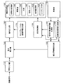
プロジェクタ20は、画像信号を入力する信号入力部110と、画像の歪みが補正されるように、入力された画像信号を補正する歪み補正部122と、補正された画像信号を出力する信号出力部160と、画像信号に基づき、画像を投写する投写手段の一種である画像投写部190と、キャリブレーション画像情報を生成するキャリブレーション画像情報生成部170とを含んで構成されている。
The
また、プロジェクタ20は、投写画像30を含む領域を、撮像面を介して撮像して撮像情報を生成する撮像部180と、撮像情報に基づき、センサー60の撮像面におけるスクリーン10の領域を抽出する投写対象領域情報生成部140と、撮像情報に基づき、センサー60の撮像面における投写画像30の領域を抽出する投写領域情報生成部150と、歪み補正用情報を生成する補正用情報生成部120とを含んで構成されている。なお、撮像部180は、センサー60を含む。
Further, the
また、画像投写部190は、空間光変調器191と、空間光変調器191を駆動する駆動部192と、光源193と、投写レンズ194と、投写レンズ194の画角を調整する画角調整部195と、投写レンズ194の光軸を調整するレンズシフト部196とを含んで構成されている。
The
駆動部192は、信号出力部160からの画像信号に基づき、空間光変調器191を駆動する。そして、画像投写部190は、光源193からの光を、空間光変調器191および投写レンズ194を介して投写する。
The
また、プロジェクタ20は、画角調整部195およびレンズシフト部196を制御する投写制御部130を含んで構成されている。
The
また、上述したプロジェクタ20の各部の機能をコンピュータに実装するためのハードウェアとしては、例えば、以下のものを適用できる。
Further, as hardware for mounting the functions of the respective units of the
図3は、本実施形態の一例に係るプロジェクタ20のハードウェアブロック図である。
FIG. 3 is a hardware block diagram of the
例えば、信号入力部110としては、例えばA/Dコンバーター930等、歪み補正部122としては、例えば画像処理回路970、RAM950、CPU910等、投写制御部130としては、例えばCPU910等、信号出力部160としては、例えばD/Aコンバーター940等、補正用情報生成部120、投写対象領域情報生成部140、投写領域情報生成部150およびキャリブレーション画像情報生成部170としては、例えば画像処理回路970、RAM950等、撮像部180としては、例えばCCDセンサー、CMOSセンサー、RGBセンサー等、空間光変調器191としては、例えば液晶パネル920、液晶パネル920を駆動する液晶ライトバルブ駆動ドライバを記憶するROM960等を用いて実装できる。
For example, the
なお、これらの各部はシステムバス980を介して相互に情報をやりとりすることが可能である。また、これらの各部は、その一部または全部を、回路のようにハードウェア的に実装してもよいし、ドライバのようにソフトウェア的に実装してもよい。
Note that these units can exchange information with each other via the
さらに、投写制御部130等としてコンピュータを機能させるためのプログラムを記憶した情報記憶媒体900からプログラムを読み取って投写制御部130等の機能をコンピュータに実装させてもよい。
Furthermore, the program may be read from an
このような情報記憶媒体900としては、例えば、CD−ROM、DVD−ROM、ROM、RAM、HDD等を適用でき、そのプログラムの読み取り方式は接触方式であっても、非接触方式であってもよい。
As such an
また、情報記憶媒体900に代えて、上述した各機能を実装するためのプログラム等を、伝送路を介してホスト装置等からダウンロードすることによって上述した各機能をコンピュータに実装することも可能である。
Further, instead of the
(画像処理の流れの説明)
次に、これらの各部を用いた画像処理の流れについて説明する。
(Description of the flow of image processing)
Next, the flow of image processing using these units will be described.
図4は、本実施形態の一例に係る画像処理の流れを示すフローチャートである。 FIG. 4 is a flowchart showing a flow of image processing according to an example of the present embodiment.
ユーザーは、手動またはプロジェクタ20の一般的な自動台形歪み補正機能等を使用して投写画像30の歪みを補正する(ステップS1)。例えば、補正用情報生成部120は、投写対象領域情報生成部140からの投写対象領域を示す情報と、投写領域情報生成部150からの投写画像の領域を示す情報とに基づき、画像の歪みを把握して歪み補正用情報を生成する。そして、歪み補正部122は、当該歪み補正用情報に基づいて補正用データを更新し、当該補正用データに基づき、画像信号を補正してもよい。
The user corrects the distortion of the projected
プロジェクタ20は、スクリーン10へ向けキャリブレーション画像を投写し、撮像部180は、キャリブレーション画像およびスクリーン10を含む領域を撮像して撮像情報を生成する(ステップS2)。
The
より具体的には、キャリブレーション画像情報生成部170は、全白(画像全体が白)の単色のキャリブレーション画像用の画像情報を生成し、信号出力部160は、当該画像情報のデジタル信号を画像投写部190に出力する。
More specifically, the calibration image
画像投写部190は、当該デジタル信号に基づき、スクリーン10へ向け全白のキャリブレーション画像を投写する。これにより、スクリーン10には、全白のキャリブレーション画像(投写画像30)が表示される。
The
撮像部180は、投写画像30およびスクリーン10を含む領域を、撮像面を介して撮像して撮像情報を生成する。ここで、撮像情報は、例えば、輝度値、XYZ値等の輝度値を生成可能な画像信号値をセンサー60の画素ごとに示す情報である。また、ここで、XYZ値とは、国際照明委員会(CIE)によって定められた国際規格で、機器独立色の一種の画像信号値である。
The
投写領域情報生成部150は、撮像部180からの撮像情報に基づき、撮像面における画像歪み補正後の投写画像30の4隅の座標を示す投写領域情報を生成する(ステップS3)。
Based on the imaging information from the
また、投写対象領域情報生成部140は、撮像部180からの撮像情報に基づき、撮像面におけるスクリーン10の4隅の座標を示す投写対象領域情報を生成する(ステップS4)。
Further, the projection target area
なお、キャリブレーション画像は単色の画像であるため、投写対象領域情報生成部140および投写領域情報生成部150は、画素ごとの輝度値の相違に基づいて投写画像30やスクリーン10の領域を把握することができる。
Since the calibration image is a monochrome image, the projection target area
また、投写制御部130は、投写画像30の大きさと表示位置を調整するために、スクリーン10の投写対象領域一杯に画像を表示するために画角調整部195を制御して画角を調整し、スクリーン10の適切な位置に画像を表示するためにレンズシフト部196を制御して投写レンズ194の光軸を調整する。まず、画角を調整する手法について説明する。
In addition, the
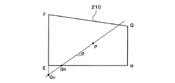
図5は、本実施形態の一例に係る撮像面における投写画像230とスクリーン210を示す模式図である。
FIG. 5 is a schematic diagram showing a projected
例えば、図5に示すように、1投写画像230の14隅の座標をABCD、投写画像230の対角線の交点をO、スクリーン210の4隅の座標をEFGH、スクリーン210の対角線の交点をPと仮定する。また、投写画像230の交点Oから頂点Aまでの線分(「基準線分ベクトル」という。)の水平方向に対する傾きをαと仮定する。
For example, as shown in FIG. 5, the coordinates of 14 corners of one projected
図6は、本実施形態の一例に係る比率と線分を示す模式図である。 FIG. 6 is a schematic diagram illustrating a ratio and a line segment according to an example of the present embodiment.
投写制御部130は、スクリーン210の対角線の交点Pから基準線分ベクトルの向き(傾きα)に直線を引いた場合のスクリーン210の辺EHと当該直線との交点Qhまでの線分(「拡大線分ベクトル」という。)を導出する。
The
なお、縦長のスクリーンの場合、当該直線と垂直方向の辺との交点Qvまでのスクリーン210の対角線の交点Pからの線分が拡大線分ベクトルとなる。また、線分QhPの長さと線分QvPの長さを比較して短いほうを拡大線分ベクトルとして採用してもよい。
In the case of a vertically long screen, the line segment from the intersection point P of the diagonal lines of the
投写制御部130は、拡大線分ベクトル/基準線分ベクトルを演算することによって倍率を導出する(ステップS5)。本実施例では、QhP/AOが倍率を示す数値となる。
The
さらに、投写制御部130は、当該倍率を入力して画角調整量を出力する関数に基づいて画角調整量を求める。そして、投写制御部130は、求めた画角調整量に基づき、画角調整部195を制御する(ステップS6)。これにより、プロジェクタ20は、上記倍率に拡大した画像を投写することができる。なお、投写制御部130は、関数以外にも、例えば、当該倍率と画角調整量とを関連づけたテーブル等を用いて画角調整量を求めてもよい。
Further, the
次に、投写レンズ194の光軸を調整する手法について説明する。
Next, a method for adjusting the optical axis of the
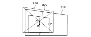
図7は、本実施形態の一例に係る投写画像230を拡大した状態を示す模式図である。また、図8は、本実施形態の一例に係るズーム状態による投写画像の相違を示す模式図である。
FIG. 7 is a schematic diagram illustrating an enlarged state of the projected
例えば、図8に示すように、ズーム状態がテレの場合の投写画像232においても、ズーム状態がワイドの場合の投写画像234においても位置が変化しない投写光の光軸の中心位置を点Lと仮定する。
For example, as shown in FIG. 8, the center position of the optical axis of the projection light whose position does not change in the
この場合、図7に示すように、点Lを基準として投写画像230をQhP/AO倍した投写画像236が拡大後の投写画像である。この投写画像236の対角線の交点をO’と仮定する。
In this case, as shown in FIG. 7, a projected
投写制御部130は、交点O’(O’x,O’y)と交点P(Px,Py)との位置関係に基づいて水平方向(x軸方向)のレンズシフト量Shを決定する。
例えば、Sh=g(Px−O’x)である。なお、ここで、gは、センサー座標(撮像面における座標)のずれ量を入力してレンズシフト量を出力する関数である。もちろん、投写制御部130は、センサー座標のずれ量とレンズシフト量とを関連づけたテーブル等を用いてレンズシフト量を求めてもよい。
The
For example, Sh = g (Px−O′x). Here, g is a function that inputs a shift amount of sensor coordinates (coordinates on the imaging surface) and outputs a lens shift amount. Of course, the
また、投写制御部130は、交点O’と交点Pとの位置関係に基づいて垂直方向(y軸方向)のレンズシフト量Svを決定する。例えば、Sv=h(Py−O’y)である。なお、ここで、hは、センサー座標のずれ量を入力してレンズシフト量を出力する関数である。
Further, the
また、投写制御部130は、このようにして求めたレンズシフト量ShおよびSvに基づき、レンズシフト部196を制御する(ステップS7)。
Further, the
このように、画角調整とレンズシフトを行うことにより、撮像面における投写画像は次のようになる。 As described above, by performing the angle of view adjustment and the lens shift, the projected image on the imaging surface is as follows.
図9は、本実施形態の一例に係る調整後の投写画像238を示す模式図である。
FIG. 9 is a schematic diagram showing an adjusted
図9に示すように、調整後の投写画像238は、元の投写画像230が拡大されて横方向の辺がスクリーン210の横方向の辺と一致した状態となる。また、投写画像238の対角線の交点は、スクリーン210の対角線の交点Pと一致する。
As shown in FIG. 9, the adjusted
このような状態でプロジェクタ20は、画像を投写する(ステップS8)。これにより、プロジェクタ20は、投写画像30の大きさと位置を自動的に調整して画像を投写することができる。
In such a state, the
以上のように、本実施形態によれば、プロジェクタ20は、投写領域情報と投写対象領域情報に基づいて投写領域と投写対象領域のそれぞれの位置と大きさと対角線の交点を把握することができる。そして、プロジェクタ20は、把握した対角線の交点等を基準として画像を拡大して投写することができる。
As described above, according to the present embodiment, the
これにより、プロジェクタ20は、スクリーン10等の投写対象物の投写対象領域を可能な限り有効に使用して画像を投写することができる。また、この場合、投写画像30のアスペクト比は元のままであるため、プロジェクタ20は、スクリーン10の形状によらずに正確な画像を投写することができる。すなわち、スクリーン10は、長方形に限定されず、正方形であってもよい。
Thereby, the
また、本実施形態によれば、1つのセンサー60を用いて画角調整とレンズシフトを同時に自動的に実行することができる。これにより、プロジェクタ20は、正確かつ高速に画像の位置と大きさを調整して画像を投写することができる。
Further, according to the present embodiment, the angle of view adjustment and the lens shift can be automatically executed simultaneously using one
(変形例)
なお、本発明の適用は上述した実施例に限定されない。
(Modification)
In addition, application of this invention is not limited to the Example mentioned above.
例えば、上述した実施例では、プロジェクタ20は、対角線の交点を基準として画像処理を行ったが、例えば、中心位置を基準として画像処理を行ってもよい。
For example, in the above-described embodiment, the
例えば、投写制御部130は、投写領域情報と、投写対象領域情報とに基づき、撮像面における歪み補正後の投写画像230の中心位置が、撮像面におけるスクリーン210の中心位置に移動するように、投写レンズ194の光軸を調整するレンズシフト部196を制御してもよい。
For example, based on the projection area information and the projection target area information, the
そして、投写制御部130は、投写画像230の中心位置が、スクリーン210の中心位置に移動した状態において、投写画像230の中心位置を経由する所定の直線(例えば、水平方向の直線、垂直方向の直線、対角線等)上における当該中心位置から投写画像230の辺までの長さと、当該直線上における当該中心位置からスクリーン210の辺までの長さとの比率に基づき、倍率を導出してもよい。
Then, the
さらに、投写制御部130は、当該倍率に基づき、投写レンズ194の画角を調整するレンズシフト部196を制御してもよい。
Furthermore, the
このような手法によっても、プロジェクタ20は、ズームとレンズシフトを同時に行って正確かつ高速に投写画像30の位置と大きさをスクリーン10に合わせて調整することができる。
Also by such a method, the
また、上述した実施例では、投写画像30の歪み補正後に画角調整とレンズシフトを行っているが、歪み補正が不要な位置にプロジェクタ20が配置されるような場合には歪み補正を行わなくてもよい。この場合においても、プロジェクタ20は、正確かつ高速に画像の位置と大きさを調整して画像を投写することができる。
In the above-described embodiment, the angle of view adjustment and the lens shift are performed after correcting the distortion of the projected
また、必ずしも投写画像30の辺をスクリーン10の投写対象領域の辺と厳密に一致させる必要はなく、若干投写画像30の辺の位置が投写対象領域の辺よりも外側になってもよいし、内側になってもよい。
In addition, the side of the
また、プロジェクタ20は、画角調整部195とレンズシフト部196を用いて投写画像30の位置と大きさをハードウェア的に調整する手法に代え、補正用データ等を用いてソフトウェア的に調整する手法を採用してもよい。
In addition, the
また、上述した実施例では、全白のキャリブレーション画像を用いたが、白以外の単色のキャリブレーション画像を用いてもよい。また、プロジェクタ20は、全黒(画像全体が黒)のキャリブレーション画像を投写して撮像し、全白のキャリブレーション画像を投写して撮像し、撮像情報に含まれる画素ごとの輝度値の比を比較し、所定値以上の輝度比となった画素領域を投写領域として抽出してもよい。
In the above-described embodiment, the calibration image of all white is used, but a single color calibration image other than white may be used. The
また、投写対象領域を有する投写対象物は、スクリーン10に限定されず、例えば、黒板、ホワイトボード等であってもよい。
Further, the projection target having the projection target area is not limited to the
また、上述した実施例では、画像処理システムとしてプロジェクタ20を用いたが、本発明は、プロジェクタ20以外にもCRT(Cathode Ray Tube)、LED(Light Emitting Diode)、EL(Electro Luminescence)等のディスプレイ用の画像処理システムにも有効である。
In the above-described embodiment, the
また、プロジェクタ20は、投写画像30の歪み、位置、大きさの補正だけでなく、投写画像30の明るさや色の補正を行ってもよい。
The
また、プロジェクタ20としては、例えば、液晶プロジェクタ、DMD(Digital Micromirror Device)を用いたプロジェクタ等を用いてもよい。なお、DMDは米国テキサスインスツルメンツ社の商標である。
Further, as the
また、上述したプロジェクタ20の機能は、例えば、プロジェクタ単体で実装してもよいし、複数の処理装置で分散して(例えば、プロジェクタとPCとで分散処理)実装してもよい。
Further, the functions of the
10 スクリーン(投写対象物、投写対象領域)、20 プロジェクタ(画像処理システム)、30 投写画像、60 センサー(撮像手段)、120 補正用情報生成部、140 投写対象領域情報生成部、150 投写領域情報生成部、170 キャリブレーション画像情報生成部、180 撮像部、190 画像投写部(投写手段)、900 情報記憶媒体
DESCRIPTION OF
Claims (13)
画角を調整する画角調整部と、投写レンズの光軸を調整するレンズシフト部とを有し、前記画像情報に基づき、矩形の投写対象領域へ向けキャリブレーション画像を投写する投写手段と、
投写された前記キャリブレーション画像と前記投写対象領域を含む領域を、撮像面を介して撮像して撮像情報を生成する撮像手段と、
前記撮像情報に基づき、前記撮像面における前記キャリブレーション画像の4隅の座標を示す投写領域情報を生成する投写領域情報生成手段と、
前記撮像情報に基づき、前記撮像面における前記投写対象領域の4隅の座標を示す投写対象領域情報を生成する投写対象領域情報生成手段と、
前記投写領域情報と、前記投写対象領域情報とに基づき、前記画角調整部と、前記レンズシフト部とを制御する投写制御手段と、
を含み、
前記投写制御手段は、
前記投写領域情報に基づき、前記撮像面における前記キャリブレーション画像の対角線の交点から1つの頂点までの線分を示す基準線分ベクトルを導出し、
前記投写対象領域情報に基づき、前記撮像面における前記投写対象領域の対角線の交点から前記基準線分ベクトルの向きに直線を引いた場合の当該投写対象領域の辺と当該直線との交点までの線分を示す拡大線分ベクトルを導出し、
当該拡大線分ベクトル/前記基準線分ベクトルを演算することによって倍率を導出し、
当該倍率に基づき前記画角調整部を制御し、
画角調整後の前記撮像面における前記キャリブレーション画像の対角線の交点と、前記撮像面における前記投写対象領域の対角線の交点とに基づき、前記キャリブレーション画像の対角線の交点が当該投写対象領域の対角線の交点に移動するように、前記レンズシフト部を制御することを特徴とする画像処理システム。 Calibration image information generating means for generating image information for displaying a calibration image;
A projection means for projecting a calibration image toward a rectangular projection target area, based on the image information, having an angle of view adjustment section for adjusting the angle of view and a lens shift section for adjusting the optical axis of the projection lens;
Imaging means for imaging the projected calibration image and the area including the projection target area via an imaging surface to generate imaging information;
Projection area information generating means for generating projection area information indicating the coordinates of the four corners of the calibration image on the imaging surface based on the imaging information;
Projection target area information generating means for generating projection target area information indicating the coordinates of the four corners of the projection target area on the imaging plane based on the imaging information;
Projection control means for controlling the angle of view adjustment unit and the lens shift unit based on the projection area information and the projection target area information;
Including
The projection control means includes
Based on the projection area information, a reference line segment vector indicating a line segment from an intersection of diagonal lines of the calibration image on the imaging surface to one vertex is derived,
Based on the projection target area information, a line from the intersection of the diagonal lines of the projection target area on the imaging surface to the intersection of the side of the projection target area and the straight line when a straight line is drawn in the direction of the reference line segment vector Deriving an expanded line vector that represents the minute,
Deriving a magnification by calculating the enlarged line segment vector / the reference line segment vector,
Controlling the angle-of-view adjustment unit based on the magnification,
Based on the intersection of the diagonal lines of the calibration image on the imaging surface after the adjustment of the angle of view and the intersection of the diagonal lines of the projection target area on the imaging surface, the intersection of the diagonal lines of the calibration image is the diagonal line of the projection target area. An image processing system that controls the lens shift unit so as to move to the intersection of the two.
画角を調整する画角調整部と、投写レンズの光軸を調整するレンズシフト部とを有し、前記画像情報に基づき、矩形の投写対象領域へ向けキャリブレーション画像を投写する投写手段と、
投写された前記キャリブレーション画像と前記投写対象領域を含む領域を、撮像面を介して撮像して撮像情報を生成する撮像手段と、
前記撮像情報に基づき、前記撮像面における前記キャリブレーション画像の4隅の座標を示す投写領域情報を生成する投写領域情報生成手段と、
前記撮像面における前記投写対象領域の4隅の座標を示す投写対象領域情報を生成する投写対象領域情報生成手段と、
前記投写領域情報と、前記投写対象領域情報とに基づき、前記画角調整部と、前記レンズシフト部とを制御する投写制御手段と、
を含み、
前記投写制御手段は、
前記投写領域情報と、前記投写対象領域情報とに基づき、前記撮像面における前記キャリブレーション画像の中心位置が、前記撮像面における前記投写対象領域の中心位置に移動するように、前記レンズシフト部を制御し、
前記撮像面における前記キャリブレーション画像の中心位置が、前記撮像面における前記投写対象領域の中心位置に移動した状態において、前記撮像面における前記キャリブレーション画像の中心位置を経由する所定の直線上における当該中心位置から当該キャリブレーション画像の辺までの長さと、当該直線上における当該中心位置から前記撮像面における前記投写対象領域の辺までの長さとの比率に基づき、倍率を導出し、
当該倍率に基づき前記画角調整部を制御することを特徴とする画像処理システム。 Calibration image information generating means for generating image information for displaying a calibration image;
A projection means for projecting a calibration image toward a rectangular projection target area, based on the image information, having an angle of view adjustment section for adjusting the angle of view and a lens shift section for adjusting the optical axis of the projection lens;
Imaging means for imaging the projected calibration image and the area including the projection target area via an imaging surface to generate imaging information;
Projection area information generating means for generating projection area information indicating the coordinates of the four corners of the calibration image on the imaging surface based on the imaging information;
Projection target area information generating means for generating projection target area information indicating the coordinates of the four corners of the projection target area on the imaging surface;
Projection control means for controlling the angle of view adjustment unit and the lens shift unit based on the projection area information and the projection target area information;
Including
The projection control means includes
Based on the projection area information and the projection target area information, the lens shift unit is arranged so that the center position of the calibration image on the imaging plane moves to the center position of the projection target area on the imaging plane. Control
In a state where the center position of the calibration image on the imaging surface has moved to the center position of the projection target area on the imaging surface, the calibration image on the predetermined straight line passing through the center position of the calibration image on the imaging surface Based on the ratio between the length from the center position to the side of the calibration image and the length from the center position on the straight line to the side of the projection target area on the imaging surface, the magnification is derived,
An image processing system that controls the angle-of-view adjustment unit based on the magnification.
前記キャリブレーション画像の歪みを補正する歪み補正手段を含み、
前記投写領域情報生成手段は、前記投写領域情報として、前記撮像情報に基づき、前記撮像面における前記キャリブレーション画像の歪み補正後の4隅の座標を示す情報を生成することを特徴とする画像処理システム。 In any one of Claims 1, 2.
Including distortion correction means for correcting distortion of the calibration image;
The projection area information generation unit generates, as the projection area information, information indicating coordinates of four corners after distortion correction of the calibration image on the imaging surface based on the imaging information. system.
画角を調整する画角調整部と、投写レンズの光軸を調整するレンズシフト部とを有し、前記画像情報に基づき、矩形の投写対象領域へ向けキャリブレーション画像を投写する投写手段と、
投写された前記キャリブレーション画像と前記投写対象領域を含む領域を、撮像面を介して撮像して撮像情報を生成する撮像手段と、
前記撮像情報に基づき、前記撮像面における前記キャリブレーション画像の4隅の座標を示す投写領域情報を生成する投写領域情報生成手段と、
前記撮像情報に基づき、前記撮像面における前記投写対象領域の4隅の座標を示す投写対象領域情報を生成する投写対象領域情報生成手段と、
前記投写領域情報と、前記投写対象領域情報とに基づき、前記画角調整部と、前記レンズシフト部とを制御する投写制御手段と、
を含み、
前記投写制御手段は、
前記投写領域情報に基づき、前記撮像面における前記キャリブレーション画像の対角線の交点から1つの頂点までの線分を示す基準線分ベクトルを導出し、
前記投写対象領域情報に基づき、前記撮像面における前記投写対象領域の対角線の交点から前記基準線分ベクトルの向きに直線を引いた場合の当該投写対象領域の辺と当該直線との交点までの線分を示す拡大線分ベクトルを導出し、
当該拡大線分ベクトル/前記基準線分ベクトルを演算することによって倍率を導出し、 当該倍率に基づき前記画角調整部を制御し、
画角調整後の前記撮像面における前記キャリブレーション画像の対角線の交点と、前記撮像面における前記投写対象領域の対角線の交点とに基づき、前記キャリブレーション画像の対角線の交点が当該投写対象領域の対角線の交点に移動するように、前記レンズシフト部を制御することを特徴とするプロジェクタ。 Calibration image information generating means for generating image information for displaying a calibration image;
A projection means for projecting a calibration image toward a rectangular projection target area, based on the image information, having an angle of view adjustment section for adjusting the angle of view and a lens shift section for adjusting the optical axis of the projection lens;
Imaging means for imaging the projected calibration image and the area including the projection target area via an imaging surface to generate imaging information;
Projection area information generating means for generating projection area information indicating the coordinates of the four corners of the calibration image on the imaging surface based on the imaging information;
Projection target area information generating means for generating projection target area information indicating the coordinates of the four corners of the projection target area on the imaging plane based on the imaging information;
Projection control means for controlling the angle of view adjustment unit and the lens shift unit based on the projection area information and the projection target area information;
Including
The projection control means includes
Based on the projection area information, a reference line segment vector indicating a line segment from an intersection of diagonal lines of the calibration image on the imaging surface to one vertex is derived,
Based on the projection target area information, a line from the intersection of the diagonal lines of the projection target area on the imaging surface to the intersection of the side of the projection target area and the straight line when a straight line is drawn in the direction of the reference line segment vector Deriving an expanded line vector that represents the minute,
Deriving a magnification by calculating the enlarged line segment vector / the reference line segment vector, controlling the angle-of-view adjustment unit based on the magnification,
Based on the intersection of the diagonal lines of the calibration image on the imaging surface after the adjustment of the angle of view and the intersection of the diagonal lines of the projection target area on the imaging surface, the intersection of the diagonal lines of the calibration image is the diagonal line of the projection target area. The projector is characterized in that the lens shift unit is controlled so as to move to the intersection.
画角を調整する画角調整部と、投写レンズの光軸を調整するレンズシフト部とを有し、前記画像情報に基づき、矩形の投写対象領域へ向けキャリブレーション画像を投写する投写手段と、
投写された前記キャリブレーション画像と前記投写対象領域を含む領域を、撮像面を介して撮像して撮像情報を生成する撮像手段と、
前記撮像情報に基づき、前記撮像面における前記キャリブレーション画像の4隅の座標を示す投写領域情報を生成する投写領域情報生成手段と、
前記撮像面における前記投写対象領域の4隅の座標を示す投写対象領域情報を生成する投写対象領域情報生成手段と、
前記投写領域情報と、前記投写対象領域情報とに基づき、前記画角調整部と、前記レンズシフト部とを制御する投写制御手段と、
を含み、
前記投写制御手段は、
前記投写領域情報と、前記投写対象領域情報とに基づき、前記撮像面における前記キャリブレーション画像の中心位置が、前記撮像面における前記投写対象領域の中心位置に移動するように、前記レンズシフト部を制御し、
前記撮像面における前記キャリブレーション画像の中心位置が、前記撮像面における前記投写対象領域の中心位置に移動した状態において、前記撮像面における前記キャリブレーション画像の中心位置を経由する所定の直線上における当該中心位置から当該キャリブレーション画像の辺までの長さと、当該直線上における当該中心位置から前記撮像面における前記投写対象領域の辺までの長さとの比率に基づき、倍率を導出し、
当該倍率に基づき前記画角調整部を制御することを特徴とするプロジェクタ。 Calibration image information generating means for generating image information for displaying a calibration image;
A projection means for projecting a calibration image toward a rectangular projection target area, based on the image information, having an angle of view adjustment section for adjusting the angle of view and a lens shift section for adjusting the optical axis of the projection lens;
Imaging means for imaging the projected calibration image and the area including the projection target area via an imaging surface to generate imaging information;
Projection area information generating means for generating projection area information indicating the coordinates of the four corners of the calibration image on the imaging surface based on the imaging information;
Projection target area information generating means for generating projection target area information indicating the coordinates of the four corners of the projection target area on the imaging surface;
Projection control means for controlling the angle of view adjustment unit and the lens shift unit based on the projection area information and the projection target area information;
Including
The projection control means includes
Based on the projection area information and the projection target area information, the lens shift unit is arranged so that the center position of the calibration image on the imaging plane moves to the center position of the projection target area on the imaging plane. Control
In a state where the center position of the calibration image on the imaging surface has moved to the center position of the projection target area on the imaging surface, the calibration image on the predetermined straight line passing through the center position of the calibration image on the imaging surface Based on the ratio between the length from the center position to the side of the calibration image and the length from the center position on the straight line to the side of the projection target area on the imaging surface, the magnification is derived,
A projector that controls the angle-of-view adjustment unit based on the magnification.
前記キャリブレーション画像の歪みを補正する歪み補正手段を含み、
前記投写領域情報生成手段は、前記投写領域情報として、前記撮像情報に基づき、前記撮像面における前記キャリブレーション画像の歪み補正後の4隅の座標を示す情報を生成することを特徴とするプロジェクタ。 In any one of Claims 4 and 5,
Including distortion correction means for correcting distortion of the calibration image;
The projection area information generation unit generates information indicating coordinates of four corners after distortion correction of the calibration image on the imaging surface based on the imaging information as the projection area information.
コンピュータを、
キャリブレーション画像を表示するための画像情報を生成するキャリブレーション画像情報生成手段と、
画角を調整する画角調整部と、投写レンズの光軸を調整するレンズシフト部とを有する投写部であって、前記画像情報に基づき、矩形の投写対象領域へ向けキャリブレーション画像を投写する投写部を制御する投写制御手段と、
投写された前記キャリブレーション画像と前記投写対象領域を含む領域を、撮像面を介して撮像して撮像情報を生成する撮像部を制御する撮像制御手段と、
前記撮像情報に基づき、前記撮像面における前記キャリブレーション画像の4隅の座標を示す投写領域情報を生成する投写領域情報生成手段と、
前記撮像情報に基づき、前記撮像面における前記投写対象領域の4隅の座標を示す投写対象領域情報を生成する投写対象領域情報生成手段として機能させ、
前記投写制御手段は、
前記投写領域情報に基づき、前記撮像面における歪み前記キャリブレーション画像の対角線の交点から1つの頂点までの線分を示す基準線分ベクトルを導出し、
前記投写対象領域情報に基づき、前記撮像面における前記投写対象領域の対角線の交点から前記基準線分ベクトルの向きに直線を引いた場合の当該投写対象領域の辺と当該直線との交点までの線分を示す拡大線分ベクトルを導出し、
当該拡大線分ベクトル/前記基準線分ベクトルを演算することによって倍率を導出し、 当該倍率に基づき前記画角調整部を制御し、
画角調整後の前記撮像面における前記キャリブレーション画像の対角線の交点と、前記撮像面における前記投写対象領域の対角線の交点とに基づき、前記キャリブレーション画像の対角線の交点が当該投写対象領域の対角線の交点に移動するように、前記レンズシフト部を制御することを特徴とするプログラム。 A computer-readable program,
Computer
Calibration image information generating means for generating image information for displaying a calibration image;
A projection unit having a field angle adjustment unit for adjusting a field angle and a lens shift unit for adjusting an optical axis of a projection lens, and projects a calibration image toward a rectangular projection target region based on the image information. Projection control means for controlling the projection unit;
An imaging control unit that controls an imaging unit that generates an imaging information by imaging an area including the projected calibration image and the projection target area via an imaging surface;
Projection area information generating means for generating projection area information indicating the coordinates of the four corners of the calibration image on the imaging surface based on the imaging information;
Based on the imaging information, function as projection target area information generating means for generating projection target area information indicating the coordinates of the four corners of the projection target area on the imaging surface;
The projection control means includes
Deriving a reference line segment vector indicating a line segment from an intersection of diagonal lines of the calibration image to one vertex based on the projection area information,
Based on the projection target area information, a line from the intersection of the diagonal lines of the projection target area on the imaging surface to the intersection of the side of the projection target area and the straight line when a straight line is drawn in the direction of the reference line segment vector Deriving an expanded line vector that represents the minute,
Deriving a magnification by calculating the enlarged line segment vector / the reference line segment vector, controlling the angle-of-view adjustment unit based on the magnification,
Based on the intersection of the diagonal lines of the calibration image on the imaging surface after the adjustment of the angle of view and the intersection of the diagonal lines of the projection target area on the imaging surface, the intersection of the diagonal lines of the calibration image is the diagonal line of the projection target area. A program for controlling the lens shift unit so as to move to the intersection of the two.
コンピュータを、
キャリブレーション画像を表示するための画像情報を生成するキャリブレーション画像情報生成手段と、
画角を調整する画角調整部と、投写レンズの光軸を調整するレンズシフト部とを有する投写部であって、前記画像情報に基づき、矩形の投写対象領域へ向けキャリブレーション画像を投写する投写部を制御する投写制御手段と、
投写された前記キャリブレーション画像と前記投写対象領域を含む領域を、撮像面を介して撮像して撮像情報を生成する撮像部を制御する撮像制御手段と、
前記撮像情報に基づき、前記撮像面における前記キャリブレーション画像の4隅の座標を示す投写領域情報を生成する投写領域情報生成手段と、
前記撮像面における前記投写対象領域の4隅の座標を示す投写対象領域情報を生成する投写対象領域情報生成手段として機能させ、
前記投写制御手段は、
前記投写領域情報と、前記投写対象領域情報とに基づき、前記撮像面における前記キャリブレーション画像の中心位置が、前記撮像面における前記投写対象領域の中心位置に移動するように、前記レンズシフト部を制御し、
前記撮像面における前記キャリブレーション画像の中心位置が、前記撮像面における前記投写対象領域の中心位置に移動した状態において、前記撮像面における前記キャリブレーション画像の中心位置を経由する所定の直線上における当該中心位置から当該キャリブレーション画像の辺までの長さと、当該直線上における当該中心位置から前記撮像面における前記投写対象領域の辺までの長さとの比率に基づき、倍率を導出し、
当該倍率に基づき前記画角調整部を制御することを特徴とするプログラム。 A computer-readable program,
Computer
Calibration image information generating means for generating image information for displaying a calibration image;
A projection unit having a field angle adjustment unit for adjusting a field angle and a lens shift unit for adjusting an optical axis of a projection lens, and projects a calibration image toward a rectangular projection target region based on the image information. Projection control means for controlling the projection unit;
An imaging control unit that controls an imaging unit that generates an imaging information by imaging an area including the projected calibration image and the projection target area via an imaging surface;
Projection area information generating means for generating projection area information indicating the coordinates of the four corners of the calibration image on the imaging surface based on the imaging information;
Function as projection target area information generating means for generating projection target area information indicating the coordinates of the four corners of the projection target area on the imaging surface;
The projection control means includes
Based on the projection area information and the projection target area information, the lens shift unit is arranged so that the center position of the calibration image on the imaging plane moves to the center position of the projection target area on the imaging plane. Control
In a state where the center position of the calibration image on the imaging surface has moved to the center position of the projection target area on the imaging surface, the calibration image on the predetermined straight line passing through the center position of the calibration image on the imaging surface Based on the ratio between the length from the center position to the side of the calibration image and the length from the center position on the straight line to the side of the projection target area on the imaging surface, the magnification is derived,
A program for controlling the angle-of-view adjustment unit based on the magnification.
前記キャリブレーション画像の歪みを補正する歪み補正手段としてコンピュータを機能させ、
前記投写領域情報生成手段は、前記投写領域情報として、前記撮像情報に基づき、前記撮像面における前記キャリブレーション画像の歪み補正後の4隅の座標を示す情報を生成することを特徴とするプログラム。 In any one of Claims 7 and 8,
Causing a computer to function as distortion correction means for correcting distortion of the calibration image;
The projection area information generating unit generates information indicating coordinates of four corners after distortion correction of the calibration image on the imaging surface based on the imaging information as the projection area information.
請求項7〜9のいずれかに記載のプログラムを記憶したことを特徴とする情報記憶媒体。 An information storage medium storing a computer-readable program,
An information storage medium storing the program according to claim 7.
投写した前記キャリブレーション画像と前記投写対象領域を含む領域を、撮像面を介して撮像して撮像情報を生成し、
当該撮像情報に基づき、前記撮像面における前記キャリブレーション画像の4隅の座標を示す投写領域情報を生成するとともに、前記撮像面における前記投写対象領域の4隅の座標を示す投写対象領域情報を生成し、
前記投写領域情報に基づき、前記撮像面における前記キャリブレーション画像の対角線の交点から1つの頂点までの線分を示す基準線分ベクトルを導出し、
前記投写対象領域情報に基づき、前記撮像面における前記投写対象領域の対角線の交点から前記基準線分ベクトルの向きに直線を引いた場合の当該投写対象領域の辺と当該直線との交点までの線分を示す拡大線分ベクトルを導出し、
当該拡大線分ベクトル/前記基準線分ベクトルを演算することによって倍率を導出し、
当該倍率に基づき、投写部の画角を調整する画角調整部を制御し、
画角調整後の前記撮像面における前記キャリブレーション画像の対角線の交点と、前記撮像面における前記投写対象領域の対角線の交点とに基づき、前記キャリブレーション画像の対角線の交点が当該投写対象領域の対角線の交点に移動するように、前記投写部の光軸を調整するレンズシフト部を制御することを特徴とする画像処理方法。 Project the calibration image onto the rectangular projection area,
Imaging the projected calibration image and the area including the projection target area via an imaging surface to generate imaging information;
Based on the imaging information, projection area information indicating the coordinates of the four corners of the calibration image on the imaging plane is generated, and projection target area information indicating the coordinates of the four corners of the projection target area on the imaging plane is generated. And
Based on the projection area information, a reference line segment vector indicating a line segment from an intersection of diagonal lines of the calibration image on the imaging surface to one vertex is derived,
Based on the projection target area information, a line from the intersection of the diagonal lines of the projection target area on the imaging surface to the intersection of the side of the projection target area and the straight line when a straight line is drawn in the direction of the reference line segment vector Deriving an expanded line vector that represents the minute,
Deriving a magnification by calculating the enlarged line segment vector / the reference line segment vector,
Based on the magnification, control the angle of view adjustment unit that adjusts the angle of view of the projection unit,
Based on the intersection of the diagonal lines of the calibration image on the imaging surface after the adjustment of the angle of view and the intersection of the diagonal lines of the projection target area on the imaging surface, the intersection of the diagonal lines of the calibration image is the diagonal line of the projection target area. An image processing method comprising: controlling a lens shift unit that adjusts an optical axis of the projection unit so as to move to the intersection of the projection unit.
投写した前記キャリブレーション画像と前記投写対象領域を含む領域を、撮像面を介して撮像して撮像情報を生成し、
当該撮像情報に基づき、前記撮像面における前記キャリブレーション画像の4隅の座標を示す投写領域情報を生成するとともに、前記撮像面における前記投写対象領域の4隅の座標を示す投写対象領域情報を生成し、
前記投写領域情報と、前記投写対象領域情報とに基づき、前記撮像面における前記キャリブレーション画像の中心位置が、前記撮像面における前記投写対象領域の中心位置に移動するように、投写部の光軸を調整するレンズシフト部を制御し、
前記撮像面における前記キャリブレーション画像の中心位置が、前記撮像面における前記投写対象領域の中心位置に移動した状態において、前記撮像面における前記キャリブレーション画像の中心位置を経由する所定の直線上における当該中心位置から当該キャリブレーション画像の辺までの長さと、当該直線上における当該中心位置から前記撮像面における前記投写対象領域の辺までの長さとの比率に基づき、倍率を導出し、
当該倍率に基づき、前記投写部の画角を調整する画角調整部を制御することを特徴とする画像処理方法。 Project the calibration image onto the rectangular projection area,
Imaging the projected calibration image and the area including the projection target area via an imaging surface to generate imaging information;
Based on the imaging information, projection area information indicating the coordinates of the four corners of the calibration image on the imaging plane is generated, and projection target area information indicating the coordinates of the four corners of the projection target area on the imaging plane is generated. And
Based on the projection area information and the projection target area information, the optical axis of the projection unit is moved so that the center position of the calibration image on the imaging plane moves to the center position of the projection target area on the imaging plane. Control the lens shift part to adjust the
In a state where the center position of the calibration image on the imaging surface has moved to the center position of the projection target area on the imaging surface, the calibration image on the predetermined straight line passing through the center position of the calibration image on the imaging surface Based on the ratio between the length from the center position to the side of the calibration image and the length from the center position on the straight line to the side of the projection target area on the imaging surface, the magnification is derived,
An image processing method comprising: controlling an angle-of-view adjusting unit that adjusts an angle of view of the projection unit based on the magnification.
前記投写領域情報として、前記撮像情報に基づき、前記撮像面における前記キャリブレーション画像の歪み補正後の4隅の座標を示す情報を生成することを特徴とする画像処理方法。 In any one of Claims 11 and 12,
An image processing method comprising: generating information indicating coordinates of four corners after distortion correction of the calibration image on the imaging surface based on the imaging information as the projection area information.
Priority Applications (8)
| Application Number | Priority Date | Filing Date | Title |
|---|---|---|---|
| JP2004009026A JP3846592B2 (en) | 2003-06-26 | 2004-01-16 | Image processing system, projector, program, information storage medium, and image processing method |
| US10/858,381 US6932480B2 (en) | 2003-06-26 | 2004-06-02 | Image processing system, projector, program, information storage medium and image processing method |
| EP08075513A EP1954061A3 (en) | 2003-06-26 | 2004-06-07 | Image processing system, projector, information storage medium and image processing method |
| EP04253381A EP1492355B1 (en) | 2003-06-26 | 2004-06-07 | Image processing system, projector, information storage medium and image processing method |
| DE602004015370T DE602004015370D1 (en) | 2003-06-26 | 2004-06-07 | and image processing method |
| TW093116755A TWI255414B (en) | 2003-06-26 | 2004-06-10 | Image processing system, projector, data memory medium and image processing method |
| CNB2004100483164A CN100470358C (en) | 2003-06-26 | 2004-06-17 | Image processing system, projector,and image processing method |
| KR1020040045410A KR100571175B1 (en) | 2003-06-26 | 2004-06-18 | Image processing system, projector, information storage medium and image processing method |
Applications Claiming Priority (2)
| Application Number | Priority Date | Filing Date | Title |
|---|---|---|---|
| JP2003182734 | 2003-06-26 | ||
| JP2004009026A JP3846592B2 (en) | 2003-06-26 | 2004-01-16 | Image processing system, projector, program, information storage medium, and image processing method |
Publications (2)
| Publication Number | Publication Date |
|---|---|
| JP2005039769A JP2005039769A (en) | 2005-02-10 |
| JP3846592B2 true JP3846592B2 (en) | 2006-11-15 |
Family
ID=33422209
Family Applications (1)
| Application Number | Title | Priority Date | Filing Date |
|---|---|---|---|
| JP2004009026A Expired - Fee Related JP3846592B2 (en) | 2003-06-26 | 2004-01-16 | Image processing system, projector, program, information storage medium, and image processing method |
Country Status (7)
| Country | Link |
|---|---|
| US (1) | US6932480B2 (en) |
| EP (2) | EP1954061A3 (en) |
| JP (1) | JP3846592B2 (en) |
| KR (1) | KR100571175B1 (en) |
| CN (1) | CN100470358C (en) |
| DE (1) | DE602004015370D1 (en) |
| TW (1) | TWI255414B (en) |
Families Citing this family (56)
| Publication number | Priority date | Publication date | Assignee | Title |
|---|---|---|---|---|
| JP4150924B2 (en) * | 2003-07-02 | 2008-09-17 | セイコーエプソン株式会社 | Image processing system, projector, program, information storage medium, and image processing method |
| JP3846592B2 (en) * | 2003-06-26 | 2006-11-15 | セイコーエプソン株式会社 | Image processing system, projector, program, information storage medium, and image processing method |
| JP4055010B2 (en) * | 2003-09-26 | 2008-03-05 | セイコーエプソン株式会社 | Image processing system, projector, program, information storage medium, and image processing method |
| JP3928623B2 (en) * | 2004-02-27 | 2007-06-13 | カシオ計算機株式会社 | Projection apparatus, distance measurement processing method, and program |
| JP4006601B2 (en) * | 2004-03-29 | 2007-11-14 | セイコーエプソン株式会社 | Image processing system, projector, program, information storage medium, and image processing method |
| US20060028462A1 (en) * | 2004-08-04 | 2006-02-09 | Konica Minolta Medical & Graphic, Inc. | Calibration method |
| US7946718B2 (en) * | 2004-09-24 | 2011-05-24 | Tte Technology, Inc. | System and method for optical calibration of a picture modulator |
| JP2006121240A (en) * | 2004-10-20 | 2006-05-11 | Sharp Corp | Image projection method, projector, and computer program |
| JP2006163360A (en) * | 2004-11-11 | 2006-06-22 | Casio Comput Co Ltd | Projector device, projecting method and projection control program |
| JP4232042B2 (en) | 2005-01-07 | 2009-03-04 | セイコーエプソン株式会社 | Projection control system, projector, program, information storage medium, and projection control method |
| JP4380557B2 (en) * | 2005-02-15 | 2009-12-09 | カシオ計算機株式会社 | Projector, chart image display method and program |
| JP4196955B2 (en) * | 2005-02-22 | 2008-12-17 | セイコーエプソン株式会社 | Projector and processing line determination method |
| JP4244040B2 (en) * | 2005-03-10 | 2009-03-25 | 任天堂株式会社 | Input processing program and input processing apparatus |
| JP4363354B2 (en) * | 2005-04-06 | 2009-11-11 | セイコーエプソン株式会社 | Distortion correction processing for projectors |
| EP1898260A4 (en) * | 2005-06-30 | 2014-07-09 | Ricoh Co Ltd | Projection image display device |
| US20070025273A1 (en) * | 2005-07-29 | 2007-02-01 | Chung Yau W | Methods and systems for detecting video signals and sources |
| US7701518B2 (en) * | 2005-07-29 | 2010-04-20 | Optoma Technology, Inc. | Methods and systems for displaying video in multiple aspect ratios |
| US20070024823A1 (en) * | 2005-07-29 | 2007-02-01 | Optoma Technology, Inc. | Methods and systems for improving operation of a video projector |
| US8089567B2 (en) | 2005-07-29 | 2012-01-03 | Optoma Technology, Inc. | Methods and systems for displaying video on an adjustable screen |
| US20070024764A1 (en) * | 2005-07-29 | 2007-02-01 | Optoma Technology, Inc. | Methods and systems that compensate for distortion introduced by anamorphic lenses in a video projector |
| US7357514B2 (en) * | 2005-07-29 | 2008-04-15 | Optoma Technology, Inc. | Methods and systems for improving operation of a video projector |
| US7434937B2 (en) | 2005-07-29 | 2008-10-14 | Optoma Technology, Inc. | Methods and systems for calibrating rear projection video |
| JP5087830B2 (en) * | 2005-09-09 | 2012-12-05 | セイコーエプソン株式会社 | Projection system |
| JP2007078821A (en) * | 2005-09-12 | 2007-03-29 | Casio Comput Co Ltd | Projector, projecting method and program |
| US20070091435A1 (en) * | 2005-10-21 | 2007-04-26 | Hewlett-Packard Development Company, L.P. | Image pixel transformation |
| JP4652219B2 (en) * | 2005-12-14 | 2011-03-16 | Necディスプレイソリューションズ株式会社 | Projector screen |
| CN101322402B (en) * | 2005-12-22 | 2010-09-15 | 松下电器产业株式会社 | Image projection device, control method and semiconductor device |
| JP3953500B1 (en) * | 2006-02-07 | 2007-08-08 | シャープ株式会社 | Image projection method and projector |
| JP5116288B2 (en) * | 2006-11-16 | 2013-01-09 | 株式会社リコー | Image projection apparatus and image projection method |
| US7544919B2 (en) | 2006-11-20 | 2009-06-09 | Red.Com, Inc. | Focus assist system and method |
| US20080170209A1 (en) * | 2007-01-12 | 2008-07-17 | Seiko Epson Corporation | Image Display System, Image Output System, and Image Display Method |
| JP5088018B2 (en) * | 2007-06-28 | 2012-12-05 | 富士ゼロックス株式会社 | Image processing apparatus and control program |
| US7857461B2 (en) * | 2007-11-06 | 2010-12-28 | Panasonic Corporation | Projector and projection method |
| JP2009134069A (en) * | 2007-11-30 | 2009-06-18 | Seiko Epson Corp | Projection image display position control device, projection image display control method, and projection system |
| JP5282434B2 (en) * | 2008-04-01 | 2013-09-04 | セイコーエプソン株式会社 | Image processing apparatus, image display apparatus, and image processing method |
| KR101527014B1 (en) * | 2008-12-02 | 2015-06-09 | 엘지전자 주식회사 | Mobile terminal and method for controlling display thereof |
| JP5541031B2 (en) * | 2010-09-16 | 2014-07-09 | セイコーエプソン株式会社 | Projector and projector control method |
| JP5754124B2 (en) * | 2010-12-14 | 2015-07-29 | セイコーエプソン株式会社 | Projector and control method |
| JP5924020B2 (en) * | 2012-02-16 | 2016-05-25 | セイコーエプソン株式会社 | Projector and projector control method |
| JP6208930B2 (en) * | 2012-08-14 | 2017-10-04 | キヤノン株式会社 | Projection apparatus, control method therefor, program, and storage medium |
| JP6127443B2 (en) * | 2012-10-19 | 2017-05-17 | カシオ計算機株式会社 | Projection apparatus and projection state adjustment method |
| US9514716B2 (en) * | 2012-10-19 | 2016-12-06 | Casio Computer Co., Ltd. | Projection apparatus, projection control apparatus, projection system, and projection state adjustment method |
| JP6525612B2 (en) * | 2015-01-30 | 2019-06-05 | キヤノン株式会社 | Image projection device |
| TWI592020B (en) * | 2016-08-23 | 2017-07-11 | 國立臺灣科技大學 | Image correction method of projector and image correction system |
| CN106412540B (en) * | 2016-11-18 | 2019-01-22 | 四川长虹电器股份有限公司 | Projection display system and its automatic aligning method |
| JP6515949B2 (en) * | 2017-04-12 | 2019-05-22 | カシオ計算機株式会社 | Projection apparatus and projection state adjustment method |
| US10349025B2 (en) * | 2017-07-27 | 2019-07-09 | Seiko Epson Corporation | Projector and method of controlling projector |
| JP7070049B2 (en) * | 2017-07-27 | 2022-05-18 | セイコーエプソン株式会社 | Projector and projector control method |
| CN108171674B (en) * | 2018-01-15 | 2020-07-14 | 西北工业大学 | Vision correction method for projector image with any visual angle |
| US11240475B2 (en) | 2018-04-17 | 2022-02-01 | Sony Corporation | Information processing apparatus and method |
| CN108769666A (en) * | 2018-05-03 | 2018-11-06 | 深圳睿晟自动化技术有限公司 | Optical center localization method, device, terminal device and the storage medium of light emitting module |
| JP2020136909A (en) * | 2019-02-20 | 2020-08-31 | セイコーエプソン株式会社 | Adjustment method of projection image, and projection device |
| CN113259637B (en) * | 2020-02-12 | 2022-07-12 | 青岛海信激光显示股份有限公司 | Projection image correction method and laser projection system |
| CN112004072B (en) * | 2020-07-31 | 2022-05-03 | 海尔优家智能科技(北京)有限公司 | Projection image detection method and device |
| CN113540711B (en) * | 2021-07-07 | 2023-05-30 | 电子科技大学 | Cylindrical spiral conformal liquid crystal phase shifter |
| CN116366821B (en) * | 2023-06-01 | 2023-08-08 | 深圳市橙子数字科技有限公司 | Automatic positioning method and device, storage medium and electronic equipment |
Family Cites Families (17)
| Publication number | Priority date | Publication date | Assignee | Title |
|---|---|---|---|---|
| JPH1141428A (en) | 1997-07-18 | 1999-02-12 | Canon Inc | Image reader and image reading method |
| JP4089051B2 (en) * | 1998-02-18 | 2008-05-21 | セイコーエプソン株式会社 | Image processing apparatus and image processing method |
| JP4493113B2 (en) * | 1999-01-29 | 2010-06-30 | 株式会社リコー | Projector and projection image correction apparatus |
| JP2000241874A (en) | 1999-02-19 | 2000-09-08 | Nec Corp | Method and device for automatically adjusting screen position for projector |
| US6753907B1 (en) * | 1999-12-23 | 2004-06-22 | Justsystem Corporation | Method and apparatus for automatic keystone correction |
| JP4150924B2 (en) * | 2003-07-02 | 2008-09-17 | セイコーエプソン株式会社 | Image processing system, projector, program, information storage medium, and image processing method |
| US6520647B2 (en) * | 2000-08-17 | 2003-02-18 | Mitsubishi Electric Research Laboratories Inc. | Automatic keystone correction for projectors with arbitrary orientation |
| US7352913B2 (en) | 2001-06-12 | 2008-04-01 | Silicon Optix Inc. | System and method for correcting multiple axis displacement distortion |
| TW508474B (en) * | 2001-11-15 | 2002-11-01 | Coretronic Corp | System and method for improvement of asymmetric projection illumination |
| JP3761491B2 (en) * | 2002-05-10 | 2006-03-29 | Necビューテクノロジー株式会社 | Projection image distortion correction method, distortion correction program, and projection-type image display device |
| JP3844075B2 (en) * | 2003-01-17 | 2006-11-08 | セイコーエプソン株式会社 | Image processing system, projector, program, information storage medium, and image processing method |
| JP3846592B2 (en) * | 2003-06-26 | 2006-11-15 | セイコーエプソン株式会社 | Image processing system, projector, program, information storage medium, and image processing method |
| JP2005030363A (en) * | 2003-07-11 | 2005-02-03 | Denso Corp | Motor-driven fan system for vehicle |
| JP3969363B2 (en) * | 2003-07-30 | 2007-09-05 | カシオ計算機株式会社 | Projector and projection image correction method for projector |
| JP3951984B2 (en) * | 2003-08-22 | 2007-08-01 | 日本電気株式会社 | Image projection method and image projection apparatus |
| JP4020043B2 (en) * | 2003-08-25 | 2007-12-12 | カシオ計算機株式会社 | Projection apparatus, projection method, and program |
| JP3827662B2 (en) * | 2003-09-10 | 2006-09-27 | Necビューテクノロジー株式会社 | Projection display |
-
2004
- 2004-01-16 JP JP2004009026A patent/JP3846592B2/en not_active Expired - Fee Related
- 2004-06-02 US US10/858,381 patent/US6932480B2/en not_active Expired - Fee Related
- 2004-06-07 EP EP08075513A patent/EP1954061A3/en not_active Withdrawn
- 2004-06-07 DE DE602004015370T patent/DE602004015370D1/en active Active
- 2004-06-07 EP EP04253381A patent/EP1492355B1/en not_active Expired - Fee Related
- 2004-06-10 TW TW093116755A patent/TWI255414B/en not_active IP Right Cessation
- 2004-06-17 CN CNB2004100483164A patent/CN100470358C/en not_active Expired - Fee Related
- 2004-06-18 KR KR1020040045410A patent/KR100571175B1/en not_active IP Right Cessation
Also Published As
| Publication number | Publication date |
|---|---|
| TWI255414B (en) | 2006-05-21 |
| KR100571175B1 (en) | 2006-04-13 |
| CN100470358C (en) | 2009-03-18 |
| EP1954061A2 (en) | 2008-08-06 |
| KR20050001336A (en) | 2005-01-06 |
| EP1954061A3 (en) | 2008-10-22 |
| JP2005039769A (en) | 2005-02-10 |
| US6932480B2 (en) | 2005-08-23 |
| DE602004015370D1 (en) | 2008-09-11 |
| EP1492355A2 (en) | 2004-12-29 |
| US20050018144A1 (en) | 2005-01-27 |
| EP1492355B1 (en) | 2008-07-30 |
| TW200508941A (en) | 2005-03-01 |
| CN1577048A (en) | 2005-02-09 |
| EP1492355A3 (en) | 2005-10-05 |
Similar Documents
| Publication | Publication Date | Title |
|---|---|---|
| JP3846592B2 (en) | Image processing system, projector, program, information storage medium, and image processing method | |
| JP3844076B2 (en) | Image processing system, projector, program, information storage medium, and image processing method | |
| JP3879858B2 (en) | Image processing system, projector, and image processing method | |
| US7524070B2 (en) | Projection control system, projector and projection control method | |
| JP3925521B2 (en) | Keystone correction using part of the screen edge | |
| TWI249351B (en) | Image processing system, projector, and image processing method | |
| US7422331B2 (en) | Image processing system, projector, and image processing method | |
| JP3994290B2 (en) | Image processing system, projector, program, information storage medium, and image processing method | |
| US7949202B2 (en) | Image processing system, projector, and image processing method | |
| JP2006121240A (en) | Image projection method, projector, and computer program | |
| JP2011199717A (en) | Projection type display device and image display method | |
| JP5110260B2 (en) | Projector, program, information storage medium, and image distortion correction method | |
| TWI695625B (en) | Image calibration method and projector system | |
| JP2005286573A (en) | Image processing system, projector, program, information storage medium, and image processing method | |
| JP5354163B2 (en) | Projector, program and information storage medium | |
| WO2012172655A1 (en) | Projector and control method thereof | |
| JP2009135972A (en) | Projector, program, and information storage medium | |
| JP2004347775A (en) | Image processing system, projector, program, information storage medium and image processing method | |
| JP2006217370A (en) | Image processing system, projector, program, information storage medium, and image processing method |
Legal Events
| Date | Code | Title | Description |
|---|---|---|---|
| A621 | Written request for application examination |
Free format text: JAPANESE INTERMEDIATE CODE: A621 Effective date: 20050204 |
|
| RD04 | Notification of resignation of power of attorney |
Free format text: JAPANESE INTERMEDIATE CODE: A7424 Effective date: 20051221 |
|
| TRDD | Decision of grant or rejection written | ||
| A01 | Written decision to grant a patent or to grant a registration (utility model) |
Free format text: JAPANESE INTERMEDIATE CODE: A01 Effective date: 20060802 |
|
| A61 | First payment of annual fees (during grant procedure) |
Free format text: JAPANESE INTERMEDIATE CODE: A61 Effective date: 20060815 |
|
| R150 | Certificate of patent or registration of utility model |
Free format text: JAPANESE INTERMEDIATE CODE: R150 |
|
| FPAY | Renewal fee payment (event date is renewal date of database) |
Free format text: PAYMENT UNTIL: 20090901 Year of fee payment: 3 |
|
| FPAY | Renewal fee payment (event date is renewal date of database) |
Free format text: PAYMENT UNTIL: 20100901 Year of fee payment: 4 |
|
| FPAY | Renewal fee payment (event date is renewal date of database) |
Free format text: PAYMENT UNTIL: 20100901 Year of fee payment: 4 |
|
| FPAY | Renewal fee payment (event date is renewal date of database) |
Free format text: PAYMENT UNTIL: 20110901 Year of fee payment: 5 |
|
| FPAY | Renewal fee payment (event date is renewal date of database) |
Free format text: PAYMENT UNTIL: 20120901 Year of fee payment: 6 |
|
| FPAY | Renewal fee payment (event date is renewal date of database) |
Free format text: PAYMENT UNTIL: 20130901 Year of fee payment: 7 |
|
| S531 | Written request for registration of change of domicile |
Free format text: JAPANESE INTERMEDIATE CODE: R313531 |
|
| R350 | Written notification of registration of transfer |
Free format text: JAPANESE INTERMEDIATE CODE: R350 |
|
| LAPS | Cancellation because of no payment of annual fees |