JP3844075B2 - Image processing system, projector, program, information storage medium, and image processing method - Google Patents
Image processing system, projector, program, information storage medium, and image processing method Download PDFInfo
- Publication number
- JP3844075B2 JP3844075B2 JP2003009690A JP2003009690A JP3844075B2 JP 3844075 B2 JP3844075 B2 JP 3844075B2 JP 2003009690 A JP2003009690 A JP 2003009690A JP 2003009690 A JP2003009690 A JP 2003009690A JP 3844075 B2 JP3844075 B2 JP 3844075B2
- Authority
- JP
- Japan
- Prior art keywords
- area
- image
- projection area
- sensing
- coordinates
- Prior art date
- Legal status (The legal status is an assumption and is not a legal conclusion. Google has not performed a legal analysis and makes no representation as to the accuracy of the status listed.)
- Expired - Fee Related
Links
Images


Classifications
-
- H—ELECTRICITY
- H04—ELECTRIC COMMUNICATION TECHNIQUE
- H04N—PICTORIAL COMMUNICATION, e.g. TELEVISION
- H04N9/00—Details of colour television systems
- H04N9/12—Picture reproducers
- H04N9/31—Projection devices for colour picture display, e.g. using electronic spatial light modulators [ESLM]
- H04N9/3179—Video signal processing therefor
- H04N9/3185—Geometric adjustment, e.g. keystone or convergence
-
- B—PERFORMING OPERATIONS; TRANSPORTING
- B60—VEHICLES IN GENERAL
- B60N—SEATS SPECIALLY ADAPTED FOR VEHICLES; VEHICLE PASSENGER ACCOMMODATION NOT OTHERWISE PROVIDED FOR
- B60N2/00—Seats specially adapted for vehicles; Arrangement or mounting of seats in vehicles
- B60N2/24—Seats specially adapted for vehicles; Arrangement or mounting of seats in vehicles for particular purposes or particular vehicles
- B60N2/26—Seats specially adapted for vehicles; Arrangement or mounting of seats in vehicles for particular purposes or particular vehicles for children
- B60N2/28—Seats readily mountable on, and dismountable from, existing seats or other parts of the vehicle
- B60N2/2875—Seats readily mountable on, and dismountable from, existing seats or other parts of the vehicle inclinable, as a whole or partially
-
- B—PERFORMING OPERATIONS; TRANSPORTING
- B60—VEHICLES IN GENERAL
- B60N—SEATS SPECIALLY ADAPTED FOR VEHICLES; VEHICLE PASSENGER ACCOMMODATION NOT OTHERWISE PROVIDED FOR
- B60N2/00—Seats specially adapted for vehicles; Arrangement or mounting of seats in vehicles
- B60N2/24—Seats specially adapted for vehicles; Arrangement or mounting of seats in vehicles for particular purposes or particular vehicles
- B60N2/26—Seats specially adapted for vehicles; Arrangement or mounting of seats in vehicles for particular purposes or particular vehicles for children
- B60N2/28—Seats readily mountable on, and dismountable from, existing seats or other parts of the vehicle
- B60N2/2821—Seats readily mountable on, and dismountable from, existing seats or other parts of the vehicle having a seat and a base part
-
- B—PERFORMING OPERATIONS; TRANSPORTING
- B60—VEHICLES IN GENERAL
- B60N—SEATS SPECIALLY ADAPTED FOR VEHICLES; VEHICLE PASSENGER ACCOMMODATION NOT OTHERWISE PROVIDED FOR
- B60N2/00—Seats specially adapted for vehicles; Arrangement or mounting of seats in vehicles
- B60N2/64—Back-rests or cushions
- B60N2/643—Back-rests or cushions shape of the back-rests
-
- H—ELECTRICITY
- H04—ELECTRIC COMMUNICATION TECHNIQUE
- H04N—PICTORIAL COMMUNICATION, e.g. TELEVISION
- H04N5/00—Details of television systems
- H04N5/74—Projection arrangements for image reproduction, e.g. using eidophor
Landscapes
- Engineering & Computer Science (AREA)
- Multimedia (AREA)
- Signal Processing (AREA)
- Aviation & Aerospace Engineering (AREA)
- Transportation (AREA)
- Mechanical Engineering (AREA)
- Health & Medical Sciences (AREA)
- Geometry (AREA)
- Physics & Mathematics (AREA)
- Child & Adolescent Psychology (AREA)
- General Health & Medical Sciences (AREA)
- Projection Apparatus (AREA)
- Transforming Electric Information Into Light Information (AREA)
- Controls And Circuits For Display Device (AREA)
- Control Of Indicators Other Than Cathode Ray Tubes (AREA)
- Liquid Crystal Display Device Control (AREA)
Description
【0001】
【発明の属する技術分野】
本発明は、台形歪みや回転ずれ等の投写画像の歪みを補正可能な画像処理システム、プロジェクタ、プログラム、情報記憶媒体および画像処理方法に関する。
【0002】
【背景技術】
プロジェクタの投写画像において発生するいわゆる台形歪み等の画像の歪みを補正する種々の手法が提案されている。
【0003】
例えば、プロジェクタの傾きを検出して垂直方向の歪みを自動的に補正する手法がある。
【0004】
しかし、この手法では、ユーザーは水平方向の歪みを補正することはできない。
【0005】
このため、水平方向の歪みを、ユーザーが画像を見ながらリモコンの補正用スイッチを押して歪みを手動で補正する手法がある。
【0006】
しかし、ユーザーが、手動で歪みを補正するのは手間がかかる上、手動で適切に補正することは困難である。
【0007】
このような問題点に鑑み、例えば、特許文献1では、カメラを用いて投影面を撮像し、投影領域における対向辺の長さを比較して歪みを検定し、検定結果により歪みを補正している。
【0008】
【特許文献1】
特開2000−241874号公報
【0009】
【発明が解決しようとする課題】
しかし、当該公報では、本体内蔵のカメラが用いられており、カメラの光軸とレンズの光軸がほぼ同じになるため、撮像画像で示される投写領域は常にほぼ矩形となり、撮像画像に基づいて投写領域の対向辺の長さを比較することは困難である。
【0010】
本発明は、上記の課題に鑑みなされたものであり、その目的は、投写画像の歪みを自動的かつ適切に補正することが可能な画像処理システム、プロジェクタ、プログラム、情報記憶媒体および画像処理方法を提供することにある。
【0011】
【課題を解決するための手段】
上記課題を解決するため、本発明に係る画像処理システムは、所定の投写画像が投写されたセンシング領域をセンシングしてセンシング情報を出力するセンシング手段と、
当該センシング情報に基づき、前記センシング領域に含まれる投写領域における輝度分布を解析する輝度分布解析手段と、
投写領域内における複数の異なる領域ごとの平均輝度の比率と投写領域の座標を導出するための導出用座標とが関連づけられた角度補正データと、投写領域の導出用座標を示す座標データとを記憶する記憶手段と、
前記座標データに基づき、投写画像の歪みが補正されるように、画像信号の補正を行う画像信号補正手段と、
を含み、
前記輝度分布解析手段は、投写領域における輝度分布に応じて前記角度補正データを参照し、前記角度補正データに基づき、前記座標データにおける導出用座標を補正することを特徴とする。
【0012】
また、本発明に係るプロジェクタは、所定の投写画像が投写されたセンシング領域をセンシングしてセンシング情報を出力するセンシング手段と、
当該センシング情報に基づき、前記センシング領域に含まれる投写領域における輝度分布を解析する輝度分布解析手段と、
投写領域内における複数の異なる領域ごとの平均輝度の比率と投写領域の座標を導出するための導出用座標とが関連づけられた角度補正データと、投写領域の導出用座標を示す座標データとを記憶する記憶手段と、
前記座標データに基づき、投写画像の歪みが補正されるように、画像信号の補正を行う画像信号補正手段と、
補正された画像信号に基づき、投写画像を投写する画像投写手段と、
を含み、
前記輝度分布解析手段は、投写領域における輝度分布に応じて前記角度補正データを参照し、前記角度補正データに基づき、前記座標データにおける導出用座標を補正することを特徴とする。
【0013】
また、本発明に係るプログラムは、コンピュータにより読み取り可能なプログラムであって、
コンピュータを、
所定の投写画像が投写されたセンシング領域をセンシング手段にセンシングさせてセンシング情報を出力するセンシング制御手段と、
当該センシング情報に基づき、前記センシング領域に含まれる投写領域における輝度分布を解析する輝度分布解析手段と、
投写領域内における複数の異なる領域ごとの平均輝度の比率と投写領域の座標を導出するための導出用座標とが関連づけられた角度補正データと、投写領域の導出用座標を示す座標データとを所定の記憶領域に記憶する記憶制御手段と、
前記座標データに基づき、投写画像の歪みが補正されるように、画像信号の補正を行う画像信号補正手段として機能させ、
前記輝度分布解析手段は、投写領域における輝度分布に応じて前記角度補正データを参照し、前記角度補正データに基づき、前記座標データにおける導出用座標を補正することを特徴とする。
【0014】
また、本発明に係る情報記憶媒体は、コンピュータにより読み取り可能な情報記憶媒体であって、上記プログラムを記憶したことを特徴とする。
【0015】
また、本発明に係る画像処理方法は、所定の投写画像が投写されたセンシング領域をセンシングしてセンシング情報を出力し、
当該センシング情報に基づき、前記センシング領域に含まれる投写領域における輝度分布を解析し、投写領域における輝度分布に応じ、投写領域内における複数の異なる領域ごとの平均輝度の比率と投写領域の座標を導出するための導出用座標とが関連づけられた角度補正データを参照し、
前記角度補正データに基づき、投写領域の導出用座標を示す座標データにおける導出用座標を補正し、
前記座標データに基づき、投写画像の歪みが補正されるように、画像信号の補正を行うことを特徴とする。
【0016】
本発明によれば、画像処理システム等は、輝度分布に基づいて投写領域の歪みを判定している。これにより、画像処理システム等は、投写光の光軸とセンシング手段の光軸がほぼ同じで撮像画像の形状からは画像の歪みを判別しにくい場合であっても、画像の歪みを適切に判別することができる。これにより、画像処理システム等は、投写画像の歪みを自動的かつ適切に補正することができる。
【0017】
また、前記画像処理システムおよび前記プロジェクタは、矩形のスクリーンに矩形の投写画像を投写する場合に、前記センシング情報に基づく輝度分布に基づき、投写領域と、前記センシング領域に含まれるスクリーン領域とを抽出するとともに、抽出した投写領域およびスクリーン領域の各頂点の位置情報と、スクリーン領域の4隅の導出用座標情報とに基づき、前記座標データにおける4つの導出用座標を更新する周辺情報解析手段を含んでもよい。
【0018】
また、前記プログラムおよび前記情報記憶媒体は、矩形のスクリーンに矩形の投写画像を投写する場合に、前記センシング情報に基づく輝度分布に基づき、投写領域と、前記センシング領域に含まれるスクリーン領域とを抽出するとともに、抽出した投写領域およびスクリーン領域の各頂点の位置情報と、スクリーン領域の4隅の導出用座標情報とに基づき、前記座標データにおける4つの導出用座標を更新する周辺情報解析手段としてコンピュータを機能させてもよい。
【0019】
また、前記画像処理方法では、矩形のスクリーンに矩形の投写画像を投写する場合に、前記センシング情報に基づく輝度分布に基づき、投写領域と、前記センシング領域に含まれるスクリーン領域とを抽出し、
抽出した投写領域およびスクリーン領域の各頂点の位置情報と、スクリーン領域の4隅の導出用座標情報とに基づき、前記座標データにおける4つの導出用座標を更新してもよい。
【0020】
これによれば、画像処理システム等は、矩形のスクリーン領域の各頂点の位置情報を用いて座標データにおける4つの導出用座標を更新することにより、画像の歪みを適切に補正することができる。
【0021】
また、前記画像処理システムおよび前記プロジェクタは、前記センシング情報に基づく輝度情報に基づき、所定の基準よりも明るい明状態か所定の基準よりも暗い暗状態かを判定する環境解析手段を含み、
明状態の場合には、前記周辺情報解析手段が前記座標データにおける導出用座標を更新し、暗状態の場合には、前記輝度分布解析手段が前記座標データにおける導出用座標を更新してもよい。
【0022】
また、前記プログラムおよび前記情報記憶媒体は、前記センシング情報に基づく輝度情報に基づき、所定の基準よりも明るい明状態か所定の基準よりも暗い暗状態かを判定する環境解析手段としてコンピュータを機能させ、
明状態の場合には、前記周辺情報解析手段が前記座標データにおける導出用座標を更新し、暗状態の場合には、前記輝度分布解析手段が前記座標データにおける導出用座標を更新してもよい。
【0023】
また、前記画像処理方法では、前記センシング情報に基づく輝度情報に基づき、明状態か暗状態かを判定し、
明状態の場合には、前記位置情報と、スクリーン領域の4隅の導出用座標情報とに基づき、前記座標データにおける4つの導出用座標を更新し、暗状態の場合には、前記センシング情報に基づき、投写領域における輝度分布を解析し、投写領域における輝度分布に応じ、投写領域内における複数の異なる領域ごとの平均輝度の比率と投写領域の座標を導出するための導出用座標とが関連づけられた角度補正データを参照し、前記角度補正データに基づき、投写領域の導出用座標を示す座標データにおける導出用座標を補正してもよい。
【0024】
これによれば、画像処理システム等は、実際の使用環境に適合した方式で座標データにおける導出用座標を補正することにより、投写画像の歪みを自動的かつ適切に補正することができる。
【0025】
【発明の実施の形態】
以下、本発明を、投写画像の台形歪みを補正する画像処理システムとして機能するプロジェクタに適用した場合を例に採り、図面を参照しつつ説明する。なお、以下に示す実施形態は、特許請求の範囲に記載された発明の内容を何ら限定するものではない。また、以下の実施形態に示す構成の全てが、特許請求の範囲に記載された発明の解決手段として必須であるとは限らない。
【0026】
(システム全体の説明)
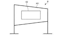
図1は、台形歪み画像の一例を示す図である。
【0027】
例えば、図1に示すように、矩形のスクリーン8の左手前に配置された画像処理システムの一種であるプロジェクタ20が画像補正処理を行わずに矩形の画像を投写した場合、投写領域12は、最左端が最も短く、最右端が最も長い台形状となる。
【0028】
本実施の形態では、投写領域12およびスクリーン領域10を含むセンシング領域14をセンシング手段であるセンサー30を用いて撮像(センシング)する。
【0029】
図2は、プロジェクタ20に搭載されたセンサー30で撮像した画像の一例を示す図である。
【0030】
例えば、プロジェクタ20のレンズの光軸とほぼ同じ光軸でセンサー30が撮像した場合、その撮像画像において、スクリーン領域40における投写領域42は、長方形となり歪んでいないように見える。
【0031】
しかし、図1に示すように、実際には、スクリーン8の正面から見ると、投写領域12は歪んでいる。
【0032】
本実施の形態では、センシング領域14の輝度分布に応じて画像の補正処理を行っている。
【0033】
図3は、画像の明るさの違いを示す模式図である。
【0034】
例えば、図1に示すようにスクリーン8の左手前から単一色の画像を投写した場合、投写領域12の左側が最も輝度が高く、投写領域12の右側が最も輝度が低くなる。
【0035】
本実施の形態では、投写領域12の輝度分布に基づいて画像の歪みを把握し、歪みに応じて画像の補正処理を行っている。これにより、プロジェクタ20のレンズの光軸とほぼ同じ光軸でセンサー30が撮像した場合であっても、画像の歪みを適切に把握することができる。
【0036】
(機能ブロックの説明)
次に、このような機能を実現するためのプロジェクタ20の機能ブロックについて説明する。
【0037】
図4は、本実施形態の一例に係るプロジェクタ20の機能ブロック図である。
【0038】
プロジェクタ20は、信号入力部110と、記憶部120と、歪み補正部130と、信号出力部140と、画像生成部150と、輝度分布解析部160と、周辺情報解析部170と、環境解析部180と、画像投写部190とを含んで構成されている。
【0039】
また、センサー30は、エリアセンサー部182を含んで構成されている。
【0040】
信号入力部110は、PC(Personal Computer)等から入力されるアナログ形式の画像信号を、デジタル形式の画像信号に変換する。
【0041】
また、記憶部120は、投写領域12の座標を導出するための導出用座標を示す座標テーブル122と、投写領域12内における複数の異なる領域ごとの平均輝度の比率と投写領域12の導出用座標とが関連づけられた角度補正テーブル124とを記憶している。なお、ここで、導出用座標としては、例えば、液晶ライトバルブの座標軸における座標、投写画像の座標軸における座標、XYZ3軸の絶対座標における座標等が該当する。
【0042】
ここで、座標テーブル122と角度補正テーブル124のデータ構造およびデータ内容について説明する。
【0043】
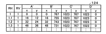
図5は、本実施形態の一例に係る座標データ122のデータ構造を示す図であり、図5(A)は補正前の座標データ122のデータ内容を示す図であり、図5(B)は補正後の座標データ122のデータ内容を示す図である。また、図6は、本実施形態の一例に係る角度補正データ124のデータ構造を示す図である。
【0044】
図5(A)および図5(B)に示すように、座標テーブル122は、投写領域12の4隅ABCDまたはA’B’C’D’の導出用のxy軸における座標を有している。
【0045】
また、図6に示すように、角度補正テーブル124は、投写領域12が横方向に分割された2つの領域の平均輝度の比率RHおよび投写領域12が縦方向に分割された2つの領域の平均輝度の比率RVと、座標テーブル122の導出用座標と対応した導出用座標とが関連づけられている。これにより、プロジェクタ20は、比率RH、RVを求めることにより、導出用座標を一意に求めることができる。
【0046】
また、画像信号の補正を行う画像信号補正手段として機能する歪み補正部130は、信号入力部110から入力される画像信号を1画像分記憶し、座標テーブル122に基づき、投写画像の歪みが補正(リサイズ)されるように画像信号を補正する。
【0047】
なお、歪み補正の具体的な手法としては、例えば、一般的に用いられている遠近変形処理によって歪みを補正する手法を採用してもよい。
【0048】
また、画像生成部150は、全黒画像(黒のみからなる単一色の画像)および全白画像(白のみからなる単一色の画像)等のキャリブレーション画像を投写するための画像信号を生成し、信号出力部140に出力する。
【0049】
このように、キャリブレーション用の画像信号をプロジェクタ20の内部で生成することにより、PC等の外部入力装置からキャリブレーション用の画像信号をプロジェクタ20に入力することなく、プロジェクタ20単体でキャリブレーションを行うことができる。なお、画像生成部150を設けずに、PC等からキャリブレーション用の画像信号を入力してもよい。
【0050】
また、信号出力部140は、歪み補正部130で補正された画像信号や画像生成部150からのキャリブレーション用の画像信号を入力し、アナログ形式の画像信号に変換して画像投写部190に出力する。
【0051】
なお、プロジェクタ20がデジタル形式のRGB信号のみを用いる場合、信号入力部110によるA/D変換処理および信号出力部140によるD/A変換処理は不要である。
【0052】
また、画像投写部190は、空間光変調器192と、空間光変調器192を駆動する駆動部194と、光源196と、レンズ198とを含んで構成されている。
【0053】
駆動部194は、信号出力部140からの画像信号に基づき、空間光変調器192を駆動する。そして、画像投写部190は、光源196からの光を、空間光変調器192およびレンズ198を介して投写する。
【0054】
なお、光源196としては、例えば、点光源、面光源等の種々の光源を採用可能である。
【0055】
また、本実施の形態では、環境解析部180は、エリアセンサー部182からのセンシング情報に基づく輝度情報に基づき、所定の基準よりも明るい明状態か所定の基準よりも暗い暗状態かを判定する。
【0056】
なお、この基準としては、例えば、平均輝度Yを0.3*R信号値+0.6*G信号値+0.1*B信号値によって求めている場合、平均輝度Yが60程度を閾値として明状態か暗状態かを判定してもよい。また、この閾値は、実際にはセンサー30の設定やセンシング領域14によって変化するため、上記値に限定されるものではない。
【0057】
そして、明状態の場合には、周辺情報解析部170が座標テーブル122における導出用座標を更新し、暗状態の場合には、輝度分布解析部160が座標テーブル122における導出用座標を更新する。
【0058】
なお、上述したプロジェクタ20の各部を実現するためのハードウェアとしては、例えば、以下のものを適用できる。
【0059】
図7は、本実施形態の一例に係るプロジェクタ20のハードウェアブロック図である。
【0060】
例えば、信号入力部110としては、例えばA/Dコンバーター930等、記憶部120としては、例えばRAM950等、歪み補正部130、画像生成部150、輝度分布解析部160、周辺情報解析部170および環境解析部180としては、例えば画像処理回路970、RAM950、CPU910等、信号出力部140としては、例えばD/Aコンバーター940等、空間光変調器192としては、例えば液晶パネル920、液晶パネル920を駆動する液晶ライトバルブ駆動ドライバを記憶するROM960等を用いて実現できる。
【0061】
なお、これらの各部はシステムバス980を介して相互に情報をやりとりすることが可能である。
【0062】
また、エリアセンサー部182としては、例えばCCDセンサー等を用いて実現できる。
【0063】
また、これらの各部は回路のようにハードウェア的に実現してもよいし、ドライバのようにソフトウェア的に実現してもよい。
【0064】
さらに、輝度分布解析部160等としてコンピュータを機能させるためのプログラムを記憶した情報記憶媒体900からプログラムを読み取って輝度分布解析部160等の機能をコンピュータに実現させてもよい。
【0065】
このような情報記憶媒体900としては、例えば、CD−ROM、DVD−ROM、ROM、RAM、HDD等を適用でき、そのプログラムの読み取り方式は接触方式であっても、非接触方式であってもよい。
【0066】
また、情報記憶媒体900に代えて、上述した各機能を実現するためのプログラム等を、伝送路を介してホスト装置等からダウンロードすることによって上述した各機能を実現することも可能である。
【0067】
(画像処理の流れの説明)
次に、これらの各部を用いた画像処理の流れについて説明する。
【0068】
図8は、本実施形態の一例に係る画像処理の流れを示すフローチャートである。
【0069】
プロジェクタ20起動後、画像生成部150は、キャリブレーション用の全黒画像と全白画像を投写するための画像信号を生成し、当該画像信号を、信号出力部140を介して画像投写部190に転送する。
【0070】
画像投写部190は、当該画像信号に基づき、全黒画像と全白画像をスクリーン8に投写し、エリアセンサー部182は、それぞれの画像の投写時に、スクリーン領域10および投写領域12を含むセンシング領域14を撮像する(ステップS1)。
【0071】
エリアセンサー部182は、全黒画像と全白画像の撮像情報を環境解析部180に転送する。
【0072】
環境解析部180は、全白画像の撮像情報から全黒画像の撮像情報を引いた差分情報を生成し、当該差分情報に基づき輝度変化量を把握する。そして、環境解析部180は、輝度変化量に基づき、センシング領域14に含まれる投写領域12を識別する。
【0073】
そして、環境解析部180は、投写領域12内の平均輝度と閾値を比較し、所定の状態よりも暗い暗状態であるかどうかを判定する(ステップS2)。
【0074】
環境解析部180は、投写領域12内の平均輝度が閾値未満の暗状態であると判定した場合、全黒画像と全白画像の撮像情報および投写領域12の座標情報を輝度分布解析部160に転送する。
【0075】
輝度分布解析部160は、画像を分割した複数の領域における平均輝度を演算し、各領域の平均輝度を対比した比率を演算する。
【0076】
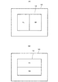
図9は、本実施形態の一例に係る画像を分割した状態を示す模式図であり、図9(A)は、画像を左右に分割した模式図であり、図9(B)は、画像を上下に分割した模式図である。
【0077】
例えば、図9(A)に示すように、投写領域12を左右に分割し、左側の領域の平均輝度をYL、右側の領域の平均輝度をYRとする。また、図9(B)に示すように、投写領域12を上下に分割し、上側の領域の平均輝度をYT、下側の領域の平均輝度をYBとする。
【0078】
輝度分布解析部160は、YRがYL以上の場合、YR/YLを水平方向の比率RHとして求め、YRがYL未満の場合、−(YL/YR)をRHとして求め、YTがYB以上の場合、YT/YBを垂直方向の比率RVとして求め、YTがYB未満の場合、−(YB/YT)をRVとして求める。
【0079】
そして、輝度分布解析部160は、角度補正テーブル124を参照し、RH、RVの値に応じて補正後の導出用座標を示すA’、B’、C’、D’の4点それぞれのxy値を取得する。
【0080】
さらに、輝度分布解析部160は、取得したA’、B’、C’、D’の4点それぞれのxy値を座標テーブル122に書き込んで座標テーブル122を更新する。
【0081】
以上のように、暗状態の場合、輝度分布解析部160が、投写領域12の輝度勾配に基づき、スクリーン8とプロジェクタ20との位置関係を把握し、角度補正テーブル124に基づき、座標テーブル122を補正する(ステップS3)。
【0082】
また、環境解析部180は、投写領域12の平均輝度が閾値以上の明状態であると判定した場合、全黒画像と全白画像の撮像情報および投写領域12の座標情報を周辺情報解析部170に転送する。
【0083】
周辺情報解析部170は、全黒画像の撮像情報に基づく輝度分布に基づき、スクリーン領域10の座標情報を把握する。
【0084】
そして、周辺情報解析部170は、投写領域12の座標情報とスクリーン領域10の座標情報とに基づき、スクリーン領域10が投写領域12に完全に包含されている場合、スクリーン領域10の4隅の座標を用いて座標テーブル122を補正する。
【0085】
また、周辺情報解析部170は、スクリーン領域10が投写領域12に完全に包含されていない場合、図11に示すように、スクリーン領域10の4隅の座標からなる長方形を設定し、当該長方形が投写領域12の内部に完全に包含されるように、当該長方形の縮小処理および平行移動処理を行う。そして、周辺情報解析部170は、当該長方形が投写領域12に完全に包含された時点における4隅の座標を用いて座標テーブル122を補正する。
【0086】
なお、これらの処理によって投写領域12のうち表示されなくなった部分は、スクリーン領域10と同色(例えば黒等)の画像を表示すればよい。
【0087】
以上のように、明状態の場合、周辺情報解析部170が、投写領域12の形状をスクリーン領域10に合わせるように座標テーブル122を補正する(ステップS4)。
【0088】
そして、歪み補正部130は、輝度分布解析部160または周辺情報解析部170によって補正された座標テーブル122に含まれる4隅の座標導出用情報に基づき、画像の歪みを補正するように画像信号を補正する(ステップS5)。
【0089】
そして、画像投写部190は、補正後の画像信号に基づき、画像を投写する(ステップS6)。
【0090】
以上の手順により、プロジェクタ20は、台形歪みが補正された画像を投写する。
【0091】
図10は、本実施形態の一例に係る台形歪み補正後の画像を示す模式図である。
【0092】
例えば、補正前の投写領域12は、四角形ABCDのように台形状であるが、プロジェクタ20は、画像信号を補正することにより、投写領域13のA’B’C’D’のように投写領域を長方形状にすることができる。
【0093】
以上のように、本実施形態によれば、プロジェクタ20は、輝度分布に基づいて投写領域12の歪みを判定している。これにより、プロジェクタ20は、レンズ198とセンサー30の光軸がほぼ同じで撮像画像の形状からは歪みを判別しにくい場合であっても、画像の歪みを適切に判別することができる。これにより、投写画像の歪みを自動的かつ適切に補正することができる。また、投写領域12の厳密な形状を判別する必要はなく、投写領域12の輝度分布を得られればよいため、センサー30として解像度の低いセンサーを適用することも可能である。
【0094】
また、本実施の形態によれば、明状態か暗状態かを判別し、輝度の変化を判別しにくい場合にはスクリーン領域10の各頂点の位置情報を用いて座標データ122における4つの導出用座標を更新することにより、画像の歪みを適切に補正することができる。これにより、種々の使用環境に対してプロジェクタ20を適用することができる。
【0095】
(変形例)
以上、本発明を適用した好適な実施の形態について説明してきたが、本発明の適用は上述した実施例に限定されない。
【0096】
例えば、上述した実施例では、投写領域12の台形歪みについて説明したが、プロジェクタ20は、投写領域12に回転ずれによる歪みが生じている場合であっても画像を補正することが可能である。
【0097】
図12は、本実施形態の一例に係る回転ずれ補正後の画像を示す模式図である。
【0098】
この場合、周辺情報解析部170は、スクリーン領域10の4隅の座標からなる長方形を設定し、当該長方形が投写領域12の内部に完全に包含されるように、当該長方形の縮小処理および平行移動処理を行う。そして、周辺情報解析部170は、当該長方形が投写領域12に完全に包含された時点における4隅の座標を用いて座標テーブル122を補正する。
【0099】
また、プロジェクタ20の内部に傾きセンサーや重力センサーを設け、プロジェクタ20が、縦方向の台形歪みを当該センサーで補正し、横方向の台形歪みをセンサー30によるセンシング情報に基づいて補正してもよい。
【0100】
さらに、レンズ198にズーム機能が設けられている場合、プロジェクタ20は、ズームに関する情報(例えば、最も望遠になった状態が0で最も広角になった状態が1で表される数値等)を取得して台形歪みを補正してもよい。
【0101】
これによれば、望遠機能や広角機能を用いる場合であっても、台形歪みを自動的かつ適切に補正することが可能となる。
【0102】
また、上述した実施例では、図9(A)および図9(B)に示すように、プロジェクタ20は、投写領域12を左右に分割した領域および上下に分割した領域を用いたが、分割数としては、例えば、4、9等の値を用いてもよい。この場合、プロジェクタ20は、分割後の領域ごとに平均輝度を求めて画像処理を行ってもよい。
【0103】
また、角度補正テーブル124は、投写領域12内における複数の異なる領域ごとの平均輝度の比率と投写領域12の導出用座標とが関連づけられたものであるが、平均輝度の比率に代えて平均輝度の差分値を適用してもよい。
【0104】
また、上述した実施例では、キャリブレーション画像は、全白画像および全黒画像であったが、これらの画像に限定されず、種々のキャリブレーション画像を適用可能である。
【0105】
また、上述した実施例では、画像処理システムとしてプロジェクタ20を用いたが、本発明は、プロジェクタ20以外にも種々の前面投写型の画像表示装置に有効である。
【0106】
また、プロジェクタ20としては、例えば、液晶プロジェクタ、DMD(Digital Micromirror Device)を用いたプロジェクタ等を用いてもよい。なお、DMDは米国テキサスインスツルメンツ社の商標である。
【0107】
なお、上述したプロジェクタ20の機能は、例えば、プロジェクタ単体で実現してもよいし、複数の処理装置で分散して(例えば、プロジェクタとPCとで分散処理)実現してもよい。
【0108】
さらに、プロジェクタ20とセンサー30とを別の装置として形成してもよいし、一体の装置として形成してもよい。
【図面の簡単な説明】
【図1】 台形歪み画像の一例を示す図である。
【図2】 プロジェクタに搭載されたセンサーで撮像した画像の一例を示す図である。
【図3】 画像の明るさの違いを示す模式図である。
【図4】 本実施形態の一例に係るプロジェクタの機能ブロック図である。
【図5】 本実施形態の一例に係る座標データのデータ構造を示す図であり、図5(A)は補正前の座標データのデータ内容を示す図であり、図5(B)は補正後の座標データのデータ内容を示す図である。
【図6】 本実施形態の一例に係る角度補正データのデータ構造を示す図である。
【図7】 本実施形態の一例に係るプロジェクタのハードウェアブロック図である。
【図8】 本実施形態の一例に係る画像処理の流れを示すフローチャートである。
【図9】 本実施形態の一例に係る画像を分割した状態を示す模式図であり、図9(A)は、画像を左右に分割した模式図であり、図9(B)は、画像を上下に分割した模式図である。
【図10】 本実施形態の一例に係る台形歪み補正後の画像を示す模式図である。
【図11】 本実施形態の他の一例に係る台形歪み補正後の画像を示す模式図である。
【図12】 本実施形態の一例に係る回転ずれ補正後の画像を示す模式図である。
【符号の説明】
8 スクリーン、 10、40 スクリーン領域、 12、13、42 投写領域、 14 センシング領域、 20 プロジェクタ(画像処理システム)、 30 センサー(センシング手段)、 120 記憶部(記憶手段)、 122 座標テーブル(座標データ)、 124 角度補正テーブル(角度補正データ)、 130 歪み補正部(画像信号補正手段)、 160 輝度分布解析部(輝度分布解析手段)、 170 周辺情報解析部(周辺情報解析手段)、 180 環境解析部(環境解析手段)、 182 エリアセンサー部(センシング手段)、 190 画像投写部(画像投写手段)[0001]
BACKGROUND OF THE INVENTION
The present invention relates to an image processing system, a projector, a program, an information storage medium, and an image processing method capable of correcting distortion of a projected image such as trapezoidal distortion and rotational deviation.
[0002]
[Background]
Various methods for correcting image distortion such as so-called trapezoidal distortion generated in a projected image of a projector have been proposed.
[0003]
For example, there is a method of automatically correcting distortion in the vertical direction by detecting the tilt of the projector.
[0004]
However, this method does not allow the user to correct horizontal distortion.
[0005]
For this reason, there is a technique for manually correcting the distortion in the horizontal direction by pressing the correction switch on the remote controller while the user views the image.
[0006]
However, it is troublesome for the user to manually correct the distortion, and it is difficult to manually correct the distortion appropriately.
[0007]
In view of such a problem, for example, in
[0008]
[Patent Document 1]
JP 2000-241874 A
[0009]
[Problems to be solved by the invention]
However, in this publication, a camera built in the main body is used, and the optical axis of the camera and the optical axis of the lens are almost the same. Therefore, the projection area indicated by the captured image is always substantially rectangular, and based on the captured image. It is difficult to compare the lengths of opposite sides of the projection area.
[0010]
The present invention has been made in view of the above problems, and an object thereof is an image processing system, a projector, a program, an information storage medium, and an image processing method capable of automatically and appropriately correcting distortion of a projected image. Is to provide.
[0011]
[Means for Solving the Problems]
In order to solve the above problems, an image processing system according to the present invention includes a sensing unit that senses a sensing region on which a predetermined projection image is projected and outputs sensing information;
A luminance distribution analyzing means for analyzing the luminance distribution in the projection area included in the sensing area based on the sensing information;
Stores angle correction data in which the ratio of average luminance for each of a plurality of different areas in the projection area and the derivation coordinates for deriving the coordinates of the projection area are associated, and coordinate data indicating the derivation coordinates of the projection area Storage means for
Image signal correction means for correcting the image signal so that distortion of the projected image is corrected based on the coordinate data;
Including
The luminance distribution analyzing means refers to the angle correction data according to the luminance distribution in the projection area, and corrects the derivation coordinates in the coordinate data based on the angle correction data.
[0012]
Further, the projector according to the present invention includes a sensing unit that senses a sensing area where a predetermined projection image is projected and outputs sensing information;
A luminance distribution analyzing means for analyzing the luminance distribution in the projection area included in the sensing area based on the sensing information;
Stores angle correction data in which the ratio of average luminance for each of a plurality of different areas in the projection area and the derivation coordinates for deriving the coordinates of the projection area are associated, and coordinate data indicating the derivation coordinates of the projection area Storage means for
Image signal correction means for correcting the image signal so that distortion of the projected image is corrected based on the coordinate data;
Image projection means for projecting a projected image based on the corrected image signal;
Including
The luminance distribution analyzing means refers to the angle correction data according to the luminance distribution in the projection area, and corrects the derivation coordinates in the coordinate data based on the angle correction data.
[0013]
The program according to the present invention is a computer-readable program,
Computer
Sensing control means for causing the sensing means to sense a sensing area where a predetermined projection image is projected, and outputting sensing information;
A luminance distribution analyzing means for analyzing the luminance distribution in the projection area included in the sensing area based on the sensing information;
The angle correction data in which the ratio of the average luminance for each of a plurality of different areas in the projection area and the derivation coordinates for deriving the coordinates of the projection area are associated, and the coordinate data indicating the derivation coordinates of the projection area are predetermined. Storage control means for storing in the storage area of
Based on the coordinate data, function as image signal correction means for correcting the image signal so that distortion of the projected image is corrected,
The luminance distribution analyzing means refers to the angle correction data according to the luminance distribution in the projection area, and corrects the derivation coordinates in the coordinate data based on the angle correction data.
[0014]
An information storage medium according to the present invention is a computer-readable information storage medium storing the above program.
[0015]
The image processing method according to the present invention senses a sensing area where a predetermined projection image is projected and outputs sensing information.
Based on the sensing information, the brightness distribution in the projection area included in the sensing area is analyzed, and the ratio of the average brightness and the coordinates of the projection area for a plurality of different areas in the projection area are derived according to the brightness distribution in the projection area. Refer to the angle correction data associated with the derivation coordinates for
Based on the angle correction data, correct the derivation coordinates in the coordinate data indicating the derivation coordinates of the projection area,
Based on the coordinate data, the image signal is corrected so that the distortion of the projected image is corrected.
[0016]
According to the present invention, the image processing system or the like determines the distortion of the projection area based on the luminance distribution. As a result, an image processing system or the like appropriately discriminates image distortion even when the optical axis of the projection light and the optical axis of the sensing means are almost the same and it is difficult to discriminate image distortion from the shape of the captured image. can do. Thereby, the image processing system or the like can automatically and appropriately correct the distortion of the projected image.
[0017]
The image processing system and the projector, when projecting a rectangular projection image on a rectangular screen, extract a projection area and a screen area included in the sensing area based on a luminance distribution based on the sensing information. And peripheral information analysis means for updating the four derivation coordinates in the coordinate data based on the extracted position information of each vertex of the projection area and the screen area and the derivation coordinate information of the four corners of the screen area. But you can.
[0018]
The program and the information storage medium extract a projection area and a screen area included in the sensing area based on a luminance distribution based on the sensing information when a rectangular projection image is projected onto a rectangular screen. And a computer as peripheral information analysis means for updating the four derivation coordinates in the coordinate data based on the extracted position information of each vertex of the projection area and the screen area and the derivation coordinate information of the four corners of the screen area. May function.
[0019]
In the image processing method, when a rectangular projection image is projected on a rectangular screen, a projection area and a screen area included in the sensing area are extracted based on a luminance distribution based on the sensing information,
The four derivation coordinates in the coordinate data may be updated based on the extracted position information of each vertex of the projection area and the screen area and the derivation coordinate information of the four corners of the screen area.
[0020]
According to this, the image processing system or the like can appropriately correct the distortion of the image by updating the four derivation coordinates in the coordinate data using the position information of each vertex of the rectangular screen area.
[0021]
Further, the image processing system and the projector include environment analysis means for determining whether the light state is brighter than a predetermined reference or the dark state is darker than a predetermined reference, based on luminance information based on the sensing information,
In the bright state, the peripheral information analysis means may update the derivation coordinates in the coordinate data, and in the dark state, the luminance distribution analysis means may update the derivation coordinates in the coordinate data. .
[0022]
The program and the information storage medium cause the computer to function as an environment analysis unit that determines whether a bright state is brighter than a predetermined reference or a dark state darker than a predetermined reference based on luminance information based on the sensing information. ,
In the bright state, the peripheral information analysis means may update the derivation coordinates in the coordinate data, and in the dark state, the luminance distribution analysis means may update the derivation coordinates in the coordinate data. .
[0023]
In the image processing method, it is determined whether the light state or the dark state based on the luminance information based on the sensing information,
In the bright state, the four derivation coordinates in the coordinate data are updated based on the position information and the derivation coordinate information of the four corners of the screen area. In the dark state, the sensing information is updated. Based on the analysis of the luminance distribution in the projection area, the ratio of the average luminance for each of the different areas in the projection area and the derivation coordinates for deriving the coordinates of the projection area are associated with each other according to the luminance distribution in the projection area. With reference to the angle correction data, the derivation coordinates in the coordinate data indicating the derivation coordinates of the projection area may be corrected based on the angle correction data.
[0024]
According to this, the image processing system or the like can automatically and appropriately correct the distortion of the projected image by correcting the derivation coordinates in the coordinate data by a method suitable for the actual use environment.
[0025]
DETAILED DESCRIPTION OF THE INVENTION
Hereinafter, a case where the present invention is applied to a projector functioning as an image processing system for correcting trapezoidal distortion of a projected image will be described as an example with reference to the drawings. In addition, the embodiment shown below does not limit the content of the invention described in the claim at all. In addition, all of the configurations shown in the following embodiments are not necessarily essential as means for solving the problems described in the claims.
[0026]
(Description of the entire system)
FIG. 1 is a diagram illustrating an example of a trapezoidal distortion image.
[0027]
For example, as shown in FIG. 1, when a
[0028]
In the present embodiment, the
[0029]
FIG. 2 is a diagram illustrating an example of an image captured by the
[0030]
For example, when the
[0031]
However, as shown in FIG. 1, the
[0032]
In the present embodiment, image correction processing is performed according to the luminance distribution of the
[0033]
FIG. 3 is a schematic diagram showing a difference in image brightness.
[0034]
For example, as shown in FIG. 1, when a single color image is projected from the left front side of the screen 8, the left side of the
[0035]
In the present embodiment, image distortion is grasped based on the luminance distribution of the
[0036]
(Description of functional block)
Next, functional blocks of the
[0037]
FIG. 4 is a functional block diagram of the
[0038]
The
[0039]
The
[0040]
The
[0041]
In addition, the
[0042]
Here, the data structures and data contents of the coordinate table 122 and the angle correction table 124 will be described.
[0043]
FIG. 5 is a diagram illustrating a data structure of the coordinate
[0044]
As shown in FIGS. 5A and 5B, the coordinate table 122 has coordinates on the xy axes for deriving the four corners ABCD or A′B′C′D ′ of the
[0045]
As shown in FIG. 6, the angle correction table 124 includes an average luminance ratio RH of two areas obtained by dividing the
[0046]
In addition, the image to correct the image signal signal Functions as a correction means Distortion correction The
[0047]
In addition, Distortion correction As a specific method, for example, a method of correcting distortion by a generally used perspective deformation process may be employed.
[0048]
In addition, the
[0049]
As described above, by generating the calibration image signal inside the
[0050]
In addition, the
[0051]
When the
[0052]
The
[0053]
The driving
[0054]
As the
[0055]
In the present embodiment, the environment analysis unit 180 determines whether the light state is brighter than the predetermined reference or darker than the predetermined reference based on the luminance information based on the sensing information from the
[0056]
As the standard, for example, when the average luminance Y is obtained by 0.3 * R signal value + 0.6 * G signal value + 0.1 * B signal value, the average luminance Y is about 60 as a threshold value. Whether the state is dark or dark may be determined. In addition, the threshold value is not limited to the above value because it actually changes depending on the setting of the
[0057]
Then, in the bright state, the peripheral
[0058]
For example, the following can be applied as hardware for realizing each unit of the
[0059]
FIG. 7 is a hardware block diagram of the
[0060]
For example, as the
[0061]
Note that these units can exchange information with each other via the
[0062]
The
[0063]
Each of these units may be realized by hardware like a circuit, or may be realized by software like a driver.
[0064]
Furthermore, the program may be read from the
[0065]
As such an
[0066]
Further, instead of the
[0067]
(Description of the flow of image processing)
Next, the flow of image processing using these units will be described.
[0068]
FIG. 8 is a flowchart showing a flow of image processing according to an example of the present embodiment.
[0069]
After the
[0070]
The
[0071]
The
[0072]
The environment analysis unit 180 generates difference information obtained by subtracting the imaging information of the all black image from the imaging information of the all white image, and grasps the luminance change amount based on the difference information. Then, the environment analysis unit 180 identifies the
[0073]
Then, the environment analysis unit 180 compares the average brightness in the
[0074]
If the environment analysis unit 180 determines that the average brightness in the
[0075]
The luminance
[0076]
FIG. 9 is a schematic diagram illustrating a state in which an image according to an example of the present embodiment is divided. FIG. 9A is a schematic diagram in which the image is divided into left and right, and FIG. It is the schematic diagram divided | segmented up and down.
[0077]
For example, as shown in FIG. 9A, the
[0078]
The luminance
[0079]
Then, the luminance
[0080]
Further, the luminance
[0081]
As described above, in the dark state, the luminance
[0082]
In addition, when the environment analysis unit 180 determines that the average brightness of the
[0083]
The peripheral
[0084]
Then, the peripheral
[0085]
Further, when the
[0086]
It should be noted that an image of the same color (for example, black) as that of the
[0087]
As described above, in the bright state, the peripheral
[0088]
And Distortion correction Based on the information for deriving the coordinates of the four corners included in the coordinate table 122 corrected by the luminance
[0089]
Then, the
[0090]
Through the above procedure, the
[0091]
FIG. 10 is a schematic diagram showing an image after trapezoidal distortion correction according to an example of the present embodiment.
[0092]
For example, the
[0093]
As described above, according to the present embodiment, the
[0094]
In addition, according to the present embodiment, when it is difficult to discriminate between a bright state and a dark state and it is difficult to discriminate a change in luminance, the position information of each vertex of the
[0095]
(Modification)
The preferred embodiments to which the present invention is applied have been described above, but the application of the present invention is not limited to the above-described examples.
[0096]
For example, in the above-described embodiment, the trapezoidal distortion of the
[0097]
FIG. 12 is a schematic diagram illustrating an image after rotational deviation correction according to an example of the present embodiment.
[0098]
In this case, the peripheral
[0099]
In addition, a tilt sensor or a gravity sensor may be provided inside the
[0100]
Further, when the
[0101]
According to this, even when the telephoto function or the wide-angle function is used, it becomes possible to correct the trapezoidal distortion automatically and appropriately.
[0102]
In the above-described embodiment, as shown in FIGS. 9A and 9B, the
[0103]
The angle correction table 124 associates the average luminance ratio for each of a plurality of different areas in the
[0104]
In the above-described embodiments, the calibration image is an all-white image and an all-black image. However, the calibration image is not limited to these images, and various calibration images can be applied.
[0105]
In the above-described embodiments, the
[0106]
Further, as the
[0107]
Note that the functions of the
[0108]
Furthermore, the
[Brief description of the drawings]
FIG. 1 is a diagram illustrating an example of a trapezoidal distortion image.
FIG. 2 is a diagram illustrating an example of an image captured by a sensor mounted on a projector.
FIG. 3 is a schematic diagram showing a difference in image brightness.
FIG. 4 is a functional block diagram of a projector according to an example of the present embodiment.
5A and 5B are diagrams illustrating a data structure of coordinate data according to an example of the present embodiment. FIG. 5A is a diagram illustrating data contents of coordinate data before correction, and FIG. It is a figure which shows the data content of coordinate data.
FIG. 6 is a diagram illustrating a data structure of angle correction data according to an example of the present embodiment.
FIG. 7 is a hardware block diagram of a projector according to an example of the present embodiment.
FIG. 8 is a flowchart illustrating a flow of image processing according to an example of the present embodiment.
FIG. 9 is a schematic diagram illustrating a state in which an image according to an example of the present embodiment is divided. FIG. 9A is a schematic diagram in which the image is divided into left and right, and FIG. It is the schematic diagram divided | segmented up and down.
FIG. 10 is a schematic diagram illustrating an image after trapezoidal distortion correction according to an example of the present embodiment.
FIG. 11 is a schematic diagram illustrating an image after trapezoidal distortion correction according to another example of the present embodiment.
FIG. 12 is a schematic diagram illustrating an image after rotational deviation correction according to an example of the present embodiment;
[Explanation of symbols]
8 screen, 10, 40 screen area, 12, 13, 42 projection area, 14 sensing area, 20 projector (image processing system), 30 sensor (sensing means), 120 storage section (storage means), 122 coordinate table (coordinate data) ), 124 Angle correction table (angle correction data), 130 Distortion correction Unit (image signal correcting unit), 160 luminance distribution analyzing unit (luminance distribution analyzing unit), 170 peripheral information analyzing unit (peripheral information analyzing unit), 180 environmental analyzing unit (environment analyzing unit), 182 area sensor unit (sensing unit) 190 Image projection unit (image projection means)
Claims (9)
当該センシング情報に基づき、前記センシング領域に含まれる投写領域における輝度分布を解析する輝度分布解析手段と、
投写領域内における複数の異なる領域ごとの平均輝度の比率と投写領域の座標を導出するための導出用座標とが関連づけられた角度補正データと、投写領域の導出用座標を示す座標データとを記憶する記憶手段と、
前記座標データに基づき、投写画像の歪みが補正されるように、画像信号の補正を行う画像信号補正手段と、
を含み、
前記輝度分布解析手段は、投写領域における輝度分布に応じて前記角度補正データを参照し、前記角度補正データに基づき、前記座標データにおける導出用座標を補正することを特徴とする画像処理システム。Sensing means for sensing a sensing area where a predetermined projection image is projected and outputting sensing information;
A luminance distribution analyzing means for analyzing the luminance distribution in the projection area included in the sensing area based on the sensing information;
Stores angle correction data in which the ratio of average luminance for each of a plurality of different areas in the projection area and the derivation coordinates for deriving the coordinates of the projection area are associated, and coordinate data indicating the derivation coordinates of the projection area Storage means for
Image signal correction means for correcting the image signal so that distortion of the projected image is corrected based on the coordinate data;
Including
The image processing system, wherein the luminance distribution analysis unit refers to the angle correction data according to a luminance distribution in a projection area, and corrects the derivation coordinates in the coordinate data based on the angle correction data.
矩形のスクリーンに矩形の投写画像を投写する場合に、前記センシング情報に基づく輝度分布に基づき、投写領域と、前記センシング領域に含まれるスクリーン領域とを抽出するとともに、抽出した投写領域およびスクリーン領域の各頂点の位置情報と、スクリーン領域の4隅の導出用座標情報とに基づき、前記座標データにおける4つの導出用座標を更新する周辺情報解析手段を含むことを特徴とする画像処理システム。In claim 1,
When projecting a rectangular projection image on a rectangular screen, the projection area and the screen area included in the sensing area are extracted based on the luminance distribution based on the sensing information, and the extracted projection area and the screen area An image processing system comprising peripheral information analysis means for updating four derivation coordinates in the coordinate data based on position information of each vertex and derivation coordinate information of four corners of a screen area.
前記センシング情報に基づく輝度情報に基づき、所定の基準よりも明るい明状態か所定の基準よりも暗い暗状態かを判定する環境解析手段を含み、
明状態の場合には、前記周辺情報解析手段が前記座標データにおける導出用座標を更新し、暗状態の場合には、前記輝度分布解析手段が前記座標データにおける導出用座標を更新することを特徴とする画像処理システム。In claim 2,
Based on luminance information based on the sensing information, including environmental analysis means for determining whether the light state is brighter than the predetermined reference or dark state than the predetermined reference;
In the bright state, the peripheral information analysis means updates the derivation coordinates in the coordinate data, and in the dark state, the luminance distribution analysis means updates the derivation coordinates in the coordinate data. Image processing system.
当該センシング情報に基づき、前記センシング領域に含まれる投写領域における輝度分布を解析する輝度分布解析手段と、
投写領域内における複数の異なる領域ごとの平均輝度の比率と投写領域の座標を導出するための導出用座標とが関連づけられた角度補正データと、投写領域の導出用座標を示す座標データとを記憶する記憶手段と、
前記座標データに基づき、投写画像の歪みが補正されるように、画像信号の補正を行う画像信号補正手段と、
補正された画像信号に基づき、投写画像を投写する画像投写手段と、
を含み、
前記輝度分布解析手段は、投写領域における輝度分布に応じて前記角度補正データを参照し、前記角度補正データに基づき、前記座標データにおける導出用座標を補正することを特徴とするプロジェクタ。Sensing means for sensing a sensing area where a predetermined projection image is projected and outputting sensing information;
A luminance distribution analyzing means for analyzing the luminance distribution in the projection area included in the sensing area based on the sensing information;
Stores angle correction data in which the ratio of average luminance for each of a plurality of different areas in the projection area and the derivation coordinates for deriving the coordinates of the projection area are associated, and coordinate data indicating the derivation coordinates of the projection area Storage means for
Image signal correction means for correcting the image signal so that distortion of the projected image is corrected based on the coordinate data;
Image projection means for projecting a projected image based on the corrected image signal;
Including
The brightness distribution analyzing means refers to the angle correction data according to the brightness distribution in the projection area, and corrects the derivation coordinates in the coordinate data based on the angle correction data.
コンピュータを、
所定の投写画像が投写されたセンシング領域をセンシング手段にセンシングさせてセンシング情報を出力するセンシング制御手段と、
当該センシング情報に基づき、前記センシング領域に含まれる投写領域における輝度分布を解析する輝度分布解析手段と、
投写領域内における複数の異なる領域ごとの平均輝度の比率と投写領域の座標を導出するための導出用座標とが関連づけられた角度補正データと、投写領域の導出用座標を示す座標データとを所定の記憶領域に記憶する記憶制御手段と、
前記座標データに基づき、投写画像の歪みが補正されるように、画像信号の補正を行う画像信号補正手段として機能させ、
前記輝度分布解析手段は、投写領域における輝度分布に応じて前記角度補正データを参照し、前記角度補正データに基づき、前記座標データにおける導出用座標を補正することを特徴とするプログラム。A computer-readable program,
Computer
Sensing control means for causing the sensing means to sense a sensing area where a predetermined projection image is projected, and outputting sensing information;
A luminance distribution analyzing means for analyzing the luminance distribution in the projection area included in the sensing area based on the sensing information;
The angle correction data in which the ratio of the average luminance for each of a plurality of different areas in the projection area and the derivation coordinates for deriving the coordinates of the projection area are associated, and the coordinate data indicating the derivation coordinates of the projection area are predetermined. Storage control means for storing in the storage area of
Based on the coordinate data, function as image signal correction means for correcting the image signal so that distortion of the projected image is corrected,
The luminance distribution analysis means refers to the angle correction data according to the luminance distribution in the projection area, and corrects the derivation coordinates in the coordinate data based on the angle correction data.
当該センシング情報に基づき、前記センシング領域に含まれる投写領域における輝度分布を解析し、投写領域における輝度分布に応じ、投写領域内における複数の異なる領域ごとの平均輝度の比率と投写領域の座標を導出するための導出用座標とが関連づけられた角度補正データを参照し、
前記角度補正データに基づき、投写領域の導出用座標を示す座標データにおける導出用座標を補正し、
前記座標データに基づき、投写画像の歪みが補正されるように、画像信号の補正を行うことを特徴とする画像処理方法。Sensing the sensing area where the predetermined projected image is projected and outputting sensing information,
Based on the sensing information, the brightness distribution in the projection area included in the sensing area is analyzed, and the ratio of the average brightness and the coordinates of the projection area for a plurality of different areas in the projection area are derived according to the brightness distribution in the projection area. Refer to the angle correction data associated with the derivation coordinates for
Based on the angle correction data, correct the derivation coordinates in the coordinate data indicating the derivation coordinates of the projection area,
An image processing method, comprising: correcting an image signal based on the coordinate data so that distortion of a projected image is corrected.
矩形のスクリーンに矩形の投写画像を投写する場合に、前記センシング情報に基づく輝度分布に基づき、投写領域と、前記センシング領域に含まれるスクリーン領域とを抽出し、
抽出した投写領域およびスクリーン領域の各頂点の位置情報と、スクリーン領域の4隅の導出用座標情報とに基づき、前記座標データにおける4つの導出用座標を更新することを特徴とする画像処理方法。In claim 7,
When projecting a rectangular projection image on a rectangular screen, based on the luminance distribution based on the sensing information, extract a projection area and a screen area included in the sensing area,
An image processing method comprising: updating four derivation coordinates in the coordinate data based on the extracted position information of each vertex of the projection area and the screen area and the derivation coordinate information of the four corners of the screen area.
前記センシング情報に基づく輝度情報に基づき、明状態か暗状態かを判定し、明状態の場合には、前記位置情報と、スクリーン領域の4隅の導出用座標情報とに基づき、前記座標データにおける4つの導出用座標を更新し、暗状態の場合には、前記センシング情報に基づき、投写領域における輝度分布を解析し、投写領域における輝度分布に応じ、投写領域内における複数の異なる領域ごとの平均輝度の比率と投写領域の座標を導出するための導出用座標とが関連づけられた角度補正データを参照し、前記角度補正データに基づき、投写領域の導出用座標を示す座標データにおける導出用座標を補正することを特徴とする画像処理方法。In claim 8,
Based on the luminance information based on the sensing information, it is determined whether it is a bright state or a dark state, and in the bright state, based on the position information and the coordinate information for derivation of the four corners of the screen area, The four derivation coordinates are updated, and in the dark state, the luminance distribution in the projection area is analyzed based on the sensing information, and an average of a plurality of different areas in the projection area is determined according to the luminance distribution in the projection area. Reference is made to the angle correction data in which the luminance ratio and the derivation coordinates for deriving the coordinates of the projection area are associated, and the derivation coordinates in the coordinate data indicating the projection area derivation coordinates are determined based on the angle correction data. An image processing method characterized by correcting.
Priority Applications (8)
| Application Number | Priority Date | Filing Date | Title |
|---|---|---|---|
| JP2003009690A JP3844075B2 (en) | 2003-01-17 | 2003-01-17 | Image processing system, projector, program, information storage medium, and image processing method |
| US10/757,442 US6932479B2 (en) | 2003-01-17 | 2004-01-15 | Image processing system, projector, program, information storage medium and image processing method |
| KR1020040003185A KR100593113B1 (en) | 2003-01-17 | 2004-01-16 | Image processing system, projector and image processing method |
| CNU2004200011614U CN2686241Y (en) | 2003-01-17 | 2004-01-16 | Image processing system and projector |
| DE602004008975T DE602004008975T2 (en) | 2003-01-17 | 2004-01-16 | Image processing system, projector and image processing method |
| EP04250226A EP1439694B1 (en) | 2003-01-17 | 2004-01-16 | Image processing system, projector and image processing method |
| CNB2004100010527A CN100459676C (en) | 2003-01-17 | 2004-01-16 | Image processing system, projector and image processing method |
| TW093101238A TWI235944B (en) | 2003-01-17 | 2004-01-16 | Image processing system, projector and image processing method |
Applications Claiming Priority (1)
| Application Number | Priority Date | Filing Date | Title |
|---|---|---|---|
| JP2003009690A JP3844075B2 (en) | 2003-01-17 | 2003-01-17 | Image processing system, projector, program, information storage medium, and image processing method |
Publications (3)
| Publication Number | Publication Date |
|---|---|
| JP2004222153A JP2004222153A (en) | 2004-08-05 |
| JP2004222153A5 JP2004222153A5 (en) | 2005-08-11 |
| JP3844075B2 true JP3844075B2 (en) | 2006-11-08 |
Family
ID=32588564
Family Applications (1)
| Application Number | Title | Priority Date | Filing Date |
|---|---|---|---|
| JP2003009690A Expired - Fee Related JP3844075B2 (en) | 2003-01-17 | 2003-01-17 | Image processing system, projector, program, information storage medium, and image processing method |
Country Status (7)
| Country | Link |
|---|---|
| US (1) | US6932479B2 (en) |
| EP (1) | EP1439694B1 (en) |
| JP (1) | JP3844075B2 (en) |
| KR (1) | KR100593113B1 (en) |
| CN (2) | CN2686241Y (en) |
| DE (1) | DE602004008975T2 (en) |
| TW (1) | TWI235944B (en) |
Families Citing this family (37)
| Publication number | Priority date | Publication date | Assignee | Title |
|---|---|---|---|---|
| JP4150924B2 (en) * | 2003-07-02 | 2008-09-17 | セイコーエプソン株式会社 | Image processing system, projector, program, information storage medium, and image processing method |
| JP4260634B2 (en) * | 2002-02-15 | 2009-04-30 | 富士通株式会社 | Image conversion method and apparatus, image recognition apparatus, robot control apparatus, and image projection apparatus |
| JP3541845B1 (en) * | 2003-02-17 | 2004-07-14 | セイコーエプソン株式会社 | Image correction method for projector and projector |
| JP3871061B2 (en) | 2003-03-25 | 2007-01-24 | セイコーエプソン株式会社 | Image processing system, projector, program, information storage medium, and image processing method |
| JP3846592B2 (en) * | 2003-06-26 | 2006-11-15 | セイコーエプソン株式会社 | Image processing system, projector, program, information storage medium, and image processing method |
| JP4055010B2 (en) * | 2003-09-26 | 2008-03-05 | セイコーエプソン株式会社 | Image processing system, projector, program, information storage medium, and image processing method |
| DE10347388A1 (en) * | 2003-10-08 | 2005-05-04 | Zeiss Carl Jena Gmbh | Arrangement for correcting the visual representation of image information |
| WO2006008792A1 (en) * | 2004-07-15 | 2006-01-26 | Sharp Kabushiki Kaisha | Image projecting method, projector and computer program |
| WO2006008791A1 (en) * | 2004-07-15 | 2006-01-26 | Sharp Kabushiki Kaisha | Image projecting method, projector and computer program |
| DE502005010520D1 (en) * | 2004-08-30 | 2010-12-23 | Univ Weimar Bauhaus | METHOD AND DEVICE FOR PRESENTING A DIGITAL IMAGE ON A GEOMETRIC AND PHOTOMETRIC NON-TRIVIAL SURFACE |
| JP4196951B2 (en) * | 2005-02-04 | 2008-12-17 | セイコーエプソン株式会社 | Projector, projected image adjustment method |
| DE102005034990B4 (en) * | 2005-03-21 | 2008-11-20 | Bauhaus Universität Weimar | Method and device for digital projection with high image sharpness |
| US20070024823A1 (en) * | 2005-07-29 | 2007-02-01 | Optoma Technology, Inc. | Methods and systems for improving operation of a video projector |
| US20070025273A1 (en) * | 2005-07-29 | 2007-02-01 | Chung Yau W | Methods and systems for detecting video signals and sources |
| US7434937B2 (en) | 2005-07-29 | 2008-10-14 | Optoma Technology, Inc. | Methods and systems for calibrating rear projection video |
| US8089567B2 (en) | 2005-07-29 | 2012-01-03 | Optoma Technology, Inc. | Methods and systems for displaying video on an adjustable screen |
| US7701518B2 (en) * | 2005-07-29 | 2010-04-20 | Optoma Technology, Inc. | Methods and systems for displaying video in multiple aspect ratios |
| US20070024764A1 (en) * | 2005-07-29 | 2007-02-01 | Optoma Technology, Inc. | Methods and systems that compensate for distortion introduced by anamorphic lenses in a video projector |
| US7357514B2 (en) * | 2005-07-29 | 2008-04-15 | Optoma Technology, Inc. | Methods and systems for improving operation of a video projector |
| US7787062B2 (en) * | 2006-05-19 | 2010-08-31 | Chunghwa Picture Tubes, Ltd. | Rear projection display and circuit and method for adjusting image thereof |
| CN100531318C (en) * | 2006-10-09 | 2009-08-19 | 亚洲光学股份有限公司 | Camera-shooting system and method capable of shooting steadily |
| WO2011002515A1 (en) * | 2009-07-02 | 2011-01-06 | Thomson Licensing | Method and system for differential distortion correction for three-dimensional (3d) projection |
| EP2460362A1 (en) * | 2009-07-29 | 2012-06-06 | Thomson Licensing | Method for crosstalk correction for three-dimensional (3d) projection |
| US9140974B2 (en) * | 2009-08-12 | 2015-09-22 | Thomson Licensing | Method and system for crosstalk and distortion corrections for three-dimensional (3D) projection |
| JP5444947B2 (en) * | 2009-08-26 | 2014-03-19 | 株式会社ニコン | projector |
| DE102009046114B4 (en) * | 2009-10-28 | 2011-09-01 | Fraunhofer-Gesellschaft zur Förderung der angewandten Forschung e.V. | Method and apparatus for generating a calibrated projection |
| CN103020950B (en) * | 2011-09-27 | 2015-09-09 | 华为终端有限公司 | Luminance function acquisition methods and relevant apparatus |
| JP6089424B2 (en) * | 2012-03-21 | 2017-03-08 | セイコーエプソン株式会社 | Image processing apparatus, projector, and projector control method |
| JP5842694B2 (en) | 2012-03-21 | 2016-01-13 | セイコーエプソン株式会社 | Image processing apparatus, projector, and projector control method |
| US9626748B2 (en) * | 2012-07-02 | 2017-04-18 | Seiko Epson Corporation | Projector and method for controlling the same |
| CN103096007B (en) * | 2013-01-07 | 2015-10-21 | 苏州佳世达光电有限公司 | Interactive projection system and bearing calibration thereof |
| JP6056692B2 (en) * | 2013-07-16 | 2017-01-11 | 株式会社デンソー | Inspection device |
| CN105357447B (en) * | 2015-10-30 | 2020-03-13 | 努比亚技术有限公司 | Picture processing method and device |
| CN107422590B (en) * | 2017-09-12 | 2020-09-08 | 中广热点云科技有限公司 | Household projection system capable of automatically adjusting size of projection surface |
| CN109040725B (en) * | 2018-08-31 | 2020-04-14 | 成都极米科技股份有限公司 | Projection angle adjusting method based on use environment of projection device and projection device |
| DE102019100480A1 (en) * | 2019-01-10 | 2020-07-16 | Carl Zeiss Jena Gmbh | Projector for projecting images |
| KR102105801B1 (en) * | 2019-11-13 | 2020-04-29 | 주식회사 애즈원 | Led electronic display system for displaying video on inclined led display panel |
Family Cites Families (14)
| Publication number | Priority date | Publication date | Assignee | Title |
|---|---|---|---|---|
| JP2653899B2 (en) * | 1990-06-07 | 1997-09-17 | 松下電器産業株式会社 | Image correction device |
| JP2861333B2 (en) * | 1990-08-29 | 1999-02-24 | 松下電器産業株式会社 | Image correction device |
| AU1445692A (en) * | 1991-02-14 | 1992-09-15 | Proxima Corporation | Method and apparatus for calibrating geometrically an optical computer input system |
| JP2709423B2 (en) * | 1991-11-13 | 1998-02-04 | 株式会社エイ・ティ・アール通信システム研究所 | Display device |
| DE69422074D1 (en) * | 1993-03-17 | 2000-01-20 | Matsushita Electric Ind Co Ltd | Image correction device |
| JPH07131672A (en) * | 1993-10-28 | 1995-05-19 | Mitsubishi Electric Corp | Wide-aspect ratio television receiver |
| JP3688399B2 (en) * | 1996-07-26 | 2005-08-24 | 株式会社東芝 | Distortion correction circuit |
| EP1118210A4 (en) * | 1998-10-02 | 2006-08-23 | Macronix Int Co Ltd | Method and apparatus for preventing keystone distortion |
| JP2000241874A (en) | 1999-02-19 | 2000-09-08 | Nec Corp | Method and device for automatically adjusting screen position for projector |
| EP1164784A1 (en) * | 2000-06-13 | 2001-12-19 | Koninklijke Philips Electronics N.V. | Preventing doming phenomena |
| JP2002044571A (en) | 2000-07-27 | 2002-02-08 | Nec Viewtechnology Ltd | Projection type grid-shaped display device, and method for correcting distortion of projected video |
| JP2002247614A (en) | 2001-02-15 | 2002-08-30 | Ricoh Co Ltd | Projector |
| WO2002101443A2 (en) | 2001-06-12 | 2002-12-19 | Silicon Optix Inc. | System and method for correcting keystone distortion |
| KR100429874B1 (en) * | 2001-07-20 | 2004-05-04 | 삼성전자주식회사 | Image processing apparatus for realizing panorama/waterglass function and method thereof |
-
2003
- 2003-01-17 JP JP2003009690A patent/JP3844075B2/en not_active Expired - Fee Related
-
2004
- 2004-01-15 US US10/757,442 patent/US6932479B2/en not_active Expired - Fee Related
- 2004-01-16 CN CNU2004200011614U patent/CN2686241Y/en not_active Expired - Fee Related
- 2004-01-16 TW TW093101238A patent/TWI235944B/en not_active IP Right Cessation
- 2004-01-16 CN CNB2004100010527A patent/CN100459676C/en not_active Expired - Fee Related
- 2004-01-16 EP EP04250226A patent/EP1439694B1/en not_active Expired - Fee Related
- 2004-01-16 KR KR1020040003185A patent/KR100593113B1/en not_active IP Right Cessation
- 2004-01-16 DE DE602004008975T patent/DE602004008975T2/en not_active Expired - Lifetime
Also Published As
| Publication number | Publication date |
|---|---|
| KR20040067924A (en) | 2004-07-30 |
| TW200424917A (en) | 2004-11-16 |
| KR100593113B1 (en) | 2006-06-26 |
| EP1439694A1 (en) | 2004-07-21 |
| DE602004008975T2 (en) | 2008-06-19 |
| DE602004008975D1 (en) | 2007-10-31 |
| EP1439694B1 (en) | 2007-09-19 |
| CN100459676C (en) | 2009-02-04 |
| CN1517784A (en) | 2004-08-04 |
| US6932479B2 (en) | 2005-08-23 |
| CN2686241Y (en) | 2005-03-16 |
| US20040201825A1 (en) | 2004-10-14 |
| TWI235944B (en) | 2005-07-11 |
| JP2004222153A (en) | 2004-08-05 |
Similar Documents
| Publication | Publication Date | Title |
|---|---|---|
| JP3844075B2 (en) | Image processing system, projector, program, information storage medium, and image processing method | |
| JP3731663B2 (en) | Image processing system, projector, and image processing method | |
| JP3844076B2 (en) | Image processing system, projector, program, information storage medium, and image processing method | |
| CN103019638B (en) | Display device, projector and display packing | |
| JP4232042B2 (en) | Projection control system, projector, program, information storage medium, and projection control method | |
| JP3871061B2 (en) | Image processing system, projector, program, information storage medium, and image processing method | |
| JP4340923B2 (en) | Projector, program, and information storage medium | |
| JP5257616B2 (en) | Projector, program, information storage medium, and trapezoidal distortion correction method | |
| EP1954061A2 (en) | Image processing system, projector, information storage medium and image processing method | |
| KR101428064B1 (en) | Image distortion compensation apparatus and method | |
| JP2006121240A (en) | Image projection method, projector, and computer program | |
| JP4525945B2 (en) | Image processing system, projector, program, and information storage medium | |
| JP2005124133A (en) | Image processing system, projector, program, information storing medium, and image processing method | |
| JP2007293457A (en) | Image processor | |
| JP3882928B2 (en) | Image processing system, projector, and image processing method | |
| JP2006284639A (en) | Display device | |
| JP3882927B2 (en) | Image processing system, projector, and image processing method | |
| JP2010288062A (en) | Projector, program, information storage medium, and image projection method | |
| JP5093517B2 (en) | Projector, program, information storage medium, and image generation method | |
| JP4511433B2 (en) | Image processing system, projector, portable device, and image processing method | |
| JP5061762B2 (en) | Document camera apparatus, image processing method and program | |
| JP5488584B2 (en) | Image processing apparatus and program | |
| JP2006217370A (en) | Image processing system, projector, program, information storage medium, and image processing method |
Legal Events
| Date | Code | Title | Description |
|---|---|---|---|
| A521 | Written amendment |
Free format text: JAPANESE INTERMEDIATE CODE: A523 Effective date: 20050121 |
|
| A621 | Written request for application examination |
Free format text: JAPANESE INTERMEDIATE CODE: A621 Effective date: 20050121 |
|
| RD04 | Notification of resignation of power of attorney |
Free format text: JAPANESE INTERMEDIATE CODE: A7424 Effective date: 20051221 |
|
| TRDD | Decision of grant or rejection written | ||
| A01 | Written decision to grant a patent or to grant a registration (utility model) |
Free format text: JAPANESE INTERMEDIATE CODE: A01 Effective date: 20060726 |
|
| A61 | First payment of annual fees (during grant procedure) |
Free format text: JAPANESE INTERMEDIATE CODE: A61 Effective date: 20060808 |
|
| R150 | Certificate of patent or registration of utility model |
Free format text: JAPANESE INTERMEDIATE CODE: R150 |
|
| FPAY | Renewal fee payment (event date is renewal date of database) |
Free format text: PAYMENT UNTIL: 20090825 Year of fee payment: 3 |
|
| FPAY | Renewal fee payment (event date is renewal date of database) |
Free format text: PAYMENT UNTIL: 20100825 Year of fee payment: 4 |
|
| FPAY | Renewal fee payment (event date is renewal date of database) |
Free format text: PAYMENT UNTIL: 20110825 Year of fee payment: 5 |
|
| FPAY | Renewal fee payment (event date is renewal date of database) |
Free format text: PAYMENT UNTIL: 20120825 Year of fee payment: 6 |
|
| FPAY | Renewal fee payment (event date is renewal date of database) |
Free format text: PAYMENT UNTIL: 20130825 Year of fee payment: 7 |
|
| S531 | Written request for registration of change of domicile |
Free format text: JAPANESE INTERMEDIATE CODE: R313531 |
|
| R350 | Written notification of registration of transfer |
Free format text: JAPANESE INTERMEDIATE CODE: R350 |
|
| LAPS | Cancellation because of no payment of annual fees |