JP3846083B2 - Inkjet recording device - Google Patents
Inkjet recording device Download PDFInfo
- Publication number
- JP3846083B2 JP3846083B2 JP00819999A JP819999A JP3846083B2 JP 3846083 B2 JP3846083 B2 JP 3846083B2 JP 00819999 A JP00819999 A JP 00819999A JP 819999 A JP819999 A JP 819999A JP 3846083 B2 JP3846083 B2 JP 3846083B2
- Authority
- JP
- Japan
- Prior art keywords
- ink
- flow path
- circulation
- purge
- tank
- Prior art date
- Legal status (The legal status is an assumption and is not a legal conclusion. Google has not performed a legal analysis and makes no representation as to the accuracy of the status listed.)
- Expired - Fee Related
Links
Images


Classifications
-
- B—PERFORMING OPERATIONS; TRANSPORTING
- B41—PRINTING; LINING MACHINES; TYPEWRITERS; STAMPS
- B41J—TYPEWRITERS; SELECTIVE PRINTING MECHANISMS, i.e. MECHANISMS PRINTING OTHERWISE THAN FROM A FORME; CORRECTION OF TYPOGRAPHICAL ERRORS
- B41J2/00—Typewriters or selective printing mechanisms characterised by the printing or marking process for which they are designed
- B41J2/005—Typewriters or selective printing mechanisms characterised by the printing or marking process for which they are designed characterised by bringing liquid or particles selectively into contact with a printing material
- B41J2/01—Ink jet
- B41J2/135—Nozzles
- B41J2/165—Preventing or detecting of nozzle clogging, e.g. cleaning, capping or moistening for nozzles
- B41J2/16517—Cleaning of print head nozzles
- B41J2/1652—Cleaning of print head nozzles by driving a fluid through the nozzles to the outside thereof, e.g. by applying pressure to the inside or vacuum at the outside of the print head
-
- B—PERFORMING OPERATIONS; TRANSPORTING
- B41—PRINTING; LINING MACHINES; TYPEWRITERS; STAMPS
- B41J—TYPEWRITERS; SELECTIVE PRINTING MECHANISMS, i.e. MECHANISMS PRINTING OTHERWISE THAN FROM A FORME; CORRECTION OF TYPOGRAPHICAL ERRORS
- B41J2/00—Typewriters or selective printing mechanisms characterised by the printing or marking process for which they are designed
- B41J2/005—Typewriters or selective printing mechanisms characterised by the printing or marking process for which they are designed characterised by bringing liquid or particles selectively into contact with a printing material
- B41J2/01—Ink jet
- B41J2/17—Ink jet characterised by ink handling
- B41J2/1707—Conditioning of the inside of ink supply circuits, e.g. flushing during start-up or shut-down
-
- B—PERFORMING OPERATIONS; TRANSPORTING
- B41—PRINTING; LINING MACHINES; TYPEWRITERS; STAMPS
- B41J—TYPEWRITERS; SELECTIVE PRINTING MECHANISMS, i.e. MECHANISMS PRINTING OTHERWISE THAN FROM A FORME; CORRECTION OF TYPOGRAPHICAL ERRORS
- B41J2/00—Typewriters or selective printing mechanisms characterised by the printing or marking process for which they are designed
- B41J2/005—Typewriters or selective printing mechanisms characterised by the printing or marking process for which they are designed characterised by bringing liquid or particles selectively into contact with a printing material
- B41J2/01—Ink jet
- B41J2/17—Ink jet characterised by ink handling
- B41J2/18—Ink recirculation systems
-
- B—PERFORMING OPERATIONS; TRANSPORTING
- B41—PRINTING; LINING MACHINES; TYPEWRITERS; STAMPS
- B41J—TYPEWRITERS; SELECTIVE PRINTING MECHANISMS, i.e. MECHANISMS PRINTING OTHERWISE THAN FROM A FORME; CORRECTION OF TYPOGRAPHICAL ERRORS
- B41J2/00—Typewriters or selective printing mechanisms characterised by the printing or marking process for which they are designed
- B41J2/005—Typewriters or selective printing mechanisms characterised by the printing or marking process for which they are designed characterised by bringing liquid or particles selectively into contact with a printing material
- B41J2/01—Ink jet
- B41J2/17—Ink jet characterised by ink handling
- B41J2/19—Ink jet characterised by ink handling for removing air bubbles
-
- B—PERFORMING OPERATIONS; TRANSPORTING
- B41—PRINTING; LINING MACHINES; TYPEWRITERS; STAMPS
- B41J—TYPEWRITERS; SELECTIVE PRINTING MECHANISMS, i.e. MECHANISMS PRINTING OTHERWISE THAN FROM A FORME; CORRECTION OF TYPOGRAPHICAL ERRORS
- B41J2/00—Typewriters or selective printing mechanisms characterised by the printing or marking process for which they are designed
- B41J2/005—Typewriters or selective printing mechanisms characterised by the printing or marking process for which they are designed characterised by bringing liquid or particles selectively into contact with a printing material
- B41J2/01—Ink jet
- B41J2/135—Nozzles
- B41J2/165—Preventing or detecting of nozzle clogging, e.g. cleaning, capping or moistening for nozzles
- B41J2/16517—Cleaning of print head nozzles
- B41J2002/16567—Cleaning of print head nozzles using ultrasonic or vibrating means
Description
【0001】
【発明の属する技術分野】
本発明は、インクを噴射して印字動作を行うインクジェット記録装置に関し、特に、インクタンクと印字ヘッド間のインク流路内の気泡を除くための構造に関する。
【0002】
【従来の技術】
従来より、インクを入力信号にもとづいて噴射し印字動作を行うインクジェット記録装置として、印字ヘッドのアクチュエータにインクを導き、前記入力信号に応じた圧電素子、電歪素子等のアクチュエータの撓みや、発熱素子による局部的なインクの沸騰を利用して、インクを加圧噴射するものが知られている。
【0003】
ところが、印字ヘッドのアクチュエータにインクを導くインク流路内において壁面に何らかの原因で気泡が付着して溜まる場合がある。その気泡がアクチュエータ内に進入すると、アクチュエータ内の圧力を上昇させようとしても、圧力が前記気泡に吸収されてしまい、圧力を十分に高めることができず、インクの噴射がうまく行われない。これは、空気の体積弾性率がインクのそれよりも極端に小さいことによるものであり、印字品質に悪影響を与える。
【0004】
そこで、インク流路の内壁面等に気泡が付着している場合に、簡単な操作でその気泡を取り除き、アクチュエータへの気泡の進入を防止することを目的として、例えば特開昭56−75867号公報に記載されるように、インクタンクと、印字ヘッドのアクチュエータにインクを分配するマニホールドとの間とを、往路お呼び復路からなる循環流路で結び、その循環流路内でインクを強制循環させることでインク流路の壁面に付着している気泡を除く循環パージを行うことが知られている。
【0005】
【発明が解決しようとする課題】
ところで、そのようなものにおいて、循環流路内の壁面などに付着している気泡を効果的に除去するためには、インクの流速を速くすることが望ましいが、インクの流速を速くすると、インク流路内のインク液圧が高まり、その液圧上昇のために印字ヘッドのノズル孔内でインクが表面張力によって形成しているメニスカスを壊し、インクが漏れ出る原因となりやすい。そのため、インクの流速を、気泡を効果的に除去することができる程度まで速くすることができず、インクを循環させるだけで気泡を完全に除去することはできないのが現状である。
【0006】
本発明は、かかる点に鑑みてなされたもので、インク流路に付着している気泡をより効果的に除去することができるインクジェット記録装置を提供することを目的とする。
【0007】
【課題を解決するための手段および発明の効果】
本発明は、インクを噴射して印字動作を行う複数のアクチュエータを有するヘッドユニットと、その複数のアクチュエータに供給するインクを収容し、インクと共に気泡を回収するインクタンクと、印字動作時に前記インクタンクから前記ヘッドユニットへインクを供給する第1のインク流路と、前記インクタンクと前記ヘッドユニットとを接続し前記第1のインク流路と共同してインクの循環流路を形成する第2のインク流路と、前記インクタンク、第1のインク流路、ヘッドユニットおよび第2のインク流路からなる循環流路においてインクを循環させることによりその循環流路内の気泡を前記インクタンクへ回収する循環パージを行うインク循環手段とを備えるインクジェット記録装置において、前記第1のインク流路に前記インク循環手段、前記第2のインク流路に開閉バルブが設けられるとともに、そのインク循環手段および開閉バルブを制御するパージ制御手段が設けられ、印字動作時には、前記インク循環手段が前記第1のインク流路を閉塞しない状態で停止され、前記開閉バルブが閉鎖されて、前記インクタンクから前記第1のインク流路を経て前記ヘッドユニットにインクが供給され、前記循環パージを行う際には、前記パージ制御手段による制御にて前記開閉バルブが開放されかつ前記インク循環手段が駆動され、前記循環流路において第1のインク流路、ヘッドユニット、第2のインク流路およびインクタンクの順にインクが循環され、前記インクタンクへ回収したインクから気泡が分離されて再 び前記第1のインク流路に循環のために供給されるとともに、前記インク循環手段が前記循環流路内の循環パージ中のインクの流れ方向を変更するように制御されることを特徴とする。
【0008】
この発明によれば、循環パージを行う際に、インクの流れ方向を変えることで、インクの流速が大きく変化せしめられ、その流速の大きな変化によってインク流路内の内壁面等に付着している気泡に対し揺さぶりが与えられ、インクの流れによって気泡が除去されやすい状態とされる。特に、第1のインク流路にインク循環手段を設けたことにより、記録動作時にヘッドユニットにインクを供給する側のインク流路内の壁面等に付着している気泡を除去するのに有利であり、インクの流れによって除去された気泡は、インクタンクに回収され、アクチュエータ側に進入することはなくなる。この場合、インクの流れ方向を変えて流速差を大きくして揺さぶりを与えているから、インクの流速を単純に高めて揺さぶりを与える場合に比べて、インク流路内の圧力はそれほど高まらず、そのため印字ヘッドのノズルからインクが漏れ出るという不具合も生じない。
【0009】
上記構成において好ましくは、前記インク循環手段は、第1のインク流路に設けられ正逆回転可能なインク循環用ポンプとし、インク循環用ポンプの回転方向を変更するという簡単な制御でもって、簡単に循環流路内においてインクの流れ方向が変更され、付着している気泡に対し揺さぶりが与えられる。
【0010】
また、上記構成において好ましくは、循環パージを行う際に、通常インクを循環する順方向と逆方向に、その順方向に流す時間よりも短時間だけインクを流した後順方向に流し、付着している気泡に揺さぶりを与えるようにすることで、インクの流れによって除去された気泡が速やかにインクタンクまで運ばれ、インク流路内において、除去された気泡が逆戻りしたり、停滞したりすることがなくなる。
また、上記構成において好ましくは、前記インク循環用ポンプは、前記第1のインク流路を構成するチューブをその長手方向に順次押しつぶすことによりインクを流動させる形式のものである。また、前記ヘッドユニットのインク噴射口が開口するノズル面を開閉可能に覆う吸引キャップと、その吸引キャップに接続された吸引ポンプとを備える吸引パージ装置がさらに備えられ、その吸引パージ装置には前記パージ制御手段が連係されている。さらに、前記ヘッドユニットは、前記複数のアクチュエータを有する印字ヘッドと、その全アクチュエータにわたって設けたインク溜まり、そのインク溜まりの両端に連通したインク流入部およびインク流出部を有するマニホールドとを備え、前記第1のインク流路および第2のインク流路は、前記インク流入部およびインク流出部に接続されている。
【0011】
【0012】
【0013】
【0014】
【0015】
【0016】
【0017】
【0018】
【0019】
【0020】
【0021】
【0022】
【0023】
【0024】
【0025】
【0026】
【0027】
【0028】
【0029】
【0030】
【0031】
【0032】
【0033】
【0034】
【0035】
【0036】
【発明の実施の形態】
以下、本発明の実施の形態を図面に沿って説明する。
【0037】
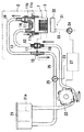
図1は第1の実施の形態のインクジェット記録装置の概略構成を示す。図1に示すように、印字ヘッド1を備えるヘッドユニット2がキャリッジ3に搭載されている。そして、前記印字ヘッド1およびキャリッジ3の動作は、図示しないマイクロコンピュータによって制御され、印字動作時には、印字媒体(図示せず)に対し印字を行う印字エリアにおいてキャリッジ3が往復移動すると共に、印字ヘッド1は、印字データに基づいて複数のアクチュエータが選択的に駆動され、インクが噴射されて印字が行われる一方、印字休止時には、キャリッジ3が印字エリア外の回復エリア内に移動するようになっている。印字ヘッド1は、通常の印字ヘッドと同様に、後述するマニホールド11からインクが供給される複数の圧力室を備え、その圧力室内のインクにアクチュエータにより噴射エネルギーを与えるものである。アクチュエータは、公知のように、圧電素子、電歪素子等の撓みや、発熱素子による局部的なインクの沸騰を利用して、インクを加圧噴射するものが用いられる。各圧力室の噴射口即ちノズル孔は、印字ヘッド1の下面(ノズル面)に開口している。
【0038】
前記ヘッドユニット2は、印字ヘッド1の上面に接着されたマニホールド11と、該マニホールド11のインク流入口部11aに一端部が接続され他端部にジョイント部材12が設けられた第1のヘッド側インクチューブ13と、前記マニホールド11のインク流出口部11bに一端部が接続され他端部にジョイント部材15が設けられた第2のヘッド側インクチューブ16とを備える。マニホールド11のインク流入口部11aとインク流出口部11bは、印字ヘッド1の全アクチュエータの圧力室にわたって設けたインク溜まり部11cの両端に連通されている。なお、前記インク流出口部11bおよびジョイント部材12には、インク中のゴミを捕捉するフィルタ部材14、17が設けられている。
【0039】
一方、前記キャリッジ3には、ヘッドユニット2が搭載された状態で、前記ジョイント部材12に着脱可能に連結されるジョイント受け部材18が設けられている。
【0040】
ジョイント受け部材18には、第1のタンク側インクチューブ23の一端部が接続され、そのチューブ23の他端はインクタンク21に接続されている。チューブ23の途中には正逆回転可能なインク循環用ポンプ22が設けられている。ジョイント部材15には、第2のタンク側インクチューブ26の一端部が接続され、そのチューブ26の他端はインクタンク21に接続されている。チューブ26の途中に開閉バルブ25が設けられている。
【0041】
インク循環用ポンプ22は、図示のものではチューブ23を可撓性のもので構成し、複数のローラ等の押圧部材でそのチューブの一部をチューブの長手方向に順次押しつぶすことで、インクを流動させる形式のものであるが、このほか公知の種々の形式のものが用いられる。開閉バルブ25は、電磁石、モータ等によって動作されもので、通常の印字が行われるときには閉じられ、循環ポンプ22が駆動されるときには開かれる。
【0042】
両タンク側チューブ23、26は、インクタンク21の底部両端に相互に離れて開口している。その両チューブ23、26の開口部の間においてインクタンク21内には、複数の仕切21aが設けられ、第2のタンク側チューブ26からインクタンク21内に入ったインクは、仕切21aを迂回しながら蛇行して第1のタンク側チューブ23へ流れる際に、インク中に含まれる気泡を浮力により分離するようになっている。インクタンク21は上面を大気に開口しており、分離した気泡を放出することができる。
【0043】
また、印字エリアの側方の回復エリアには、印字ヘッド1内のインクを吸引する吸引パージ装置31が設けられている。吸引パージ装置31は、印字ヘッド1のノズル面を覆う吸引キャップ32と、該吸引キャップ32に吸引パイプ33を通じて接続される吸引用ポンプ34と、吸引キャップ32を印字ヘッド1のノズル面に対して接近および離隔する方向に移動する公知の移動手段(図示せず)とを備え、公知のように吸引キャップ32で印字ヘッドのノズル面を覆い、インクを吸引してパージを行うものである。
【0044】
前記インク循環用ポンプ22、開閉バルブ25及び吸引パージ装置31には、マイクロコンピュータからなるパージ制御手段27が連係され、該パージ制御手段27にて、インク循環用ポンプ22、開閉バルブ25及び吸引パージ装置31の制御が行われ、インク内に溜まった気泡を除去し印字ヘッド1の良好なインク噴射状態を確保するようになっている。
【0045】
上記のように構成すれば、印字ヘッド1にインクを充填する際、パージ制御手段27による制御にて、吸引キャップ32が移動手段(図示せず)により前進せしめられて印字ヘッド1のノズル面を覆い、また開閉バルブ25が開放されるととともに、インク循環用ポンプ22が回転駆動される。これにより、インクは、インクタンク21から、第1のタンク側インクチューブ23、第1のヘッド側インクチューブ13を経て、マニホールド11のインク溜まり部11cに供給され、第2のヘッド側インクチューブ16及び第2のタンク側インクチューブ26を経て、前記インクタンク21に戻される。その後、開閉バルブ25が閉鎖されるともとに、インク循環用ポンプ22が第1のタンク側インクチューブ23を閉塞しない状態で停止される。そして、吸引用ポンプ34が駆動されることにより、インク溜まり部11c内のインクが吸引キャップ32を通して吸引され、印字ヘッドの各圧力室にインクが充填される。印字動作時には、印字ヘッド1でのインク噴射による圧力低下により、インクがインクタンク21から、第1のタンク側インクチューブ23、第1のヘッド側インクチューブ13を経て供給される。
【0046】
インクタンク21、第1のタンク側インクチューブ23、第1のヘッド側インクチューブ13、マニホールド11のインク溜まり部11c、第2のヘッド側インクチューブ16、第2のタンク側インクチューブ26、インクタンク21からなる循環流路の壁面等に付着した気泡は、その循環流路に強制的にインクを流動させることにより、除去される。
【0047】
すなわち、循環パージが行われる際には、パージ制御手段27による制御にて、インク循環用ポンプ22が駆動されるとともに開閉バルブ25が開放され、インクタンク21から、第1のインク流路を構成する第1のタンク側インクチューブ23および第1のヘッド側インクチューブ13を通じてマニホールド11のインク溜まり部11cにインクが供給され、該インク溜まり部11cから、第2のインク流路を構成する第2のヘッド側インクチューブ16および第2のタンク側インクチューブ26を通じて、インクタンク21に回収される。回収されたインクがインクタンク21内の仕切21aを蛇行する間に、インク中に含まれる気泡が浮上して大気に放出される。そして、気泡の少ないインクが、第1のタンク側インクチューブ23を通じて印字ヘッド1に供給されるように構成されている。
【0048】
その循環パージを行う際に、インク循環用ポンプ22の回転方向が短時間だけ変更され、そのインクの流れ方向の変更によって、インクチューブ23,13,16,26内の壁面等に付着している気泡に揺さぶりが与えられ、インクの流れによって気泡が除去されやすい状態とされる。そのようなインクの流れ方向の制御は、パージ制御手段27にてインク循環用ポンプ22の回転方向を制御することで行われるが、その制御の態様としては、例えば、インク循環用ポンプ22(毎分20回転程度)を、通常インクが流れる順方向にインクが流れるように20回転させ、その20回転後に逆方向に1回転させ、それから、再び順方向に20回転させるということが繰り返し行われる。
【0049】
このように、通常インクを流す順方向と逆方向にインクを流すことにより、前記循環流路内のインクの流速に変化を生ぜしめ、インクの流速が大きく変化することで、インク流路を形成するインクチューブ13,16,23,26の内壁面に付着している気泡に対し揺さぶりが与えられ、それらの気泡が除去されやすい状態とされる。また、インクを逆方向に流すのは、短時間だけであるので、インクの流れによって除去された気泡が、インク流路内において、逆戻りしたり、停滞したりすることがなく、速やかに第2のインク流路16、26を通じてインクタンク21まで運ばれる。
【0050】
特に、第1のタンク側インクチューブ23に設けたインク循環用ポンプ22を利用して、インクを流す方向を変更するようにしているので、それに近い第1のタンク側インクチューブ23及びそれに連続する第1のヘッド側インクチューブ13側において壁面等に付着している気泡は効果的に揺すぶられ、除去されやすい状態とされる。すなわち、このように、インク循環用ポンプ22を利用することで、印字ヘッド1にインクを供給する側のインクチューブ23,13内の壁面等に付着している気泡を除去するのが有利となる。
【0051】
また、インクの流れ方向を変化させて、インクの流速を大きく変化させるようにしているので、インク流路(インクチューブ13,16,23,26)内の圧力をそれほど高めることもない。よって、印字ヘッド1のノズル孔に形成されているインクのメニスカスを破壊し、インクが漏れ出るということもない。
【0052】
吸引パージ手段31は、公知のように印字ヘッド1のノズル面に吸引キャップ32を密着させて印字ヘッドの圧力室からインクを吸引することで、圧力室内の気泡を除去するものであるが、この動作は、前述の循環パージと独立に行ってもよいく、また、後述する参考例のように循環パージと関連して行ってもよい。
【0053】
図2と図3は、第1の参考例の構成を示すものである。前記実施の形態と同一部分には同一の符号を付してその説明を省略する。
【0054】
本参考例では、循環されるインクに振動を付与する振動付与手段41が設けられる。振動付与手段41は、インク循環用ポンプ22の下流側に設けられ、例えば図3に示すように、インクチューブ23に当接する当接部42aを有する動作部材すなわちカム部材42を用い、該カム部材42に一体的に設けられたギヤ部(図示せず)に噛み合うピニオン部材43と、該ピニオン部材43を回転駆動する駆動手段としてのステップモータ44とにより構成される。第1のタンク側インクチューブ23は、カム部材42との間欠的な接触で振動しやすいように、可撓性材料にてフレキシブルに形成されている。
【0055】
振動付与手段41は、循環パージを行う際(たとえば1分間程度行われる)に、循環パージ開始後に、パージ制御手段41による制御にてステップモータ44が駆動されることで、カム部材42が1〜2回転され、当接部42aがインクチューブ23を間欠的に弾いて振動を与え、循環しているインクに振動(揺さぶり)を付与するようになっている。
【0056】
循環パージは、前述の実施の形態と同様にインク循環ポンプ22を駆動し、開閉バルブ25を開放した状態で、インクタンク21、第1のタンク側インクチューブ23、第1のヘッド側インクチューブ13、マニホールド11のインク溜まり部11c、第2のヘッド側インクチューブ16、第2のタンク側インクチューブ26、インクタンク21からなる循環流路にインクを強制循環させて行う。その循環パージを行う際に、インク循環用ポンプ22の下流側でカム部材42が間欠的にフレキシブルなインクチューブ23に接触し、インクチューブ23を振動させ、インクチューブ23内の壁面等に付着している気泡に揺さぶりが与えられ、インクの流れによって気泡が除去されやすい状態とされる。そして、インクの流れによって除去された気泡は、インクの流れと共にインクタンク21に回収され、分離される。
【0057】
特に、第1のタンク側インクチューブ23に振動を付与するようにしているので、印字ヘッド1へのインク供給側となる、第1のタンク側インクチューブ23およびそれに連続する第1のヘッド側インクチューブ13側において壁面等に付着している気泡が効果的に揺すぶられ、除去されやすい状態とされる。すなわち、このように、インク循環用ポンプ22の下流側において振動を付与することで、印字ヘッド1にインクを供給する側のインクチューブ23,13内の壁面等に付着している気泡を効果的に除去し、戻り側のインクチューブ16,26を通してその気泡を回収することができる。その結果、印字動作中に、印字ヘッド1に供給するインク内の気泡をきわめて少なくすることができ、気泡による印字不能をなくすことができる。
【0058】
また、循環するインクに振動を付与することで、付着している気泡に揺さぶりを与えるようにしているので、インク流路(インクチューブ13,16,23,26)内の圧力をそれほど高めることもない。よって、印字ヘッド1のノズル孔に形成しているメニスカスを破壊し、インクが漏れ出るということもない。
【0059】
なお、前記参考例においては、振動付与手段41として、カム部材42をステップモータ44にて回転駆動することで振動を付与するようにしたものを用いているが、そのほか、例えば、カム部材を一定角度範囲において揺動させるようにすることもできる。このようにすれば、回転させる場合に比べて、必要スペースが少なくなり、省スペースを図る上で有利となる。また、カム部材を設けることなく、キャリッジに当接部を設け、キャリッジを移動させることで当接部にてインクチューブを弾き、振動を付与するようにすることも可能であるし、また、市販の各種のバイブレータを使用することもできる。
第2の参考例の構成は、パージ制御手段27により循環パージの実行とともに吸引パージも実行するもので、図示すると図1と同様になる。
【0060】
印字休止時において、キャリッジ3が印字エリアから回復エリアに移動した状態で、循環パージが行われる際には、前述の実施の形態と同様に、パージ制御手段27による制御にて、開閉バルブ25が開放されると共に、インク循環用ポンプ22が回転駆動され、インクタンク21から、第1のタンク側インクチューブ23、第1のヘッド側インクチューブ13、マニホールド11のインク溜まり部11c、第2のヘッド側インクチューブ16及び第2のタンク側インクチューブ26を経て、前記インクタンク21にインクが戻るようにインクが強制的に流される。そしてチューブ内壁面に付着している気泡はインクの流れとともにインクタンク21に運ばれ分離される。
【0061】
それに加えて、その循環パージを行う際に、パージ制御手段27による制御にて、循環パージの最初から一定時間だけ、吸引パージ装置31が駆動せしめられて、前記循環パージに併せて吸引パージを行うようになる。すなわち、循環パージが開始されると同時に、吸引キャップ32が図示しない移動手段により前進せしめられて印字ヘッド1のノズル面を覆い、その状態で、吸引用ポンプ34が駆動されて、吸引キャップ32を通じて印字ヘッド1内の気泡をインクとともに吸引する吸引パージが行われ、それから、一定時間経過後、吸引ポンプ34の駆動が停止され、吸引キャップ32が後退せしめられる。
このようにパージ制御手段27による制御により、循環パージの最初から一定時間だけ、吸引パージが併用されるので、循環流路内だけでなく、印字ヘッドの圧力室の気泡が除去される。また、循環パージと吸引パージとの相乗効果により、第1のタンク側インクチューブ23、第1のヘッド側インクチューブ13内の流速が高められる。そのようにインクの流速が速まることで、インクチューブ13、23の内壁面に付着している気泡が除去されやすくなる。なお、キャリッジ3が印字エリアに戻る際には、インクの噴射不良回復のための通常の吸引パージが終了した場合と同様に、ワイパー部材(図示せず)にて印字ヘッド1のノズル面がワイピングされ、印字ヘッド1の各ノズル内でインクのメニスカスが形成される。
【0062】
よって、第1のヘッド側インクチューブ13及び第1のタンク側インクチューブ23側において付着している気泡が印字ヘッド1に供給されるという事態が回避され、良好な印字状態が確保される。
【0063】
また、循環パージの際に行う吸引パージ装置31による吸引パージは、循環パージの最初から一定時間だけ行われるだけであり、通常の吸引パージの場合よりも吸引されるインク量は少ないので、循環パージに吸引パージを併用することでインクが無駄に消費されるということもない。さらに、最初の部分において前述のように流速が速められることで、早期に気泡が除去されやすくなり、全体の気泡除去が短時間に行われる。
【0064】
また、本第2の参考例においては、循環パージに併用する吸引パージ手段としては、通常の吸引パージを行う吸引パージ手段を利用しているが、本参考例はそれに限定されるものではなく、循環パージを行う際の吸引パージのみを行う専用の吸引パージ手段を、前記通常の吸引パージ手段とは別に設けることもできる。
【0065】
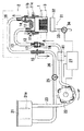
図4は、第3の参考例の構成を示すものである。本参考例は、印字ヘッドのノズル面と吸引キャップとの間に閉空間を形成することによって、循環パージを行う際のインクの流速を速くすることができるようにしている。
【0066】
具体的には、吸引パージ手段31のパイプ33に開閉手段たとえばバルブ35が設けられ、その吸引パージ装置31および開閉手段35は、インク循環ポンプ22および開閉バルブ25とともに、パージ制御手段27に連係されている。パージ制御手段27は、インクの噴射不良の場合に行われる通常のパージ動作のほか、循環流路内の気泡を除く循環パージを行う際に、吸引キャップ32が印字ヘッドのノズル面を覆うとき開閉手段35が閉じて、吸引キャップ32とノズル面との間に閉空間を形成するようになっている。
【0067】
前述の実施の形態のように印字ヘッド1にインクを充填する際、および印字ヘッドの圧力室内のインクを吸引する際には、吸引用ポンプ34の駆動を有効にするために、パージ制御手段27による制御にて、開閉手段35は開放される。
【0068】
インクチューブ23,13,16,26(特にインク供給側となるインクチューブ23,13)内の壁面等に付着している気泡を除くために、循環パージが行われる際には、まず、キャリッジ3が印字エリアから回復エリアに移動して印字休止状態とされる。それから、パージ制御手段27による制御にて、インク循環用ポンプ22が駆動されると共に開閉バルブ25が開放され、インクタンク21から、第1のタンク側インクチューブ23、第1のヘッド側インクチューブ13、マニホールド11のインク溜まり部11c、第2のヘッド側インクチューブ16及び第2のタンク側インクチューブ26を経て、前記インクタンク21にインクが戻るようにインクが強制的に流され、チューブ内壁面に付着している気泡はインクとともにインクタンク21に運ばれ、除去される。
【0069】
それに加えて、循環パージを行う際に、パージ制御手段27による制御にて、吸引パージ装置31の吸引キャップ32で印字ヘッド1のノズル面を覆うとともに開閉手段35が閉じられ、ノズル面と吸引キャップ23との間の空間が密閉空間とされる。開閉手段35が閉じられるのは、キャップ23が前進する際その内の空気が印字ヘッドのノズル内に押し込められないように、密閉空間を形成するのと同時またはその直後であることが望ましい。これにより、循環流路内のインクの流速を、インクチューブ13,16,23,26の内壁面に付着している気泡が除去されやすくなる程度に高めても、上記密閉空間内の空気がその圧力に対抗するので、ノズル内のインクのメニスカスが破壊されることがなく、インクが漏れ出るおそれがない。特に、吸引キャップ23は公知のようにゴム等の弾性材料で製作されているから、ノズル面に少し強く当てることで圧縮され、それにともない上記密閉空間も圧力がわずか上昇して、循環流路内のインクの流速を一層高めてもインクのメニスカスを破壊することがなくなる。
【0070】
キャリッジ3が循環パージ後に印字エリアに戻る際には、インクの噴射不良回復のための通常の吸引パージの場合とは異なり、ワイパー部材(図示せず)にて印字ヘッド1のノズル面をワイピングすることを省略することもできる。
【0071】
よって、第1のヘッド側インクチューブ13及び第1のタンク側インクチューブ23側において付着している気泡が印字ヘッド1に供給されるという事態が回避され、良好な印字状態が確保される。
【0072】
また、循環パージを行う際に、吸引パージ装置31による吸引パージを行うのではなく、吸引キャップ32にて印字ヘッド1のノズル面を覆っているだけであるので、気泡を除くためにインクが無駄に消費されるということもない。
【0073】
第4の参考例の構成は、上記の密閉空間を形成するのに保存キャップを利用する。図示しないが図4において吸引ポンプ34、開閉手段35、パイプ33を省略し、吸引キャップ32を保存キャップに置き換えたものである。保存キャップは、公知のように印字ヘッドのノズル面に密着してノズル孔内のインクが乾燥するのを防止するもので、空気の漏れがなく、上記密閉空間を形成するには好適な部品である。循環パージにおいて、第3の参考例とは開閉手段35の制御がなくなるだけで、実質的に同様の作用を奏する。
【0074】
第5の参考例の構成は、循環流路内の圧力を高め第1のインク流路の壁面や印字ヘッドの圧力室等に付着している気泡をインクの流れによって印字ヘッドのノズル孔から外部に押し出すものである。図示すると図1と同様になる。
【0075】
本第5の参考例の吸引パージ装置31は、パージ制御手段27に連係され、インクの噴射不良の場合に行われる吸引パージ動作のほか、後述する補助パージにおいて印字ヘッド1のノズル孔から押し出されたインクを受け、排出する機能も行う。
【0076】
すなわち、前述の実施の形態および参考例の循環パージを行う前段階又は前記循環パージが終了した後段階において、開閉バルブ25を閉じた状態で、インク循環用ポンプ22を駆動する補助パージを行うことで、インクチューブ23,13内の圧力を高め、インク流路の壁面等に付着している気泡が除去されやすくし、その除去された気泡が印字ヘッド1のノズル孔を通じて外部に押し出されるようにしている。その際、そのインクによる周囲の汚損を防止するために、吸引パージ装置31を駆動して、押し出されるインクを吸引キャップ32で受けるようになっている。この場合、吸引キャップ32は、印字ヘッドのノズル面に密着している必要はなく、対向しているだけでもよい。
【0077】
印字ヘッド1にインクを充填する動作、および印字ヘッドの圧力室内のインクを吸引する吸引パージは、実施の形態と同様に行われる。
【0078】
印字休止時において、循環パージが行われる際には、キャリッジ3が印字エリアから回復エリアに移動した状態で、実施の形態と同様に循環流路においてインクが強制的に流され、その循環路中の気泡はインクとともにインクタンク21に運ばれ、除去される。
【0079】
それに加えて、循環パージを行う前段階又は循環パージが終了した後段階に、開閉バルブ25にて第2のインクチューブ26の連通が遮断され、その状態で、循環ポンプ22が一定時間だけ駆動される補助パージが行われる。この補助パージによって、第1のヘッド側インクチューブ13および第1のタンク側インクチューブ23のインク流路内の圧力が高められ、インク流路の壁面等に付着している気泡が、循環パージを行うよりもさらに除去されやすくなる。その結果、インク流路の壁面および圧力室内の気泡は、インクとともに印字ヘッド1のノズル孔から外部に押し出される。このとき、印字ヘッド1のノズル面は、吸引キャップ32にて覆われており、押し出されたインクは、吸引キャップ32からパイプ33を経て排出される。このとき、吸引キャップ32からインク排出のために吸引ポンプ34を駆動する。
【0080】
これによって、循環パージと補助パージとの相乗効果により、第1のタンク側インクチューブ23、第1のヘッド側インクチューブ13の内壁面やマニホールド11のインク溜まり部11c、印字ヘッドの圧力室に付着している気泡が効果的に除去され、気泡が印字ヘッド1の圧力室を閉塞したり、アクチュエータによる圧力を吸収してしまうという事態が回避され、良好な印字状態が確保される。
【0081】
なお、循環パージを行う前段階又は循環パージが終了した後段階における補助パージを繰り返すこともできる。すなわち、循環パージが終了した後段階において補助パージを行い、それから再度循環パージを行うようにすることもできる。
【0082】
前記第5の参考例においては、循環パージを行う前段階又は前記循環パージが終了した後段階において、補助パージを行う際に、開閉バルブにて第2のインク流路の連通を遮断して、前記循環ポンプを一定時間だけ駆動するようにしているが、第6の参考例の構成はそれに限定されるものではなく、インク流路内の圧力を高めれば、壁面等の付着している気泡が離れやすくなることから、例えば開閉バルブに代えて、絞り部を有する弁回路を用い、補助パージを行う際に、第2のインク流路におけるインクの流れを絞り、第2のインク流路の流れを抑制することでインク流路内の圧力を高めるようにすることもできる。なお、この場合においても、弁回路は、印字動作を行う際には、第2のインク流路の連通を遮断して、印字動作を阻害しないようにする必要がある。
【0083】
本第6の参考例においては、キャッピング手段として、通常の吸引パージを行う吸引パージ手段を利用しているが、それに限定されるものではない。すなわち、積極的の吸引を行わせなくても、少なくとも押し出されたインクを周囲を汚染することなく処理できればよいので、補助パージを行う際に印字ヘッドのノズル面をキャップにて覆う専用のキャッピング手段を、前記通常の吸引パージ手段とは別に設けることもできる。そのほか、印字停止時又は印字休止時に印字ヘッドのノズル面を覆いノズル面の乾燥を防止する保存キャップを有する保存キャップ手段を利用することもできる。それらの場合であっても、キャップ内のインクを排出するポンプを設け、循環ポンプを一定時間だけ駆動した後、漏れ出たインクを排出するために、前記ポンプの駆動して、キャップを利用してインクを排出させるようにすることも可能である。また、ノズルから押し出されたインクを多孔質材、容器等に直接受けるようにしても差し支えない。
【0084】
なお、前記実施の形態および参考例においては、キャリッジを、印字エリアにおいて印字媒体に沿って往復移動させながら印字媒体に印字を行うインクジェット記録装置に適用したものについて説明したが、キャリッジが媒体に沿って移動しないものにも適用することができる。
【0085】
また、インクタンク21には、そのインクタンク内のインクの減少にともなってインクを補給する大容量のメインタンクを接続するようにしてもよい。
【0086】
各実施の形態および参考例は、それぞれ単独に実施するだけでなく、任意に組み合わせて実施するすることができる。
【0087】
以上のように本発明の実施の形態によれば、循環パージを行う際に、インクの流れ方向を変えることで、インクの流速が大きく変化せしめられ、その流速の大きな変化によってインク流路内の内壁面等に付着している気泡に対し揺さぶりが与えられ、インクの流れによって気泡が除去されやすい状態とされる。インクの流れによって除去された気泡は、インクタンクに回収され、アクチュエータ側に進入することはなくなる。この場合、インクの流れ方向を変えて流速差を大きくして揺さぶりを与えているから、インクの流速を単純に高めて揺さぶりを与える場合に比べて、インク流路内の圧力はそれほど高まらず、そのため印字ヘッドのノズルからインクが漏れ出るという不具合も生じない。
【0088】
また、インク循環手段は、正逆回転可能なインク循環用ポンプとし、回転方向を変更するという簡単な制御でもって、循環流路内においてインクの流れ方向が変更され、付着している気泡に対し揺さぶりが与えられる。
【0089】
また、循環パージを行う際に、通常インクを循環する順方向に流す時間よりも短時間だけ、その順方向と逆方向にインクを流すことで、付着している気泡に揺さぶりを与え、除去された気泡がインクの流れによって速やかにインクタンクまで運ばれ、インク流路内において、除去された気泡が逆戻りしたり、停滞したりすることがなくなる。
【0090】
なお第1の参考例として示す構成は、循環パージを行う際に、振動付与手段にて、循環されるインクに振動が付与され、その振動によって、インクを介してインク流路内の内壁面等に付着している気泡に対し揺さぶり(衝撃を含む)が与えられ、循環パージによるインクの流れによって気泡が除去されやすい状態とされる。よって、気泡はインクの流れによって除去されて、インクタンクに回収され、印字ヘッド側に気泡が進入することはなくなる。この場合、循環されるインクに振動を付与して、揺さぶりを与えているだけであるから、インクの流速を単純に高めて気泡を除去しようとする場合に比べてンク流路内の圧力は高める必要はなく、そのため印字ヘッドのノズルからインクが漏れ出るという事態も起こらない。
【0091】
上記第1の参考例において振動付与手段は、第1のインク流路に設けられることで、循環パージ中、第1のインク流路に振動を付与し第2のインク流路を経て気泡を回収することができ、印字ヘッドに供給するインクに含まれる気泡をきわめて少なくし、気泡による印字不能を少なくすることができる。
【0092】
また、上記第1の参考例において第1または第2のインク流路は、フレキシブルなチューブにて構成し、振動付与手段にて前記インクチューブに振動を付与することで、インクチューブ内において循環するインクが振動することになり、付着している気泡に揺さぶりを与え、効果的に気泡を除去することができる。
【0093】
また、上記第1の参考例においてインクチューブには、インク循環用ポンプが設けられ、そのインク循環用ポンプの下流側に設けられインクチューブに間欠的に接触する動作部材により、インクチューブを振動させることで、内部を循環しているインクに振動を付与する。
【0094】
さらに、上記第1の参考例において動作部材は、回転駆動されるカム部材で、循環パージ開始後、1〜2回転することで、インクの循環を損なうこともなく、循環しているインクに振動を付与することができる。
【0095】
また第2の参考例として示す構成によれば、循環パージを行う際に、その循環パージに加えて、吸引パージ手段による吸引パージも併せて行われることとなり、その結果、循環パージと吸引パージとの相乗効果により、インクタンクから、第1のインク流路、マニホールド及び第2のインク流路を経てインクタンクに戻る循環流路内の流速が速くなり、インク流路の壁面等に付着している気泡が除去されやすくなり、除去された気泡はインクタンクに回収される。なお、通常のインクジェット記録装置と同様に、噴射不良を回復するために吸引パージを行った際に、ワイパー部材にて印字ヘッドのノズル面がワイピングされることで、各ノズル内にインクのメニスカスが形成されるので、印字品質に影響を与えることもない。
【0096】
上記第2の参考例においてパージ制御手段は、循環パージのうち一定時間だけ、吸引パージ手段に吸引パージを行わせることで、インクの噴射不良の回復のために行う通常の吸引パージよりも少ない時間の吸引パージでよく、無駄なインクの消費を回避することができるとともに、インク流路だけでなく、アクチュエータの壁面等に付着している気泡を、通常の吸引パージを行うのと同程度に除去することができる。特に、循環パージの最初から一定時間だけ、吸引パージ手段に吸引パージを行わせることで、効果的にインク流路全体にわたって気泡を除去することができる。
【0097】
また第3の参考例として示す構成によれば、循環パージを行う際に、吸引パージ手段の吸引キャップにて印字ヘッドのノズル面を覆い閉空間を形成することによって、循環パージを行う際に循環するインクの圧力に抗する圧力が印字ヘッドのノズル孔に作用している。よって、インクの流速を速くしても、印字ヘッドのノズル孔内のインクのメニスカスの破壊が抑制され、インクの漏れが防止されるので、インクの流速を速めてパージ効率の向上を図ることができる。特に、吸引キャップが印字ヘッド内のインクを吸引して吸引パージを行う吸引パージ手段の一部を兼ねており、閉空間を形成するために特別なキャップ装置を設ける必要がない。
【0098】
上記第3の参考例において吸引キャップが、開閉手段に連係され、吸引キャップが印字ヘッドのノズル面を覆い閉空間を形成するとき前記開閉手段が閉じることで、循環パージを行う際には閉空間を形成することができ、かつ、吸引キャップが吸引パージ手段としての機能も備え果たすことができる。
【0099】
また、上記第3の参考例においてパージ制御手段は、循環パージを行う際に、閉空間を形成する動作と、吸引パージ手段を動作して印字ヘッドからインクを吸引する吸引パージを行う動作とを前後して行うことで、閉空間を形成することによりノズル孔内のインクのメニスカスを維持してインクの流速を速くすること、また、循環パージと吸引パージとでインクの流速を速くすることの相乗効果により、インク流路の壁面等に付着している気泡を除去しやすくできる。
【0100】
また第4の参考例として示す構成によれば、循環パージを行う際に、保存キャップ手段にて印字ヘッドのノズル面を覆い閉空間を形成することによって、前述の吸引キャップを使用する場合と同様に、インクの流速を速めてパージ効率の向上を図ることができる。特に、印字ヘッドのノズル孔内のインクが乾燥するのを防止する保存キャップ手段が循環パージの際の閉空間を形成することで、閉空間を形成するために特別なキャップ装置を設ける必要がない。
【0101】
また第5の参考例として示す構成によれば、循環パージによって、インクタンクとマニホールドとの間でインクを循環させ、循環流路内の気泡を除く。その循環パージの前段階又は循環パージが終了した後段階に、パージ制御手段による制御にて、バルブ手段で第2のインク流路の流れを抑制した状態として、前記循環ポンプ手段を一定時間だけ駆動する補助パージが行われる。ここで「第2のインク流路の流れを抑制した状態」とは、第2のインク流路におけるインクの流れを完全に遮断するだけでなく、インク流路の断面積を流路断面積よりも小さくなるように絞り込み、インクが流れる量を少なくすることも含まれる。
【0102】
この第5の参考例この補助パージにおいて、バルブ手段が、第2のインク流路においてインクの流れを抑制する抵抗となるので、第1のインク流路を含めて循環流路内の圧力が高められる。その結果、第1のインク流路の壁面や印字ヘッドの圧力室等に付着している気泡がインクの流れによって印字ヘッドのノズル孔から外部に押し出される。なお、その動作後、通常のインクジェット記録装置において吸引パージを行った場合と同様に、ワイパー部材等にて印字ヘッドのノズル面を払拭することで、各ノズル内にメニスカスが形成され、以降の印字性能に影響を与えない。
【0103】
上記第5の参考例において印字ヘッドのノズル面と対向するキャップを有するキャッピング手段を備え、補助パージを行う際に、キャッピング手段を駆動し、キャップを前記ノズル面と対向することで、循環パージを行う前段階又は循環パージが終了した後段階において、補助パージによって、印字ヘッドのノズル孔を通じて気泡と共に外部に押し出されるインクがキャップに受けられ、インクによる周囲の汚損が回避される。
【0104】
また、上記第5の参考例において循環パージを行う前段階又は循環パージが終了した後段階において、開閉バルブにて第2のインク流路の連通が遮断され、循環ポンプ手段の一定時間だけの駆動により、第1のインク流路内の圧力が効率よく高められる。
【0105】
また、上記第5の参考例においてキャッピング手段が、印字ヘッドのノズル面と対向するキャップおよびそのキャップよりインクを排出するポンプを有し、補助パージを行う際に、循環ポンプ手段の駆動に加えて、ポンプの駆動を行わせることで、キャップからインクを排出することができる。ここで、ポンプの駆動は、キャップよりインクを排出することができれば足り、循環ポンプ手段が駆動している間、常時行われている必要はない。
【0106】
さらに、上記第5の参考例においてキャッピング手段が、印字ヘッドのノズル面と対向するキャップおよびそのキャップよりインクを排出するポンプを有し、補助パージを行う際に、循環ポンプ手段を一定時間だけ駆動した後、インクを排出するポンプの駆動することで第1のインク流路内の圧力が高められ、インク流路の壁面等に付着している気泡が除去されやすくなり、印字ヘッドのノズルを通じて外部に押し出される。その後、ポンプの駆動が行われ、キャップよりのインクの排出が行われる。ここで、前記ポンプを駆動させる時間は、キャップよりインクが排出されるように、例えば補助パージを終了する直前の一定時間だけで足りる。
【0107】
また、上記第5の参考例においてキャッピング手段が、印字停止時又は印字休止時に印字ヘッドのノズル面を覆いノズル孔内のインクの乾燥を防止する保存キャップを有する保存キャップ手段であることで、補助パージにために特別にキャップ手段を設ける必要がない。
【0108】
また第6の参考例として示す構成によれば、循環パージにおいて、インクタンクとマニホールドとの間でインクを循環させて循環流路内の気泡を除くこととあわせて、一時的にバルブ手段にて第2のインク流路の流れを抑制した状態として、インク流路の内の圧力を高め、インク流路の壁面や印字ヘッドの圧力室等に付着している気泡をインクとともにノズルから押し出す。なお、印字が行われる際には、バルブ手段にて第2のインク流路の連通が遮断され、第1のインク流路をとおしてインクが供給され、印字機能が損なわれることはない。
【図面の簡単な説明】
【図1】 本発明の実施形態、第2、第5および第6の参考例のインクジェット記録装置の概略構成を示す図である。
【図2】 第1の参考例のインクジェット記録装置の概略構成を示す図である。
【図3】 第1の参考例の振動付与手段を拡大した図である。
【図4】 第3の参考例の実施形態のインクジェット記録装置の概略構成を示す図である。
【符号の説明】
1 印字ヘッド
2 ヘッドユニット
3 キャリッジ
11 マニホールド
13 第1のヘッド側インクチューブ
16 第2のヘッド側インクチューブ
21 インクタンク
22 インク循環用ポンプ
23 第1のタンク側インクチューブ
25 第2のタンク側インクチューブ
26 パージ制御手段
31 吸引パージ装置
32 吸引キャップ[0001]
BACKGROUND OF THE INVENTION
The present invention relates to an ink jet recording apparatus that performs a printing operation by ejecting ink, and more particularly to a structure for removing bubbles in an ink flow path between an ink tank and a print head.
[0002]
[Prior art]
Conventionally, as an ink jet recording apparatus that performs printing operation by ejecting ink based on an input signal, the ink is guided to an actuator of a print head, and the bending or heating of an actuator such as a piezoelectric element or an electrostrictive element according to the input signal. A device that ejects ink under pressure by utilizing local boiling of ink by an element is known.
[0003]
However, in some cases, bubbles may adhere to and accumulate on the wall surface in the ink flow path that guides ink to the actuator of the print head. When the bubbles enter the actuator, even if an attempt is made to increase the pressure in the actuator, the pressure is absorbed by the bubbles, the pressure cannot be increased sufficiently, and the ink is not ejected well. This is due to the fact that the bulk modulus of air is extremely smaller than that of ink, which adversely affects the print quality.
[0004]
For this reason, for example, Japanese Patent Application Laid-Open No. 56-75867 aims to remove bubbles by a simple operation and prevent them from entering the actuator when bubbles are attached to the inner wall surface of the ink flow path. As described in the official gazette, an ink tank and a manifold that distributes ink to an actuator of a print head are connected by a circulation flow path including an outward path and a return path, and the ink is forcibly circulated in the circulation path. Therefore, it is known to perform a circulation purge to remove bubbles adhering to the wall surface of the ink flow path.
[0005]
[Problems to be solved by the invention]
By the way, in such a case, in order to effectively remove bubbles adhering to the wall surface in the circulation flow path, it is desirable to increase the flow speed of the ink. The ink pressure in the flow path increases, and the increase in the pressure tends to break the meniscus formed by the surface tension of the ink in the nozzle holes of the print head, causing the ink to leak. For this reason, the flow rate of the ink cannot be increased to such an extent that the bubbles can be effectively removed, and the bubbles cannot be completely removed only by circulating the ink.
[0006]
SUMMARY An advantage of some aspects of the invention is that it provides an ink jet recording apparatus that can more effectively remove bubbles adhering to an ink flow path.
[0007]
[Means for Solving the Problems and Effects of the Invention]
The present invention includes a head unit having a plurality of actuators that perform a printing operation by ejecting ink, an ink tank that contains ink to be supplied to the plurality of actuators, and collects bubbles together with the ink;When printingThe ink tankFromHead unitA first ink flow path for supplying ink to the ink tank, and connecting the ink tank and the head unit together with the first ink flow path.Form the ink circulation pathFirstThe ink is circulated in a circulation flow path including two ink flow paths and the ink tank, the first ink flow path, the head unit, and the second ink flow path, thereby removing bubbles in the circulation flow path. In an ink jet recording apparatus comprising an ink circulation means for performing a circulation purge to collect the ink, the ink circulation means is provided in the first ink flow path, and an open / close valve is provided in the second ink flow path. And a purge control means for controlling the open / close valve, and during the printing operation, the ink circulation means is stopped without closing the first ink flow path, the open / close valve is closed, and the ink tank When the ink is supplied to the head unit through the first ink flow path and the circulation purge is performed, the purge control is performed. The on-off valve is opened by the control by the stage and the ink circulation means is driven, the first ink flow path in the circulation flow path, the head unit, the ink in the order of the second ink flow path and an ink tankIs circulated and air bubbles are separated from the ink collected in the ink tank. And supplied to the first ink flow path for circulation.In addition, the ink circulation means is controlled to change the flow direction of the ink during the circulation purge in the circulation flow path.
[0008]
According to this invention, when the circulation purge is performed, the flow rate of the ink is changed by changing the flow direction of the ink, and the large change in the flow rate causes the ink to adhere to the inner wall surface in the ink flow path. Shaking is given to the bubbles, and the bubbles are easily removed by the flow of ink. In particular, by providing ink circulation means in the first ink flow path,During recording operationRemoves bubbles adhering to the wall surface in the ink flow path on the ink supply side of the head unit.InAdvantageously, the bubbles removed by the ink flow are collected in the ink tank and do not enter the actuator side. In this case, since the flow direction of the ink is changed to increase the flow velocity difference and the shaking is given, the pressure in the ink flow path is not so high compared to the case where the ink flow velocity is simply increased to give the shaking. Therefore, there is no problem that ink leaks from the nozzles of the print head.
[0009]
In the above configuration, preferably, the ink circulation means is an ink circulation pump provided in the first ink flow path and capable of rotating in the forward and reverse directions, with simple control of changing the rotation direction of the ink circulation pump. In addition, the flow direction of the ink is changed in the circulation flow path, and shaking is given to the attached bubbles.
[0010]
Preferably, in the above-described configuration, when performing the circulation purge, the ink is allowed to flow in the forward direction in the reverse direction to the normal ink circulation direction, and then flowed in the forward direction and adhered to the forward direction. The bubbles removed by the flow of ink are quickly transported to the ink tank, and the removed bubbles return or stagnate in the ink flow path. Disappears.
In the above-described configuration, the ink circulation pump is preferably of a type that causes ink to flow by sequentially crushing a tube forming the first ink flow path in the longitudinal direction. The suction purge device further includes a suction cap that covers the nozzle surface of the head unit where the ink ejection opening is openable, and a suction pump connected to the suction cap. A purge control means is linked. Further, the head unit includes a print head having the plurality of actuators, an ink reservoir provided over all the actuators, and a manifold having an ink inflow portion and an ink outflow portion communicating with both ends of the ink reservoir, One ink flow path and the second ink flow path are connected to the ink inflow portion and the ink outflow portion.
[0011]
[0012]
[0013]
[0014]
[0015]
[0016]
[0017]
[0018]
[0019]
[0020]
[0021]
[0022]
[0023]
[0024]
[0025]
[0026]
[0027]
[0028]
[0029]
[0030]
[0031]
[0032]
[0033]
[0034]
[0035]
[0036]
DETAILED DESCRIPTION OF THE INVENTION
Hereinafter, embodiments of the present invention will be described with reference to the drawings.
[0037]
FIG. 1 shows a schematic configuration of the ink jet recording apparatus according to the first embodiment. As shown in FIG. 1, a
[0038]
The
[0039]
On the other hand, the
[0040]
One end of a first tank
[0041]
In the illustrated example, the
[0042]
Both
[0043]
A
[0044]
The
[0045]
With the above configuration, when the print head 1 is filled with ink, the
[0046]
[0047]
That is, when the circulation purge is performed, the
[0048]
When the circulation purge is performed, the rotation direction of the
[0049]
Thus, by flowing ink in the direction opposite to the forward direction in which normal ink flows, the flow speed of the ink in the circulation flow path changes, and the flow speed of the ink changes greatly to form the ink flow path. The bubbles adhering to the inner wall surfaces of the
[0050]
In particular, the
[0051]
In addition, since the ink flow direction is changed to greatly change the ink flow velocity, the pressure in the ink flow path (
[0052]
The
[0053]
2 and 3 show the configuration of the first reference example. The same parts as those in the above embodiment are denoted by the same reference numerals, and the description thereof is omitted.
[0054]
In the present reference example, vibration applying means 41 that applies vibration to the circulated ink is provided. The
[0055]
When the circulation purge is performed (for example, for about 1 minute), the
[0056]
In the circulation purge, the
[0057]
In particular, since vibration is applied to the first tank-
[0058]
Further, since vibration is applied to the circulating ink so that the attached bubbles are shaken, the pressure in the ink flow path (
[0059]
In the reference example, as the
The configuration of the second reference example is that the purge control means 27 executes the suction purge as well as the circulation purge, and is similar to FIG.
[0060]
When the circulation purge is performed while the
[0061]
In addition to that, when the circulation purge is performed, the
Thus, by the control by the purge control means 27, the suction purge is used together for a fixed time from the beginning of the circulation purge, so that not only the inside of the circulation flow path but also the bubbles in the pressure chamber of the print head are removed. In addition, the flow velocity in the first tank
[0062]
Therefore, a situation in which bubbles adhering on the first head
[0063]
Further, the suction purge by the
[0064]
In the second reference example, as the suction purge means used in combination with the circulation purge, a suction purge means for performing normal suction purge is used. However, this reference example is not limited thereto, A dedicated suction purge means for performing only the suction purge when performing the circulation purge can be provided separately from the normal suction purge means.
[0065]
FIG. 4 shows the configuration of the third reference example. In this reference example, a closed space is formed between the nozzle surface of the print head and the suction cap, so that the ink flow rate during the circulation purge can be increased.
[0066]
Specifically, the
[0067]
When the print head 1 is filled with ink as in the above-described embodiment and when the ink in the pressure chamber of the print head is sucked, the purge control means 27 is used to make the
[0068]
In order to remove bubbles adhering to the wall surfaces and the like in the
[0069]
In addition to this, when the circulation purge is performed, the nozzle surface of the print head 1 is covered with the
[0070]
When the
[0071]
Therefore, a situation in which bubbles adhering on the first head
[0072]
In addition, when performing the circulation purge, the
[0073]
The configuration of the fourth reference example uses a storage cap to form the above-described sealed space. Although not shown, the
[0074]
In the configuration of the fifth reference example, the pressure in the circulation flow path is increased, and bubbles adhering to the wall surface of the first ink flow path, the pressure chamber of the print head, and the like are discharged from the nozzle hole of the print head by the flow of ink. To extrude. The illustration is similar to FIG.
[0075]
The
[0076]
That is, the auxiliary purge for driving the
[0077]
The operation of filling the print head 1 with ink and the suction purge for sucking ink in the pressure chamber of the print head are performed in the same manner as in the embodiment.
[0078]
When the circulation purge is performed at the time of printing suspension, the ink is forcibly caused to flow in the circulation flow path in the state where the
[0079]
In addition, the communication of the
[0080]
Thus, due to the synergistic effect of the circulation purge and the auxiliary purge, the first tank
[0081]
It is also possible to repeat the auxiliary purge at a stage before the circulation purge is performed or after the circulation purge is completed. In other words, it is possible to perform the auxiliary purge at a stage after the circulation purge is completed and then perform the circulation purge again.
[0082]
In the fifth reference example, when the auxiliary purge is performed before the circulation purge is performed or after the circulation purge is completed, the communication of the second ink flow path is blocked by the open / close valve. The circulation pump is driven for a certain period of time. However, the configuration of the sixth reference example is not limited thereto, and if the pressure in the ink flow path is increased, bubbles attached to the wall surface or the like For example, when the auxiliary purge is performed by using a valve circuit having a throttle portion instead of the open / close valve, the ink flow in the second ink flow path is throttled and the flow in the second ink flow path is facilitated. By suppressing the pressure, the pressure in the ink flow path can be increased. Even in this case, when performing the printing operation, the valve circuit needs to block the communication of the second ink flow path so that the printing operation is not hindered.
[0083]
In the sixth reference example, the suction purge means for performing normal suction purge is used as the capping means, but the present invention is not limited to this. In other words, it is sufficient that at least the pushed ink can be processed without contaminating the surroundings without actively sucking, so that a dedicated capping means for covering the nozzle surface of the print head with a cap when performing auxiliary purge. Can be provided separately from the normal suction purge means. In addition, a storage cap means having a storage cap that covers the nozzle surface of the print head when printing is stopped or when printing is stopped, and prevents the nozzle surface from drying can be used. Even in those cases, a pump for discharging the ink in the cap is provided, and after the circulation pump is driven for a certain time, the pump is driven and the cap is used to discharge the leaked ink. It is also possible to discharge ink. Further, the ink pushed out from the nozzle may be directly received by a porous material, a container or the like.
[0084]
In the embodiment and the reference example described above, the carriage is applied to an ink jet recording apparatus that performs printing on the print medium while reciprocating along the print medium in the print area. It can also be applied to things that do not move.
[0085]
The
[0086]
Each embodiment and reference example can be implemented not only independently but also in any combination.
[0087]
As described above, according to the embodiment of the present invention, when the purge is performed, the flow rate of the ink is greatly changed by changing the flow direction of the ink. Shaking is given to the bubbles adhering to the inner wall surface or the like, and the bubbles are easily removed by the flow of ink. The bubbles removed by the ink flow are collected in the ink tank and do not enter the actuator side. In this case, since the flow direction of the ink is changed to increase the flow velocity difference and the shaking is given, the pressure in the ink flow path is not so high compared to the case where the ink flow velocity is simply increased to give the shaking. Therefore, there is no problem that ink leaks from the nozzles of the print head.
[0088]
Also, the ink circulation means is an ink circulation pump that can rotate forward and backward, and with a simple control of changing the rotation direction, the ink flow direction is changed in the circulation flow path, and the attached air bubbles are prevented. Shaking is given.
[0089]
In addition, when circulating purge is performed, flowing ink in a direction opposite to the forward direction for a short time than the normal flowing time of normal ink, the attached bubbles are shaken and removed. The air bubbles are quickly carried to the ink tank by the ink flow, and the removed air bubbles do not return or stagnate in the ink flow path.
[0090]
In the configuration shown as the first reference example, when circulating purge is performed, vibration is applied to the circulated ink by the vibration applying unit, and the vibration causes the inner wall surface in the ink flow path to pass through the ink. The bubbles adhering to the surface are shaken (including impact), and the bubbles are easily removed by the flow of ink by the circulation purge. Therefore, the bubbles are removed by the ink flow and collected in the ink tank, and the bubbles do not enter the print head side. In this case, since the vibration is only given to the circulated ink by shaking, the pressure in the ink flow path is increased as compared with the case where the air flow is simply increased to remove the bubbles. There is no need, and therefore no ink leaks from the nozzles of the print head.
[0091]
In the first reference example, the vibration applying means is provided in the first ink flow path, thereby applying vibration to the first ink flow path and collecting bubbles through the second ink flow path during the circulation purge. It is possible to reduce the number of bubbles contained in the ink supplied to the print head and reduce the inability to print due to the bubbles.
[0092]
In the first reference example, the first or second ink flow path is constituted by a flexible tube, and is circulated in the ink tube by applying vibration to the ink tube by the vibration applying means. The ink will vibrate, shaking the attached bubbles and effectively removing the bubbles.
[0093]
In the first reference example, the ink tube is provided with an ink circulation pump, and the ink tube is vibrated by an operation member that is provided on the downstream side of the ink circulation pump and intermittently contacts the ink tube. Thus, vibration is applied to the ink circulating inside.
[0094]
Furthermore, in the first reference example, the operating member is a cam member that is rotationally driven, and is rotated 1-2 times after the start of the circulation purge, so that the circulating ink is vibrated without impairing the circulation of the ink. Can be granted.
[0095]
In addition, according to the configuration shown as the second reference example, when performing the circulating purge, in addition to the circulating purge, the suction purge by the suction purge means is also performed. As a result, the circulation purge and the suction purge are performed. As a result of this synergistic effect, the flow velocity in the circulation passage returning from the ink tank to the ink tank through the first ink passage, the manifold and the second ink passage increases, and adheres to the wall surface of the ink passage. The removed bubbles are easily removed, and the removed bubbles are collected in the ink tank. As in a normal ink jet recording apparatus, when the suction purge is performed to recover the ejection failure, the nozzle surface of the print head is wiped by the wiper member, so that an ink meniscus is formed in each nozzle. Since it is formed, the print quality is not affected.
[0096]
In the second reference example, the purge control means causes the suction purge means to perform the suction purge for a certain period of time in the circulation purge, so that the time is shorter than the normal suction purge performed to recover the ink ejection failure. It is possible to avoid unnecessary ink consumption and to remove bubbles attached not only to the ink flow path but also to the wall surface of the actuator to the same extent as when performing normal suction purge. can do. In particular, by causing the suction purge means to perform the suction purge for a certain time from the beginning of the circulation purge, it is possible to effectively remove bubbles over the entire ink flow path.
[0097]
Further, according to the configuration shown as the third reference example, when the circulation purge is performed, the nozzle surface of the print head is covered with the suction cap of the suction purge unit to form a closed space so that the circulation purge is performed when the circulation purge is performed. The pressure against the pressure of the ink that acts on the nozzle holes of the print head. Therefore, even if the ink flow rate is increased, the destruction of the ink meniscus in the nozzle hole of the print head is suppressed and the ink leakage is prevented, so that the ink flow rate can be increased to improve the purge efficiency. it can. In particular, the suction cap also serves as a part of the suction purge means for sucking the ink in the print head to perform the suction purge, and it is not necessary to provide a special cap device for forming the closed space.
[0098]
In the third reference example, the suction cap is linked to the opening / closing means, and the opening / closing means is closed when the suction cap covers the nozzle surface of the print head to form a closed space. And the suction cap can also serve as a suction purge means.
[0099]
Further, in the third reference example, the purge control means performs an operation of forming a closed space when performing the circulation purge, and an operation of performing the suction purge for operating the suction purge means to suck ink from the print head. By performing the operation before and after, the ink meniscus in the nozzle hole is maintained by forming a closed space to increase the ink flow rate, and the ink flow rate is increased by the circulation purge and the suction purge. Due to the synergistic effect, it is possible to easily remove bubbles adhering to the wall surface of the ink flow path.
[0100]
Further, according to the configuration shown as the fourth reference example, when the circulation purge is performed, the storage cap means covers the nozzle surface of the print head to form a closed space, which is the same as the case where the suction cap is used. In addition, the purge efficiency can be improved by increasing the flow rate of the ink. In particular, the storage cap means for preventing the ink in the nozzle holes of the print head from drying forms a closed space during the circulation purge, so that it is not necessary to provide a special cap device for forming the closed space. .
[0101]
Further, according to the configuration shown as the fifth reference example, the ink is circulated between the ink tank and the manifold by the circulation purge, and the bubbles in the circulation channel are removed. Before the circulation purge or after the circulation purge is completed, the circulation pump means is driven for a certain period of time with the valve means suppressing the flow of the second ink flow path under the control of the purge control means. An auxiliary purge is performed. Here, “the state in which the flow of the second ink flow path is suppressed” means not only that the flow of ink in the second ink flow path is completely blocked, but also that the cross-sectional area of the ink flow path is This also includes reducing the amount of ink flowing so that the amount of ink flowing is reduced.
[0102]
In this fifth reference example, in this auxiliary purge, since the valve means becomes a resistance to suppress the ink flow in the second ink flow path, the pressure in the circulation flow path including the first ink flow path is increased. It is done. As a result, bubbles adhering to the wall surface of the first ink flow path, the pressure chamber of the print head, and the like are pushed out from the nozzle hole of the print head by the flow of ink. After the operation, a meniscus is formed in each nozzle by wiping the nozzle surface of the print head with a wiper member or the like in the same manner as when performing a suction purge in a normal ink jet recording apparatus. Does not affect performance.
[0103]
In the fifth reference example, a capping unit having a cap facing the nozzle surface of the print head is provided, and when performing the auxiliary purge, the capping unit is driven and the cap is opposed to the nozzle surface, whereby the circulation purge is performed. In the preliminary stage or the stage after the circulation purge is completed, the auxiliary purge allows the ink pushed out together with the air bubbles through the nozzle holes of the print head to be received by the cap, and the surrounding contamination by the ink is avoided.
[0104]
Further, in the fifth reference example, before the circulation purge is performed or after the circulation purge is completed, the communication of the second ink flow path is blocked by the opening / closing valve, and the circulation pump unit is driven for a certain period of time. As a result, the pressure in the first ink flow path is efficiently increased.
[0105]
Further, in the fifth reference example, the capping unit has a cap facing the nozzle surface of the print head and a pump for discharging ink from the cap, and when performing the auxiliary purge, in addition to driving the circulation pump unit The ink can be discharged from the cap by driving the pump. Here, it is only necessary to drive the pump as long as the ink can be discharged from the cap, and it is not always necessary to perform the pump while the circulating pump means is driven.
[0106]
Further, in the fifth reference example, the capping means has a cap facing the nozzle surface of the print head and a pump for discharging ink from the cap, and when the auxiliary purge is performed, the circulation pump means is driven for a predetermined time. After that, the pressure in the first ink flow path is increased by driving the pump that discharges the ink, and the bubbles attached to the wall surface of the ink flow path are easily removed, and the outside is passed through the nozzle of the print head. Extruded. Thereafter, the pump is driven and ink is discharged from the cap. Here, it is sufficient that the pump is driven only for a certain time immediately before the end of the auxiliary purge so that the ink is discharged from the cap.
[0107]
Further, in the fifth reference example, the capping unit is a storage cap unit that has a storage cap that covers the nozzle surface of the print head when printing is stopped or stopped, and prevents drying of ink in the nozzle holes. There is no need to provide special capping means for purging.
[0108]
Further, according to the configuration shown as the sixth reference example, in the circulation purge, the ink is circulated between the ink tank and the manifold to remove bubbles in the circulation flow path, and the valve means is temporarily used. In a state where the flow of the second ink flow path is suppressed, the pressure in the ink flow path is increased, and bubbles adhering to the wall surface of the ink flow path, the pressure chamber of the print head, and the like are pushed out from the nozzle together with the ink. When printing is performed, the communication of the second ink flow path is blocked by the valve means, ink is supplied through the first ink flow path, and the printing function is not impaired.
[Brief description of the drawings]
FIG. 1 is a diagram illustrating a schematic configuration of an ink jet recording apparatus according to an embodiment of the present invention, and second, fifth, and sixth reference examples.
FIG. 2 is a diagram illustrating a schematic configuration of an ink jet recording apparatus according to a first reference example.
FIG. 3 is an enlarged view of vibration applying means of the first reference example.
FIG. 4 is a diagram illustrating a schematic configuration of an ink jet recording apparatus according to an embodiment of a third reference example.
[Explanation of symbols]
1 Print head
2 Head unit
3 Carriage
11 Manifold
13 First head side ink tube
16 Second head side ink tube
21 Ink tank
22 Ink circulation pump
23 First tank side ink tube
25 Second ink tube on the tank side
26 Purge control means
31 Suction purge device
32 Suction cap
Claims (6)
その複数のアクチュエータに供給するインクを収容し、インクと共に気泡を回収するインクタンクと、
印字動作時に前記インクタンクから前記ヘッドユニットへインクを供給する第1のインク流路と、
前記インクタンクと前記ヘッドユニットとを接続し前記第1のインク流路と共同してインクの循環流路を形成する第2のインク流路と、
前記インクタンク、第1のインク流路、ヘッドユニットおよび第2のインク流路からなる循環流路においてインクを循環させることによりその循環流路内の気泡を前記インクタンクへ回収する循環パージを行うインク循環手段とを備えるインクジェット記録装置において、
前記第1のインク流路に前記インク循環手段、前記第2のインク流路に開閉バルブが設けられるとともに、そのインク循環手段および開閉バルブを制御するパージ制御手段が設けられ、
印字動作時には、前記インク循環手段が前記第1のインク流路を閉塞しない状態で停止され、前記開閉バルブが閉鎖されて、前記インクタンクから前記第1のインク流路を経て前記ヘッドユニットにインクが供給され、
前記循環パージを行う際には、前記パージ制御手段による制御にて前記開閉バルブが開放されかつ前記インク循環手段が駆動され、前記循環流路において第1のインク流路、ヘッドユニット、第2のインク流路およびインクタンクの順にインクが循環され、前記インクタンクへ回収したインクから気泡が分離されて再び前記第1のインク流路に循環のために供給されるとともに、前記インク循環手段が前記循環流路内の循環パージ中のインクの流れ方向を変更するように制御されることを特徴とするインクジェット記録装置。A head unit having a plurality of actuators that perform printing operations by ejecting ink; and
An ink tank for storing ink to be supplied to the plurality of actuators and collecting bubbles together with the ink;
A first ink flow path for supplying ink from the ink tank to the head unit during a printing operation ;
A second ink flow path that form a circulating flow path of ink to connect the head unit and the ink tank in cooperation with the first ink flow path,
Circulating purge is performed in which the ink is circulated in the circulation flow path including the ink tank, the first ink flow path, the head unit, and the second ink flow path to recover bubbles in the circulation flow path to the ink tank. In an inkjet recording apparatus comprising an ink circulation means,
The ink circulation means is provided in the first ink flow path, and an opening / closing valve is provided in the second ink flow path, and a purge control means for controlling the ink circulation means and the opening / closing valve is provided,
During the printing operation, the ink circulation means is stopped without closing the first ink flow path, the open / close valve is closed, and ink is passed from the ink tank to the head unit via the first ink flow path. Is supplied,
When the circulation purge is performed, the opening / closing valve is opened and the ink circulation unit is driven by the control of the purge control unit, and the first ink channel, the head unit, the second unit are driven in the circulation channel. Ink is circulated in the order of the ink flow path and the ink tank, air bubbles are separated from the ink collected in the ink tank and supplied again to the first ink flow path for circulation. An ink jet recording apparatus controlled to change a flow direction of ink during a circulation purge in a circulation flow path.
Priority Applications (2)
| Application Number | Priority Date | Filing Date | Title |
|---|---|---|---|
| JP00819999A JP3846083B2 (en) | 1998-02-06 | 1999-01-14 | Inkjet recording device |
| US09/244,128 US6231174B1 (en) | 1998-02-06 | 1999-02-04 | Ink jet recording device with ink circulating unit |
Applications Claiming Priority (11)
| Application Number | Priority Date | Filing Date | Title |
|---|---|---|---|
| JP2528898 | 1998-02-06 | ||
| JP2528698 | 1998-02-06 | ||
| JP2528798 | 1998-02-06 | ||
| JP2528998 | 1998-02-06 | ||
| JP10-25287 | 1998-05-11 | ||
| JP10-25288 | 1998-05-11 | ||
| JP10-25289 | 1998-05-11 | ||
| JP10-126552 | 1998-05-11 | ||
| JP12655298 | 1998-05-11 | ||
| JP10-25286 | 1998-05-11 | ||
| JP00819999A JP3846083B2 (en) | 1998-02-06 | 1999-01-14 | Inkjet recording device |
Related Child Applications (4)
| Application Number | Title | Priority Date | Filing Date |
|---|---|---|---|
| JP2004147276A Division JP2004230906A (en) | 1998-02-06 | 2004-05-18 | Inkjet recording device |
| JP2004147273A Division JP4051706B2 (en) | 1998-02-06 | 2004-05-18 | Inkjet recording device |
| JP2004147274A Division JP4051707B2 (en) | 1998-02-06 | 2004-05-18 | Inkjet recording device |
| JP2004147275A Division JP4179220B2 (en) | 1998-02-06 | 2004-05-18 | Inkjet recording device |
Publications (3)
| Publication Number | Publication Date |
|---|---|
| JP2000033714A JP2000033714A (en) | 2000-02-02 |
| JP2000033714A5 JP2000033714A5 (en) | 2005-04-07 |
| JP3846083B2 true JP3846083B2 (en) | 2006-11-15 |
Family
ID=27548107
Family Applications (1)
| Application Number | Title | Priority Date | Filing Date |
|---|---|---|---|
| JP00819999A Expired - Fee Related JP3846083B2 (en) | 1998-02-06 | 1999-01-14 | Inkjet recording device |
Country Status (2)
| Country | Link |
|---|---|
| US (1) | US6231174B1 (en) |
| JP (1) | JP3846083B2 (en) |
Cited By (1)
| Publication number | Priority date | Publication date | Assignee | Title |
|---|---|---|---|---|
| WO2022102526A1 (en) | 2020-11-16 | 2022-05-19 | 富士フイルム株式会社 | Liquid supply device, method for controlling liquid supply device, and printing device |
Families Citing this family (68)
| Publication number | Priority date | Publication date | Assignee | Title |
|---|---|---|---|---|
| US6478415B2 (en) * | 2001-03-21 | 2002-11-12 | Hewlett-Packard Company | Rejuvenation station and printer cartridge therefore |
| US6742882B2 (en) | 2001-06-26 | 2004-06-01 | Brother Kogyo Kabushiki Kaisha | Air purge device for ink jet recording apparatus |
| JP4887579B2 (en) * | 2001-07-06 | 2012-02-29 | ブラザー工業株式会社 | Printing device |
| US6609780B2 (en) * | 2001-07-06 | 2003-08-26 | Brother Kogyo Kabushiki Kaisha | Ink jet printer having a mechanism for driving wiper and purge pump |
| US6955425B2 (en) * | 2002-04-26 | 2005-10-18 | Hewlett-Packard Development Company, L.P. | Re-circulating fluid delivery systems |
| US6945640B2 (en) * | 2002-09-11 | 2005-09-20 | Inke Pte. Ltd. | Refill station |
| US7198351B2 (en) | 2002-09-24 | 2007-04-03 | Brother Kogyo Kabushiki Kaisha | Ink jet recording apparatus |
| JP2004174961A (en) * | 2002-11-28 | 2004-06-24 | Brother Ind Ltd | Ink jet recorder and its ink introducing method |
| JP2005028675A (en) * | 2003-07-10 | 2005-02-03 | Fuji Xerox Co Ltd | Ink supply device and recording apparatus |
| JP2005041050A (en) * | 2003-07-25 | 2005-02-17 | Toshiba Tec Corp | Inkjet head driving method and inkjet recording apparatus |
| JP2005225182A (en) * | 2004-02-16 | 2005-08-25 | Sony Corp | Liquid ejector and its control method |
| JP4384067B2 (en) * | 2004-03-23 | 2009-12-16 | キヤノン株式会社 | Liquid ejecting apparatus and liquid processing method |
| EP1806615B1 (en) * | 2004-10-28 | 2012-12-19 | Ulvac, Inc. | Head module, printing device, and printing method |
| US20090040249A1 (en) * | 2004-12-17 | 2009-02-12 | Agfa Graphics Nv | Ink Circulation System For Inkjet Printing |
| US20060152558A1 (en) * | 2005-01-07 | 2006-07-13 | Hoisington Paul A | Fluid drop ejection |
| US7296881B2 (en) * | 2005-01-21 | 2007-11-20 | Hewlett-Packard Development Company, L.P. | Printhead de-priming |
| US7510274B2 (en) | 2005-01-21 | 2009-03-31 | Hewlett-Packard Development Company, L.P. | Ink delivery system and methods for improved printing |
| JP3854296B2 (en) * | 2005-04-12 | 2006-12-06 | シャープ株式会社 | Air removal method for inkjet apparatus and inkjet apparatus |
| JP4670514B2 (en) * | 2005-06-30 | 2011-04-13 | ブラザー工業株式会社 | Inkjet recording device |
| KR100708195B1 (en) * | 2005-11-30 | 2007-04-17 | 삼성전자주식회사 | Bubble removing apparatus for inkjet printer |
| JP4825647B2 (en) * | 2006-11-27 | 2011-11-30 | 東芝テック株式会社 | Inkjet recording device |
| US7954930B2 (en) | 2006-11-30 | 2011-06-07 | Fuji Xerox Co., Ltd. | Liquid droplet ejecting head and liquid droplet ejecting apparatus |
| US7845784B2 (en) * | 2006-12-28 | 2010-12-07 | Kabushiki Kaisha Toshiba | Ink supplying mechanism and ink supplying method |
| KR101168989B1 (en) * | 2007-05-04 | 2012-07-27 | 삼성전자주식회사 | Bubble removing apparatus for inkjet printer and bubble removing method using the same |
| KR101356643B1 (en) * | 2007-10-29 | 2014-02-05 | 삼성전자주식회사 | Ink-jet printer and control method for ink flow |
| JP5259209B2 (en) * | 2008-02-07 | 2013-08-07 | 株式会社東芝 | Ink jet system and method for removing bubbles in ink jet nozzle |
| US7891788B2 (en) * | 2008-03-03 | 2011-02-22 | Silverbrook Research Pty Ltd | Printhead de-priming system with float valve isolation of printhead from ink reservoir |
| AT507142B1 (en) * | 2008-08-14 | 2011-05-15 | Durst Phototechnik Digital Technology Gmbh | INK SUPPLY SYSTEM AND METHOD FOR CLEANING AN INK SUPPLY SYSTEM |
| JP4535181B2 (en) * | 2008-08-26 | 2010-09-01 | ブラザー工業株式会社 | Control method for liquid ejection device and liquid ejection device |
| AT507445B1 (en) * | 2008-10-31 | 2011-09-15 | Durst Phototechnik Digital Technology Gmbh | INK SUPPLY SYSTEM FOR AN INK JET PRINTER |
| US8147040B2 (en) * | 2009-02-27 | 2012-04-03 | Fujifilm Corporation | Moisture protection of fluid ejector |
| JP5248421B2 (en) * | 2009-06-22 | 2013-07-31 | ブラザー工業株式会社 | Liquid ejection device |
| JP5487755B2 (en) * | 2009-06-26 | 2014-05-07 | 株式会社リコー | Liquid discharge head unit and image forming apparatus |
| JP5569223B2 (en) * | 2010-07-30 | 2014-08-13 | ブラザー工業株式会社 | Liquid ejection device |
| JP5569224B2 (en) | 2010-07-30 | 2014-08-13 | ブラザー工業株式会社 | Liquid ejection device |
| US9028040B2 (en) * | 2010-07-30 | 2015-05-12 | Brother Kogyo Kabushiki Kaisha | Liquid ejection apparatus and liquid ejection method |
| US8371684B2 (en) | 2011-01-31 | 2013-02-12 | Videojet Technologies Inc. | Ink mixing system |
| JP5776227B2 (en) | 2011-03-04 | 2015-09-09 | セイコーエプソン株式会社 | Liquid ejecting apparatus and control method thereof |
| JP5776226B2 (en) | 2011-03-04 | 2015-09-09 | セイコーエプソン株式会社 | Liquid ejecting apparatus and control method thereof |
| US8474945B2 (en) | 2011-08-31 | 2013-07-02 | Eastman Kodak Company | Dislodging and removing bubbles from inkjet printhead |
| US8480206B2 (en) | 2011-08-31 | 2013-07-09 | Eastman Kodak Company | Carriage printer with bubble dislodging and removal |
| JP5449296B2 (en) * | 2011-11-01 | 2014-03-19 | キヤノン株式会社 | Inkjet device and inkjet head unit |
| US8702186B2 (en) | 2012-01-26 | 2014-04-22 | Xerox Corporation | Method and apparatus for ink recirculation |
| JP6003162B2 (en) * | 2012-04-06 | 2016-10-05 | セイコーエプソン株式会社 | Printing apparatus and printing method |
| JP5661838B2 (en) | 2012-04-25 | 2015-01-28 | キヤノンファインテック株式会社 | Ink supply apparatus and recording apparatus |
| US8888208B2 (en) * | 2012-04-27 | 2014-11-18 | R.R. Donnelley & Sons Company | System and method for removing air from an inkjet cartridge and an ink supply line |
| TW201420366A (en) * | 2012-07-10 | 2014-06-01 | Zamtec Ltd | Printer configured for efficient air bubble removal |
| JP5577388B2 (en) * | 2012-08-30 | 2014-08-20 | 富士フイルム株式会社 | Droplet discharge device and maintenance method thereof |
| JP6330273B2 (en) * | 2012-08-31 | 2018-05-30 | 株式会社リコー | Inkjet recording head and inkjet recording apparatus provided with the same |
| JP6090560B2 (en) * | 2012-10-12 | 2017-03-08 | セイコーエプソン株式会社 | Liquid ejector |
| US8591000B1 (en) * | 2012-11-01 | 2013-11-26 | Xerox Corporation | Compliant liquid path member for ink reclamation in an ink-jet printer |
| KR101416171B1 (en) * | 2013-10-30 | 2014-07-09 | 주식회사 딜리 | Head assembly with circulating ink |
| JP2015117647A (en) * | 2013-12-19 | 2015-06-25 | 東芝テック株式会社 | Piezoelectric pump and ink jet recording device with piezoelectric pump |
| JP6290122B2 (en) * | 2015-03-06 | 2018-03-07 | 株式会社東芝 | Droplet ejector |
| JP6790411B2 (en) * | 2015-03-31 | 2020-11-25 | ブラザー工業株式会社 | Tube pump and printing equipment equipped with it |
| US10471724B2 (en) * | 2016-01-15 | 2019-11-12 | Hewlett-Packard Development Company, L.P. | Printing fluid container |
| CN207291314U (en) | 2016-05-09 | 2018-05-01 | R.R.当纳利父子公司 | Ink feeding unit |
| US10899136B2 (en) * | 2017-01-24 | 2021-01-26 | Hewlett-Packard Development Company, L.P. | Printing fluid recirculation |
| JP7029238B2 (en) * | 2017-07-05 | 2022-03-03 | キヤノン株式会社 | Ink supply device, recording device using the device, and ink supply method |
| KR102450056B1 (en) * | 2017-08-31 | 2022-10-04 | 나이키 이노베이트 씨.브이. | Degassing of electrorheological fluids |
| WO2019050540A1 (en) | 2017-09-11 | 2019-03-14 | Hewlett-Packard Development Company, L.P. | Fluidic dies with inlet and outlet channels |
| GB2566740B (en) * | 2017-09-26 | 2021-07-14 | Linx Printing Tech | Pigment dispersal in an ink jet printer |
| US11584128B2 (en) | 2018-01-19 | 2023-02-21 | Hewlett-Packard Development Company, L.P. | Printhead priming and venting |
| CN109130524A (en) * | 2018-09-07 | 2019-01-04 | 合肥海闻自动化设备有限公司 | Printing machine adds the black circulatory system automatically |
| EP3890982A4 (en) | 2018-12-04 | 2022-06-29 | Hewlett-Packard Development Company, L.P. | Fluid extraction using fill pump activation |
| JP7342525B2 (en) * | 2019-08-29 | 2023-09-12 | セイコーエプソン株式会社 | liquid discharge device |
| CN114179508B (en) * | 2020-09-14 | 2023-07-18 | 亚萨合莱有限公司 | Inkjet nozzle hygiene and print reliability |
| GB2609001A (en) * | 2021-07-15 | 2023-01-25 | Domino Uk Ltd | Print head ink supply boost |
Family Cites Families (7)
| Publication number | Priority date | Publication date | Assignee | Title |
|---|---|---|---|---|
| JPS54148534A (en) | 1978-05-15 | 1979-11-20 | Seiko Epson Corp | Ink jet recorder |
| JPS5675867A (en) | 1979-11-22 | 1981-06-23 | Seiko Epson Corp | Ink jet recorder |
| JPS6181471A (en) * | 1984-09-28 | 1986-04-25 | Fujitsu Ltd | Preparation of ink for ink jet printer |
| ATE139941T1 (en) | 1990-02-26 | 1996-07-15 | Canon Kk | INK JET RECORDING APPARATUS AND METHOD FOR CLEANING THE RECORDING HEAD |
| US5159348A (en) * | 1990-10-29 | 1992-10-27 | Xerox Corporation | Ink jet printing apparatus |
| EP0573256B1 (en) * | 1992-06-04 | 1997-03-26 | Tektronix, Inc. | Drop-on-demand ink jet print head having improved purging performance |
| JP3684022B2 (en) * | 1996-04-25 | 2005-08-17 | キヤノン株式会社 | Liquid replenishment method, liquid discharge recording apparatus, and ink tank used as a main tank of the liquid discharge recording apparatus |
-
1999
- 1999-01-14 JP JP00819999A patent/JP3846083B2/en not_active Expired - Fee Related
- 1999-02-04 US US09/244,128 patent/US6231174B1/en not_active Expired - Lifetime
Cited By (1)
| Publication number | Priority date | Publication date | Assignee | Title |
|---|---|---|---|---|
| WO2022102526A1 (en) | 2020-11-16 | 2022-05-19 | 富士フイルム株式会社 | Liquid supply device, method for controlling liquid supply device, and printing device |
Also Published As
| Publication number | Publication date |
|---|---|
| US6231174B1 (en) | 2001-05-15 |
| JP2000033714A (en) | 2000-02-02 |
Similar Documents
| Publication | Publication Date | Title |
|---|---|---|
| JP3846083B2 (en) | Inkjet recording device | |
| JP2000033714A5 (en) | ||
| JP4887579B2 (en) | Printing device | |
| US6517189B2 (en) | Ink jet print device and ink supply method for supplying ink to print head of the ink jet print device | |
| US6000792A (en) | Ink jet apparatus provided with an improved recovery mechanism | |
| JP4635618B2 (en) | Filling method and liquid ejection device | |
| JP2001038925A (en) | Ink jet recording apparatus and cleaning control method in the apparatus | |
| JP3901718B2 (en) | Inkjet recording device | |
| JP3981502B2 (en) | Ink jet recording apparatus and cleaning method suitable therefor | |
| JP3713960B2 (en) | Inkjet recording device | |
| JP2006068904A (en) | Liquid drop ejector | |
| JP2004230906A (en) | Inkjet recording device | |
| JP4071156B2 (en) | Inkjet recording device | |
| JPH10211720A (en) | Ink jet recording device and jet-recovering method | |
| JP4179220B2 (en) | Inkjet recording device | |
| JP2004058398A (en) | Inkjet printer | |
| JP2004009475A (en) | Ink jet recording device and ink supply device used therein | |
| JP2006198845A (en) | Filling method, and liquid delivering apparatus | |
| JP4051707B2 (en) | Inkjet recording device | |
| JP4882172B2 (en) | Printing device | |
| JP3543315B2 (en) | Ink jet recording device | |
| JP4051706B2 (en) | Inkjet recording device | |
| JPH08150722A (en) | Image forming apparatus | |
| JP2001018419A (en) | Ink jet recorder | |
| JP2005125653A (en) | Inkjet head, inkjet recorder, and device and method of cleaning inkjet head |
Legal Events
| Date | Code | Title | Description |
|---|---|---|---|
| A521 | Written amendment |
Free format text: JAPANESE INTERMEDIATE CODE: A523 Effective date: 20040518 |
|
| A621 | Written request for application examination |
Free format text: JAPANESE INTERMEDIATE CODE: A621 Effective date: 20040518 |
|
| A977 | Report on retrieval |
Free format text: JAPANESE INTERMEDIATE CODE: A971007 Effective date: 20041125 |
|
| A131 | Notification of reasons for refusal |
Free format text: JAPANESE INTERMEDIATE CODE: A131 Effective date: 20050322 |
|
| A521 | Written amendment |
Free format text: JAPANESE INTERMEDIATE CODE: A523 Effective date: 20050519 |
|
| A02 | Decision of refusal |
Free format text: JAPANESE INTERMEDIATE CODE: A02 Effective date: 20060328 |
|
| A521 | Written amendment |
Free format text: JAPANESE INTERMEDIATE CODE: A523 Effective date: 20060526 |
|
| A521 | Written amendment |
Free format text: JAPANESE INTERMEDIATE CODE: A523 Effective date: 20060526 |
|
| A911 | Transfer to examiner for re-examination before appeal (zenchi) |
Free format text: JAPANESE INTERMEDIATE CODE: A911 Effective date: 20060613 |
|
| TRDD | Decision of grant or rejection written | ||
| A01 | Written decision to grant a patent or to grant a registration (utility model) |
Free format text: JAPANESE INTERMEDIATE CODE: A01 Effective date: 20060801 |
|
| A61 | First payment of annual fees (during grant procedure) |
Free format text: JAPANESE INTERMEDIATE CODE: A61 Effective date: 20060814 |
|
| R150 | Certificate of patent or registration of utility model |
Free format text: JAPANESE INTERMEDIATE CODE: R150 |
|
| FPAY | Renewal fee payment (event date is renewal date of database) |
Free format text: PAYMENT UNTIL: 20090901 Year of fee payment: 3 |
|
| FPAY | Renewal fee payment (event date is renewal date of database) |
Free format text: PAYMENT UNTIL: 20100901 Year of fee payment: 4 |
|
| FPAY | Renewal fee payment (event date is renewal date of database) |
Free format text: PAYMENT UNTIL: 20110901 Year of fee payment: 5 |
|
| FPAY | Renewal fee payment (event date is renewal date of database) |
Free format text: PAYMENT UNTIL: 20110901 Year of fee payment: 5 |
|
| FPAY | Renewal fee payment (event date is renewal date of database) |
Free format text: PAYMENT UNTIL: 20120901 Year of fee payment: 6 |
|
| FPAY | Renewal fee payment (event date is renewal date of database) |
Free format text: PAYMENT UNTIL: 20130901 Year of fee payment: 7 |
|
| LAPS | Cancellation because of no payment of annual fees |