JP3787522B2 - Structure, liquid tank, ink jet recording apparatus manufacturing method, and ink jet recording apparatus - Google Patents
Structure, liquid tank, ink jet recording apparatus manufacturing method, and ink jet recording apparatus Download PDFInfo
- Publication number
- JP3787522B2 JP3787522B2 JP2001401669A JP2001401669A JP3787522B2 JP 3787522 B2 JP3787522 B2 JP 3787522B2 JP 2001401669 A JP2001401669 A JP 2001401669A JP 2001401669 A JP2001401669 A JP 2001401669A JP 3787522 B2 JP3787522 B2 JP 3787522B2
- Authority
- JP
- Japan
- Prior art keywords
- liquid
- gas
- ink
- tank
- negative pressure
- Prior art date
- Legal status (The legal status is an assumption and is not a legal conclusion. Google has not performed a legal analysis and makes no representation as to the accuracy of the status listed.)
- Expired - Fee Related
Links
Images


Classifications
-
- B—PERFORMING OPERATIONS; TRANSPORTING
- B41—PRINTING; LINING MACHINES; TYPEWRITERS; STAMPS
- B41J—TYPEWRITERS; SELECTIVE PRINTING MECHANISMS, i.e. MECHANISMS PRINTING OTHERWISE THAN FROM A FORME; CORRECTION OF TYPOGRAPHICAL ERRORS
- B41J2/00—Typewriters or selective printing mechanisms characterised by the printing or marking process for which they are designed
- B41J2/005—Typewriters or selective printing mechanisms characterised by the printing or marking process for which they are designed characterised by bringing liquid or particles selectively into contact with a printing material
- B41J2/01—Ink jet
- B41J2/17—Ink jet characterised by ink handling
- B41J2/175—Ink supply systems ; Circuit parts therefor
- B41J2/17503—Ink cartridges
- B41J2/17506—Refilling of the cartridge
- B41J2/17509—Whilst mounted in the printer
-
- B—PERFORMING OPERATIONS; TRANSPORTING
- B41—PRINTING; LINING MACHINES; TYPEWRITERS; STAMPS
- B41J—TYPEWRITERS; SELECTIVE PRINTING MECHANISMS, i.e. MECHANISMS PRINTING OTHERWISE THAN FROM A FORME; CORRECTION OF TYPOGRAPHICAL ERRORS
- B41J29/00—Details of, or accessories for, typewriters or selective printing mechanisms not otherwise provided for
- B41J29/02—Framework
Landscapes
- Ink Jet (AREA)
Description
【0001】
【発明の属する技術分野】
本発明は構造体、液体タンク、インクジェット記録装置の製造方法、およびインクジェット記録装置に関し、詳しくは、気液分離を行う部分に多孔質膜を取りつけた構造体、液体タンク、インクジェット記録装置の製造方法、およびインクジェット記録装置に関する。
【0002】
【従来の技術】
近年、カラー記録が比較的容易に行える、装置の小型化が比較的容易である等の理由により、急速にインクジェット記録装置は普及している。特にシリアルタイプのインクジェット記録装置は、装置の小型化が容易であるため家庭用として普及している。しかしながら、シリアルタイプのものは、記録ヘッドをキャリッジに搭載しこのキャリッジを走査させて記録を行うため、キャリッジを正常に作動させるには搭載できる重量に制限がある。したがって、記録ヘッドと一体化させたインクタンク(以下「サブタンク」という)では容量に制限があることから、このインクタンクとは別に大容量のインクタンク(以下「メインタンク」という)を設け、非記録時に随時、メインタンクからサブタンクへインクを供給する形態のものもある。
【0003】
メインタンクからサブタンクへのインク供給方法としてピットイン方式が挙げられる。インクジェット記録装置のキャリッジ以外の任意位置にメインタンクを設け、所定位置にサブタンクが移動したら所定のインク供給口を介してサブタンクヘインクを供給するというものである。サブタンクには内部の圧力を大気圧にするために開口された大気連通口や、逆に供給時に内部の圧力を負圧にするために吸引を行う吸引口などが設けられているものが多い。これら開口部分にはタンク内部のインクが外へ漏れ出さないように、液体は通さずに気体だけを通すフッ素系樹脂の多孔質發液膜が用いられている。例えば大気連通口にフッ素系樹脂の多孔質發液膜を用いたものとして、特開平5−201021号公報に記載されている発明が挙げられる。この発明では、予め多孔質發液膜に發液処理剤を付与して發液性を高めたものを大気連通口部分にあてがい、タンクの内側から熱を印加することにより、タンク本体と多孔質發液膜とを熱溶着させている。
【0004】
【発明が解決しようとする課題】
しかしながら、これら多孔質發液膜をサブタンクに熱溶着すると、次のような問題が発生する場合があった。すなわち、サブタンクの材料であるポリプロピレンの融点に近い温度を溶着させたい部分に印加するわけであるが、このとき加えられる熱が溶着させたい部分だけでなく他の部分にも加わってしまい、その熱によって多孔質膜の表面が変化してしまう。この変化によって多孔質膜の發液性が劣化するという問題がある。
【0005】
本発明は上記従来の問題に鑑み、多孔質膜の發液性を良好に保った開口部とする構造体、液体タンク、インクジェット記録装置の製造方法、インクジェット記録装置を提供することを目的とする。
【0006】
【課題を解決するための手段】
本発明の構造体の製造方法は、内部と外部とを連通する連通部を有する構造体であって、前記連通部に配されて気体のみを通す気液分離部材とを備えた構造体の製造方法であって、前記気液分離部材を前記連通部へ取りつける取りつけ工程と、前記取りつけ工程の後に前記気液分離部材に發液処理剤で發液処理を施す發液処理工程とを具えたことを特徴とする。
【0007】
また、本発明の液体タンクの製造方法は、内部に負圧を導入するための負圧導入部と、この負圧導入部から導入される負圧により内部に液体を取り入れるための液体取り入れ部と、前記負圧導入部に設けられて気体のみを通す気液分離部材とを有する液体タンクの製造方法であって、前記気液分離部材を前記負圧導入部へ取りつける取りつけ工程と、前記取りつけ工程の後に前記気液分離部材に發液処理剤で發液処理を施す發液処理工程とを具えたことを特徴とする。
【0008】
また、本発明の液体タンクの製造方法は、液体を収容する容器本体と、該液体を取り出す開口と、前記容器本体を大気に対して連通する大気連通口と前記大気連通口に配されて気体のみを通す気液分離部材を具えた液体タンクの製造方法であって、前記気液分離部材を前記大気連通口へ取りつける取りつけ工程と、前記取りつけ工程の後に前記気液分離部材に發液処理剤で發液処理を施す發液処理工程とを具えたことを特徴とする。
【0009】
また、本発明のインクジェット記録装置の製造方法は、内部に負圧を導入するための負圧導入部と、この負圧導入部から導入される負圧により内部に液体を取り入れるための液体取り入れ部と、を具えた液体タンクに対して負圧を作用させて液体を導入するための負圧発生機構と前記負圧発生機構の前記負圧導入部との接合部近傍に配された気体のみを通す気液分離部材とを具えたインクジェット記録装置の製造方法であって、前記気液分離部材を前記負圧発生機構の前記接合部近傍に取りつける取りつけ工程と、前記取りつけ工程の後に前記気液分離部材に發液処理剤で發液処理を施す發液処理工程とを具えたことを特徴とする。
【0010】
また、本発明のインクジェット記録装置は、上述の液体タンクの製造方法によって製造された液体タンクに対して負圧を作用させて液体を導入するための負圧発生機構を具えたことを特徴とする。
【0011】
以上の構成によれば、気液分離部材を連通部へ取りつけた後で気液分離部材に發液処理を施すため、發液処理後に熱が加わらないので、気液分離部材が変質することなく高い發液性を維持することができる。
【0012】
また、上記の液体タンク製造方法で製造された液体タンクは、常に高い發液性能を確保できるので、確実に気液分離を行うことが出来る。
【0013】
したがって、このような液体タンクを内蔵したインクジェット記録装置では、インク漏れなどのない状態でメインタンクから液体タンクへのインク供給を行うことができる。
【0014】
【発明の実施の形態】
(実施形態1)
本発明の実施形態について、以下に図面を参照して説明する。
【0015】
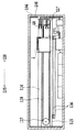
図1および図2は、本発明の一実施例に係るインクジェットプリンタの概略構造を表す断面図であり、本実施例の画像形成装置は、液体吐出ヘッドが主走査方向に移動するシリアルスキャン方式としての適用例である。図1において、プリンタ本体は、プリント媒体Sを給送する媒体給送部101と、プリント動作をするプリント部102と、本発明による液体としてのインクを補給するインク補給部103などから構成されている。
【0016】
104はプリンタ本体の外側に具えられたカバー、105は複数のプリント媒体Sを積載する設置台である。プリント媒体Sは、カバー104に設けられた挿入口104aに挿入され、排出口104bから排出される。カバー104内に設けられた側板106の内側には、搭載台108,給送ローラ109およびガイド部材111が設けられている。搭載台108は、プリント媒体Sを搭載する手段を構成するものであり、ばね107によって上方の給送ローラ109方向に付勢されている。給送ローラ109は、媒体給送手段を構成するものであり、搭載台108上における複数のプリント媒体Sの最上位置にあるものに当接する。ガイド部材111は、分離手段110によって分離された一枚のプリント媒体Sをプリント部102に向けて誘導する。
【0017】
112はガイド部材111の下流側を通過するプリント媒体Sを検出するためのフォトセンサである。113は給送されたプリント媒体Sを一定速度で搬送する一対の搬送ローラであり、114は画像をプリントした後のプリント媒体Sを搬出する一対の搬出ローラである。119はキャリッジであり、ガイド部材115,116によって図2中の矢印128,135の主走査方向(プリント媒体Sの幅方向)に移動自在に案内されている。キャリッジ119は、一対のプーリ117の間に掛け渡されたベルト118を介し、不図示のキャリッジモータから伝達される駆動力によって、主走査方向に移動する。8はキャリッジ19に交換可能に搭載される貯溜インクタンク(以下「サブタンク」ともいう)である。8は記録ヘッドであり、サブタンク1から供給されるインクを画像情報に基づいて吐出する。
【0018】
本実施形態の場合、サブタンク1と記録ヘッド8とは、一体的に結合したヘッドカートリッジを構成している。これらサブタンク1と記録ヘッド8とを個別に構成し、相互に着脱可能に結合させるようにしてもよく、またキャリッジ19に対して個別に装着可能としてもよい。
【0019】
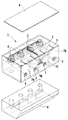
図3は本実施形態の記録ヘッド及びサブタンクの分解斜視図である。
【0020】
図4は、サブタンク及び記録ヘッドを示す斜視図である。
【0021】
インクを貯蔵するサブタンク1は内蔵するインク色ごとにインク室7が設けられており、ブラックインク室7B、シアンインク室7C、マゼンタインク室7M、イエローインク室7Yの順で並んでいる。そして、各インク室にはインク供給口が設けられており、サブタンク1の下方に接続される記録ヘッド8のインク路と連通するようになっている。記録ヘッド8はこのインク路を介して常に内部にインクが充填されている状態を保つようになっている。記録ヘッド8には複数のノズルが配列されており、この各ノズルよりインク滴を吐出して記録を行う。
【0022】
サブタンク1にはさらに、メインタンクからのインクを取り入れるインク取入口3がインク色ごとに設けられている。また、インク取り入れの際にインクの流れをよくするために吸引を行うので、その吸引のための総合吸引口2が設けられている。加えて、タンク内部を大気と同じ圧力に保つための大気連通口5が設けられている。これは各インクの混色を避けるため、インク色ごとに設けられている。また図から分かるように、本実施形態では大気連通口5を比較的小径にした。しかしながら本発明はこれに限らず、インクの付着によって空気の流れが悪くなるのを防ぐために大きくしてもよい。なお、メインタンクからのインク供給方法の詳細については後述する。
【0023】
サブタンク1はさらに、気液分離装置としての開口部6を有している。ここにはフッ素樹脂等からなる多孔質膜が貼りつけられている。この膜は發液性などの特性があるため、空気は通すがインクは通さない特徴がある。開口部6は総合吸引口2と繋がっているが、膜の特性から総合吸引口2から吸引が行われても、内部のインクは外に出ない仕組みとなっている。そして、この多孔質膜(開口部)6の上に適当な隙間を設けてカバー4が取りつけられている。なお、多孔質膜は四弗化エチレン樹脂、またはそれに類する樹脂多孔質材料によって形成された薄いシート状のものである。
【0024】
本実施形態では、非記録時にキャリッジがインクジェット記録装置本体のホームポジション側に移動すると、ホームポジションに設けられたメインタンクとキャリッジ上のサブタンクとが連通し、メインタンクからインクが供給される。
【0025】
図4に示すように、ホームポジション側に供給ジョイント9と吸引ジョイント10と密閉キャップ11とが設けられており、サブタンク1がホームポジションの所定位置に到達するとインク取入口3と供給ジョイント9とが接続するようになっている。そして供給ジョイント9はインク色ごとに不図示のチューブを介して不図示のメインタンクと接続されている。同様に総合吸引口2と吸引ジョイント10が接続し、大気連通口5と密閉キャップ11とが接続する。なお、供給ジョイント9、吸引ジョイント10、密閉キャップ11はそれぞれ先端がゴムなどの弾性部材で形成されており、サブタンク側の各開口部をしっかりと密閉するようになっている。
【0026】
これらホームポジションの所定位置に設けられた供給ジョイント9、吸引ジョイント10及び不図示のメインタンクなどを総称して供給部とする。
【0027】
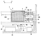
図5は、記録動作中の記録ヘッドと供給部を示す模式図である。
【0028】
サブタンク1と連結する記録ヘッド8は、ガイド軸12A及び12Bに沿って記録媒体上を矢印A1、A2に示す主走査方向に走査する。この走査の際、記録ヘッド8に配列された複数のノズル8Aよりインクを滴として記録媒体へ吐出して記録を行う。なお、記録動作は、まず記録媒体がプラテン22により記録開始位置までガイドされ、記録ヘッド8が記録媒体の一方端から他方端まで主走査方向に記録しながら移動する。そして記録媒体の端まで記録ヘッド8が移動すると、不図示の搬送手段によって主走査方向に対して垂直な方向に記録媒体が所定量だけ移動される。このように、記録ヘッドによる記録と記録媒体の搬送とを交互に繰り返すことにより、記録媒体全体に記録が施される。なお、サブタンク1と記録ヘッド8は不図示のキャリッジに搭載されているものとする。
【0029】
ノズルには電気熱変換体である発熱ヒータが設けられており、この発熱ヒータを発熱させることでインク中に瞬間的に気泡を発生させ、この気泡の生成圧力によって所定量のインクを吐出する。なお、本実施形態はバブルジェット方式を用いているが、本発明はこれに限らずピエゾ方式など他のインクジェット記録方法を用いてもよい。
【0030】
サブタンク1には、上述の通り、インク取入口3、総合吸引口2、大気連通口5、および記録ヘッド8との連通口(図示せず)が形成されている。さらに内部にはインクを吸収保持するためのインク吸収体13が収容されており、上面には、インクは通さずに、気体は透過させる多孔質膜6が取り付けられている。
【0031】
インクジェット記録装置本体側のホームポジションには、中空の突出部材14および15がガイド軸12に平行に設けられており、その外周部には、ばね16および17によって図中向かって左方に付勢される供給ジョイント9と吸引ジョイント10とがスライド可能にはめ合わされている。また、突出部材14および15には、供給ジョイント9および吸引ジョイント10によって開閉される貫通孔14Aおよび15Aが形成されている。さらに、突出部材14および15の先端は閉塞されており、その基端はそれぞれメインタンク(図示省略)および吸引ポンプ18に接続されている。
【0032】
19および20は、装置本体側に上下動可能に備えられた第1,第2のキャップ部材であり、記録ヘッド8を覆うものである。第2のキャップ部材20は、吸引ポンプ21を通して廃液タンク(図示省略)に接続されており、記録ヘッドの回復処理の際、記録ヘッドを覆い吸引してノズル内の増粘インクなどを取り除く。
【0033】
図6は記録ヘッド12がホームポジションに移動した状態を示す図である。
【0034】
キャリッジに搭載された記録ヘッド8及びサブタンク1がホームポジションへ移動すると、第1,第2のキャップ部材19、20が上昇し、第2のキャップ部材20は記録ヘッド8のノズル8Aをキャップする。また、このとき、サブタンク1が移動に伴い突出部材14,15に当接し、この当接によって供給ジョイント9が突出部材14の貫通孔14Aを閉じた状態でインク取入口3を密閉する。なお、供給ジョイント9は大気連通口5を閉じない位置にあるので、周囲温度の変化によってサブタンク1内部に圧力変動が生じた場合でも、この変動に応じて大気連通口5よりサブタンク内部と外部の間で空気を導入および排出することが可能である。
【0035】
一方、吸引ジョイント10は、突出部材15の貫通孔15Aを閉じたままサブタンク1側の総合吸引口2を閉じる。
【0036】
このような状態で、記録ヘッド8に対して回復処理が行われる。回復処理としては、吸引ポンプ21によって発生させた負圧を第2のキャップ部材20を介して記録ヘッド8に加え、ノズル8Aのインク吐出口からインクを強制的に吸引排出させる吸引処理や、ノズル8Aのインク吐出口から第2のキャップ部材20内にインクを吐出させる予備吐出処理などが挙げられる。このような回復処理を行うことにより、ノズルの状態を良好に保つことができる。また、非記録時や電源オフのときには、記録ヘッドをキャッピングしておくことで、インクの蒸発を防ぐことができる。
【0037】
次に図6に示すようにサブタンク側のインク取入口と供給ジョイントが接続した状態でのインク補給について説明する。
【0038】
図7はサブタンクにインクを補給している状態を示す図である。
【0039】
インクの補給動作時は、記録ヘッド8がホームポジションからさらに矢印A1方向のインク補給位置に移動する。記録ヘッド8がインク補給位置に移動したときは、第1のキャップ部材19によって記録ヘッド8のノズル8Aがキャッピングされる。このとき、供給ジョイント9はインク取入口3を閉じたまま、突出部材14との相対移動によって突出部材14の先端がサブタンク1内に入り込んだ状態にする。そしてこの状態で貫通孔14Aを開く。その貫通孔14Aは、サブタンク1内にて開口することによって、サブタンク1とメインタンクとの間のインク供給系を形成する。またこのとき密閉キャップ11は大気連通口5を閉じている。
【0040】
一方、吸引ジョイント10と突出部材15との相対移動によって突出部材15の先端がサブタンク内に入りこむ。この状態で貫通孔15Aを開く。総合吸引口2と多孔質膜6とは連通しているため、貫通孔15Aと多孔質膜6とは連通することとなる。
【0041】
このような状態でまず、吸引ポンプ18を作動させると、貫通孔15から多孔質膜6を通してサブタンク1の空気が吸引される。そしてその空気は廃液容器(図示省略)内に排出される。これによりサブタンク1内が負圧となり、その負圧によって、メインタンク内のインクがサブタンク1内に吸引される。サブタンク1内に流入したインクは、インク吸収体13に浸透し、その浸透が進むにつれてインクの液面が上昇する。インクの液面の上昇速度は,吸引ポンプ18の吸引力に依存するため、その作動量に応じて適正な速度に設定される。インクの液面が多孔質膜6に達したときは、その多孔質膜6がインク等の液体を通さないため、インクの補給は自動的に停止する。
【0042】
このようにしてインクのサブタンク側への補給動作が終了すると、キャリッジがホームポジションに戻る。さらに非記録時にはこの位置で停止し、記録時には所定の記録開始位置まで移動する。
【0043】
ところで、サブタンクに取りつけられている多孔質膜には、従来は、取りつけるときの熱によって表面の發液性が低下するという問題があった。本実施形態ではこのような問題を解決するために、次のような取りつけ方法で多孔質膜を取りつけている。
【0044】
図8はサブタンクに多孔質膜が取り付けられる時の分解斜視図である。
【0045】
24は多孔質膜6をサブタンクに固定する際に接合部を加熱する熱溶着ヘッドの先端部であり、不図示の保持手段で上下に可動する。25はサブタンクの上面板である。サブタンクの上面板25の所定位置には気液分離のための穴が開けられており、さらに多孔質膜6と溶着するために穴の外周に沿って凸部25Aがつけられている。この上面板25の裏側に図3に示すカバー部材4が一体成形されている。
【0046】
多孔質膜6はサブタンク1に取りつけられるときには、膜自体に發液処理が施されておらず、サブタンク1に熱溶着されてから發液処理が施される。
【0047】
図9(a)は多孔質膜が取り付けられた状態を示す斜視図で、図中上方向がサブタンクの内部になる。同図(b)は(a)のh―h断面図であり、多孔質膜を固定するときの熱溶着ヘッド24も示したものである。
【0048】
凸部25Aの上に多孔質膜6を不図示の位置決め手段で位置決めして載せた状態で同図(b)に示すように熱溶着ヘッド24が多孔質膜6に押しつけられ、熱溶着される。熱溶着ヘッド24は図の斜線部以外の中央部が空洞の円筒構造になっており、多孔質膜6を介して上面板25の凸部25A部分を加熱する。上面板25はノリルやポリプロピレンなどの樹脂成形部材で出来ており、熱溶着ヘッド24で180℃程度に加熱することにより溶融し多孔質膜6が接合される。
【0049】
このように多孔質膜をサブタンクに固定した状態で、インクに対する撥液性を向上させるために撥液処理剤を多孔質膜表面に処理する。
【0050】
多孔質膜の材質は、PTFE(ポリテトロフルオロエチレン)、ポリクロロトリフルオロエチレン、テトラフルオロエチレン−ヘキサフルオロプロピレン共重合体、テトラフルオロエチレン−パーフルオロアルキルビニルエーテル共重合体、テトラフルオロエチレン−エチレン共重合体などのフッ素樹脂が好ましい。これらフッ素樹脂は、通気性、耐薬品性に優れているために気液分離に有効である。本実施形態では多孔質膜として、PTFEからなるシートを一軸延伸法または二軸延伸法により多孔化した膜を用いており、本発明にはこの材料がもっとも適している。
【0051】
なお、PTFE多孔質膜をフィルタとして用いる場合には、強度を確保するために、通気性のある支持材と積層して用いてもよい。支持材としては、不織布、織布、ネットなどを用いることができる。
【0052】
撥液処理剤の種類および撥液処理方法に関しては特開平7―126428号公報、特開平9―103662号公報、特開2000―288367号公報に記載されているものを採用することができる。またこれらの方法に限らず、母材(ここではPTFE)よりも高い撥液性能を有する処理であれば良い。
【0053】
撥液処理剤としては、具体的には、各種の含フッ素ポリマーを用いることができる。含フッ素鎖を有する高分子は、繊維の表面に低表面自由エネルギーの皮膜を形成し、撥液効果を発揮する。含フッ素ポリマーとしては、パーフルオロアルキル基を有する高分子が好ましい。撥液処理方法は、撥液処理剤への含浸、同処理剤の塗布、スプレーなどにより行えばよい。撥液処理剤の塗布量は、充分な撥液性が得られ、かつフィルタの通気性が妨げられないように調整することが好ましい。
【0054】
また、一回で大量の撥液処理を行ないたいときは図9(a)の状態になったものを大量に保持できる治具に取り付け、まとめて処理すればよい。
【0055】
以上のように本実施形態では、多孔質膜を固定してから撥液処理を施すという工程なので撥液処理後には熱が加わることがなくなり、撥液性能を良好な状態で確保できる。
【0056】
(実施形態2)
実施形態1では、サブタンク本体に多孔質膜を熱溶着で固定したが、実公平6−47182号公報に記載されているようにサブタンク側の土台となる樹脂と多孔質膜を一体成形しても良い。一体成形後に上述した撥液処理を施せば良い。
【0063】
なお、実施形態1,2,3のいずれも多孔質膜をサブタンクに取り付ける構成になっているが、インクジェット記録装置本体側のサブタンクの総合吸引口と図5のインク補給状態において対向する位置に多孔質膜を備える構成であってもよい。なおこのときも実施形態1,2,3に示したように、多孔質膜を本体に取りつけた後に發液処理を施すものとする。
【0064】
この構成を図10〜14で説明する。
【0065】
図10において、901はインクを収容可能な貯留インクタンク、902は貯留インクタンク901内のインクをノズル部902Aから吐出可能な記録ヘッドであり、これらは、ガイド軸903A、903Bに沿って主走査方向(矢印A1,A2方向に)に移動される。貯留インクタンク901と記録ヘッド902は、ガイド軸903A、903Bにガイドされるキャリッジ(図示せず)に着脱自在に搭載することができる。貯留インクタンク901には、インク取入れ口901A、吸引口901B、大気連通口901C、および記録ヘッド902に連通されるインク供給口(図示せず)が形成されており、また貯留インクタンク901の内部にはインクを吸収保持するためのインク吸収体904が収容されている。
【0066】
本例の場合、貯留インクタンク901には、図11のように、シアン,マゼンタ,イエロー,ブラックのインクを収容するためのインク収容部901c、901m、901y、901bが形成されており、それぞれのインク収容部に、インク取入れ口901A、吸引口901B、大気連通口901C、およびインク供給口が形成されている。ブラックインクの使用頻度を考慮して、その収容部901Bは他の収容部よりも大きく形成されている。記録ヘッド902のノズル部902Aは、インク色毎に対応して設けられている。貯留インクタンク901と記録ヘッド902は、結合してインクジェットカートリッジを構成するものであってもよく、また貯留インクタンク901および記録ヘッド902は、各インク色毎に対応して分割された構造であってもよい。
【0067】
図10で921は、装置本体側に設けられた中空の突出部材であり、その外周部には、ばね922によって左方に付勢されるシール部材923がスライド可能にはめ合わされている。突出部材921には、シール部材923によって開閉される貴通孔921Aが形成されている。突出部材921の先端は閉塞されており、その基端は、図示しない補給インクタンクに接続されている。
【0068】
931はアーム部材であり、装置本体側の支持部材933に上下方向回動自在に軸支され、かつばね934によって下方に付勢されている。アーム部材931の先端側に取り付けられたシール部材932には、吸引口901Bに連通可能な開口932Aと、吸引口901Bおよび大気連通孔901Cを閉塞可能なシール部932Bが形成されている。開口932Aは、吸引管912を介して吸引ポンプ913に接続されている。本例の場合、インク収容部901c、901m、901y、901b毎の開口932Aは、図11のように吸引管912によって集合されてから、共通の吸引ポンプ913に接続されている。さらに、開口932Aには、インクは通さずに、気体は透過させる気体透過部材905が取り付けられている。この気体透過部材905は、上記実施例で説明した多孔質膜6と同じ材質で構成されており、表面にも同様な撥液処理がされている。一方、貯留インクタンク901側には、気体透過部材905を含めて、シール部材932の下面をワイビング可能なブレード936が備えられている。935は、アーム部材931の上動位置を規制するストッパー部材である。
【0069】
924,925は、装置本体側に上下動可能に備えられた第1,第2のキャップ部材であり、第2のキャップ部材925は、吸引ポンプ926を通して図示しない廃液タンクに接続されている。927は、記録ヘッド902による画像の記録位置に被記録媒体をガイドするためのプラテンである。被記録媒体は、図示しない搬送機構によって、主走査方向(矢印A1,A2方向)と交差する副走査方向に搬送される。インクを吐出しながらの記録ヘッド902の主走査と、被記録媒体の副走査方向の搬送動作とを繰り返すことによって、被記録媒体上に順次画像が形成される。
【0070】
記録動作時において、記録ヘッド902は、図12のホームポジションよりも左方の位置にて矢印A1,A2方向に移動しつつ、インクを吐出して画像を記録する。
【0071】
記録ヘッド902がホームポジションに移動したときは、図12のように、第1、第2のキャップ部材924、925が上昇し、第2のキャップ部材925によって記録ヘッド902のノズル部902Aがキャップされる。このとき、シール部材923は、突出部材913の貫通孔921Aを閉じたまま、インク取入れ口901Aを閉じ、またシール部材932は、吸引口901Bを閉じる。このように、取入れ口901A、吸引口901Bが閉じられることによって、貯留インクタンク901内のインクの増粘が防止される。気体透過部材905は、吸引口901から離れた図12中の右方に位置して、貯留インクタンク901内のインクとの接触が防止される。この結果、気体透過部材905とインクとの長期間の接触を避けることにより、気体透過部材905の性能劣化が防止される。ホームポジションにおける記録ヘッド902に対しては、画像の記録に寄与しないインクを排出させる回復処理によって、インクの吐出状態を良好に保つことができる。その回復処理としては、吸引ポンプ926によって発生させた負圧を第2のキャップ部材925内に導入して、ノズル部902Aのインク吐出口からインクを強制的に吸引排出させる処理、およびノズル部902Aのインク吐出口から第2のキャップ部材925内に向かってインクを吐出させる処理が含まれる。
【0072】
インクの補給動作時は、図13のように、記録ヘッド902がホームポジションからさらに矢印A1方向のインク補給位置に移動する。記録ヘッド902がインク補給位置に移動したときは、図13のように、第1、第2のキャップ部材924,925が上昇し、第1のキャップ部材924によって記録ヘッド902のノズル部902Aがキャップされる。そのキャップ部材924は、ノズル部902Aのインク吐出口を密閉する。このとき、シール部材923は、インク取入れ口901Aを閉じたまま、突出部材921との相対移動によって貫通孔921Aを開く。その貫通口921Aは、貯留インクタンク901内にて開口することによって、貯留インクタンク901と補給インクタンクとの間のインク供給系を形成する。また、シール部材932は、大気連通口901Cを閉じると共に、開口932Aを吸引口901Bに接続して、吸引口901Bと吸引ポンプ913との間の空気吸引系を形成する。気体透過部材905は、その吸引系中に介在する。
【0073】
インクの補給に際しては、吸引ポンプ913によって、貯留インクタンク901内の空気を気体透過部材905を通して吸引し、その空気を図示しない廃液容器内に排出する。これにより貯留インクタンク901内が負圧となり、その負圧によって、補給インクタンク内のインクが貯留インクタンク901内に吸引される。貯留インクタンク901内に流入したインクは、インク吸収体904に浸透し、その浸透が進むにつれてインクの液面が上昇する。インクの液面の上昇速度は,吸引ポンプ913の吸引力に依存するため、その作動量に応じて適正な速度に設定される。インクの液面が気体透過部材905に達したときは、その気体透過部材905がインク等の液体を通さないため、インクの補給は自動的に停止する。また、インク収容部901C、901M、901Y,901Bに対しては、同時にインクの補給が開始されて、先にインク充満状態となったものから順に、インクの補給が気体透過部材905によって自動的に止められることになる。
【0074】
このようなインクの補給動作の終了後は、記録ヘッド902をホームポジションまたは記録動作位置に移動させることによって、記録装置は図12または図10の状態に復帰する。
【0075】
なお、ブレード936は、貯留インクタンク901の移動に応じてシール部材932の下面に接することにより、図10中の2点鎖線のように、アーム部材931を上下に回動させつつ、気体透過部材905を含めてシール部材932の下面をワイピングする。このようなワイピングによって、気体透過部材905、開口932A、シール部932Bに付着した増粘インクなどの異物が除去されて、それらが良好な状態に保たれる。
【0076】
また、以上説明した実施例の構成に限られること無く、例えば記録ヘッドに対して供給されるインクを収容する容器本体と、該液体を取り出す開口と、前記容器本体を大気に対して連通する大気連通口とを具えたインクタンクであって、大気との連通がなされる個所に気液分離部材を本発明で開示される構成によって取り付ける構成としてもよい。
【0077】
貯留インクタンクと補給インクタンクをチューブで接続した方式について説明する。
【0078】
図14に示すように、キャリッジ1001に記録ヘッド1002および貯留インクタンク1010を配置し、補給インクタンク1003からチューブ1004を介して貯留インクタンク1010のインクを供給する方式がある。負圧を発生させる為に、記録ヘッド1002の重力高さ(水頭=ヘッドともいう)面よりも補給インクタンク1003を数センチ低い面−Hに配置することで達成している。1007は記録紙、1008は電源をオフにしたときや待機状態においてインクジェット記録ヘッド1002のノズルの乾燥を防ぐキャップである。
1009は補給インクタンクに固定された気体透過部材である。気体透過部材1009を介して補給インクタンク内のインクの減少にともない外部から空気を導入し、かつ外部へのインク漏れを防ぐ構成となっている。
【0079】
また補給インクタンクを持たずキャリッジ上の貯留インクタンクを交換する方式(オンキャリッジ方式)においても気体透過部材は採用可能である。貯留インクタンクの任意位置に気体透過部材を固定すればよい(図示省略)。
【0082】
また、以上説明したインクジェット装置の分野に限られること無く、水分の浸入を嫌う、例えば電気・電子機器などの内部と外部とを連通する連通部、例えばスイッチやボタンなどの内部への水分の侵入の可能性がある動作部分等といった気液分離部材を取り付けることが好ましいとされる個所に気液分離部材を取り付けるに際し本発明で開示した構成を適用することも可能であり、水分の浸入による故障などの恐れが抑止できる。
【0083】
なお、本発明は、液体の吐出を行わせるために利用されるエネルギーとして熱エネルギーを発生する手段(例えば電気熱変換体やレーザ光など)を具え、この熱エネルギーにより液体の状態変化を生起させるインクジェット方式の液体吐出ヘッドやヘッドカートリッジまたは画像形成装置において優れた効果をもたらすものである。かかる方式によれば、プリントの高密度化および高精細化が達成できるからである。
【0084】
その代表的な構成や原理については、例えば米国特許第4723129号明細書や、同第4740796号明細書に開示されている基本的な原理を用いて行うものが好ましい。この方式は、いわゆるオンデマンド型およびコンティニュアス型の何れにも適用可能であるが、特にオンデマンド型の場合には、液体が保持されているシートや流路に対応して配置される電気熱変換体に、プリント情報に対応した核沸騰を越える急速な温度上昇を与える少なくとも1つの駆動信号を印加することにより熱エネルギーを発生させ、液体吐出ヘッドの熱作用面に膜沸騰を生じさせ、結果的にこの駆動信号に一対一で対応した液体内の気泡を形成できるので有効である。この気泡の成長および収縮により、吐出口を介して液体を吐出させ、少なくとも1つの液滴を形成する。この駆動信号をパルス形状とすると、即時適切に気泡の成長収縮が行われるので、特に応答性に優れた液体の吐出が達成でき、より好ましい。このパルス形状の駆動信号としては、米国特許第4463359号明細書や、同第4345262号明細書に記載されているようなものが適している。
【0085】
なお、上記熱作用面の温度上昇率に関する発明の米国特許第4313124号明細書に記載されている条件を採用すると、さらに優れたプリントを行うことができる。
【0086】
液体吐出ヘッドの構成としては、上述の各明細書に開示されているような吐出口と液路と電気熱変換体との組合せ構成(電気熱変換体が液路に沿って配置された直線状液路または電気熱変換体が液路を挟んで吐出口と正対する直角液路)の他に、熱作用部が屈曲する領域に配置されている構成を開示する米国特許第4558333号明細書や、米国特許第4459600号明細書を用いた構成も本発明に含まれるものである。加えて、複数の電気熱変換体に対し、共通するスリットを電気熱変換体の吐出部とする構成を開示する特開昭59−123670号公報や、熱エネルギーの圧力波を吸収する開孔を吐出部に対応させる構成を開示した特開昭59−138461号公報に基いた構成としても、本発明の効果は有効である。すなわち、液体吐出ヘッドの形態がどのようなものであっても、本発明によればプリントを確実に効率良く行うことができるようになるからである。
【0087】
画像形成装置がプリントできるプリント媒体の最大幅に対応した長さを有するフルラインタイプの液体吐出ヘッドに対しても本発明は有効に適用できる。このような液体吐出ヘッドとしては、複数の液体吐出ヘッドの組合せによってその長さを満たす構成や、一体的に形成された1個の液体吐出ヘッドとしての構成の何れでもよい。
【0088】
上述した実施例の如きシリアルタイプのものでも、走査移動するキャリッジに対して一体的に固定された液体吐出ヘッドや、キャリッジに対して交換可能に装着されることでキャリッジとの電気的な接続や装置本体からの液体の供給が可能となる交換自在のチップインタイプのヘッドカートリッジ、あるいは液体吐出ヘッド自体に液体を貯溜したタンクが一体的または交換可能に設けられるヘッドカートリッジを用いた場合にも本発明は有効である。
【0089】
本発明の画像形成装置の構成として、液体吐出ヘッドからの液体の吐出状態を適正にするための回復手段や、予備的な補助手段などを付加することは本発明の効果を一層安定できるので、好ましいものである。これらを具体的に挙げれば、液体吐出ヘッドに対するキャッピング手段,クリーニング手段,加圧あるいは吸引手段,電気熱変換体やこれとは別の加熱素子あるいはこれらの組み合わせを用いて加熱を行う予備加熱手段,プリント作業とは別に吐出を行う予備吐出手段を挙げることができる。
【0090】
搭載される液体吐出ヘッドの種類や個数についても、例えば単色のインクに対応して1個のみが設けられたものの他、プリント色や濃度(明度)を異にする複数種のインクに対応して複数個設けられるものであってもよい。すなわち、例えば画像形成装置のプリントモードとしては黒色などの主流色のみのプリントモードだけではなく、液体吐出ヘッドを一体的に構成するか、複数個の組み合わせによるか何れでもよいが、異なる色の複色カラーまたは混色によるフルカラーの各プリントモードの少なくとも一つを備えた画像形成装置にも本発明は極めて有効である。この場合、プリント媒体の種類やプリントモードに応じてインクのプリント性を調整するための処理液(プリント性向上液)を専用あるいは共通の液体吐出ヘッドからプリント媒体に吐出することも有効である。
【0091】
【発明の効果】
以上のとおり、本発明を用いることにより、多孔質部材を多孔質部材保持部へ取りつけた後で多孔質部材に發液処理を施すため、發液処理後に熱が加わらない。したがって多孔質部材が変質することなく高い發液性を維持することができ、確実な気液分離処理を行うことができる。
【0092】
また、本発明の液体タンク製造方法で製造されたインクタンクは、常に高い發液性能を確保できるので、インク漏れを防ぐことができる。
【0093】
また、このようなインクタンクを用いたインクジェット記録装置は、この気液分離部を吸引することで、インクタンク内部を負圧にし、タンク内部に新しいインクを十分に供給することができる。さらに蓉液性能が十分に確保されているため、インクタンク内が一杯になった後に吸引を継続されてもあふれ出ることがない。
【0095】
また、多孔質部材をPTFEで作成することにより、より高い發液性能を発揮することができる。
【図面の簡単な説明】
【図1】 本実施形態のインクジェット記録装置を示す断面図である。
【図2】 図1のII−II線断面図である。
【図3】 サブタンク(インクタンク)及び記録ヘッドを示す分解斜視図である。
【図4】 サブタンク(インクタンク)及び記録ヘッドを示す斜視図である。
【図5】 記録動作中のインクジェット記録装置のインク供給部付近を示す部分模式図である。
【図6】 非記録時のインクジェット記録装置のインク供給部付近を示す部分模式図である。
【図7】 インク供給中のインクジェット記録装置のインク供給部付近を示す部分模式図である。
【図8】 サブタンクに多孔質膜が取りつけられるときの分解斜視図である。
【図9】 (a)は多孔質膜が取りつけられた状態を示す斜視図で、(b)は(a)のh−h断面図である。
【図10】 インクジェット記録装置本体側に気液分離部材を設けた場合のインクジェット記録装置の断面図である。
【図11】 図10の側面図である。
【図12】 電源オフ状態または待機状態を示すインクジェット記録装置の断面図である。
【図13】 インク補給中の状態を示すインクジェット記録装置の断面図である。
【図14】 本発明が適用されたインクジェットプリンタの概略図である。
【符号の説明】
1 サブタンク
2 総合吸引口
3 インク取入口
4 カバー部材
5 大気連通口
6 多孔質膜
7Y イエローインク室
7C シアンインク室
7B ブラックインク室
7M マゼンタインク室
8A ノズル
8 記録ヘッド
9 供給ジョイント
10 吸引ジョイント
11 密閉キャップ
12 ガイド軸
13 インク吸収体
14A 貫通孔
14 突出部材
15A 貫通孔
15 突出部材
16 ばね(供給ジョイント側)
17 ばね(吸引ジョイント側)
18 吸引ポンプ
19 キャップ部材
20 キャップ部材
21 吸引ポンプ
22 プラテン
25 上面板
25A 凸部
101 媒体給送部
102 プリント部
103 インク補給部
104 カバー
105 設置台
106 側板
107 ばね
108 搭載台
109 給送ローラ
110 分離手段
111 ガイド部材
112 フォトセンサ
113 搬送ローラ
114 搬出ローラ
115 ガイド部材
116 ガイド部材
117 プーリ
118 ベルト
119 キャリッジ
901 インクタンク
902 記録ヘッド
902A ノズル部
903 ガイド軸
904 インク吸収体
905 気体透過部材(気液分離部材、多孔質膜)
921 突出部材
922 ばね
923 シール部材
924 キャップ部材
925 キャップ部材
926 吸引ポンプ
927 プラテン
931 アーム部材
932 シール部材
933 指示部材
934 ばね
935 ストッパー部材
936 ブレード
1001 キャリッジ
1002 記録ヘッド
1003 補給インクタンク(メインタンク)
1007 記録紙(記録媒体)
1008 キャップ
1009 気体透過部材(気液分離部材、多孔質膜)
1010 貯留インクタンク(サブタンク)[0001]
BACKGROUND OF THE INVENTION
The present invention relates to a structure, a liquid tank, a method for manufacturing an ink jet recording apparatus, and an ink jet recording apparatus. More specifically, the structure, a liquid tank, and a method for manufacturing an ink jet recording apparatus in which a porous film is attached to a portion where gas-liquid separation is performed. And an ink jet recording apparatus.
[0002]
[Prior art]
In recent years, inkjet recording apparatuses have rapidly become widespread for reasons that color recording can be performed relatively easily and that the apparatus can be relatively small. In particular, serial type ink jet recording apparatuses are widely used for home use because the apparatus can be easily downsized. However, in the serial type, since the recording head is mounted on the carriage and the carriage is scanned to perform recording, there is a limit to the weight that can be mounted to operate the carriage normally. Accordingly, since the capacity of the ink tank integrated with the recording head (hereinafter referred to as “sub tank”) is limited, a large-capacity ink tank (hereinafter referred to as “main tank”) is provided separately from this ink tank. There is also a configuration in which ink is supplied from the main tank to the sub tank at any time during recording.
[0003]
As a method for supplying ink from the main tank to the sub tank, a pit-in method can be cited. In any position other than the carriage of the inkjet recording device A main tank is provided, and when the sub tank moves to a predetermined position, ink is supplied to the sub tank via a predetermined ink supply port. Many of the sub-tanks are provided with an air communication port opened to make the internal pressure atmospheric pressure, or on the contrary, a suction port for performing suction to make the internal pressure negative during supply. In order to prevent the ink inside the tank from leaking outside, a porous liquid film made of a fluororesin that allows only the gas to pass therethrough is used in these openings. For example, the invention described in Japanese Patent Application Laid-Open No. 5-201021 can be cited as an example in which a fluorine-containing porous porous membrane is used for the air communication port. In this invention, by applying a liquid processing agent to the porous liquid-liquid film in advance to improve the liquid-liquid property to the atmosphere communication port portion, by applying heat from the inside of the tank, the tank body and the porous film The molten film is thermally welded.
[0004]
[Problems to be solved by the invention]
However, when these porous soot films are thermally welded to the sub tank, the following problems may occur. That is, a temperature close to the melting point of polypropylene, which is the material of the sub tank, is applied to the part to be welded, but the heat applied at this time is applied not only to the part to be welded but also to other parts, and the heat As a result, the surface of the porous membrane changes. Due to this change, there is a problem in that the liquid permeability of the porous membrane deteriorates.
[0005]
SUMMARY OF THE INVENTION The present invention has been made in view of the above-described conventional problems, and an object thereof is to provide a structure, a liquid tank, a method for manufacturing an ink jet recording apparatus, and an ink jet recording apparatus that have an opening that maintains the liquid-liquid property of a porous film. .
[0006]
[Means for Solving the Problems]
The structure manufacturing method of the present invention is a structure having a communication portion that communicates the inside and the outside, and the structure is provided with a gas-liquid separation member that is arranged in the communication portion and allows only gas to pass therethrough. A method comprising: an attachment step of attaching the gas-liquid separation member to the communicating portion; and a liquid-liquid treatment step of subjecting the gas-liquid separation member to a liquid-liquid treatment with a liquid-treatment agent after the attachment step. It is characterized by.
[0007]
In addition, the liquid tank manufacturing method of the present invention includes a negative pressure introduction part for introducing a negative pressure inside, and a liquid intake part for taking in the liquid by a negative pressure introduced from the negative pressure introduction part. A method of manufacturing a liquid tank having a gas-liquid separation member that is provided in the negative pressure introduction portion and allows only gas to pass therethrough, the attachment step of attaching the gas-liquid separation member to the negative pressure introduction portion, and the attachment step After that, the gas-liquid separation member is provided with a soaking treatment process in which soaking treatment is performed with a soaking treatment agent.
[0008]
The method for manufacturing a liquid tank according to the present invention includes a container main body for storing a liquid, an opening for taking out the liquid, an air communication port for communicating the container main body with the atmosphere, and a gas disposed in the air communication port. A method of manufacturing a liquid tank comprising a gas-liquid separation member that allows only gas to pass through, an attachment step of attaching the gas-liquid separation member to the atmosphere communication port, and a liquid-liquid treating agent on the gas-liquid separation member after the attachment step And a soaking treatment process for conducting soaking treatment.
[0009]
In addition, a method for manufacturing an ink jet recording apparatus according to the present invention includes a negative pressure introducing portion for introducing a negative pressure therein, and a liquid intake portion for taking a liquid into the inside by the negative pressure introduced from the negative pressure introducing portion. And a negative pressure generating mechanism for introducing a liquid by applying a negative pressure to a liquid tank provided with only a gas disposed in the vicinity of a joint portion between the negative pressure introducing portion of the negative pressure generating mechanism. A method of manufacturing an ink jet recording apparatus comprising a gas-liquid separating member that passes through the gas-liquid separating member, Near the joint of the negative pressure generating mechanism It is characterized by comprising an attaching step and a soaking treatment step of subjecting the gas-liquid separating member to a soaking treatment with a soaking agent after the attaching step.
[0010]
In addition, the ink jet recording apparatus of the present invention includes a negative pressure generating mechanism for introducing a liquid by applying a negative pressure to the liquid tank manufactured by the above-described liquid tank manufacturing method. .
[0011]
According to the above configuration, since the liquid-liquid separation member is subjected to the liquid-liquid treatment after the gas-liquid separation member is attached to the communication portion, heat is not applied after the liquid-liquid treatment, so that the gas-liquid separation member does not change in quality. High lyophobicity can be maintained.
[0012]
In addition, since the liquid tank manufactured by the above-described liquid tank manufacturing method can always ensure high liquid-slipping performance, gas-liquid separation can be performed reliably.
[0013]
Therefore, in an ink jet recording apparatus incorporating such a liquid tank, ink can be supplied from the main tank to the liquid tank without ink leakage.
[0014]
DETAILED DESCRIPTION OF THE INVENTION
(Embodiment 1)
Embodiments of the present invention will be described below with reference to the drawings.
[0015]
1 and 2 are cross-sectional views illustrating a schematic structure of an ink jet printer according to an embodiment of the present invention. The image forming apparatus according to the present embodiment is a serial scan method in which a liquid discharge head moves in the main scanning direction. This is an application example. In FIG. 1, the printer main body includes a
[0016]
[0017]
[0018]
In the case of this embodiment, the
[0019]
FIG. 3 is an exploded perspective view of the recording head and the sub tank according to the present embodiment.
[0020]
FIG. 4 is a perspective view showing the sub tank and the recording head.
[0021]
The
[0022]
The
[0023]
The
[0024]
In this embodiment, when the carriage moves to the home position side of the ink jet recording apparatus main body during non-recording, the main tank provided at the home position communicates with the sub tank on the carriage, and ink is supplied from the main tank.
[0025]
As shown in FIG. 4, a
[0026]
The
[0027]
FIG. 5 is a schematic diagram illustrating a recording head and a supply unit during a recording operation.
[0028]
The
[0029]
The nozzle is provided with an exothermic heater that is an electrothermal converter. By generating heat from the exothermic heater, bubbles are instantaneously generated in the ink, and a predetermined amount of ink is ejected by the generated pressure of the bubbles. Although the present embodiment uses the bubble jet method, the present invention is not limited to this, and other ink jet recording methods such as a piezo method may be used.
[0030]
As described above, the
[0031]
At the home position on the main body side of the ink jet recording apparatus, hollow projecting
[0032]
[0033]
FIG. 6 is a diagram illustrating a state in which the
[0034]
When the
[0035]
On the other hand, the suction joint 10 closes the
[0036]
In such a state, the recovery process is performed on the
[0037]
Next, ink replenishment in a state where the ink intake on the sub tank side and the supply joint are connected as shown in FIG. 6 will be described.
[0038]
FIG. 7 is a diagram illustrating a state where ink is supplied to the sub tank.
[0039]
During the ink supply operation, the
[0040]
On the other hand, the tip of the protruding
[0041]
When the
[0042]
When the ink replenishment operation to the sub-tank side is thus completed, the carriage returns to the home position. Further, the recording medium stops at this position during non-recording, and moves to a predetermined recording start position during recording.
[0043]
By the way, the porous film attached to the sub-tank has conventionally had a problem that the liquid repellency of the surface is lowered by the heat at the time of attachment. In the present embodiment, in order to solve such a problem, the porous film is attached by the following attachment method.
[0044]
FIG. 8 is an exploded perspective view when the porous membrane is attached to the sub tank.
[0045]
[0046]
When the
[0047]
FIG. 9A is a perspective view showing a state in which the porous membrane is attached, and the upper direction in the drawing is the inside of the sub tank. FIG. 4B is a cross-sectional view taken along the line hh of FIG. 4A, and also shows a
[0048]
With the
[0049]
In this state, the surface of the porous film is treated with a liquid repellent agent in order to improve the liquid repellency with respect to the ink while the porous film is fixed to the sub tank.
[0050]
The material of the porous membrane is PTFE (polytetrafluoroethylene), polychlorotrifluoroethylene, tetrafluoroethylene-hexafluoropropylene copolymer, tetrafluoroethylene-perfluoroalkyl vinyl ether copolymer, tetrafluoroethylene-ethylene copolymer. A fluororesin such as a polymer is preferred. Since these fluororesins are excellent in air permeability and chemical resistance, they are effective for gas-liquid separation. In this embodiment, the porous membrane is a membrane made of a PTFE sheet made porous by a uniaxial stretching method or a biaxial stretching method, and this material is most suitable for the present invention.
[0051]
In addition, when using a PTFE porous membrane as a filter, in order to ensure intensity | strength, you may laminate | stack with a support material with air permeability. As the support material, a nonwoven fabric, a woven fabric, a net, or the like can be used.
[0052]
With respect to the type of liquid repellent treatment and the liquid repellent treatment method, those described in JP-A Nos. 7-126428, 9-103662, and 2000-288367 can be employed. Further, the present invention is not limited to these methods, and any treatment having higher liquid repellency than the base material (here, PTFE) may be used.
[0053]
As the liquid repellent treatment agent, specifically, various fluorine-containing polymers can be used. A polymer having a fluorine-containing chain forms a low surface free energy film on the surface of the fiber and exhibits a liquid repellent effect. As the fluorine-containing polymer, a polymer having a perfluoroalkyl group is preferable. The liquid repellent treatment method may be performed by impregnation of the liquid repellent treatment agent, application of the treatment agent, spraying, or the like. The coating amount of the liquid repellent treatment agent is preferably adjusted so that sufficient liquid repellency is obtained and the air permeability of the filter is not hindered.
[0054]
Further, when a large amount of liquid repellent treatment is to be performed at once, it is only necessary to attach the jig in a state shown in FIG.
[0055]
As described above, in the present embodiment, since the liquid repellent treatment is performed after fixing the porous film, heat is not applied after the liquid repellent treatment, and the liquid repellent performance can be ensured in a good state.
[0056]
(Embodiment 2)
In the first embodiment, the porous membrane is fixed to the sub-tank main body by heat welding. However, as described in Japanese Utility Model Publication No. 6-47182, the resin and the porous membrane serving as the base on the sub-tank side are integrally molded good. The liquid repellent treatment described above may be performed after the integral molding.
[0063]
In each of the first, second, and third embodiments, the porous film is attached to the sub tank. However, the porous film is provided at a position facing the general suction port of the sub tank on the ink jet recording apparatus main body side in the ink supply state of FIG. The structure provided with a membrane may be sufficient. At this time, as shown in the first, second, and third embodiments, it is assumed that after the porous film is attached to the main body, the slag treatment is performed.
[0064]
This configuration will be described with reference to FIGS.
[0065]
FIG. 901 is a stored ink tank capable of containing ink, 902 is a recording head capable of ejecting ink in the stored
[0066]
In this example, the stored
[0067]
In FIG.
[0068]
[0069]
[0070]
During the recording operation, the
[0071]
When the
[0072]
During ink supply operation, FIG. As described above, the
[0073]
When supplying ink, the
[0074]
After the ink replenishment operation is completed, the recording apparatus is moved by moving the
[0075]
The
[0076]
Further, without being limited to the configuration of the embodiment described above, for example, a container body that stores ink supplied to the recording head, an opening for taking out the liquid, and an atmosphere that communicates the container body with the atmosphere. The ink tank may include a communication port, and the gas-liquid separation member may be attached to a location where communication with the atmosphere is made by the configuration disclosed in the present invention.
[0077]
A system in which the storage ink tank and the replenishment ink tank are connected by a tube will be described.
[0078]
FIG. As shown in FIG. 4, there is a system in which the
[0079]
The gas permeable member can also be employed in a system (on-carriage system) in which the ink tank stored on the carriage is replaced without having a replenishment ink tank. A gas permeable member may be fixed at an arbitrary position of the stored ink tank (not shown).
[0082]
In addition, the present invention is not limited to the field of ink jet devices described above, and does not like the ingress of moisture. For example, moisture intrudes into the inside of a communication part that communicates the inside and outside of an electrical / electronic device, for example, a switch or a button. It is also possible to apply the configuration disclosed in the present invention when attaching the gas-liquid separation member to a place where it is preferable to attach the gas-liquid separation member, such as an operation part having a possibility of failure, and failure due to moisture intrusion. The fear such as can be suppressed.
[0083]
The present invention includes means (for example, an electrothermal converter or a laser beam) that generates thermal energy as energy used for discharging the liquid, and causes a change in the state of the liquid by the thermal energy. Ink jet type liquid discharge heads, head cartridges, or image forming apparatuses provide excellent effects. This is because according to such a method, high density and high definition of the print can be achieved.
[0084]
As for the typical configuration and principle, for example, those performed using the basic principle disclosed in US Pat. No. 4,723,129 and US Pat. No. 4,740,796 are preferable. This method can be applied to both a so-called on-demand type and a continuous type. In particular, in the case of the on-demand type, an electric circuit arranged corresponding to a sheet or a channel holding a liquid is used. Applying at least one drive signal that gives a rapid temperature rise exceeding the nucleate boiling corresponding to the print information to the thermal converter to generate thermal energy, causing film boiling on the heat acting surface of the liquid discharge head, As a result, it is effective because bubbles in the liquid corresponding to the drive signals on a one-to-one basis can be formed. Due to the growth and contraction of the bubbles, the liquid is discharged through the discharge port to form at least one droplet. It is more preferable that the drive signal has a pulse shape, since the bubble growth and contraction is performed immediately and appropriately, and thus it is possible to achieve liquid discharge with particularly excellent responsiveness. As this pulse-shaped drive signal, those described in US Pat. No. 4,463,359 and US Pat. No. 4,345,262 are suitable.
[0085]
If the conditions described in US Pat. No. 4,313,124 of the invention relating to the temperature rise rate of the heat acting surface are employed, further excellent printing can be performed.
[0086]
As a configuration of the liquid ejection head, a combination configuration of an ejection port, a liquid path, and an electrothermal transducer as disclosed in each of the above specifications (a linear shape in which the electrothermal transducer is disposed along the liquid path) US Pat. No. 4,558,333 which discloses a configuration in which a liquid passage or an electrothermal transducer is disposed in a region where the heat acting portion bends in addition to a liquid passage or a right-angle liquid passage facing the discharge port across the liquid passage) A configuration using US Pat. No. 4,459,600 is also included in the present invention. In addition, for a plurality of electrothermal transducers, Japanese Patent Application Laid-Open No. Sho 59-123670 that discloses a configuration in which a common slit is used as a discharge portion of the electrothermal transducer, or an aperture that absorbs pressure waves of thermal energy is provided. The effect of the present invention is effective even if the configuration is based on Japanese Patent Application Laid-Open No. 59-138461 which discloses a configuration corresponding to the discharge section. That is, whatever the form of the liquid ejection head is, according to the present invention, printing can be performed reliably and efficiently.
[0087]
The present invention can also be effectively applied to a full-line type liquid discharge head having a length corresponding to the maximum width of a print medium that can be printed by the image forming apparatus. As such a liquid discharge head, either a configuration satisfying the length by a combination of a plurality of liquid discharge heads or a configuration as a single liquid discharge head formed integrally may be used.
[0088]
Even in the serial type as in the above-described embodiments, the liquid discharge head fixed integrally with the carriage that is moved by scanning, or the electrical connection with the carriage by being exchangeably attached to the carriage. This is also possible when using a replaceable chip-in type head cartridge that can supply liquid from the main body of the apparatus, or a head cartridge in which a liquid storage head itself has a tank that stores liquid in an integrated or replaceable manner. The invention is effective.
[0089]
As the configuration of the image forming apparatus of the present invention, it is possible to further stabilize the effect of the present invention by adding a recovery means for making the liquid discharge state from the liquid discharge head appropriate, a preliminary auxiliary means, etc. It is preferable. Specifically, a capping unit, a cleaning unit, a pressurizing or sucking unit for the liquid discharge head, a preheating unit for heating using an electrothermal converter, a heating element different from this, or a combination thereof, A preliminary discharge unit that discharges separately from the printing operation can be given.
[0090]
As for the type and number of liquid discharge heads to be mounted, for example, only one corresponding to a single color ink is provided, and also corresponding to a plurality of types of inks having different print colors and densities (lightness). A plurality of them may be provided. That is, for example, the print mode of the image forming apparatus is not limited to a print mode of only a mainstream color such as black, but the liquid discharge head may be configured integrally or a plurality of combinations. The present invention is also very effective for an image forming apparatus having at least one of full-color print modes using color or mixed colors. In this case, it is also effective to discharge a processing liquid (printability improving liquid) for adjusting the printability of ink according to the type of print medium and the print mode from a dedicated or common liquid discharge head to the print medium.
[0091]
【The invention's effect】
As described above, by using the present invention, after the porous member is attached to the porous member holding portion, the porous member is subjected to the liquid-liquid treatment, so that no heat is applied after the liquid-liquid treatment. Therefore, high liquid permeability can be maintained without changing the porous member, and a reliable gas-liquid separation process can be performed.
[0092]
In addition, since the ink tank manufactured by the liquid tank manufacturing method of the present invention can always ensure high liquid spilling performance, ink leakage can be prevented.
[0093]
In addition, an ink jet recording apparatus using such an ink tank can suck the gas-liquid separation unit to make the inside of the ink tank have a negative pressure and sufficiently supply new ink to the inside of the tank. In addition, because the liquid performance is sufficiently secured, Even if suction is continued after the ink tank is full There is no overflow.
[0095]
Further, by creating the porous member with PTFE, it is possible to exhibit higher liquid-repellent performance.
[Brief description of the drawings]
FIG. 1 is a cross-sectional view illustrating an ink jet recording apparatus according to an embodiment.
FIG. 2 is a cross-sectional view taken along the line II-II in FIG.
FIG. 3 is an exploded perspective view showing a sub tank (ink tank) and a recording head.
FIG. 4 is a perspective view illustrating a sub tank (ink tank) and a recording head.
FIG. 5 is a partial schematic diagram illustrating the vicinity of an ink supply unit of an ink jet recording apparatus during a recording operation.
FIG. 6 is a partial schematic diagram illustrating the vicinity of an ink supply unit of an inkjet recording apparatus during non-recording.
FIG. 7 is a partial schematic diagram illustrating the vicinity of an ink supply unit of an ink jet recording apparatus during ink supply.
FIG. 8 is an exploded perspective view when a porous membrane is attached to a sub tank.
9A is a perspective view showing a state in which a porous film is attached, and FIG. 9B is a cross-sectional view taken along the line hh of FIG. 9A.
FIG. 10 is a cross-sectional view of an ink jet recording apparatus when a gas-liquid separating member is provided on the main body side of the ink jet recording apparatus.
11 is a side view of FIG.
FIG. 12 is a cross-sectional view of the ink jet recording apparatus showing a power-off state or a standby state.
FIG. 13 is a cross-sectional view of the ink jet recording apparatus showing a state during ink supply.
FIG. 14 is a schematic view of an ink jet printer to which the present invention is applied.
[Explanation of symbols]
1 Sub tank
2 General suction port
3 Ink intake
4 Cover members
5 Air communication port
6 Porous membrane
7Y Yellow ink chamber
7C cyan ink chamber
7B Black ink chamber
7M magenta ink chamber
8A nozzle
8 Recording head
9 Supply joint
10 Suction joint
11 Seal cap
12 Guide shaft
13 Ink absorber
14A Through hole
14 Protruding member
15A Through hole
15 Protruding member
16 Spring (supply joint side)
17 Spring (Suction joint side)
18 Suction pump
19 Cap member
20 Cap member
21 Suction pump
22 Platen
25 Top plate
25A Convex
101 Medium feeding part
102 Print section
103 Ink supply part
104 cover
105 Installation stand
106 Side plate
107 spring
108 mounting base
109 Feeding roller
110 Separation means
111 Guide member
112 Photosensor
113 Conveyor roller
114 Unloading roller
115 Guide member
116 Guide member
117 pulley
118 belt
119 Carriage
901 Ink tank
902 recording head
902A Nozzle part
903 Guide shaft
904 Ink absorber
905 Gas permeable member (gas-liquid separation member, porous membrane)
921 Protruding member
922 spring
923 Seal member
924 Cap member
925 cap member
926 Suction pump
927 platen
931 Arm member
932 Seal member
933 indicating member
934 spring
935 Stopper member
936 blade
1001 Carriage
1002 Recording head
1003 Replenishment ink tank (main tank)
1007 Recording paper (recording medium)
1008 cap
1009 Gas permeation member (gas-liquid separation member, porous membrane)
1010 Storage ink tank (sub tank)
Claims (12)
前記気液分離部材を前記連通部へ取りつける取りつけ工程と、
前記取りつけ工程の後に前記気液分離部材に發液処理剤で發液処理を施す發液処理工程と
を具えたことを特徴とする構造体の製造方法。A structure having a communication portion that communicates the inside and the outside, and a manufacturing method of a structure including a gas-liquid separation member that is disposed in the communication portion and allows only gas to pass through,
An attachment step of attaching the gas-liquid separation member to the communication portion;
A method for manufacturing a structure, comprising: a liquid-liquid treatment step of performing a liquid-liquid treatment with a liquid-liquid treatment agent on the gas-liquid separation member after the attachment step.
前記気液分離部材を前記負圧導入部へ取りつける取りつけ工程と、
前記取りつけ工程の後に前記気液分離部材に發液処理剤で發液処理を施す發液処理工程と
を具えたことを特徴とする液体タンクの製造方法。A negative pressure introduction part for introducing a negative pressure inside, a liquid intake part for taking in a liquid by a negative pressure introduced from the negative pressure introduction part, and a gas only provided in the negative pressure introduction part A method of manufacturing a liquid tank having a gas-liquid separation member that passes through the gas tank;
An attaching step of attaching the gas-liquid separating member to the negative pressure introducing portion;
A liquid tank manufacturing method, comprising: a liquid-liquid treatment process in which the gas-liquid separation member is subjected to a liquid-liquid treatment with a liquid-liquid treatment agent after the attachment process.
前記気液分離部材を前記大気連通口へ取りつける取りつけ工程と、
前記取りつけ工程の後に前記気液分離部材に發液処理剤で發液処理を施す發液処理工程と
を具えたことを特徴とする液体タンクの製造方法。A liquid tank comprising a container main body for storing liquid, an opening for taking out the liquid, an air communication port for communicating the container main body with the atmosphere, and a gas-liquid separation member that is disposed in the air communication port and allows only gas to pass therethrough. A manufacturing method of
An attaching step of attaching the gas-liquid separating member to the atmosphere communication port;
A liquid tank manufacturing method, comprising: a liquid-liquid treatment process in which the gas-liquid separation member is subjected to a liquid-liquid treatment with a liquid-liquid treatment agent after the attachment process.
前記気液分離部材を前記負圧発生機構の前記接合部近傍に取りつける取りつけ工程と、
前記取りつけ工程の後に前記気液分離部材に發液処理剤で發液処理を施す發液処理工程と
を具えたことを特徴とするインクジェット記録装置の製造方法。A negative pressure is introduced into the liquid tank having a negative pressure introduction part for introducing a negative pressure therein and a liquid intake part for taking in the liquid by the negative pressure introduced from the negative pressure introduction part. An ink jet recording apparatus comprising: a negative pressure generating mechanism for introducing liquid by acting; and a gas-liquid separation member that allows only gas disposed near a joint between the negative pressure introducing portion of the negative pressure generating mechanism A manufacturing method,
Mounting the gas-liquid separating member in the vicinity of the joint of the negative pressure generating mechanism ;
A method of manufacturing an ink jet recording apparatus, comprising: a liquid-liquid treatment step of performing a liquid-liquid treatment with a liquid-liquid treatment agent on the gas-liquid separation member after the mounting step.
Priority Applications (2)
| Application Number | Priority Date | Filing Date | Title |
|---|---|---|---|
| JP2001401669A JP3787522B2 (en) | 2001-12-28 | 2001-12-28 | Structure, liquid tank, ink jet recording apparatus manufacturing method, and ink jet recording apparatus |
| US10/303,834 US6799843B2 (en) | 2001-12-28 | 2002-11-26 | Method of manufacturing structural body, liquid tank and ink jet printing apparatus, and an ink jet printing apparatus |
Applications Claiming Priority (1)
| Application Number | Priority Date | Filing Date | Title |
|---|---|---|---|
| JP2001401669A JP3787522B2 (en) | 2001-12-28 | 2001-12-28 | Structure, liquid tank, ink jet recording apparatus manufacturing method, and ink jet recording apparatus |
Publications (3)
| Publication Number | Publication Date |
|---|---|
| JP2003200586A JP2003200586A (en) | 2003-07-15 |
| JP2003200586A5 JP2003200586A5 (en) | 2004-11-04 |
| JP3787522B2 true JP3787522B2 (en) | 2006-06-21 |
Family
ID=19189803
Family Applications (1)
| Application Number | Title | Priority Date | Filing Date |
|---|---|---|---|
| JP2001401669A Expired - Fee Related JP3787522B2 (en) | 2001-12-28 | 2001-12-28 | Structure, liquid tank, ink jet recording apparatus manufacturing method, and ink jet recording apparatus |
Country Status (2)
| Country | Link |
|---|---|
| US (1) | US6799843B2 (en) |
| JP (1) | JP3787522B2 (en) |
Families Citing this family (13)
| Publication number | Priority date | Publication date | Assignee | Title |
|---|---|---|---|---|
| JP2005306030A (en) * | 2004-03-24 | 2005-11-04 | Seiko Epson Corp | Attachment, attachment system, and liquid supplying device |
| US20050219281A1 (en) | 2004-03-24 | 2005-10-06 | Takeo Seino | Attachment and liquid supplying |
| US7399069B2 (en) * | 2004-10-13 | 2008-07-15 | Hewlett-Packard Development Company, L.P. | Fluid-ejection device connector |
| US7494215B2 (en) * | 2004-10-29 | 2009-02-24 | Hewlett-Packard Development Company, L.P. | Multiple chamber ink cartridge |
| JP4522245B2 (en) * | 2004-12-09 | 2010-08-11 | キヤノン株式会社 | Liquid container and inkjet recording apparatus |
| US7316471B2 (en) * | 2005-09-29 | 2008-01-08 | Brother Kogyo Kabushiki Kaishi | Ink cartridges |
| US7618135B2 (en) * | 2006-03-22 | 2009-11-17 | Hewlett-Packard Development Company, L.P. | Inkjet printing system with push priming |
| US7556365B2 (en) * | 2006-03-22 | 2009-07-07 | Hewlett-Packard Development Company, L.P. | Inkjet printing system with compliant printhead assembly |
| US7892330B2 (en) * | 2006-04-12 | 2011-02-22 | Fujifilm Corporation | Image forming apparatus |
| JP4933201B2 (en) * | 2006-09-04 | 2012-05-16 | 富士フイルム株式会社 | Liquid supply method |
| US8272690B2 (en) * | 2009-01-15 | 2012-09-25 | Cosco Management, Inc. | Juvenile vehicle seat with headrest-height controller |
| JP6977378B2 (en) * | 2017-07-31 | 2021-12-08 | ブラザー工業株式会社 | Liquid consuming device |
| JP7136310B2 (en) * | 2017-07-31 | 2022-09-13 | ブラザー工業株式会社 | liquid consumption device |
Family Cites Families (23)
| Publication number | Priority date | Publication date | Assignee | Title |
|---|---|---|---|---|
| SE371901B (en) * | 1973-12-28 | 1974-12-02 | Facit Ab | |
| CA1127227A (en) * | 1977-10-03 | 1982-07-06 | Ichiro Endo | Liquid jet recording process and apparatus therefor |
| JPS5936879B2 (en) | 1977-10-14 | 1984-09-06 | キヤノン株式会社 | Thermal transfer recording medium |
| US4330787A (en) * | 1978-10-31 | 1982-05-18 | Canon Kabushiki Kaisha | Liquid jet recording device |
| US4345262A (en) * | 1979-02-19 | 1982-08-17 | Canon Kabushiki Kaisha | Ink jet recording method |
| US4463359A (en) * | 1979-04-02 | 1984-07-31 | Canon Kabushiki Kaisha | Droplet generating method and apparatus thereof |
| US4313124A (en) * | 1979-05-18 | 1982-01-26 | Canon Kabushiki Kaisha | Liquid jet recording process and liquid jet recording head |
| US4558333A (en) * | 1981-07-09 | 1985-12-10 | Canon Kabushiki Kaisha | Liquid jet recording head |
| JPS59123670A (en) | 1982-12-28 | 1984-07-17 | Canon Inc | Ink jet head |
| JPS59138461A (en) | 1983-01-28 | 1984-08-08 | Canon Inc | Liquid jet recording apparatus |
| JPS6071260A (en) | 1983-09-28 | 1985-04-23 | Erumu:Kk | Recorder |
| JP3021204B2 (en) | 1991-08-30 | 2000-03-15 | キヤノン株式会社 | Liquid storage container, recording head unit using the same, and recording apparatus mounting the same |
| US5430471A (en) * | 1991-08-30 | 1995-07-04 | Canon Kabushiki Kaisha | Liquid container, recording head using same and recording apparatus using same |
| JP2854223B2 (en) | 1993-09-08 | 1999-02-03 | ジャパンゴアテックス株式会社 | Oil repellent waterproof ventilation filter |
| JPH09103662A (en) | 1995-10-10 | 1997-04-22 | Sumitomo Electric Ind Ltd | Oil-repelling and water-repelling filter |
| JP2000288367A (en) | 1999-04-05 | 2000-10-17 | Nok Corp | Manufacture of hydrophobic porous membrane |
| CA2310181C (en) * | 1999-05-31 | 2004-06-22 | Canon Kabushiki Kaisha | Ink tank, ink-jet cartridge, ink-supplying apparatus, ink-jet printing apparatus and method for supplying ink |
| JP2000334976A (en) * | 1999-05-31 | 2000-12-05 | Canon Inc | Ink jet recorder, ink supplying device and method for supplying ink |
| JP2001347686A (en) * | 2000-04-05 | 2001-12-18 | Nitto Denko Corp | Air filter for ink vessel and ink vessel using the same |
| US6629758B2 (en) * | 2000-04-19 | 2003-10-07 | Canon Kabushiki Kaisha | Joint device, ink jet recording apparatus having the same, and ink supplying device and method |
| JP2001301192A (en) * | 2000-04-24 | 2001-10-30 | Canon Inc | Ink jet recorder |
| JP3416614B2 (en) * | 2000-04-26 | 2003-06-16 | キヤノン株式会社 | Ink jet recording device |
| JP3787520B2 (en) | 2000-12-28 | 2006-06-21 | キヤノン株式会社 | Structure manufacturing method and manufacturing apparatus therefor |
-
2001
- 2001-12-28 JP JP2001401669A patent/JP3787522B2/en not_active Expired - Fee Related
-
2002
- 2002-11-26 US US10/303,834 patent/US6799843B2/en not_active Expired - Lifetime
Also Published As
| Publication number | Publication date |
|---|---|
| US6799843B2 (en) | 2004-10-05 |
| JP2003200586A (en) | 2003-07-15 |
| US20030122906A1 (en) | 2003-07-03 |
Similar Documents
| Publication | Publication Date | Title |
|---|---|---|
| JP4018513B2 (en) | Liquid storage device | |
| JP3787522B2 (en) | Structure, liquid tank, ink jet recording apparatus manufacturing method, and ink jet recording apparatus | |
| JP2001301192A (en) | Ink jet recorder | |
| JPH07195712A (en) | Ink jet device | |
| US10105953B2 (en) | Cleaning device of liquid ejection head and liquid ejection device | |
| US20090278900A1 (en) | Ink jet printing apparatus and ink tank for the same | |
| JP2001191557A (en) | Ink-jet type recording apparatus | |
| US6830321B2 (en) | Liquid tank and manufacture method therefor, ink jet apparatus and manufacture method therefor, and head cartridge and image forming apparatus | |
| JP2003200586A5 (en) | ||
| JP2002200774A (en) | Liquid tank, apparatus for replenishing liquid in relation to the same, its method, head cartrdige, and imaging apparatus | |
| JP2000301732A (en) | Ink jet recording apparatus | |
| WO1999021721A1 (en) | Ink jet printer with pressure fluctuation damping device | |
| JP2002192743A (en) | Ink jet recorder | |
| JP2003001858A (en) | Ink jet recorder and recovery system unit thereof | |
| JP3017155B2 (en) | Ink jet recording apparatus and cap member used in the apparatus | |
| JP2001301194A (en) | Ink tank, ink jet cartridge, ink supply unit, ink jet recorder, and method for supplying ink | |
| JP2003053995A (en) | Ink jet printer and ink tank | |
| JP3199466B2 (en) | Ink jet recording device | |
| JP4018521B2 (en) | Ink tank | |
| JP2831829B2 (en) | Ink jet recording device | |
| JP3347690B2 (en) | Ink jet recording device, ink supply device, and ink supply method | |
| JP3461282B2 (en) | Liquid ejection recording apparatus and liquid supply method thereof | |
| JP2004202934A (en) | Liquid tank and its manufacturing method and heat bonded head, head cartridge, image forming device, structure and inkjetting device | |
| US10618304B2 (en) | Liquid discharge device and liquid discharge apparatus | |
| JP2018083342A (en) | Inkjet printer |
Legal Events
| Date | Code | Title | Description |
|---|---|---|---|
| A977 | Report on retrieval |
Free format text: JAPANESE INTERMEDIATE CODE: A971007 Effective date: 20050623 |
|
| A131 | Notification of reasons for refusal |
Free format text: JAPANESE INTERMEDIATE CODE: A131 Effective date: 20050712 |
|
| A521 | Written amendment |
Free format text: JAPANESE INTERMEDIATE CODE: A523 Effective date: 20050912 |
|
| TRDD | Decision of grant or rejection written | ||
| A01 | Written decision to grant a patent or to grant a registration (utility model) |
Free format text: JAPANESE INTERMEDIATE CODE: A01 Effective date: 20060317 |
|
| A61 | First payment of annual fees (during grant procedure) |
Free format text: JAPANESE INTERMEDIATE CODE: A61 Effective date: 20060327 |
|
| R150 | Certificate of patent or registration of utility model |
Free format text: JAPANESE INTERMEDIATE CODE: R150 |
|
| FPAY | Renewal fee payment (event date is renewal date of database) |
Free format text: PAYMENT UNTIL: 20100331 Year of fee payment: 4 |
|
| FPAY | Renewal fee payment (event date is renewal date of database) |
Free format text: PAYMENT UNTIL: 20100331 Year of fee payment: 4 |
|
| FPAY | Renewal fee payment (event date is renewal date of database) |
Free format text: PAYMENT UNTIL: 20110331 Year of fee payment: 5 |
|
| FPAY | Renewal fee payment (event date is renewal date of database) |
Free format text: PAYMENT UNTIL: 20120331 Year of fee payment: 6 |
|
| FPAY | Renewal fee payment (event date is renewal date of database) |
Free format text: PAYMENT UNTIL: 20130331 Year of fee payment: 7 |
|
| FPAY | Renewal fee payment (event date is renewal date of database) |
Free format text: PAYMENT UNTIL: 20130331 Year of fee payment: 7 |
|
| FPAY | Renewal fee payment (event date is renewal date of database) |
Free format text: PAYMENT UNTIL: 20140331 Year of fee payment: 8 |
|
| LAPS | Cancellation because of no payment of annual fees |