JP3779115B2 - Automatic warehouse - Google Patents
Automatic warehouse Download PDFInfo
- Publication number
- JP3779115B2 JP3779115B2 JP37732799A JP37732799A JP3779115B2 JP 3779115 B2 JP3779115 B2 JP 3779115B2 JP 37732799 A JP37732799 A JP 37732799A JP 37732799 A JP37732799 A JP 37732799A JP 3779115 B2 JP3779115 B2 JP 3779115B2
- Authority
- JP
- Japan
- Prior art keywords
- track
- automatic guided
- load
- region
- automatic
- Prior art date
- Legal status (The legal status is an assumption and is not a legal conclusion. Google has not performed a legal analysis and makes no representation as to the accuracy of the status listed.)
- Expired - Lifetime
Links
Images


Landscapes
- Warehouses Or Storage Devices (AREA)
Description
【0001】
【発明の属する技術分野】
本発明は、荷の貯蔵・管理を行う自動倉庫に関し、特に、所定の軌道上を走行する無人搬送車を有する自動倉庫に関する。
【0002】
【従来の技術】
荷の貯蔵・管理を行う自動倉庫において、所定の軌道上を走行する無人搬送車に荷を搭載し、所定の箇所から他の箇所に荷を搬送するものがある。こうした自動倉庫では、1台の無人搬送車に搭載できる荷の数量が予め定められているため、所定の時間内に多くの荷を搬送しようすると、複数の無人搬送車を前述した軌道上に同時に走行させる必要がある。従来、こうした自動倉庫では、例えば荷の最大搬送量に応じて無人搬送車の台数が定められ、複数の台数の無人搬送車が前述した軌道上を同時に走行するように構成されている。
【0003】
【発明が解決しようとする課題】
ところが、従来の自動倉庫では、荷の搬送量が少なくなると、荷を搭載しない無人搬送車が生じ、この無人搬送車が軌道上を走行することで、バッテリや駆動部など、エネルギーや設備に無駄な消耗が生じるという問題がある。また、荷を搭載している無人搬送車と搭載していないものとの両者が同じ軌道上を走行するようになるため、荷を搭載している無人搬送車が少ないにも関わらず、荷を搭載していない無人搬送車が邪魔になって、荷を搭載している無人搬送車を効率よく運行させるのが難しい。従来、例えば、その日に予定される荷の搬送量など、荷の搬送予定に応じて自動倉庫の稼動前に軌道上から不要な無人搬送車を作業者が予め外しておくといったことは行われているものの、作業が煩雑で多大な労力を要したり、荷の搬送量が短時間で変化すると対応が難しいといった問題がある。
【0004】
本発明は、上述する事情に鑑みてなされたものであり、無人搬送車のバッテリや駆動部の消耗を抑制することができるとともに、効率的な無人搬送車の運行を実現することができる自動倉庫を提供することを目的とする。
【0005】
【課題を解決するための手段】
上記課題を解決するため、請求項1に係る発明は、第1領域の軌道上を走行する複数の無人搬送車に荷を搭載し、所定の箇所から他の箇所にこの荷を搬送する自動倉庫であって、第1領域とは異なる領域で無人搬送車を収容可能な第2領域と、第1領域から第2領域に無人搬送車を導くために第1領域の軌道から分岐して設けられる退避軌道と、第1領域の軌道上を走行する無人搬送車の台数を制御する制御部とを備える技術が採用される。
また、請求項2に係る発明は、請求項1に係る自動倉庫において、制御部が、荷の時間あたりの搬送量に応じて第1領域の軌道上を走行する無人搬送車の台数を定める手段を有する技術が採用される。
また、請求項3に係る発明は、請求項1または2に係る自動倉庫において、第2領域が、倉庫内のすべての無人搬送車を収容可能に設けられる技術が採用される。
本発明は、このような技術を採用することにより、上述した課題を解決することができる。
【0006】
【発明の実施の形態】
以下、本発明に係る自動倉庫の一実施形態について図面を参照して説明する。
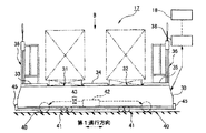
図2には、本実施形態の自動倉庫の構成が示されている。この自動倉庫Sは、パレットに搭載された荷を一時保管するための複数の収納棚10、11、12と、この収納棚10、11、12に対して荷の受け渡しを行うクレーン13、14と、このクレーン13、14に荷を供給するために所定のルートで荷を搬送するコンベア部15と、積荷作業が行われる作業台16と、この作業台16の側を所定の軌道に沿って走行する無人搬送車17と、倉庫内を統括して制御する主制御部18とを備えている。
【0007】
収納棚10、11、12は、互いに間隔を空けて平行に並べて配設されており、この収納棚10、11、12の間隔位置に敷設されたレール上を前述した各クレーン13、14が走行するようになっている。また、収納棚10、11、12は、左右および上下方向に配列された複数の収納部20を有しており、例えばコンベア部15から供給される荷がクレーン13、14によって収納部20ごとに種類を分けて収納されるようになっている。
【0008】
また、クレーン13、14は、図3に示されるように、収納棚10、11、12の荷Pを取り出してその荷Pを作業台16上の所定位置(荷受位置PK)に置き、空になったパレットを荷受位置PKから回収してコンベア部15(図2参照)に受け渡すようになっている。荷受位置PKは、クレーン13、14の走行方向に複数設けられていて、各荷受位置PKごとにそこに置かれる荷の種類が予め定められている。また、クレーン13、14は、空のパレットを荷受位置PKから回収すると、その荷受位置PKに対応する種類の荷を収納棚10、11、12から取り出してその荷受位置PKに荷を補充するようになっている。
【0009】
作業台16は、前述した荷受位置PKの荷を無人搬送車17に積み込むためのものであり、上面が床面から所定の高さに形成されている。作業台16には、積荷作業を行うための位置(積荷作業箇所PG)が予め定められており、この積荷作業箇所PGは、荷受位置PKと同様、クレーン13、14の走行方向に複数設けられている。また、作業台16の側面には、積荷作業箇所PGの位置を示すための図示しないマークが設けられており、このマークは、後述するように、無人搬送車17の停止位置を位置決めするために用いられるものである。
【0010】
無人搬送車17は、図4に示されるように、所定の軌道上を走行する台車部30、荷を搭載するための2つの搭載部(第1搭載部31、第2搭載部32)、積荷作業時の作業員の足場となる足場部33,34,35、台車部30の上部に立設されるフェンス部36、前述した主制御部18との間で情報の送受信を行うための通信部38を含んで構成されている。
【0011】
台車部30は、軌道上を転動する駆動輪40および従動輪41、駆動輪40を駆動するモータなどの駆動手段42、所定のマークを検出するための停止用検出手段43、走行方向の障害物を検出するための図示しない障害物検出手段、他の物体との接触時の衝撃を緩和するためのダンパ45等を備えている。なお、台車部30の移動方向のうち、図4の紙面内左右方向を第1進行方向、台車部30が移動する面内で第1進行方向と直交する方向を第2進行方向と呼ぶことにする。
【0012】
また、台車部30は、主制御部18から指示を受けると、駆動手段42を介して駆動輪40を駆動し、例えば磁気誘導されることにより、前述した軌道に沿って走行するようになっている。さらに、台車部30は、走行中において主制御部18から所定の位置に停止するように指示を受けると、停止用検出手段43を介して、例えば前述した作業台16の側面に設けられた所定のマークを検出し、指示された位置で駆動輪40を停止させるようになっている。また、障害物検出手段は、例えば光を利用した反射型のセンサであって、障害物が所定の距離よりも近くに存在すると信号を出力するものであり、台車部30は、この信号によって駆動輪40を停止させるようになっている。
【0013】
第1および第2搭載部31、32は、集荷用のパレットが搭載できるように上述した台車部30の上面側で第1進行方向に間隔を空けて配され、図5に示されるように、周面でパレットの底部を支持する略円筒状の支持部材46が水平に並べて配設されている。
【0014】
図6には、上述した自動倉庫S内に敷設された無人搬送車17用の軌道の様子が示されている。
本実施形態の自動倉庫Sは、無人搬送車17用の軌道として、前述した収納棚10、11、12および作業台16の周囲を囲んで敷設される巡回軌道50と、この巡回軌道50の周囲に敷設される周回軌道51と、巡回軌道50と周回軌道51とを連絡する連絡軌道52と、周回軌道51から分岐して敷設される退避軌道53とを有している。
【0015】
巡回軌道50は、無人搬送車17に荷を搭載するための軌道であって、収納棚10、11、12を挟んだ片方の作業台16からもう一方の作業台16まで、すべての積荷作業箇所PG(図2参照)の側を無人搬送車17が通過できるように配されている。周回軌道51は、収納棚10、11、12の周囲を無人搬送車17が周回できるように配されている。さらに、周回軌道51は、無人搬送車17とコンベア部15との間で荷の受渡しができるように、前述したコンベア部15を通過するように配されている。連絡軌道52は、巡回軌道50上の各積荷作業箇所PG(図2参照)から周回軌道51に無人搬送車17が迂回できるように、巡回軌道50および周回軌道51にほぼ垂直に交差するように設けられている。なおここで、こうした荷の搬送を行うための軌道、すなわち巡回軌道50、周回軌道51、連絡軌道52が敷設された領域を搬送領域HRとする。
【0016】
退避軌道53は、上述した搬送領域HRとは異なる領域で無人搬送車17を収容可能に設けられる退避領域TRに無人搬送車17を導くための軌道である。退避領域TRは、本実施形態では、少なくとも自動倉庫S内に装備される台数の無人搬送車17を個別に収容できるような大きさで、周回軌道51の外側に複数設けられている。また、退避軌道53は、周回軌道51上の無人搬送車17を空いている退避領域TRに退避させたり、任意の退避領域TRに収容されている無人搬送車17を他の無人搬送車17を動かすことなく周回軌道51に導いたりすることが可能となるように設けられている。
【0017】
また、主制御部18は、上述した各稼動部を統括して制御するものであり、本実施形態では、倉庫内の荷の時間あたりの搬送量に応じて搬送領域HR内の軌道上を走行する無人搬送車17の台数を定める回路(手段)を有している。
【0018】
次に、このように構成された自動倉庫Sにおいて、特に積荷作業に伴う自動倉庫Sの動作について図1を参照して説明する。前提として、自動倉庫Sの運転開始前には、図1(A)に示されるように、倉庫内のすべての無人搬送車17が退避領域TRに収容されているものとする。
【0019】
自動倉庫Sの運転が開始されると、主制御部18は、例えば予め入力されている所定の時間内における荷の搬送量に基づいて、係る時間内に必要な所定台数の無人搬送車17を退避領域TRから搬送領域HRの周回軌道51上に導く。
【0020】
周回軌道51に導かれた無人搬送車17は、図1(B)に示されるように、まず、周回軌道51に沿って走行してコンベア部15に移動し、そこで空のパレットを受け取る。なお、受け取ったパレットは第1および第2搭載部31、32(図5参照)に搭載される。
【0021】
続いて、無人搬送車17は、主制御部18から指示を受けることにより、周回軌道51から連絡軌道52を介して巡回軌道50に移動し、停止用検出手段43によって作業台16の所定のマークを検出して目的の積荷作業箇所PG(図2参照)の側に停止する。
【0022】
無人搬送車17が停止すると、その積荷作業箇所PGの作業者(図3参照)は、必要数量の荷を荷受位置PKから取り出し、無人搬送車17のパレット上に搭載する。そして、荷の積荷作業が終了すると、無人搬送車17は、主制御部18に指示された次の積荷作業箇所PGに移動する。
【0023】
次の積荷作業箇所PGに無人搬送車17が停止すると、上述したものと同様に、作業者は、必要数量の荷を荷受位置PKから取り出し、無人搬送車17のパレット上に搭載する。
【0024】
こうして、主制御部18に指定された積荷作業箇所PGを無人搬送車17が巡回することにより、各積荷作業箇所PGにおいて上述した一連の積荷作業が繰り返し行われ、異なる種類の荷が無人搬送車17のパレット上に積み付けられて、パレット上に出荷用の1ユニットとなる荷の集合体が形成される。そして、整った荷姿に完成された出荷ユニットは、無人搬送車17によってコンベア部15に搬送され、外部に搬出される。
【0025】
出荷ユニットの搬出を終えた無人搬送車17は、コンベア部15で新たな空のパレットを受け取ると、上述した一連の動作を繰り返し、搬送領域HRの軌道上を走行して積荷作業箇所PGを巡回する。また、主制御部18は、荷の時間あたりの搬送量に応じて搬送領域HRを走行する無人搬送車17の台数を定め、例えば時間あたりの荷の搬送量が少なくなると、図1(C)に示されるように、出荷ユニットの搬出を終えた無人搬送車17を退避領域TRに退避させる。逆に、時間あたりの荷の搬送量が多くなってくると、主制御部18は、退避領域TRの無人搬送車17を搬送領域HRに移動させて、搬送領域HR内の無人搬送車17の台数を増やす。このように、主制御部18は、無人搬送車17の台数を随時変更しながら、無人搬送車17による荷の搬送を実行させ、すべての荷の搬送作業が終了すると、退避領域TRにすべての無人搬送車を退避させ、荷の搬送作業を終了する。
【0026】
このように、本実施形態の自動倉庫によれば、搬送領域HRの無人搬送車17の台数が主制御部18で制御されるため、例えば荷の搬送量が少ない場合には、不要な無人搬送車17を退避領域TRに退避させることで、無人搬送車17のバッテリや駆動部の消耗を抑制することができる。しかも、荷の時間あたりの搬送量に応じて搬送領域HRの軌道上を走行する無人搬送車17の台数を主制御部18が定めるため、荷の搬送量が短時間で変化する場合にも対応して、無人搬送車17を適宜退避領域TRに退避させたり、搬送領域HR内の無人搬送車17を増やしたりすることができる。よって、搬送領域HR内を走行する無人搬送車17の台数が適切に制御されるため、実際の荷の搬送に不要な動作が少なくなり、効率的な無人搬送車17の運行を実現することができる。さらに、本実施形態の自動倉庫では、倉庫の稼動が終わると倉庫内のすべての無人搬送車17が退避領域TRに収容されるので、搬送領域HRの軌道の補修や点検・整備など、搬送領域HR内のメンテナンス作業時において無人搬送車17が邪魔になるといったことがなく、効率的に作業を行うことができる。
【0027】
なお、上述した実施形態において示した各構成部材の諸形状や組み合わせ等は一例であって、本発明の主旨から逸脱しない範囲において設計要求等に基づき種々変更可能である。上述した実施形態では、退避領域TRは、周回軌道51の外側、すなわち搬送領域HRの外側に設けられているが、これに限るものではなく、搬送領域HRの内側に設けたり、あるいは軌道を上下多層に立体的に構成して搬送領域HRと退避領域とを別々の階層に配設してもよい。
【0028】
【発明の効果】
以上説明したように、この発明によれば以下の効果を得ることができる。
請求項1に係る自動倉庫では、荷の搬送が行われる第1領域の無人搬送車の台数が制御部で制御されるため、例えば荷の搬送量が少ない場合には、不要な無人搬送車を第2領域に退避させることで、無人搬送車のバッテリや駆動部の消耗を抑制することができる。しかも、制御部で自動的に台数制御を行えるため、第1領域の無人搬送車の台数を柔軟に制御することができる。
【0029】
請求項2に係る自動倉庫では、荷の時間あたりの搬送量に応じて第1領域の軌道上を走行する無人搬送車の台数を制御部が定めるため、実際の荷の搬送に不要な動作が少なくなり、効率的な無人搬送車の運行を実現することができる。
【0030】
請求項3に係る自動倉庫では、倉庫内のすべての無人搬送車を第2領域に収容することが可能であるので、例えば第1領域の軌道の補修作業など、第1領域内のメンテナンス作業時に無人搬送車が邪魔になることがなく、作業効率を向上させることができる。
【図面の簡単な説明】
【図1】 本発明に係る自動倉庫の一実施形態における軌道上を走行する無人搬送車の様子を示す図である。
【図2】 図1の自動倉庫の概略構成を示す平面図である。
【図3】 図2に示すA矢視図である。
【図4】 図1の自動倉庫の無人搬送車を示す側面図である。
【図5】 図4に示すB矢視図である。
【図6】 図2の自動倉庫の軌道を示す平面図である。
【符号の説明】
S 自動倉庫
HR 搬送領域(第1領域)
TR 退避領域(第2領域)
17 無人搬送車
18 主制御部(制御部)
50 巡回軌道
51 周回軌道
52 連絡軌道
53 退避軌道[0001]
BACKGROUND OF THE INVENTION
The present invention relates to an automatic warehouse for storing and managing loads, and more particularly to an automatic warehouse having an automatic guided vehicle traveling on a predetermined track.
[0002]
[Prior art]
2. Description of the Related Art Some automated warehouses that store and manage loads include loading a load on an automated guided vehicle traveling on a predetermined track and transporting the load from a predetermined location to another location. In such an automatic warehouse, since the number of loads that can be mounted on one automatic guided vehicle is determined in advance, when a large number of loads are transported within a predetermined time, a plurality of automatic guided vehicles are simultaneously placed on the aforementioned track. Need to run. Conventionally, in such an automatic warehouse, the number of automatic guided vehicles is determined according to, for example, the maximum amount of load transported, and a plurality of automatic guided vehicles are configured to travel simultaneously on the aforementioned track.
[0003]
[Problems to be solved by the invention]
However, in a conventional automated warehouse, when the load transport amount decreases, an unmanned transport vehicle that does not load the load is generated, and this unmanned transport vehicle travels on the track, which is wasted on energy and equipment such as a battery and a drive unit. There is a problem that excessive wear occurs. In addition, both the automated guided vehicle loaded with the load and the unloaded loaded vehicle will run on the same track, so the load is loaded even though there are few automated guided vehicles loaded with the load. It is difficult to operate an automated guided vehicle equipped with a load efficiently because an unmanned automated guided vehicle is in the way. Conventionally, for example, an operator automatically removes an unnecessary automatic guided vehicle from the track before the operation of an automatic warehouse according to a scheduled load transportation such as a scheduled transportation amount of the day. However, there are problems that the work is complicated and requires a lot of labor, and that it is difficult to cope with the change in the transport amount of the load in a short time.
[0004]
The present invention has been made in view of the circumstances described above, and is an automatic warehouse that can suppress the consumption of the battery and the drive unit of the automatic guided vehicle and can realize efficient operation of the automatic guided vehicle. The purpose is to provide.
[0005]
[Means for Solving the Problems]
In order to solve the above-described problem, an invention according to claim 1 is directed to an automatic warehouse in which a load is mounted on a plurality of automatic guided vehicles traveling on a track in a first region, and the load is transported from a predetermined location to another location. In addition, a second region that can accommodate the automatic guided vehicle in a region different from the first region, and a branch from the track of the first region to guide the automatic guided vehicle from the first region to the second region are provided. A technique including a retreating track and a control unit that controls the number of automatic guided vehicles traveling on the track in the first region is employed.
The invention according to claim 2 is the automatic warehouse according to claim 1, wherein the control unit determines the number of automatic guided vehicles traveling on the track in the first region according to the transport amount per hour of the load. The technology which has is adopted.
The invention according to claim 3 employs a technique in which, in the automatic warehouse according to claim 1 or 2, the second region is provided so as to accommodate all automatic guided vehicles in the warehouse.
The present invention can solve the above-described problems by adopting such a technique.
[0006]
DETAILED DESCRIPTION OF THE INVENTION
Hereinafter, an embodiment of an automatic warehouse according to the present invention will be described with reference to the drawings.
FIG. 2 shows the configuration of the automatic warehouse of the present embodiment. The automatic warehouse S includes a plurality of
[0007]
The
[0008]
Further, as shown in FIG. 3, the
[0009]
The work table 16 is for loading the load at the above-described load receiving position PK onto the automatic guided
[0010]
As shown in FIG. 4, the automatic guided
[0011]
The
[0012]
Further, when receiving an instruction from the
[0013]
The first and second mounting
[0014]
FIG. 6 shows the state of the track for the automatic guided
The automatic warehouse S according to the present embodiment includes, as a track for the automatic guided
[0015]
The traveling
[0016]
The
[0017]
The
[0018]
Next, in the automatic warehouse S configured as described above, the operation of the automatic warehouse S particularly associated with the loading operation will be described with reference to FIG. As a premise, before the operation of the automatic warehouse S, as shown in FIG. 1A, all automatic guided
[0019]
When the operation of the automatic warehouse S is started, the
[0020]
As shown in FIG. 1B, the automatic guided
[0021]
Subsequently, upon receiving an instruction from the
[0022]
When the automatic guided
[0023]
When the automated guided
[0024]
In this way, when the automated guided
[0025]
When the
[0026]
As described above, according to the automatic warehouse of the present embodiment, the number of the automatic guided
[0027]
The various shapes and combinations of the constituent members shown in the above-described embodiments are merely examples, and various changes can be made based on design requirements and the like without departing from the gist of the present invention. In the above-described embodiment, the retreat area TR is provided outside the
[0028]
【The invention's effect】
As described above, according to the present invention, the following effects can be obtained.
In the automatic warehouse according to claim 1, since the number of the automatic guided vehicles in the first region where the load is transported is controlled by the control unit, for example, when the load transport amount is small, an unnecessary automatic guided vehicle is installed. By retracting to the second region, it is possible to suppress the consumption of the battery and the drive unit of the automatic guided vehicle. In addition, since the number of units can be automatically controlled by the control unit, the number of automatic guided vehicles in the first region can be flexibly controlled.
[0029]
In the automatic warehouse according to claim 2, since the control unit determines the number of automatic guided vehicles traveling on the track in the first region according to the transport amount per hour of the load, an operation unnecessary for actual load transport is performed. The number of vehicles can be reduced and efficient automated guided vehicle operation can be realized.
[0030]
In the automatic warehouse according to the third aspect, since all the automatic guided vehicles in the warehouse can be accommodated in the second area, for example, during maintenance work in the first area such as track repair work in the first area. The automatic guided vehicle does not get in the way and work efficiency can be improved.
[Brief description of the drawings]
FIG. 1 is a diagram showing a state of an automatic guided vehicle traveling on a track in an embodiment of an automatic warehouse according to the present invention.
2 is a plan view showing a schematic configuration of the automatic warehouse in FIG. 1. FIG.
FIG. 3 is a view taken in the direction of an arrow A shown in FIG.
4 is a side view showing an automatic guided vehicle of the automatic warehouse in FIG. 1. FIG.
FIG. 5 is a view taken in the direction of arrow B shown in FIG.
6 is a plan view showing a track of the automatic warehouse in FIG. 2. FIG.
[Explanation of symbols]
S Automatic warehouse HR Transport area (first area)
TR evacuation area (second area)
17 Automated guided
50
Claims (3)
前記第1領域の軌道は、前記無人搬送車に対して前記荷を搭載するための第1の軌道と、該第1の軌道に沿って敷設される第2の軌道と、前記第1の軌道と前記第2の軌道とを連絡する第3の軌道とを備え、
前記第1の軌道は前記無人搬送車に前記荷を搭載する箇所を囲んで敷設される巡回軌道であり、前記第2の軌道は前記巡回軌道の周囲に敷設される周回軌道である
ことを特徴とする自動倉庫。An automatic warehouse in which a load is loaded on a plurality of automatic guided vehicles traveling on a track in a first region and the load is transported from a predetermined location to another location, and the unmanned vehicle is in a region different from the first region. A second region that can accommodate a transport vehicle, a retreat track that is branched from the track of the first region to guide the automatic guided vehicle from the first region to the second region, and the first region A control unit for controlling the number of the automatic guided vehicles traveling on the track ,
The track of the first region includes a first track for mounting the load on the automatic guided vehicle, a second track laid along the first track, and the first track. And a third track that communicates with the second track,
The first track is a circular track laid around the place where the load is loaded on the automatic guided vehicle, and the second track is a circular track laid around the circular track. And automatic warehouse.
Priority Applications (1)
| Application Number | Priority Date | Filing Date | Title |
|---|---|---|---|
| JP37732799A JP3779115B2 (en) | 1999-12-28 | 1999-12-28 | Automatic warehouse |
Applications Claiming Priority (1)
| Application Number | Priority Date | Filing Date | Title |
|---|---|---|---|
| JP37732799A JP3779115B2 (en) | 1999-12-28 | 1999-12-28 | Automatic warehouse |
Publications (2)
| Publication Number | Publication Date |
|---|---|
| JP2001187604A JP2001187604A (en) | 2001-07-10 |
| JP3779115B2 true JP3779115B2 (en) | 2006-05-24 |
Family
ID=18508629
Family Applications (1)
| Application Number | Title | Priority Date | Filing Date |
|---|---|---|---|
| JP37732799A Expired - Lifetime JP3779115B2 (en) | 1999-12-28 | 1999-12-28 | Automatic warehouse |
Country Status (1)
| Country | Link |
|---|---|
| JP (1) | JP3779115B2 (en) |
Families Citing this family (2)
| Publication number | Priority date | Publication date | Assignee | Title |
|---|---|---|---|---|
| JP4462175B2 (en) * | 2005-11-24 | 2010-05-12 | パナソニック電工株式会社 | Transport system |
| JP2009087138A (en) * | 2007-10-01 | 2009-04-23 | Elpida Memory Inc | Transport system, transport vehicle management device, and transport control method |
-
1999
- 1999-12-28 JP JP37732799A patent/JP3779115B2/en not_active Expired - Lifetime
Also Published As
| Publication number | Publication date |
|---|---|
| JP2001187604A (en) | 2001-07-10 |
Similar Documents
| Publication | Publication Date | Title |
|---|---|---|
| CN109987366B (en) | Unmanned warehouse system and warehouse entry and exit method | |
| JP4666213B2 (en) | Goods storage equipment | |
| CN210162597U (en) | Unmanned warehousing system | |
| KR101519870B1 (en) | Article storage facility and method for controlling same | |
| JP2920879B2 (en) | Logistics / transportation system | |
| JP3928193B2 (en) | Trolley loading device | |
| WO2021000339A1 (en) | Automated container yard | |
| JP6155217B2 (en) | Container terminal and container terminal operation method | |
| JP3779115B2 (en) | Automatic warehouse | |
| JP4217835B2 (en) | Connection structure and article guidance system provided with the same | |
| JPH09132328A (en) | Cargo loading and unloading facility | |
| JPS6371003A (en) | Article assorting equipment | |
| JPS61217404A (en) | Automatic storehouse system | |
| JP2006199450A (en) | Article transfer device | |
| JP3810605B2 (en) | Automatic warehouse | |
| JP2017128402A (en) | Automatic warehouse and carriage-type conveying device | |
| JP2717159B2 (en) | Construction material transfer equipment | |
| CN218786388U (en) | Intelligent container yard system | |
| JP2809294B2 (en) | Unmanned carrier and production system using unmanned carrier | |
| JP2570646Y2 (en) | Line-off device for tracked bogies | |
| JP3779116B2 (en) | Automated guided vehicle and automated warehouse | |
| JP2001187607A (en) | Automated storage and retrieval warehouse and unmanned carrying vehicle | |
| JP3562438B2 (en) | Loading system | |
| JPH0812008A (en) | Load disposal in automatic warehouse and device therefor | |
| JP2751708B2 (en) | Shelf equipment |
Legal Events
| Date | Code | Title | Description |
|---|---|---|---|
| A977 | Report on retrieval |
Free format text: JAPANESE INTERMEDIATE CODE: A971007 Effective date: 20050928 |
|
| A131 | Notification of reasons for refusal |
Free format text: JAPANESE INTERMEDIATE CODE: A131 Effective date: 20051004 |
|
| A521 | Written amendment |
Free format text: JAPANESE INTERMEDIATE CODE: A523 Effective date: 20051205 |
|
| TRDD | Decision of grant or rejection written | ||
| A01 | Written decision to grant a patent or to grant a registration (utility model) |
Free format text: JAPANESE INTERMEDIATE CODE: A01 Effective date: 20060221 |
|
| A61 | First payment of annual fees (during grant procedure) |
Free format text: JAPANESE INTERMEDIATE CODE: A61 Effective date: 20060301 |
|
| R150 | Certificate of patent or registration of utility model |
Free format text: JAPANESE INTERMEDIATE CODE: R150 Ref document number: 3779115 Country of ref document: JP Free format text: JAPANESE INTERMEDIATE CODE: R150 |
|
| S533 | Written request for registration of change of name |
Free format text: JAPANESE INTERMEDIATE CODE: R313533 |
|
| FPAY | Renewal fee payment (event date is renewal date of database) |
Free format text: PAYMENT UNTIL: 20090310 Year of fee payment: 3 |
|
| R350 | Written notification of registration of transfer |
Free format text: JAPANESE INTERMEDIATE CODE: R350 |
|
| FPAY | Renewal fee payment (event date is renewal date of database) |
Free format text: PAYMENT UNTIL: 20100310 Year of fee payment: 4 |
|
| FPAY | Renewal fee payment (event date is renewal date of database) |
Free format text: PAYMENT UNTIL: 20100310 Year of fee payment: 4 |
|
| S111 | Request for change of ownership or part of ownership |
Free format text: JAPANESE INTERMEDIATE CODE: R313115 |
|
| FPAY | Renewal fee payment (event date is renewal date of database) |
Free format text: PAYMENT UNTIL: 20100310 Year of fee payment: 4 |
|
| R360 | Written notification for declining of transfer of rights |
Free format text: JAPANESE INTERMEDIATE CODE: R360 |
|
| R360 | Written notification for declining of transfer of rights |
Free format text: JAPANESE INTERMEDIATE CODE: R360 |
|
| R371 | Transfer withdrawn |
Free format text: JAPANESE INTERMEDIATE CODE: R371 |
|
| FPAY | Renewal fee payment (event date is renewal date of database) |
Free format text: PAYMENT UNTIL: 20100310 Year of fee payment: 4 |
|
| S111 | Request for change of ownership or part of ownership |
Free format text: JAPANESE INTERMEDIATE CODE: R313115 |
|
| FPAY | Renewal fee payment (event date is renewal date of database) |
Free format text: PAYMENT UNTIL: 20100310 Year of fee payment: 4 |
|
| R350 | Written notification of registration of transfer |
Free format text: JAPANESE INTERMEDIATE CODE: R350 |
|
| FPAY | Renewal fee payment (event date is renewal date of database) |
Free format text: PAYMENT UNTIL: 20110310 Year of fee payment: 5 |
|
| FPAY | Renewal fee payment (event date is renewal date of database) |
Free format text: PAYMENT UNTIL: 20120310 Year of fee payment: 6 |
|
| FPAY | Renewal fee payment (event date is renewal date of database) |
Free format text: PAYMENT UNTIL: 20120310 Year of fee payment: 6 |
|
| FPAY | Renewal fee payment (event date is renewal date of database) |
Free format text: PAYMENT UNTIL: 20130310 Year of fee payment: 7 |
|
| FPAY | Renewal fee payment (event date is renewal date of database) |
Free format text: PAYMENT UNTIL: 20130310 Year of fee payment: 7 |
|
| FPAY | Renewal fee payment (event date is renewal date of database) |
Free format text: PAYMENT UNTIL: 20140310 Year of fee payment: 8 |
|
| R250 | Receipt of annual fees |
Free format text: JAPANESE INTERMEDIATE CODE: R250 |
|
| S111 | Request for change of ownership or part of ownership |
Free format text: JAPANESE INTERMEDIATE CODE: R313117 |
|
| R350 | Written notification of registration of transfer |
Free format text: JAPANESE INTERMEDIATE CODE: R350 |
|
| R250 | Receipt of annual fees |
Free format text: JAPANESE INTERMEDIATE CODE: R250 |
|
| R250 | Receipt of annual fees |
Free format text: JAPANESE INTERMEDIATE CODE: R250 |
|
| EXPY | Cancellation because of completion of term |