JP3772677B2 - Tire pressure detector - Google Patents
Tire pressure detector Download PDFInfo
- Publication number
- JP3772677B2 JP3772677B2 JP2001032478A JP2001032478A JP3772677B2 JP 3772677 B2 JP3772677 B2 JP 3772677B2 JP 2001032478 A JP2001032478 A JP 2001032478A JP 2001032478 A JP2001032478 A JP 2001032478A JP 3772677 B2 JP3772677 B2 JP 3772677B2
- Authority
- JP
- Japan
- Prior art keywords
- value
- state value
- wheel speed
- correction
- ave
- Prior art date
- Legal status (The legal status is an assumption and is not a legal conclusion. Google has not performed a legal analysis and makes no representation as to the accuracy of the status listed.)
- Expired - Fee Related
Links
Images
Landscapes
- Measuring Fluid Pressure (AREA)
Description
【0001】
【発明の属する技術分野】
本発明は、車両におけるタイヤの空気圧の状態を検出するタイヤ空気圧検出装置に関する。
【0002】
【従来の技術】
従来、いわゆるトレッドリフトの影響を考慮し、的確なタイヤ空気圧検出を行えるようにしたタイヤ空気圧検出装置として、特開平7−125512号公報に示されるものがある。トレッドリフトとは、タイヤ半径が遠心力で増加することによって、空気圧が低下したタイヤの動荷重半径が低下していないタイヤと同等に近づいてしまうという現象である。このトレッドリフトの影響によるタイヤ動半径の増大が生じると、タイヤ空気圧が低下した車輪の車輪速度と低下していない車輪の車輪速度とが同等になるため、タイヤ空気圧低下の検出に利用される判定値が誤って求められ、車速が高くなるに連れてタイヤ空気圧が低下していない側に偏るようにその判定値が変化するために、タイヤ空気圧検出が的確に行われなくなる。
【0003】
上記公報では、予め空気圧を低下させたタイヤによる実験を行うことで、遠心力と相関のある車速と、タイヤ空気圧検出に用いられる判定値(例えば回転状態値)との関係を記憶させ、実走行時における車速に応じて判定値を補正することで、トレッドリフトの影響分を補正し、的確なタイヤ空気圧検出が行えるようにしている。
【0004】
【発明が解決しようとする課題】
しかしながら、上述したトレッドリフトの影響度合はタイヤの空気圧によっても変化する。例えば、タイヤ空気圧とトレッドリフトの影響とを図示すると、図8のように示され、タイヤ空気圧が低いほどトレッドリフトの影響によるタイヤ動荷重半径の増加量が大きくなる。なお、このタイヤの動荷重半径ΔRは、タイヤの内圧をP(kgf/cm2)、車速をV(km/h)とすると、例えば、ΔR=10(-1.97P-1.31)・V(0.735P-1.147)で表される。
【0005】
このため、タイヤ空気圧が4輪とも同圧のときには、全くトレッドリフトの影響がなく、任意の一輪のタイヤ空気圧が著しく低下した場合にのみ影響を受ける。従って、タイヤ空気圧が4輪とも同圧の場合にも上記従来公報に示されるような補正を行うと、判定値のバラツキをかえって増大させてしまうため、タイヤ空気圧検出精度を低下させるという問題がある。
【0006】
本発明は上記点に鑑みて、的確にトレッドリフトの影響を補正することで、タイヤ空気圧の検出精度を良好にすることを目的とする。
【0007】
【課題を解決するための手段】
上記目的を達成するため、請求項1に記載の発明では、判定値(ΔD′AVE)が所定のしきい値(Cth)を超えたことを判定すると共に、判定値が所定のしきい値を超えると、判定値に対してトレッドリフト補正を行うトレッドリフト補正処理手段(3h)を有し、タイヤ空気圧低下判定手段は、トレッドリフト補正処理手段によるトレッドリフト補正後の判定値からタイヤ空気圧低下を判定するようになっていることを特徴としている。
【0008】
このように、判定値が所定のしきい値よりも小さくなる場合には、トレッドリフト補正を行わず、大きくなる場合についてのみ、トレッドリフト補正を行うようにしている。つまり、真にトレッドリフトの影響が大きく、補正が必要とされる場合についてのみ、判定値を補正している。このため、トレッドリフトの影響が少ないにも関わらず補正されることによって発生する判定値のバラツキを防止できる。一方、トレッドリフトの影響が大きくなる場合には的確に判定値の補正を行っているため、的確な差圧判定値を求めることができ、タイヤ空気圧の検出精度の低下も防止できる。
【0009】
請求項2に記載の発明においては、判定値に対してトレッドリフト補正を行うトレッドリフト補正処理手段(3h)を有し、該トレッドリフト補正処理手段は、判定値の大きさに応じてトレッドリフト補正の補正割合を調整するようになっており、タイヤ空気圧低下判定手段は、トレッドリフト補正手段によるトレッドリフト補正後の判定値からタイヤ空気圧低下を判定するようになっていることを特徴としている。例えば、請求項3に示すように、トレッドリフト補正処理手段により、判定値が大きい程、補正割合を大きくする。
【0010】
このように、判定値の偏差量に応じて補正割合を変化させることで、トレッドリフトの影響が少ない場合には補正割合を小さくできると共に、トレッドリフトの影響が大きい場合には補正割合を大きくでき、的確な差圧判定値の補正を行うことができる。これにより、的確にタイヤ空気圧検出を行うことができる。
【0011】
請求項4又は5に記載の発明においては、トレッドリフト補正処理手段は、回転状態値演算手段によって回転状態値の補正後の値が求められる前の初期化モード時には、判定値に対してトレッドリフト補正を行わず、初期化モードの後にトレッドリフト補正を行うようになっていることを特徴としている。
【0012】
このように、初期化モードの際にはトレッドリフト補正が成されないようにしている。このため、4つの車輪のタイヤ空気圧が同圧である場合の判定値(基準値ΔD′AVEstd)を検出するときには判定値の補正が禁止される。このため、的確に初期モード設定を行うことができる。
【0013】
例えば、請求項6に示すように、判定値としては、初期化モード時に回転状態値補正手段によって求められる回転状態値の補正後の値と、初期化モード後に回転状態値補正手段によって求められる回転状態値の補正後の値との差分(ΔD′′AVE)が用いられる。
【0014】
なお、上記各手段の括弧内の符号は、後述する実施形態に記載の具体的手段との対応関係を示すものである。
【0015】
【発明の実施の形態】
(第1実施形態)
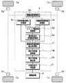
図1に、本発明の一実施形態におけるタイヤ空気圧検出装置の概略構成を示し、この図に基づいてタイヤ空気圧検出装置の説明を行う。
【0016】
タイヤ空気圧検出装置は、各車輪のいずれかのタイヤの空気圧が低下したことを検出するものであり、タイヤ空気圧の低下を検出すると運転者にその旨の警告を行うようになっている。このタイヤ空気圧検出装置は、前輪駆動もしくは後輪駆動の車両に搭載されるが、本実施形態では後輪駆動の車両に搭載された場合を例に挙げて説明する。
【0017】
タイヤ空気圧検出装置は、車両の各車輪1a、1b、1c、1dに対応して設けられた車輪速度検出手段としての車輪速度センサ2a、2b、2c、2dと、各車輪速度センサ2a〜2dからの検出信号が入力される演算処理装置3と、演算処理装置3からの警告信号に基づいてタイヤ空気圧の低下を運転者に警告する警報装置4とを有して構成されている。
【0018】
車輪速度センサ2a〜2dのうち、2つの車輪速度センサ2a、2bは従動輪(右前輪、左前輪)1a、1bにおける車輪速度信号の検出を行い、残る2つの車輪速度センサ2c、2dは駆動輪(右後輪、左後輪)1c、1dにおける車輪速度信号の検出を行う。
【0019】
演算処理装置3は、マイクロコンピュータ等で構成され、車輪速度センサ2a〜2dから入力された検出信号に基づいて各種演算を行う。この演算処理装置3は、以下のように構成されている。
【0020】
演算処理装置3には、車輪速度演算手段としての車輪速度演算部3a、車輪速度偏差値処理部3bが備えられている。車輪速度演算部3aは、車輪速度センサ2a〜2dからの検出信号(例えばパルス信号)に基づいて各車輪1a〜1dの車輪速度の演算が行うものである。車輪速度偏差値処理部3bは、回転状態値演算手段としての車輪速度偏差値演算部、第1車輪速度偏差値記憶部、車輪速度偏差値平均処理部を有して構成されているもので、車輪速度演算部3aでの演算結果に基づいて車輪速度偏差値Dに関する各種処理を行うものである。
【0021】
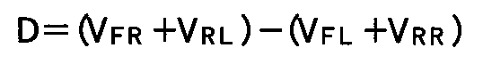
これらの構成においては、まず、車輪速度演算部3aにより車輪速度センサ2a〜2dからの検出信号に基づいて各車輪1a〜1dの車輪速度の演算が行われる。例えば数ms内に入力される各車輪速度センサ2a〜2dからの検出信号の数から各車輪それぞれの車輪速度VFL、VFR、VRL、VRRが演算される。次に、車輪速度が演算されると、この車輪速度に関するデータに基づき、車輪速度偏差値演算部によって数1に示される車輪速度偏差値Dが演算される。
【0022】
【数1】
そして、この演算結果に関するデータが車輪速度偏差値記憶部に備えられたメモリに記憶されると共に、この記憶内容に基づき車輪速度偏差値平均処理部にて車輪速度偏差値Dの平均値DAVEが求められる。なお、車輪速度偏差値Dの平均値DAVEは、次式のように示され、n0個の車輪速度偏差値Dを平均化したものに相当する。
【0024】
【数2】
また、演算処理装置3には、前後車輪速度比処理部3cが備えられている。この前後車輪速度比処理部3cは、前後車輪速度比演算部、前後車輪速度比記憶部、前後車輪速度比平均処理部を有して構成されている。この前後車輪速度比処理部3cでは、車輪速度演算部3aから送られる車輪速度に関するデータに基づき、前後車輪速度比演算部にて数3に示される前後車輪速度比βが演算される。
【0026】
【数3】
その後、この演算結果に関するデータが前後車輪速度比記憶部に備えられたメモリに記憶され、この記憶内容に基づいて前後車輪速度比平均処理部が前後車輪速度比βの平均値βAVEを求めるようになっている。なお、前後車輪速度比βの平均値βAVEは、次式のように示され、n0個の前後車輪速度比βを平均化したものに相当する。
【0028】
【数4】
また、演算処理装置3には、スリップ偏差値演算部3d、理想的走行状態値演算部3e、車輪速度偏差値補正処理部3fが備えられている。
【0030】
スリップ偏差値演算部3dでは、車輪速度偏差値処理部3b内の車輪速度偏差値演算部によって演算された車輪速度偏差値Dと、前後車輪速度比処理部3c内の前後車輪速度比演算部によって演算された前後車輪速度比βとに基づいて、スリップ偏差値Aを演算する。このスリップ偏差値Aとは、前後車輪速度比βに対する車輪速度偏差値Dの変化量(ΔD/Δβ)に相当し、n0個の車輪速度偏差値Dと前後車輪速度比βとをもとに最小2乗法を用いて演算される。
【0031】
理想走行状態値演算部3eでは、スリップ偏差値演算部3dでの演算結果に基づいて理想走行状態値βidを演算する。この理想走行状態値βidとは、補正基準となるスリップのない理想的な走行状態での前後車輪速度比βに相当し、スリップ偏差値Aの1次又はそれ以上の関数として演算される。すなわち、理想走行状態値βidは、βid=F(A)で表され、例えばスリップ偏差値Aの1次の関数となる場合には、βid=1−Coef×|A|で表される。ただし、Coefは定数である。
【0032】
車輪速度偏差値補正処理部3fは、車輪速度偏差値補正部、第2車輪速度偏差値記憶部を有して構成されている。車輪速度偏差値補正部では、車輪速度偏差値処理部3b内の車輪速度偏差値平均処理部で演算された車輪速度偏差値平均値DAVEと、前後車輪速度比処理部3c内の前後車輪速度比平均処理部で演算された前後車輪速度比平均値βAVEと、スリップ偏差値演算部3dで演算されたスリップ偏差値Aと、理想的走行状態値演算部3eで演算された理想走行状態値βidとに基づいて、補正後車輪速度偏差値D′AVEを演算する。補正後車輪速度偏差値D′AVEとは、理想的な走行状態における車輪速度偏差値Dに相当する。具体的には、補正後車輪速度偏差値D′AVEを次式のように求めている。
【0033】
【数5】
![]()
そして、第2車輪速度偏差値記憶部では、車輪速度偏差値補正部で演算された補正後車輪速度偏差値D′AVEのうち、基準値D′AVEstdをメモリに記憶する。この基準値D′AVEstdとは、空気圧判定の基準となる4輪同圧時の補正後車輪速度偏差値D′AVEであり、演算処理装置3の起動後、最初に演算された車輪速度偏差値Dと前後車輪速度比βとから求められた車輪速度偏差値平均値DAVE、前後車輪速度比平均値βAVE、スリップ偏差値A、理想走行状態値βidから演算されたものに相当する。
【0035】
さらに、演算処理装置3には、差圧判定値演算部3g、差圧判定値補正部3h、空気圧低下判定部3iとが備えられている。差圧判定値演算部3gでは、車輪速度偏差値補正処理部3f内の第2車輪速度偏差値記憶部に記憶された基準値D′AVEstdと、車輪速度偏差値補正部で求められた補正後車輪速度偏差値D′AVEとに基づいて差圧判定値ΔD′AVEを求める。この差圧判定値ΔD′AVEは、基準値D′AVEstdと車輪速度偏差値D′AVEとの差分(ΔD′AVE=D′AVEstd−D′AVE)に相当し、本実施形態ではこの差圧判定値ΔD′AVEが空気圧の低下量評価の判定値に用いられる。
【0036】
差圧判定値補正部3hでは、差圧判定値演算部3gで求められた差圧判定値ΔD′AVEの補正を行う。この差圧判定値補正部3hがトレッドリフト補正処理手段に相当する。ここでの補正は、基本的には上述した従来公報(特開平7−125512号公報)と同様の方法で行っている。以下、この補正方法を説明する。
【0037】
この補正は車速Vの2乗と差圧判定値ΔD′AVEとの関係式に基づいて行われる。まず、この関係式の設定について説明する。車速Vは、車輪速度演算部3aでの演算結果に基づき演算され、車輪速度VFL、VFR、VRL、VRRの平均値となる平均車輪速度VAVEに相当する。この平均車輪速度VAVEは、例えば各車輪1a〜1dすべての車輪速度VFL、VFR、VRL、VRRの総和を4(車輪数)で割った値としても良いし、1つの車輪のタイヤ空気圧が低下していることを考慮して、各車輪速度VFL、VFR、VRL、VRRのうちの小さい方から3輪分の和を3で割った値としても良い。
【0038】
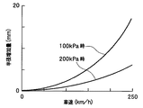
一方、車速Vに対する差圧判定値ΔD′AVEの相関は、まず、4輪のうちのいずれか1つのタイヤの空気圧を規定値からある程度(例えば30%)低下させたのち、車速Vに応じて差圧判定値ΔD′AVEがどの程度変化するかを実測することによって求められる。このような条件下において、ある速度で車両を走行させ、その走行中における差圧判定値ΔD′AVEを求める。これを、例えば20km/h〜180km/hの速度範囲を10km/h毎に区分して複数回行ったのち、各車速V毎に求めた差圧判定値ΔD′AVEの平均値を求める。このような動作をすべてのタイヤに対して行い、各タイヤそれぞれ、各車速V毎に想定される差圧判定値ΔD′AVEを求める。
【0039】
この後、区分した速度範囲のうち、任意の速度(例えば120km/h)を基準速度V0として設定し、その基準速度V0に対する各車速Vの比の2乗値X(=(V/V0)2)を横軸、基準速度における差圧判定値ΔD′AVEの平均値に対する各速度Vにおける差圧判定値ΔD′AVEの平均値の比Yを縦軸にとってグラフを描く。
【0040】
このようにしてグラフを描いたのち、最小2乗法による回帰演算を行うと、例えば右下がりの直線となることから、XとYとの相関が、例えばY=−aX+b(ただし、a、bは任意の定数)のような一次式として求められる。そして、このXとYとの相関を示す関係式をメモリに記憶させる。これにより、まず車速Vの2乗に対する差圧判定値ΔD′AVEの相関関係が設定される。
【0041】
次に、設定された車速Vの2乗に対する差圧判定値ΔD′AVEの関係式に基づき、実走行中に差圧判定値演算部3gで求められた差圧判定値ΔD′AVEの補正を行い、補正後差圧判定値ΔD′′AVEを求める。すなわち、次式のように補正する。ただし、数6の示されるr(V)は、上記Yの逆数の相当する。
【0042】
【数6】
ΔD′′AVE=ΔD′AVE×r(V)
このようにして、差圧判定値ΔD′AVEに対するトレッドリフト補正を行っている。ただし、後述するように(ステップS112参照)、この補正は、補正対象となる差圧判定値ΔD′AVEが所定のしきい値Cshよりも大きくなる場合に行われ、小さい場合には行われないようになっている。
【0043】
そして、空気圧低下判定部3iでは、補正後差圧判定値ΔD′′AVEの絶対値|ΔD′′AVE|と予め設定されたスレッショルド値Dshとを比較することによって、空気圧判定を行う。具体的には、絶対値|ΔD′′AVE|の方がスレッショルド値D′′shよりも大きければ、タイヤ空気圧が低下している旨の警告信号を警報装置4に送るようになっている。
【0044】
そして、警報装置4は、このタイヤ空気圧が低下している旨の警告信号が入力されると、例えば車室内に備えられた警告ランプを点灯させること等により、運転者に対してタイヤ空気圧が低下したことを警告するようになっている。
【0045】
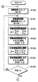
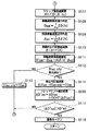
次に、図2、図3に、上記構成のタイヤ空気圧検出装置によるタイヤ空気圧判定処理のフローチャートを示し、これらの図に基づいてタイヤ空気圧判定処理の詳細を説明する。
【0046】
まず、ステップS100では、演算回数カウントNをN=0にリセットする。そして、ステップS101では、車輪速度センサ2a〜2dからの検出信号に基づく車輪速度演算処理として、車輪速度演算部3aで各車輪それぞれの車輪速度VFL、VFR、VRL、VRRの演算を行ったのち、車輪速度の演算回数Nをインクリメントする。この処理は、例えば数秒間の車輪速度パルスをもとに、数秒毎の車輪速度の平均値を各車輪毎に演算することで行う。
【0047】
続く、ステップS102では、車輪速度偏差値演算処理として、車輪速度偏差値処理部3b内の車輪速度偏差値演算部で車輪速度偏差値Dを演算する。この車輪速度偏差値DはステップS101で求められた各車輪速度を上記数1に代入することにより求められる。そして、ステップS103で、第1車輪速度偏差値記憶部のメモリに、今まで記憶させてきた車輪速度偏差値D(N)の一つとして、今回演算された車輪速度偏差値Dを記憶させる。なお、D(N)はn0個分の車輪速度偏差値Dの配列で、車輪速度偏差値Dをn0個格納し、演算回数Nと一致する場所に車輪速度偏差値Dを記憶するようになっている。そして、n0個の車輪速度偏差値Dが格納された後において、例えば後述するカウンタリセット処理(ステップS100)で演算回数Nが0にリセットされると、演算回数Nに応じた場所に記憶された車輪速度偏差値Dが新しく演算された車輪速度偏差値Dに適宜更新されるようになっている。
【0048】
続く、ステップS104では、前後車輪速度比演算処理として、前後車輪速度比処理部3c内の前後車輪速度比演算部で前後車輪速度比βを演算する。この前後車輪速度比βもステップS101で求められた各車輪速度を上記数2に代入することにより求められる。そして、ステップS105で、前後車輪速度比記憶部のメモリに、今まで記憶させてきた前後車輪速度比β(N)の一つとして、今回演算された前後車輪速度比βを記憶させる。なお、β(N)はn0個分の前後車輪速度比βの配列で、前後車輪速度比βをn0個格納し、演算回数Nと一致する場所に前後車輪速度比βを記憶するようになっている。そして、n0個の前後車輪速度比βが格納された後においては、上記したβ(N)と同様に、適宜、新しく演算された前後車輪速度比βへと更新されるようになっている。
【0049】
この後、ステップS106で、演算回数Nがn0以上であるか否かを判定する。そして、肯定判定されればn0個分の車輪速度偏差値Dや前後車輪速度比βが記憶されたものとしてステップS107に進み、否定判定されればステップS101に戻る。
【0050】
続く、ステップS107では、スリップ偏差値演算処理として、スリップ偏差値演算部3dでスリップ偏差値Aを求める。すなわち、最小2乗法を用いてn0個分の前後車輪速度比βと車輪速度偏差値Dとの関係を一次関数に回帰した回帰直線を導出し、この回帰直線の傾きからスリップ偏差値Aを求める。このスリップ偏差値Aは、車輪速度偏差値Dの前後車輪速度比βに対する依存性を表す。
【0051】
続く、ステップS108では、車輪速度偏差値平均化処理として、車輪速度偏差値処理部3b内の車輪速度偏差値平均処理部で車輪速度偏差値Dの平均値DAVEを演算する。この平均値DAVEは、ステップS103で記憶されたn0個分の車輪速度偏差値Dを上記数3に代入することにより求められる。
【0052】
続く、ステップS109では、前後車輪速度比平均処理として、前後車輪速度比処理部3c内の前後車輪速度比平均処理部で前後車輪速度比βの平均値βAVEを演算する。この平均値βAVEは、ステップS105で記憶されたn0個分の前後車輪速度比βを上記数4に代入することにより求められる。
【0053】
続く、ステップS110では、理想的走行状態値演算処理として、理想的走行状態値演算部3eで理想的走行状態値βidを演算する。この理想的走行状態値βidは、ステップS110で演算されたスリップ偏差値Aに関する1次もしくはそれ以上の関数から求められる。
【0054】
続く、ステップS111では、車輪速度偏差値補正処理として、車輪速度偏差値補正処理部3f内の車輪速度偏差値補正部で、ステップS107〜S110で求められたスリップ偏差値A、車輪速度偏差値平均値DAVE、前後車輪速度比平均値βAVE、および理想走行状態値βidを、上記数5に代入することにより補正後車輪速度偏差値D′AVEを求める。
【0055】
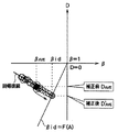
図4に、補正後車輪速度偏差値D′AVEと、この補正後車輪速度偏差値D′AVEの導出に用いるスリップ偏差値A、理想的走行状態値βid、車輪速度偏差値平均値DAVE、および前後車輪速度比平均値βAVEの相関関係を示し、これらの関係について具体的に説明する。
【0056】
図4は、駆動輪1c、1dのいずれか一方、ここでは左後輪のタイヤ空気圧が低下した時における車輪速度偏差値Dと前後車輪速度比βとの相関関係を示している。この図中、白丸が、演算されたn0個分の車輪速度偏差値Dと前後車輪速度比βとの関係を示し、黒丸が車輪速度偏差値平均値DAVEと前後車輪速度比平均値βAVEとの関係を示している。
【0057】
駆動輪1c、1dの一方である左後輪のタイヤ空気圧が低下すると、左後輪における車輪速度VRLが増加するため、タイヤ空気圧の低下に伴って前後車輪速度比βが1より低下する。そして、理想的な走行状態においては、理想的走行状態値βidがβid=F(A)の関係となる。このため、本実施形態のステップS113に示したように、スリップ偏差値Aに基づき、βid=F(A)の関係から理想的走行状態値βidが求められる。
【0058】
一方、ステップS107に示したように、最小2乗法を用いてn0個分の前後車輪速度比βと車輪速度偏差値Dとの関係を一次関数に回帰した回帰直線を導出することができる。
【0059】
従って、ステップS111で示したように、導出した回帰直線と理想的走行状態値βid=F(A)との交点を求めることにより、駆動輪1c、1dの空気圧低下時の理想的な走行状態における車輪速度偏差値D、すなわち補正後車輪速度偏差値D′AVEを求めることができる。
【0060】
このようにして、駆動輪1c、1dの空気圧低下時における理想的な走行状態での車輪速度偏差値Dである補正後車輪速度偏差値D′AVEを正確に求めることができる。
【0061】
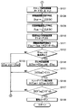
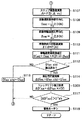
そして、ステップS112で基準値D′AVEstdがすでに検出済みであるか否かを判定する。これは、車輪速度偏差値補正処理部3f内の第2車輪速度偏差値記憶部のメモリに基準値D′AVEstdが記憶されているか否かによって判定される。そして、今回演算された補正後車輪速度偏差値D′AVEが、演算処理装置3の起動後最初に求められたものであれば、基準値D′AVEstdが記憶されていないため、ステップS113に進んで今回演算されたD′AVEを基準値D′AVEstdとしてメモリに記憶し、ステップS100に戻る。また、今回演算された補正後車輪速度偏差値D′AVEが、最初に求められたものでなければステップS114に進む。
【0062】
続く、ステップS114では、差圧判定値演算処理として、差圧判定値演算部3gで基準値D′AVEstdと補正後車輪速度偏差値D′AVEとの差分となる差圧判定値ΔD′AVEを求める。
【0063】
この後、ステップS115に進み、差圧判定値ΔD′AVEが所定のしきい値Cthよりも大きいか否かを判定する。つまり、差圧判定値ΔD′AVEがあまり大きくない場合は、タイヤ空気圧低下量が小さく、トレッドリフトの影響が少ない。このため、このような場合にまでトレッドリフト補正処理を行うと、差圧判定値ΔD′AVEのバラツキをかえって増大させてしまう。従って、このステップで肯定判定されればステップS116に進んでトレッドリフト補正処理を行い、否定判定されればステップ100に戻る。
【0064】
続く、ステップS116では、トレッドリフト補正処理として、差圧判定値補正部3hで差圧判定値ΔD′AVEの補正を行う。具体的には、上述したように、予め設定された車速Vの2乗と差圧判定値ΔD′AVEとの関係式(数5参照)を利用して、差圧判定値ΔD′AVEの補正を行い、補正後差圧判定値ΔD′′AVEを求めている。
【0065】
そして、ステップS117で、補正後差圧判定値ΔD′′AVEの絶対値|ΔD′′AVE|と予め設定されたスレッショルド値D′′shとを大小比較し、絶対値|ΔD′′AVE|がスレッショルド値D′′shよりも大きいか否かを判定する。
【0066】
これにより、肯定判定されるとステップS118に進み、タイヤ空気圧が低下しているとして、その旨の警告信号を警報装置4に送り、否定判定されるとそのまま処理を終了し、ステップS100に戻る。以上の処理により、各車輪1a〜1dにおけるタイヤ空気圧が低下しているか否かが判定できる。
【0067】
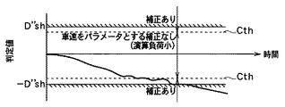
以上説明した処理を実行した場合における差圧判定値ΔD′AVEの変化の一例を図示すると、図5のように示される。この図に示されるように、本実施形態に示すタイヤ空気圧検出装置においては、差圧判定値ΔD′AVEが所定のしきい値Cthよりも小さくなる場合には、トレッドリフト補正を行わず、大きくなる場合についてのみ、トレッドリフト補正を行うようにしている。つまり、真にトレッドリフトの影響が大きく、補正が必要とされる場合についてのみ、差圧判定値ΔD′AVEを補正している。このため、トレッドリフトの影響が少ないにも関わらず補正されることによって発生する差圧判定値ΔD′AVEのバラツキを防止できる。
【0068】
そして、トレッドリフトの影響が大きくなる場合には的確に差圧判定値ΔD′AVEの補正を行っているため、トレッドリフトの影響によるタイヤ動半径の増大によって、タイヤ空気圧が低下した車輪の車輪速度と低下していない車輪の車輪速度とが同等になり、車速が高くなるに連れてタイヤ空気圧低下がない側に差圧判定値が偏ることを防止し、的確な差圧判定値を求めることができる。このため、タイヤ空気圧の検出精度の低下も防止できる。
【0069】
また、基準値D′AVEstdが設定されるまで、つまり初期化モードの際にはトレッドリフト補正処理が成されないようになっている。このため、4つの車輪1a〜1dのタイヤ空気圧が同圧である場合の基準値を検出するときには差圧判定値ΔD′AVEの補正が禁止される。このため、的確に初期モード設定を行うことができる。
【0070】
(第2実施形態)
本実施形態では、第1実施形態とは異なる方法で差圧判定値の補正を行う場合を説明する。なお、本実施形態におけるタイヤ空気圧検出装置の基本構成は第1実施形態と同様であり、差圧判定値補正処理部3hで行われる処理のみが異なるため、ここでは本実施形態でも差圧判定値補正処理部3hの役割についてのみ説明する。
【0071】
本実施形態における差圧判定値補正処理部3hでは、まず、第1実施形態と同様の方法により、車速Vの2乗と差圧判定値との関係式が求められる。次に、求められた関係式をメモリに記憶させる。
【0072】
次に、設定された車速Vの2乗に対する差圧判定値ΔD′AVEの関係式に基づき、実走行中に差圧判定値演算部で求められた差圧判定値ΔD′AVEの補正を行う。このとき、第1実施形態とは異なり、差圧判定値ΔD′AVEが所定のしきい値Cthを超えているか否かに関わらず、求められたすべての差圧判定値ΔD′AVEに対して補正を行う。ただし、差圧判定値ΔD′AVEの補正割合を差圧判定値ΔD′AVEの偏差量(大きさ)に応じて調整し、差圧判定値ΔD′AVEの偏差量が大きい程、差圧判定値ΔD′AVEの補正割合を大きく設定する。例えば、本来の差圧判定値ΔD′AVEの補正が第1実施形態で示した数6で表されるのであれば、本実施形態における差圧判定値ΔD′AVEの補正は本来の補正量に対して、(差圧判定値ΔD′AVEの偏差量/しきい値Cth)×100〔%〕の補正割合を掛け合わせるようにしたもの、すなわち次式のようにして差圧判定値ΔD′AVEを補正している。
【0073】
【数7】
![]()
次に、図6に、本実施形態のタイヤ空気圧検出装置によるタイヤ空気圧判定処理のフローチャートを示し、これらの図に基づいてタイヤ空気圧判定処理の詳細を説明する。ただし、本実施形態のタイヤ空気圧判定処理のフローチャートは、第1実施形態における図2、図3とほぼ同様で、図3に示すステップS115、S116を変更したものであるため、変更部分のみ示すものとする。
【0075】
まず、第1実施形態と同様にステップS114まで進み、差圧判定値ΔD′AV Eを演算する。そして、ステップS200に進み、差圧判定値ΔD′AVEの補正を行う。この差圧判定値ΔD′AVEの補正は上述したように行われる。このようにして差圧判定値ΔD′AVEが補正されたのち、ステップS117以降に進み、第1実施形態と同様の処理を行う。
【0076】
このように、差圧判定値ΔD′AVEの偏差量に応じて補正割合を調整することで、トレッドリフトの影響が少ない場合には補正割合を小さくできると共に、トレッドリフトの影響が大きい場合には補正割合を大きくでき、的確な差圧判定値ΔD′AVEの補正を行うことができる。これにより、的確にタイヤ空気圧検出を行うことができる。
【0077】
(第3実施形態)
上記第1実施形態では、差圧判定値ΔD′AVEが所定のしきい値Cthよりも大きい場合にトレッドリフト補正を行い、第2実施形態では、差圧判定値ΔD′AVEの大きさに合わせてトレッドリフト補正の補正割合を変化させるようにしているが、これらの処理を行わなくても、初期化モード時に差圧判定値ΔD′AVEをトレッドリフト補正しないようにするだけでもよい。この場合のタイヤ空気圧検出処理のフローチャートは図7のように示される。なお、この場合においても第1実施形態における図2、図3とほぼ同様であり、図3に示すステップS115を無くしたものであるため、変更部分のみ示してある。
【0078】
この図のステップS300で示されるように、差圧判定値ΔD′AVEが常に第1実施形態におけるステップS116と同様の処理により、差圧判定値ΔD′AVEが補正される。しかしながら、この場合においてもステップS112に示されるように、初期化モードの際にはトレッドリフト補正が行われない様にしているため、4つの車輪1a〜1dのタイヤ空気圧が同圧である場合の基準値を検出するときには差圧判定値ΔD′AVEの補正が禁止される。このため、的確に初期モード設定を行うことができる。
【0079】
(他の実施形態)
上記各実施形態で示した差圧判定値の補正式は一例であり、この他の補正式を用いた補正であってもよい。すなわち、補正式はタイヤ空気圧の低下に伴って変化するため、タイヤ空気圧の低下に応じて変更するようにしてもよい。
【0080】
また、上記各実施形態では、タイヤ空気圧低下の検出に用いる判定値として、差圧判定値ΔD′AVEを用いる場合について説明しているが、他の判定値(例えば車輪速度偏差値D)を用いる場合であっても上記各実施形態を適用することができる。
【0081】
また、上記実施形態では、後輪駆動の車両に本発明の一実施形態を適用したものを例に挙げて説明したが、前輪駆動の車両に適用してもよい。この場合には、駆動輪のタイヤ空気圧低下に伴って、理想的走行状態値βidが1より大きくなるという関係になる。
【0082】
また、上記説明においては、回転状態値として数1に示される車輪速度偏差値Dを用いているが、他のものを用いても良い。すなわち、回転状態値とは、車両旋回に起因して発生し得る左右輪間の車輪速度の偏りが打ち消されるように、各車輪1a〜1dの車輪速度を関係づけた値であればよく、数1で表されるものの他、例えば以下に表すものがある。
【0083】
【数8】
【数9】
![]()
【数10】
これらの関係式はすべて、車両旋回時に同様の車輪速度の偏りが発生しうる左前後輪間と右前後輪間とのそれぞれの差分をとることで、車両旋回に起因して発生する左右前輪間および左右後輪間の車輪速度の偏りが打ち消されるように、各車輪1a〜1dの車輪速度を関係づけたものである。
【0087】
また、上記実施形態で説明したように、車輪速度偏差値Dが所定のしきい値を超える時にタイヤ空気圧低下を警告するようなシステムである場合には、スリップ偏差値(傾き)Aが小さいときに、スリップによる車輪速度偏差値Dの補正を行わなくても良い。これは、後輪(駆動輪)減圧時の場合、スリップ偏差値Aが小さい時は、車輪速度偏差値Dがしきい値を超える可能性がないことから、多少の誤差があったとしても問題がないし、また、前輪(転動輪)減圧時はいかなる場合でも傾きAがほぼんど零になることから、スリップによる車輪速度偏差値Dの補正は不要であるためである。従って、スリップ偏差値Aが小さい場合を補正対象から除くことにより、後輪減圧時のうちの補正の必要性に乏しい場合、及び前輪減圧時を補正対象から除外することが可能である。
【0088】
また、上記各実施形態では、車輪速度偏差値Dの平均値DAVEを求めた後に、平均値DAVEをβid=F(A)で表される曲線上に投影することによって補正後車輪速度偏差値D′AVEを求めるようにしているが、車輪速度偏差値Dのそれぞれをβid=F(A)で表される曲線上に投影した後、それらの平均値を採るようにしても良い。
【0089】
また、上記各実施形態では、演算回数Nがn0となるごとに、それまでにデータとして記憶されたn0個分の車輪速度偏差値Dや前後車輪速度比βから、それらの平均値DAVEや平均値βAVEを求め、差圧判定値ΔD′AVEの絶対値|ΔD′AVE|を求めるようにしている。しかしながら、このような場合にはn0個分のデータが蓄積される間、タイヤ空気圧判定が行えない。このため、車輪速度偏差値記憶部や前後車輪速度比記憶部で、最も古くに記憶された車輪速度偏差値Dや前後車輪速度比βが新しく演算された車輪速度偏差値Dや前後車輪速度比βに適宜更新されるようにし、更新される毎に平均値DAVEや平均値βAVEを求めるようにするという移動平均とすることで、短時間毎にタイヤ空気圧判定が行えるようにできる
なお、上記実施形態では、理想走行状態値βid=F(A)に基づいて回転状態値(車輪速度偏差値D)を補正する場合を例に挙げたが、他の回転状態値の補正方法を採用したものにおいて、各実施形態で示すトレッドリフト補正処理を施すことも可能である。
【図面の簡単な説明】
【図1】本発明の第1実施形態におけるタイヤ空気圧検出装置の概略構成を示す図である。
【図2】図1に示すタイヤ空気圧検出装置が実行する制御のフローチャートである。
【図3】図2に続くタイヤ空気圧検出装置が実行する制御のフローチャートである。
【図4】図1に示すタイヤ空気圧検出装置における補正前の車輪速度偏差値平均値DAVEと補正後車輪速度偏差値D′AVEとの関係を示した図である。
【図5】図2、図3に示す処理を実行した場合における差圧判定値ΔD′AVEの変化の一例を示したタイミングチャートである。
【図6】本発明の第2実施形態におけるタイヤ空気圧検出装置が実行する制御のフローチャートである。
【図7】本発明の第3実施形態におけるタイヤ空気圧検出装置が実行する制御のフローチャートである。
【図8】車速と動荷重半径増加量との関係を示した図である。
【符号の説明】
1a〜1d…車輪、2a〜2d…車輪速度センサ、3…演算処理装置、3a…車輪速度演算部、3b…車輪速度偏差値処理部、3c…前後車輪速度比処理部、3d…スリップ偏差値演算部、3e…理想的走行状態値演算部、3f…車輪速度偏差値補正処理部、3g…差圧判定値演算部、3h…差圧判定値補正部、3i…空気圧低下判定部、4…警報装置。[0001]
BACKGROUND OF THE INVENTION
The present invention relates to a tire air pressure detection device that detects a state of tire air pressure in a vehicle.
[0002]
[Prior art]
Conventionally, as a tire pressure detecting device capable of accurately detecting tire pressure in consideration of so-called tread lift, there is one disclosed in JP-A-7-125512. The tread lift is a phenomenon in which, when the tire radius increases due to centrifugal force, the dynamic load radius of a tire with reduced air pressure approaches that of a tire with no decrease. When the tire moving radius increases due to the influence of the tread lift, the wheel speed of the wheel with the decreased tire pressure becomes equal to the wheel speed of the unreduced wheel. Since the value is obtained erroneously and the judgment value changes so as to deviate toward the side where the tire air pressure does not decrease as the vehicle speed increases, the tire air pressure is not accurately detected.
[0003]
In the above publication, by performing an experiment using a tire whose air pressure has been reduced in advance, the relationship between the vehicle speed correlated with the centrifugal force and a determination value (for example, a rotational state value) used for tire air pressure detection is stored, and actual running By correcting the determination value according to the vehicle speed at the time, the influence of the tread lift is corrected so that accurate tire pressure detection can be performed.
[0004]
[Problems to be solved by the invention]
However, the degree of influence of the tread lift described above also varies depending on the tire air pressure. For example, the tire air pressure and the influence of the tread lift are illustrated as shown in FIG. 8, and the amount of increase in the tire dynamic load radius due to the influence of the tread lift increases as the tire air pressure decreases. The dynamic load radius ΔR of the tire is, for example, ΔR = 10, where P (kgf / cm 2) is the internal pressure of the tire and V (km / h) is the vehicle speed.(-1.97P-1.31)・ V(0.735P-1.147)It is represented by
[0005]
For this reason, when the tire pressure is the same for all four wheels, there is no influence of the tread lift, and only when the tire pressure of any one wheel is significantly reduced. Accordingly, even when the tire pressure is the same for all four wheels, if the correction as shown in the above-mentioned conventional publication is performed, the variation in the determination value is increased and the tire pressure detection accuracy is lowered. .
[0006]
In view of the above points, an object of the present invention is to improve tire pressure detection accuracy by accurately correcting the influence of a tread lift.
[0007]
[Means for Solving the Problems]
In order to achieve the above object, according to the first aspect of the present invention, the determination value (ΔD ′AVE) Exceeds a predetermined threshold value (Cth), and when the determination value exceeds the predetermined threshold value, tread lift correction processing means (3h) for performing tread lift correction on the determination value is provided. The tire pressure drop determining means is characterized in that the tire pressure drop is determined from the determination value after the tread lift correction by the tread lift correction processing means.
[0008]
As described above, when the determination value is smaller than the predetermined threshold value, the tread lift correction is not performed, and the tread lift correction is performed only when the determination value is increased. That is, the determination value is corrected only when the tread lift is truly affected and correction is required. For this reason, it is possible to prevent variations in the judgment value caused by correction even though the influence of the tread lift is small. On the other hand, when the influence of the tread lift becomes large, the determination value is accurately corrected. Therefore, an accurate differential pressure determination value can be obtained, and a decrease in tire air pressure detection accuracy can be prevented.
[0009]
In the second aspect of the present invention, tread lift correction processing means (3h) for performing tread lift correction on the determination value is provided, and the tread lift correction processing means is adapted to tread lift correction according to the magnitude of the determination value. The correction ratio of the correction is adjusted, and the tire pressure drop determination means is characterized in that the tire pressure drop is determined from the determination value after the tread lift correction by the tread lift correction means. For example, as shown in
[0010]
In this way, by changing the correction ratio according to the deviation amount of the judgment value, the correction ratio can be reduced when the influence of the tread lift is small, and the correction ratio can be increased when the influence of the tread lift is large. Thus, the accurate differential pressure determination value can be corrected. Thereby, tire air pressure can be accurately detected.
[0011]
In the invention according to
[0012]
Thus, tread lift correction is not performed in the initialization mode. Therefore, the determination value (reference value ΔD ′) when the tire pressures of the four wheels are the same pressure.AVEWhen detecting std), correction of the judgment value is prohibited. For this reason, the initial mode can be accurately set.
[0013]
For example, as described in claim 6, the determination value includes a value after correction of the rotation state value obtained by the rotation state value correction unit during the initialization mode and a rotation value obtained by the rotation state value correction unit after the initialization mode. The difference between the state value and the corrected value (ΔD ″)AVE) Is used.
[0014]
In addition, the code | symbol in the bracket | parenthesis of each said means shows the correspondence with the specific means as described in embodiment mentioned later.
[0015]
DETAILED DESCRIPTION OF THE INVENTION
(First embodiment)
FIG. 1 shows a schematic configuration of a tire air pressure detection device according to an embodiment of the present invention, and the tire air pressure detection device will be described based on this drawing.
[0016]
The tire air pressure detecting device detects that the air pressure of one of the wheels has decreased, and when a decrease in tire air pressure is detected, a warning to that effect is given to the driver. The tire air pressure detection device is mounted on a front-wheel drive or rear-wheel drive vehicle. In the present embodiment, a case where the tire air-pressure detection device is mounted on a rear-wheel drive vehicle will be described as an example.
[0017]
The tire air pressure detecting device includes
[0018]
Of the wheel speed sensors 2a to 2d, the two
[0019]
The
[0020]
The
[0021]
In these configurations, first, the wheel speed calculation unit 3a calculates the wheel speeds of the wheels 1a to 1d based on the detection signals from the wheel speed sensors 2a to 2d. For example, the wheel speed V of each wheel is determined from the number of detection signals from the wheel speed sensors 2a to 2d input within a few ms.FL, VFR, VRL, VRRIs calculated. Next, when the wheel speed is calculated, the wheel speed deviation value D shown in
[0022]
[Expression 1]
Data relating to the calculation result is stored in a memory provided in the wheel speed deviation value storage unit, and an average value D of the wheel speed deviation values D is determined by the wheel speed deviation value averaging processing unit based on the stored contents.AVEIs required. The average value D of the wheel speed deviation values DAVEIs expressed as:0This corresponds to an average of the individual wheel speed deviation values D.
[0024]
[Expression 2]
In addition, the
[0026]
[Equation 3]
Thereafter, data relating to the calculation result is stored in a memory provided in the front and rear wheel speed ratio storage unit, and based on the stored content, the front and rear wheel speed ratio average processing unit performs an average value β of the front and rear wheel speed ratio β.AVEIs to ask for. Note that the average value β of the front and rear wheel speed ratio βAVEIs expressed as:0This corresponds to an average of the front and rear wheel speed ratio β.
[0028]
[Expression 4]
Further, the
[0030]
In the slip deviation
[0031]
The ideal travel state value calculation unit 3e calculates an ideal travel state value βid based on the calculation result in the slip deviation
[0032]
The wheel speed deviation value correction processing unit 3f includes a wheel speed deviation value correction unit and a second wheel speed deviation value storage unit. In the wheel speed deviation value correction unit, the wheel speed deviation value average value D calculated by the wheel speed deviation value average processing unit in the wheel speed deviation value processing unit 3b.AVEAnd the front and rear wheel speed ratio average value β calculated by the front and rear wheel speed ratio average processing section in the front and rear wheel speed ratio processing section 3c.AVEAnd the corrected wheel speed deviation value D ′ based on the slip deviation value A calculated by the slip deviation
[0033]
[Equation 5]
![]()
Then, in the second wheel speed deviation value storage unit, the corrected wheel speed deviation value D ′ calculated by the wheel speed deviation value correction unit.AVEOf these, the reference value D ′AVEStore std in memory. This reference value D ′AVEstd is a corrected wheel speed deviation value D ′ when the four wheels are at the same pressure, which is a reference for determining air pressure.AVEThe wheel speed deviation average value D obtained from the wheel speed deviation value D calculated first and the front / rear wheel speed ratio β after the start of the
[0035]
Furthermore, the
[0036]
In the differential pressure determination
[0037]
This correction is based on the square of the vehicle speed V and the differential pressure determination value ΔD ′.AVEBased on the relational expression. First, the setting of this relational expression will be described. The vehicle speed V is calculated based on the calculation result in the wheel speed calculation unit 3a.FL, VFR, VRL, VRRThe average wheel speed V that is the average value ofAVEIt corresponds to. This average wheel speed VAVEIs, for example, the wheel speed V of each of the wheels 1a to 1d.FL, VFR, VRL, VRRIt is good also as the value which divided the sum total of 4 by the number of wheels (wheel number), and considering that the tire air pressure of one wheel has fallen, each wheel speed VFL, VFR, VRL, VRRIt is good also as the value which divided the sum for 3 wheels from the smaller one of them by 3.
[0038]
On the other hand, the differential pressure determination value ΔD ′ with respect to the vehicle speed VAVEFirst, after reducing the air pressure of any one of the four wheels from a specified value to some extent (for example, 30%), the differential pressure determination value ΔD ′ according to the vehicle speed VAVEIt is calculated | required by actually measuring how much changes. Under such conditions, the vehicle travels at a certain speed, and the differential pressure determination value ΔD ′ during the travelAVEAsk for. This is performed a plurality of times by dividing the speed range of 20 km / h to 180 km / h, for example, every 10 km / h, and then the differential pressure determination value ΔD ′ obtained for each vehicle speed VAVEFind the average value of. Such an operation is performed on all tires, and the differential pressure judgment value ΔD ′ assumed for each vehicle speed V is determined for each tire.AVEAsk for.
[0039]
Thereafter, an arbitrary speed (for example, 120 km / h) in the divided speed range is set to the reference speed V.0And the square value X of the ratio of each vehicle speed V to the reference speed V0 (= (V / V0)2) On the horizontal axis, the differential pressure judgment value ΔD ′ at the reference speedAVEDifferential pressure judgment value ΔD ′ at each speed V with respect to the average value ofAVEA graph is drawn with the ratio Y of the average values of the vertical axis as the vertical axis.
[0040]
After the graph is drawn in this way, when the regression calculation by the least square method is performed, for example, a straight line descending to the right is obtained. Therefore, the correlation between X and Y is, for example, Y = −aX + b It is obtained as a linear expression such as (arbitrary constant). Then, a relational expression indicating the correlation between X and Y is stored in the memory. Thus, first, the differential pressure determination value ΔD ′ with respect to the square of the vehicle speed VAVECorrelation is set.
[0041]
Next, a differential pressure determination value ΔD ′ with respect to the square of the set vehicle speed VAVEThe differential pressure determination value ΔD ′ obtained by the differential pressure determination
[0042]
[Formula 6]
ΔD ″AVE= ΔD 'AVEXr (V)
In this way, the differential pressure determination value ΔD ′AVETread lift compensation is performed. However, as will be described later (see step S112), this correction is performed using the differential pressure determination value ΔD ′ to be corrected.AVEIs performed when the threshold value is larger than a predetermined threshold value Csh, and is not performed when the threshold value is smaller than the predetermined threshold value Csh.
[0043]
Then, in the air pressure decrease determination unit 3i, the corrected differential pressure determination value ΔD ″AVEAbsolute value | ΔD ″AVEThe air pressure is determined by comparing | with a preset threshold value Dsh. Specifically, the absolute value | ΔD ″AVEIf | is larger than the threshold value D ′ ″ sh, a warning signal indicating that the tire air pressure has decreased is sent to the
[0044]
When the warning signal indicating that the tire pressure is reduced is input to the
[0045]
Next, FIGS. 2 and 3 show flowcharts of tire pressure determination processing by the tire pressure detection device having the above-described configuration, and details of the tire pressure determination processing will be described based on these drawings.
[0046]
First, in step S100, the operation count N is reset to N = 0. In step S101, the wheel speed calculation unit 3a performs wheel speed V for each wheel as wheel speed calculation processing based on detection signals from the wheel speed sensors 2a to 2d.FL, VFR, VRL, VRRAfter the above calculation is performed, the number N of wheel speed calculations is incremented. This processing is performed, for example, by calculating an average value of wheel speeds every several seconds on the basis of wheel speed pulses for several seconds.
[0047]
In step S102, as a wheel speed deviation value calculation process, a wheel speed deviation value D is calculated by a wheel speed deviation value calculation unit in the wheel speed deviation
[0048]
Subsequently, in step S104, the front and rear wheel speed ratio β is calculated by the front and rear wheel speed ratio calculation unit in the front and rear wheel speed
[0049]
Thereafter, in step S106, the number N of operations is n.0It is determined whether it is above. And if an affirmative determination is made, n0The process proceeds to step S107 assuming that the wheel speed deviation value D and the front / rear wheel speed ratio β are stored, and if a negative determination is made, the process returns to step S101.
[0050]
In subsequent step S107, as the slip deviation value calculation process, the slip deviation
[0051]
Subsequently, in step S108, as a wheel speed deviation value averaging process, an average value D of the wheel speed deviation values D in the wheel speed deviation value average processing section in the wheel speed deviation value processing section 3b.AVEIs calculated. This average value DAVEN stored in step S1030It is obtained by substituting the wheel speed deviation value D for each piece into the
[0052]
Subsequently, in step S109, as the front-rear wheel speed ratio average process, the front-rear wheel speed ratio average processing unit in the front-rear wheel speed
[0053]
Subsequently, in step S110, as the ideal traveling state value calculation process, the ideal traveling state value βid is calculated by the ideal traveling state value calculation unit 3e. The ideal running state value βid is obtained from a linear or higher-order function related to the slip deviation value A calculated in step S110.
[0054]
Subsequently, in step S111, as the wheel speed deviation value correction process, the wheel speed deviation value correction unit in the wheel speed deviation value correction processing unit 3f uses the slip deviation value A and the wheel speed deviation value average obtained in steps S107 to S110. Value DAVE, Average wheel speed ratio βAVE, And by substituting the ideal running state value βid into the
[0055]
FIG. 4 shows the corrected wheel speed deviation value D ′.AVEAnd the corrected wheel speed deviation value D ′AVESlip deviation value A, ideal running state value βid, wheel speed deviation average value DAVE, And front and rear wheel speed ratio average value βAVEThese correlations are shown, and these relationships will be specifically described.
[0056]
FIG. 4 shows a correlation between the wheel speed deviation value D and the front and rear wheel speed ratio β when the tire air pressure of one of the
[0057]
When the tire air pressure of the left rear wheel, which is one of the
[0058]
On the other hand, as shown in step S107, the least square method is used to make n0A regression line obtained by regressing the relationship between the front and rear wheel speed ratio β and the wheel speed deviation value D into a linear function can be derived.
[0059]
Therefore, as shown in step S111, by obtaining the intersection of the derived regression line and the ideal running state value βid = F (A), in the ideal running state when the air pressure of the
[0060]
In this way, the corrected wheel speed deviation value D ′, which is the wheel speed deviation value D in the ideal running state when the air pressure of the
[0061]
In step S112, the reference value D 'AVEIt is determined whether std has already been detected. The reference value D ′ is stored in the memory of the second wheel speed deviation value storage unit in the wheel speed deviation value correction processing unit 3f.AVEThe determination is made based on whether std is stored. And the corrected wheel speed deviation value D ′ calculated this timeAVEIs the first value obtained after activation of the
[0062]
Subsequently, in step S114, as the differential pressure determination value calculation process, the differential pressure determination
[0063]
After this, the process proceeds to step S115, where the differential pressure determination value ΔD ′AVEIs greater than a predetermined threshold value Cth. That is, the differential pressure determination value ΔD ′AVEWhen is not so large, the amount of decrease in tire air pressure is small and the influence of the tread lift is small. Therefore, if the tread lift correction process is performed up to such a case, the differential pressure determination value ΔD ′AVEIt will increase the variation of the. Therefore, if an affirmative determination is made in this step, the process proceeds to step S116 to perform a tread lift correction process, and if a negative determination is made, the process returns to step 100.
[0064]
Subsequently, in step S116, as the tread lift correction process, the differential pressure determination
[0065]
In step S117, the corrected differential pressure determination value ΔD ″AVEAbsolute value | ΔD ″AVE| Is compared with a preset threshold value D ″ sh, and the absolute value | ΔD ″AVEIt is determined whether or not | is larger than the threshold value D ″ sh.
[0066]
As a result, if an affirmative determination is made, the process proceeds to step S118. If the tire air pressure has decreased, a warning signal to that effect is sent to the
[0067]
Differential pressure determination value ΔD ′ when the processing described above is executedAVEAn example of this change is shown in FIG. As shown in this figure, in the tire air pressure detecting device shown in the present embodiment, the differential pressure determination value ΔD ′AVEWhen is smaller than the predetermined threshold value Cth, tread lift correction is not performed, and only when the tread lift is increased, tread lift correction is performed. In other words, only when the influence of the tread lift is really great and correction is required, the differential pressure determination value ΔD ′AVEIs corrected. For this reason, the differential pressure determination value ΔD ′ generated by the correction even though the influence of the tread lift is small.AVECan be prevented.
[0068]
When the influence of the tread lift becomes large, the differential pressure determination value ΔD ′ is accurately determined.AVEAs a result, the wheel speed of a wheel with reduced tire pressure becomes equal to the wheel speed of a non-reduced wheel due to an increase in tire radius due to the tread lift, and as the vehicle speed increases. Thus, it is possible to prevent the differential pressure determination value from being biased toward the side where there is no decrease in tire air pressure, and to obtain an accurate differential pressure determination value. For this reason, it is possible to prevent a decrease in tire air pressure detection accuracy.
[0069]
Reference value D ′AVEThe tread lift correction processing is not performed until std is set, that is, in the initialization mode. Therefore, when detecting the reference value when the tire pressures of the four wheels 1a to 1d are the same pressure, the differential pressure determination value ΔD ′AVECorrection is prohibited. For this reason, the initial mode can be accurately set.
[0070]
(Second Embodiment)
In the present embodiment, a case where the differential pressure determination value is corrected by a method different from the first embodiment will be described. Note that the basic configuration of the tire air pressure detection device in the present embodiment is the same as that in the first embodiment, and only the processing performed by the differential pressure determination value
[0071]
In the differential pressure determination value
[0072]
Next, a differential pressure determination value ΔD ′ with respect to the square of the set vehicle speed VAVEThe differential pressure determination value ΔD ′ obtained by the differential pressure determination value calculation unit during actual traveling based onAVEPerform the correction. At this time, unlike the first embodiment, the differential pressure determination value ΔD ′AVERegardless of whether or not exceeds a predetermined threshold value Cth, all the obtained differential pressure determination values ΔD ′AVEIs corrected. However, the differential pressure judgment value ΔD ′AVEIs the differential pressure determination value ΔD ′.AVEIs adjusted according to the deviation amount (size) of the differential pressure judgment value ΔD ′AVEThe greater the deviation amount, the differential pressure judgment value ΔD ′AVESet a large correction ratio. For example, the original differential pressure determination value ΔD ′AVEIs expressed by Equation 6 shown in the first embodiment, the differential pressure determination value ΔD ′ in the present embodiment.AVEThe correction of (differential pressure judgment value ΔD ′ with respect to the original correction amount)AVEDeviation amount / threshold value Cth) × 100 [%] correction ratio, that is, differential pressure judgment value ΔD ′AVEIs corrected.
[0073]
[Expression 7]
![]()
Next, FIG. 6 shows a flowchart of a tire air pressure determination process by the tire air pressure detection device of the present embodiment, and details of the tire air pressure determination process will be described based on these drawings. However, the flowchart of the tire air pressure determination process of the present embodiment is almost the same as that in FIGS. 2 and 3 in the first embodiment, and steps S115 and S116 shown in FIG. 3 are changed. And
[0075]
First, the process proceeds to step S114 as in the first embodiment, and the differential pressure determination value ΔD ′.AV EIs calculated. Then, the process proceeds to step S200, and the differential pressure determination value ΔD ′AVEPerform the correction. This differential pressure judgment value ΔD ′AVEThis correction is performed as described above. In this way, the differential pressure determination value ΔD ′AVEIs corrected, the process proceeds to step S117 and subsequent steps, and the same processing as in the first embodiment is performed.
[0076]
Thus, the differential pressure determination value ΔD ′AVEBy adjusting the correction ratio according to the amount of deviation, the correction ratio can be reduced when the influence of the tread lift is small, and the correction ratio can be increased when the influence of the tread lift is large. Value ΔD 'AVECan be corrected. Thereby, tire air pressure can be accurately detected.
[0077]
(Third embodiment)
In the first embodiment, the differential pressure determination value ΔD ′AVEIs larger than the predetermined threshold value Cth, tread lift correction is performed. In the second embodiment, the differential pressure determination value ΔD ′AVEThe correction ratio of the tread lift correction is changed in accordance with the magnitude of the pressure difference, but even if these processes are not performed, the differential pressure determination value ΔD ′ is obtained in the initialization mode.AVEIt is also possible not to correct the tread lift. A flowchart of the tire air pressure detection process in this case is shown in FIG. In this case as well, since it is substantially the same as FIGS. 2 and 3 in the first embodiment and step S115 shown in FIG. 3 is eliminated, only the changed portion is shown.
[0078]
As shown in step S300 of this figure, the differential pressure determination value ΔD ′AVEIs always processed by the same process as step S116 in the first embodiment.AVEIs corrected. However, in this case as well, as shown in step S112, since the tread lift correction is not performed in the initialization mode, the tire pressures of the four wheels 1a to 1d are the same pressure. When the reference value is detected, the differential pressure determination value ΔD ′AVECorrection is prohibited. For this reason, the initial mode can be accurately set.
[0079]
(Other embodiments)
The correction formulas for the differential pressure determination values shown in the above embodiments are merely examples, and correction using other correction formulas may be used. That is, since the correction equation changes with a decrease in tire air pressure, it may be changed according to a decrease in tire air pressure.
[0080]
In each of the above embodiments, the differential pressure determination value ΔD ′ is used as the determination value used for detecting a decrease in tire air pressure.AVEHowever, the above embodiments can be applied even when other determination values (for example, wheel speed deviation value D) are used.
[0081]
Further, in the above-described embodiment, the case where the embodiment of the present invention is applied to a rear-wheel drive vehicle has been described as an example, but the present invention may be applied to a front-wheel drive vehicle. In this case, the ideal running state value βid becomes greater than 1 as the tire air pressure of the drive wheels decreases.
[0082]
Further, in the above description, the wheel speed deviation value D shown in
[0083]
[Equation 8]
[Equation 9]
![]()
[Expression 10]
All of these relational expressions take the difference between the left front and rear wheels and the right front and rear wheels that can cause the same wheel speed deviation when turning the vehicle. In addition, the wheel speeds of the wheels 1a to 1d are related so that the deviation of the wheel speed between the left and right rear wheels is canceled out.
[0087]
Further, as described in the above embodiment, when the system is such that the tire pressure drop is warned when the wheel speed deviation value D exceeds a predetermined threshold value, the slip deviation value (slope) A is small. In addition, it is not necessary to correct the wheel speed deviation value D due to slip. This is because when the rear wheel (drive wheel) is depressurized, if the slip deviation value A is small, the wheel speed deviation value D may not exceed the threshold value. In addition, since the slope A becomes almost zero in any case when the front wheel (rolling wheel) is depressurized, the correction of the wheel speed deviation value D due to the slip is unnecessary. Accordingly, by removing the case where the slip deviation value A is small from the correction target, it is possible to exclude the case where the necessity of correction during the time of rear wheel pressure reduction is low and the time when the front wheel pressure reduction is excluded from the correction target.
[0088]
Further, in each of the above embodiments, the average value D of the wheel speed deviation values DAVEAfter obtaining the average value DAVEIs projected onto the curve represented by βid = F (A), and the corrected wheel speed deviation value D ′AVEHowever, after each of the wheel speed deviation values D is projected onto a curve represented by βid = F (A), an average value thereof may be taken.
[0089]
In each of the above embodiments, the number of operations N is n.0Each time, n stored as data until then0From the wheel speed deviation value D and the front / rear wheel speed ratio β, the average value D thereofAVEAnd mean βAVEThe differential pressure judgment value ΔD ′AVEAbsolute value | ΔD 'AVE| Is requested. However, in such a case, n0The tire pressure cannot be determined while the data for each item is accumulated. For this reason, the wheel speed deviation value D and the front and rear wheel speed ratio newly calculated from the wheel speed deviation value D and the front and rear wheel speed ratio β stored the oldest in the wheel speed deviation value storage unit and the front and rear wheel speed ratio storage unit. β is updated as appropriate, and the average value D is updated every time it is updated.AVEAnd mean βAVEThe tire pressure can be determined every short time by using a moving average to calculate
In the above embodiment, the case where the rotation state value (wheel speed deviation value D) is corrected based on the ideal running state value βid = F (A) is taken as an example. However, other rotation state value correction methods are used. In the adopted one, the tread lift correction process shown in each embodiment can be performed.
[Brief description of the drawings]
FIG. 1 is a diagram showing a schematic configuration of a tire air pressure detection device according to a first embodiment of the present invention.
FIG. 2 is a flowchart of control executed by the tire air pressure detection device shown in FIG.
FIG. 3 is a flowchart of control executed by the tire air pressure detection device following FIG. 2;
4 is a wheel speed deviation average value D before correction in the tire air pressure detecting device shown in FIG.AVEAnd corrected wheel speed deviation value D ′AVEIt is the figure which showed the relationship.
5 is a differential pressure determination value ΔD ′ when the processing shown in FIGS. 2 and 3 is executed. FIG.AVE6 is a timing chart showing an example of the change in the above.
FIG. 6 is a flowchart of control executed by a tire air pressure detection device according to a second embodiment of the present invention.
FIG. 7 is a flowchart of control executed by a tire air pressure detection device according to a third embodiment of the present invention.
FIG. 8 is a diagram showing a relationship between a vehicle speed and a dynamic load radius increase amount.
[Explanation of symbols]
DESCRIPTION OF SYMBOLS 1a-1d ... wheel, 2a-2d ... wheel speed sensor, 3 ... arithmetic processing apparatus, 3a ... wheel speed calculating part, 3b ... wheel speed deviation value processing part, 3c ... front-rear wheel speed ratio processing part, 3d ... slip deviation value Calculation unit, 3e ... Ideal running state value calculation unit, 3f ... Wheel speed deviation value correction processing unit, 3g ... Differential pressure determination value calculation unit, 3h ... Differential pressure determination value correction unit, 3i ... Air pressure drop determination unit, 4 ... Alarm device.
Claims (6)
車両旋回に起因して発生する左右輪間の車輪速度の偏りが打ち消されるように、前記車輪速度検出手段によって検出された各車輪速度を関係づけすることで求められる回転状態値(D)を演算する回転状態値演算手段(3b)と、
前記車輪速度検出手段により検出された車輪速度に基づいて、駆動輪と従動輪との間のスリップ状態の程度に依存するスリップ状態値(β)を演算するスリップ状態値演算手段(3c)と、
前記回転状態値演算手段によって演算された回転状態値、および前記スリップ状態値演算手段によって演算されたスリップ状態値を一次関数に回帰させて、回帰直線を導出する回帰演算手段(3d)と、
前記回帰演算手段によって求められた回帰直線に基づき、前記回転状態値演算手段によって求められた回転状態値を補正する回転状態値補正手段(3f)と、
前記回転状態値補正手段が求めた補正後の回転状態値(D′AVE)に基づいて設定される判定値(ΔD′AVE)から、前記各車輪のタイヤ空気圧の低下を判定するタイヤ空気圧低下判定手段(3h)とを有しているタイヤ空気圧検出装置であって、
前記判定値が所定のしきい値(Cth)を超えたことを判定すると共に、前記判定値が前記所定のしきい値を超えると、前記判定値に対してトレッドリフト補正を行うトレッドリフト補正処理手段(3h)を有し、
前記タイヤ空気圧低下判定手段は、前記トレッドリフト補正処理手段によるトレッドリフト補正後の前記判定値からタイヤ空気圧低下を判定するようになっていることを特徴とするタイヤ空気圧検出装置。Wheel speed detection means (2a to 2d, 3a) for detecting the wheel speed of each wheel of the front-wheel drive or rear-wheel drive vehicle;
Calculating the rotation state value (D) obtained by relating the wheel speeds detected by the wheel speed detecting means so that the deviation of the wheel speed between the left and right wheels caused by the vehicle turning is canceled Rotating state value calculating means (3b)
A slip state value calculating means (3c) for calculating a slip state value (β) depending on the degree of the slip state between the driving wheel and the driven wheel based on the wheel speed detected by the wheel speed detecting means;
Regression calculation means (3d) for deriving a regression line by regressing the rotation state value calculated by the rotation state value calculation means and the slip state value calculated by the slip state value calculation means into a linear function;
A rotational state value correcting means (3f) for correcting the rotational state value obtained by the rotational state value computing means based on the regression line obtained by the regression computing means;
Tire pressure decrease determination for determining a decrease in tire air pressure of each wheel from a determination value (ΔD ′ AVE ) set based on the corrected rotation state value (D ′ AVE ) obtained by the rotation state value correcting means. A tire pressure detecting device having means (3h),
A tread lift correction process for determining that the determination value has exceeded a predetermined threshold value (Cth) and performing tread lift correction on the determination value when the determination value exceeds the predetermined threshold value. Means (3h),
The tire air pressure detection device is configured to determine a tire air pressure decrease from the determination value after the tread lift correction by the tread lift correction processing means.
車両旋回に起因して発生する左右輪間の車輪速度の偏りが打ち消されるように、前記車輪速度検出手段によって検出された各車輪速度を関係づけすることで求められる回転状態値(D)を演算する回転状態値演算手段(3b)と、
前記車輪速度検出手段により検出された車輪速度に基づいて、駆動輪と従動輪との間のスリップ状態の程度に依存するスリップ状態値(β)を演算するスリップ状態値演算手段(3c)と、
前記回転状態値演算手段によって演算された回転状態値、および前記スリップ状態値演算手段によって演算されたスリップ状態値を一次関数に回帰させて、回帰直線を導出する回帰演算手段(3d)と、
前記回帰演算手段によって求められた回帰直線に基づき、前記回転状態値演算手段によって求められた回転状態値を補正する回転状態値補正手段(3f)と、
前記回転状態値補正手段が求めた補正後の回転状態値(D′AVE)に基づいて設定される判定値(ΔD′AVE)から、前記各車輪のタイヤ空気圧の低下を判定する空気圧低下判定手段(3h)とを有しているタイヤ空気圧検出装置であって、
前記判定値に対してトレッドリフト補正を行うトレッドリフト補正処理手段(3h)を有し、該トレッドリフト補正処理手段は、前記判定値の大きさに応じて前記トレッドリフト補正の補正割合を調整するようになっており、
前記タイヤ空気圧低下判定手段は、前記トレッドリフト補正手段によるトレッドリフト補正後の前記判定値からタイヤ空気圧低下を判定するようになっていることを特徴とするタイヤ空気圧検出装置。Wheel speed detection means (2a to 2d, 3a) for detecting the wheel speed of each wheel of the front-wheel drive or rear-wheel drive vehicle;
Calculating the rotation state value (D) obtained by relating the wheel speeds detected by the wheel speed detecting means so that the deviation of the wheel speed between the left and right wheels caused by the vehicle turning is canceled Rotating state value calculating means (3b)
A slip state value calculating means (3c) for calculating a slip state value (β) depending on the degree of the slip state between the driving wheel and the driven wheel based on the wheel speed detected by the wheel speed detecting means;
Regression calculation means (3d) for deriving a regression line by regressing the rotation state value calculated by the rotation state value calculation means and the slip state value calculated by the slip state value calculation means into a linear function;
A rotational state value correcting means (3f) for correcting the rotational state value obtained by the rotational state value computing means based on the regression line obtained by the regression computing means;
Air pressure decrease determination means for determining a decrease in tire air pressure of each wheel from a determination value (ΔD ′ AVE ) set based on the corrected rotation state value (D ′ AVE ) obtained by the rotation state value correction means. (3h) a tire air pressure detecting device,
Tread lift correction processing means (3h) for performing tread lift correction on the determination value, and the tread lift correction processing means adjusts the correction ratio of the tread lift correction according to the magnitude of the determination value. And
The tire pressure drop detecting means is configured to determine a tire pressure drop from the determination value after the tread lift correction by the tread lift correction means.
車両旋回に起因して発生する左右輪間の車輪速度の偏りが打ち消されるように、前記車輪速度検出手段によって検出された各車輪速度を関係づけすることで求められる回転状態値(D)を演算する回転状態値演算手段(3b)と、
前記車輪速度検出手段により検出された車輪速度に基づいて、駆動輪と従動輪との間のスリップ状態の程度に依存するスリップ状態値(β)を演算するスリップ状態値演算手段(3c)と、
前記回転状態値演算手段によって演算された回転状態値、および前記スリップ状態値演算手段によって演算されたスリップ状態値を一次関数に回帰させて、回帰直線を導出する回帰演算手段(3d)と、
前記回帰演算手段によって求められた回帰直線に基づき、前記回転状態値演算手段によって求められた回転状態値を補正する回転状態値補正手段(3f)と、
前記回転状態値補正手段が求めた補正後の回転状態値(D′AVE)に基づいて設定される判定値(ΔD′AVE)から、前記各車輪のタイヤ空気圧の低下を判定する空気圧低下判定手段(3h)とを有しているタイヤ空気圧検出装置であって、
前記判定値に対してトレッドリフト補正を行うトレッドリフト補正処理手段(3h)を有し、該トレッドリフト補正処理手段は、前記回転状態値演算手段によって前記回転状態値の補正後の値が求められる前の初期化モード中には、前記判定値に対してトレッドリフト補正を行わず、前記初期化モードの後に前記トレッドリフト補正を行うようになっており、
前記タイヤ空気圧低下判定手段は、前記トレッドリフト補正処理手段によるトレッドリフト補正後の前記判定値からタイヤ空気圧低下を判定するようになっていることを特徴とするタイヤ空気圧検出装置。Wheel speed detection means (2a to 2d, 3a) for detecting the wheel speed of each wheel of the front-wheel drive or rear-wheel drive vehicle;
Calculating the rotation state value (D) obtained by relating the wheel speeds detected by the wheel speed detecting means so that the deviation of the wheel speed between the left and right wheels caused by the vehicle turning is canceled Rotating state value calculating means (3b)
A slip state value calculating means (3c) for calculating a slip state value (β) depending on the degree of the slip state between the driving wheel and the driven wheel based on the wheel speed detected by the wheel speed detecting means;
Regression calculation means (3d) for deriving a regression line by regressing the rotation state value calculated by the rotation state value calculation means and the slip state value calculated by the slip state value calculation means into a linear function;
A rotational state value correcting means (3f) for correcting the rotational state value obtained by the rotational state value computing means based on the regression line obtained by the regression computing means;
Air pressure decrease determination means for determining a decrease in tire air pressure of each wheel from a determination value (ΔD ′ AVE ) set based on the corrected rotation state value (D ′ AVE ) obtained by the rotation state value correction means. (3h) a tire air pressure detecting device,
Tread lift correction processing means (3h) for performing tread lift correction on the determination value is obtained, and the tread lift correction processing means obtains a value after correction of the rotation state value by the rotation state value calculation means. During the previous initialization mode, the tread lift correction is not performed on the determination value, and the tread lift correction is performed after the initialization mode.
The tire air pressure detection device is configured to determine a tire air pressure decrease from the determination value after the tread lift correction by the tread lift correction processing means.
Priority Applications (7)
| Application Number | Priority Date | Filing Date | Title |
|---|---|---|---|
| JP2001032478A JP3772677B2 (en) | 2001-02-08 | 2001-02-08 | Tire pressure detector |
| KR10-2003-7010237A KR20040011459A (en) | 2001-02-08 | 2002-02-06 | Tire pneumatic pressure detector |
| CA002438100A CA2438100A1 (en) | 2001-02-08 | 2002-02-06 | Tire pneumatic pressure detector |
| CNA028047044A CN1491166A (en) | 2001-02-08 | 2002-02-06 | Tire pneumatic pressure detector based on speed signal inspection pressure |
| PCT/JP2002/000957 WO2002062597A1 (en) | 2001-02-08 | 2002-02-06 | Tire pneumatic pressure detector |
| EP02711326A EP1366932A4 (en) | 2001-02-08 | 2002-02-06 | Tire pneumatic pressure detector |
| US10/264,282 US6768418B2 (en) | 2001-02-08 | 2002-10-04 | Tire air pressure detection device for detecting air pressure based on vehicle speed signal |
Applications Claiming Priority (1)
| Application Number | Priority Date | Filing Date | Title |
|---|---|---|---|
| JP2001032478A JP3772677B2 (en) | 2001-02-08 | 2001-02-08 | Tire pressure detector |
Publications (2)
| Publication Number | Publication Date |
|---|---|
| JP2002234319A JP2002234319A (en) | 2002-08-20 |
| JP3772677B2 true JP3772677B2 (en) | 2006-05-10 |
Family
ID=18896403
Family Applications (1)
| Application Number | Title | Priority Date | Filing Date |
|---|---|---|---|
| JP2001032478A Expired - Fee Related JP3772677B2 (en) | 2001-02-08 | 2001-02-08 | Tire pressure detector |
Country Status (1)
| Country | Link |
|---|---|
| JP (1) | JP3772677B2 (en) |
-
2001
- 2001-02-08 JP JP2001032478A patent/JP3772677B2/en not_active Expired - Fee Related
Also Published As
| Publication number | Publication date |
|---|---|
| JP2002234319A (en) | 2002-08-20 |
Similar Documents
| Publication | Publication Date | Title |
|---|---|---|
| US5629478A (en) | Method of and device for detecting tire pressure drop based on angular velocity | |
| KR100387292B1 (en) | Method and device for calculating turning radius of vehicle taking load movement thereof into consideration | |
| JP3624446B2 (en) | Tire pressure drop detection device | |
| KR20030077010A (en) | Tire pneumatic pressure detector | |
| EP1366932A1 (en) | Tire pneumatic pressure detector | |
| JPH10100621A (en) | Tire pneumatic pressure lowering detecting method and device thereof | |
| EP1145875B1 (en) | Apparatus and method for alarming decrease in tyre air pressure | |
| EP1174291B1 (en) | Apparatus and method for alarming decrease in tyre air pressure | |
| JP3978774B2 (en) | Vehicle control device | |
| US6748798B2 (en) | Method and apparatus for detecting decrease in tire air-pressure, and program for judging decompression of tire | |
| EP3431313B1 (en) | Tire rotation speed correction apparatus | |
| JP3772677B2 (en) | Tire pressure detector | |
| JPH10281944A (en) | Tire judging device for vehicle | |
| JP2008018940A (en) | Method and device for detecting lowering of tire pressure, and program for determining reduction of tire pressure | |
| JPH0872514A (en) | Tire pressure detecting device | |
| JP3432142B2 (en) | Tire pressure drop warning device and method | |
| JPH092031A (en) | Tire inflation pressure estimation device | |
| JP2002234323A (en) | Tire air pressure detector | |
| JP4488600B2 (en) | Slope travel determination device, tire air pressure decrease alarm device using the determination device, slope travel determination method, and tire air pressure decrease alarm method using the determination method | |
| JP2005008094A (en) | Threshold setting method of tire air pressure lowering detector | |
| JP2002234321A (en) | Tire air pressure detector | |
| JPH10100620A (en) | Tire air pressure lowering detecting method and device thereof | |
| JP2002234317A (en) | Tire air pressure detector | |
| JP3626076B2 (en) | Tire pressure drop alarm device and method | |
| JP2959415B2 (en) | Tire pressure drop detection method |
Legal Events
| Date | Code | Title | Description |
|---|---|---|---|
| TRDD | Decision of grant or rejection written | ||
| A01 | Written decision to grant a patent or to grant a registration (utility model) |
Free format text: JAPANESE INTERMEDIATE CODE: A01 Effective date: 20060124 |
|
| A61 | First payment of annual fees (during grant procedure) |
Free format text: JAPANESE INTERMEDIATE CODE: A61 Effective date: 20060206 |
|
| R150 | Certificate of patent or registration of utility model |
Free format text: JAPANESE INTERMEDIATE CODE: R150 |
|
| S111 | Request for change of ownership or part of ownership |
Free format text: JAPANESE INTERMEDIATE CODE: R313117 |
|
| R350 | Written notification of registration of transfer |
Free format text: JAPANESE INTERMEDIATE CODE: R350 |
|
| LAPS | Cancellation because of no payment of annual fees |