JP3748018B2 - Inkjet recording device - Google Patents
Inkjet recording device Download PDFInfo
- Publication number
- JP3748018B2 JP3748018B2 JP25675299A JP25675299A JP3748018B2 JP 3748018 B2 JP3748018 B2 JP 3748018B2 JP 25675299 A JP25675299 A JP 25675299A JP 25675299 A JP25675299 A JP 25675299A JP 3748018 B2 JP3748018 B2 JP 3748018B2
- Authority
- JP
- Japan
- Prior art keywords
- ink
- ink cartridge
- recording
- recording head
- cartridge
- Prior art date
- Legal status (The legal status is an assumption and is not a legal conclusion. Google has not performed a legal analysis and makes no representation as to the accuracy of the status listed.)
- Expired - Fee Related
Links
Images


Landscapes
- Ink Jet (AREA)
- Accessory Devices And Overall Control Thereof (AREA)
Description
【0001】
【発明が属する技術分野】
本発明は、交換可能なインクカートリッジからインクの供給を受けてノズル開口からインク滴を吐出しながら記録媒体に印刷を行う記録装置に関する。
【0002】
【従来の技術】
インクジェット記録装置は、印刷データに対応して駆動信号を圧電振動子や発熱手段等に供給し、圧電振動子や発熱手段等で発生したエネルギによりインクを加圧してノズル開口からインク滴を吐出させる記録ヘッドと、これにインクを供給するためのインクを収容したインクカートリッジを備えている。
そして、印字品質は、記録ヘッドの解像度で決まる他、インクの質にも大きく左右されるため、特開平7-227971号公報に見られるように、インクカートリッジのインクのインク量を判定し、インクカートリッジの交換が必要となった段階で、当該インクカートリッジの型名を記録用紙に印字させて当該記録装置に適合するインクカートリッジの購入を支援するインクジェット記録装置が提案されている。
【0003】
【発明が解決しようとする課題】
これによれば、ユーザによる型名の調査等の作業を不要とすることができるものの、それでも誤って非適合なインクカートリッジが装着された場合には、当該記録装置に適合しないインクが記録ヘッドに充填されるため、印字品質が極端に低下するばかりでなく、記録ヘッドの破損を招く虞がある。
【0004】
一方、印字品質のより一層の向上を目指してインクが改良されていて、同一の装置に対して複数種類のインクカートリッジが用意されようとしている。すなわち、インクジェット記録装置は、インクを交換することにより普通紙の他、デイスプレイ用のフィルムやコーテング紙に対しても高い品質で印刷することができるものの、インクカートリッジ及びメディアの選択肢が多くなり、慣れないユーザにとっては、目的商品の適正な購買に困難を来すという問題がある。
【0005】
本発明はこのような事情に鑑みてなされたものであってその目的とするところは、不適合なインクカートリッジが装着された際には、不適合なインクが記録ヘッドに充填されるのを可及的に防止しつつ、適正なインクカートリッジの選択を支援して適合するインクカートリッジを装着を促すことができるインクジェット記録装置を提供することである。
また、本発明の他の目的とするところは、記録媒体に対して不適合なインクカートリッジが装着された際には、不適合なインクが記録ヘッドに充填される以前に、多様なインクカートリッジの中からユーザの印刷形態に適したインクカートリッジや、メディアを的確に選択するための支援を行なって、最適な状態での印刷を可能ならしめるインクジェット記録装置を提供することである。
【0006】
【課題を解決するための手段】
このような問題を解消するために本発明においては、インクジェット記録ヘッドと、少なくともインクカートリッジを特定するためのデータを格納した記憶手段が付帯されて前記インクジェット記録ヘッドにインクを供給するインクカートリッジと、印刷データに対応して前記記録ヘッドを制御する制御手段と、当該記録装置に装填される記録媒体の種類を判定するメディア判定手段とを備え、前記制御手段が、前記インクカートリッジと前記記録ヘッド、及び記録媒体との適合性を確認できない場合には、前記記録ヘッド、及び記録媒体に適合するインクカートリッジをユーザが判別するための目安となる包材の包装デザインのデータを出力するようにした。
【0007】
【作用】
当該記録装置との適合性が確認できないインクカートリッジが装着されたりインクカートリッジのインクと適合しない記録媒体が装填された場合には、記録ヘッドにインクを充填する以前に、適合品の包装デザインをデスプレイに表示して不慣れなユーザに最適なインクカートリッジや記録媒体の購入を支援することができる。
【0008】
【発明の実施の形態】
そこで以下に、本発明の詳細を図示した実施例に基づいて説明する。
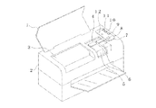
図1は、本発明のインクジェット記録装置の一実施例を示すものであって、開閉可能なケースカバー1と、ケース本体2とからなるケースに後述する印刷機構を収容して構成され、ケース本体2には印刷領域3から離れた位置にカートリッジ交換領域を区分する窓4が形成されている。
【0009】
窓4は、キャリッジに搭載された2つのインクカートリッジ5、6の何れか一方のみの上面が全て露出するサイズに形成され、またケースカーバ1が閉じられたとき、本体ケース2の露出する領域には、操作パネル7が設けらていて、ここに電源スイッチ8、カートリッジ交換指令スイッチ9、クリーニング指令スイッチ10、継続指令スイッチ11の他に、表示器12が配置されている。
【0010】
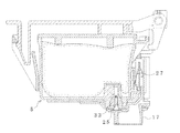
図2は、本発明のインクジェット記録装置の一実施例を、印刷機構部について示すものであって、タイミングベルト13を介して駆動モータ14に接続されたキャリッジ15には、上面に後述する黒インクを収容したブラックインクカートリッジ5と、カラーインクを収容したカラーインクカートリッジ6を格納するホルダ16が形成され、また下面には各インクカートリッジ5、6からインクの供給を受ける記録ヘッド17が設けられている。
【0011】
キャリッジ15は、フレキシブルケーブル18を介して後述する制御装置19に接続されていて、記録ヘッド17に印刷信号を供給したり、またインクカートリッジ5、6の記憶手段53との通信が可能に構成されている。
【0012】
非印字領域には、記録ヘッド17をクリーニングするクリーニングブレード20や、記録ヘッド17を封止してインクの乾燥を防止するとともに、ポンプユニット21からの負圧の供給を受けて目詰まりを解消するキャッピング手段22が設けられている。なお、図中符号23は、紙送りローラ24及びポンプユニット21を駆動する紙送りモータを示す。
【0013】
図3は、ブラックインクカートリッジ5とカラーインクカートリッジ6の一実施例を示すものであって、容器31、41にインクを収容して上面を蓋体32、42により封止されている。インクは、容器31、42に多孔質体を充填し、これに含浸させた状態で収容されている。
容器31、41の底面には、キャリッジ11のホルダ116に装着されたときインク供給針25、26と気密的に係合するインク供給口33、43が形成され、容器31、41の一側面には回路基板50が固定されている。
【0014】
回路基板50は、図4(a)、(b)に示したようにインクカートリッジ5、6に取付けられたとき表面となる側に、記録装置のカートリッジホルダ12に形成された接点27(図5)とのコンタクトを形成する電極51、52が形成され、また裏面には半導体記憶手段53がアクセス可能に実装されている。
【0015】
半導体記憶手段53は、電気的に書換え可能な不揮発性メモリにより構成され、当該カートリッジを特定するためのシリアル番号、カートリッジに収容されているインクの量、カートリッジ5、6の形式、製品の出所を明確にする商標に関するデータ等が工場出荷時に予め書き込まれている。
【0016】
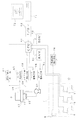
図6は、前述の制御装置15の一実施例を示すものであって、CPU60、RAM61、ROM62によりマイクロコンピュータが構成されていて、インターフェース63を介してホスト71に接続されている。RAM61は、CPU61のワークメモリとして機能し、読出/書込手段64によりインクカートリッジの半導体記憶手段53から読出したインクカートリッジ5のデータを一時的に格納する領域を備え、またROM62は、制御プログラムを格納している。
【0017】
インクカートリッジ検出手段65は、各インクカートリッジ5、6の回路基板50の大きめに形成された電極52を介して導通される2つの接点の導通状態、つまり装着された場合には導通路が形成され、また未装着の場合には開放されていることに基づいて装着の有無を検出する。
【0018】
このように構成された装置は、ホスト71からの印刷データに基づいてヘッド駆動手段66により記録ヘッド17に駆動信号を出力してインク滴を吐出させ、またクリーニング指令スイッチ10等によりインク滴吐出回復の操作が指令された場合には、ポンプ駆動手段67によりポンプユニット21を作動させて記録ヘッド17からインクを強制的に排出させる。これら印刷やクリーニングにより使用されたインク量は、マイクロコンピュータにより計数され、ROM62に格納される。
【0019】
メディア種判定手段68は、センサー69からの信号に基づいて印刷媒体の種類、つまり普通紙、フィルム、コーテング紙を判別してCPU60に出力するものである。このようなメデイアの判定は、記録媒体の反射率を検出したり、またメディアの裏面や隅等の非印刷領域に各メディアの種類を特定するデータをセンサーにより読取り可能な形態で予め印刷しておくことにより容易に判定することができる。
なお、図中符号70は、操作パネル7の電源スイッチ8が操作されてから装置の終了処理を完了するまでに電力を供給し、その後に商用電源の電力を断つ電源遮断手段を示す。
【0020】
次にこのように構成した装置の動作を図7に示したフローチャートに基づいて説明する。
記録装置は、周知のようにケーブルによりホスト71に接続されていて、ホスト71に予めインストールされている当該記録装置を駆動するためのドライバソフトウエアにより制御を受ける。
この状態でインクカートリッジを交換すべく、ドライバソフトウエアを起動してインクカートリッジ交換メニューを表示させ、インクカートリッジ交換を指令したり、またカートリッジ交換指令スイッチ9を操作する。
【0021】
これにより、ホスト71から記録装置に交換指令信号が出力し、記録装置のマイクロコンピュータにより所定の処理、つまりキャリッジ15をインクカートリッジ交換位置に移動させ、インクカートリッジが交換された段階で(ステップ イ)、読出/書込手段64を介してインクカートリッジ5の半導体記憶手段53から、データを読出して当該記録装置に適合するデータであるか、否かを判定する(ステップ ロ)。適合する場合にはキャリッジ15を充填位置に移動させて(ステップ ハ)記録ヘッド17をキャッピングユニット22により封止させてからポンプユニット21を作動させて記録ヘッド17にインクを充填させる(ステップ ニ)。
【0022】
この動作により、インクカートリッジの交換による着脱時に必然的に記録ヘッドに侵入する気泡を確実に排出して以後の印字品質を確保することができ、またインク種が異なるインクカートリッジに交換された場合には異種のインクを記録ヘッドから確実に排出して印字不良を防止することができる。
【0023】
一方、適合することが確認できない場合には、マイクロコンピュータは、パネル7の表示器12にインクカートリッジの確認を促す警告の表示を行い、またホスト71に信号を出力してホスト71のデイスプレイ72にインクカートリッジの確認を促す表示、及び適合するインクカートリッジの包装デザイン等の表示をデイスプレイ72に行い(ステップ ホ)、インクカートリッジの交換が可能な位置にキャリッジ15を移動させる(ステップ ヘ)。
【0024】
なお、表示するデータとしてはインクカートリッジのモデル名、または型名であってもよく、さらには印刷用途毎に適合するインクカートリッジの包装デザイン、モデル名、型名を表示すると、ユーザに的確な情報を提供することができる。また、必要に応じてはこれらインクカートリッジの取扱店の連絡先を表示することもできる。これにより、不慣れなユーザにあっても購入の際にこの表示を参考にして誤ったインクカートリッジを購入することなく、適合品を確実に購入することができる。
このように、インクカートリッジが装着され、記録ヘッド17へのインクの充填が行われる以前に警報を発することにより、種類が異なるインクが記録ヘッド17に流入して記録ヘッド17を破損したり、また印刷品質が劣化するのを未然に防止することができる。
継続指令スイッチ11が操作されることなく、インクカートリッジが交換されると(ステップ チ)、前述のステップ(ロ)にジャンプして前述の判定を行う。
【0025】
一方、このような警告にも関わらず、パネル7の継続指令スイッチ11が押圧されると(ステップ ト)、キャリッジ15を充填位置に移動させて(ステップハ)記録ヘッド17をキャッピングユニット22により封止してから適合するインクカートリッジが装着された場合と同様にインク充填動作を実行する(ステップ ニ)。
【0026】
なお、ステップ(ホ)の警告後にインクカートリッジの交換も行われること無く、所定時間が経過すると(ステップ リ)、当該記録装置、さらには現在の記録媒体に適合するインクカートリッジの包装に施されているデザイン等、適合するインクカートリッジを特定するのに有用な情報をホスト71のデスプレイ72に表示する(ステップ ヌ)。これにより、不慣れなユーザにあっても購入の際にこの表示を参考にして、インクカートリッジを誤購入することなく、適合品を確実に購入することができる。
【0027】
このようにして印刷可能な状態になり(ステップ ル)、ホストから印字指令が入力すると(ステップ オ)、マイクコンピュータはヘッド駆動手段66により記録ヘッド17を駆動してインク滴を吐出させて印刷動作を実行する(ステップ ワ)。
印刷により消費されるインクは、ヘッド駆動手段66から出力される駆動信号をカウントすることにより管理される。
また印刷中等にインク滴の吐出能力が低下した場合には、キャリッジ15を移動させて記録ヘッドをキャッピングユニット22により封止し、ポンプユニット21を作動させて記録ヘッド17からインクを強制的に排出させてノズル開口の目詰まりを解消させ、同時にこの時に排出されたインク量をポンプユニット21の駆動時間等として管理する。
【0028】
当該インクカートリッジが装着されてからのインク消費量が、ニアエンド、つまり記録ヘッド17のインクが空になる直前のインク量まで減少すると(ステップ カ)、ホスト71に信号を出力してホスト71のデイスプレイ72にインクエンドを表示させ、ユーザにインクカートリッジの交換を促す。なお、ニアエンド警報を見過ごしてインクが消費され尽くた場合には、印刷を強制的に停止して、インクカートリッジの交換を要求する表示を行う。
【0029】
同時に、当該記録装置に適合するインクカートリッジの包装に施されているデザイン等、適合するインクカートリッジを特定するのに有用な情報をホスト71のディスプレイ72に表示する(ステップ ヌ)。これにより、不慣れなユーザにあっても購入の際にこの表示を参考にして誤ったインクカートリッジを購入することなく、適合品を確実に購入することができる。
【0030】
そして、電源スイッチ8により電源のオフが指令されると(ステップ ヨ)、RAM61のインクカートリッジに関するデータをROM62に退避させる他、終了処理が完了した段階で電源が断たれる(ステップ タ)。
【0031】
なお、上述の実施例においては、インクカートリッジがニアエンド、またはインクエンドとなった段階で(ステップ カ)、適合品のデザインや型名を表示するようにしているが(ステップ ヌ)、図8に示したようにインクニアエンド、またはインクエンドとなった段階で(図8 ステップカ)、現在装着されているインクカートリッジの適合性を判定し(図8 ステップ レ)、適合品の場合は前述の実施例と同様に現在装着されている適合インクカートリッジのデザインを表示し、また非適合品の場合には当該記録装置に適合する複数のインクカートリッジの型名やモデル名を一覧表示して(ステップ ツ)電源スイッチ8の操作を待つ(ステップ ヨ)。
【0032】
このように、適合品が装着されている場合には、引き続き同一の印刷品質を確保するできるインクカートリッジの選択を容易化し、また非適合品の場合には当該記録装置に適合する複数のインクカートリッジの型名やモデル名を一覧表示することにより、ユーザに当該記録装置に適合するあらゆるインクカートリッジを提示して、ユーザのニーズに適したインクカートリッジの選択を支援することができる。
【0033】
とろこで、インクジェット記録装置による印刷物は、記録媒体表面でのインク滴の滲みや浸透の具合により印字品質が大きく左右されるため、印刷目的や用途に応じて記録媒体が選択され、さらには記録媒体に最適なインクが用意されている。このため、取扱になれないユーザにあっては、記録媒体とインクカートリッジとが適合しているか否かの判断が困難である。
【0034】
図9は、記録媒体とインクカートリッジとの適合性をも判定してユーザに最適なインクカートリッジ及び記録媒体の購入を支援する一実施例を示すフローチャートである。
インクカートリッジが交換された段階で(ステップ イ)、読出/書込手段64を介してインクカートリッジの半導体記憶手段53から、データを読出して当該記録装置に適合するデータであるか、否かを判定する(ステップ ロ)。当該インクカートリッジが記録装置に適合するものである場合には、メディア判定手段68により記録媒体の種類を判定する(ステップ ハ)。装着されているインクカートリッジが記録媒体に適合する場合には(ステップ ニ)、キャリッジ15を移動させて記録ヘッド17をキャッピングユニット22により封止させて(ステップ ホ)、ポンプユニット21により記録ヘッド17にインクを充填させる(ステップ ヘ)。
【0035】
一方、インクカートリッジが記録装置や記録媒体との適合性が確認できない場合には、マイクロコンピュータは、インクカートリッジの確認を促す警告の表示を行い、適合する記録用紙とインクカートリッジとの組み合わせを一覧表示し(ステップ ト)、インクカートリッジの交換が可能な位置にキャリッジ15を移動させる(ステップ チ)。なお、表示するデータとしては一覧表示ばかりでなく、インクカートリッジ及び記録用紙の包装デザインであってもよい。そして、これらインクカートリッジと記録媒体との最適な組み合わせのデータは、インクカートリッジの記憶手段53もしくはROM62に格納されている。
【0036】
継続指令スイッチ11が操作されることなく、インクカートリッジが交換されると(ステップ ヌ)、前述のステップ(ロ)にジャンプして前述の判定動作を実行する。
【0037】
一方、このような警告にも関わらず、パネル7の継続指令スイッチ11が押圧されると(ステップ リ)、キャリッジ15を充填位置に移動させて(ステップホ)適合するインクカートリッジが装着された場合と同様にインク充填動作を実行する(ステップ ヘ)。
【0038】
なお、ステップ(ト)の警告後にインクカートリッジの交換も行われること無く、所定時間が経過すると(ステップ ル)、前述のステップ(ト)と同様の表示を実行して(ステップ オ)、記録媒体とインクカートリッジとの不適合な組み合わせとなる誤購入を防止するための支援を行う。
【0039】
このようにして印刷可能な状態になり(ステップ ワ)、印字指令が入力すると(ステップ カ)、印刷動作を実行する(ステップ ヨ)。
【0040】
当該インクカートリッジ5が装着されてからのインク消費量が、ニアエンド、もしくはインクエンドとなると(ステップ タ)、ホスト71に信号を出力してユーザにインクカートリッジの交換を促し、同時に当該記録装置に適合するインクカートリッジの包装に施されているデザイン等、適合するインクカートリッジを特定するのに有用な情報を表示する(ステップ レ)。これにより、ユーザは、記録媒体に適合したインクカートリッジを確実に購入することができる。
【0041】
そして、電源スイッチ8により電源のオフが指令されると(ステップ ソ)、RAM61のインクカートリッジに関するデータをROM62に退避させる他、終了処理が完了した段階で電源が断たれる(ステップ ツ)。
【0042】
この実施例によれば、記録装置との適合性だけでなく、記録装置により印刷を行う記録媒体に適合したインクカートリッジを誤り無く購入することができる。
【0043】
なお、上述の実施例においては、センサー69からの信号に基づいてメディア判定手段68により記録媒体の種類を検出しているが、記録装置に設けたスイッチや、ホストからメディアの種類を選択、指定するようにしても同様の作用を奏することは明らかである。
【0044】
また上述の実施例においては、適合するインクカートリッジやメディアの情報を、ホストに接続されたディスプレイや記録装置のディスプレイに表示しているが、必要に応じてインクエンドの直前にこれらの情報を印刷してハードコピーを出力するようにすることもできる。
【図面の簡単な説明】
【図1】本発明のインクジェット記録装置の一実施例を示す図である。
【図2】同上装置の印刷機構について示す図である。
【図3】図(a)、(b)は、それぞれ同上装置に使用するブラックインク用、及びカラーインク用インクカートリッジの一実施例を示す図である。
【図4】図(a)、(b)は、それぞれ同上インクカートリッジに装着されている回路基板の表裏の構造を示す図である。
【図5】同上記録装置にブラックインクカートリッジを装着した状態で示す断面図である。
【図6】本発明の一実施例を示すブロック図である。
【図7】同上装置の動作を示すフローチャートである。
【図8】本発明の他の実施例を示すフローチャートである。
【図9】同上装置によりメディアとの関連でインクカートリッジの適合性を判定する一実施例を示すフローチャートである。
【符号の説明】
5、6 インクカートリッジ
7 操作パネル
17 記録ヘッド
50 回路基板
53 半導体記憶手段[0001]
[Technical field to which the invention belongs]
The present invention relates to a recording apparatus that performs printing on a recording medium while receiving ink supplied from a replaceable ink cartridge and discharging ink droplets from nozzle openings.
[0002]
[Prior art]
The ink jet recording apparatus supplies a drive signal corresponding to print data to a piezoelectric vibrator, a heat generating means, etc., pressurizes the ink with energy generated by the piezoelectric vibrator, the heat generating means, etc., and discharges ink droplets from the nozzle openings. A recording head and an ink cartridge containing ink for supplying ink to the recording head are provided.
Since the print quality is determined not only by the resolution of the recording head but also greatly depends on the quality of the ink, as shown in JP-A-7-227971, the ink amount of the ink cartridge is determined, and the ink quality is determined. There has been proposed an ink jet recording apparatus that supports the purchase of an ink cartridge suitable for the recording apparatus by printing the type name of the ink cartridge on a recording sheet when the cartridge needs to be replaced.
[0003]
[Problems to be solved by the invention]
According to this, although it is possible to eliminate the need for a user to check the model name, etc., if an incompatible ink cartridge is still installed by mistake, ink that is not compatible with the recording apparatus is applied to the recording head. Since the ink is filled, not only the printing quality is extremely lowered but also the recording head may be damaged.
[0004]
On the other hand, ink has been improved with the aim of further improving print quality, and a plurality of types of ink cartridges are being prepared for the same apparatus. In other words, the ink jet recording apparatus can print with high quality not only on plain paper but also on display film and coating paper by exchanging ink. For users who do not, there is a problem that it makes it difficult to purchase the target product properly.
[0005]
The present invention has been made in view of such circumstances, and an object of the present invention is to make it possible to fill the recording head with non-conforming ink when a non-conforming ink cartridge is mounted. It is an object of the present invention to provide an ink jet recording apparatus capable of supporting the selection of an appropriate ink cartridge and urging the user to install a suitable ink cartridge while preventing the above.
Another object of the present invention is that when an incompatible ink cartridge is mounted on a recording medium, before the recording head is filled with the incompatible ink, a variety of ink cartridges are selected. It is an object to provide an ink jet recording apparatus that can perform printing in an optimum state by providing an ink cartridge suitable for a user's printing form and support for accurately selecting a medium.
[0006]
[Means for Solving the Problems]
In order to solve such a problem, in the present invention, an ink jet recording head and an ink cartridge for supplying ink to the ink jet recording head attached with storage means storing at least data for specifying the ink cartridge, Control means for controlling the recording head in response to print data, and media determining means for determining the type of recording medium loaded in the recording apparatus, the control means comprising the ink cartridge, the recording head, When the compatibility with the recording medium cannot be confirmed, the packaging design data of the packaging material which is a guideline for the user to discriminate the recording head and the ink cartridge compatible with the recording medium is output.
[0007]
[Action]
If an ink cartridge whose compatibility with the recording device cannot be confirmed is installed, or a recording medium that does not match the ink in the ink cartridge is loaded, the packaging design of the compatible product is displayed before filling the recording head with ink. It is possible to support the purchase of an ink cartridge or a recording medium that is most suitable for an unfamiliar user.
[0008]
DETAILED DESCRIPTION OF THE INVENTION
Therefore, details of the present invention will be described below based on the illustrated embodiments.
FIG. 1 shows an embodiment of an ink jet recording apparatus according to the present invention, which is configured by accommodating a printing mechanism (to be described later) in a case comprising an openable /
[0009]
The
[0010]
FIG. 2 shows an embodiment of an ink jet recording apparatus according to the present invention with respect to a printing mechanism. A
[0011]
The
[0012]
In the non-printing area, the
[0013]
FIG. 3 shows an embodiment of the
In the bottom surfaces of the
[0014]
As shown in FIGS. 4A and 4B, the
[0015]
The semiconductor storage means 53 is composed of an electrically rewritable non-volatile memory. The serial number for specifying the cartridge, the amount of ink contained in the cartridge, the types of
[0016]
FIG. 6 shows an embodiment of the
[0017]
The ink cartridge detection means 65 has a conduction state of two contact points that are conducted through the
[0018]
The apparatus configured in this way outputs a drive signal to the
[0019]
The media
[0020]
Next, the operation of the apparatus configured as described above will be described based on the flowchart shown in FIG.
As is well known, the recording apparatus is connected to the host 71 via a cable, and is controlled by driver software for driving the recording apparatus installed in the host 71 in advance.
In order to replace the ink cartridge in this state, the driver software is started to display the ink cartridge replacement menu, and the ink cartridge replacement command is commanded or the cartridge replacement command switch 9 is operated.
[0021]
As a result, an exchange command signal is output from the host 71 to the recording apparatus, and the microcomputer of the recording apparatus performs predetermined processing, that is, the
[0022]
This operation ensures that the air bubbles that inevitably enter the recording head when the ink cartridge is replaced and removed are secured to ensure the subsequent print quality, and when the ink cartridge is replaced with a different ink cartridge. Can reliably discharge different kinds of ink from the recording head to prevent printing defects.
[0023]
On the other hand, if it cannot be confirmed, the microcomputer displays a warning for confirming the ink cartridge on the display 12 of the
[0024]
The data to be displayed may be the model name or model name of the ink cartridge. Furthermore, when the packaging design, model name, and model name of the ink cartridge suitable for each printing application are displayed, accurate information is displayed to the user. Can be provided. Further, if necessary, the contact information of the dealer of these ink cartridges can be displayed. Thereby, even an unfamiliar user can reliably purchase a compatible product without purchasing an incorrect ink cartridge with reference to this display at the time of purchase.
In this way, by issuing an alarm before the ink cartridge is mounted and the
If the ink cartridge is replaced without operating the continuation command switch 11 (step h), the process jumps to step (b) described above to make the above determination.
[0025]
On the other hand, when the continuation command switch 11 on the
[0026]
After the warning of step (e), the ink cartridge is not replaced, and when a predetermined time has passed (step), the ink cartridge is applied to the recording device and the ink cartridge package suitable for the current recording medium. Information useful for identifying a suitable ink cartridge, such as a design that is present, is displayed on the
[0027]
When printing is possible in this way (step 1) and a print command is input from the host (step 0), the microphone computer drives the
The ink consumed by printing is managed by counting the drive signal output from the head drive unit 66.
Also, when the ink droplet ejection capacity is reduced during printing or the like, the
[0028]
When the ink consumption after the ink cartridge is mounted decreases to the near-end, that is, the ink amount just before the
[0029]
At the same time, information useful for identifying a compatible ink cartridge, such as a design applied to the packaging of the ink cartridge compatible with the recording apparatus, is displayed on the
[0030]
When the power switch 8 is instructed to turn off the power (step YO), the data relating to the ink cartridge in the
[0031]
In the above-described embodiment, when the ink cartridge is near-end or ink-end (step KA), the design and model name of the compatible product are displayed (step NU). As shown, when ink near end or ink end is reached (step 8 in FIG. 8), the compatibility of the currently installed ink cartridge is determined (step 8 in FIG. 8). As in the example, the design of the compatible ink cartridge that is currently installed is displayed, and if it is a non-conforming product, the model names and model names of multiple ink cartridges that are compatible with the recording device are displayed in a list (Steps ) Wait for the operation of the power switch 8 (step Y).
[0032]
As described above, when a compatible product is mounted, it is possible to easily select an ink cartridge that can ensure the same print quality, and, in the case of a non-compliant product, a plurality of ink cartridges that are compatible with the recording apparatus. By displaying a list of model names and model names, it is possible to present to the user all ink cartridges suitable for the recording apparatus, and to assist in selecting an ink cartridge suitable for the user's needs.
[0033]
Since the print quality of the printed matter by the ink jet recording apparatus greatly depends on the ink droplet bleeding or penetration on the surface of the recording medium, the recording medium is selected according to the printing purpose and application, and further the recording is performed. Ink suitable for the medium is prepared. For this reason, it is difficult for a user who cannot be handled to determine whether the recording medium and the ink cartridge are compatible.
[0034]
FIG. 9 is a flowchart showing an embodiment for determining the compatibility between the recording medium and the ink cartridge and assisting the user in purchasing the optimum ink cartridge and recording medium.
When the ink cartridge is replaced (Step A), the data is read from the semiconductor storage means 53 of the ink cartridge via the read / write means 64 to determine whether the data is suitable for the recording apparatus. (Step B). If the ink cartridge is compatible with the recording apparatus, the
[0035]
On the other hand, when the compatibility of the ink cartridge with the recording device or recording medium cannot be confirmed, the microcomputer displays a warning prompting confirmation of the ink cartridge and displays a list of combinations of compatible recording paper and ink cartridge. Then, the
[0036]
If the ink cartridge is replaced without operating the continuation command switch 11 (step No), the process jumps to the above-described step (b) and executes the above-described determination operation.
[0037]
On the other hand, when the continuation command switch 11 on the
[0038]
After the warning in step (g), the ink cartridge is not replaced, and when a predetermined time has passed (step), the same display as in step (g) described above is executed (step e), and the recording medium Assistance to prevent mis-purchase that would result in an incompatible combination of ink cartridge and ink cartridge.
[0039]
In this way, the printer is ready for printing (step W), and when a print command is input (step K), the printing operation is executed (step Y).
[0040]
When the ink consumption after the
[0041]
When the power switch 8 is instructed to turn off the power (step S), the data relating to the ink cartridge in the
[0042]
According to this embodiment, not only the compatibility with the recording apparatus but also the ink cartridge suitable for the recording medium to be printed by the recording apparatus can be purchased without error.
[0043]
In the above-described embodiment, the type of the recording medium is detected by the
[0044]
In the above-described embodiment, information on compatible ink cartridges and media is displayed on the display connected to the host or the display of the recording device. However, if necessary, the information is printed immediately before the ink end. You can also output a hard copy.
[Brief description of the drawings]
FIG. 1 is a diagram showing an embodiment of an ink jet recording apparatus of the present invention.
FIG. 2 is a diagram showing a printing mechanism of the apparatus.
FIGS. 3A and 3B are diagrams showing an embodiment of an ink cartridge for black ink and color ink respectively used in the apparatus.
FIGS. 4A and 4B are diagrams showing the front and back structures of a circuit board mounted on the same ink cartridge. FIG.
FIG. 5 is a cross-sectional view showing a state where a black ink cartridge is mounted on the recording apparatus.
FIG. 6 is a block diagram showing an embodiment of the present invention.
FIG. 7 is a flowchart showing the operation of the apparatus.
FIG. 8 is a flowchart showing another embodiment of the present invention.
FIG. 9 is a flowchart showing an embodiment for determining compatibility of an ink cartridge in relation to a medium by the apparatus.
[Explanation of symbols]
5, 6
Claims (1)
前記制御手段が、前記インクカートリッジと前記記録ヘッド、及び記録媒体との適合性を確認できない場合には、前記記録ヘッド、及び記録媒体に適合するインクカートリッジをユーザが判別するための目安となる包材の包装デザインのデータを出力するインクジェット記録装置。An ink jet recording head, an ink cartridge for supplying ink to the ink jet recording head attached with storage means for storing at least data for specifying the ink cartridge, and a control means for controlling the recording head in response to print data And media determination means for determining the type of recording medium loaded in the recording apparatus,
When the control unit cannot confirm the compatibility between the ink cartridge, the recording head, and the recording medium, a package that is a guideline for the user to determine the ink cartridge that is compatible with the recording head and the recording medium. Inkjet recording device that outputs packaging design data.
Priority Applications (6)
| Application Number | Priority Date | Filing Date | Title |
|---|---|---|---|
| JP25675299A JP3748018B2 (en) | 1999-09-10 | 1999-09-10 | Inkjet recording device |
| EP00902971A EP1080917B1 (en) | 1999-02-15 | 2000-02-15 | Ink jet recorder |
| PCT/JP2000/000821 WO2000047417A1 (en) | 1999-02-15 | 2000-02-15 | Ink jet recorder |
| DE60032842T DE60032842T2 (en) | 1999-02-15 | 2000-02-15 | INKJET |
| US09/688,187 US6971732B1 (en) | 1999-02-15 | 2000-10-16 | Ink jet recording apparatus |
| HK01105697A HK1034932A1 (en) | 1999-02-15 | 2001-08-14 | Ink jet recorder |
Applications Claiming Priority (1)
| Application Number | Priority Date | Filing Date | Title |
|---|---|---|---|
| JP25675299A JP3748018B2 (en) | 1999-09-10 | 1999-09-10 | Inkjet recording device |
Publications (2)
| Publication Number | Publication Date |
|---|---|
| JP2001080089A JP2001080089A (en) | 2001-03-27 |
| JP3748018B2 true JP3748018B2 (en) | 2006-02-22 |
Family
ID=17296963
Family Applications (1)
| Application Number | Title | Priority Date | Filing Date |
|---|---|---|---|
| JP25675299A Expired - Fee Related JP3748018B2 (en) | 1999-02-15 | 1999-09-10 | Inkjet recording device |
Country Status (1)
| Country | Link |
|---|---|
| JP (1) | JP3748018B2 (en) |
Families Citing this family (3)
| Publication number | Priority date | Publication date | Assignee | Title |
|---|---|---|---|---|
| US6789864B2 (en) | 2002-08-13 | 2004-09-14 | Hewlett-Packard Development Company, L.P. | Systems and methods for refilling printing cartridges |
| JP2006082567A (en) * | 2005-12-16 | 2006-03-30 | Seiko Epson Corp | Ink cartridge |
| JP6955892B2 (en) * | 2017-04-25 | 2021-10-27 | 理想科学工業株式会社 | Consumables ordering system and printing equipment |
-
1999
- 1999-09-10 JP JP25675299A patent/JP3748018B2/en not_active Expired - Fee Related
Also Published As
| Publication number | Publication date |
|---|---|
| JP2001080089A (en) | 2001-03-27 |
Similar Documents
| Publication | Publication Date | Title |
|---|---|---|
| JP3726286B2 (en) | Inkjet recording apparatus and ink cartridge | |
| US6971732B1 (en) | Ink jet recording apparatus | |
| JP3455798B2 (en) | Ink jet recording apparatus, ink cartridge and ink replenishing tool used therefor | |
| EP1080911B1 (en) | Print system, ink jet printer and method for managing an effectively usable period of an ink cartridge | |
| EP1403068B1 (en) | Ink jet recording apparatus | |
| JP2000198220A (en) | Ink-jet recording apparatus, and ink cartridge | |
| JP2001130026A (en) | Ink jet printer, method of accessing memory device on ink cartridge and method of controlling the printer | |
| JP2000103087A (en) | Ink jet recorder and ink cartridge | |
| JP3512060B2 (en) | Ink jet recording device | |
| JPH04316856A (en) | Detector for ink residual quantity of ink jet printer | |
| EP2133205B1 (en) | Fluid discharge device, control method for a fluid discharge device, and fluid tank | |
| JP3748018B2 (en) | Inkjet recording device | |
| JP3478332B2 (en) | Ink jet recording device | |
| JP3664222B2 (en) | Inkjet recording device | |
| JPH091819A (en) | Ink jet recording apparatus | |
| JP3201454B2 (en) | Ink jet recording device | |
| JP3664223B2 (en) | Inkjet recording device | |
| JP3685240B2 (en) | Inkjet recording device | |
| JPH05169675A (en) | Ink jet recording apparatus and recovering method therefor | |
| JP2001138547A (en) | Ink jet recorder, ink jet recording method, ink cartridge, and method for managing available period of ink cartridge | |
| JP2007118339A (en) | Inkjet printer, method for restoring function of inkjet printer, and program | |
| JP3823445B2 (en) | Ink jet recording apparatus and ink cartridge replacement method | |
| JP2005199497A (en) | Ink cartridge and apparatus for detecting remaining amount of ink | |
| JP4266263B2 (en) | Inkjet recording apparatus and image forming apparatus | |
| JP2004160938A (en) | Liquid jet device and liquid vessel used therefor |
Legal Events
| Date | Code | Title | Description |
|---|---|---|---|
| A131 | Notification of reasons for refusal |
Free format text: JAPANESE INTERMEDIATE CODE: A131 Effective date: 20040609 |
|
| A131 | Notification of reasons for refusal |
Free format text: JAPANESE INTERMEDIATE CODE: A131 Effective date: 20050316 |
|
| A521 | Written amendment |
Free format text: JAPANESE INTERMEDIATE CODE: A523 Effective date: 20050516 |
|
| TRDD | Decision of grant or rejection written | ||
| A01 | Written decision to grant a patent or to grant a registration (utility model) |
Effective date: 20051109 Free format text: JAPANESE INTERMEDIATE CODE: A01 |
|
| A61 | First payment of annual fees (during grant procedure) |
Effective date: 20051122 Free format text: JAPANESE INTERMEDIATE CODE: A61 |
|
| R150 | Certificate of patent (=grant) or registration of utility model |
Free format text: JAPANESE INTERMEDIATE CODE: R150 |
|
| FPAY | Renewal fee payment (prs date is renewal date of database) |
Year of fee payment: 4 Free format text: PAYMENT UNTIL: 20091209 |
|
| FPAY | Renewal fee payment (prs date is renewal date of database) |
Year of fee payment: 5 Free format text: PAYMENT UNTIL: 20101209 |
|
| FPAY | Renewal fee payment (prs date is renewal date of database) |
Free format text: PAYMENT UNTIL: 20101209 Year of fee payment: 5 |
|
| FPAY | Renewal fee payment (prs date is renewal date of database) |
Year of fee payment: 6 Free format text: PAYMENT UNTIL: 20111209 |
|
| LAPS | Cancellation because of no payment of annual fees |