JP3734508B2 - Device for detecting electromagnetic reflected waves from biological tissue - Google Patents
Device for detecting electromagnetic reflected waves from biological tissue Download PDFInfo
- Publication number
- JP3734508B2 JP3734508B2 JP50070797A JP50070797A JP3734508B2 JP 3734508 B2 JP3734508 B2 JP 3734508B2 JP 50070797 A JP50070797 A JP 50070797A JP 50070797 A JP50070797 A JP 50070797A JP 3734508 B2 JP3734508 B2 JP 3734508B2
- Authority
- JP
- Japan
- Prior art keywords
- imaging apparatus
- light source
- light
- image
- image detector
- Prior art date
- Legal status (The legal status is an assumption and is not a legal conclusion. Google has not performed a legal analysis and makes no representation as to the accuracy of the status listed.)
- Expired - Fee Related
Links
Images


Classifications
-
- A—HUMAN NECESSITIES
- A61—MEDICAL OR VETERINARY SCIENCE; HYGIENE
- A61B—DIAGNOSIS; SURGERY; IDENTIFICATION
- A61B5/00—Measuring for diagnostic purposes; Identification of persons
- A61B5/48—Other medical applications
- A61B5/4887—Locating particular structures in or on the body
- A61B5/489—Blood vessels
-
- A—HUMAN NECESSITIES
- A61—MEDICAL OR VETERINARY SCIENCE; HYGIENE
- A61B—DIAGNOSIS; SURGERY; IDENTIFICATION
- A61B5/00—Measuring for diagnostic purposes; Identification of persons
- A61B5/0059—Measuring for diagnostic purposes; Identification of persons using light, e.g. diagnosis by transillumination, diascopy, fluorescence
-
- A—HUMAN NECESSITIES
- A61—MEDICAL OR VETERINARY SCIENCE; HYGIENE
- A61B—DIAGNOSIS; SURGERY; IDENTIFICATION
- A61B5/00—Measuring for diagnostic purposes; Identification of persons
- A61B5/15—Devices for taking samples of blood
- A61B5/150007—Details
- A61B5/150015—Source of blood
- A61B5/15003—Source of blood for venous or arterial blood
-
- A—HUMAN NECESSITIES
- A61—MEDICAL OR VETERINARY SCIENCE; HYGIENE
- A61B—DIAGNOSIS; SURGERY; IDENTIFICATION
- A61B5/00—Measuring for diagnostic purposes; Identification of persons
- A61B5/15—Devices for taking samples of blood
- A61B5/150007—Details
- A61B5/150748—Having means for aiding positioning of the piercing device at a location where the body is to be pierced
-
- A—HUMAN NECESSITIES
- A61—MEDICAL OR VETERINARY SCIENCE; HYGIENE
- A61B—DIAGNOSIS; SURGERY; IDENTIFICATION
- A61B90/00—Instruments, implements or accessories specially adapted for surgery or diagnosis and not covered by any of the groups A61B1/00 - A61B50/00, e.g. for luxation treatment or for protecting wound edges
- A61B90/36—Image-producing devices or illumination devices not otherwise provided for
-
- A—HUMAN NECESSITIES
- A61—MEDICAL OR VETERINARY SCIENCE; HYGIENE
- A61B—DIAGNOSIS; SURGERY; IDENTIFICATION
- A61B17/00—Surgical instruments, devices or methods, e.g. tourniquets
- A61B17/34—Trocars; Puncturing needles
- A61B17/3403—Needle locating or guiding means
-
- A—HUMAN NECESSITIES
- A61—MEDICAL OR VETERINARY SCIENCE; HYGIENE
- A61B—DIAGNOSIS; SURGERY; IDENTIFICATION
- A61B90/00—Instruments, implements or accessories specially adapted for surgery or diagnosis and not covered by any of the groups A61B1/00 - A61B50/00, e.g. for luxation treatment or for protecting wound edges
- A61B90/30—Devices for illuminating a surgical field, the devices having an interrelation with other surgical devices or with a surgical procedure
- A61B2090/306—Devices for illuminating a surgical field, the devices having an interrelation with other surgical devices or with a surgical procedure using optical fibres
-
- A—HUMAN NECESSITIES
- A61—MEDICAL OR VETERINARY SCIENCE; HYGIENE
- A61B—DIAGNOSIS; SURGERY; IDENTIFICATION
- A61B90/00—Instruments, implements or accessories specially adapted for surgery or diagnosis and not covered by any of the groups A61B1/00 - A61B50/00, e.g. for luxation treatment or for protecting wound edges
- A61B90/36—Image-producing devices or illumination devices not otherwise provided for
- A61B90/37—Surgical systems with images on a monitor during operation
- A61B2090/373—Surgical systems with images on a monitor during operation using light, e.g. by using optical scanners
-
- A—HUMAN NECESSITIES
- A61—MEDICAL OR VETERINARY SCIENCE; HYGIENE
- A61B—DIAGNOSIS; SURGERY; IDENTIFICATION
- A61B90/00—Instruments, implements or accessories specially adapted for surgery or diagnosis and not covered by any of the groups A61B1/00 - A61B50/00, e.g. for luxation treatment or for protecting wound edges
- A61B90/50—Supports for surgical instruments, e.g. articulated arms
- A61B2090/502—Headgear, e.g. helmet, spectacles
-
- A—HUMAN NECESSITIES
- A61—MEDICAL OR VETERINARY SCIENCE; HYGIENE
- A61M—DEVICES FOR INTRODUCING MEDIA INTO, OR ONTO, THE BODY; DEVICES FOR TRANSDUCING BODY MEDIA OR FOR TAKING MEDIA FROM THE BODY; DEVICES FOR PRODUCING OR ENDING SLEEP OR STUPOR
- A61M5/00—Devices for bringing media into the body in a subcutaneous, intra-vascular or intramuscular way; Accessories therefor, e.g. filling or cleaning devices, arm-rests
- A61M5/42—Devices for bringing media into the body in a subcutaneous, intra-vascular or intramuscular way; Accessories therefor, e.g. filling or cleaning devices, arm-rests having means for desensitising skin, for protruding skin to facilitate piercing, or for locating point where body is to be pierced
- A61M5/427—Locating point where body is to be pierced, e.g. vein location means using ultrasonic waves, injection site templates
Landscapes
- Health & Medical Sciences (AREA)
- Life Sciences & Earth Sciences (AREA)
- Surgery (AREA)
- Animal Behavior & Ethology (AREA)
- Public Health (AREA)
- Pathology (AREA)
- Engineering & Computer Science (AREA)
- Biomedical Technology (AREA)
- Heart & Thoracic Surgery (AREA)
- Medical Informatics (AREA)
- Molecular Biology (AREA)
- Veterinary Medicine (AREA)
- General Health & Medical Sciences (AREA)
- Biophysics (AREA)
- Physics & Mathematics (AREA)
- Vascular Medicine (AREA)
- Hematology (AREA)
- Nuclear Medicine, Radiotherapy & Molecular Imaging (AREA)
- Oral & Maxillofacial Surgery (AREA)
- Investigating Or Analysing Materials By Optical Means (AREA)
- Measuring And Recording Apparatus For Diagnosis (AREA)
- Measuring Pulse, Heart Rate, Blood Pressure Or Blood Flow (AREA)
- Endoscopes (AREA)
- Measurement And Recording Of Electrical Phenomena And Electrical Characteristics Of The Living Body (AREA)
- Measurement Of The Respiration, Hearing Ability, Form, And Blood Characteristics Of Living Organisms (AREA)
- Magnetic Resonance Imaging Apparatus (AREA)
Abstract
Description
発明の背景
本発明は請求項1の前置き部分にかかる撮像装置に関する。詳述すれば、本発明は、例えば血液とかの目的構造体の特有の吸収特性と散乱特性とに感応する装置を利用して、人体における血管とかの解剖学的構造体の位置を同定するシステムに関する。更に、本発明は、血管とかの目的構造体とその周辺組織とのコントラストを高めるシステムと方法とにも関している。
米国では毎日、血管穿刺を伴う医学処置が数十万回も行われている。静脈穿刺として知られている処置は、応急液体や血液成分剤、手術時の麻酔液などの注入や、生物学的検査のための血液採集のために必要なものである。静脈に製剤を注入する場合での静脈穿刺法では注入量が限られている(a rate-limiting step)場合が多いが、通常の患者では半時間ほど、また、患者が新生児、幼児、老人、肥満患者、火傷患者の場合ではそれ以上の時間がかかる。患者に静脈穿刺の順が回ってくるまで診療室や健康管理プロバイダが待機していなければならないことから、総じて社会に対して莫大な財政負担がかかっているが、直ちに静脈穿刺が行えないのなら患者の生命が脅かされることがある。また、臨床医が血管の位置同定ができないと複数ヶ所穿刺することがあるが、その場合では疾病率が高くなることがある。
静脈穿刺が時として実施し難い理由は、血管は組織の比較的深いところにある場合が多く、通常の条件下では光学的吸収特性と光学的散乱特性の影響があって、血管を視認するのが不可能になっているからである。更に、血管はそれをいじると痙縮したり、狭窄したりすることから、事情が余計に悪い。それ故、健康管理プロバイダは、患者に対するリスクを減少し、時間を節約すると共に、処置にかかるコストの低減を計るために、リアルタイムにて血管を視認できていなければならない。また、処置に伴う時間を減少させることは、プロバイダが潜在的に汚染された穿刺針と接触するのを制限することができる。最後に、血管組織を視認できれば、血栓症やガン、血管不全などについての診断上及び治療上の重要な情報を得ることができる。
1970年の半ばに、外科手術医が表面上の血管を視認できるようにした器具が工夫されたとのことである。その器具は可視光源で構成されていて、皮膚にその光源を押しつけると皮下組織を透過照明(transilluminate)して見掛けの血管が視認できるようにしている。この血管透過照明器は、血液と組織の異なった吸収特性を利用している。血液はある波長の光を強く吸収するのに対し、脂肪と皮膚とはそれとは異なった波長の光を吸収することから、健康管理プロバイダは皮下血管を裸眼で視覚的に識別できるとのことであった。ところが、透過照明器では血管と、表面上血管への穿刺に使われる組織以外の組織との間で充分なコントラストが得られないことから、そのような透過照明器は使われなくなってしまった。更に、血管透過照明器の改良型では患者に熱的損傷を与えるものであった。
透過照明器が失敗したことから、医学従事者にとっては大きなコントラストが非常に重要であることが明らかになった。その結果、幾つかの文献では、深層血管の深さまで表面組織を透過すると共に、血液により大量吸収される照明波長を利用することを提案している。この点については、例えばチョン(Cheong,W.F.)らによる「生物組織の光学特性について(A Review of the Optical Properties of Biological Tissues)」、IEEE Journ.Quant.Elec.,26:2166-2185(1990)、を参照されたし。しかし、これらの文献には、血管部域外の部域から散乱した光(即ち、オフ・アングル光)の検出を効果的に排除する手段については何ら開示されていない。また、周辺の室光や多色光源からの多色ホワイトノイズ(polychromatic white noise)の検出を排除することにつても何ら開示されていない。その後の装置では、不必要な散乱光を除去するのに、高価なデジタル処理法と扱いにくいコンピュータ分析法とを利用した減算法を利用するのみとなっている。更に、これらの装置では、白色光源を利用した場合でのノイズ減少法を利用しておらず、むしろ単色レーザ光源を利用して多色ノイズを減少させている。従って、多色光源と一緒に利用できる、或いは、多色臨床環境で利用できるコントラスト増強装置の開発が臨まれていた。
より重要なのは、電磁波撮像装置では、画像を構築するのに反射光と言うよりはむしろ投射光を利用している。そのようなシステムでは、イメージ検出器と光源とを、単一の一体構成ユニットにおいて並設すると言うよりは、それぞれ患者の両側に配置するようになっている。そのような配置では、残念なことに、単一型ゴーグルないし走査装置の如く都合の良い同一側からの照明と検出ができない。従って、患者に沿ってこれらの装置の幾つかを操作するには、複数の臨床従事者が必要である。また、前述の文献では、画像を構築するのに反射光のみならず、散乱光を利用する点については何ら示唆するところがない。それどころか、そのような装置では、散乱光はイメージ情報を含むものではないと考えられていることから、これらの散乱光は全て排除するように構成されている。このような撮像装置は、例えば米国特許第4,817,622号明細書に開示されている。
発明の開示
本発明では、血管の如くの解剖学的構造体をその周辺組織とは大きなコントラストを付けて見ることのできるシステムと方法とを提供している。本発明は、目標組織から特異的に散乱する反射電磁照射波を利用して解剖学的構造体の画像を構築するのを目的としている。
本発明の別の目的は、目標部域から反射される電磁照射特性を検出することにより解剖学的構造体の明晰な三次元画像を生成することにある。
本発明のまた別の目的は、都合の良い一体型撮像装置で用いる反射電磁波の同一側からの照射と検出を提供することにある。
本発明の更に別の目的は、単一の一体型ヘルメットの装着者が患者における解剖学的構造体の画像を装着者の頭の動きに追従して常時眺めることのできる、当該ヘルメットでのヘルメット装着型撮像技術を提供することにある。
本発明の更にまた別の目的は、静脈穿刺を迅速且つ正確に、しかも効率よく実施できるようにした方法と装置とを提供することにある。
本発明のもう一つの目的は、撮像システムで利用する、解剖学的構造体とその周辺組織との間のコントラストを向上する方法と装置とを提供することにある。
本発明のこれら及びその他の目的は、請求項1の特徴部分における特徴により、請求項1の前置き部分における特徴にかかる撮像装置に対して達成できる。有効なるさらなる実施態様は、従属請求項に記載されている。
【図面の簡単な説明】
図1は、本発明の原理に従って構成した基本的な撮像システムの概略図である。
図2は、二つの異なった波長範囲を照射する光源と、デジタルイメージ処理装置と、画像コントラストを増強するフレーム取込み器(frame grabber)とからなる本発明の別の実施の形態の概略図である。
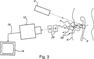
図3は、多重散乱光を除去するためにコリメータを用いたシステムからなる、本発明のまた別の実施の形態の概略図である。
図4は、反射画像の位相変調検出を行うシステムを示す概略図である。
図5は、本発明の原理による撮像ヘルメット装置の概略図である。
発明の説明
本発明は、血管の如くの解剖学的構造体の位置同定のためのシステムを提供するものであって、光源と、検査部位から反射された光照射を検出するイメージ検出器と、該イメージ検出器からイメージ情報を受けて表示するモニターとからなる。「光源」なる用語は、白色光光源の如くの多色光源に限らず、レーザ光光源の如くの単色光源をも含むものである。また、「イメージ検出器」なる用語は光を検出できるものであればどのようなものであってもよく、電荷結合装置型赤外線カメラ(CCD)、ビデオカメラ、液晶テレビ検出器などを含むものである。
所望に応じては、画像における解剖学的構造体とその周辺組織との間のコントラストを増強する素子類を本発明に設けても良い。ここでの「コントラスト増強素子」なる用語は、解剖学的構造体とその周辺組織との間の画像におけるコントラストを高めるものであれば一つの素子であっても良いし、又は、複数の素子の組合せからなるものであってもよく、素子としては、必要波長以外の光を除去するもの、目標組織部域における生物学的組織から多重散乱する光を減少させる、又は、目標部域近傍の生物学的組織からの多重散乱光を除去する素子などがある。このようなコントラスト増強素子としては、帯域フィルター、デジタル処理フィルター、コリメータ、光学偏光素子、光屈折結晶、デジタルフレーム取込み器、点滅撮像モニター(blink imaging monitor)、位相変調器、共焦点光学装置、外因性色素(exogenous dye)、血管変容処置(vascular modifying procedures)などが挙げられる。
反射光を検出するための本発明では、光源と反射イメージ検出器とを単一の一体構成の一部とすることができる。そのような単一の装置は取扱いが容易で、世話役としても当該装置を容易に保持できる、又は、装身することができ、ヘルメットの形で提供できる。後ほど詳述するように、単一の一体構成装置にできることから、ヘルメット装着者の視線に直接対応する、患者の内部域の三次元画像をリアルタイムで生成しうるヘルメットを構築することができる。この局面での本発明の変形例においては、単一の一体構成装置は、ヘルメットと、ヘルメットに着装した少なくとも一つの光源と少なくとも一つの撮像検出器とで構成されている。また、ヘルメットには、アイピースに内蔵させたモニターの如くの、ヘルメット装着者が見つめている解剖学的構造体のコントラストのついた画像を表示するモニターが含まれていても良い。好ましい実施の形態では、ヘルメットのそれぞれのアイピースに二つの撮像検出器を設けて、患者から反射される電磁波情報を検知するようにしている。光源としては所望により、鏡面反射を抑制すべくその一端が皮膚に押しつけられるようになっている光学フィルター束と接続されていても良い。得られた情報は三次元画像の生成に利用され、その後リアルタイムにて、ヘルメットのアイピースに内蔵されているモニターの如くのモニターに転送される。そのような実施の形態では、装着者の視線に対応して患者の際立った内部構造を眺めることができる。
本発明の別の実施の形態では、イメージ検出器と光照射源とは、目標部域に持ち込まれる単一の一体構成型走査装置の一部を構成している。この実施の形態では、単一の走査装置は、手持ち型走査器ないし可動走査器であってもよく、何れにしても携帯型モニターに取り付ける。そのような実施の形態なら、世話役による携帯走査が可能である。別の実施の形態としては、モニターそれ自体を走査器の一部を構成するようにしても良い。
本発明のもう一つの特徴に依れば、解剖学的構造体とその周辺組織とのコントラストを高めるのに種々の実施の形態を利用することができる点にある。その内の一つの実施の形態では、光源から、解剖学的構造体が吸収する波長を含む、例えば血液の場合では700〜900nmにわたる広範囲の波長を照射している。この光は目標構造体、例えば血管組織により吸収されるが、その周辺組織に吸収されるようなことはない。別の方法としては、照射光が検出器に到達する前の反射光路にフィルターを設けても良く、これにより多色ノイズ(polychromatic noise)を除去できる。その後、撮像検出器が画像モニターに信号を供給する。好ましい実施の形態での撮像検出器はCCDカメラである。
コントラスト増強に関わる別の実施の形態では、例えば700〜900nmの範囲の如くの所望範囲内の単一波長の照射光を発するレーザを照明光源として用いている。血管の如くの目標の解剖学的構造体を含む目標組織を光で照射する。すると、重要範囲内にある吸収されなかった光だけがイメージ検出器の方へと反射される。そのような実施の形態では、画像においてバックグランドノイズの出所となる他の多色光を減少させることができる。その他の解剖学的構造体を検出するのに特定の波長、例えばビリルビンの場合では730nm、脂肪の場合では1158nmと1210nm、血腫の場合では760nmの光を利用することができる。
別の実施の形態においては、偏光プリズムの如くの光学偏光素子を帯域フィルターに追加するか、又は、その代替に利用することもできる。組織に到達するに先立って光を偏光させることにより、反射光も組織に対して特定の平面に偏光させることができる。従って、検出器の直前に光学偏光素子を配置すれば、同一偏光作用において組織から反射した照射光を優先的に選択することができる。高度の散乱した光(ノイズ)と鏡面反射光とは、高度散乱光の場合ではランダムに偏光され、鏡面反射光の場合では入射光の偏光面とは異なった平面で圧倒的に偏光されることから、フィルターでカットすることができる。この偏光素子を用いた実施の形態は、透過照明光検出システムのみならず、反射光検出システムにも利用できる。
別の実施の形態においては、高度に散乱させられた反射光の大部分を除去するのにコリメータを用いている。この実施の形態の変形例としては、光源と検出器とをラスター形パターンで走査して、ラスター走査の時間にわたって画像を構築するようにしている。この変形例では、反射光を強く平行化する(collimation)ことができる。
別の実施の形態では、共焦点撮像システムを特定の目標深さのところに合焦させている。異なった深さと異なった位置からの光は光学系の焦点にコリメータを用いることで排除できる。すると、撮像すべき物体をラスター走査することにより画像を構築することができる。
また別の実施の形態にあっては、目標構造体には強く吸収されるが、その周辺組織には吸収されることのない波長と、ほぼ同一散乱効率で目標構造体とその周辺組織との両方により弱く吸収される波長との二つの波長にて組織を照射するようにしている。二つの画像が二値化(digitizing)フレーム取込み器により順次キャプチャされ、記憶した後に互いに差し引かれる。結果として得られる画像は、散乱光が差し引かれたわけだから、各画像に見られた散乱効果のない画像となる。変形例にあっては、二つの波長で目標を交互に照射してモニターに表示している。視聴者は交互にモニターに供給された画像を見ることになる。ヒトの目は光強度の比較的高速な変化に特に感じやすいことから、視聴者は高度に強調された解剖学的構造体の画像に対して感じやすい。この点滅撮像法では、信号の引き算を行うのに高価なデジタル電子処理を用いる必要性をなくしている。別の実施の形態では、光源照射光を、変調源をカー効果セルの如くの光位相変調器に接続することにより位相変調している。変調源はイメージ検出器をも変調させているから、検出器は入射光と同一変調状態を有する電磁照射だけを検知することになる。このような実施の形態では、画像形成に役立たない高度に散乱した光の位相をシフトさせることができる利点がある。従って、高度に散乱した光が検出されるようなことはない。別の実施の形態では、照射位相ではなくて、照射強度をダイオードレーザのパワー供給を変調させるとかして変えることにより、変調作用を達成している。(例えば、ニュージャージ州ニュートン所在のトーラボズ(ThorLabs)社製のS1011型ダイオードレーザ変調パワー供給装置の場合)。これらの変調作用を利用した実施の形態は、透過照明光検出システムのみならず、反射光検出システムにも利用できる。
画像コントラストを高める更にもう一つの実施の形態では、患者に外因性色素を与えて、目標の解剖学的構造体内に集まるようにしている。外因性色素は、周辺組織に対して特定波長の光をよく吸収する。色素を与える前の画像を取り出し、その後、色素を与えた後に取り出した画像から差し引く。このような方法では、両方の画像に共通した不要ノイズ成分を減じて、強調した画像だけを残すようにする。別の方法としては、操作者が前述の点滅撮像システムによる高度にコントラストが増強された画像だけを見ることができるように、これらの画像が交互して表示されるようにしても良い。別の実施の形態では、周辺組織に外因性色素が集まるようにする一方、目標の解剖学的構造体には集まらないようにして、画像のコントラストが醸し出されるようにしても良い。
別の実施の形態においては、イメージ検出器は、イリノイ州イタスカ所在のソニー電子社(Sony Electronics,Inc.)から入手可能な液晶テレビ型検出器であっても良い。液晶テレビ型検出器では位相感応検出が可能である。この点については、アライアンス・フォア・フォトニック・テクノロジー・インダストリアル・クォータリ(Alliance for Photonic Technology Industrial Quarterly)、Vol.3,No.2,p.3(1995年冬/春号)を参照のこと。この実施の形態では、検出器が同一周波数で変調された光のみをキャプチャして、残りの他の光を無視するように、光源は検出器と同期して位相変調されるようになっている。従って、光源からの入射光に対して位相がシフトした高度に散乱した光が除去されるのである。
また別の実施の形態においては、イメージ検出器は、全ての位相情報をキャプチャする液晶テレビ型検出器である。しかし、入射光を位相変調する代わりに、検出器は全ての位相の光をキャプチャして、位相情報を強度情報と共に、解剖学的構造体の三次元画像を構築するのに用いる装置へ供給するようになっている。位相情報をキャプチャすることにより、この実施の形態は三次元においてリアルタイムホログラフィを実現している。この三次元画像の実施の形態の変形例として、画像をキャプチャするイメージ検出器として、光屈折結晶ないしポリマー(例えば、カルフォルニア州カルバーシティ所在のCSKオプトロニックス社から入手可能なニオブ酸リチウム)を直接利用しても良い。すると、リアルタイムで結晶ないしポリマーを照射することでホログラム画像が得られる。別の方法としては、結晶ないしポリマーに液晶テレビ型検出器の出力が入力として供給されるようにしても良い。
好ましい実施の形態の詳細な説明
本発明の原理に従って構築した撮像システムを図1に示しているが、そのシステムは入射光4を生物学的組織6に対して照射する光源2からなり、入射光4の一部は目標の解剖学的構造体8に吸収されるまで生物学的組織を透過する。イメージ検出器12(例えば、Dage-MTI社から入手可能なCCD-72型カメラ)が、解剖学的構造体とは異なった吸収波長の、目標の解剖学的構造体を取り巻く組織から主として反射された反射光16を検出する。このイメージ検出器16はモニター14に対してビデオ信号18を供給するので、組織から反射した入射光の強度情報が画像としてモニターに表示される。多色光源を利用した場合では、目標構造体の撮像に有用な範囲外の波長は一つかそれ以上の帯域フィルター10によりカットされる。別の方法として、撮像検出器で、例えば電荷結合装置型赤外線カメラ(例えばニュージャージ州フェアチャイルド所在のエレクトロフィジックス社から入手可能なCCD1350-1赤外線CCDカメラと6300-00イメージ増強器)でそのようになっているように、有用な範囲の波長のみを検出するようにしても良い。また別の方法として、図2において説明した如くのリアルタイムデジタル型イメージ処理器(例えば、Dage-MTI社から入手可能なCSP-2000型プロセッサー)を利用して、多色光源から発する情報に乏しい波長をカットするようにしても良い。
本発明の別の実施の形態では、偏光フィルターの如くの光学偏光素子22a(マサチューセッツ州ホリストン所在のアーリング・エレクトロオプティックス社又はコネチカット州ストラトフォード所在のオリール社から入手可能)を、レーザないしその他の単色光源と一緒に用いている。単色光源は、例えばカリフォルニア州サニーヴァーレ所在のニュー・フォーカス社から入手可能な6124型レーザダイオードもしくはマサチューセッツ州アクトン所在のマイクレコール社から入手可能な「Micralase」、ミズーリ州セントルイス所在のマクドネル・ダグラス・エアロスペース社から入手可能なMDL-DLAW10などが挙げられる。偏光フィルターは、入射光を組織に対して特定の平面で偏光することにより、特異的に反射した光が別の偏光作用を受けたものとすることができる。検出器の直前における第2光学偏光素子22bは、光源から特異的に反射した光を優先的に選択する。イメージ情報を少しも持たない多重散乱光はランダム偏光されているのが通常であり、従って、第2光学偏光子22bを通過してイメージ検出器12に到達することはない。偏光フィルターは、光源2として多色光源を用いた場合に、帯域フィルター10や電荷結合装置型赤外線カメラ、図2のデジタル型イメージ処理器の何れか一つ、又はそれらの組合せと併用することもできる。光源2がレーザやその他の単色光源である場合では、これらの素子を組み合わせて利用することもできる。
本発明の更に別の実施の形態を図2に示すが、これはデジタル型イメージ処理器とフレーム取込み器24(Dage-MTI社から入手可能なCSP-2000の如くのもの)を備えた撮像システムである。この実施の形態においては、少なくとも二つの波長を投射する光源20で組織を照射するようになっている。好ましい実施の形態では、生物学的組織6は、組織を透過するが、目標の解剖学的構造体8には弱く吸収されるような波長で照射されるようにしている。血液のある血管の場合では、700nmから900nmの範囲、好ましくは800nm程度の波長で充分である。反射した画像は、デジタルフレーム取込み器を含むデジタル型イメージ処理器によりキャプチャされて保存される。次に、同一組織の部域を第2波長で照射するが、この第2波長は、組織散乱効率(tissue scattering efficiency)がほぼ同一となるように、前述の第1波長と周波数が近接している。しかし、この第2波長は目標の解剖学的構造体によりより弱く、或いは、より強く吸収されるようなものでなければならない。この第2画像はデジタル型イメージ処理器24によりキャプチャされて、前に保存した画像から差し引かれ、かくて、散乱による効果が除去された画像が得られると共に、これら二つの画像間での吸収特性の差が表示される。
二波長を利用したシステムの別の好ましい実施の形態では、デジタル型イメージ処理器24をなくしている。生物学的組織を二つの波長で照射し、それぞれの波長に対応する反射画像をモニター14で交互に表示することにより、目標の解剖学的構造体が順次交互に表示されることになる。ヒトの目は光強度の比較的高速な変化には敏感であるから、また、点滅撮像(blink imaging)として知られている心理的プロセスにより、目標構造体の輪郭を検出することができる。
本発明の更に別の実施の形態を図3に示すが、ここでは多重散乱光を除去するのにコリメータを利用している。図1に示したのと同一構成部品については同一符号で示している。この実施の形態では、多重散乱光子(multiply scattered photons)28がイメージ検出器12に到達するのを阻止するために少なくとも一つのコリメータ26を利用している。このようにして、強い平行化作用により、画像形成に有用ではないバックグランドノイズを減少させることができる。必要に応じて著しく強い平行化作用を利用すれば、光源とイメージ検出器とをラスター形パターンで走査する必要があり、その場合ではラスター走査時間にわたって画像が形成されることになる。コリメータは、図1と図2に示したコントラスト増強素子の考えられる組合せと一緒に利用することもできる。光源2が多色光源であれば、コリメータは帯域フィルター10、赤外線CCDの如くの選択イメージ検出器12、デジタル型イメージ処理器24、或いは、目的とする波長以外の反射光を除去するその他の装置と共に利用すべきである。
本発明のもう一つの実施の形態を図4に示すが、ここでは反射画像の位相変調検出(phase modulated detection)を行うようにしている。この実施の形態では、入射レーザ光が、回転式非球面光学素子(rotating aspheric optic)ないしカー効果セル(例えば、カリフォルニア州サンジョセ所在のアドバンスド・オプトロニック社、ロングモント社、ミードゥラーク・オプティック社、又は、オレゴン州ニルスボロ所在のニンズ・インストルメンツ社から入手可能)の如くの光位相変調器28を制御する変調源30により位相変調される。変調源30は、液晶ビデオテレビの如くの位相感応型撮像検出器32を制御している。従って、イメージ検出器は、入射光と同一変調状態を有する反射光を測定することになる。その他の光は測定から除外される。高度に散乱した光の位相がシフトされることから、その光も除去される。変調源30としては、一方が変調器28を制御し、他方が検出器32を制御する二つの独立した位相整合源(phase-matched source)で構成しても良い。
本発明のまた別の好ましい実施の形態を図5に示すが、ここでは目標の解剖学的構造体を双眼式拡大ステレオ撮像(binocular stereo imaging)システムとしている。この好ましい実施の形態では、二つの撮像検出器34a、34b(例えばイリノイ州パラタイン所在のFJW光学システム社から入手可能な、対物レンズ付き焦点合わせ用アイピースを備えた8900型赤外線感応式ビデオカメラ)を利用して目標組織からの反射光の二つの角度を検出することにより、画像内に三次元深度情報を組み込んでいる。この実施の形態の変形例では、ヘルメット40(例えばニューヨーク州スケーニーテレス所在のウェルチ-アレン社の「医療用ヘッドライト」)に光源38(例えばミズーリ州セントルイス所在のマクドネル・ダグラス・エアロスペース社のMDL-DLAW10型ダイオードレーザに、ニュージャージ州ニュートン所在のトーラボズ社製のLD1001型ドライバーを付加したもの)を装着すると共に、二つの撮像検出器34a、34bをも取り付けている。光源からの出力は、所望に応じて光学式ダイオードレーザコリメータ(diode laser collimation optics)(例えばニュージャージ州ニュートン所在のトーラボズ社製LT110P-B)で合焦させて、約20インチ離れたところに1ミリ径のスポットを形成するようにしても良い。入射光4は16a、16bで示したように目標組織から反射される。
好ましい実施の形態の変形例としては、全ての周囲光をカットするために、ビデオカメラの直前に帯域フィルター46a、46b(例えばバーモント州ブラットルボロ所在のオメガ・オプティック社製のBPシリーズ3Cavityなる中心波長を808nmとするフィルター)を配置しても良い。別の変形例としては、レーザ光源と組織との間及び二つのアイピースにリニア偏光フィルター(例えばコネチカット州ストラトフォード所在のオリール社製27805型フィルター)をそれぞれ配置して、散乱(ランダム偏光)光を除去することが考えられる。両検出器は、それぞれ僅かだけ異なった角度で反射した光を捕捉して立体効果を醸し出すようにしている。イメージ検出器40a、40bの出力情報はモニター14に送られて、処理された後に高度にコントラストが増強された組織部位の立体像が表示されるのである。この実施の形態の変形例においては、モニターは実際はヘルメットのアイピース44a、44bにあって、例えばイメージ検出器34a、34bに取り付けられているか、又は、その一部を構成していてもよく、これによりゴーグルの装着者が、あたかも目標の解剖学的構造体を取り巻く組織を眺めるかのように目標を検査することができる。
この実施の形態の別の変形例としては、これらの二つのイメージ検出器を外科手術器具の自動部品の上に装着することが考えられる。イメージ検出器34a、34bの出力は遠隔モニターに送られて、目標組織の三次元画像として表示される。そして外科手術器具を、位置応動型サーボモータを利用して遠隔操作する。従って、静脈穿刺の如くのある処置が操作者により遠隔操作で行われることになる。
別の方法としては、外因性色素が周辺組織に集まるようにし、目標の解剖学的構造体には集まらないようにする。例えば、インドシアン系緑(ICG)色素は組織が比較的透過性を呈しているのであれば、近800nmの波長を強く吸収する。フロック(Flock,S)らによる「インソシアン(insocyanine)系緑とパルス駆動式アレキサンドリアレーザを用いた血管の熱的損傷」、Lasers Med.Sci.,8:185-196(1993)。反射画像は、800nm照射源を用いて撮像する。その後、ICGを上流から注入して、二番目の画像を撮像する。最初の画像はデジタル処理器により記憶され、二番目の画像はデジタル処理器により差し引かれ、かくて前述したように結果が表示される。別の方法としては、操作者が前述した点滅撮像法を利用して、デジタル処理を行うことなく画像をモニターすることもできる。例えばヘマトポルフィリンの如くのその他の色素を利用することも可能である。
この実施の形態の変形例として、特定の抗原に対する単クローン系抗体を光吸収性発色団に結合させている。すると抗体は目標組織に結合する。そこで、目標部域を発色団が吸収する波長の光で照射して、それにより得られた画像を検出する。別の方法としては、抗体と結合した蛍光発色団(fluorophore)を励起する波長を利用して、蛍光発色団からの蛍光を検出するようにしても良い。この方法では、抗体技術(antibody technology)を介して結合し得る皮下病理学の画像が形成できる。たとえば、肝細胞表層抗原に対する単クローン系抗体を注入すると、本発明により肝臓の画像を形成することができる。そのような技法は、前述のシステムや組合せの何れにも利用できる。
この好ましい実施の形態のまた別の変形例としては、プラクないしコレステロールに親和力のある分子を血流に注入する方法がある。この場合、注入された分子は血管内のプラクに集まる。ハヤシ(Hayashi)らによる「モノ-L-アスパルチル-クロリンe6の蛍光発色スペクトル分析によるアテロームプラクの偶発的位置同定(Transadvential Localization of Atheromatous Plaques by Fluorescence Emission Spectrum Analysis of Mono-L-aspartyl-chlorin e6)」、27:1943-1947(1993)。この変形例では、照射波長は、薬の微分吸収特性(differential absorbance)ないし、別の方法として、特定の波長における薬の蛍光発色能(drug's capacity for fluorescence)に基づいて選定している。するとコントラスト画像が、適当な波長での照射後にイメージ検出器により検出される。
この好ましい実施の形態の更にまた別の変形例においては、血管変容処置を実施するに先立って血管の画像を撮像している。例えば、最初の画像の検出の後に血管に止血帯を宛うことで、血液密度を変えても良い。その後に二番目の画像を検出して最初の画像から差し引く。別の方法としては、最初の画像の検出後に皮膚表面に氷を宛って、血液の流を変えても良い。その後に後から得られた画像を最初の画像から差し引いて血管の輪郭像を形成する。
尚、当業者にはこのほかの改変や変形などが考えられるところであるが、本願発明者は、本願発明が当業界に対する貢献するところの範囲に入る全ての変形や改変などは、本願に対する特許において実施できるものと意図している。 Background of the Invention
The present invention relates to an imaging apparatus according to the front part of claim 1. More specifically, the present invention uses a device that is sensitive to the specific absorption and scattering characteristics of a target structure such as blood, for example, to analyze the anatomy of blood vessels in the human body.TargetThe present invention relates to a system for identifying a position of a structure. Furthermore, the present invention relates to a system and method for increasing the contrast between a target structure such as a blood vessel and the surrounding tissue.
In the United States, hundreds of thousands of medical procedures involving vascular puncture are performed every day. A procedure known as venipuncture is necessary for the injection of emergency fluids, blood components, anesthetic fluids during surgery, and blood collection for biological tests. In the case of injecting a drug product into a vein, the injection volume is often limited (a rate-limiting step). However, in normal patients, it is about half an hour. It takes more time in the case of obese and burn patients. The clinic and health care provider must be on standby until the patient is in the order of venipuncture, which is a huge financial burden on society as a whole, but if venipuncture cannot be performed immediately The patient's life may be threatened. In addition, if the clinician cannot identify the position of the blood vessel, puncture may be performed at a plurality of locations, but in this case, the disease rate may be increased.
The reason why venipuncture is sometimes difficult to perform is that the blood vessels are often relatively deep in the tissue, and under normal conditions there is an effect of optical absorption characteristics and optical scattering characteristics, which makes the blood vessels visible. This is because it is impossible. Furthermore, since the blood vessels are spastic or stenotic when they are tampered with, the situation is much worse. Therefore, health care providers must be able to see blood vessels in real time to reduce risk to patients, save time, and reduce the cost of treatment. Also, reducing the time associated with the procedure can limit the provider's contact with potentially contaminated puncture needles. Finally, if the vascular tissue can be viewed, important diagnostic and therapeutic information on thrombosis, cancer, vascular failure, etc. can be obtained.
In the middle of 1970, a device was devised that allowed the surgeon to see the blood vessels on the surface. The instrument consists of a visible light source, and when the light source is pressed against the skin, the subcutaneous tissue is transilluminated so that the apparent blood vessels are visible. This vascular illuminator utilizes different absorption characteristics of blood and tissue. While blood absorbs light of a certain wavelength strongly, fat and skin absorb light of a different wavelength, so health care providers can visually identify subcutaneous blood vessels with the naked eye. there were. However, since the transmission illuminator cannot obtain a sufficient contrast between the blood vessel and a tissue other than the tissue used for puncturing the blood vessel on the surface, such a transmission illuminator is not used. In addition, an improved version of the vascular illuminator was thermally damaging to the patient.
The failure of the transilluminator revealed that large contrasts are very important for medical professionals. As a result, some literatures suggest using illumination wavelengths that penetrate surface tissue to the depth of deep blood vessels and are absorbed in large quantities by blood. Regarding this point, for example, “A Review of the Optical Properties of Biological Tissues” by Cheong, WF, et al., IEEE Journ.Quant.Elec., 26: 2166-2185 (1990) , Have you been referred to. However, these documents do not disclose any means for effectively eliminating detection of light scattered from a region outside the blood vessel region (ie, off-angle light). There is also no disclosure of eliminating the detection of polychromatic white noise from ambient room light or multicolor light sources. Subsequent apparatuses only use a subtraction method that uses expensive digital processing methods and cumbersome computer analysis methods to remove unnecessary scattered light. Furthermore, these devices do not use the noise reduction method when a white light source is used, but rather use a monochromatic laser light source to reduce multicolor noise. Therefore, development of a contrast enhancement device that can be used together with a multicolor light source or that can be used in a multicolor clinical environment has been underway.
More importantly, an electromagnetic wave imaging device uses projected light rather than reflected light to construct an image. In such a system, the image detector and the light source are arranged on both sides of the patient, rather than side by side in a single unitary unit. Unfortunately, such an arrangement does not allow convenient illumination and detection from the same side as a single goggle or scanning device. Thus, manipulating several of these devices along with the patient requires multiple clinical personnel. In addition, the above-mentioned document has no suggestion of using not only reflected light but also scattered light to construct an image. On the contrary, in such an apparatus, since it is considered that scattered light does not include image information, it is configured to exclude all of these scattered light. Such an imaging apparatus is disclosed in, for example, US Pat. No. 4,817,622.
Disclosure of the invention
In the present invention, anatomy like a blood vesselTargetSystems and methods are provided that allow a structure to be viewed with great contrast to surrounding tissue. The present invention uses a reflected electromagnetic radiation wave that is specifically scattered from a target tissue.TargetThe purpose is to build an image of a structure.
Another object of the present invention is to detect anatomy by detecting electromagnetic radiation characteristics reflected from the target area.TargetIt is to generate a clear three-dimensional image of the structure.
Another object of the present invention is to provide irradiation and detection from the same side of a reflected electromagnetic wave used in a convenient integrated imaging apparatus.
Yet another object of the present invention is that a single monolithic helmet wearer can perform anatomy in a patient.TargetIt is an object of the present invention to provide a helmet-mounted imaging technique for the helmet, which allows an image of the structure to be always viewed following the movement of the wearer's head.
It is still another object of the present invention to provide a method and apparatus capable of performing venipuncture quickly, accurately and efficiently.
Another object of the present invention is to use anatomy for use in an imaging system.TargetThe object is to provide a method and apparatus for improving the contrast between a structure and its surrounding tissue.
These and other objects of the invention can be achieved by the features in claim 1 with respect to the imaging device according to the features in the front part of claim 1. Advantageous further embodiments are described in the dependent claims.
[Brief description of the drawings]
FIG. 1 is a schematic diagram of a basic imaging system constructed in accordance with the principles of the present invention.
FIG. 2 shows a light source that illuminates two different wavelength ranges;DigitalFIG. 6 is a schematic diagram of another embodiment of the present invention comprising an image processing device and a frame grabber that enhances image contrast.
FIG.MultipleFIG. 6 is a schematic diagram of yet another embodiment of the present invention comprising a system using a collimator to remove scattered light.
FIG. 4 is a schematic diagram showing a system for detecting phase modulation of a reflected image.
FIG. 5 is a schematic diagram of an imaging helmet device according to the principles of the present invention.
Description of the invention
The present invention provides a blood vessel-like anatomy.TargetA system for position identification of a structure, comprising: a light source; an image detector for detecting light irradiation reflected from an examination site; and a monitor for receiving and displaying image information from the image detector Consists of. The term “light source” includes not only a multicolor light source such as a white light source but also a monochromatic light source such as a laser light source. The term “image detector” may be anything as long as it can detect light, and includes a charge coupled device infrared camera (CCD), a video camera, a liquid crystal television detector, and the like.
Anatomy in the image, if desiredTargetElements that enhance the contrast between the structure and the surrounding tissue may be provided in the present invention. The term “contrast enhancing element” here refers to anatomyTargetOne element may be used as long as it increases the contrast in the image between the structure and the surrounding tissue, or a combination of a plurality of elements. Remove light other than wavelength, from biological tissue in the target tissue areaMultipleReduce scattered light, or from biological tissue near the target areaMultipleThere are elements that remove scattered light. Such contrast enhancement elements include bandpass filters, digital processing filters, collimators, optical polarizing elements, photorefractive crystals, digital frame capturers, blink imaging monitors, phase modulators, confocal optical devices, extrinsic factors Examples include exogenous dyes, vascular modifying procedures, and the like.
In the present invention for detecting reflected light, the light source and the reflected image detector can be part of a single integrated configuration. Such a single device is easy to handle and can be easily held or cared for as a caretaker and can be provided in the form of a helmet. As will be described in detail later, since a single integrated device can be formed, it is possible to construct a helmet that can generate a three-dimensional image of the patient's internal area that directly corresponds to the gaze of the helmet wearer in real time. In a variation of the invention in this aspect, the single monolithic component device is a helmet and, FI wore LumetWith at least one light sourceAnd at least one imaging detector. The helmet also looks like a monitor built into the eyepiece and the anatomy that the helmet wearer is looking at.TargetA monitor that displays an image with a contrast of the structure may be included. In a preferred embodiment, two imaging detectors are provided on each eyepiece of the helmet to detect electromagnetic wave information reflected from the patient. If desired, the light source may be connected to an optical filter bundle whose one end is pressed against the skin to suppress specular reflection. The obtained information is used to generate a three-dimensional image and then transferred in real time to a monitor such as a monitor built in the helmet eyepiece. In such an embodiment, the patient's outstanding internal structure can be viewed in response to the wearer's line of sight.
In another embodiment of the invention, the image detector and the light source form part of a single integrated scanning device that is brought into the target area. In this embodiment, the single scanning device may be a hand-held scanner or a movable scanner, and is attached to the portable monitor anyway. In such an embodiment, portable scanning by a caretaker is possible. In another embodiment, the monitor itself may form part of the scanner.
According to another feature of the invention, anatomyTargetVarious embodiments can be used to increase the contrast between the structure and the surrounding tissue. In one embodiment, from the light source, the anatomyTargetFor example, in the case of blood, a wide range of wavelengths ranging from 700 to 900 nm including the wavelength absorbed by the structure is irradiated. This light is absorbed by the target structure, eg, vascular tissue, but is not absorbed by the surrounding tissue. As another method, a filter may be provided in the reflected light path before the irradiation light reaches the detector, thereby removing polychromatic noise. Thereafter, the imaging detector supplies a signal to the image monitor. The imaging detector in the preferred embodiment is a CCD camera.
In another embodiment related to contrast enhancement, a laser that emits irradiation light having a single wavelength within a desired range such as a range of 700 to 900 nm is used as an illumination light source. Goal like a blood vesselofAnatomyTargetThe target tissue including the structure is irradiated with light. Then, only the unabsorbed light within the critical range is reflected towards the image detector. In such an embodiment, other polychromatic light that is the source of background noise in the image can be reduced. Other anatomyTargetSpecific wavelengths can be used to detect the structure, for example, 730 nm for bilirubin, 1158 nm and 1210 nm for fat, and 760 nm for hematoma.
In another embodiment, an optical polarizing element such as a polarizing prism can be added to the bandpass filter or used as an alternative. By polarizing the light prior to reaching the tissue, the reflected light can also be polarized in a specific plane relative to the tissue. Therefore, if an optical polarizing element is disposed immediately before the detector, irradiation light reflected from the tissue in the same polarization action can be preferentially selected. Highly scattered light (noise) and specularly reflected light are randomly polarized in the case of highly scattered light, and in the case of specularly reflected light, they are predominantly polarized on a plane different from the plane of polarization of the incident light. Can be cut with a filter. The embodiment using this polarizing element can be used not only for a transmitted illumination light detection system but also for a reflected light detection system.
In another embodiment, a collimator is used to remove most of the highly scattered reflected light. As a modification of this embodiment, the light source and the detector are scanned in a raster pattern, and an image is constructed over the raster scanning time. In this modification, the reflected light can be strongly collimated.
In another embodiment, the confocal imaging system is focused at a specific target depth. Light from different depths and different positions can be eliminated by using a collimator at the focal point of the optical system. Then, an image can be constructed by raster scanning the object to be imaged.
In another embodiment, the target structure and the surrounding tissue are absorbed with a wavelength that is strongly absorbed by the target structure but not absorbed by the surrounding tissue, and substantially the same scattering efficiency. The tissue is irradiated at two wavelengths, one that is weakly absorbed by both. Two images are captured sequentially by a digitizing frame grabber, stored and then subtracted from each other. As a resultimageSince the scattered light is subtracted, each image has no scattering effect. In the modification, the target is alternately irradiated with two wavelengths and displayed on the monitor. The viewer alternately sees the image supplied to the monitor. Because the human eye is particularly sensitive to relatively fast changes in light intensity, viewers are highly stressed anatomyTargetEasy to feel for the structure image. This blinking imaging method eliminates the need for expensive digital electronic processing to perform signal subtraction. In another embodiment, the light source illumination light is phase modulated by connecting the modulation source to an optical phase modulator such as a Kerr effect cell. Since the modulation source also modulates the image detector, the detector will only detect electromagnetic radiation having the same modulation state as the incident light. In such an embodiment, there is an advantage that the phase of highly scattered light that is not useful for image formation can be shifted. Therefore, highly scattered light is not detected. In another embodiment, the modulation effect is achieved by changing the illumination intensity rather than the illumination phase, such as by modulating the power supply of the diode laser. (For example, in the case of the S1011 diode laser modulated power supply manufactured by ThorLabs, Newton, NJ). Embodiments using these modulation actions can be used not only for transmitted illumination light detection systems but also for reflected light detection systems.
In yet another embodiment for enhancing image contrast, the patient is given exogenous dye to achieve the targetofAnatomyTargetIt gathers in the structure. Exogenous dyes absorb a certain wavelength of light well into surrounding tissues. The image prior to dyeing is removed and then subtracted from the image removed after dyeing. In such a method, unnecessary noise components common to both images are reduced, and only the emphasized image is left. Alternatively, these images may be displayed alternately so that the operator can see only the highly enhanced images from the flash imaging system described above. In another embodiment, the exogenous dye is collected in the surrounding tissue while the targetofAnatomyTargetThe contrast of the image may be brought out so as not to be collected in the structure.
In another embodiment, the image detector may be a liquid crystal television type detector available from Sony Electronics, Inc., Itasca, Illinois. A phase sensitive detection is possible with a liquid crystal television type detector. In this regard, please refer to Alliance for Photonic Technology Industrial Quarterly, Vol.3, No.2, p.3 (1995 winter / spring issue). In this embodiment, the light source is phase modulated in synchronism with the detector so that the detector only captures light modulated at the same frequency and ignores the remaining light. . Therefore, highly scattered light whose phase is shifted with respect to the incident light from the light source is removed.
In another embodiment, the image detector is a liquid crystal television type detector that captures all phase information. However, instead of phase modulating the incident light, the detector captures all phases of the light, and the phase information along with the intensity information along with the anatomyTargetIt is intended to be supplied to an apparatus used to construct a three-dimensional image of the structure. By capturing phase information, this embodiment implements real-time holography in three dimensions. As a modification of the embodiment of this three-dimensional image, as an image detector for capturing an image, a photorefractive crystal or polymer (for example, lithium niobate available from CSK Optronics, Inc., Calver City, Calif.) Is used. It may be used directly. Then, a hologram image is obtained by irradiating crystals or polymers in real time. As another method, the output of the liquid crystal television type detector may be supplied as an input to the crystal or polymer.
Detailed Description of the Preferred Embodiment
An imaging system constructed in accordance with the principles of the present invention is shown in FIG. 1, which comprises a light source 2 that irradiates a biological tissue 6 with incident light 4, a portion of which is the target.ofAnatomyTargetPermeates biological tissue until absorbed by the structure 8. Image detector 12 (eg CCD-72 camera available from Dage-MTI)TargetTarget of absorption wavelength different from the structureofAnatomyTargetThe reflected light 16 mainly reflected from the tissue surrounding the structure is detected. Since the
In another embodiment of the present invention, an optical
Yet another embodiment of the present invention is shown in FIG. 2, which is an imaging system comprising a digital image processor and a frame grabber 24 (such as CSP-2000 available from Dage-MTI). It is. In this embodiment, the tissue is irradiated with a
In another preferred embodiment of the dual wavelength system, the
Yet another embodiment of the present invention is shown in FIG.MultipleA collimator is used to remove scattered light. The same components as those shown in FIG. 1 are denoted by the same reference numerals. In this embodiment,MultipleAt least one
FIG. 4 shows another embodiment of the present invention. Here, the phase modulation detection of the reflected image is performed. In this embodiment, the incident laser light is a rotating aspheric optic or Kerr effect cell (e.g., Advanced Optronic, Longmont, Meudlark Optic, San Jose, Calif., Or Phase modulated by a
Another preferred embodiment of the present invention is shown in FIG.ofAnatomyTargetThe structure is a binocular stereo imaging system. In this preferred embodiment, two
As a variation of the preferred embodiment, a
As another variation of this embodiment, these two image detectors can be used for automatic parts of surgical instruments.aboveIt is possible to wear it.imageThe outputs of the
Another method is to allow the exogenous dye to collect in the surrounding tissue and targetofAnatomyTargetAvoid gathering in structures. For example, indocyanine green (ICG) dyes strongly absorb near 800 nm wavelengths if the tissue is relatively transmissive. “Insocy” by Flock, S et al.anine) Thermal damage to blood vessels using green and pulse-driven Alexandria lasers, Lasers Med. Sci., 8: 185-196 (1993). The reflected image is captured using an 800 nm irradiation source. Thereafter, ICG is injected from the upstream side to capture a second image. The first image is by a digital processorMemoryThe second image is then subtracted by the digital processor, thus displaying the result as described above. As another method, the operator can monitor the image without performing digital processing by using the blinking imaging method described above. For example, other dyes such as hematoporphyrin can be used.
As a modification of this embodiment,specificA monoclonal antibody against the antigen is bound to a light-absorbing chromophore. The antibody then binds to the target tissue. Therefore, the target area is irradiated with light having a wavelength that is absorbed by the chromophore, and an image obtained thereby is detected. As another method, the fluorescence from the fluorescent chromophore may be detected using the wavelength that excites the fluorophore bound to the antibody. In this way, images of subcutaneous pathology can be formed that can be coupled via antibody technology. For example, when a monoclonal antibody against hepatocyte surface antigen is injected, an image of the liver can be formed according to the present invention. Such techniques can be used in any of the systems and combinations described above.
Another variation of this preferred embodiment is a method of injecting molecules with an affinity for plaque or cholesterol into the bloodstream. In this case, the injected molecules collect in plaques in the blood vessels. Hayashi et al. “Transadvential Localization of Atheromatous Plaques by Fluorescence Emission Spectrum Analysis of Mono-L-aspartyl-chlorin e6” 27: 1943-1947 (1993). In this modification, the irradiation wavelength is selected based on the differential absorbance of the drug or, alternatively, based on the drug's capacity for fluorescence at a specific wavelength. The contrast image is then detected by the image detector after irradiation at the appropriate wavelength.
In yet another variation of this preferred embodiment, a blood vessel image is taken prior to performing the vascular transformation procedure. For example, the blood density may be changed by assigning a tourniquet to the blood vessel after detection of the first image. Thereafter, the second image is detected and subtracted from the first image. Alternatively, the blood flow may be changed by directing ice to the skin surface after detection of the first image. Thereafter, an image obtained later is subtracted from the initial image to form a blood vessel contour image.
It should be noted that other modifications and variations can be considered by those skilled in the art. However, the inventor of the present application shall consider all variations and modifications that fall within the scope of contribution of the present invention to the industry in the patent for the present application. It is intended to be implemented.
Claims (26)
上記光源からの光であって、目標の生物学的組織から反射された光を検出するイメージ検出器と、
目標の解剖学的構造体から直接反射されかつ1回散乱された上記光源からの光から、目標の解剖学的構造体以外の周囲の組織から反射された多重散乱光を減ずるための手段を含んでいるコントラスト増強素子と、
上記イメージ検出器から供給された解剖学的内部構造体の画像を表示するモニターとからなり、
前記光源と前記イメージ検出器とが単一の一体構成装置の一部を構成し、前記単一の一体構成装置がヘルメットからなる
撮像装置。A light source;
An image detector for detecting light from the light source reflected from the target biological tissue ;
From light from the light source being scattered directly reflected and once from anatomical structures of targets, means for reducing the multiple scattered light reflected from the surrounding non-anatomical structures of the target tissue A contrast enhancing element ,
A monitor that displays an image of the anatomical internal structure supplied from the image detector,
The imaging apparatus, wherein the light source and the image detector constitute a part of a single integrated device, and the single integrated device is a helmet .
前記コントラスト増強素子が、前記光源と前記生物学的組織との間の入射光の光路に設けられた第1光学偏光素子と、組織の非光源側と前記イメージ検出器との間の透過光の光路に設けられた第2光学偏光素子とを備えている撮像装置。The imaging apparatus according to claim 1,
The contrast enhancing element includes a first optical polarizing element provided in an optical path of incident light between the light source and the biological tissue, and transmitted light between the non-light source side of the tissue and the image detector. An imaging apparatus comprising: a second optical polarization element provided in the optical path.
前記コントラスト増強素子が、変調源と、該変調源に接続された光位相変調器とを備えている撮像装置。The imaging apparatus according to claim 1,
The imaging apparatus, wherein the contrast enhancing element includes a modulation source and an optical phase modulator connected to the modulation source.
前記コントラスト増強素子が、照射強度変調源を備えている撮像装置。The imaging apparatus according to claim 1,
An imaging apparatus in which the contrast enhancement element includes an irradiation intensity modulation source.
上記光源からの光であって、目標の生物学的組織から反射された光を検出するイメージ検出器と、An image detector for detecting light from the light source reflected from the target biological tissue;
目標の解剖学的構造体から直接反射されかつ1回散乱された上記光源からの光から、目標の解剖学的構造体以外の周囲の組織から反射された多重散乱光を減ずるための手段を含んでいるコントラスト増強素子とからなり、Means for subtracting multiple scattered light reflected from surrounding tissue other than the target anatomy from light from the light source directly reflected and scattered once from the target anatomy; Contrast enhancement element
前記光源と前記イメージ検出器とが単一の一体構成装置の一部を構成し、The light source and the image detector form part of a single integrated device;
前記単一の一体構成装置が外科手術器具の自動部品であるThe single integrated component is an automatic part of a surgical instrument
撮像装置。Imaging device.
Applications Claiming Priority (3)
| Application Number | Priority Date | Filing Date | Title |
|---|---|---|---|
| US08/483,480 | 1995-06-07 | ||
| US08/483,480 US6032070A (en) | 1995-06-07 | 1995-06-07 | Method and apparatus for detecting electro-magnetic reflection from biological tissue |
| PCT/US1996/007623 WO1996039925A1 (en) | 1995-06-07 | 1996-05-23 | Method and apparatus for detecting electro-magnetic reflection from biological tissue |
Publications (2)
| Publication Number | Publication Date |
|---|---|
| JPH11509748A JPH11509748A (en) | 1999-08-31 |
| JP3734508B2 true JP3734508B2 (en) | 2006-01-11 |
Family
ID=23920215
Family Applications (1)
| Application Number | Title | Priority Date | Filing Date |
|---|---|---|---|
| JP50070797A Expired - Fee Related JP3734508B2 (en) | 1995-06-07 | 1996-05-23 | Device for detecting electromagnetic reflected waves from biological tissue |
Country Status (11)
| Country | Link |
|---|---|
| US (3) | US6032070A (en) |
| EP (3) | EP1514510A1 (en) |
| JP (1) | JP3734508B2 (en) |
| AT (2) | ATE200020T1 (en) |
| AU (1) | AU706419B2 (en) |
| CA (1) | CA2223089C (en) |
| DE (2) | DE69612283T2 (en) |
| DK (1) | DK0830077T3 (en) |
| ES (1) | ES2156280T3 (en) |
| HK (1) | HK1032520A1 (en) |
| WO (1) | WO1996039925A1 (en) |
Families Citing this family (206)
| Publication number | Priority date | Publication date | Assignee | Title |
|---|---|---|---|---|
| US6230046B1 (en) * | 1995-05-16 | 2001-05-08 | The United States Of America As Represented By The Secretary Of The Air Force | System and method for enhanced visualization of subcutaneous structures |
| US6032070A (en) * | 1995-06-07 | 2000-02-29 | University Of Arkansas | Method and apparatus for detecting electro-magnetic reflection from biological tissue |
| CA2192036A1 (en) * | 1996-12-04 | 1998-06-04 | Harvey Lui | Fluorescence scope system for dermatologic diagnosis |
| EP0971624A1 (en) | 1997-03-13 | 2000-01-19 | Biomax Technologies, Inc. | Methods and apparatus for detecting the rejection of transplanted tissue |
| SE9701303L (en) * | 1997-04-09 | 1998-10-10 | Haakan Ugnell | Optical technique for identifying blood vessels on skin or organs |
| JP3831950B2 (en) | 1997-05-02 | 2006-10-11 | セイコーエプソン株式会社 | Communication device, transmitter, laser, biological communication device, reflected light detector, and pulse wave detection device |
| EP1925961B1 (en) * | 1997-06-30 | 2017-03-29 | Lucid, Inc. | Confocal imaging through thick dermal tissues |
| US6505059B1 (en) | 1998-04-06 | 2003-01-07 | The General Hospital Corporation | Non-invasive tissue glucose level monitoring |
| US20020091324A1 (en) * | 1998-04-06 | 2002-07-11 | Nikiforos Kollias | Non-invasive tissue glucose level monitoring |
| US7899518B2 (en) * | 1998-04-06 | 2011-03-01 | Masimo Laboratories, Inc. | Non-invasive tissue glucose level monitoring |
| US6728560B2 (en) | 1998-04-06 | 2004-04-27 | The General Hospital Corporation | Non-invasive tissue glucose level monitoring |
| US6353753B1 (en) | 1998-05-05 | 2002-03-05 | Stephen Thomas Flock | Optical imaging of deep anatomic structures |
| US6110106A (en) * | 1998-06-24 | 2000-08-29 | Biomax Technologies, Inc. | Endoscopes and methods relating to direct viewing of a target tissue |
| US7233346B1 (en) * | 1998-07-14 | 2007-06-19 | The United States Of America As Represented By The Secretary Of The Navy | Differential imaging method and system |
| CA2337871A1 (en) * | 1998-07-30 | 2000-02-10 | Yissum Research Development Company Of The Hebrew University Of Jerusalem | Optical mammography |
| US6424858B1 (en) * | 1998-11-12 | 2002-07-23 | John L. Williams | Apparatus and method for viewing vasculature of a human being |
| US6602274B1 (en) * | 1999-01-15 | 2003-08-05 | Light Sciences Corporation | Targeted transcutaneous cancer therapy |
| US20050182434A1 (en) | 2000-08-11 | 2005-08-18 | National Research Council Of Canada | Method and apparatus for performing intra-operative angiography |
| DK2910185T3 (en) * | 1999-09-24 | 2018-05-07 | Novadaq Tech Ulc | Method of Assessing Tissue Perfusion |
| IL132138A0 (en) * | 1999-09-29 | 2001-03-19 | Metranets Ltd | Method and apparatus for 3d scanning of the human body form |
| AU7551400A (en) * | 1999-09-29 | 2001-04-30 | Metranets Ltd. | Methods and apparatus for 3d scanning of the human body form |
| CA2385136C (en) * | 1999-10-01 | 2005-08-16 | John L. Larue | Camouflaged structure and method of camouflaging a structure |
| US7280866B1 (en) | 1999-10-06 | 2007-10-09 | National Research Council Of Canada | Non-invasive screening of skin diseases by visible/near-infrared spectroscopy |
| US6567682B1 (en) * | 1999-11-16 | 2003-05-20 | Carecord Technologies, Inc. | Apparatus and method for lesion feature identification and characterization |
| US6556858B1 (en) * | 2000-01-19 | 2003-04-29 | Herbert D. Zeman | Diffuse infrared light imaging system |
| US8078263B2 (en) * | 2000-01-19 | 2011-12-13 | Christie Medical Holdings, Inc. | Projection of subsurface structure onto an object's surface |
| US6495833B1 (en) * | 2000-01-20 | 2002-12-17 | Research Foundation Of Cuny | Sub-surface imaging under paints and coatings using early light spectroscopy |
| WO2001054580A1 (en) | 2000-01-27 | 2001-08-02 | National Research Council Of Canada | Visible-near infrared spectroscopy in burn injury assessment |
| AU2001259435A1 (en) * | 2000-05-03 | 2001-11-12 | Stephen T Flock | Optical imaging of subsurface anatomical structures and biomolecules |
| DE10059070C1 (en) * | 2000-11-28 | 2002-02-14 | Pulsion Medical Sys Ag | Device for determining tissue perfusion has source and expansion optics arranged in safety housing so only expanded beam of intensity within safety limits for persons near device emanates |
| US6735462B2 (en) * | 2000-12-21 | 2004-05-11 | Raytheon Company | Method and apparatus for infrared imaging in small passageways |
| US20050010114A1 (en) * | 2001-01-29 | 2005-01-13 | Yissum Research Development Company Of The Hebrew University Of Jerusalem | Optical mammography |
| US20020115922A1 (en) * | 2001-02-12 | 2002-08-22 | Milton Waner | Infrared assisted monitoring of a catheter |
| JP3663598B2 (en) * | 2001-06-04 | 2005-06-22 | 岩雄 岡田 | Blood vessel detection device |
| US20030018271A1 (en) * | 2001-07-02 | 2003-01-23 | Kimble Allan Wayne | Simplified and lightweight system for enhanced visualization of subcutaneous hemoglobin-containing structures |
| US7158660B2 (en) * | 2002-05-08 | 2007-01-02 | Gee Jr James W | Method and apparatus for detecting structures of interest |
| US20040015158A1 (en) * | 2002-07-19 | 2004-01-22 | To-Mu Chen | Transilluminator device |
| WO2004054439A2 (en) * | 2002-12-13 | 2004-07-01 | Ietmed Ltd. | Optical examination method and apparatus particularly useful for real-time discrimination of tumors from normal tissues during surgery |
| US20040215081A1 (en) * | 2003-04-23 | 2004-10-28 | Crane Robert L. | Method for detection and display of extravasation and infiltration of fluids and substances in subdermal or intradermal tissue |
| CA2533621C (en) * | 2003-06-20 | 2013-12-10 | The Texas A & M University System | Method and system for near-infrared fluorescence contrast-enhanced imaging with area illumination and area detection |
| US7190991B2 (en) * | 2003-07-01 | 2007-03-13 | Xenogen Corporation | Multi-mode internal imaging |
| US20050033145A1 (en) * | 2003-07-02 | 2005-02-10 | Graham John S. | Wearable tissue viability diagnostic unit |
| US20060235308A1 (en) * | 2003-08-08 | 2006-10-19 | Van Beek Michael C | System for dark-field imaging of target areas below an object surface |
| JP2007517211A (en) * | 2003-12-22 | 2007-06-28 | コーニンクレッカ フィリップス エレクトロニクス エヌ ヴィ | Apparatus and method for performing orthogonal polarization spectroscopic imaging (OPSI) |
| US20050157939A1 (en) * | 2004-01-16 | 2005-07-21 | Mark Arsenault | Processes, products and systems for enhancing images of blood vessels |
| US7532746B2 (en) * | 2004-01-16 | 2009-05-12 | Vue Tek Scientific, Llc | System and method for locating and accessing a blood vessel |
| EP1566142A1 (en) * | 2004-02-19 | 2005-08-24 | Nederlandse Organisatie Voor Toegepast-Natuurwetenschappelijk Onderzoek Tno | Imaging of buried structures |
| US7879054B2 (en) * | 2004-03-11 | 2011-02-01 | Boston Scientific Scimed, Inc. | System and method for tissue sampling and therapeutic treatment |
| US20060100523A1 (en) * | 2004-11-08 | 2006-05-11 | Ogle John S | Noninvasive blood vessel location device and method |
| US20060173351A1 (en) * | 2005-01-03 | 2006-08-03 | Ronald Marcotte | System and method for inserting a needle into a blood vessel |
| US20060173360A1 (en) * | 2005-01-07 | 2006-08-03 | Kalafut John F | Method for detection and display of extravasation and infiltration of fluids and substances in subdermal or intradermal tissue |
| DE102005001682A1 (en) * | 2005-01-13 | 2006-08-10 | Siemens Ag | Apparatus for visualizing a lesion of a body part labeled with a fluorescent dye |
| US20060155194A1 (en) * | 2005-01-13 | 2006-07-13 | Ronald Marcotte | Method for detecting occlusions and leakages in subcutaneous blood vessels |
| US20060241495A1 (en) * | 2005-03-23 | 2006-10-26 | Eastman Kodak Company | Wound healing monitoring and treatment |
| US20060239921A1 (en) | 2005-04-26 | 2006-10-26 | Novadaq Technologies Inc. | Real time vascular imaging during solid organ transplant |
| US7925332B2 (en) * | 2005-05-13 | 2011-04-12 | Infrared Imaging Systems, Inc. | Disposable light source patch for enhanced visualization of subcutaneous structures |
| JP5148054B2 (en) * | 2005-09-15 | 2013-02-20 | オリンパスメディカルシステムズ株式会社 | Imaging system |
| US8784336B2 (en) | 2005-08-24 | 2014-07-22 | C. R. Bard, Inc. | Stylet apparatuses and methods of manufacture |
| US20070122344A1 (en) | 2005-09-02 | 2007-05-31 | University Of Rochester Medical Center Office Of Technology Transfer | Intraoperative determination of nerve location |
| KR20080064155A (en) | 2005-10-14 | 2008-07-08 | 어플라이드 리써치 어쏘시에이츠 뉴질랜드 리미티드 | A method of monitoring a surface feature and apparatus therefor |
| US8478386B2 (en) | 2006-01-10 | 2013-07-02 | Accuvein Inc. | Practitioner-mounted micro vein enhancer |
| US10813588B2 (en) | 2006-01-10 | 2020-10-27 | Accuvein, Inc. | Micro vein enhancer |
| US11253198B2 (en) | 2006-01-10 | 2022-02-22 | Accuvein, Inc. | Stand-mounted scanned laser vein contrast enhancer |
| US8489178B2 (en) | 2006-06-29 | 2013-07-16 | Accuvein Inc. | Enhanced laser vein contrast enhancer with projection of analyzed vein data |
| US8838210B2 (en) | 2006-06-29 | 2014-09-16 | AccuView, Inc. | Scanned laser vein contrast enhancer using a single laser |
| US9854977B2 (en) | 2006-01-10 | 2018-01-02 | Accuvein, Inc. | Scanned laser vein contrast enhancer using a single laser, and modulation circuitry |
| US9492117B2 (en) | 2006-01-10 | 2016-11-15 | Accuvein, Inc. | Practitioner-mounted micro vein enhancer |
| US8255040B2 (en) | 2006-06-29 | 2012-08-28 | Accuvein, Llc | Micro vein enhancer |
| US11278240B2 (en) | 2006-01-10 | 2022-03-22 | Accuvein, Inc. | Trigger-actuated laser vein contrast enhancer |
| DE102006008990B4 (en) * | 2006-02-23 | 2008-05-21 | Atmos Medizintechnik Gmbh & Co. Kg | Method and arrangement for generating a signal corresponding to the opening state of the vocal folds of the larynx |
| US8649848B2 (en) * | 2006-03-28 | 2014-02-11 | The United States Of America, As Represented By The Secretary Of The Air Force | Synchronization of illumination source and sensor for improved visualization of subcutaneous structures |
| US20090318891A1 (en) * | 2006-04-05 | 2009-12-24 | Ronald Marcotte | Delivery device, system, and method for delivering substances into blood vessels |
| WO2007127339A2 (en) * | 2006-04-26 | 2007-11-08 | Tyco Healthcare Group Lp | Multi-stage microporation device |
| US8730321B2 (en) | 2007-06-28 | 2014-05-20 | Accuvein, Inc. | Automatic alignment of a contrast enhancement system |
| US8244333B2 (en) * | 2006-06-29 | 2012-08-14 | Accuvein, Llc | Scanned laser vein contrast enhancer |
| US8665507B2 (en) * | 2006-06-29 | 2014-03-04 | Accuvein, Inc. | Module mounting mirror endoscopy |
| US8463364B2 (en) | 2009-07-22 | 2013-06-11 | Accuvein Inc. | Vein scanner |
| US10238294B2 (en) | 2006-06-29 | 2019-03-26 | Accuvein, Inc. | Scanned laser vein contrast enhancer using one laser |
| US8594770B2 (en) | 2006-06-29 | 2013-11-26 | Accuvein, Inc. | Multispectral detection and presentation of an object's characteristics |
| US20080125663A1 (en) * | 2006-07-20 | 2008-05-29 | University Of Rochester Medical Center | Pre-And Intra-Operative Imaging of Testicular Torsion |
| US20080161744A1 (en) | 2006-09-07 | 2008-07-03 | University Of Rochester Medical Center | Pre-And Intra-Operative Localization of Penile Sentinel Nodes |
| US7917193B2 (en) * | 2006-10-11 | 2011-03-29 | The United States Of America As Represented By The Secretary Of The Air Force | Determining inserted catheter end location and orientation |
| US8388546B2 (en) | 2006-10-23 | 2013-03-05 | Bard Access Systems, Inc. | Method of locating the tip of a central venous catheter |
| US7794407B2 (en) | 2006-10-23 | 2010-09-14 | Bard Access Systems, Inc. | Method of locating the tip of a central venous catheter |
| US20140094666A1 (en) * | 2012-09-28 | 2014-04-03 | Elfi-Tech Ltd. | System and method for in vivo measurement of biological parameters |
| US20080194930A1 (en) * | 2007-02-09 | 2008-08-14 | Harris Melvyn L | Infrared-visible needle |
| US8068169B2 (en) * | 2007-02-26 | 2011-11-29 | General Scientific Corporation | Clip-on video camera system for medical, surgical and dental applications |
| US20090018414A1 (en) * | 2007-03-23 | 2009-01-15 | Mehrdad Toofan | Subcutanous Blood Vessels Imaging System |
| US7710569B2 (en) * | 2007-04-11 | 2010-05-04 | Remicalm, Llc | Headset mounted apparatus mounting a visor with interchangeable filter sets |
| JP5186791B2 (en) * | 2007-04-13 | 2013-04-24 | 住友電気工業株式会社 | Pore inspection device |
| RU2337608C1 (en) * | 2007-05-11 | 2008-11-10 | Общество с ограниченной ответственностью Научно-производственное предприятие "Лазма" | Diagnostic complex for measurement of medicobiological parameters of skin and mucosas in vivo |
| WO2009022692A1 (en) * | 2007-08-16 | 2009-02-19 | Shiro Amano | Meibomian gland observing device |
| US8781555B2 (en) | 2007-11-26 | 2014-07-15 | C. R. Bard, Inc. | System for placement of a catheter including a signal-generating stylet |
| US9521961B2 (en) | 2007-11-26 | 2016-12-20 | C. R. Bard, Inc. | Systems and methods for guiding a medical instrument |
| US10751509B2 (en) | 2007-11-26 | 2020-08-25 | C. R. Bard, Inc. | Iconic representations for guidance of an indwelling medical device |
| US10524691B2 (en) | 2007-11-26 | 2020-01-07 | C. R. Bard, Inc. | Needle assembly including an aligned magnetic element |
| EP2712547B1 (en) | 2007-11-26 | 2015-09-30 | C. R. Bard, Inc. | Integrated system for intravascular placement of a catheter |
| US10449330B2 (en) | 2007-11-26 | 2019-10-22 | C. R. Bard, Inc. | Magnetic element-equipped needle assemblies |
| US8849382B2 (en) | 2007-11-26 | 2014-09-30 | C. R. Bard, Inc. | Apparatus and display methods relating to intravascular placement of a catheter |
| US9649048B2 (en) * | 2007-11-26 | 2017-05-16 | C. R. Bard, Inc. | Systems and methods for breaching a sterile field for intravascular placement of a catheter |
| US20090281412A1 (en) * | 2007-12-18 | 2009-11-12 | Searete Llc, A Limited Liability Corporation Of The State Of Delaware | System, devices, and methods for detecting occlusions in a biological subject |
| US20090287120A1 (en) | 2007-12-18 | 2009-11-19 | Searete Llc, A Limited Liability Corporation Of The State Of Delaware | Circulatory monitoring systems and methods |
| US20090281413A1 (en) * | 2007-12-18 | 2009-11-12 | Searete Llc, A Limited Liability Corporation Of The State Of Delaware | Systems, devices, and methods for detecting occlusions in a biological subject |
| US20100036269A1 (en) * | 2008-08-07 | 2010-02-11 | Searete Llc, A Limited Liability Corporation Of The State Of Delaware | Circulatory monitoring systems and methods |
| US9717896B2 (en) * | 2007-12-18 | 2017-08-01 | Gearbox, Llc | Treatment indications informed by a priori implant information |
| US9672471B2 (en) * | 2007-12-18 | 2017-06-06 | Gearbox Llc | Systems, devices, and methods for detecting occlusions in a biological subject including spectral learning |
| US20090292213A1 (en) * | 2008-05-21 | 2009-11-26 | Searete Llc, A Limited Liability Corporation Of The State Of Delaware | Circulatory monitoring systems and methods |
| US20090163856A1 (en) * | 2007-12-19 | 2009-06-25 | Searete Llc, A Limited Liability Corporation Of The State Of Delaware | Treatment indications informed by a prior implant information |
| US8636670B2 (en) * | 2008-05-13 | 2014-01-28 | The Invention Science Fund I, Llc | Circulatory monitoring systems and methods |
| US20090292214A1 (en) * | 2008-05-22 | 2009-11-26 | Searete Llc, A Limited Liability Corporation Of The State Of Delaware | Circulatory monitoring systems and methods |
| US20100036263A1 (en) * | 2008-08-07 | 2010-02-11 | Searete Llc, A Limited Liability Corporation Of The State Of Delaware | Circulatory monitoring systems and methods |
| US8406860B2 (en) | 2008-01-25 | 2013-03-26 | Novadaq Technologies Inc. | Method for evaluating blush in myocardial tissue |
| US8478382B2 (en) | 2008-02-11 | 2013-07-02 | C. R. Bard, Inc. | Systems and methods for positioning a catheter |
| US20090214436A1 (en) | 2008-02-18 | 2009-08-27 | Washington University | Dichromic fluorescent compounds |
| JP5646147B2 (en) * | 2008-03-28 | 2014-12-24 | 公立大学法人大阪市立大学 | Method and apparatus for measuring a two-dimensional distribution |
| JP5534288B2 (en) * | 2008-04-02 | 2014-06-25 | 富士フイルム株式会社 | Signal processing apparatus, method of operating signal processing apparatus, and program |
| US10219742B2 (en) | 2008-04-14 | 2019-03-05 | Novadaq Technologies ULC | Locating and analyzing perforator flaps for plastic and reconstructive surgery |
| WO2009135178A2 (en) | 2008-05-02 | 2009-11-05 | Flower Robert W | Methods for production and use of substance-loaded erythrocytes (s-les) for observation and treatment of microvascular hemodynamics |
| JP4517004B2 (en) * | 2008-06-16 | 2010-08-04 | ノリー株式会社 | Injection needle guidance device |
| US8351667B2 (en) | 2008-08-15 | 2013-01-08 | Sti Medical Systems, Llc | Methods of contrast enhancement for images having blood vessel structures |
| WO2010022370A1 (en) | 2008-08-22 | 2010-02-25 | C.R. Bard, Inc. | Catheter assembly including ecg sensor and magnetic assemblies |
| US20100081916A1 (en) * | 2008-09-29 | 2010-04-01 | Searete Llc, A Limited Liability Corporation Of The State Of Delaware. | Histological facilitation systems and methods |
| US20100081926A1 (en) * | 2008-09-29 | 2010-04-01 | Searete Llc, A Limited Liability Corporation Of The State Of Delaware | Histological facilitation systems and methods |
| US20100081915A1 (en) * | 2008-09-29 | 2010-04-01 | Searete Llc, Alimited Liability Corporation Of The State Of Delaware | Histological facilitation systems and methods |
| US20100081927A1 (en) * | 2008-09-29 | 2010-04-01 | Searete Llc, A Limited Liability Corporation Of The State Of Delaware | Histological facilitation systems and methods |
| US20100081924A1 (en) * | 2008-09-29 | 2010-04-01 | Searete Llc, A Limited Liability Corporation Of The State Of Delaware | Histological facilitation systems and methods |
| US8437833B2 (en) | 2008-10-07 | 2013-05-07 | Bard Access Systems, Inc. | Percutaneous magnetic gastrostomy |
| US8254650B2 (en) * | 2009-02-27 | 2012-08-28 | General Electric Company | System and method for contrast enhancement of time-resolved fluorescence images |
| WO2010103440A1 (en) * | 2009-03-11 | 2010-09-16 | Koninklijke Philips Electronics N.V. | Irradiating an absorption contrast agent contained in a turbid medium |
| ES2345598B8 (en) | 2009-03-24 | 2013-02-12 | Hanscan Ip B.V. | THREE-DIMENSIONAL BIOMETRIC SCANNER |
| US10492671B2 (en) | 2009-05-08 | 2019-12-03 | Novadaq Technologies ULC | Near infra red fluorescence imaging for visualization of blood vessels during endoscopic harvest |
| US9532724B2 (en) | 2009-06-12 | 2017-01-03 | Bard Access Systems, Inc. | Apparatus and method for catheter navigation using endovascular energy mapping |
| US9445734B2 (en) | 2009-06-12 | 2016-09-20 | Bard Access Systems, Inc. | Devices and methods for endovascular electrography |
| RU2691318C2 (en) | 2009-06-12 | 2019-06-11 | Бард Аксесс Системс, Инк. | Method for positioning catheter end |
| US8311615B2 (en) * | 2009-07-09 | 2012-11-13 | Becton, Dickinson And Company | System and method for visualizing needle entry into a body |
| US8498694B2 (en) * | 2009-07-13 | 2013-07-30 | Entrotech, Inc. | Subcutaneous access device and related methods |
| US9061109B2 (en) | 2009-07-22 | 2015-06-23 | Accuvein, Inc. | Vein scanner with user interface |
| EP2517622A3 (en) | 2009-09-29 | 2013-04-24 | C. R. Bard, Inc. | Stylets for use with apparatus for intravascular placement of a catheter |
| US11103213B2 (en) * | 2009-10-08 | 2021-08-31 | C. R. Bard, Inc. | Spacers for use with an ultrasound probe |
| JP5495718B2 (en) * | 2009-11-04 | 2014-05-21 | キヤノン株式会社 | Subject information acquisition device |
| US9220412B2 (en) * | 2009-11-19 | 2015-12-29 | Modulated Imaging Inc. | Method and apparatus for analysis of turbid media via single-element detection using structured illumination |
| JP2013518676A (en) | 2010-02-02 | 2013-05-23 | シー・アール・バード・インコーポレーテッド | Apparatus and method for locating catheter navigation and tip |
| WO2011116347A1 (en) * | 2010-03-19 | 2011-09-22 | Quickvein, Inc. | Apparatus and methods for imaging blood vessels |
| EP2575611B1 (en) | 2010-05-28 | 2021-03-03 | C. R. Bard, Inc. | Apparatus for use with needle insertion guidance system |
| ES2864665T3 (en) | 2010-05-28 | 2021-10-14 | Bard Inc C R | Apparatus for use with needle insertion guidance system |
| JP2013527469A (en) * | 2010-06-03 | 2013-06-27 | コーニンクレッカ フィリップス エレクトロニクス エヌ ヴィ | Apparatus and method for measuring a tissue sample such as bilirubin using Brewster's angle |
| EP2603145A2 (en) | 2010-08-09 | 2013-06-19 | C.R. Bard, Inc. | Support and cover structures for an ultrasound probe head |
| EP2605699A4 (en) | 2010-08-20 | 2015-01-07 | Bard Inc C R | Reconfirmation of ecg-assisted catheter tip placement |
| US8586924B2 (en) * | 2010-09-13 | 2013-11-19 | Lawrence Livermore National Security, Llc | Enhancement of the visibility of objects located below the surface of a scattering medium |
| EP2632360A4 (en) | 2010-10-29 | 2014-05-21 | Bard Inc C R | Bioimpedance-assisted placement of a medical device |
| JP4768079B1 (en) * | 2010-11-15 | 2011-09-07 | 龍貴 大西 | Blood vessel display device |
| US9066657B2 (en) | 2010-11-23 | 2015-06-30 | General Electric Company | Methods and systems of optical imaging for target detection in a scattering medium |
| BR112013030348A2 (en) | 2011-07-06 | 2017-08-01 | Bard Inc C R | method for determining a length of a medical component for use with an ultrasound imaging system including a probe; method for determining a needle length by a needle guidance system; and needle length determination system for an ultrasound imaging device including an ultrasound probe |
| USD724745S1 (en) | 2011-08-09 | 2015-03-17 | C. R. Bard, Inc. | Cap for an ultrasound probe |
| USD699359S1 (en) | 2011-08-09 | 2014-02-11 | C. R. Bard, Inc. | Ultrasound probe head |
| WO2013023037A2 (en) * | 2011-08-09 | 2013-02-14 | Lemm Technologies, Llc | Device and method for measuring an analyte under the nail |
| US9211107B2 (en) | 2011-11-07 | 2015-12-15 | C. R. Bard, Inc. | Ruggedized ultrasound hydrogel insert |
| US9179844B2 (en) | 2011-11-28 | 2015-11-10 | Aranz Healthcare Limited | Handheld skin measuring or monitoring device |
| EP3553075A1 (en) | 2012-01-23 | 2019-10-16 | Washington University | Goggle imaging systems and methods |
| US11399898B2 (en) | 2012-03-06 | 2022-08-02 | Briteseed, Llc | User interface for a system used to determine tissue or artifact characteristics |
| US8897522B2 (en) * | 2012-05-30 | 2014-11-25 | Xerox Corporation | Processing a video for vascular pattern detection and cardiac function analysis |
| EP2861153A4 (en) | 2012-06-15 | 2016-10-19 | Bard Inc C R | Apparatus and methods for detection of a removable cap on an ultrasound probe |
| US10278585B2 (en) | 2012-06-21 | 2019-05-07 | Novadaq Technologies ULC | Quantification and analysis of angiography and perfusion |
| US9072426B2 (en) | 2012-08-02 | 2015-07-07 | AccuVein, Inc | Device for detecting and illuminating vasculature using an FPGA |
| US9912847B1 (en) * | 2012-09-25 | 2018-03-06 | Amazon Technologies, Inc. | Image capture guidance to reduce specular reflection effects |
| WO2014074720A1 (en) | 2012-11-07 | 2014-05-15 | Modulated Imaging, Inc. | Efficient modulated imaging |
| US10376148B2 (en) | 2012-12-05 | 2019-08-13 | Accuvein, Inc. | System and method for laser imaging and ablation of cancer cells using fluorescence |
| WO2014094173A1 (en) * | 2012-12-20 | 2014-06-26 | Lanzo Vittorio F | Handheld venipuncture-assisting device |
| WO2014183387A1 (en) * | 2013-05-13 | 2014-11-20 | 执鼎医疗科技江苏有限公司 | Vascular image positioning system |
| WO2014204675A1 (en) * | 2013-06-18 | 2014-12-24 | Lawrence Livermore National Security, Llc | Imaging system and method for enhanced visualization of near surface vascular structures |
| ITFI20130255A1 (en) | 2013-10-23 | 2015-04-24 | Insono S R L | "DEVICE FOR NON-INVASIVE DETECTION OF PREDETERMINED ORGANIC STRUCTURES" |
| EP4071581A1 (en) * | 2013-11-29 | 2022-10-12 | Motiv Inc. | Wearable computing device |
| WO2015120256A2 (en) | 2014-02-06 | 2015-08-13 | C.R. Bard, Inc. | Systems and methods for guidance and placement of an intravascular device |
| WO2015148504A1 (en) | 2014-03-25 | 2015-10-01 | Briteseed Llc | Vessel detector and method of detection |
| US9659205B2 (en) | 2014-06-09 | 2017-05-23 | Lawrence Livermore National Security, Llc | Multimodal imaging system and method for non-contact identification of multiple biometric traits |
| US10599932B2 (en) | 2014-06-09 | 2020-03-24 | Lawrence Livermore National Security, Llc | Personal electronic device for performing multimodal imaging for non-contact identification of multiple biometric traits |
| WO2016049756A1 (en) | 2014-09-29 | 2016-04-07 | Novadaq Technologies Inc. | Imaging a target fluorophore in a biological material in the presence of autofluorescence |
| US9486128B1 (en) * | 2014-10-03 | 2016-11-08 | Verily Life Sciences Llc | Sensing and avoiding surgical equipment |
| AU2014408488B2 (en) | 2014-10-09 | 2019-07-18 | Stryker European Operations Limited | Quantification of absolute blood flow in tissue using fluorescence-mediated photoplethysmography |
| CN104337524A (en) * | 2014-10-27 | 2015-02-11 | 王炎 | Blood collection container |
| US10973584B2 (en) | 2015-01-19 | 2021-04-13 | Bard Access Systems, Inc. | Device and method for vascular access |
| US10820838B2 (en) | 2015-02-19 | 2020-11-03 | Briteseed, Llc | System for determining vessel size using light absorption |
| WO2016134330A1 (en) | 2015-02-19 | 2016-08-25 | Briteseed Llc | System and method for determining vessel size and/or edge |
| IL237995A0 (en) * | 2015-03-29 | 2015-11-30 | Abraham Aharoni | Device for visual vein location |
| WO2016179350A1 (en) | 2015-05-06 | 2016-11-10 | Washington University | Compounds having rd targeting motifs and methods of use thereof |
| US9690119B2 (en) | 2015-05-15 | 2017-06-27 | Vertical Optics, LLC | Wearable vision redirecting devices |
| IL244255A (en) | 2016-02-23 | 2017-04-30 | Vertical Optics Llc | Wearable vision redirecting devices |
| US10349890B2 (en) | 2015-06-26 | 2019-07-16 | C. R. Bard, Inc. | Connector interface for ECG-based catheter positioning system |
| WO2017062720A1 (en) | 2015-10-08 | 2017-04-13 | Briteseed Llc | System and method for determining vessel size |
| US11000207B2 (en) | 2016-01-29 | 2021-05-11 | C. R. Bard, Inc. | Multiple coil system for tracking a medical device |
| US10013527B2 (en) | 2016-05-02 | 2018-07-03 | Aranz Healthcare Limited | Automatically assessing an anatomical surface feature and securely managing information related to the same |
| JP7058642B2 (en) | 2016-08-30 | 2022-04-22 | ブライトシード・エルエルシー | A system for compensating for angular displacement in the irradiation pattern |
| US20180133411A1 (en) * | 2016-11-14 | 2018-05-17 | Xiang Yu | Systems and Methods for Detecting and Visualizing Blood Vessels |
| US11116407B2 (en) | 2016-11-17 | 2021-09-14 | Aranz Healthcare Limited | Anatomical surface assessment methods, devices and systems |
| EP3580609B1 (en) | 2017-02-10 | 2023-05-24 | Stryker European Operations Limited | Open-field handheld fluorescence imaging systems and methods |
| US11903723B2 (en) | 2017-04-04 | 2024-02-20 | Aranz Healthcare Limited | Anatomical surface assessment methods, devices and systems |
| WO2018207602A1 (en) * | 2017-05-09 | 2018-11-15 | シンクロア株式会社 | Head-mounted lighting device |
| CN109247910B (en) * | 2017-07-12 | 2020-12-15 | 京东方科技集团股份有限公司 | Blood vessel display device and blood vessel display method |
| WO2019050928A1 (en) | 2017-09-05 | 2019-03-14 | Briteseed, Llc | System and method used to determine tissue and/or artifact characteristics |
| WO2019126633A1 (en) | 2017-12-22 | 2019-06-27 | Briteseed, Llc | A compact system used to determine tissue or artifact characteristics |
| JP2020014645A (en) * | 2018-07-25 | 2020-01-30 | インフォコム株式会社 | Photosensitive substance captured image processing system and photosensitive substance imaging method |
| WO2020081373A1 (en) | 2018-10-16 | 2020-04-23 | Bard Access Systems, Inc. | Safety-equipped connection systems and methods thereof for establishing electrical connections |
| US20200288965A1 (en) * | 2019-03-11 | 2020-09-17 | Spring Biomed Vision Ltd. | System and method for enhanced imaging of biological tissue |
| US20210059746A1 (en) * | 2019-08-30 | 2021-03-04 | Biosense Webster (Israel) Ltd. | Ent guidewire |
| EP4072598A4 (en) | 2019-12-13 | 2024-02-21 | Washington University St Louis | Near infrared fluorescent dyes, formulations and related methods |
| JP2023511407A (en) | 2020-01-22 | 2023-03-17 | フォトニック メディカル インク. | Open-field multi-mode depth-sensing calibrated digital loupe |
Family Cites Families (34)
| Publication number | Priority date | Publication date | Assignee | Title |
|---|---|---|---|---|
| DE266024C (en) * | ||||
| US4395731A (en) * | 1981-10-16 | 1983-07-26 | Arnold Schoolman | Television microscope surgical method and apparatus therefor |
| JPS58141135A (en) * | 1981-10-20 | 1983-08-22 | 富士写真フイルム株式会社 | Image transmitting system of endoscope using solid image sensor |
| US4467812A (en) * | 1982-07-19 | 1984-08-28 | Spectrascan, Inc. | Transillumination apparatus |
| JPS5940830A (en) * | 1982-08-31 | 1984-03-06 | 浜松ホトニクス株式会社 | Apparatus for diagnosis of cancer using laser beam pulse |
| GB2150387A (en) * | 1983-10-14 | 1985-06-26 | Secr Defence | Thermal imager |
| US4570638A (en) * | 1983-10-14 | 1986-02-18 | Somanetics Corporation | Method and apparatus for spectral transmissibility examination and analysis |
| US4948974A (en) * | 1984-06-25 | 1990-08-14 | Nelson Robert S | High resolution imaging apparatus and method for approximating scattering effects |
| US4621283A (en) * | 1984-08-27 | 1986-11-04 | Designs For Vision, Inc. | Head-mounted coaxial image system for surgeons |
| US4817622A (en) * | 1986-07-22 | 1989-04-04 | Carl Pennypacker | Infrared imager for viewing subcutaneous location of vascular structures and method of use |
| US4891829A (en) * | 1986-11-19 | 1990-01-02 | Exxon Research And Engineering Company | Method and apparatus for utilizing an electro-optic detector in a microtomography system |
| US4945239A (en) * | 1989-03-29 | 1990-07-31 | Center For Innovative Technology | Early detection of breast cancer using transillumination |
| US5039198A (en) * | 1989-08-02 | 1991-08-13 | Vanbeek Allen L | Stereoscopic microsurgery system |
| KR920007329B1 (en) * | 1990-05-30 | 1992-08-31 | 금성사 주식회사 | Optical apparatus for finger printers recognition |
| US5305759A (en) * | 1990-09-26 | 1994-04-26 | Olympus Optical Co., Ltd. | Examined body interior information observing apparatus by using photo-pulses controlling gains for depths |
| US5213105A (en) * | 1990-12-04 | 1993-05-25 | Research Corporation Technologies, Inc. | Frequency domain optical imaging using diffusion of intensity modulated radiation |
| GB9027718D0 (en) * | 1990-12-20 | 1991-02-13 | Emi Plc Thorn | Fingerprint imaging |
| CA2042075C (en) * | 1991-05-08 | 2001-01-23 | Branko Palcic | Endoscopic imaging system |
| SE468925B (en) * | 1991-08-22 | 1993-04-19 | Gert Nilsson | A METHOD AND APPARATUS SHOULD REDUCE THE DISTANCE-BASED FACTOR IN Saturation of STRAIGHT MOVEMENTS WITH AN IMAGING LASER-DOUBLE TECHNIQUE, SPECIFICALLY IN SEATING BLOOD PERFUSION THROUGH |
| US5279297A (en) * | 1991-09-20 | 1994-01-18 | Trustees Of The University Of Pennsylvania | Method and apparatus for oxygen mapping |
| US5348018A (en) * | 1991-11-25 | 1994-09-20 | Alfano Robert R | Method for determining if tissue is malignant as opposed to non-malignant using time-resolved fluorescence spectroscopy |
| US6002958A (en) * | 1992-12-24 | 1999-12-14 | Dynamics Imaging, Inc. | Method and apparatus for diagnostics of internal organs |
| GB2276732B (en) * | 1993-03-31 | 1995-12-13 | Central Research Lab Ltd | Fingerprint imaging |
| AU5173893A (en) * | 1993-05-04 | 1994-11-21 | Chang-Xing Liu | Method and apparatus for examining tissue by transillumination using near infrared light |
| US5383452A (en) * | 1993-07-01 | 1995-01-24 | Buchert; Janusz | Method, apparatus and procedure for non-invasive monitoring blood glucose by measuring the polarization ratio of blood luminescence |
| CA2131060C (en) * | 1993-09-03 | 2005-03-15 | Hiroshi Yamamoto | Non-invasive blood analyzer and method using the same |
| US5515864A (en) * | 1994-04-21 | 1996-05-14 | Zuckerman; Ralph | Method and apparatus for the in vivo measurement of oxygen concentration levels by the indirect determination of fluoescence lifetime |
| JP3364323B2 (en) * | 1994-05-17 | 2003-01-08 | 謙 石原 | Non-invasive blood analyzer |
| US5519208A (en) * | 1994-09-29 | 1996-05-21 | Esparza; Joel | Infrared aided method and apparatus for venous examination |
| US5625458A (en) * | 1994-11-10 | 1997-04-29 | Research Foundation Of City College Of New York | Method and system for imaging objects in turbid media using diffusive fermat photons |
| US6032070A (en) * | 1995-06-07 | 2000-02-29 | University Of Arkansas | Method and apparatus for detecting electro-magnetic reflection from biological tissue |
| US5833613A (en) * | 1996-09-27 | 1998-11-10 | Advanced Technology Laboratories, Inc. | Ultrasonic diagnostic imaging with contrast agents |
| EP0957750A1 (en) * | 1995-10-23 | 1999-11-24 | Cytometrics, Inc. | Method and apparatus for reflected imaging analysis |
| US5647368A (en) * | 1996-02-28 | 1997-07-15 | Xillix Technologies Corp. | Imaging system for detecting diseased tissue using native fluorsecence in the gastrointestinal and respiratory tract |
-
1995
- 1995-06-07 US US08/483,480 patent/US6032070A/en not_active Expired - Lifetime
-
1996
- 1996-05-23 EP EP04027794A patent/EP1514510A1/en not_active Withdrawn
- 1996-05-23 AU AU59296/96A patent/AU706419B2/en not_active Ceased
- 1996-05-23 WO PCT/US1996/007623 patent/WO1996039925A1/en active IP Right Grant
- 1996-05-23 CA CA002223089A patent/CA2223089C/en not_active Expired - Fee Related
- 1996-05-23 DE DE69612283T patent/DE69612283T2/en not_active Expired - Lifetime
- 1996-05-23 EP EP00120668A patent/EP1066791B1/en not_active Expired - Lifetime
- 1996-05-23 ES ES96916603T patent/ES2156280T3/en not_active Expired - Lifetime
- 1996-05-23 DK DK96916603T patent/DK0830077T3/en active
- 1996-05-23 AT AT96916603T patent/ATE200020T1/en active
- 1996-05-23 JP JP50070797A patent/JP3734508B2/en not_active Expired - Fee Related
- 1996-05-23 EP EP96916603A patent/EP0830077B1/en not_active Expired - Lifetime
- 1996-05-23 DE DE69633946T patent/DE69633946T2/en not_active Expired - Lifetime
- 1996-05-23 AT AT00120668T patent/ATE282985T1/en active
-
2000
- 2000-01-07 US US09/479,755 patent/US6272374B1/en not_active Expired - Lifetime
-
2001
- 2001-05-03 HK HK01103122A patent/HK1032520A1/en not_active IP Right Cessation
- 2001-06-05 US US09/875,497 patent/US7006861B2/en not_active Expired - Fee Related
Also Published As
| Publication number | Publication date |
|---|---|
| DE69612283D1 (en) | 2001-05-03 |
| HK1032520A1 (en) | 2001-07-27 |
| ES2156280T3 (en) | 2001-06-16 |
| JPH11509748A (en) | 1999-08-31 |
| ATE282985T1 (en) | 2004-12-15 |
| ATE200020T1 (en) | 2001-04-15 |
| EP0830077A1 (en) | 1998-03-25 |
| CA2223089C (en) | 2005-07-12 |
| EP0830077B1 (en) | 2001-03-28 |
| US20010027273A1 (en) | 2001-10-04 |
| WO1996039925A1 (en) | 1996-12-19 |
| EP1066791A3 (en) | 2001-10-17 |
| AU5929696A (en) | 1996-12-30 |
| CA2223089A1 (en) | 1996-12-19 |
| DE69633946T2 (en) | 2006-03-02 |
| DE69633946D1 (en) | 2004-12-30 |
| US6272374B1 (en) | 2001-08-07 |
| EP1066791B1 (en) | 2004-11-24 |
| DE69612283T2 (en) | 2001-11-08 |
| EP1066791A2 (en) | 2001-01-10 |
| AU706419B2 (en) | 1999-06-17 |
| DK0830077T3 (en) | 2001-06-18 |
| US7006861B2 (en) | 2006-02-28 |
| EP1514510A1 (en) | 2005-03-16 |
| US6032070A (en) | 2000-02-29 |
Similar Documents
| Publication | Publication Date | Title |
|---|---|---|
| JP3734508B2 (en) | Device for detecting electromagnetic reflected waves from biological tissue | |
| US6353753B1 (en) | Optical imaging of deep anatomic structures | |
| JP6285522B2 (en) | Perfusion assessment multi-modality optical medical device | |
| US6305804B1 (en) | Non-invasive measurement of blood component using retinal imaging | |
| CN105848566B (en) | The equipment of Non-invasive detection for predetermined biological structure | |
| JP5911196B2 (en) | Photoacoustic imaging device | |
| EP1810610A1 (en) | Method and apparatus for analyzing characteristic information of object with the use of mutual interaction between ultrasound wave and light | |
| US20020016533A1 (en) | Optical imaging of subsurface anatomical structures and biomolecules | |
| EP2359745A1 (en) | Method and device for multi-spectral photonic imaging | |
| WO2001050955A1 (en) | Improved endoscopic imaging and treatment of anatomic structures | |
| US20050194537A1 (en) | Integrated multi-spectral imaging systems and methods of tissue analyses using same | |
| CN102894960A (en) | Transmission-type hand back vein three-dimensional infrared imager | |
| WO2006014334A2 (en) | Systems and methods for localizing vascular architecture, and evaluation and monitoring of functional behavior of same | |
| WO1996021938A1 (en) | Video-rate confocal scanning laser microscope | |
| CN114300095A (en) | Image processing apparatus, image processing method, image processing device, image processing apparatus, and storage medium | |
| KR101610837B1 (en) | Photoacoustic imaging system for diagnosis animals of the ophthalmic diseases | |
| KR20150031874A (en) | Microscope system and method of providing augmented reality image using microscope system | |
| WO2013062067A1 (en) | Object information acquiring apparatus and control method for controlling the same | |
| WO2001078589A1 (en) | Non-invasive measurement of blood components using retinal imaging | |
| AU2002300219B2 (en) | Method and Apparatus for Detecting Electro-magnetic Reflection from Biological Tissue |
Legal Events
| Date | Code | Title | Description |
|---|---|---|---|
| A131 | Notification of reasons for refusal |
Free format text: JAPANESE INTERMEDIATE CODE: A131 Effective date: 20041102 |
|
| A601 | Written request for extension of time |
Free format text: JAPANESE INTERMEDIATE CODE: A601 Effective date: 20050202 |
|
| A602 | Written permission of extension of time |
Free format text: JAPANESE INTERMEDIATE CODE: A602 Effective date: 20050318 |
|
| A521 | Request for written amendment filed |
Free format text: JAPANESE INTERMEDIATE CODE: A523 Effective date: 20050502 |
|
| TRDD | Decision of grant or rejection written | ||
| A01 | Written decision to grant a patent or to grant a registration (utility model) |
Free format text: JAPANESE INTERMEDIATE CODE: A01 Effective date: 20050920 |
|
| A61 | First payment of annual fees (during grant procedure) |
Free format text: JAPANESE INTERMEDIATE CODE: A61 Effective date: 20051019 |
|
| R150 | Certificate of patent or registration of utility model |
Free format text: JAPANESE INTERMEDIATE CODE: R150 |
|
| FPAY | Renewal fee payment (event date is renewal date of database) |
Free format text: PAYMENT UNTIL: 20091028 Year of fee payment: 4 |
|
| FPAY | Renewal fee payment (event date is renewal date of database) |
Free format text: PAYMENT UNTIL: 20101028 Year of fee payment: 5 |
|
| FPAY | Renewal fee payment (event date is renewal date of database) |
Free format text: PAYMENT UNTIL: 20111028 Year of fee payment: 6 |
|
| FPAY | Renewal fee payment (event date is renewal date of database) |
Free format text: PAYMENT UNTIL: 20121028 Year of fee payment: 7 |
|
| FPAY | Renewal fee payment (event date is renewal date of database) |
Free format text: PAYMENT UNTIL: 20131028 Year of fee payment: 8 |
|
| R250 | Receipt of annual fees |
Free format text: JAPANESE INTERMEDIATE CODE: R250 |
|
| R250 | Receipt of annual fees |
Free format text: JAPANESE INTERMEDIATE CODE: R250 |
|
| LAPS | Cancellation because of no payment of annual fees |