JP3731304B2 - Video signal processing device and video display device - Google Patents
Video signal processing device and video display device Download PDFInfo
- Publication number
- JP3731304B2 JP3731304B2 JP21685597A JP21685597A JP3731304B2 JP 3731304 B2 JP3731304 B2 JP 3731304B2 JP 21685597 A JP21685597 A JP 21685597A JP 21685597 A JP21685597 A JP 21685597A JP 3731304 B2 JP3731304 B2 JP 3731304B2
- Authority
- JP
- Japan
- Prior art keywords
- signal
- luminance signal
- video
- switching means
- color
- Prior art date
- Legal status (The legal status is an assumption and is not a legal conclusion. Google has not performed a legal analysis and makes no representation as to the accuracy of the status listed.)
- Expired - Fee Related
Links
Images


Landscapes
- Processing Of Color Television Signals (AREA)
Description
【0001】
【発明の属する技術分野】
この発明は、テレビジョン受像機などに適用して好適な映像信号処理装置に関する。詳しくは、複数の映像信号に基づく映像を同時に画面上に表示するような場合、主映像信号に対する輝度信号処理系と同じように、副映像信号に対しても同様な輝度信号処理系を通過するように構成することによって、主映像と同じような輪郭強調処理などを副映像に対しても行えるようにして、副映像の画質改善などを図れるようにしたものである。
【0002】
【従来の技術】
テレビジョン受像機には複数の映像信号を切り替えながら表示したり、複数の映像信号に基づく複数の映像を同時に表示できるようになっている。
【0003】
例えば図2Aのような親子画面同時表示モードの場合には、親の映像Pに子の映像Qがはめ込まれた状態で同時に表示され、あるいは同図Bのように映像PとQと切り替えて表示できるようになっている。また、最近では横長表示画面を使用する機会が増えた関係で、図3のように画面を2分割してその左右に2つの映像PとQを同時に表示するような分割表示機能も搭載されている。
【0004】
このように複数映像を同時に表示したり、切り替えて表示する場合には図4に示すような映像信号処理装置10が使用される場合がある。同図において端子12には主映像信号Saが供給され、端子14には副映像信号Sbが供給される。
【0005】
主映像信号Saは内蔵チューナより出力された映像信号などであって、輝度信号Yaと色信号Caとで構成される。これに対して端子14に供給される副映像信号Sbは、この例では輝度信号Yaと、復調された一対の色差信号{(R−Yb)、(B−Yb):これらをUb、Vbと言う}とで構成されている。
【0006】
端子12aに供給された輝度信号Yaは、IC化された信号処理部20を構成する輝度信号処理回路22において、この例では輪郭強調(シャープネス)処理やダイナミック・ピクチャー処理(黒レベル伸張処理)などの鮮鋭度改善処理が行われる。その後、スイッチング手段26で副映像信号Sbに関する輝度信号Ybとの切り替え処理が行われる。この切り替え処理は親子画面表示モードのようなときに行われるもので、マイコンで構成された制御部(図示はしない)の出力に基づいて制御される。
【0007】
端子12bに供給された色信号Caは、色信号処理回路24に供給されて色信号が復調されて一対の色差信号{(R−Ya)、(B−Yb):以下これらをUb、Vbと言う)が生成されると共に、この色差信号に対してヒューあるいはカラーの調整処理などが施される。その後、スイッチング手段28に供給されて、副映像信号Sbに関する色差信号Ub、Vbとの切り替え処理が行われる。このスイッチング手段28は上述したスイッチング手段26と関連するもので、親子画面表示モードのようなときに使用される。
【0008】
したがって一対のスイッチング手段26,28は主映像信号Saに基づく映像だけを表示する場合には端子aが選択され、そして、図2や図3のような表示モード処理のときには、上述した制御部からの切り替え信号によって制御される。例えば図2Aのような親子画面表示の場合には、主映像信号Saに基づく映像がPとなり、副映像信号Sbに基づく映像がQとなることから、子画面が表示される期間は端子b側が選択されるように切り替えられるものである。
【0009】
スイッチングされた輝度信号Y(Ya若しくはYb)と、一対の色差信号U,V(Ua,Va,Ub,Vb)がマトリックス回路30に供給されて、この例ではR、G、Bの原色信号に変換され、変換されたこれら原色信号R、G、Bがドライバー32を経て図示しない表示手段であるこの例ではCRTに供給されて、図2あるいは図3に示すような2画面表示モードとなる。
【0010】
上述した端子12,14に供給される主映像信号Saと副映像信号Sbは、種々なる信号が考えられる。図5はこの信号選択回路40の一例を示す。取り扱うことのできる映像信号としては内部チューナ出力、外部ビデオ信号、DVDなどの再生出力などが考えられる。また、図3に示すように画面を2分割して表示する場合には、説明の便宜上左側画面の映像を親画面用映像(主映像)とし、右側画面の映像を子画面用映像(副映像)として説明する。
【0011】
同図において、ピクチャー・イン・ピクチャー処理(PIP処理)と、分割された2画面表示処理とを行う処理回路(以下便宜上PIPプロセッサという)60の前段には、親画面用映像信号と子画面用映像信号とをそれぞれ生成するための親画面選択回路40Aと、子画面選択回路40Bとが設けられている。
【0012】
両選択回路40Aと40Bとは同一構成である。親画面用選択回路40Aにおいて、メインチューナ41の出力(映像信号)と端子42からの外部ビデオ信号(VTR再生出力など)とはスイッチ手段(スイッチング手段)43で、その何れか一方の映像信号が選択され、選択された映像信号はY/C分離回路44において輝度信号Yと色信号Cとに分離される。
【0013】
分離された輝度信号Yと色信号Cとは図4に示すメイン輝度信号Yaおよびメイン色信号Caとして端子12に供給される他、色差デコーダ45に供給されて色信号Caの復調処理が行われる。復調された一対の色差信号U,Vと輝度信号Yは親画面用の映像信号としてPIPプロセッサ60に供給される。
【0014】
一方、子画面選択回路40Bも、親画面選択回路40Aと同一構成であるので、対応する部分には対応する符号を付してその説明は割愛するも、チューナ51としてはサブチューナとしてメインチューナ41とは別個に設けられたものが使用される。
【0015】
PIPプロセッサ60より出力された輝度信号Ybは副映像信号用の輝度信号として端子14aに供給され、一対の色差信号Ub,Vbは副映像信号用の色差信号として端子14bに供給される。
【0016】
このように、一方の選択回路40Aは親子画面表示と分割画面表示の場合の親画面を選択するときに使用され、他方の選択回路40Bは親子画面表示と分割画面表示の場合の親画面を選択するときに使用されることになる。
【0017】
したがって図2あるいは図3に示す親子画面表示の場合には、親画面選択回路40AのY/C分離回路44より出力された輝度信号Yaと色信号Caが親画面用の映像信号として端子12に供給される。そして、PIPプロセッサ60では子画面選択回路40Bより出力された映像信号に基づいて子画面用の輝度信号Ybと一対の色差信号Ub,Vbが圧縮処理などして生成され、これらの信号が端子14に供給される。
【0018】
また、図3のような分割画面表示の場合には、両選択回路40A、40Bより供給された映像信号に基づいてPIPプロセッサ60で分割画面表示用輝度信号Ybと色差信号Ub,Vbが生成される。分割画面表示用映像信号とは図3のように映像PおよびQを同時に表示するための混合映像信号である。映像信号としては内蔵チューナ出力や外部ビデオ信号さらにはDVDなどからの再生映像信号を選択できることから、これらのうち、任意に組み合わせられた2つの映像信号を圧縮処理したものが混合映像信号となる。
【0019】
上述した選択回路40A、40B、PIPプロセッサ60は同一のIC内に組み込むこともできれば、別々のICとして構成することもできる。
【0020】
【発明が解決しようとする課題】
ところで、図4に示すように副映像信号Sbは復調された色差信号Ub,Vbが端子14に供給されるものであるから、信号処理部20ではマトリックス回路30の直前に設けられたスイッチング手段26,28で主映像信号Saと副映像信号Sbとを切り替えるようにしている。したがって、副映像信号Sbのうち特に輝度信号Ybに関しては主映像信号に関する輝度信号Yaのような鮮鋭度処理がなされない状態で切り替え処理されることになる。
【0021】
そのため、例えば図3のような2分割画面表示のように、主映像Pも副映像Qも同じ大きさで表示される場合には、副映像Qの画質が主映像Pより劣化した状態で映し出されることになる。これは、副映像信号に関する輝度信号Ybは、主映像信号に関する輝度信号Yaのように、そのテレビジョン受像機固有の鮮鋭度処理がなされていないからである。
【0022】
そこで、この発明はこのような従来の課題を解決したものであって、副映像信号であっても必要なときには、主映像信号に関する輝度信号と同様な信号処理を行えるようしたものである。
【0023】
【課題を解決するための手段】
上述の課題を解決するため、この発明では、親画面映像としての第1の映像信号を色信号とともに構成する第1の輝度信号に対して輝度信号処理を実行する輝度信号処理部、上記色信号に対して復調および色信号処理を施し第1の色差信号を出力する色信号処理部、上記親画面映像とともに表示される子画面映像としての第2の映像信号を第2の色差信号とともに構成する第2の輝度信号と上記輝度信号処理部より出力された輝度信号とを切り替えるための出力輝度信号スイッチング手段、上記第1の色差信号と上記第2の色差信号とを切り替えるための出力色差信号スイッチング手段を備える映像信号処理装置や、この映像信号処理装置を有した映像表示装置において、上記第1の輝度信号と上記第2の輝度信号を切り替えるため上記輝度信号処理部の前段に設けられる入力輝度信号スイッチング手段と、上記出力輝度信号切替スイッチング部、上記出力色差信号スイッチング手段および上記入力輝度信号スイッチング手段ヘの切り換え信号を出力する制御部とを備え、上記入力輝度信号スイッチング手段は、上記親画面映像に対して上記子画面映像が所定以上のサイズのとき切り替え制御され、上記出力輝度信号スイッチング手段は、上記親画面映像に対して上記子画面映像が所定より小さいサイズのとき切り替え制御されるものである。
【0024】
この発明では、第1のスイッチング手段を設け、ここで第2の輝度信号を選択したときには、第1の輝度信号と同様に輝度信号処理回路を通過するので、第1の輝度信号と同じ信号処理(鮮鋭度改善処理など)が施される。そのため、第1の輝度信号に基づく映像(主映像)と、第2の輝度信号に基づく映像(副映像)とがほぼ同じ画質となって映し出される。これで第2の映像も第1の映像と遜色のない映像となる。
【0025】
【発明の実施の形態】
続いて、この発明に係る映像信号処理装置の一実施形態を図面を参照して詳細に説明する。
【0026】
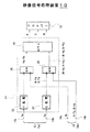
図1はこの発明に係る映像信号処理装置をテレビジョン受像機の映像出力系に適用した場合の一実施形態を示すもので、図4と同一部分には同一の符号を付す。
【0027】
図1において、端子12には従来と同じく主映像信号Saが、他方の端子14には副映像信号Sbがそれぞれ供給される。これら映像信号Sa、Sbとしては図5で説明した信号選択回路40から出力された映像信号を使用することができる。もちろん、映像信号としては特定されるものではないから、図5のような映像信号に制限されるものではない。
【0028】
主映像信号Saに関する第1の輝度信号Yaと色信号Caとは信号処理部20に供給されて鮮鋭度処理や色復調処理などが行われる。
【0029】
主映像信号Saを構成する第1の輝度信号Yaと、副映像信号Sbを構成する第2の輝度信号Ybは、入力輝度信号スイッチング手段である第1のスイッチング手段72に供給されて、輝度信号Ya、Ybの選択が行われる。
【0030】
選択された映像信号Sa若しくはSbは必要に応じて設けられた輝度信号補助処理回路74を介して信号処理部20を構成する輝度信号処理回路22に供給される。輝度信号補助処理回路74は後段の輝度信号処理回路22だけでは鮮鋭度補正が十分でないようなときに使用されるものである。したがってこの輝度信号補助処理回路74は後段の輝度信号処理回路22と同一構成のものを使用することもできれば、特定の処理のみを強調するための処理回路を使用することができる。
【0031】
出力輝度信号スイッチング手段である第2のスイッチング手段26は輝度信号処理回路22より出力された輝度信号と、第2の輝度信号Ybとを選択するためのスイッチング手段であって、副映像として主映像と同様な輝度信号処理をする必要がないときには、この第2のスイッチング手段26で端子14aに供給された第2の輝度信号Ybを直接選択できるようになっている。
【0032】
端子12bに供給された色信号Caは従来と同様に色信号処理回路24に供給されて復調処理やヒュー、カラー調整処理などが施され、その後、出力色差信号スイッチング手段である第3のスイッチング手段28に供給される。第3のスイッチング手段28には以下に示す信号が供給される。
【0033】
端子14bには副映像信号Sbに関する一対の色差信号Ub、Vbが供給され、これら色差信号Ub,Vbは直接入力色差信号スイッチング手段である第4のスイッチング手段78に供給される他、遅延回路76を介してこの第4のスイッチング手段78に供給される。
【0034】
遅延回路76は、第2の輝度信号Ybを輝度信号処理回路74,76を通すことによって発生する伝送時間の遅延を補償するためのもので、同じような遅延時間に設定されている。これによって位相補償された色差信号が得られる。そのため、端子73に供給された切り替え信号によって、第1のスイッチング手段72が破線図示のように切り替えられたときには、端子79から供給される切り替え信号によって第4のスイッチング手段78も破線図示のように切り替えられる。これらの切り替え信号は上述した制御部において生成される。
【0035】
切り替え制御された色差信号Ub、Vbはさらにヒューおよびカラーの調整回路80に供給されて副映像に対するヒュー調整およびカラー調整がそれぞれ行われ、ヒュー調整およびカラー調整された色差信号Ub、Vbは上述した第3のスイッチング手段28に供給されて、主映像に関する色差信号Ua、Vaとの切り替えが行われる。
【0036】
スイッチング手段26,28によって選択された輝度信号Yおよび色差信号U,Vはそれぞれマトリックス回路30に供給されてこの例では原色信号R、G、Bに変換され、変換されたR、G、Bの原色信号がドライバー32を経て表示手段であるCRTの制御電極(グリッド)に供給される。
【0037】
なお、輝度信号処理回路22の出力の一部は速度変調回路(VM)82にも供給され、その出力がドライバー84を介してCRTネック部側に設けられた制御コイル86に供給されて、電子ビームの速度変調が行われる。速度変調することによってコントラストが改善される。
【0038】
このように映像信号の処理装置70を構成した場合、第1と第2のスイッチング手段72,26によって主映像信号Saに関する第1の輝度信号Yaが選択されたときには、輝度信号処理回路22と74とで、輪郭強調処理やダイナミック・ピクチャー処理などの鮮鋭度改善処理が施されるので、鮮明な画質を伴った映像が得られる。
【0039】
これに対して、2分割画面表示のような場合には、PIPプロセッサ60から対応した副映像信号Sbが得られるので、この副映像信号Sbに関する第2の輝度信号Ybが第1のスイッチング手段72によって選択され、分割画面表示用の色差信号Ub,Vbが第3のスイッチング手段28によって選択される。このスイッチング処理によって、2分割画面を構成する輝度信号Yb(P映像とQ映像の双方を映し出すための輝度信号)が輝度信号処理回路22、74に供給される。したがってこれら輝度信号処理回路22,74で、輪郭強調処理やダイナミック・ピクチャー処理などの鮮鋭度改善処理が施されることになるので、互いに同質で鮮明な画質を伴った分割映像が得られる。そのため、分割映像の一方Qが他方Pより画質が低下した状態で映し出されるようなことはない。
【0040】
2分割画面表示用の第2の色差信号Ub、Vbに関しては、ヒューおよびカラー調整回路80が設けられているので、第1の色信号Caと同様にユーザの好みに応じた色相やカラーに調整できる。
【0041】
親子画面表示のような場合には、第1の輝度信号Yaが親画面用の輝度信号となり、第2の輝度信号Ybが子画面用の輝度信号となり、第1の使用態様では、これらが第1のスイッチング手段72で選択されることになるから、この場合にも親画面と子画面の双方の画質を高めることができる。これは、子画面のサイズが親画面の/16,1/9,1/4などのように選択できる場合が多いので、例えば子画面のサイズが1/4程度まで大きくなると、鮮鋭度改善処理を施さないと、親画面との画質の違いが目立ってしまうことがあるからである。
【0042】
もちろん、子画面のサイズが親画面サイズの1/16程度になると、子画面に対して鮮鋭度改善処理を施さないでも、親画面との画質の違いが目立たなくなるので、このような第2の使用態様の場合には第2のスイッチング手段26の方で第1と第2の輝度信号Ya、Ybを切り替えるようにすればよい。
【0043】
第2の色差信号Ub、Vbに関しては、第1の使用態様では遅延回路76が選択され、第2の使用態様ではスルーの状態でヒューおよびカラー調整回路80に供給される。そして、ヒューおよびカラー調整回路80が設けられているので、第1の色信号Caと同様にユーザの好みに応じた色相やカラーに調整できる。そのため、親画面Pに子画面Qの色相やカラーを合わせ込むことができるようになり、色相ずれやカラー違いを簡単に補正できる。
【0044】
上述した信号選択回路40および図1に示す複数のスイッチング手段などは何れも上述した制御部からの信号で適宜制御されるものであるが、この制御部に対するユーザからの指令は、受像機本体のファンクションキーあるいはリモコンキーからのキー操作によって行われるものである。
【0045】
【発明の効果】
以上説明したようにこの発明では第1のスイッチング手段を設けることによって第1の輝度信号と同様に、第2の輝度信号に対しても輝度信号処理を実行できるようにしたものである。
【0046】
これによれば、第1のスイッチング手段によって第2の輝度信号を選択したときには、第1の輝度信号と同様に輝度信号処理回路を通過するので、第1の輝度信号と同じ信号処理が施される。そのため、第1の輝度信号に基づく映像と、第2の輝度信号に基づく映像とがほぼ同じ画質となって映し出される。これで第2の映像を第1の映像と遜色のない映像とすることができる特徴を有する。
【0047】
したがって、この発明はピクチャー・イン・ピクチャー用PIPプロセッサなどを有するテレビジョン受像機の映像処理系にに適用して極めて好適である。
【図面の簡単な説明】
【図1】この発明に係る映像信号処理装置の一実施形態を示す要部の系統図である。
【図2】親子画面表示の例を示す図である。
【図3】2分割画面表示の例を示す図である。
【図4】従来の映像信号処理装置の系統図である。
【図5】信号選択回路の一例を示す系統図である。
【符号の説明】
12、14・・・端子、20・・・信号処理部、22,74・・・輝度信号処理回路、24・・・色信号処理回路、26,28,72,78・・・スイッチング手段、40・・・信号選択回路、76・・・遅延回路、80・・・ヒュー、カラー調整回路[0001]
BACKGROUND OF THE INVENTION
The present invention relates to a video signal processing apparatus suitable for application to a television receiver or the like. Specifically, when video based on a plurality of video signals is displayed on the screen at the same time, the same luminance signal processing system is passed to the sub video signal as in the luminance signal processing system to the main video signal. With such a configuration, the same contour enhancement processing as that of the main video can be performed on the sub video, so that the image quality of the sub video can be improved.
[0002]
[Prior art]
The television receiver can display a plurality of video signals while switching them, or can simultaneously display a plurality of videos based on the plurality of video signals.
[0003]
For example, in the case of the parent-child screen simultaneous display mode as shown in FIG. 2A, the child video Q is displayed at the same time with the parent video P inserted, or the video P and Q are switched as shown in FIG. It can be done. Recently, due to the increased use of landscape display screens, a split display function has been installed that splits the screen into two parts and simultaneously displays two images P and Q on the left and right as shown in FIG. Yes.
[0004]
In this way, when a plurality of videos are displayed simultaneously or switched and displayed, a video signal processing apparatus 10 as shown in FIG. 4 may be used. In the figure, the main video signal Sa is supplied to the
[0005]
The main video signal Sa is a video signal output from a built-in tuner, and includes a luminance signal Ya and a color signal Ca. On the other hand, the sub-picture signal Sb supplied to the
[0006]
In this example, the luminance signal Ya supplied to the
[0007]
The color signal Ca supplied to the
[0008]
Accordingly, the pair of switching means 26 and 28 selects the terminal a when displaying only the video based on the main video signal Sa, and from the above-described control unit during the display mode processing as shown in FIGS. It is controlled by the switching signal. For example, in the case of the parent-child screen display as shown in FIG. 2A, the video based on the main video signal Sa is P, and the video based on the sub-video signal Sb is Q. It can be switched to be selected.
[0009]
The switched luminance signal Y (Ya or Yb) and a pair of color difference signals U and V (Ua, Va, Ub, and Vb) are supplied to the
[0010]
Various signals can be considered as the main video signal Sa and the sub video signal Sb supplied to the
[0011]
In the figure, a video signal for a main screen and a sub screen are provided in a preceding stage of a processing circuit (hereinafter referred to as a PIP processor) 60 that performs picture-in-picture processing (PIP processing) and divided two-screen display processing. A main
[0012]
Both the
[0013]
The separated luminance signal Y and color signal C are supplied to the
[0014]
On the other hand, since the
[0015]
The luminance signal Yb output from the
[0016]
Thus, one
[0017]
Therefore, in the case of the parent / child screen display shown in FIG. 2 or FIG. 3, the luminance signal Ya and the color signal Ca output from the Y /
[0018]
In the case of split screen display as shown in FIG. 3, the split screen display luminance signal Yb and color difference signals Ub and Vb are generated by the
[0019]
The
[0020]
[Problems to be solved by the invention]
By the way, as shown in FIG. 4, since the sub-picture signal Sb is the demodulated color difference signals Ub and Vb supplied to the terminal 14, the switching means 26 provided immediately before the
[0021]
Therefore, for example, when the main video P and the sub video Q are displayed in the same size as in a two-split screen display as shown in FIG. 3, the image quality of the sub video Q is projected in a state of being deteriorated from that of the main video P. Will be. This is because the luminance signal Yb related to the sub-video signal is not subjected to sharpness processing unique to the television receiver, unlike the luminance signal Ya related to the main video signal.
[0022]
Therefore, the present invention solves such a conventional problem, and can perform signal processing similar to the luminance signal related to the main video signal when necessary even for the sub-video signal.
[0023]
[Means for Solving the Problems]
To solve the problems described above, in this invention, the luminance signal processing unit for executing the luminance signal processing a first video signal as a main screen image for the first luminance signal that together constitute the color signals, the color A color signal processing unit that performs demodulation and color signal processing on the signal and outputs a first color difference signal, and a second video signal as a sub-screen video displayed together with the parent screen video is configured with the second color difference signal Output luminance signal switching means for switching between the second luminance signal to be output and the luminance signal output from the luminance signal processing unit, and an output color difference signal for switching between the first color difference signal and the second color difference signal In a video signal processing device having a switching means and a video display device having the video signal processing device, the luminance is switched between the first luminance signal and the second luminance signal. An input luminance signal switching means provided in a preceding stage of the signal processing unit, and a control unit for outputting a switching signal to the output luminance signal switching switching unit, the output color difference signal switching unit, and the input luminance signal switching unit, The input luminance signal switching means is controlled to switch when the small-screen video has a size larger than a predetermined size with respect to the parent screen video, and the output luminance signal switching means has the small-screen video predetermined with respect to the parent screen video Switching is controlled when the size is smaller.
[0024]
In the present invention, when the first switching means is provided and the second luminance signal is selected here, it passes through the luminance signal processing circuit in the same manner as the first luminance signal, so that the same signal processing as the first luminance signal is performed. (Sharpness improvement processing, etc.) is performed. Therefore, the video based on the first luminance signal (main video) and the video based on the second luminance signal (sub-video) are projected with substantially the same image quality. Thus, the second video also becomes an image comparable to the first video.
[0025]
DETAILED DESCRIPTION OF THE INVENTION
Next, an embodiment of a video signal processing apparatus according to the present invention will be described in detail with reference to the drawings.
[0026]
FIG. 1 shows an embodiment in which the video signal processing apparatus according to the present invention is applied to a video output system of a television receiver. The same parts as those in FIG.
[0027]
In FIG. 1, the terminal 12 is supplied with the main video signal Sa as in the conventional case, and the
[0028]
The first luminance signal Ya and the color signal Ca related to the main video signal Sa are supplied to the
[0029]
The first luminance signal Ya constituting the main video signal Sa and the second luminance signal Yb constituting the sub video signal Sb are supplied to the first switching means 72 which is the input luminance signal switching means, and the luminance signal Selection of Ya and Yb is performed.
[0030]
The selected video signal Sa or Sb is supplied to the luminance
[0031]
The second switching means 26, which is an output luminance signal switching means, is a switching means for selecting the luminance signal output from the luminance
[0032]
The color signal Ca supplied to the terminal 12b is supplied to the color
[0033]
A pair of color difference signals Ub and Vb related to the sub-picture signal Sb is supplied to the terminal 14b. These color difference signals Ub and Vb are directly supplied to the fourth switching means 78 which is the input color difference signal switching means, and the
[0034]
The
[0035]
The color-difference signals Ub and Vb subjected to the switching control are further supplied to the hue and
[0036]
The luminance signal Y and the color difference signals U, V selected by the switching means 26, 28 are respectively supplied to the
[0037]
A part of the output of the luminance
[0038]
When the video signal processing device 70 is configured in this way, when the first luminance signal Ya related to the main video signal Sa is selected by the first and second switching means 72 and 26, the luminance
[0039]
On the other hand, in the case of the two-divided screen display, the corresponding sub video signal Sb is obtained from the
[0040]
Since the hue and
[0041]
In the case of the parent / child screen display, the first luminance signal Ya becomes the luminance signal for the parent screen, and the second luminance signal Yb becomes the luminance signal for the child screen. In this case, the image quality of both the main screen and the sub screen can be improved. This is because there are many cases where the size of the child screen can be selected such as / 16, 1/9, 1/4, etc. of the parent screen. For example, when the size of the child screen increases to about 1/4, sharpness improvement processing is performed. This is because the difference in image quality from the main screen may become conspicuous.
[0042]
Of course, when the size of the child screen is about 1/16 of the parent screen size, the difference in image quality from the parent screen becomes inconspicuous without performing sharpness improvement processing on the child screen. In the usage mode, the second switching means 26 may switch the first and second luminance signals Ya and Yb.
[0043]
Regarding the second color difference signals Ub and Vb, the
[0044]
The above-described signal selection circuit 40 and the plurality of switching means shown in FIG. 1 are all appropriately controlled by signals from the above-described control unit. This is performed by a key operation from a function key or a remote control key.
[0045]
【The invention's effect】
As described above, in the present invention, the first switching means is provided so that the luminance signal processing can be executed on the second luminance signal as well as the first luminance signal.
[0046]
According to this, when the second luminance signal is selected by the first switching means, it passes through the luminance signal processing circuit in the same manner as the first luminance signal, so that the same signal processing as the first luminance signal is performed. The Therefore, the video based on the first luminance signal and the video based on the second luminance signal are projected with substantially the same image quality. Thus, the second video is characterized in that it can be an image comparable to the first video.
[0047]
Therefore, the present invention is very suitable when applied to a video processing system of a television receiver having a picture-in-picture PIP processor.
[Brief description of the drawings]
FIG. 1 is a system diagram of a principal part showing an embodiment of a video signal processing apparatus according to the present invention.
FIG. 2 is a diagram illustrating an example of a parent-child screen display.
FIG. 3 is a diagram illustrating an example of a two-divided screen display.
FIG. 4 is a system diagram of a conventional video signal processing apparatus.
FIG. 5 is a system diagram showing an example of a signal selection circuit.
[Explanation of symbols]
12, 14 ... terminals, 20 ... signal processing unit, 22, 74 ... luminance signal processing circuit, 24 ... color signal processing circuit, 26, 28, 72, 78 ... switching means, 40 ... Signal selection circuit, 76 ... Delay circuit, 80 ... Hue, Color adjustment circuit
Claims (4)
上記第1の輝度信号と上記第2の輝度信号を切り替えるため上記輝度信号処理部の前段に設けられる入力輝度信号スイッチング手段と、
上記出力輝度信号切替スイッチング部、上記出力色差信号スイッチング手段および上記入力輝度信号スイッチング手段ヘの切り換え信号を出力する制御部とを備え、
上記入力輝度信号スイッチング手段は、上記親画面映像に対して上記子画面映像が所定以上のサイズのとき切り替え制御され、
上記出力輝度信号スイッチング手段は、上記親画面映像に対して上記子画面映像が所定より小さいサイズのとき切り替え制御される
ことを特徴とする映像信号処理装置。 Luminance signal processing unit for executing the luminance signal processing to the first luminance signal that together constitute the color signal of the first video signal as a main screen image, first performs demodulation and color signal processing on the color signals A color signal processing unit that outputs one color difference signal; a second luminance signal that constitutes a second video signal as a small-screen image displayed together with the parent screen image together with a second color difference signal; and the luminance signal processing unit Video having an output luminance signal switching means for switching and outputting the luminance signal output from the output, and an output color difference signal switching means for switching and outputting the first color difference signal and the second color difference signal In the signal processing device,
Input luminance signal switching means provided in a preceding stage of the luminance signal processing unit for switching between the first luminance signal and the second luminance signal;
A control unit for outputting a switching signal to the output luminance signal switching switching unit, the output color difference signal switching unit, and the input luminance signal switching unit;
The input luminance signal switching means is controlled to be switched when the small-screen video is larger than a predetermined size with respect to the main-screen video,
The video signal processing apparatus, wherein the output luminance signal switching means is controlled to be switched when the small-screen video is smaller than a predetermined size with respect to the main-screen video .
上記入力輝度信号スイッチング手段で上記第2の輝度信号が選択されたとき上記出力色差信号スイッチング手段は、上記遅延部により遅延された第2の色差信号を選択するよう制御される
ことを特徴とする請求項1記載の映像信号処理装置。 A delay unit that delays the second color difference signal for a predetermined time;
When the second luminance signal is selected by the input luminance signal switching means , the output color difference signal switching means is controlled to select the second color difference signal delayed by the delay unit. The video signal processing apparatus according to claim 1.
ことを特徴とする請求項2記載の映像信号処理装置。The video signal processing apparatus according to claim 2 , wherein a color adjustment unit that performs color adjustment is connected to a subsequent stage of the delay unit .
上記マトリックス部からの原色信号に基づき映像を表示する映像表示部と、
上記第1の輝度信号と上記第2の輝度信号を切り替えるため上記輝度信号処理部の前段に設けられる入力輝度信号スイッチング手段と、
上記出力輝度信号スイッチング手段、上記出力色差信号スイッチング手段および上記入力輝度信号スイッチング手段ヘの切り換え信号を出力する制御部とを備え、
上記入力輝度信号スイッチング手段は、上記親画面映像に対して上記子画面映像が所定以上のサイズのとき切り替え制御され、
上記出力輝度信号スイッチング手段は、上記親画面映像に対して上記子画面映像が所定より小さいサイズのとき切り替え制御される
ことを特徴とする映像表示装置。 Luminance signal processing unit for executing the luminance signal processing to the first luminance signal that together constitute the color signal of the first video signal as a main screen image, first performs demodulation and color signal processing on the color signals A color signal processing unit that outputs one color difference signal; a second luminance signal that constitutes a second video signal as a small-screen image displayed together with the parent screen image together with a second color difference signal; and the luminance signal processing unit Output luminance signal switching means for switching and outputting the output luminance signal, output color difference signal switching means for switching and outputting the first color difference signal and the second color difference signal, and the output Video signal comprising a matrix portion for converting the luminance signal selected by the luminance signal switching means and the color difference signal selected by the output color difference signal switching means into a primary color signal And management apparatus,
An image display unit for displaying an image based on the primary color signal from the matrix unit;
Input luminance signal switching means provided in a preceding stage of the luminance signal processing unit for switching between the first luminance signal and the second luminance signal;
A controller that outputs a switching signal to the output luminance signal switching means, the output color difference signal switching means, and the input luminance signal switching means;
The input luminance signal switching means is controlled to be switched when the small-screen video is larger than a predetermined size with respect to the main-screen video,
The output luminance signal switching means is controlled to switch when the sub-screen video is smaller than a predetermined size with respect to the main screen video.
A video display device characterized by that.
Priority Applications (1)
| Application Number | Priority Date | Filing Date | Title |
|---|---|---|---|
| JP21685597A JP3731304B2 (en) | 1997-08-11 | 1997-08-11 | Video signal processing device and video display device |
Applications Claiming Priority (1)
| Application Number | Priority Date | Filing Date | Title |
|---|---|---|---|
| JP21685597A JP3731304B2 (en) | 1997-08-11 | 1997-08-11 | Video signal processing device and video display device |
Publications (2)
| Publication Number | Publication Date |
|---|---|
| JPH1169371A JPH1169371A (en) | 1999-03-09 |
| JP3731304B2 true JP3731304B2 (en) | 2006-01-05 |
Family
ID=16694971
Family Applications (1)
| Application Number | Title | Priority Date | Filing Date |
|---|---|---|---|
| JP21685597A Expired - Fee Related JP3731304B2 (en) | 1997-08-11 | 1997-08-11 | Video signal processing device and video display device |
Country Status (1)
| Country | Link |
|---|---|
| JP (1) | JP3731304B2 (en) |
-
1997
- 1997-08-11 JP JP21685597A patent/JP3731304B2/en not_active Expired - Fee Related
Also Published As
| Publication number | Publication date |
|---|---|
| JPH1169371A (en) | 1999-03-09 |
Similar Documents
| Publication | Publication Date | Title |
|---|---|---|
| JP3326628B2 (en) | Multiplex video television receiver | |
| JP4467479B2 (en) | Video signal processing device | |
| US7982810B2 (en) | Panel-type image display device and liquid crystal television | |
| JP2950503B2 (en) | Multi-system television receiver for PC monitor | |
| JP4708259B2 (en) | Display device and control method thereof | |
| JP2004120757A (en) | Method for processing picture signal and picture processing unit | |
| US7428018B2 (en) | Apparatus and method for adjusting screen | |
| JP2004159081A (en) | Video output apparatus | |
| JPH08163461A (en) | Multi-screen television receiver | |
| JPH0746508A (en) | Main picture position compensation circuit and its method | |
| JPH06205326A (en) | Television receiver | |
| JP3731304B2 (en) | Video signal processing device and video display device | |
| JPH077685A (en) | Television receiver | |
| JPH1079899A (en) | Television image receiver | |
| JP2827214B2 (en) | Television receiver | |
| JPH06133240A (en) | Osd display device | |
| JPH07162779A (en) | Multiscreen display television receiver | |
| JP4055011B2 (en) | Receiver | |
| JPS643431B2 (en) | ||
| JPH04322577A (en) | Television receiver | |
| JP2603673Y2 (en) | Television receiver | |
| JP2507710Y2 (en) | PIP TV receiver | |
| JP2000175116A (en) | Television receiver | |
| JP2002158939A (en) | Television receiver dealing with digital broadcasting | |
| JPH05292510A (en) | Television set |
Legal Events
| Date | Code | Title | Description |
|---|---|---|---|
| A977 | Report on retrieval |
Free format text: JAPANESE INTERMEDIATE CODE: A971007 Effective date: 20050330 |
|
| A131 | Notification of reasons for refusal |
Free format text: JAPANESE INTERMEDIATE CODE: A131 Effective date: 20050412 |
|
| A521 | Written amendment |
Free format text: JAPANESE INTERMEDIATE CODE: A523 Effective date: 20050613 |
|
| TRDD | Decision of grant or rejection written | ||
| A01 | Written decision to grant a patent or to grant a registration (utility model) |
Free format text: JAPANESE INTERMEDIATE CODE: A01 Effective date: 20050920 |
|
| A61 | First payment of annual fees (during grant procedure) |
Free format text: JAPANESE INTERMEDIATE CODE: A61 Effective date: 20051003 |
|
| LAPS | Cancellation because of no payment of annual fees |