JP3726825B2 - Heart rate signal correction method - Google Patents
Heart rate signal correction method Download PDFInfo
- Publication number
- JP3726825B2 JP3726825B2 JP2003178559A JP2003178559A JP3726825B2 JP 3726825 B2 JP3726825 B2 JP 3726825B2 JP 2003178559 A JP2003178559 A JP 2003178559A JP 2003178559 A JP2003178559 A JP 2003178559A JP 3726825 B2 JP3726825 B2 JP 3726825B2
- Authority
- JP
- Japan
- Prior art keywords
- signal
- reference value
- heartbeat signal
- heartbeat
- interval
- Prior art date
- Legal status (The legal status is an assumption and is not a legal conclusion. Google has not performed a legal analysis and makes no representation as to the accuracy of the status listed.)
- Expired - Fee Related
Links
Images


Landscapes
- Measuring Pulse, Heart Rate, Blood Pressure Or Blood Flow (AREA)
Description
【0001】
【発明の属する技術分野】
本発明は測定された心拍信号の基準値を用いて行う心拍信号の補正方法に関するものである。
【0002】
【従来の技術】
心拍信号を測定してこの心拍情報を利用するにあたり、電気的ノイズや被験者の動きなどによって不正確な情報しか得られないケースが多々ある。このために測定された心拍信号にノイズがのっていないかどうかを検査しなくてはならないのであるが、従来は人間の心拍間隔として妥当な上限値と下限値とを用いて、測定された心拍信号の妥当性をチェックしているにとどまっている。
【0003】
また、測定された心拍信号にたとえばノイズがのっていたり欠損していることが明らかであるにもかかわらず、連続した心拍信号が必要である場合、測定された心拍信号からノイズを除去する補正を行ったり、心拍信号の欠損部分を補完する補正を行うことが必要となる。この時の補正のための基準値としては、従来、心拍間隔の平均値を用いている。
【0004】
【発明が解決しようとする課題】
しかし、上記上限値と下限値とを用いた妥当性のチェックだけではノイズの多いシステムにおいては正確な検査が行われているとは言い難い。また心拍信号の補正についても、人間の心拍間隔の条件を満たすタイミングでノイズが偶然混入している時には、これに対処することができない。加えるに、基準値の作成に際して不正確な情報が混入している可能性も存在しており、このような基準値に基づいた補正では、補正された後の心拍信号も不正確なものとなってしまう。
【0005】
本発明はこのような点に鑑みなされたものであり、その目的とするところは心拍信号検査用基準値として適切な値で導出した基準値を用いて心拍信号の補正を適切に行うことができる心拍信号補正方法を提供するにある。
【0006】
【課題を解決するための手段】
しかして本発明は、間隔のばらつきが所定%以内である心拍信号が所定回数以上連続して測定された時の心拍信号間隔の平均値を心拍信号検査用の基準値とすることに特徴を有している。連続した心拍間隔のばらつきに注目して、ばらつきが所定の範囲に収まっていなければ人間の心拍間隔として妥当な範囲であってもキャンセルして、基準値に反映されないようにするのである。
【0007】
そして本発明に係る心拍信号補正方法は、測定された心拍信号のうち、この基準値の所定%以下の間隔の信号はキャンセルすることに第1の特徴を有し、測定された心拍信号のうち、上記導出方法で得られた基準値の所定%以上の間隔の信号についてはその間に補完のための信号を挿入することに第2の特徴を有している。
【0008】
上記両補正方法を共に行うことが好ましいのはもちろんであり、この場合、基準値の所定%以下の間隔の信号のキャンセルを行い、次いで基準値の所定%以上の間隔の信号についてはその間に補完のための信号を挿入するものとする。
【0009】
信号の挿入に際しては、信号を挿入することによってできるそれぞれの間隔が基準値に最も近くなるような本数及び位置に配置することが好ましい。
【0010】
【発明の実施の形態】
以下本発明について詳述すると、図2は基準値の導出方法及び心拍信号補正方法を実装するためのシステム構成の一例を示している。被験者1からピックアップ2によって検出された心拍による物理的な変化は検出回路3によって電気信号に変換されて二値化回路4によってデジタル信号に変換された後、マイクロコンピュータ(CPU)5に入力される。上記導出方法及び補正方法はCPU5に適した方法で実装され、具体的な作業はCPU5内で行われる。以下このシステムを想定して導出方法及び補正方法について説明する。なお上記システムでは信号の立ち上がりエッジを心拍と認識するようなシステム及び制御プログラムの構成になっているとする。
【0011】
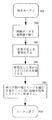
まず基準値の導出についてであるが、これは図1に示すように、ステップ202で検出されたデータをステップ203にて間隔データとする。次いでステップ204において間隔データの妥当性について検査する。これは人間の心拍間隔として正常であるかということについて調べるものであり、従来例でも述べたように、人間の心拍間隔の上限値(H-limit msec)と下限値(L-limit msec)との間に収まっているかどうかをチェックする。なお、この両値については、システムの用途やシステムの対象者の状態などによって多少変化すると考えられる。
【0012】
ステップ204において異常と判断されれば検出の累積数をキャンセルして次の間隔データを待つ。正常であればステップ206において間隔のばらつきが±R%以内であるかどうかを検査する。同一の人物が同一の状態である場合、心拍間隔のばらつきの範囲は、ステップ204で検査した正常範囲よりもはるかに狭くなくてはならず、ばらつきの大きい連続した信号についてはノイズであると判断することができる。ここでの閾値Rについても対象者やシステムに依存するため一概に決めることはできないが、20〜30%の値を好適に使用することができる。
【0013】
そしてステップ206において異常と判断された時には、上記ステップ204の場合と同様に処理され、正常であればデータの検出数に1を加える(ステップ207)。以上の処理を繰り返すことによって、連続するX個の正常な間隔データが検出されたならば、それらの平均値を求めて基準値とする。このときのXについては、少なすぎると値の信頼性が低くなり、多すぎると基準値を得るのに時間がかかりすぎてしまうことから、3〜10ぐらい、好ましくは5程度が適当である。
【0014】
次に測定された心拍信号を上記基準値を用いて補正する補正方法について説明する。まず本来の心拍信号の間にノイズが入った場合のような誤報については、図3に示すように、測定した心拍信号の間隔データが基準値のA%より小さい場合には異常と判定して、今回得られた立ち上がりエッジをキャンセルして検出されなかったものとする。また前回の立ち上がりエッジに関しても間隔データとして正常であると判定はされているが、微妙な前後へのシフトの可能性があるのでキャンセルし前々回の立ち上がりエッジを信頼できる最後のエッジと設定し次の処理を行う。
【0015】
次に本来の心拍信号が欠損している場合のような失報については、図4に示すように、測定した心拍信号の間隔データが基準値のB%より大きい場合、今回と前回の立ち上がりのエッジの間に検出されるべき信号が検出されなかったとして、次に述べる信号の補完を行う。
【0016】
図5に補完ルーチンを示す。ステップ502において、その間に複数の検出されてない信号を含むと考えられる間隔データを基準値で除す。得られた答についてはステップ503及びステップ504において四捨五入などの適切な方法で整数化したのち1を引く。こうして得られた値を補完すべき信号の数とし、その本数の補完エッジ(心拍信号)を間隔データ内に配置するのであるが、この配置にあたってはこれらが等間隔となるようにする。
【0017】
上記補正にあたっての閾値A,Bの値としては、A=80%〜60%、B=125%〜150%の値を好適に用いることができるが、これらの値にしても、この補正方法が実装されるシステムに依存するので一概に決めることはできない。例えばだんだん心拍間隔が広くなることが予測されるシステム(例えば眠りを誘うようなシステム)においてはBの値を大きめに、Aの値を小さめに設定するべきであり、またこのようにシステムの特性を加味することによってより精度の高い補正を行うことができる。
【0018】
上記誤報と失報とに対する補正は、組み合わせて実行することが好ましいのはもちろんであり、この場合のフローを図6に示す。誤報に対する補正の後に、失報に対する補正を行う。基準値と比較して短すぎる間隔データをキャンセルして間隔の広すぎる間隔データとして扱って補完を行うということができて、アルゴリズムの単純化及び高速化を期待することができる。
【0019】
以上のシステムは説明の一例としてリアルタイム処理系を示したが、それに限定するものではなくバッチ処理系にも応用することができる。
【0020】
【発明の効果】
以上のように心拍信号検査用基準値の導出は、ばらつき範囲を設定しているために、短時間でより正確な基準値を導出することができる。そして本発明の心拍信号補正方法においては、基準値の所定%以下の間隔の信号はキャンセルし、基準値の所定%以上の間隔の信号についてはその間に基準値から導いた補完のための信号を挿入するにあたり、正確な基準値を用いるために、より正確な補正を行うことができるものである。特に基準値と比較して短すぎる間隔データは修正するのではなくキャンセルして間隔の広すぎる間隔データとして扱って補完を行うことにより、アルゴリズムの単純化及び高速化を期待することができる。
【0021】
また、信号の挿入による補完に際し、信号を挿入することによってできるそれぞれの間隔が基準値に最も近くなるような本数及び位置に配置することで、実際の心拍信号により近い信号の補完を行うことができる。
【図面の簡単な説明】
【図1】本発明における基準値導出に関するフローチャートである。
【図2】同上のシステム構成図である。
【図3】誤報に対する補正に関するフローチャートである。
【図4】失報に対する補正に関するフローチャートである。
【図5】補完補正についてのフローチャートである。
【図6】補正に関するフローチャートである。
【符号の説明】
1 被験者
2 ピックアップ
3 検出回路
4 二値化回路
5 CPU[0001]
BACKGROUND OF THE INVENTION
The present invention relates to a heartbeat signal correction method performed using a measured reference value of a heartbeat signal.
[0002]
[Prior art]
In measuring the heartbeat signal and using this heartbeat information, there are many cases where only inaccurate information can be obtained due to electrical noise, subject movement, and the like. For this reason, it is necessary to check whether the measured heartbeat signal is free of noise, but in the past, it was measured using the upper and lower limits that are reasonable for human heartbeat intervals. It only checks the validity of the heart rate signal.
[0003]
Also, a correction that removes noise from the measured heartbeat signal when a continuous heartbeat signal is required, even though it is clear that the measured heartbeat signal has, for example, noise. It is necessary to perform correction to compensate for the missing portion of the heartbeat signal. Conventionally, an average value of heartbeat intervals is used as a reference value for correction at this time.
[0004]
[Problems to be solved by the invention]
However, it is difficult to say that an accurate inspection is performed in a noisy system only by checking validity using the upper limit value and the lower limit value. Further, the correction of the heartbeat signal cannot be dealt with when noise is accidentally mixed in at the timing satisfying the condition of the human heartbeat interval. In addition, there is a possibility that inaccurate information is mixed in the creation of the reference value, and in the correction based on such a reference value, the corrected heart rate signal is also inaccurate. End up.
[0005]
The present invention has been made in view of the above points, and an object of the present invention is to appropriately correct a heartbeat signal using a reference value derived as an appropriate value as a reference value for heartbeat signal inspection. It is to provide a heartbeat signal correction method.
[0006]
[Means for Solving the Problems]
Therefore, the present invention is characterized in that an average value of heartbeat signal intervals when a heartbeat signal having a variation in interval within a predetermined percentage is continuously measured a predetermined number of times or more is used as a reference value for heartbeat signal inspection. are doing. Focusing on the variation in the continuous heartbeat interval, if the variation is not within a predetermined range, even if it is within a reasonable range for the human heartbeat interval, it is canceled and not reflected in the reference value.
[0007]
The heartbeat signal correction method according to the present invention has a first feature in canceling a signal having an interval equal to or less than a predetermined percentage of the reference value among the measured heartbeat signals. A second feature resides in that a signal for complementation is inserted between signals having intervals of a predetermined percentage or more of the reference value obtained by the derivation method.
[0008]
Of course, it is preferable to perform both of the above correction methods. In this case, signals having an interval equal to or less than a predetermined percentage of the reference value are canceled, and then signals having an interval equal to or greater than the predetermined value of the reference value are complemented in the meantime. It is assumed that a signal for is inserted.
[0009]
When inserting the signals, it is preferable to arrange them in such numbers and positions that the intervals generated by inserting the signals are closest to the reference value.
[0010]
DETAILED DESCRIPTION OF THE INVENTION
Hereinafter, the present invention will be described in detail. FIG. 2 shows an example of a system configuration for implementing a reference value deriving method and a heartbeat signal correcting method. A physical change caused by a heartbeat detected from the subject 1 by the
[0011]
First, regarding the derivation of the reference value, as shown in FIG. 1, the data detected in
[0012]
If it is determined as abnormal in step 204, the accumulated number of detections is canceled and the next interval data is awaited. If normal, it is checked in
[0013]
If it is determined in
[0014]
Next, a correction method for correcting the measured heartbeat signal using the reference value will be described. First, as shown in FIG. 3, regarding false alarms such as when noise enters between the original heartbeat signals, it is determined that there is an abnormality when the measured heartbeat signal interval data is smaller than A% of the reference value. It is assumed that the rising edge obtained this time is canceled and not detected. Also, although it is determined that the previous rising edge is normal as the interval data, there is a possibility of a slight forward / backward shift, so cancel the previous rising edge and set the last rising edge as the reliable last edge. Process.
[0015]
Next, as shown in FIG. 4, when the original heartbeat signal is missing, if the measured heartbeat signal interval data is greater than B% of the reference value, as shown in FIG. Assuming that a signal to be detected during the edge is not detected, the following signal complement is performed.
[0016]
FIG. 5 shows a complement routine. In
[0017]
As the values of the thresholds A and B in the correction, values of A = 80% to 60% and B = 125% to 150% can be preferably used. Since it depends on the system to be implemented, it cannot be decided unconditionally. For example, in a system in which the heartbeat interval is predicted to gradually increase (for example, a system that induces sleep), the value of B should be set larger and the value of A should be set smaller. By taking into account, correction with higher accuracy can be performed.
[0018]
Needless to say, the correction for the false alarm and the misreport is preferably performed in combination, and the flow in this case is shown in FIG. After correction for false alarms, correction for false alarms is performed. It is possible to cancel the interval data that is too short compared to the reference value, treat it as interval data that is too wide, and perform complementation, so that simplification and speeding up of the algorithm can be expected.
[0019]
The above system shows a real-time processing system as an example of the description, but the present invention is not limited to this and can be applied to a batch processing system.
[0020]
【The invention's effect】
As described above, since the derivation of the reference value for heartbeat signal inspection sets a variation range, a more accurate reference value can be derived in a short time. In the heartbeat signal correction method of the present invention, signals having an interval equal to or less than a predetermined percentage of the reference value are canceled, and signals having an interval equal to or greater than the predetermined percentage of the reference value are interpolated with signals for complementation derived from the reference value. In insertion, more accurate correction can be performed in order to use an accurate reference value. In particular, interval data that is too short compared to the reference value is not corrected, but is canceled and treated as interval data that is too wide.
[0021]
In addition, when complementing by inserting signals, signals that are closer to the actual heartbeat signal can be complemented by arranging them at the number and position where each interval that can be obtained by inserting the signal is closest to the reference value. it can.
[Brief description of the drawings]
FIG. 1 is a flowchart regarding reference value derivation in the present invention.
FIG. 2 is a system configuration diagram of the above.
FIG. 3 is a flowchart regarding correction for false alarms.
FIG. 4 is a flowchart relating to correction for missing information.
FIG. 5 is a flowchart for complementary correction.
FIG. 6 is a flowchart regarding correction.
[Explanation of symbols]
1
Claims (4)
Priority Applications (1)
| Application Number | Priority Date | Filing Date | Title |
|---|---|---|---|
| JP2003178559A JP3726825B2 (en) | 2003-06-23 | 2003-06-23 | Heart rate signal correction method |
Applications Claiming Priority (1)
| Application Number | Priority Date | Filing Date | Title |
|---|---|---|---|
| JP2003178559A JP3726825B2 (en) | 2003-06-23 | 2003-06-23 | Heart rate signal correction method |
Related Parent Applications (1)
| Application Number | Title | Priority Date | Filing Date |
|---|---|---|---|
| JP33724695A Division JP3460419B2 (en) | 1995-12-25 | 1995-12-25 | Derivation of reference value for heart rate signal test |
Publications (2)
| Publication Number | Publication Date |
|---|---|
| JP2004000660A JP2004000660A (en) | 2004-01-08 |
| JP3726825B2 true JP3726825B2 (en) | 2005-12-14 |
Family
ID=30438370
Family Applications (1)
| Application Number | Title | Priority Date | Filing Date |
|---|---|---|---|
| JP2003178559A Expired - Fee Related JP3726825B2 (en) | 2003-06-23 | 2003-06-23 | Heart rate signal correction method |
Country Status (1)
| Country | Link |
|---|---|
| JP (1) | JP3726825B2 (en) |
Families Citing this family (4)
| Publication number | Priority date | Publication date | Assignee | Title |
|---|---|---|---|---|
| JP5315948B2 (en) * | 2008-11-19 | 2013-10-16 | 富士通株式会社 | Pulse rate calculation program, pulse rate calculation device, pulse rate calculation method, and portable terminal device |
| BRPI1015314A2 (en) | 2009-04-26 | 2016-04-19 | Nike International Ltd | device for monitoring a user's athletic performance |
| US9141087B2 (en) | 2009-04-26 | 2015-09-22 | Nike, Inc. | Athletic watch |
| KR101817587B1 (en) * | 2012-01-04 | 2018-01-11 | 나이키 이노베이트 씨.브이. | Athletic watch |
-
2003
- 2003-06-23 JP JP2003178559A patent/JP3726825B2/en not_active Expired - Fee Related
Also Published As
| Publication number | Publication date |
|---|---|
| JP2004000660A (en) | 2004-01-08 |
Similar Documents
| Publication | Publication Date | Title |
|---|---|---|
| US8897864B2 (en) | Heart rate meter and method for removing noise of heart beat waveform | |
| EP3576093A1 (en) | Method and system for clinical effectiveness evaluation of artificial intelligence based medical device | |
| RU2012101554A (en) | ECG CONTROL WITH REDUCED FALSE ALARMS IN CONNECTION WITH ASYSTOLIA | |
| CN114491383B (en) | Abnormal data processing method and system for bridge monitoring | |
| JP5562805B2 (en) | Pulse rate measuring method and blood oxygen saturation measuring method | |
| JP3729143B2 (en) | Pulse wave measuring device | |
| CN108324271A (en) | Electrocardiosignal recognition methods, system and cardioelectric monitor equipment | |
| JP3726825B2 (en) | Heart rate signal correction method | |
| JP2001198094A (en) | Pulse rate detector | |
| JP4040096B2 (en) | Device for detecting electromagnetic interference | |
| US8005882B2 (en) | System and method for determining application of adaptive filter | |
| JP3460419B2 (en) | Derivation of reference value for heart rate signal test | |
| KR102461702B1 (en) | Processing method for electrocardiogram signal | |
| JP2002214185A (en) | Detecting method and detecting device for sensor abnormality | |
| EP2938247B1 (en) | Method and apparatus for reducing motion artifacts in ecg signals | |
| CN110403593B (en) | Heart rate detection method | |
| JPH06154342A (en) | Pace maker pulse detecting circuit | |
| CN110960203A (en) | Cardiovascular characteristic parameter detection method and device | |
| WO2024018697A1 (en) | Heart rate detection system, heart rate detection method, and program | |
| WO2023032120A1 (en) | Heartbeat detection method and heartbeat detection device | |
| CN117213532B (en) | Multifunctional microfluidic flexible sensor | |
| JP7160460B2 (en) | Pulse rate calculation method, pulse rate calculation device, recording medium | |
| JPH0444988B2 (en) | ||
| CN117426755A (en) | Sleep monitoring method and device and intelligent equipment | |
| JP3861848B2 (en) | Abnormal sound inspection method |
Legal Events
| Date | Code | Title | Description |
|---|---|---|---|
| TRDD | Decision of grant or rejection written | ||
| A01 | Written decision to grant a patent or to grant a registration (utility model) |
Free format text: JAPANESE INTERMEDIATE CODE: A01 Effective date: 20050906 |
|
| A61 | First payment of annual fees (during grant procedure) |
Free format text: JAPANESE INTERMEDIATE CODE: A61 Effective date: 20050919 |
|
| FPAY | Renewal fee payment (event date is renewal date of database) |
Free format text: PAYMENT UNTIL: 20081007 Year of fee payment: 3 |
|
| FPAY | Renewal fee payment (event date is renewal date of database) |
Free format text: PAYMENT UNTIL: 20091007 Year of fee payment: 4 |
|
| FPAY | Renewal fee payment (event date is renewal date of database) |
Free format text: PAYMENT UNTIL: 20091007 Year of fee payment: 4 |
|
| S533 | Written request for registration of change of name |
Free format text: JAPANESE INTERMEDIATE CODE: R313533 |
|
| FPAY | Renewal fee payment (event date is renewal date of database) |
Free format text: PAYMENT UNTIL: 20091007 Year of fee payment: 4 |
|
| R350 | Written notification of registration of transfer |
Free format text: JAPANESE INTERMEDIATE CODE: R350 |
|
| FPAY | Renewal fee payment (event date is renewal date of database) |
Free format text: PAYMENT UNTIL: 20101007 Year of fee payment: 5 |
|
| FPAY | Renewal fee payment (event date is renewal date of database) |
Free format text: PAYMENT UNTIL: 20101007 Year of fee payment: 5 |
|
| FPAY | Renewal fee payment (event date is renewal date of database) |
Free format text: PAYMENT UNTIL: 20111007 Year of fee payment: 6 |
|
| FPAY | Renewal fee payment (event date is renewal date of database) |
Free format text: PAYMENT UNTIL: 20111007 Year of fee payment: 6 |
|
| FPAY | Renewal fee payment (event date is renewal date of database) |
Free format text: PAYMENT UNTIL: 20121007 Year of fee payment: 7 |
|
| FPAY | Renewal fee payment (event date is renewal date of database) |
Free format text: PAYMENT UNTIL: 20131007 Year of fee payment: 8 |
|
| LAPS | Cancellation because of no payment of annual fees |