JP3719602B2 - Video tape recorder and recording method - Google Patents
Video tape recorder and recording method Download PDFInfo
- Publication number
- JP3719602B2 JP3719602B2 JP2002166496A JP2002166496A JP3719602B2 JP 3719602 B2 JP3719602 B2 JP 3719602B2 JP 2002166496 A JP2002166496 A JP 2002166496A JP 2002166496 A JP2002166496 A JP 2002166496A JP 3719602 B2 JP3719602 B2 JP 3719602B2
- Authority
- JP
- Japan
- Prior art keywords
- data
- video
- video data
- auxiliary
- sector
- Prior art date
- Legal status (The legal status is an assumption and is not a legal conclusion. Google has not performed a legal analysis and makes no representation as to the accuracy of the status listed.)
- Expired - Fee Related
Links
- 238000000034 method Methods 0.000 title claims description 32
- 238000007726 management method Methods 0.000 claims description 60
- 238000013144 data compression Methods 0.000 claims description 17
- 230000000903 blocking effect Effects 0.000 claims 2
- 238000012545 processing Methods 0.000 description 43
- 238000012937 correction Methods 0.000 description 24
- 238000001514 detection method Methods 0.000 description 19
- 238000006243 chemical reaction Methods 0.000 description 18
- 238000000926 separation method Methods 0.000 description 13
- 230000015654 memory Effects 0.000 description 11
- 238000010586 diagram Methods 0.000 description 9
- 230000006837 decompression Effects 0.000 description 6
- 230000003139 buffering effect Effects 0.000 description 3
- 238000003780 insertion Methods 0.000 description 3
- 230000037431 insertion Effects 0.000 description 3
- 230000000694 effects Effects 0.000 description 2
- 238000012856 packing Methods 0.000 description 2
- 230000003111 delayed effect Effects 0.000 description 1
- 238000005070 sampling Methods 0.000 description 1
- 238000004804 winding Methods 0.000 description 1
Images


Classifications
-
- G—PHYSICS
- G11—INFORMATION STORAGE
- G11B—INFORMATION STORAGE BASED ON RELATIVE MOVEMENT BETWEEN RECORD CARRIER AND TRANSDUCER
- G11B20/00—Signal processing not specific to the method of recording or reproducing; Circuits therefor
- G11B20/10—Digital recording or reproducing
- G11B20/12—Formatting, e.g. arrangement of data block or words on the record carriers
- G11B20/1201—Formatting, e.g. arrangement of data block or words on the record carriers on tapes
- G11B20/1207—Formatting, e.g. arrangement of data block or words on the record carriers on tapes with transverse tracks only
- G11B20/1208—Formatting, e.g. arrangement of data block or words on the record carriers on tapes with transverse tracks only for continuous data, e.g. digitised analog information signals, pulse code modulated [PCM] data
-
- G—PHYSICS
- G11—INFORMATION STORAGE
- G11B—INFORMATION STORAGE BASED ON RELATIVE MOVEMENT BETWEEN RECORD CARRIER AND TRANSDUCER
- G11B27/00—Editing; Indexing; Addressing; Timing or synchronising; Monitoring; Measuring tape travel
- G11B27/10—Indexing; Addressing; Timing or synchronising; Measuring tape travel
- G11B27/102—Programmed access in sequence to addressed parts of tracks of operating record carriers
- G11B27/107—Programmed access in sequence to addressed parts of tracks of operating record carriers of operating tapes
-
- G—PHYSICS
- G11—INFORMATION STORAGE
- G11B—INFORMATION STORAGE BASED ON RELATIVE MOVEMENT BETWEEN RECORD CARRIER AND TRANSDUCER
- G11B27/00—Editing; Indexing; Addressing; Timing or synchronising; Monitoring; Measuring tape travel
- G11B27/10—Indexing; Addressing; Timing or synchronising; Measuring tape travel
- G11B27/19—Indexing; Addressing; Timing or synchronising; Measuring tape travel by using information detectable on the record carrier
- G11B27/28—Indexing; Addressing; Timing or synchronising; Measuring tape travel by using information detectable on the record carrier by using information signals recorded by the same method as the main recording
- G11B27/30—Indexing; Addressing; Timing or synchronising; Measuring tape travel by using information detectable on the record carrier by using information signals recorded by the same method as the main recording on the same track as the main recording
- G11B27/3027—Indexing; Addressing; Timing or synchronising; Measuring tape travel by using information detectable on the record carrier by using information signals recorded by the same method as the main recording on the same track as the main recording used signal is digitally coded
- G11B27/3063—Subcodes
-
- H—ELECTRICITY
- H04—ELECTRIC COMMUNICATION TECHNIQUE
- H04N—PICTORIAL COMMUNICATION, e.g. TELEVISION
- H04N5/00—Details of television systems
- H04N5/76—Television signal recording
- H04N5/78—Television signal recording using magnetic recording
- H04N5/782—Television signal recording using magnetic recording on tape
- H04N5/7824—Television signal recording using magnetic recording on tape with rotating magnetic heads
- H04N5/7826—Television signal recording using magnetic recording on tape with rotating magnetic heads involving helical scanning of the magnetic tape
- H04N5/78263—Television signal recording using magnetic recording on tape with rotating magnetic heads involving helical scanning of the magnetic tape for recording on tracks inclined relative to the direction of movement of the tape
-
- G—PHYSICS
- G11—INFORMATION STORAGE
- G11B—INFORMATION STORAGE BASED ON RELATIVE MOVEMENT BETWEEN RECORD CARRIER AND TRANSDUCER
- G11B2220/00—Record carriers by type
- G11B2220/90—Tape-like record carriers
-
- H—ELECTRICITY
- H04—ELECTRIC COMMUNICATION TECHNIQUE
- H04N—PICTORIAL COMMUNICATION, e.g. TELEVISION
- H04N5/00—Details of television systems
- H04N5/76—Television signal recording
- H04N5/78—Television signal recording using magnetic recording
- H04N5/782—Television signal recording using magnetic recording on tape
- H04N5/783—Adaptations for reproducing at a rate different from the recording rate
-
- H—ELECTRICITY
- H04—ELECTRIC COMMUNICATION TECHNIQUE
- H04N—PICTORIAL COMMUNICATION, e.g. TELEVISION
- H04N9/00—Details of colour television systems
- H04N9/79—Processing of colour television signals in connection with recording
- H04N9/80—Transformation of the television signal for recording, e.g. modulation, frequency changing; Inverse transformation for playback
- H04N9/804—Transformation of the television signal for recording, e.g. modulation, frequency changing; Inverse transformation for playback involving pulse code modulation of the colour picture signal components
- H04N9/8042—Transformation of the television signal for recording, e.g. modulation, frequency changing; Inverse transformation for playback involving pulse code modulation of the colour picture signal components involving data reduction
-
- H—ELECTRICITY
- H04—ELECTRIC COMMUNICATION TECHNIQUE
- H04N—PICTORIAL COMMUNICATION, e.g. TELEVISION
- H04N9/00—Details of colour television systems
- H04N9/79—Processing of colour television signals in connection with recording
- H04N9/80—Transformation of the television signal for recording, e.g. modulation, frequency changing; Inverse transformation for playback
- H04N9/804—Transformation of the television signal for recording, e.g. modulation, frequency changing; Inverse transformation for playback involving pulse code modulation of the colour picture signal components
- H04N9/806—Transformation of the television signal for recording, e.g. modulation, frequency changing; Inverse transformation for playback involving pulse code modulation of the colour picture signal components with processing of the sound signal
- H04N9/8063—Transformation of the television signal for recording, e.g. modulation, frequency changing; Inverse transformation for playback involving pulse code modulation of the colour picture signal components with processing of the sound signal using time division multiplex of the PCM audio and PCM video signals
-
- H—ELECTRICITY
- H04—ELECTRIC COMMUNICATION TECHNIQUE
- H04N—PICTORIAL COMMUNICATION, e.g. TELEVISION
- H04N9/00—Details of colour television systems
- H04N9/79—Processing of colour television signals in connection with recording
- H04N9/80—Transformation of the television signal for recording, e.g. modulation, frequency changing; Inverse transformation for playback
- H04N9/82—Transformation of the television signal for recording, e.g. modulation, frequency changing; Inverse transformation for playback the individual colour picture signal components being recorded simultaneously only
- H04N9/8205—Transformation of the television signal for recording, e.g. modulation, frequency changing; Inverse transformation for playback the individual colour picture signal components being recorded simultaneously only involving the multiplexing of an additional signal and the colour video signal
- H04N9/8227—Transformation of the television signal for recording, e.g. modulation, frequency changing; Inverse transformation for playback the individual colour picture signal components being recorded simultaneously only involving the multiplexing of an additional signal and the colour video signal the additional signal being at least another television signal
Landscapes
- Engineering & Computer Science (AREA)
- Signal Processing (AREA)
- Multimedia (AREA)
- Signal Processing For Digital Recording And Reproducing (AREA)
- Television Signal Processing For Recording (AREA)
Description
【0001】
【発明の属する技術分野】
本発明は、ビデオテープレコーダ及び記録方法に関し、特にHDTV(High Definition TeleVision)によるビデオ信号を磁気テープに記録するビデオテープレコーダに適用することができる。本発明は、少なくとも再生基準の管理情報を、メインセクタでは再生出力するビデオデータのピクチャー順に、サブコードセクタでは、データ圧縮したビデオデータのピクチャーの順序で記録することにより、全体を効率良く構成することができるようにする。
【0002】
【従来の技術】
従来、例えば特開2001−291335号公報等においては、HDTVのビデオ信号(以下、HD信号と呼ぶ)を記録再生するビデオテープレコーダが提案されるようになされている。
【0003】
この特開2001−291335号公報においては、Pピクチャーの配置周期を単位にして、HD信号に関連する各種の信号を、インターリーブする複数トラックの先頭領域にまとめて記録することにより、磁気テープを有効に利用してHD信号を記録するようにしたビデオテープレコーダが開示されるようになされている。
【0004】
【発明が解決しようとする課題】
しかしながらこの種のHD信号を記録するビデオテープレコーダにおいては、実用化のために、さらに一段と種々の工夫が必要であると考えられる。具体的には、記録再生系を一段と効率良く構成することができれば、その分、全体構成を簡略化し、さらには種々の処理を簡略化することができると考えられる。
【0005】
本発明は以上の点を考慮してなされたもので、全体を効率良く構成することができるビデオテープレコーダ及び記録方法を提案しようとするものである。
【0006】
【課題を解決するための手段】
かかる課題を解決するため請求項1の発明においては、ビデオテープレコーダに適用して、圧縮ビデオデータを所定のピクチャー数単位でブロック化し、該ブロックの圧縮ビデオデータと、対応する圧縮オーディオデータと、対応する補助データとの組み合わせによるパックユニットを生成するパックユニット生成手段と、パックユニットによるデータをメインセクタに割り当て、パックユニットの補助データをサブコードセクタに割り当て、メインセクタ及びサブコードセクタによる記録トラックを順次形成する記録系とを備え、メインセクタの補助データは、少なくともデコード時におけるビデオデータの時刻管理情報に対応する再生基準の管理情報をビデオデータのピクチャーの順序により配置し、サブコードセクタの補助データは、少なくとも再生基準の管理情報、ピクチャータイプの情報を圧縮ビデオデータのピクチャーの順序により配置する。
【0007】
また請求項3の発明においては、記録方法に適用して、圧縮ビデオデータを所定のピクチャー数単位でブロック化し、該ブロックの圧縮ビデオデータと、対応する圧縮オーディオデータと、対応する補助データとの組み合わせによるパックユニットを生成するパックユニット生成ステップと、パックユニットによるデータをメインセクタに割り当て、パックユニットの補助データをサブコードセクタに割り当て、メインセクタ及びサブコードセクタによる記録トラックを順次形成する記録ステップとを備え、メインセクタの補助データは、少なくともデコード時におけるビデオデータの時刻管理情報に対応する再生基準の管理情報をビデオデータのピクチャーの順序により配置し、サブコードセクタの補助データは、少なくとも再生基準の管理情報、ピクチャータイプの情報を圧縮ビデオデータのピクチャーの順序により配置する。
【0008】
請求項1の構成によれば、ビデオテープレコーダに適用して、圧縮ビデオデータを所定のピクチャー数単位でブロック化し、該ブロックの圧縮ビデオデータと、対応する圧縮オーディオデータと、対応する補助データとの組み合わせによるパックユニットを生成するパックユニット生成手段と、パックユニットによるデータをメインセクタに割り当て、パックユニットの補助データをサブコードセクタに割り当て、メインセクタ及びサブコードセクタによる記録トラックを順次形成する記録系とを備えることにより、パックユニット単位で、ビデオデータ、対応するオーディオデータ、対応する補助データを処理することができる。このときメインセクタの補助データは、少なくともデコード時におけるビデオデータの時刻管理情報に対応する再生基準の管理情報をビデオデータのピクチャーの順序により配置し、サブコードセクタの補助データは、少なくとも再生基準の管理情報、ピクチャータイプの情報を圧縮ビデオデータのピクチャーの順序により配置することにより、再生時においては、単に再生された対応する補助データに従って各ピクチャーを処理することにより、ビデオデータを再生し、デコードすることができ、その分、再生側の処理、構成を簡略化することができ、これにより全体を効率良く構成することができる。
【0009】
これにより請求項3の構成によれば、全体を効率良く構成することができる記録方法を提供することができる。
【0010】
【発明の実施の形態】
以下、適宜図面を参照しながら本発明の実施の形態を詳述する。
【0011】
(1)第1の実施の形態の構成
(1−1)記録フォーマット
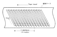
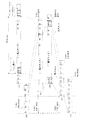
図1は、本発明の実施の形態に係るビデオテープレコーダによる磁気テープ上の記録フォーマットを示す平面図である。このビデオテープレコーダにおいては、DV(Digital Video )方式によるビデオテープレコーダとほぼ同一の磁気テープ走行系を使用するようになされ、これによりDV方式によるビデオテープレコーダをほぼ同一のトラックパターンにより、正及び負のアジマス角による1対の斜めトラック(トラックペアである)が順次磁気テープに形成される。なお図中において、Headは、磁気ヘッドの走査方向を示し、Tape travelは、磁気テープの走行方向である。記録トラックは、約300トラック/1秒の速度により順次作成され、磁気テープに対する記録レートは、約40〔Mbps〕に設定されるようになされている。
【0012】
磁気テープは、順次循環的に、何らパイロット信号を記録していない記録トラック、周波数F0のパイロット信号を記録した記録トラック、周波数F1のパイロット信号を記録した記録トラックが形成される。これにより磁気テープは、このパイロット信号を基準にしてトラッキング制御できるようになされている。なお周波数F0及びF1は、各記録トラックに記録するデータのチャンネルビットの記録周波数に対して、記録周波数が1/90及び1/60となるように設定される。
【0013】
このビデオテープレコーダでは、このようにして形成したトラック列において、16トラックがインターリーブの処理単位、誤り訂正処理の単位(ECCブロック)に設定され、これにより16トラックに記録するデータを順次1つのブロックにまとめ、各ブロック内でそれぞれインターリーブ、誤り訂正の処理が実行されるようになされている。またこの記録トラックは、各トラックペアに値0〜31のトラックペア番号が順次循環的に割り当てられ、インターリーブの先頭トラックペアにおいては、このトラックペア番号が値0、7、15又は値23に設定されるようになされている。
【0014】
図2は、このようにして形成される各記録トラックにおけるセクタフォーマットを示す図表である。記録トラックは、磁気ヘッドの走査開始側より、順次、プリアンブル、メインセクタ、サブコードセクタ、ポストアンブル、オーバーライトマージが形成される。記録トラックは、走査開始側より回転ドラムへの磁気テープの巻き付け角度174度の範囲が、これらプリアンブル、メインセクタ、サブコードセクタ、ポストアンブルに割り当てられ、この範囲に、後述する24−25変換後のデータ量により表して、フィールド周波数が59.94〔Hz〕であるビデオデータを記録する場合(磁気ヘッドに搭載してなる回転ドラムが60×1000/1001〔Hz〕の回転速度で回転する場合)には、134975ビットのデータが記録され、またフィールド周波数が50〔Hz〕であるビデオデータを記録する場合(回転ドラムが60〔Hz〕の回転速度で回転する場合)には、134850ビットのデータが記録されるようになされている。
【0015】
ここでプリアンブルは、再生時、PLL回路のロックに必要なデータが1800ビット分、記録されるようになされている。なお図3は、このプリアンブルの記録パターンを示す図表であり、この実施の形態では、パターンAと、このパターンAに対してビットを反転してなるパターンBとの組み合わせが各記録トラックに割り当てられ、これにより上述したパイロット信号の組み合わせを併せて形成するようになされている。
【0016】
メインセクタは、通常の再生時又はサーチ時に使用されるビデオデータ等が後述するシンクブロックを単位にして記録するようになされ、全体として130425ビット分、確保されるようになされている。サブコードセクタは、高速サーチにおける位置検索等に供するデータであるサブコードの記録に適用され、1250ビット分の領域が確保されるようになされている。ポストアンブルは、回転ドラムが60×1000/1001〔Hz〕の回転速度で回転する場合(フィールド周波数59.94〔Hz〕の場合)には、1500ビット分の領域が確保され、また回転ドラムが60〔Hz〕の回転速度で回転する場合(フィールド周波数50〔Hz〕の場合)には、1375ビット分の領域が確保され、プリアンブルと同一に構成されるようになされている。
【0017】
オーバーライトマージは、上書き時におけるマージンの確保のために設けられ、1250ビット分の領域が確保されるようになされている。
【0018】
図4は、メインセクタの基本構造を示す図表である。なお図4は、24−25変調前のデータ量によるものである。ここでメインセクタは、それぞれ888ビット(111バイト)による141個のシンクブロックにより構成され、各シンクブロックには、先頭に、16ビットのシンク、24ビットのIDが割り当てられ、末尾の80ビットに、積符号形式による誤り訂正符号の内符号であるC1符号が割り当てられるようになされている。またメインセクタは、141個のシンクブロックのうち123のシンクブロックにおいては、残る768ビットに、8ビットのヘッダ(シンクブロックヘッダ)と760ビットのメインデータとが割り当てられるのに対し、残る18個のシンクブロックには、積符号形式による誤り訂正符号の外符号であるC2符号が割り当てられるようになされている。
【0019】
ここでシンクは、各シンクブロックの先頭を検出するために設けられ、図5に示すパターンM0と、このパターンM0に対してビットを反転してなるパターンM1とが交互に割り当てられるようになされている。
【0020】
これに対してIDは、誤り訂正の補助データとしてシンクブロックの識別等のために設けられ、図6に示す3種類のID0〜ID2によりそれぞれ形成される。すなわちIDは、先頭0〜7ビットが第1のID0に設定され、この第1のID0の先頭0〜4ビットによりトラックペア番号(Track Pair Number )が表されるようになされている。
【0021】
またIDは、第1のID0の先頭5〜7ビットにより図2について上述したトラックのフォーマットが記録されるようになされている。これによりこの第1のIDは、トラックに係る識別情報が割り当てられるようになされている。
【0022】
これに対して第2のID1は、シンクブロックの位置を識別するシンクブロック番号が割り当てられるようになされている。
【0023】
また第3のID2には、メインセクタが新規に作成されたものか、編集等による上書きに係る前データの消し残りのものかを識別する情報がオーバーライトプロテクトとして割り当てられるようになされている。これによりこのビデオテープレコーダでは、上書き記録時、ヘッドクロック等により元のデータを完全に除去できなかった場合に、C2符号のみによりイレージャー訂正し、誤ってこの元のデータ側を再生しないようになされている。
【0024】
図7は、シンクブロックヘッダを示す図表である。シンクブロックヘッダは、b7〜b5ビットによりメインデータの種類であるデータタイプが示され、b4〜b0ビットによる各データタイプにおける詳細な情報が示される。すなわちメインデータに何ら意味の無いデータであるNULLデータが割り当てられて空きシンクブロックが形成されている場合、b7〜b5ビットは値0に設定され、b4〜b0ビットは、リザーブに割り当てられる。
【0025】
またメインデータにビデオデータ、オーディオデータの補助データ(AUX)が割り当てられている場合、b7〜b5ビットは値1に設定される。またこの場合、b4〜b2ビットにこの補助データのモード(AUX mode)が割り当てられる。なおここで補助データがPES( Packetized Elementary Stream )ビデオデータに関する補助データの場合(AUX-V )、b4〜b2ビットが値0に設定され、補助データがPESオーディオデータに関する補助データの場合(AUX-A )、b4〜b2ビットが値1に設定される。なおPESビデオデータ及びPESオーディオデータは、この実施の形態に係るビデオテープレコーダが主に記録再生するビデオデータ及びオーディオデータであり、MPEG2−PESフォーマットに準拠したビデオデータ及びオーディオデータである。
【0026】
また補助データがMPEG2−PESのPSI(Program Specific Information)パケットの前半部分である場合(PES-PSI1)、b4〜b2ビットが値2に設定され、またこのPSIパケットの後半部分のPSIである場合(PES-PSI2)、b4〜b2ビットは値3に設定される。また補助データが、後述するECCTBパケットのデータである場合、b4〜b2ビットは値4に設定され、補助データに大容量メタデータが割り当てられている場合(AUX-M )には、b4〜b2ビットは値5に設定される。なおb4〜b2ビットの値6及び7はリザーブである。なおここでシステムデータは、映像、音声の付加データとして外部から入力された著作権、撮影状況等のテキスト情報、サーチ、編集等を補助するタイトルタイムコード(TTC )、トラック位置情報、装置の設定情報等の一連の制御に係るデータである。
【0027】
またこれらに対応してこの場合、b1ビットには、ECCTBに記録する無効記録領域を表すフラグDF、又はメインデータにおけるフレーム境界の極性反転を示すフラグFRCが割り当てられ、b0ビットには、このシンクブロックヘッダのスクランブル制御のオン状態を示すフラグSBSCが割り当てられるようになされている。なおb1ビットは、b4〜b2ビットが値0又は5の場合、フラグFRCに割り当てられ、b4〜b2ビットが値4の場合、フラグDFに割り当てられ、これら以外の場合、リザーブに設定される。
【0028】
これに対してメインデータが、MPEG2−PESのフォーマットに準拠したビデオデータの場合(PES−VIDEO)、b7〜b5ビットは値2に設定され、このフォーマットによるオーディオデータの場合(PES−AUDIO)、b7〜b5ビットは値3に設定される。これらの場合、b4ビットにより、データがパーシャル(95バイト未満)であるか、フル(95バイト)であるか示され、b3〜b0ビットには、一連のカウント値が割り当てられるようになされている。
【0029】
これに対してメインデータがトランスポートストリームの形態で記録されているもののうちの前半部分である場合(TS-1H )、b7〜b5ビットは値4に設定され、b4、b3ビットにジャンプフラグが配置され、b2〜b0にタイムスタンプが配置される。またメインデータがトランスポートストリームの形態で記録されているもののうちの後半部分である場合(TS-2H )、b7〜b5ビットは値5に設定され、b4〜b0ビットに一連のカウント値がセットされる。
【0030】
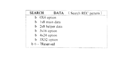
またメインデータが、サーチ用データ(SEARCH)の場合、b7〜b5ビットは値6に設定され、b4はリザーブに設定される。またb3〜b1ビットには、対応するサーチ速度が記録され、b0ビットにスクランブル制御のオン状態を示すフラグSBSCが割り当てられる。なおサーチ用データは、Iピクチャーの低域成分によるデータであり、b3〜b1ビットが値2及び4のとき、それぞれ8倍及び24倍のサーチ速度を指示するようになされている。なおb3〜b1ビットの値7は、リザーブに割り当てられる。
【0031】
図8は、このようにして形成されるメインセクタのデータ構造における平均的な論理データ配分を示す図である。ここでC2符号は、連続エラー訂正能力を2トラック以上(=12.5%(=2トラック/16トラックECC (Error Correcting Code)インターリーブ))となるように、18個のシンクブロックに割り当てられ、これにより12.7〔%〕に設定される。補助データ(AUX)+NULLデータは、95バイト×2.2SB×300トラック×8ビット=501〔Kbps〕、ビデオデータは、95バイト×110SB×300トラック×8ビット=25.021〔Mbps〕、オーディオデータは、95バイト×1.8SB×300トラック×8ビット=421〔Kbps〕、サーチデータは、95バイト×9.1SB×300トラック×8ビット=2.07〔Mbps〕であり、総計28.044〔Mbps〕(95バイト×123SB×300トラック×8ビット)に設定される。なお以下において、シンクブロックは、適宜、SBにより示す。
【0032】
これらにより磁気テープには、順次、ビデオデータ、オーディオデータ、対応するシステムデータ(補助データ)がメインセクタのメインデータに割り当てられて記録されるようになされている。
【0033】
図9は、補助データをメインデータに割り当てる場合について、シンクブロック構造を示す図表である。各シンクブロックにおいては、補助データのモード(AUX mode)が値0(補助データがビデオデータに関する補助データの場合(AUX-V ))、値1(補助データがPESオーディオデータに関する補助データの場合(AUX-A ))、又は値5の場合(大容量メタデータが割り当てられている場合(AUX-M ))、各シンクブロックにおいては、シンクヘッダに続いて、メインデータエリアの先頭1バイトがサブヘッダに割り当てられる(図9(A)及び(B))。
【0034】
ここでサブヘッダは、b7〜b4がリザーブに割り当てられ、b3〜b0が一連のカウント値(CC.Continuity counter )に割り当てられる。ここでサブヘッダは、補助データが複数のシンクブロックに跨がって割り当てられた場合に、カウント値(CC.Continuity counter )によりデータの連続性を検出することを目的として設けられる。これによりこのカウント値は各補助データのモード毎に、それぞれ独立にカウント値を設定することにより、補助データを不規則に複数配置した場合でも、確実に再生できるようになされている。因みに、ECCTBパケットにおいては、システムデータである補助データを記録するものであるものの、規則的に配置され、かつデータに連続性を有することにより、サブヘッダが設けられないようになされている。ここでECCTBパケットは、ECCブロックの先頭の記録に割り当てられるシンクブロックであり、詳細については後述する。
【0035】
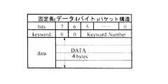
このようにしてメインセクタに割り当てられるデータのうち、補助データにおいては、図10及び図11に示すパケット構造により、図4について上述したメインデータに割り当てられる。
【0036】
ここで図10及び図11は、それぞれ固定長による補助データのパケット構造と可変長による補助データのパケット構造とを示す図表である。固定長によるパケット構造は、メインセクタにも適用されるものの、主にサブコードセクタに適用される。固定長によるパケット構造においては、全体が5バイトにより形成され、先頭1バイトのb7及びb6ビットが値0に設定され、b5〜b0ビットに、各補助データの内容を示すキーワード番号(keyword Number)が割り当てられ、残り4バイトが補助データに割り当てられる。
【0037】
これに対して可変長のパケット構造は、先頭1バイトのb7及びb8ビットがそれぞれ値0及び値1に設定され、b5〜b0バイトに、各補助データの内容を示すキーワード番号(keyword Number)が割り当てられる。また続く1バイトに、続く補助データのバイト数nが記録され、これによりパケット長を検出できるようになされ、続いてこのnバイトの補助データが割り当てられるようになされている。
【0038】
図12は、この固定長によるパケット構造におけるキーワード番号を示す図表である。キーワード番号は、固定長によるパケット構造と可変長によるパケット構造とで一連の番号が割り当てられ、固定長によるパケット構造には、値0〜値63が割り当てられる。これらのうち値0〜値7は、サブコードセクタに適用され、値0は、続く4バイトがタイトルタイムコード(TTC(ビデオデータ、オーディオデータの時間情報である))であることを示すようになされている。またキーワード番号の値1は、続く4バイトがバイナリーグループによるデータであることを示し、キーワード番号の値2は、続く4バイトがパート番号であることを示すようになされている。
【0039】
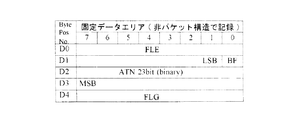
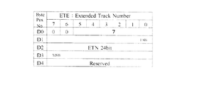
これに対してキーワード番号の値4は、続く4バイトがテープ位置情報(ATNF)、所定のフラグ(FLG )であることを示すようになされている。ここでテープ位置情報は、23ビットの絶対位置情報であり、テープ先頭からカウントした各記録トラックまでのトラック番号(ATN:Absolute Track Number )により表される。またフラグ(FLG )は、テープ位置情報が連続していないときに値1にセットされ、これによりトラック列の連続性を判断して確実にサーチできるようになされている。値5及び値6は、続く4バイトがそれぞれ記録日時、記録時間であることが示され、値7は、続く4バイトが拡張トラック番号(ETN:Extened Track Number)であることを示すようになされている。
【0040】
ここで拡張トラック番号ETNは、磁気テープからビデオデータを再生する再生基準の管理情報であり、デコード時におけるビデオデータの時刻管理情報DTS(Decoding Time Stamp )に対して比例関係となるように、またこのデコード時における動作基準であり、さらにはこのビデオテープレコーダ1の動作基準であるシステムタイムクロックSTC(System Time Clock )に対して比例関係となるように、以下の関係式により、時刻管理情報DTSをトラック番号により表した値が適用される。拡張トラック番号(ETN)は、24ビットにより表され、b4〜b0ビットの内容が、ECC内のトラック番号となり、b5〜b1ビットの内容が、トラックペア番号(Track Pair Number )と一致するようになされている。なおここでECC内のトラック番号は、ECC先頭トラックに値0を設定してなる番号である。なおこのデコード時における時刻管理情報DTSは、周波数90〔kHz〕によるカウント値であり、デコードされてデータ伸長したビデオデータの出力基準である。
【0041】
またタイトルタイムコード(TTC)との間では、フィールド周波数59.94〔Hz〕のシステムに適用した場合、TTCが10トラックの周期で繰り返し割り当てられ、TTCの書き始めにおいて、ETNが10の整数倍により表されるようになされている。またフィールド周波数50〔Hz〕のシステムに適用した場合、TTCが12トラックの周期で繰り返し割り当てられ、TTCの書き始めにおいて、ETNが12の整数倍により表されるようになされている。
【0042】
これにより拡張トラック番号は、この実施の形態においては、フィールド周波数59.94〔Hz〕のシステムに適用した場合、DTS=EFN×3003=ETN×3003/10により表され、またフィールド周波数50〔Hz〕のシステムに適用した場合、DTS=EFN×3600=ETN×3600/12により表されるようになされている。なおEFNは、Extended Frame Number であり、拡張トラック番号ETNに対応するフレーム番号である。なお第1のIDにおいて、値8〜値62はリザーブに割り当てられ、値63は、続く4バイトがNULLであることを示すようになされている。
【0043】
これに対して図13は、可変長によるパケット構造におけるキーワード番号を示す図表である。可変長によるパケット構造には、値64〜値127が割り当てられる。これらのキーワード番号のうち、値64〜値67は、オーディオデータの補助データに割り当てられ、値64において、続く可変長のデータにオーディオデータの補助データが割り当てられていることを示すようになされている。なお残り値65〜値67は、リザーブに割り当てられる。
【0044】
これに対して値68〜値79は、ビデオデータの補助データに割り当てられ、値68においては、続く可変長のデータにビデオデータの補助データが割り当てられていることを示すようになされ、また値73は、続く可変長のデータがDV方式と互換性のあるデータであることを示すようになされている。また値77及び値78は、それぞれ続く可変長のデータがアスキーコード及びシフトJISコードによるメッセージのデータであることを示すようになされ、値79は、続く可変長のデータがバイナリーデータであることを示すようになされている。
【0045】
これに対して値80〜83は、システム用に割り当てられ、値80は、続く可変長データによりECCTBパケットが形成されることを示すようになされている。また値84〜値119は、リザーブであり、値120〜値126は、続く可変長データが大容量のメタデータであることを示すようになされている。また値127は、続く可変長データがNULLであり、全体としてNULLパケットを形成することが示されるようになされている。
【0046】
図14は、このようなキーワード番号の設定のうち、キーワード番号を値64に設定してなるオーディオフレームパケットを示す図表である。オーディオフレームパケットは、図11のパケット構造について上述したように、先頭1バイトが値64のキーワード番号に設定され、続く1バイトに続くバイト数n(=92)が割り当てられる。さらに続いてトランスポートストリームを出力するための動作モードが設定され、続く5バイト、3バイト、5バイトには、対応するビデオフレームと同一内容によるVTRモード、テープ位置情報(ATNF)及び各種のフラグ(EFL、FLG)、タイトルタイムコードが割り当てられる。これによりパックユニットにおいて、対応するビデオデータのパックペアを簡易に特定できるようになされている。ここでパックユニットは、対応するビデオデータ、オーディオデータ、システムデータの組み合わせを意味する。なおこの各種のフラグ(EFL、FLG)については、後述するサブコードの対応するパケットの説明において詳述する。
【0047】
また続く10バイトにオリジナルの記録日時、時間の情報が、続く8バイトに磁気テープへの記録日時、時間の情報が割り当てられ、続く1バイトにコピー世代を示す情報が割り当てられる。また続く2バイトに編集点に係るステータスの情報(編集情報)が各1バイトづつ割り当てられ、続く6バイトにオーディオのモードが割り当てられる。ここでオーディオのモードは、フレームサイズ、サンプリング周波数等である。また続く4バイトはリザーブに割り当てられ、続く11バイトにパックユニットに係る情報が割り当てられるようになされている。ここでこのパックユニットに係る情報においては、デコード基準の情報であり、フレーム番号、フレーム数、PTS(Presentation Time Stamp )である。なおここでPTSは、デコードによりデータ伸長したビデオデータ、オーディオデータの再生出力の時刻管理情報である。
【0048】
これに対して図15は、このようなキーワード番号の設定のうち、キーワード番号を値68に設定してなるビデオフレームパケットを示す図表である。ビデオフレームパケットは、図11のパケット構造について上述したように、先頭1バイトが値68のキーワード番号に設定され、続く1バイトに続くバイト数n(=92)が割り当てられる。さらに続いてトランスポートストリームを出力するための動作モードが設定され、続く5バイト、3バイト、5バイトには、対応するオーディオフレームと同一内容によるVTRモード、テープ位置情報(ATNF)及び各種のフラグ(EFL、FLG)、タイトルタイムコードが割り当てられる。
【0049】
また続く5バイトにバイナリーのタイムコードが割り当てられ、続く10バイト及び8バイトにそれぞれオリジナルの記録日時、時間及び磁気テープへの記録日時、時間の情報が割り当てられ、続く1バイトにコピー世代を示す情報が割り当てられる。ビデオフレームパケットは、4バイト目から39バイト目までに、DTSによる時刻管理情報が割り当てられるサブコードデータがそのまま割り当てられ、対応するビデオデータがBピクチャー、Cピクチャーの場合、これらのデータは、対応するIピクチャー又はPピクチャーにそのまま対応するようになされている。
【0050】
これに対して続く2バイトには、編集点に係るステータスの情報(編集情報)が各1バイトづつ割り当てられ、続く1バイトにはサーチ用データの記録モードが割り当てられる。なおサーチ用データは、図16に示すように、各サーチ速度に対応して割り当てられるようになされている。また続く11バイトにパックユニットに係る情報が割り当てられるようになされている。ここではこのパックユニットに係る情報は、MPEGビデオストリームヘッダの内容が割り当てられるようになされている。これらのデータのうち、ピクチャーに係る情報DATA−Hには、図17に示すように、Iピクチャー、Pピクチャー等を示す情報、記録終りを示す情報(V−END)が割り当てられるようになされている。
【0051】
これに対して続く16バイトは、ビデオモードの情報が割り当てられ、続く1バイト及び15バイトにはフレーム単位の付加情報(Extended DV Pack)が割り当てられるようになされている。
【0052】
図18は、キーワード番号を値80に設定してなるECCTBパケットを示す図表である。ECCTBパケットは、インターリーブ単位である16トラックに記録された情報が割り当てられ、上述したようにインターリーブの先頭、固定位置に記録される。ECCTBパケットは、図11のパケット構造について上述したように、先頭1バイトが値80のキーワード番号に設定され、続く1バイトに続くバイト数n(=93)が割り当てられる。さらに続く37バイトに、インターリーブの先頭トラックのサブコードと同一内容による情報が記録される。ここでこの情報は、テープ位置情報(ATNF)及び各種のフラグ(EFL、FLG)、ETN、タイトルタイムコード(TTC)、バイナリーグループ、オリジナルの記録日時、時間の情報、磁気テープへの記録日時、時間の情報、コピー世代を示す情報が割り当てられる。
【0053】
また続く25バイトにビデオに係る編集の情報が割り当てられ、編集点に係るステータス、サーチデータのモード等が割り当てられた後、ビデオ及びオーディオデータの情報(video mode)(audio mode)が割り当てられるようになされている。
【0054】
図19は、メインデータにサーチ用データを割り当てる場合について、サーチデータのシンクブロック構造を示す図表である。この場合、シンクブロックにおいては、先頭にサーチシンクブロックのヘッダが40ビット割り当てられ、残る720ビットにサーチ用のデータが割り当てられる。ここでこのヘッダには、リザーブの1ビットを間に挟んで、シンクブロック内に記録される先頭マクロブロック座標のXアドレス及びYアドレスが割り当てられる。続いてパケットID(PC ID)、パケットヘッダ、パケットデータが割り当てられる。
【0055】
ここでパケットヘッダは、パケットデータの内容を示すように設定され、図20に示すように、値2〜値7によりキーワード番号について上述したと同一の各種表示用の情報が示され、また値8〜値11に検索用の位置情報が示されるようになされている。
【0056】
図21は、サブコードセクタの構造を示す図表である。サブコードセクタは、例えば200倍程度の高速サーチに利用され、24−25変換後で、全体が1250ビットにより構成され、10個のサブコードシンクブロックで構成される。各サブコードシンクブロックは、先頭16ビットがシンクに割り当てられ、続く24ビットがIDに割り当てられる。さらに続く40ビットがサブコードデータに割り当てられ、残り40ビットがパリティに割り当てられる。
【0057】
シンクは、図22に示すように、メインセクタのシンクM0、M1とは異なる所定のパターンS0と、このパターンS0に対してビットを反転してなるパターンS1とが割り当てられるようになされ、これによりメインセクタとサブコードセクタとを識別できるようになされている。
【0058】
サブコードセクタのIDは、図23に示すように、第1〜第3のID0〜ID2により構成される。第1のID0は、メインセクタのシンクIDと同様に、フォーマットタイプ(F TYPE)及びトラックペア番号をそれぞれ定義するようになされている。また第2のID1は、サブコードセクタにおける各サブコードシンクブロックの番号(SB number )とリザーブとに割り当てられ、第3のID2は、メインセクタのシンクIDと同様に、オーバーライトプロテクトが割り当てられる。なおオーバーライトプロテクトの設定により、サブコードセクタに記録されているデータが前の消し残りと判断された場合、そのシンクブロックは無効なものとして処理されるようになされている。
【0059】
図24は、各サブコードセクタのサブコードデータの内容を示す図表である。各サブコードセクタは、図10について上述した固定パケット構造により、この図24に示す情報が記録される。ここでサブコードデータは、それぞれ偶数番目及び奇数番目のトラックペアで同一のデータが、図10について上述した固定長データ形式により記録される。但し、サブコードシンクブロック番号0、4、9については、図10について上述したパケット構造とは異なる構造により形成される。ここで偶数番目及び奇数番目のトラックペアにおけるサブコードシンクブロック番号0、4、9のサブコードには、各種のフラグ、テープ位置情報(ATNF)が割り当てられる。
【0060】
ここで図25は、このサブコードシンクブロック番号0、4、9に係るサブコードデータの構造を示す図表である。これらサブコードデータには、先頭1バイトに各種フラグが記録される。ここで図26は、このフラグの設定を示す図表であり、サーチデータの有無、メインデータとの間の位相差が記録されるようになされている。
【0061】
これに対して2バイト目、b0ビットには、テープ先頭を基準にしたトラック番号(ATN)が不連続であることを示すフラグBF(Blank Flag)が設定される。なおこれによりフラグBFは、一旦不連続となった以降の記録では、同一の値に設定される。また3バイト目には、テープ先頭を基準にしたトラック番号(ATN)が割り当てられる。なおこのトラック番号(ATN)は、DV方式の場合と同一であり、先頭1ビットが符号に割り当てられる。
【0062】
最後の1バイトには、図27に示す各種のフラグが設定される。ここでこれらのフラグは、サーチポイントを示すIフラグ、静止画の記録開始位置がメインデータの場合に設定されるPフラグ、メインデータにIピクチャ又はPピクチャが割り当てられていることを示すPFフラグ、編集に係るEFフラグ等が割り当てられるようになされている。
【0063】
これに対して偶数番目のトラックペアにおけるサブコードシンクブロック番号1、6のサブコード、奇数番目のトラックペアにおけるサブコードシンクブロック番号5のサブコードには(図24)、拡張トラック番号(ETN:Extened Track Number)が割り当てられる。
【0064】
図28は、この拡張トラック番号ETNを割り当ててなるサブコードを示す図表である。このサブコードにおいては、先頭1バイト、b5〜b0ビットに対応するキーワード番号が割り当てられ、第3バイトに拡張トラック番号ETNが割り当てられるようになされている。
【0065】
これに対して偶数番目のトラックペアにおけるサブコードシンクブロック番号2、5、7のサブコード、奇数番目のトラックペアにおけるサブコードシンクブロック番号1、6のサブコードには(図24)、タイトルタイムコード(TTC)が割り当てられる。
【0066】
図29は、このタイトルタイムコードを割り当てるサブコードを示す図表である。このサブコードにおいては、先頭1バイト、b5〜b0ビットに対応するキーワード番号が割り当てられ、続くバイトに順次タイムコードの情報が割り当てられるようになされている。
【0067】
これに対して偶数番目のトラックペアにおけるサブコードシンクブロック番号3、8のサブコードには(図24)、何ら情報が割り当てられないようになされている。これに対して奇数番目のトラックペアにおけるサブコードシンクブロック番号2、7のサブコードには、記録日時の情報が割り当てられ、また奇数番目のトラックペアにおけるサブコードシンクブロック番号3、8のサブコードには、記録時間の情報が割り当てられるようになされている。
【0068】
図30は、このようなメインセクタ、サブコードセクタによる記録に関して、磁気テープ上におけるサーチ用データの配置を示す図表である。サーチ用データの記録位置は、インターリーブ後の物理的な位置で定義される。ここで8倍速用のサーチ用データは、1ECCバンク(16トラック)単位に1つの割合で配置される。
【0069】
具体的に、この8倍速用のサーチ用データは、ECC内トラック番号ETN[3:0]=0及び4の記録トラックに、17シンクブロック分の同一データ(データ番号17〜33)がそれぞれ2回ずつ繰り返し記録され、またECC内トラック番号ETN[3:0]=2の記録トラックに、残り17シンクブロックのデータ(データ番号0〜16)が3回繰り返されて記録され、これらにより1ECCバンクに34シンクブロック(データ番号0〜33)が割り当てられるようになされている。
【0070】
これに対して24倍速用のサーチデータは、3EECバンク(16×3=48トラック)単位で1つ配置される。記録位置は、サブコードFLE(Flag Extension)内のSPH(Search Phase)、2ビットの3進カウンタにより示される。この24倍速用のサーチデータは、ECC内トラック番号ETN[3:0]=11及び15の記録トラックに、8シンクブロック分のデータ(データ番号0〜3、8〜11)がそれぞれ4回、繰り返されて記録され、またECC内トラック番号ETN[3:0]=13の記録トラックに、4シンクブロック分のデータ(データ番号4〜7)が3回繰り返し記録され、これにより3ECCブロックに12シンクブロック分のデータが繰り返し記録されるようになされている。
【0071】
これらのサーチ用データは、図20について上述したサブコードにおける表示用TTC等により検索されて利用されるようになされている。
【0072】
図31は、このようなメインセクタ、サブコードセクタによる記録に関して、磁気テープ上におけるメインデータの記録のイメージを示す図表である。この実施の形態においては、MP@HL 、MP@H-14 等のMPEG方式によりデータ圧縮してなるビデオデータ及びオーディオデータを記録するようになされており、このデータ圧縮に係るGOPのIピクチャー、Pピクチャーによりビデオデータを区切ってブロック化し、各ブロックのビデオデータ、対応するオーディオデータ及び補助データを組み合わせてパックユニットが形成される。ここで図31の例においては、符号I、P、BによりそれぞれIピクチャー、Pピクチャー、Bピクチャーを示し、先頭Iピクチャーに続いて、B、B、P、B、B、P……の順でピクチャーが連続する場合であり、I、B、B、Pピクチャー比率が4:1:1:2の場合である。なおこの図においては、インターリーブ単位であるECC単位について、上下の数字によりECCブロックの番号を示し、またこの内側の英数字によりECC単位内におけるトラック番号を示す。
【0073】
磁気テープにおいては、各ECC単位の先頭トラック、先頭シンクブロックにECCTBパケット(符号Hにより示す)により補助データが記録される。また各パックユニットにおいては、オーディオデータに係る補助データ(符号Xにより示す)が記録された後、オーディオデータ(符号Aにより示す)が記録され、続いてビデオデータに係る補助データ(符号Uにより示す)が記録される。また続いてストリーミングの順に、各ピクチャーが記録される。因みに、オーディオデータが384〔Kbps〕の場合、オーディオデータは、平均、50シンクブロック配置される。
【0074】
また連続するパックユニットは、適切な遅延時間を確保する分、必要に応じてNULLデータによるシンクブロック、メインデータを間に挟んで、連続するように記録される。これによりこの実施の形態では、各パックユニットの先頭を、デコード時における時刻管理情報DTSにより決まる一定位置に記録するようになされている。
【0075】
具体的に、この実施の形態では、磁気テープ上における対応する時刻管理情報DTSに対して、デコード時における遅延時間(vbv (Video Buffering Verifier) delay)に所定のトラック分の先行量αを加算したトラック数以上で先行するように、NULLデータの記録により、各パックユニットの先頭を記録する。また各パックユニットの終了位置が、磁気テープ上における対応する時刻管理情報DTSに対して、必ず先行した位置となるようにする。なおここでは、このαを16トラックとした。
【0076】
すなわち図32に示すように、この実施の形態においては、ベースバンドであるビデオデータ(図32(B))がMPEG方式によりデータ圧縮され(図32(C))、ここでビデオデータのエンコードによる遅延時間(Video ENC delay )が発生する。なおここでは、連続するピクチャーをB、B、I、B、B、Pピクチャーにより符号化処理する場合である。これに対して対応するオーディオデータA1〜A4(図32(F))においても、データ圧縮処理され(図32(E))、ここでオーディオデータのエンコードによる遅延時間(Audio ENC delay )が発生する。なおここでA1〜A4は、オーディオデータのデータ圧縮単位である長さ24〔msec〕の各フレームを示すものである。またAXA及びAXVは、それぞれオーディオデータ及びビデオデータの補助データである。
【0077】
これらデータ圧縮されたビデオデータ及びオーディオデータは、対応する補助データと共にパックユニットを形成し、このパックユニットが時分割多重化処理され(図32(D))、磁気テープに記録される(図32(A))。この磁気テープへの記録時、これらオーディオデータA1〜A4においては、Iピクチャーと共にパックユニットを形成する末尾のオーディオデータA4における遅延時間が磁気テープ上における最も短い遅延時間となり、このIピクチャーによるパックユニットに続くパックユニットの先頭側に配置されるオーディオデータA1の遅延時間が磁気テープ上における最も長い遅延時間となる。これによりデコード時における遅延時間(vbv (Video Buffering Verifier) delay)においては、データ圧縮時における発生符号量、各種補助データ、サーチ用データの介挿等により種々に変化することが判る。
【0078】
これに対して図33は、各パックユニットにおけるパッキングの関係を示す図表である。この例は、ベースバンド入力のビデオデータにおける先頭Iピクチャーから記録した例であり(図33(A))、このベースバンド入力においては、I、B、Bピクチャー、対応するオーディオデータ、補助データによりパックユニットP1が形成され、この補助データとしてオーディオデータ及びビデオデータの補助データAUX−A及びAUX−V等が得られ、またタイトルタイムコードTTC等が生成されて補助データに割り当てられることになる。
【0079】
なおここでC0及びC1によるパックユニットEP1は、編集点のパックユニットEDIT PACK であり、編集で必要な遅延時間 vbv delayの整合のために挿入されるものである。なお図34は、これらパックユニットに係る一連のデータの関係をまとめたものである。
【0080】
矢印により関連を示すように(図33(A))、この実施の形態ではこれらのベースバンド入力に係る一連のデータが多重化処理され(図33(B))、各パックユニットがメインデータにより磁気テープに記録され、対応する補助データがサブコードデータにより磁気テープに記録される(図33(C))。このときメインデータによるストリームは、サブコードの時刻管理情報DTSに対して先行した位置に記録され、サブコードは、対応する時刻管理情報DTSによる位置に記録される。またサーチ用データは、対応するIピクチャー、対応する時刻管理情報DTS以降のECCバンクから記録される。なおここでビデオデータは、エンコード時、リオーダリングにより順序が入れ換えらえるが、オーディオデータ及び補助データは、入力順に磁気テープに記録される。
【0081】
ここでIピクチャーの先頭の拡張トラック番号ETNは、120とされる。これは、ストリーム先頭で正の値とするためであり、トラック番号(ATN)も同じである。因みに、拡張トラック番号ETN、トラック番号(ATN)を値0から始めて記録を開始すると、デコード時における遅延時間(vbv (Video Buffering Verifier) delay)とECCブロック分の時間とを加算した時間による磁気テープ上における時刻管理情報DTSは、30トラック〜110トラックとなる。しかしながらセルフエンコードの場合において、フィールド周波数が59.94〔Hz〕のシステムとフィールド周波数が50〔Hz〕のシステムとで拡張トラック番号ETN、トラック番号(ATN)とを共通化することを考慮し、これによりこれらのシステムにおけるフレームとトラックの最小公倍数が同一である値120を拡張トラック番号ETN、トラック番号(ATN)の先頭値に設定した。
【0082】
この実施の形態ではこのようにして磁気テープに記録してなるサブコードセクタの各補助データを基準にしてビデオデータ及びオーディオデータが再生されて復号される(図33(D))。またサーチ用データにおいては(図33(E))、対応するビデオデータのIピクチャーより生成されて、上述したように、対応するIピクチャー、対応する時刻管理情報DTS以降のECCバンクから記録される。
【0083】
これにより磁気テープ上において、メインデータとサブコードデータとは、図35に示す関係により表される。なおこの図35は、サブコードと対応するパックユニット先頭の記録位置相関を、パックユニット先頭のフレームに着目して図示したものである。因みに、フィールド周波数が59.94〔Hz〕のシステムの場合、サブコードは、1フレーム10トラック単位で構成され、フレーム内10トラックのサブコードデータは、図24について上述した構成により同一内容が繰り返し記録される。
【0084】
ここでメインデータは、磁気テープ上のDTSであるサブコードの拡張トラック番号ETNに対して、デコード時における遅延時間(vbv delay)と所定トラック分の先行量を加算した時間の分だけ先行して、かつパックユニットの末尾が時刻管理情報DTSによる位置を越えないように設定されるものの、上述したように、図35(D)から(E)に示すように、パックユニットの記録開始位置の変化が許容される。
【0085】
ここでこのこのような開始位置の変化分T1は、補助データ、サーチ用データの挿入により変化することにより、以下のように見積もることができる。なおこの場合、再生側の処理全体を遅らせることにより、時刻管理情報DTSによる時刻より後に、各パックユニットのデータをデコード可能とするシステムも考えられるが、この場合、基準の時刻を後に移動させただけであり、サブコードに記録されるデータにも余分な遅延が必要になることから、処理が煩雑になる。
【0086】
ここでこのような開始位置の変化分T1に変化を与える要素のうち、サーチ用データの粗密による変化量は、上述したように、8倍速用及び24倍速用の双方で、最大1.6トラックとなり、また対応するオーディオデータのデータ量は最大で0.7トラックとなる。また補助データにおいては、3トラック/3フレームであり、NULLデータにおいては、パックユニットの記録開始位置をトラック単位で繰り下げた場合に、最大で1.0トラックとなる。これらを合計すると6.3トラックとなる。
【0087】
従ってこの実施の形態では、この所定トラック分による先行量αを6.3トラック以上に設定し、これによりビデオストリーム、オーディオストリームにおいて、途絶えることなく再生することができるようになされている。なおフォーマット規定は、更に拡張性を考慮し、この先行量αを16トラックとした。
【0088】
すなわちこの先行量αを6.3トラック以上の9〜12トラックに設定した場合、この余分なマージンにより、補助データ(AUX-M )をまとめて記録することができる。因みに、10トラック分である100〔KB〕程度のデータを間欠的に記録することが可能となる。また8倍速、24倍速用のサーチ用データの他、4倍速、16倍速等のサーチ用データを追加記録することが可能となる。因みに、このようにサーチ用データを追加記録すると、ビデオデータにおいては、その分、レートが低下することになる。また記録再生で、処理用のメモリを兼用するシステムにおいては、再生時、数フレーム分の余裕が発生し、これによりこの余裕を各種の処理に利用することができる。すなわち記録側においては、最大で4トラック先行するようにすれば、再生側においては、前述したような拡張されたフォーマットまで対応可能に、16トラック分のメモリ容量を確保することができ、この場合は、別途、システムを構成する場合に比して、メモリを約1フレーム分節約することができる。
【0089】
なおこの図35(A)、(B)及び(C)は、それぞれメインデータ、サブコードデータ、サーチ用データを示すものであり、また(D)及び(E)は、それぞれ最先行での記録及び最遅延での記録の例である。この図35においては、1秒を300トラックとして遅延時間(vbv delay)によるトラック数を表した。これらによりこの実施の形態においては、パックユニットの末尾はもとより、Iピクチャーの末尾においても、対応するDTS位置までの間に、期間T2の余裕を有するようになされている。
【0090】
ここでこのようなパックユニット先頭の設定に係る処理は、図31との対比により図36において符号Aにより示すように、デコード時における遅延時間(vbv delay )がトラック数に換算して62.7トラックである場合、少数点以下を切り捨てた62トラックにインターリーブのトラック数16を加算すると、78トラックのトラック数が得られる。これによりこの時刻管理情報DTSによる磁気テープ上の位置である拡張トラック番号ETNが値80の場合には、この拡張トラック番号ETNの位置から78トラック先行した位置である拡張トラック番号ETNが値2の位置から、対応するパックユニットを記録するようにNULLデータを割り当てる。なおこの図36においては、1フレームの期間に対応するトラック数が10トラックの場合であり、ECCTBパケットについては、記載を省略して示す。
【0091】
また符号Bにより示すパックユニットの先頭においては、デコード時における遅延時間(vbv delay )がトラック数に換算して50.4トラックの場合であり、この場合、同様にして得られるトラック数においては、値66である。また符号Aで示した場合より、トラック数においては、30トラック変化し、これによりETNは110となる。これによりETN=110より値66を減算して得られるETN=44の位置から、対応するパックユニットを記録するようにNULLデータを割り当てる。
【0092】
また符号Cにより示すパックユニットの先頭においては、デコード時における遅延時間(vbv delay )がトラック数に換算して57トラックの場合であり、この場合、同様にして得られるトラック数においては、値73であり、またETNは140であることにより、ETN=140より値73を減算すると、ETN=67が得られる。この場合、何らNULLデータを介挿しなくても、ETN=68となっており、記録開始位置を通過していることにより、この場合は、NULLデータを割り当てることなく、パックユニットを記録する。
【0093】
なおこのように連続するパックユニットが最先行記録開始位置より遅くなり、NULLを挿入する必要がなくなる理由としては、パックユニットを構成する3ピクチャーにおいて、データ圧縮による発生符号量が少ないことと、そのパックユニットのAUXデータ量が大きかった場合又はNULLデータの挿入により遅れ(最大1トラック)があった場合又はその間にサーチデータが記録された場合等複数の要因が重なった場合等である。
【0094】
(1−2)ビデオテープレコーダ
図37は、本発明の実施の形態に係るビデオテープレコーダの記録系を示すブロック図であり、図38は、この記録系の一部を詳細に示すブロック図である。このビデオテープレコーダ1においては、図1〜図36について上述したフォーマットによりMPEG方式、MP@HL、MP@14等によりビデオデータ及びオーディオデータをデータ圧縮して磁気テープ2に記録し、また再生してデコードする。
【0095】
すなわちこのビデオテープレコーダにおいて、映像データ圧縮部3は、制御部8によるレート制御により、順次入力されるビデオデータHDVをMPEG2(MP@H−14)に準拠した方式によりデータ圧縮し、各種時間情報等と共に出力する。すなわち映像データ圧縮部3は、ビデオエンコーダ3A、DTS/PTSジェネレータ(DTS/PTS GEN)3B、ETNジェネレータ(ETNGEN)3C、ビデオFIFO3D(図38)により構成される。このうちビデオエンコーダ3Aは、ビデオデータHDVをデータ圧縮し、ヘッダ、タイムスタンプ等を付加したPES信号によるビデオデータを出力する。DTS/PTSジェネレータ3Bは、ビデオデータHDVより時間情報を検出し、この時間情報により時刻管理情報DTS、PTSを出力する。ETNジェネレータ3Cは、このDTS/PTSジェネレータ3Bによる処理結果より上述した関係式により拡張トラック番号ETNを計算して出力する。またビデオFIFO3Dは、ビデオエンコーダ3Aから出力されるビデオデータを一時保持して出力する。なおこの実施の形態においては、15ピクチャーにより1GOPを形成し、さらにこのGOPの先頭Iピクチャーより3ピクチャー毎にPピクチャーを設定する。またこのGOPの他のピクチャーについては、Bピクチャーを設定する。
【0096】
サーチデータ発生部4は、このようにしてビデオデータよりIピクチャーを選択し、このIピクチャーによる符号化データより低周波成分のデータを選択することにより、サーチ用データを生成して出力する。
【0097】
音声データ圧縮部5は、ビデオデータHDVに対応するオーディオデータDAを入力し、このオーディオデータDAをMPEG Layer2に準拠した方式によりデータ圧縮し、256〜384〔Kbps〕のレートにより出力する。すなわち音声データ圧縮部5において、オーディオエンコーダ5Aは、オーディオデータDAをデータ圧縮して出力し、オーディオFIFO5Bは、このオーディオエンコーダ5Aの出力データを一時保持して出力する。
【0098】
補助データ発生部6は、補助データを生成して出力する。すなわち補助データ発生部6は、サブコード生成回路6A、ビデオ用の補助データ生成回路6B、オーディオ用の補助データ生成回路6Cにより構成される。これらのうちサブコード生成回路6Aは、ビデオデータHDV、オーディオデータDAと共に入力される各種の情報より対応する補助データを生成して出力する。これに対してビデオ用の補助データ生成回路6B、オーディオ用の補助データ生成回路6Cは、それぞれビデオエンコーダ3A、オーディオエンコーダ5Aから出力されるデータ圧縮されてなるビデオデータ、オーディオデータについて、補助データを生成して出力する。またECCTBジェネレータ(ECC TB GEN)6Dは、ECCTBパケットに必要な補助データを生成して出力する。
【0099】
多重化回路7は、これらデータ圧縮されてなるビデオデータ、オーディオデータ、サーチ用データ、補助データをNULLデータと共に多重化して出力する。すなわち多重化回路7において、NULLジェネレータ(NULL GEN)7Aは、例えば全ビットが所定の論理値に設定されてなるNULLデータを生成して出力し、マルチプレクサ(MUX)7Bは、このNULLデータ、FIFO5B、6Bから出力されるビデオデータ、オーディオデータ、サーチデータ発生部4、補助データ生成回路6Cから出力されるサーチ用データ、補助データを、コントローラ7Cの制御により、順次多重化して出力する。これによりこのビデオテープレコーダにおいては、シンクブロックを構成するデータ列を生成するようになされている。
【0100】
この処理においてコントローラ7Cは、各パックユニット単位で、補助データ、サーチ用データ等のデータ量を計算し、上述したデコード時における遅延時間(vbv delay )に応じて、NULLデータを介挿するように、マルチプレクサ7Bの動作を制御する。ECCメモリ7Dは、このマルチプレクサ7Bの出力データをECCブロック単位で一時保持し、所定順序により出力する。これによりECCメモリ7Dは、インターリーブの処理を実行する。またこれらの処理において、ECCTBパケット及びサブコードセクタを配置するタイミングで、ECCTBジェネレータ6Dの出力データ、ETNジェネレータ3C等の出力データを介挿して出力するようになされている。
【0101】
サブコード発生部10は、サブコードセクタにおけるサブコードのデータ列を生成して出力する。誤り符号ID付加部9は、多重化回路7の出力データ、サブコード発生部10の出力データに誤り訂正符号、ID等を付加し、これによりメインセクタ及びサブコードセクタのデータ列を生成する。すなわちサブコード発生部10においては、上述したETNジェネレータ3C、サブコード生成回路6A等により構成され、誤り符号ID付加部9において、ID、ECC付加回路9Aは、ECCメモリ7Dの出力データにID、誤り訂正符号を付加して出力する。ID、ECC付加回路9Bは、サブコード生成回路6Aの出力データにID、誤り訂正符号を付加して出力する。加算回路9Cは、これらID、ECC付加回路9A、9Bの出力データを1系統にまとめて、続く24−25変換部11に出力する。
【0102】
24−25変換部11は、この誤り訂正符号ID付加部9の出力データを24−25変調して出力する。シンク付加回路12は、24−25変換部11の出力データにシンクを付加して出力し、変調部、P/S変換部13は、このシンク付加回路12の出力データNRZI(Non Return to Zero Inverted )変調した後、シリアルデータ列に変換し、このシリアルデータ列により回転ドラムに搭載された磁気ヘッド14を駆動する。制御部8は、これら各回路ブロックの動作を制御するコントローラである。これらによりビデオテープレコーダ1では、上述したフォーマットにより順次ビデオデータ、オーディオデータ等を磁気テープ2に記録するようになされている。
【0103】
図39は、ビデオテープレコーダ1の再生系を示すブロック図であり、図40は、この再生系を部分的に詳細に示すブロック図である。この再生系において、ディジタル変換部、S/P変換部21は、磁気ヘッド14の出力信号を図示しない増幅回路により増幅した後、アナログディジタル変換処理して例えばビタビ復号することにより記録系における変調部、P/S変換部13の入力データを再生する。ディジタル変換部、S/P変換部21は、この再生したデータをパラレルデータに変換して出力する。
【0104】
復調部22は、記録時におけるNRZI変調に対応する処理により、ディジタル変換部、S/P変換部21の出力データを復調して出力する。シンク検出部23は、この復調部22の出力データより各シンクブロックのシンクを検出し、このシンク検出のタイミングを誤り訂正ID検出部24等に通知する。25−24変換部25は、ディジタル変換部、S/P変換部21の出力データを25−24変換処理することにより、記録系における24−25変換部11の入力データを再生して出力する。
【0105】
誤り訂正ID検出部24は、シンク検出部23によるシンク検出のタイミングを基準にして24−25変換部11の出力データID以下をIDから検出したSB番号、トラック番号によりECCバンク24Aに貼付け誤り訂正24Bにより誤り訂正処理とデインターリーブ処理をして出力する。すなわちECCバンク24Aの構成は入力データを書き込むためのもの、24BでECC処理するためのもの、分離回路27に出力するためのものの3バンク構成を持っている。
【0106】
サブコード検出部26は、サブコードシンクからサブコードをSB検出して誤り訂正を行い出力する。すなわちサブコード検出部26において、サブコードECC26Aは、24−25変換部11の出力データよりサブコードセクタのデータを選択的に取得して誤り訂正処理することにより、サブコードのデータを取得して出力し、サブコードFIFO26Bは、このサブコードのデータを制御部8である中央処理ユニット(CPU)8Aに出力する。
【0107】
分離回路27は、この誤り訂正ID検出部24の出力データをSBヘッダにより各処理系に分離して出力する。すなわち分離回路27において、SB検出回路27Aは、各SBを検出することにより、各シンクブロックのメインデータを検出し、デマルチプレクサ27Bは、このSB検出回路27Aの検出結果に基づいて誤り訂正ID検出部24の出力データを各処理系に出力する。
【0108】
映像データ伸長部28は、この分離回路27よりビデオデータを入力し、記録時とは逆に、このビデオデータをデータ伸長して出力する。すなわち映像データ伸長部28において、ビデオFIFO28Aは、分離回路27の出力データを一時保持して出力し、ビデオデコーダ28Bは、このビデオFIFO28Aの出力データをデータ伸長して出力する。これによりビデオテープレコーダ1では、再生結果であるビデオデータHDVを出力できるようになされている。
【0109】
この実施の形態において、このビデオデータを一時保持して出力するビデオFIFO28Aは、記録系において、各パックユニットの先頭の記録位置が、対応する再生基準の管理情報が記録されてなる記録位置に対して先行させた先行量に対応する容量以上であるように設定される。
【0110】
これに対してサーチデータ検出部29は、分離回路27よりサーチ用データを入力し、このサーチ用データよりビデオデータを生成して出力する。すなわちサーチデータ検出部29において、サーチデコーダ29Aは、分離回路27よりサーチ用データを入力し、取得できなかった部分は補間処理が行われ、ビデオデータを生成して出力する。サーチ補助データ検出回路29Bは、このサーチ用データに付加されてなる補助データを取得して中央処理ユニット8Aに通知する。
【0111】
音声データ伸長部30は、分離回路27よりオーディオデータを入力し、このオーディオデータをデータ伸長して出力する。すなわち音声データ伸長部30において、オーディオFIFO30Aは、分離回路27より出力されるオーディオデータを一時保持して出力し、オーディオデコーダ30Bは、このオーディオデータをデータ伸長して出力する。これによりこのビデオテープレコーダ1では、再生結果であるオーディオデータDAを出力できるようになされている。
【0112】
補助データ検出部31は、分離回路27より補助データを検出して制御部8に出力する。すなわち補助データ検出部31において、補助データFIFO31Aは、分離回路27より出力される補助データを一時保持して中央処理ユニット8Aに出力する。また補助データジェネレータFIFO31Bは、分離回路27より出力される補助データを一時保持し、ビデオデータ、オーディオデータ等の出力に対応するフォーマットに変換して中央処理ユニット8Aに出力する。
【0113】
かくするにつき制御部8は、記録系の場合と同様に、再生系についても、これらの回路ブロックを制御する。すなわちこの制御部8において、中央処理ユニット8Aは、図示しないメモリに記録された処理手順を実行することにより、これら全体の動作を制御する。この処理において、システムタイムクロックSTCジェネレータ8Bは、このビデオテープレコーダ1の動作基準であるシステムタイムクロックSTCを生成して出力し、基準ETNジェネレータ8Cは、このシステムタイムクロックSTCより比較基準のETNを生成して出力する。テープドラムサーボ回路8Dは、キャプスタンモータ8F、ドラムモータ8Eを回転駆動し、これにより磁気テープ2を所定速度で走行させると共に、この磁気テープ2を巻き付けてなる回転ドラムを所定速度により回転駆動する。この処理において、テープドラムサーボ回路8Dは、基準ETNジェネレータ8Cより得られる比較基準のETNと、復調部22の出力データより得られる再生結果によるETN(サブコード検出部26より得られるETNである)とを比較し、これらが一致するようにキャプスタンモータ8Fの回転位相を制御する。これによりビデオテープレコーダ1では、記録時と同一のトラックトレースにより磁気ヘッド14で磁気テープ2を走査するようになされている。
【0114】
(1−3)メインデータと補助データとの関係
このようにして磁気テープ2に順次各種メインデータ、対応するサブコードデータを記録するにつき、ビデオテープレコーダ1では、各パックユニットにおいては、ビデオデータHDV、オーディオデータDA、対応する補助データがパックユニット内で完結するように、メインセクタを構成し、上述したように、各パックユニットの先頭に、順次、オーディオデータDAの補助データ、オーディオデータDA、ビデオデータHDVの補助データをまとめて配置する。これによりこのビデオテープレコーダ1においては、再生時、簡易に補助データを検出できるようになされ、さらには各パックユニットの先頭に記録された補助データのみを用いて、1つのパックユニットについては、各種の時間情報等を補間演算処理できるようになされている。
【0115】
このようにして記録されるメインセクタの補助データにおいて、デコード時におけるビデオデータの時刻管理情報DTSに対応する再生基準の管理情報ETNにおいては(図14、図15、図33)、ベースバンドであるビデオデータHDVのピクチャーの順序で配置される。また同様に、時間情報であるTTC、REC TIME(図14、図15、図33)もビデオデータHDVのピクチャーの順序で配置される。これに対してサブコードセクタの補助データにおいて、再生基準の管理情報であるETN、ピクチャータイプの情報は、データ圧縮されてなるビデオデータのピクチャーの順序により配置される。また同様のサブコードセクタの補助データである時間情報TTC、REC TIMEについては、メインセクタと同一の順序により記録され、これによりメインセクタの対応する補助データとの間で相関が図れるようになされている。
【0116】
これによりビデオテープレコーダ1においては、再生時、順次、メインセクタ、サブコードセクタより再生される補助データを選択的に取得して、デコード、ビデオデータHDVの出力等の処理に供するようになされている。
【0117】
これに対してサーチ用データに関する補助データは(図20)、磁気テープに記録されたビデオデータの検索用データについては、デコード時におけるビデオデータの時刻管理情報DTSを基準にして記録し、サーチ用データによる画像と共に表示する表示用データについては、ビデオデータHDVの再生出力の時刻管理情報PTSを基準にして記録する。
【0118】
すなわちビデオテープレコーダ1は、このような補助データのうち、検索用データとしては、対応するビデオデータの記録位置を示すテープ位置情報ATN、対応するビデオデータの再生基準の管理情報ETNを、時刻管理情報DTS基準で生成する。これに対して表示用データであるTTC、REC TIME等は、再生出力の時刻管理情報PTSを基準にして生成する。またビデオテープレコーダ1は、サーチ用データによるビデオデータを出力する際に、ユーザーによる指示により、これら表示用データによる各種の情報をオンスクリーン表示するようにビデオデータを処理して出力する。
【0119】
これらによりこの実施の形態において、ビデオエンコーダ3A、オーディオエンコーダ5Aは、ビデオデータ及びオーディオデータをデータ圧縮して圧縮ビデオデータ及び圧縮オーディオデータを生成するデータ圧縮手段を構成するのに対し、マルチプレクサ7Bは、圧縮ビデオデータを所定のピクチャー数単位でブロック化し、該ブロックの圧縮ビデオデータと、対応する圧縮オーディオデータと、対応する補助データとの組み合わせによるパックユニットを生成するパックユニット生成手段を構成するようになされている。またマルチプレクサ7B以降の回路ブロックにおいては、パックユニットによるデータをメインセクタに割り当て、パックユニットの補助データをサブコードセクタに割り当て、メインセクタ及びサブコードセクタによる記録トラックを順次形成する記録系を構成するようになされている。
【0120】
またサーチデータ発生部4は、ビデオデータにおけるフレーム内符号化処理によるピクチャーのデータより、サーチ用データを生成するサーチ用データ生成手段を構成し、またETNジェネレータ3C等と共に、サーチ用データに関連するサーチ用の補助データを生成する補助データ生成手段を構成するようになされている。
【0121】
(2)実施の形態の動作
以上の構成において、このビデオテープレコーダ1では(図37及び図38)、記録時、ビデオデータHDV、オーディオデータDAがそれぞれ映像データ圧縮部3を構成するビデオエンコーダ3A、音声データ圧縮部5を構成するオーディオエンコーダ5AでMPEG方式によりデータ圧縮され、PESトランスポートストリームによるビデオデータ及びオーディオデータが生成される。またサーチデータ発生部4であるサーチジェネレータ4において、このようにしてデータ圧縮してなるビデオデータのIピクチャーのデータより低周波数成分のデータが選択されて8倍速及び24倍速のサーチ用データが生成される。またビデオデータの各ピクチャーの情報、ビデオデータと共に入力された補助データ等によりサブコード生成用の補助データが補助データ発生部6で作成される。
【0122】
この補助データを作成する際に、ビデオテープレコーダ1では、DTS/PTSジェネレータ3Bにおいて、ビデオデータHDVを出力する際の基準である周波数90〔kHz〕による時刻管理情報DTSが生成される。またこの時刻管理情報DTSより、ビデオデータHDVがフィールド周波数59.94〔Hz〕の場合には、ETN=DTS/300.3の演算処理により、ビデオデータHDVがフィールド周波数50〔Hz〕の場合には、ETN=DTS/360の演算処理により、磁気テープ2に記録したデータ圧縮されてなるビデオデータを再生する再生基準の時間情報である拡張トラック番号ETNが生成される。
【0123】
ビデオテープレコーダ1では、これらデータ圧縮されたビデオデータ及びオーディオデータ、補助データ、サーチ用データがマルチプレクサ7Bで時分割多重化処理されてECCメモリ7Dに保持され、このECCメモリ7Dから所定の順序で出力されることにより、これらのデータがメインセクタのメインデータ、サブコードセクタにそれぞれ割り当てられてインターリーブ処理される。これらECCメモリ7Dの出力データは、続いてID、誤り訂正符号C1、C2が付加され、24−25変換部11で24−25変調された後、シンク付加回路12でシンクが付加され、これによりビデオデータ、オーディオデータ、一部の補助データ、サーチ用データにおいては、メインセクタ構造によるデータ列(図4)に変換される。これに対して補助データにおいては、同様のサブコードセクタ構造によるデータ列(図21)に変換される。さらにこのようにしてそれぞれメインセクタ構造によるデータ列、サブコードセクタ構造によるデータ列が変換部13でNRZI変調された後、シリアルデータ列に変換されて磁気テープ2に記録される。このときビデオテープレコーダ1においては、これらのデータ列にポストアンブル、プリアンブル等が途中で付加され、これにより図2のフォーマットにより順次磁気テープ2に斜め記録される。またこれらの処理において、磁気テープ2上における16トラックを単位にして、誤り訂正符号、インターリーブの処理を実行するように、ECCメモリ7Dが制御され、また誤り訂正符号が生成される。これによりビデオテープレコーダ1では、サブコードにDTS、STP、ETN等を割り当てて、対応するビデオデータ、オーディオデータが磁気テープ2に記録される。
【0124】
ビデオテープレコーダ1においては、このようにして磁気テープ2に記録するビデオデータが15ピクチャーによるGOPによりデータ圧縮され、さらにこの15ピクチャーによる1つのGOPを構成するビデオデータが3ピクチャー単位で区切られてビデオデータによるパックデータ(図34に示すPACK−V)が生成される。ビデオテープレコーダ1では、このビデオデータによるパックデータと、対応するオーディオデータ、補助データとによりパックユニットが形成され、このパックユニットを単位にしてビデオデータ、オーディオデータ、補助データが磁気テープ2に記録される(図31)。また各パックユニットにおいては、オーディオデータに関する補助データ、オーディオデータ、ビデオデータに関する補助データが先頭側に順次まとめられて順次磁気テープ2に記録される。これによりビデオテープレコーダ1では、パックユニット単位で磁気テープ2に記録されたビデオデータ等を処理することができるようになされている。
【0125】
ビデオテープレコーダ1においては、このようなパックユニットによる記録とは別に、各インターリーブ単位の先頭トラックの先頭シンクブロックには、補助データのECCTBパケットが割り当てられ、さらには一定位置に8倍速、24倍速のサーチ用データが記録され、これによりサーチ等の処理の向上が図られるようになされている。
【0126】
ビデオテープレコーダ1では、このようにしてパケット単位でビデオデータ、オーディオデータ、補助データを記録するにつき、各パックユニットにおいては、ビデオデータ、オーディオデータ、対応する補助データがパックユニット内で完結するように、メインセクタが構成され、各パックユニットの先頭に、順次、オーディオデータの補助データ、オーディオデータ、ビデオデータの補助データがまとめて配置される。これによりこのビデオテープレコーダ1においては、再生時、簡易に補助データを検出できるようになされ、さらには各パックユニットの先頭に記録された補助データのみを用いて、1つのパックユニットについては、各種の時間情報等を補間演算処理できるようになされている。
【0127】
すなわちこのようにパックユニットを単位として対応するデータが完結していない場合、ビデオデータの発生符号量が種々に変化することにより、磁気テープ上におけるこれらデータの対応関係を把握することが困難になる。特に、例えば所望する補助データを再生できない場合に補間演算処理により対応しようとしても、結局、連続するパックユニットの補助データを再生することが必要になる。しかしながらこの実施の形態のように、1つのパックユニットで完結し、さらにパックユニットの先頭に補助データを配置すれば、パックユニット内における補助データの補間演算処理により対応することができ、その分、処理を簡略化することができる。またつなぎ記録においても、記録済の対応する補助データを簡易に参照することができ、またこのような参照基準においても、パックユニット単位であることにより、簡易に検出することができる。
【0128】
また編集時にデータを書き戻しする場合、記録済のデータにつなぎ記録する場合でも、必要に応じて編集点以前のものを参照しなくてもよいことになり、その分処理、構成を簡略化することができる。またビデオデータ、オーディオデータ自体についても、パックユニット内で補間演算処理することができ、これによっても処理を簡略化することができる。
【0129】
ビデオテープレコーダ1では、このようにして記録される補助データにおいて、メインセクタにおいては、デコード時におけるビデオデータの時刻管理情報DTSに対応する再生基準の管理情報ETN、時間情報であるTTC、REC TIMEがビデオデータHDVのピクチャーの順序により配置されるのに対し、サブコードセクタの補助データにおいて、再生基準の管理情報であるETN、ピクチャータイプの情報が、データ圧縮されてなるビデオデータのピクチャーの順序により配置され、時間情報TTC、REC TIMEについては、メインセクタと同一の順序により記録される。
【0130】
これによりビデオテープレコーダ1では、再生時におけるデコード等の各処理に必要な補助データが、記録時、対応する部位に配置されて記録するようになされ、これにより再生時、単に再生された対応する補助データに従って各ピクチャー、オーディオデータを処理することにより、ビデオデータ、オーディオデータを再生し、デコードすることができ、その分、再生側の処理、構成を簡略化することができ、これにより全体を効率良く構成することができる。
【0131】
またこのように補助データを配置することにより、サブコードとストリームとの相関を簡易に把握できるようになされ、その分、全体構成を簡略化することができる。すなわちパックユニットの先頭のビデオデータの時刻管理情報DTSと、対応するサブコードの管理情報ETNとが比例関係であり、これにより対応関係を明確化することができ、さたにはこれによっても参照基準を明確化することができる。
【0132】
これに対してサーチ用データに関する補助データについては、検索用データであるテープ位置情報ATN、再生基準の管理情報ETNが、時刻管理情報DTS基準によりデコード時におけるビデオデータの時刻管理情報DTSを基準にして記録され、サーチ用データであるTTC、REC TIME等は、再生出力の時刻管理情報PTS基準によりビデオデータHDVの再生出力の時刻管理情報PTSを基準にして記録される。
【0133】
これによりビデオテープレコーダ1では、このようにサーチ用データについても、再生時における処理に対応する基準によりに記録され、これにより再生時、順次再生される表示用データを順次表示するだけで、時系列により所望するシーンを簡易に選択することができ、またこのようにしてシーンを検出して対応する検索用データにより簡易に頭出しすることができ、これにより再生側の構成を簡略化することができ、これにより全体を効率良く構成することができるようになされている。
【0134】
因みに、このような基準を切り換えることなく、例えばPTS基準だけでこれらの情報を記録した場合、サーチ用の画像を生成する際のエンコーダにおいては、煩雑な処理が必要になる。またIピクチャーのパックユニットにおける補助データをそのまま割り当てることも考えられるが、このようにするとサーチ用データにより形成される画像と、対応する時間情報TTC、REC TIME/DATEについては、リオーダリングに対応するように補正をすることが必要となり、複雑な演算処理が必要になる場合もある。因みに、桁上げ、ドロップフレームに対応する場合に、演算処理が煩雑になる。
【0135】
しかしながらこの実施の形態においては、このような補正等の処理を実行しなくても良く、これにより再生側の処理を簡略化することができる。これによりサーチ用データより所望するシーンを簡易に頭出しすることができる。
【0136】
(3)実施の形態の効果
以上の構成によれば、少なくとも再生基準の管理情報を、メインセクタでは再生出力するビデオデータのピクチャー順に、サブコードセクタでは、データ圧縮したビデオデータのピクチャーの順序に記録することにより、全体を効率良く構成することができる。
【0138】
(4)他の実施の形態
なお上述の実施の形態においては、NULLデータの記録によりメインストリームのデータを遅延させる場合について述べたが、本発明はこれに限らず、例えば同一のメインデータの繰り返しの記録によりメインストリームのデータを遅延させる場合等、種々の遅延手法に広く適用することができる。
【0139】
また上述の実施の形態においては、MPEGによりデータ圧縮したビデオデータを記録する場合について述べたが、本発明はこれに限らず、種々の方式によりデータ圧縮したビデオデータを記録する場合に広く適用することができる。
【0140】
【発明の効果】
上述のように本発明によれば、少なくとも再生基準の管理情報を、メインセクタでは再生出力するビデオデータのピクチャー順に、サブコードセクタでは、データ圧縮したビデオデータのピクチャーの順序で記録することにより、全体を効率良く構成することができる。また検索用データについて、デコード時におけるビデオデータの時刻管理情報を基準にして、表示用データについては、ビデオデータの再生出力の時刻管理情報を基準にして記録することにより、全体を効率良く構成することができる。
【図面の簡単な説明】
【図1】本発明の実施の形態に係るビデオテープレコーダにおけるテープフォーマットを示す平面図である。
【図2】図1のテープフォーマットにおけるセクタの配置を示す図表である。
【図3】プリアンブルのパターンを示す図表である。
【図4】メインセクタの構造を示す図表である。
【図5】シンクパターンを示す図表である。
【図6】IDを示す図表である。
【図7】シンクブロックヘッダを示す図表である。
【図8】メインセクタにおける平均的な論理データ配分を示す図である。
【図9】補助データをメインデータに割り当てる場合について、シンクブロック構造を示す図表である。
【図10】固定長によるパケット構造を示す図表である。
【図11】可変長によるパケット構造を示す図表である。
【図12】キーワード番号を示す図表である。
【図13】可変長によるパケット構造におけるキーワード番号を示す図表である。
【図14】オーディオフレームパケットを示す図表である。
【図15】ビデオフレームパケットを示す図表である。
【図16】サーチモードの説明に供する図表である。
【図17】サーチ用データの説明に供する図表である。
【図18】ECCTBパケットを示す図表である。
【図19】メインデータにサーチ用データを割り当てる場合について、シンクブロック構造を示す図表である。
【図20】パケットヘッダを示す図表である。
【図21】サブコードセクタの構造を示す図表である。
【図22】サブコードセクタのシンクを示す図表である。
【図23】サブコードセクタのIDを示す図表である。
【図24】サブコードセクタのサブコードデータの内容を示す図表である。
【図25】サブコードシンクブロック番号0、4、9に係るサブコードデータの構造を示す図表である。
【図26】フラグの設定を示す図表である。
【図27】最下位ビットのフラグの設定を示す図表である。
【図28】拡張トラック番号を割り当ててなるサブコードを示す図表である。
【図29】タイトルタイムコードを割り当てるサブコードを示す図表である。
【図30】サーチ用データの配置を示す図表である。
【図31】メインデータの記録のイメージを示す図表である。
【図32】メインデータの処理の説明に供する図表である。
【図33】パックユニットにおけるパッキングの関係を示す図表である。
【図34】パックユニットに係る一連のデータの関係をまとめた図表である。
【図35】メインデータとサブコードデータとの関係を示す図表である。
【図36】パックユニットの記録の説明に供する図表である。
【図37】記録系の構成を示すブロック図である。
【図38】図37の一部を詳細に示す図表である。
【図39】再生系の構成を示すブロック図である。
【図40】図39の一部を詳細に示す図表である。
【符号の説明】
1……ビデオテープレコーダ、2……磁気テープ、3……映像データ圧縮部、4……サーチデータ発生部、5……音声データ圧縮部、6……補助データ発生部、7……多重化回路、8……制御部、10……サブコード発生部、14……磁気ヘッド、26……サブコード検出部、27……分離回路、28……映像データ伸長部、29……サーチデータ検出部、30……音声データ伸長部、31……補助データ検出部[0001]
BACKGROUND OF THE INVENTION
The present invention relates to a video tape recorder and a recording method, and in particular, can be applied to a video tape recorder that records a video signal by HDTV (High Definition TeleVision) on a magnetic tape. According to the present invention, at least the reproduction reference management information is recorded in the order of the picture of the video data to be reproduced and output in the main sector, and in the subcode sector in the order of the picture of the video data compressed in data, thereby efficiently configuring the whole. Be able toThe
[0002]
[Prior art]
Conventionally, for example, Japanese Patent Laid-Open No. 2001-291335 has proposed a video tape recorder that records and reproduces an HDTV video signal (hereinafter referred to as an HD signal).
[0003]
In Japanese Patent Laid-Open No. 2001-291335, various signals related to HD signals are recorded in a head area of a plurality of tracks to be interleaved in units of P picture arrangement period, thereby effectively using a magnetic tape. For example, a video tape recorder that records an HD signal by using the video tape recorder is disclosed.
[0004]
[Problems to be solved by the invention]
However, video tape recorders that record this type of HD signal are considered to require further various ideas for practical use. Specifically, if the recording / reproducing system can be configured more efficiently, the entire configuration can be simplified and various processes can be simplified accordingly.
[0005]
The present invention has been made in consideration of the above points, and a video tape recorder capable of efficiently configuring the whole.And recording methodIs to try to propose.
[0006]
[Means for Solving the Problems]
In order to solve such a problem, the invention of
[0007]
MaClaims3In the invention, the pack unit is formed by combining the compressed video data, the corresponding compressed audio data, and the corresponding auxiliary data by applying the recording method to block the compressed video data in units of a predetermined number of pictures. A pack unit generating step for generating the data, and a recording step for assigning data by the pack unit to the main sector, assigning auxiliary data for the pack unit to the subcode sector, and sequentially forming recording tracks by the main sector and the subcode sector, The auxiliary data of the main sector is arranged with at least the reproduction standard management information corresponding to the time management information of the video data at the time of decoding in the order of the picture of the video data, and the auxiliary data of the subcode sector is at least the reproduction standard management information , Pic It is placed by the picture order of the compressed video data information YataipuThe
[0008]
According to the configuration of
[0009]
Accordingly, the claim 3With this configuration, it is possible to provide a recording method capable of efficiently configuring the whole.
[0010]
DETAILED DESCRIPTION OF THE INVENTION
Hereinafter, embodiments of the present invention will be described in detail with reference to the drawings as appropriate.
[0011]
(1) Configuration of the first embodiment
(1-1) Recording format
FIG. 1 is a plan view showing a recording format on a magnetic tape by a video tape recorder according to an embodiment of the present invention. In this video tape recorder, almost the same magnetic tape running system as that of a DV (Digital Video) video tape recorder is used. A pair of diagonal tracks (a track pair) with a negative azimuth angle are sequentially formed on the magnetic tape. In the figure, Head indicates the scanning direction of the magnetic head, and Tape travel is the traveling direction of the magnetic tape. The recording tracks are sequentially created at a speed of about 300 tracks / second, and the recording rate for the magnetic tape is set to about 40 [Mbps].
[0012]
On the magnetic tape, a recording track in which no pilot signal is recorded, a recording track in which a pilot signal having a frequency F0 is recorded, and a recording track in which a pilot signal having a frequency F1 is recorded are formed cyclically. As a result, the magnetic tape can be subjected to tracking control based on the pilot signal. The frequencies F0 and F1 are set such that the recording frequencies are 1/90 and 1/60 with respect to the recording frequency of the channel bits of the data recorded on each recording track.
[0013]
In this video tape recorder, 16 tracks are set as an interleave processing unit and an error correction processing unit (ECC block) in the track train formed in this manner, whereby data to be recorded on the 16 tracks is sequentially stored in one block. In summary, interleaving and error correction processing are executed in each block. In this recording track, a track pair number of
[0014]
FIG. 2 is a chart showing a sector format in each recording track formed as described above. In the recording track, a preamble, a main sector, a subcode sector, a postamble, and an overwrite merge are sequentially formed from the scanning start side of the magnetic head. As for the recording track, the range of the winding angle of 174 degrees of the magnetic tape around the rotating drum from the scanning start side is assigned to these preamble, main sector, subcode sector, and postamble. When recording video data with a field frequency of 59.94 [Hz] (when the rotating drum mounted on the magnetic head rotates at a rotational speed of 60 × 1000/1001 [Hz]) ), 134975-bit data is recorded, and when video data having a field frequency of 50 [Hz] is recorded (when the rotating drum rotates at a rotational speed of 60 [Hz]), 134850-bit data is recorded. Data is recorded.
[0015]
Here, the preamble is configured to record 1800 bits of data necessary for locking the PLL circuit during reproduction. FIG. 3 is a chart showing the recording pattern of the preamble. In this embodiment, a combination of the pattern A and the pattern B obtained by inverting the bit with respect to the pattern A is assigned to each recording track. As a result, the above-described combination of pilot signals is also formed.
[0016]
In the main sector, video data used at the time of normal reproduction or search is recorded in units of sync blocks described later, and a total of 130425 bits is secured. The subcode sector is applied to recording of a subcode which is data used for position search in high-speed search, and an area of 1250 bits is secured. In the postamble, when the rotating drum rotates at a rotation speed of 60 × 1000/1001 [Hz] (when the field frequency is 59.94 [Hz]), an area of 1500 bits is secured, and the rotating drum is When rotating at a rotational speed of 60 [Hz] (in the case of a field frequency of 50 [Hz]), an area of 1375 bits is secured and is configured the same as the preamble.
[0017]
Overwrite merge is provided for securing a margin at the time of overwriting, and an area for 1250 bits is secured.
[0018]
FIG. 4 is a chart showing the basic structure of the main sector. FIG. 4 shows the data amount before 24-25 modulation. Here, the main sector is composed of 141 sync blocks each having 888 bits (111 bytes), and each sync block has 1 at the head.6A bit sync, 24-bit ID is assigned and the last 80bitIn addition, a C1 code, which is an inner code of an error correction code in the product code format, is assigned. The main sector is 768 remaining in 123 sync blocks out of 141 sync blocks.bit8bitHeader (sync block header) and 760bitThe remaining 18 sync blocks are assigned a C2 code that is an outer code of an error correction code in the product code format.
[0019]
Here, the sync is provided to detect the head of each sync block, and the pattern M0 shown in FIG. 5 and the pattern M1 obtained by inverting the bit with respect to the pattern M0 are alternately assigned. Yes.
[0020]
On the other hand, the ID is provided as auxiliary data for error correction for identifying the sync block, and is formed by three types of ID0 to ID2 shown in FIG. That is, the first 0-7 bits of the ID are set to the first ID0, and the track pair number is represented by the first 0-4 bits of the first ID0.
[0021]
Further, the track format described above with reference to FIG. 2 is recorded in the ID by the first 5 to 7 bits of the first ID0. As a result, identification information relating to the track is assigned to the first ID.
[0022]
On the other hand, the second ID1 is a sync block.Position ofA sync block number for identifying is assigned.
[0023]
The
[0024]
FIG. 7 is a chart showing the sync block header. In the sync block header, the data type that is the type of main data is indicated by bits b7 to b5, and detailed information in each data type is indicated by bits b4 to b0. That is, when NULL data, which is meaningless data, is assigned to the main data to form an empty sync block, the b7 to b5 bits are set to the
[0025]
Also, when video data and audio data auxiliary data (AUX) is assigned to the main data, bits b7 to b5 are set to a value of 1. In this case, the auxiliary data mode (AUX mode) is assigned to bits b4 to b2. Here, when the auxiliary data is auxiliary data related to PES (Packetized Elementary Stream) video data (AUX-V), bits b4 to b2 are set to the
[0026]
Also, when the auxiliary data is the first half of an MPEG2-PES PSI (Program Specific Information) packet (PES-PSI1), the b4 to b2 bits are set to the
[0027]
Corresponding to these, in this case, the b1 bit is assigned a flag DF indicating an invalid recording area to be recorded in ECCTB, or a flag FRC indicating the polarity reversal of the frame boundary in the main data, and the b0 bit is assigned this sync bit. A flag SBSC indicating an ON state of the scramble control of the block header is assigned. The b1 bit is assigned to the flag FRC when the b4 to b2 bits have a value of 0 or 5, and is assigned to the flag DF when the b4 to b2 bits have a value of 4. Otherwise, the b1 bit is set to reserve.
[0028]
On the other hand, when the main data is video data conforming to the MPEG2-PES format (PES-VIDEO), bits b7 to b5 are set to the
[0029]
On the other hand, when the main data is the first half of the data recorded in the form of a transport stream (TS-1H), bits b7 to b5 are set to a
[0030]
When the main data is search data (SEARCH), bits b7 to b5 are set to a value of 6, and b4 is set to reserve. The corresponding search speed is recorded in bits b3 to b1, and a flag SBSC indicating the scramble control ON state is assigned to bit b0. The search data is data based on the low frequency component of the I picture, and when the b3 to b1 bits are 2 and 4, the search speed is instructed to be 8 times and 24 times, respectively. Note that the
[0031]
FIG. 8 is a diagram showing an average logical data distribution in the data structure of the main sector formed as described above. Here, the C2 code has a continuous error correction capability of 2 tracks or more (= 12.5% (= 2 tracks / 16 tracks ECC (Error Correcting Code) interleave)).)WhenThus, it is assigned to 18 sync blocks, so that 12.7 [%] is set. Auxiliary data (AUX) + NULL data is 95 bytes × 2.2SB × 300 tracks × 8 bits = 501 [Kbps], video data is 95 bytes × 110 SB × 300 tracks × 8 bits = 25.021 [Mbps], audio The data is 95 bytes × 1.8 SB × 300 tracks × 8 bits = 421 [Kbps], the search data is 95 bytes × 9.1 SB × 300 tracks × 8 bits = 2.07 [Mbps], and a total of 28. 044 [Mbps] (95 bytes × 123 SB × 300 tracks × 8 bits). In the following, the sync block is appropriately indicated by SB.
[0032]
Thus, video data, audio data, and corresponding system data (auxiliary data) are sequentially assigned to the main data of the main sector and recorded on the magnetic tape.
[0033]
FIG. 9 is a chart showing a sync block structure when allocating auxiliary data to main data. In each sync block, the auxiliary data mode (AUX mode) has a value of 0 (when the auxiliary data is auxiliary data related to video data (AUX-V)) and a value of 1 (when the auxiliary data is auxiliary data related to PES audio data ( AUX-A)) or value 5 (when large-capacity metadata is allocated (AUX-M)), in each sync block, the first byte of the main data area is the sub-header following the sync header. (FIGS. 9A and 9B).
[0034]
Here, in the subheader, b7 to b4 are allocated to reserve, and b3 to b0 are allocated to a series of count values (CC. Continuity counter). Here, the sub-header is provided for the purpose of detecting the continuity of data by the count value (CC.Continuity counter) when the auxiliary data is allocated across a plurality of sync blocks. Thus, the count value is set independently for each auxiliary data mode, so that even when a plurality of auxiliary data are irregularly arranged, the count value can be reliably reproduced. Incidentally, in the ECCTB packet, although auxiliary data which is system data is recorded, the sub-header is not provided by being regularly arranged and having continuity in the data. Here, the ECCTB packet is a sync block assigned to the first record of the ECC block, and details will be described later.
[0035]
Of the data allocated to the main sector in this way, auxiliary data is allocated to the main data described above with reference to FIG. 4 by the packet structure shown in FIGS.
[0036]
Here, FIGS. 10 and 11 are diagrams illustrating the packet structure of auxiliary data with a fixed length and the packet structure of auxiliary data with a variable length, respectively. Although the packet structure with a fixed length is applied to the main sector, it is mainly applied to the subcode sector. In a packet structure with a fixed length, the whole is formed by 5 bytes, and b7 and b of the first 1 byte6Bit is set to
[0037]
On the other hand, in the variable-length packet structure, b7 and b8 bits of the first 1 byte are set to
[0038]
FIG. 12 is a chart showing keyword numbers in the packet structure with this fixed length. As the keyword number, a series of numbers is assigned to a packet structure having a fixed length and a packet structure having a variable length, and
[0039]
On the other hand, the
[0040]
Here, the extended track number ETN is reproduction reference management information for reproducing video data from a magnetic tape, and is proportional to the time management information DTS (Decoding Time Stamp) of the video data at the time of decoding. The time management information DTS is expressed by the following relational expression so as to be proportional to the system time clock STC (System Time Clock) which is the operation reference at the time of decoding and further the operation reference of the
[0041]
When applied to a system with a field frequency of 59.94 [Hz] with respect to the title time code (TTC), TTC is repeatedly assigned with a period of 10 tracks, and ETN is an integer multiple of 10 at the beginning of TTC writing. It is made to be represented by. When applied to a system with a field frequency of 50 [Hz], TTC is repeatedly assigned with a period of 12 tracks, and ETN is represented by an integer multiple of 12 at the start of TTC writing.
[0042]
As a result, in this embodiment, the extension track number is expressed by DTS = EFN × 3003 = ETN × 3003/10 when applied to a system having a field frequency of 59.94 [Hz], and a field frequency of 50 [Hz]. ], It is expressed by DTS = EFN × 3600 = ETN × 3600/12. EFN is an Extended Frame Number, which is a frame number corresponding to the extended track number ETN. In the first ID, a
[0043]
On the other hand, FIG. 13 is a chart showing keyword numbers in a variable length packet structure.
[0044]
On the other hand, the
[0045]
On the other hand, the
[0046]
FIG. 14 is a chart showing an audio frame packet in which the keyword number is set to a
[0047]
In addition, the original recording date / time and time information are allocated to the subsequent 10 bytes, the recording date / time and time information to the magnetic tape are allocated to the subsequent 8 bytes, and information indicating the copy generation is allocated to the subsequent 1 byte. In addition, status information (editing information) related to the editing point is assigned to the subsequent 2 bytes, one byte each, and continues.6The byte is assigned an audio mode. Here, the audio mode includes a frame size, a sampling frequency, and the like. Further, the subsequent 4 bytes are allocated to reserve, and information related to the pack unit is allocated to the subsequent 11 bytes. Here, the information related to the pack unit is information on the decoding standard, which is a frame number, a frame number, and a PTS (Presentation Time Stamp). Here, PTS is time management information for reproduction output of video data and audio data decompressed by decoding.
[0048]
On the other hand, FIG. 15 is a chart showing a video frame packet in which the keyword number is set to the
[0049]
In addition, a binary time code is assigned to the subsequent 5 bytes, the original recording date and time, time, and the recording date and time information on the magnetic tape are assigned to the subsequent 10 bytes and 8 bytes, respectively, and the copy generation is indicated to the subsequent 1 byte. Information is assigned. In the video frame packet, subcode data to which time management information by DTS is assigned is assigned as it is from the 4th byte to the 39th byte, and when the corresponding video data is a B picture or a C picture, these data correspond to The I picture or the P picture is directly supported.
[0050]
On the other hand, status information (editing information) related to the editing point is assigned to each subsequent 2 bytes by 1 byte, and a search data recording mode is assigned to the subsequent 1 byte. The search data is assigned corresponding to each search speed as shown in FIG. Further, information relating to the pack unit is assigned to the following 11 bytes. Here, the information relating to the pack unit is assigned the contents of the MPEG video stream header. Of these data, information DATA-H relating to the picture is assigned information indicating I picture, P picture, etc., and information indicating the end of recording (V-END) as shown in FIG. Yes.
[0051]
On the other hand, the following 16 bytes are allocated video mode information, and the subsequent 1 byte and 15Additional information (Extended DV Pack) in units of frames is assigned to the bytes.
[0052]
FIG. 18 is a chart showing an ECCTB packet in which the keyword number is set to 80. In the ECCTB packet, information recorded in 16 tracks as an interleave unit is allocated, and is recorded at the head and fixed positions of the interleave as described above. As described above with reference to the packet structure of FIG. 11, the ECCTB packet has the first 1 byte set as the keyword number of
[0053]
Further, editing information related to video is allocated to the subsequent 25 bytes, and statuses related to editing points, search data mode, etc. are allocated, and then video and audio data information (video mode) (audio mode) is allocated. Has been made.
[0054]
FIG. 19 is a chart showing a sync block structure of search data in the case where search data is assigned to main data. In this case, in the sync block, 40 bits of the header of the search sync block are allocated at the head, and search data is allocated to the remaining 720 bits. Here, an X address and a Y address of the leading macroblock coordinates recorded in the sync block are assigned to this header with one bit of reserve interposed therebetween. Subsequently, a packet ID (PC ID), a packet header, and packet data are assigned.
[0055]
Here, the packet header is set so as to indicate the content of the packet data, and as shown in FIG. 20, the same information for various displays as described above for the keyword number is indicated by the
[0056]
FIG. 21 is a chart showing the structure of the subcode sector. The subcode sector is used for high-speed search of about 200 times, for example, and is composed of 1250 bits as a whole after 24-25 conversion, and is composed of 10 subcode sync blocks. In each subcode sync block, the first 16 bits are assigned to the sync, and the subsequent 24 bits are assigned to the ID. The subsequent 40 bits are assigned to subcode data, and the remaining 40 bits are assigned to parity.
[0057]
As shown in FIG. 22, the sync is assigned a predetermined pattern S0 different from the syncs M0 and M1 of the main sector and a pattern S1 obtained by inverting the bits with respect to the pattern S0. The main sector and the subcode sector can be identified.
[0058]
As shown in FIG. 23, the ID of the subcode sector includes first to third ID0 to ID2. The
[0059]
FIG. 24 is a chart showing the contents of the subcode data of each subcode sector. In each subcode sector, the information shown in FIG. 24 is recorded by the fixed packet structure described above with reference to FIG. Here, as the subcode data, the same data is recorded in the even-numbered and odd-numbered track pairs, respectively, in the fixed-length data format described above with reference to FIG. However, the subcode
[0060]
FIG. 25 is a chart showing the structure of the subcode data relating to the subcode
[0061]
On the other hand, a flag BF (Blank Flag) indicating that the track number (ATN) based on the head of the tape is discontinuous is set in the second byte and b0 bit. Thereby, the flag BF is set to the same value in the recording after the discontinuity once. The third byte is assigned a track number (ATN) based on the beginning of the tape. The track number (ATN) is the same as in the DV system, and the first bit is assigned to the code.
[0062]
Various flags shown in FIG. 27 are set in the last one byte. Here, these flags indicate an I flag indicating a search point, a P flag set when the recording start position of a still image is main data, and an I picture or a P picture is assigned to the main data.PFA flag, an EF flag related to editing, and the like are assigned.
[0063]
On the other hand, the subcode
[0064]
FIG. 28 is a chart showing a subcode to which the extended track number ETN is assigned. In this subcode, a keyword number corresponding to the first 1 byte and b5 to b0 bits is assigned, and an extended track number ETN is assigned to the third byte.
[0065]
On the other hand, the subcode
[0066]
FIG. 29 is a chart showing subcodes to which the title time code is assigned. In this subcode, a keyword number corresponding to the first 1 byte and bits b5 to b0 is assigned, and time code information is sequentially assigned to subsequent bytes.
[0067]
On the other hand, no information is assigned to the subcodes of the subcode
[0068]
FIG. 30 is a chart showing the arrangement of search data on the magnetic tape for such recording by the main sector and subcode sector. The recording position of search data is defined by the physical position after interleaving. Here, the search data for 8 × speed is arranged at a rate of one ECC bank (16 tracks).
[0069]
Specifically, the search data for 8 × speed includes 2 pieces of the same data (
[0070]
On the other hand, one 24 × speed search data is arranged in units of 3 EEC banks (16 × 3 = 48 tracks). The recording position is indicated by an SPH (Search Phase) 2-bit ternary counter in the subcode FLE (Flag Extension). The search data for 24 × speed is obtained by recording 8 sync blocks of data (
[0071]
These search data are searched for and used by the display TTC in the subcode described above with reference to FIG.
[0072]
FIG. 31 is a chart showing an image of main data recording on the magnetic tape regarding such recording by the main sector and subcode sector. In this embodiment, video data and audio data are recorded by data compression according to an MPEG method such as MP @ HL, MP @ H-14, etc., and an I picture of a GOP related to this data compression, Video data is divided into blocks by P-pictures, and a pack unit is formed by combining video data of each block, corresponding audio data, and auxiliary data. In the example of FIG. 31, I, P, and B pictures are indicated by symbols I, P, and B, respectively, followed by B, B, P, B, B, P. In this case, the pictures are continuous, and the I, B, B, P picture ratio is 4: 1: 1: 2. In this figure, with respect to the ECC unit which is an interleave unit, the ECC block number is indicated by upper and lower numerals, and the track number within the ECC unit is indicated by the inner alphanumeric characters.
[0073]
On the magnetic tape, auxiliary data is recorded by ECCTB packets (indicated by symbol H) in the head track and head sync block of each ECC unit. In each pack unit, auxiliary data (indicated by reference symbol X) relating to audio data is recorded, then audio data (indicated by reference symbol A) is recorded, and subsequently auxiliary data relating to video data (indicated by reference symbol U). ) Is recorded. Subsequently, each picture is recorded in the order of streaming. Incidentally, when the audio data is 384 [Kbps], the audio data is arranged in an average of 50 sync blocks.
[0074]
Further, consecutive pack units are recorded so that an appropriate delay time is ensured, with a sync block of NULL data and main data interposed therebetween as necessary. Accordingly, in this embodiment, the head of each pack unit is recorded at a fixed position determined by the time management information DTS at the time of decoding.
[0075]
Specifically, in this embodiment, the preceding amount α for a predetermined track is added to the delay time (vbv (Video Buffering Verifier) delay) at the time of decoding to the corresponding time management information DTS on the magnetic tape. The head of each pack unit is recorded by recording NULL data so that it precedes the number of tracks. In addition, the end position of each pack unit must be a position that precedes the corresponding time management information DTS on the magnetic tape. Here, α is 16 tracks.
[0076]
That is, as shown in FIG. 32, in this embodiment, video data as a baseband (FIG. 32 (B)) is compressed by the MPEG method (FIG. 32 (C)), where the video data is encoded. Delay time (Video ENC delay) occurs. Note that here, a case where continuous pictures are encoded by B, B, I, B, B, and P pictures is shown. On the other hand, the corresponding audio data A1 to A4 (FIG. 32F) is also subjected to data compression processing (FIG. 32E), where a delay time (Audio ENC delay) due to encoding of the audio data occurs. . Here, A1 to A4 indicate each frame of length 24 [msec], which is a data compression unit of audio data. AXA and AXV are auxiliary data of audio data and video data, respectively.
[0077]
The compressed video data and audio data form a pack unit together with corresponding auxiliary data, and this pack unit is time-division multiplexed (FIG. 32D) and recorded on the magnetic tape (FIG. 32). (A)). At the time of recording on the magnetic tape, in these audio data A1 to A4, the delay time in the last audio data A4 forming the pack unit together with the I picture becomes the shortest delay time on the magnetic tape, and the pack unit by this I picture The delay time of the audio data A1 arranged on the head side of the pack unit subsequent to the pack unit becomes the longest delay time on the magnetic tape. Thus, it can be seen that the delay time (vbv (Video Buffering Verifier) delay) at the time of decoding changes variously depending on the amount of generated code at the time of data compression, various auxiliary data, search data insertion, and the like.
[0078]
On the other hand, FIG. 33 is a chart showing the packing relationship in each pack unit. This example is an example of recording from the first I picture in the video data of baseband input (FIG. 33A). In this baseband input, I, B, B pictures, corresponding audio data, and auxiliary data are used. A pack unit P1 is formed, and auxiliary data AUX-A and AUX-V of audio data and video data are obtained as auxiliary data, and a title time code TTC is generated and assigned to auxiliary data.
[0079]
Here, the pack unit EP1 by C0 and C1 is an edit point pack unit EDIT PACK, which is inserted for matching the delay time vbv delay required for editing. FIG. 34 summarizes the relationship of a series of data related to these pack units.
[0080]
As shown by the arrows (FIG. 33A), in this embodiment, a series of data related to these baseband inputs is multiplexed (FIG. 33B), and each pack unit is based on the main data. Recorded on the magnetic tape, the corresponding auxiliary data is recorded on the magnetic tape by the subcode data (FIG. 33C). At this time, the stream based on the main data is recorded at a position preceding the time management information DTS of the subcode, and the subcode is recorded at a position based on the corresponding time management information DTS. The search data is recorded from the ECC bank after the corresponding I picture and the corresponding time management information DTS. Here, the order of video data can be changed by reordering during encoding, but the audio data and auxiliary data are recorded on the magnetic tape in the order of input.
[0081]
Here, the extension track number ETN at the head of the I picture is 120. This is for setting a positive value at the head of the stream, and the track number (ATN) is the same. By the way, when recording starts with the extended track number ETN and track number (ATN) starting from the
[0082]
In this embodiment, video data and audio data are reproduced and decoded based on each auxiliary data of the subcode sector recorded on the magnetic tape in this way (FIG. 3).3(D)). Further, the search data (FIG. 33E) is generated from the I picture of the corresponding video data and recorded from the ECC bank after the corresponding I picture and the corresponding time management information DTS as described above. .
[0083]
Thus, on the magnetic tape, the main data and the subcode data are represented by the relationship shown in FIG. FIG. 35 shows the recording position correlation at the head of the pack unit corresponding to the subcode, focusing on the frame at the head of the pack unit. Incidentally, in the case of a system with a field frequency of 59.94 [Hz], the subcode is configured in units of 10 tracks per frame, and the subcode data of 10 tracks in the frame has the same contents as described above with reference to FIG. To be recorded.
[0084]
Here, the main data precedes the extended track number ETN of the subcode which is a DTS on the magnetic tape by the time obtained by adding the delay time (vbv delay) at the time of decoding and the preceding amount for a predetermined track. Although the end of the pack unit is set so as not to exceed the position of the time management information DTS, as described above, as shown in FIGS. 35 (D) to (E), the change in the recording start position of the pack unit is changed. Is acceptable.
[0085]
Here, such a change T1 of the start position can be estimated as follows by changing by insertion of auxiliary data and search data. In this case, a system is also possible in which the data of each pack unit can be decoded after the time based on the time management information DTS by delaying the entire processing on the playback side. In this case, the reference time is moved later. In addition, since the data recorded in the subcode also requires an extra delay, the processing becomes complicated.
[0086]
Here, among the elements that change the starting position change T1, the amount of change due to the density of the search data is 1.6 tracks at maximum for both 8 × speed and 24 × speed as described above. In addition, the maximum amount of data of the corresponding audio data is 0.7 tracks. The auxiliary data has 3 tracks / 3 frames, and the NULL data has a maximum of 1. when the recording start position of the pack unit is lowered in units of tracks.0Become a track. The total of these is 6.3 tracks.
[0087]
Therefore, in this embodiment, the preceding amount α for the predetermined track is set to 6.3 tracks or more so that the video stream and the audio stream can be reproduced without interruption. In the format specification, the preceding amount α is set to 16 tracks in consideration of expandability.
[0088]
That is, when the preceding amount α is set to 9 to 12 tracks, which is 6.3 tracks or more, the auxiliary data (AUX-M) can be recorded collectively by this extra margin. Incidentally, it is possible to intermittently record data of about 100 [KB] corresponding to 10 tracks. Further, search data for 4 × speed, 16 × speed, etc. can be additionally recorded in addition to search data for 8 × speed and 24 × speed. Incidentally, if additional search data is recorded in this manner, the rate of video data is reduced accordingly. In a system that also uses a processing memory for recording and reproduction, a margin of several frames occurs during reproduction, and this margin can be used for various processes. In other words, if the recording side is preceded by a maximum of 4 tracks, the playback side can secure a memory capacity for 16 tracks so that it can support the extended format as described above. As compared with the case where a system is separately configured, the memory can be saved by about one frame.
[0089]
FIGS. 35A, 35B, and 35C show main data, subcode data, and search data, respectively, and FIGS. And an example of recording with the longest delay. In FIG. 35, the number of tracks according to the delay time (vbv delay) is shown with 1 second as 300 tracks. Thus, in this embodiment, not only at the end of the pack unit but also at the end of the I picture, there is a margin of the period T2 between the corresponding DTS positions.
[0090]
In this processing relating to the setting of the pack unit head, as shown by reference numeral A in FIG. 36 in comparison with FIG. 31, the delay time (vbv delay) at the time of decoding is converted to the number of tracks as 62.7. In the case of a track, when the
[0091]
Further, at the head of the pack unit indicated by the symbol B, the delay time (vbv delay) at the time of decoding is 50.4 tracks in terms of the number of tracks. In this case, in the number of tracks obtained in the same manner, A value of 66. Further, compared to the case indicated by the symbol A, the number of tracks is changed by 30 tracks, so that the ETN becomes 110. Thus, NULL data is allocated so as to record the corresponding pack unit from the position of ETN = 44 obtained by subtracting the
[0092]
In the head of the pack unit indicated by the symbol C, the delay time (vbv delay) at the time of decoding is 57 tracks in terms of the number of tracks. In this case, the
[0093]
The reason why the consecutive pack units are later than the earliest recording start position and there is no need to insert NULL is that the generated code amount due to data compression is small in the three pictures constituting the pack unit. This is the case when the amount of AUX data in the pack unit is large, when there is a delay (maximum 1 track) due to the insertion of NULL data, or when a plurality of factors overlap, such as when search data is recorded between them.
[0094]
(1-2) Video tape recorder
FIG. 37 is a block diagram showing a recording system of the video tape recorder according to the embodiment of the present invention, and FIG. 38 is a block diagram showing a part of this recording system in detail. In this
[0095]
That is, in this video tape recorder, the video
[0096]
In this way, the search
[0097]
The audio
[0098]
The auxiliary
[0099]
The
[0100]
In this process, the
[0101]
The
[0102]
The 24-25
[0103]
FIG. 39 is a block diagram showing a playback system of the
[0104]
The
[0105]
The error correction
[0106]
The
[0107]
The
[0108]
The video
[0109]
In this embodiment, the
[0110]
On the other hand, the search
[0111]
The audio
[0112]
The auxiliary
[0113]
Accordingly, the
[0114]
(1-3) Relationship between main data and auxiliary data
In this manner, when recording various main data and corresponding subcode data sequentially on the
[0115]
The auxiliary data of the main sector recorded in this way is the baseband in the reproduction reference management information ETN corresponding to the time management information DTS of the video data at the time of decoding (FIGS. 14, 15, and 33). The video data HDV are arranged in the order of pictures. Similarly, TTC and REC TIME (FIGS. 14, 15, and 33) as time information are also arranged in the order of pictures of the video data HDV. On the other hand, in the auxiliary data of the subcode sector, the ETN and picture type information, which are reproduction reference management information, are arranged in the order of the pictures of the video data that are compressed. In addition, time information TTC and REC TIME, which are auxiliary data of the same subcode sector, are recorded in the same order as the main sector, so that correlation can be achieved with the corresponding auxiliary data of the main sector. Yes.
[0116]
As a result, in the
[0117]
On the other hand, the auxiliary data relating to the search data (FIG. 20), the search data for the video data recorded on the magnetic tape is recorded with reference to the time management information DTS of the video data at the time of decoding, and the search data The display data to be displayed together with the image based on the data is recorded with reference to the time management information PTS of the reproduction output of the video data HDV.
[0118]
That is, the
[0119]
Thus, in this embodiment, the video encoder 3A and the
[0120]
The search
[0121]
(2) Operation of the embodiment
With the above configuration, in the video tape recorder 1 (FIGS. 37 and 38), during recording, the video data HDV and the audio data DA constitute the video encoder 3A and the audio
[0122]
When creating this auxiliary data, in the
[0123]
In the
[0124]
In the
[0125]
In the
[0126]
The
[0127]
That is, when the data corresponding to each pack unit is not completed in this way, the generated code amount of the video data changes variously, making it difficult to grasp the correspondence of these data on the magnetic tape. . In particular, for example, even if it is attempted to cope with interpolation processing when the desired auxiliary data cannot be reproduced, it is necessary to reproduce auxiliary data of successive pack units. However, as in this embodiment, if it is completed with one pack unit and auxiliary data is arranged at the head of the pack unit, it can be supported by interpolation calculation processing of auxiliary data in the pack unit. Processing can be simplified. Also, in the joint recording, it is possible to easily refer to the corresponding auxiliary data that has been recorded, and even in such a reference standard, it can be easily detected by the unit of the pack unit.
[0128]
In addition, when data is written back at the time of editing, it is not necessary to refer to the data before the editing point as necessary, even if it is connected to recorded data, and the processing and configuration are simplified accordingly. be able to. Also, video data and audio data themselves can be subjected to interpolation calculation processing in the pack unit, and this can also simplify the processing.
[0129]
In the
[0130]
Thereby, in the
[0131]
Further, by arranging the auxiliary data in this way, the correlation between the subcode and the stream can be easily grasped, and the entire configuration can be simplified accordingly. In other words, the time management information DTS of the video data at the head of the pack unit and the management information ETN of the corresponding subcode are in a proportional relationship, which makes it possible to clarify the correspondence, and also refer to this Criteria can be clarified.
[0132]
On the other hand, for the auxiliary data related to the search data, the tape position information ATN and the reproduction reference management information ETN which are the search data are based on the time management information DTS of the video data at the time of decoding based on the time management information DTS reference. The search data TTC, REC TIME, etc. are recorded with reference to the reproduction output time management information PTS based on the reproduction output time management information PTS standard.
[0133]
Thus, in the
[0134]
For example, when such information is recorded only by the PTS standard without switching such a standard, a complicated process is required in the encoder for generating the search image. Further, it is conceivable to assign auxiliary data in the pack unit of the I picture as it is. However, in this way, the image formed by the search data and the corresponding time information TTC, REC TIME / DATE correspond to reordering. It may be necessary to make corrections as described above, and complicated arithmetic processing may be required. Incidentally, the arithmetic processing becomes complicated when dealing with carry and drop frames.
[0135]
However, in this embodiment, it is not necessary to perform such processing as correction, and the processing on the reproduction side can be simplified. As a result, a desired scene can be easily found from the search data.
[0136]
(3) Effects of the embodiment
According to the above configuration, at least the reproduction reference management information is recorded in the order of the picture of the video data to be reproduced and output in the main sector, and in the subcode sector in the order of the data of the compressed video data, thereby improving the efficiency of the whole. Can be configured well.
[0138]
(4) Other embodiments
In the above-described embodiment, the case where the main stream data is delayed by the recording of NULL data has been described. However, the present invention is not limited to this. For example, the main stream data is recorded by repeatedly recording the same main data. The present invention can be widely applied to various delay methods such as delaying.
[0139]
In the above embodiment, the case of recording video data compressed by MPEG has been described. However, the present invention is not limited to this, and the present invention is widely applied to the case of recording video data compressed by various methods. be able to.
[0140]
【The invention's effect】
As described above, according to the present invention, at least the reproduction reference management information is recorded in the order of the video data picture to be reproduced and output in the main sector, and in the subcode sector in the order of the picture data of the compressed video data. The whole can be configured efficiently. Further, the entire data is efficiently configured by recording the search data with reference to the time management information of the video data at the time of decoding and the display data with reference to the time management information of the reproduction output of the video data. be able to.
[Brief description of the drawings]
FIG. 1 is a plan view showing a tape format in a video tape recorder according to an embodiment of the present invention.
FIG. 2 is a chart showing sector arrangement in the tape format of FIG. 1;
FIG. 3 is a chart showing a preamble pattern.
FIG. 4 is a chart showing a structure of a main sector.
FIG. 5 is a chart showing sync patterns.
FIG. 6 is a chart showing IDs.
FIG. 7 is a chart showing a sync block header.
FIG. 8 is a diagram showing an average logical data distribution in the main sector.
FIG. 9 is a chart showing a sync block structure when allocating auxiliary data to main data.
FIG. 10 is a chart showing a packet structure with a fixed length.
FIG. 11 is a chart showing a variable length packet structure.
FIG. 12 is a chart showing keyword numbers.
FIG. 13 is a chart showing keyword numbers in a variable length packet structure.
FIG. 14 is a chart showing an audio frame packet.
FIG. 15 is a chart showing a video frame packet.
FIG. 16 is a chart for explaining a search mode.
FIG. 17 is a chart for explaining search data.
FIG. 18 is a chart showing an ECCTB packet.
FIG. 19 is a chart showing a sync block structure in the case of assigning search data to main data.
FIG. 20 is a chart showing a packet header.
FIG. 21 is a chart showing a structure of a subcode sector.
FIG. 22 is a chart showing subcode sector sync.
FIG. 23 is a chart showing subcode sector IDs.
FIG. 24 is a chart showing the contents of subcode data in a subcode sector.
FIG. 25 is a chart showing a structure of subcode data according to subcode
FIG. 26 is a chart showing flag settings.
FIG. 27 is a chart showing setting of a flag of the least significant bit.
FIG. 28 is a chart showing subcodes to which extended track numbers are assigned.
FIG. 29 is a chart showing subcodes to which title time codes are assigned.
FIG. 30 is a chart showing the arrangement of search data.
FIG. 31 is a chart showing an image of recording main data.
FIG. 32 is a chart for explaining processing of main data.
FIG. 33 is a chart showing a packing relationship in the pack unit.
FIG. 34 is a chart summarizing the relationship of a series of data related to a pack unit.
FIG. 35 is a chart showing a relationship between main data and subcode data.
FIG. 36 is a chart for explaining recording of pack units.
FIG. 37 is a block diagram illustrating a configuration of a recording system.
FIG. 38 is a chart showing a part of FIG. 37 in detail.
FIG. 39 is a block diagram showing a configuration of a reproduction system.
40 is a chart showing a part of FIG. 39 in detail.
[Explanation of symbols]
1 ... video tape recorder, 2 ... magnetic tape, 3 ... video data compression unit, 4 ... search data generation unit, 5 ... audio data compression unit, 6 ... auxiliary data generation unit, 7 ... multiplexing Circuit: 8: Control unit, 10: Subcode generation unit, 14: Magnetic head, 26: Subcode detection unit, 27: Separation circuit, 28: Video data decompression unit, 29:
Claims (4)
前記ビデオデータ及びオーディオデータをデータ圧縮して圧縮ビデオデータ及び圧縮オーディオデータを生成するデータ圧縮手段と、
前記圧縮ビデオデータを所定のピクチャー数単位でブロック化し、該ブロックの前記圧縮ビデオデータと、対応する前記圧縮オーディオデータと、対応する前記補助データとの組み合わせによるパックユニットを生成するパックユニット生成手段と、
前記パックユニットによるデータをメインセクタに割り当て、前記パックユニットの前記補助データをサブコードセクタに割り当て、前記メインセクタ及びサブコードセクタによる前記記録トラックを順次形成する記録系とを備え、
前記メインセクタの補助データは、
少なくともデコード時における前記ビデオデータの時刻管理情報に対応する再生基準の管理情報を前記ビデオデータのピクチャーの順序により配置し、
前記サブコードセクタの補助データは、
少なくとも前記再生基準の管理情報、ピクチャータイプの情報を前記圧縮ビデオデータのピクチャーの順序により配置する
ことを特徴とするビデオテープレコーダ。In a video tape recorder that forms recording tracks obliquely on a magnetic tape and records video data, audio data, auxiliary data related to the video data and audio data on the magnetic tape,
Data compression means for compressing the video data and audio data to generate compressed video data and compressed audio data;
Pack unit generating means for blocking the compressed video data in units of a predetermined number of pictures and generating a pack unit by combining the compressed video data of the block, the corresponding compressed audio data, and the corresponding auxiliary data ,
A data recording system that assigns data by the pack unit to a main sector, assigns the auxiliary data of the pack unit to a subcode sector, and sequentially forms the recording tracks by the main sector and the subcode sector;
The auxiliary data of the main sector is
At least the reproduction reference management information corresponding to the time management information of the video data at the time of decoding is arranged in the order of the pictures of the video data,
The auxiliary data of the subcode sector is
A video tape recorder characterized in that at least the reproduction reference management information and picture type information are arranged in the order of pictures of the compressed video data.
前記再生基準の管理情報に加えて、前記ビデオデータ及び又は前記オーディオデータの時間情報を、前記ビデオデータのピクチャーの順序により配置し、
前記サブコードセクタの補助データは、
前記ビデオデータ及び又は前記オーディオデータの時間情報を、前記メインセクタの補助データに対応する順序により配置した
ことを特徴とする請求項1に記載のビデオテープレコーダ。The auxiliary data of the main sector is
In addition to the management information of the reproduction standard, the time information of the video data and / or the audio data is arranged according to the order of the pictures of the video data,
The auxiliary data of the subcode sector is
The video tape recorder according to claim 1, wherein time information of the video data and / or the audio data is arranged in an order corresponding to auxiliary data of the main sector.
前記ビデオデータ及びオーディオデータをデータ圧縮して圧縮ビデオデータ及び圧縮オーディオデータを生成するデータ圧縮ステップと、
前記圧縮ビデオデータを所定のピクチャー数単位でブロック化し、該ブロックの前記圧縮ビデオデータと、対応する前記圧縮オーディオデータと、対応する前記補助データとの組み合わせによるパックユニットを生成するパックユニット生成ステップと、
前記パックユニットによるデータをメインセクタに割り当て、前記パックユニットの前記補助データをサブコードセクタに割り当て、前記メインセクタ及びサブコードセクタによる前記記録トラックを順次形成する記録ステップを備え、
前記メインセクタの補助データは、
少なくともデコード時における前記ビデオデータの時刻管理情報に対応する再生基準の管理情報を前記ビデオデータのピクチャーの順序により配置し、
前記サブコードセクタの補助データは、
少なくとも前記再生基準の管理情報、ピクチャータイプの情報を前記圧縮ビデオデータのピクチャーの順序により配置する
ことを特徴とする記録方法。In the recording method of forming a recording track obliquely on the magnetic tape and recording video data, audio data, auxiliary data related to the video data and audio data on the magnetic tape,
A data compression step of compressing the video data and audio data to generate compressed video data and compressed audio data;
A pack unit generating step of blocking the compressed video data in units of a predetermined number of pictures and generating a pack unit by a combination of the compressed video data of the block, the corresponding compressed audio data, and the corresponding auxiliary data; ,
A step of assigning data by the pack unit to a main sector, assigning the auxiliary data of the pack unit to a subcode sector, and sequentially forming the recording track by the main sector and the subcode sector;
The auxiliary data of the main sector is
At least the reproduction reference management information corresponding to the time management information of the video data at the time of decoding is arranged in the order of the pictures of the video data,
The auxiliary data of the subcode sector is
A recording method comprising: arranging at least the reproduction reference management information and picture type information in order of pictures of the compressed video data.
前記再生基準の管理情報に加えて、前記ビデオデータ及び又は前記オーディオデータの時間情報を、前記ビデオデータのピクチャーの順序により配置し、
前記サブコードセクタの補助データは、
前記ビデオデータ及び又は前記オーディオデータの時間情報を、前記メインセクタの補助データに対応する順序により配置した
ことを特徴とする請求項3に記載の記録方法。The auxiliary data of the main sector is
In addition to the management information of the reproduction standard, the time information of the video data and / or the audio data is arranged according to the order of the pictures of the video data,
The auxiliary data of the subcode sector is
The recording method according to claim 3 , wherein time information of the video data and / or the audio data is arranged in an order corresponding to auxiliary data of the main sector.
Priority Applications (7)
| Application Number | Priority Date | Filing Date | Title |
|---|---|---|---|
| JP2002166496A JP3719602B2 (en) | 2002-06-07 | 2002-06-07 | Video tape recorder and recording method |
| PCT/JP2003/006104 WO2003105473A1 (en) | 2002-06-07 | 2003-05-16 | Video tape recorder and recording method |
| EP03757189A EP1513343A1 (en) | 2002-06-07 | 2003-05-16 | Video tape recorder and recording method |
| KR10-2004-7019855A KR20050008801A (en) | 2002-06-07 | 2003-05-16 | Video tape recorder and recording method |
| US10/517,073 US7551840B2 (en) | 2002-06-07 | 2003-05-16 | Video tape recorder and recording method |
| AU2003234924A AU2003234924A1 (en) | 2002-06-07 | 2003-05-16 | Video tape recorder and recording method |
| CNB038131595A CN100388774C (en) | 2002-06-07 | 2003-05-16 | Video tape recorder and recording method |
Applications Claiming Priority (1)
| Application Number | Priority Date | Filing Date | Title |
|---|---|---|---|
| JP2002166496A JP3719602B2 (en) | 2002-06-07 | 2002-06-07 | Video tape recorder and recording method |
Related Child Applications (1)
| Application Number | Title | Priority Date | Filing Date |
|---|---|---|---|
| JP2005215397A Division JP4164769B2 (en) | 2005-07-26 | 2005-07-26 | Video tape recorder and recording method |
Publications (3)
| Publication Number | Publication Date |
|---|---|
| JP2004015457A JP2004015457A (en) | 2004-01-15 |
| JP2004015457A5 JP2004015457A5 (en) | 2005-03-10 |
| JP3719602B2 true JP3719602B2 (en) | 2005-11-24 |
Family
ID=29727629
Family Applications (1)
| Application Number | Title | Priority Date | Filing Date |
|---|---|---|---|
| JP2002166496A Expired - Fee Related JP3719602B2 (en) | 2002-06-07 | 2002-06-07 | Video tape recorder and recording method |
Country Status (7)
| Country | Link |
|---|---|
| US (1) | US7551840B2 (en) |
| EP (1) | EP1513343A1 (en) |
| JP (1) | JP3719602B2 (en) |
| KR (1) | KR20050008801A (en) |
| CN (1) | CN100388774C (en) |
| AU (1) | AU2003234924A1 (en) |
| WO (1) | WO2003105473A1 (en) |
Families Citing this family (7)
| Publication number | Priority date | Publication date | Assignee | Title |
|---|---|---|---|---|
| US5205974A (en) * | 1988-06-03 | 1993-04-27 | Stamicarbon B.V. | Process for the preparation of continuous objects of plastics |
| US20090041420A1 (en) * | 2005-04-28 | 2009-02-12 | Takeshi Matsushita | Recording and reproducing apparatus |
| US7877674B2 (en) * | 2006-07-25 | 2011-01-25 | Broadcom Corporation | Method and system for redundancy-based decoding of voice content in a wireless LAN system |
| US8948309B2 (en) * | 2005-07-26 | 2015-02-03 | Broadcom Corporation | Method and system for redundancy-based decoding of video content in a wireless system |
| JP4689525B2 (en) * | 2006-04-18 | 2011-05-25 | キヤノン株式会社 | Recording device |
| TWI332650B (en) * | 2007-01-31 | 2010-11-01 | Realtek Semiconductor Corp | Error detection code generating circuit and encoding circuit utilizing which and the method of which |
| CN110839135B (en) * | 2019-12-04 | 2022-05-27 | 厦门市美亚柏科信息股份有限公司 | Recovery method and system for DV or HDV video file |
Family Cites Families (13)
| Publication number | Priority date | Publication date | Assignee | Title |
|---|---|---|---|---|
| DE69423038T2 (en) * | 1993-12-29 | 2000-06-29 | Sony Corp | Digital signal recorder |
| JP4047943B2 (en) * | 1995-01-31 | 2008-02-13 | 富士フイルム株式会社 | Digital image data recording apparatus and method, digital image data reproducing apparatus and method, solid-state electronic imaging apparatus, and signal charge reading method thereof |
| US5778139A (en) | 1995-05-29 | 1998-07-07 | Samsung Electronics Co., Ltd. | Digital video data recording with outer-error-correction coding of trick-play data and apparatus for use therewith |
| TW307005B (en) * | 1995-06-08 | 1997-06-01 | Sony Co Ltd | |
| JP3159041B2 (en) * | 1996-03-05 | 2001-04-23 | 株式会社日立製作所 | Digital signal recording / reproducing apparatus and reproducing apparatus |
| JP3774929B2 (en) * | 1996-03-21 | 2006-05-17 | ソニー株式会社 | Data reproducing apparatus and data reproducing method |
| JP3671423B2 (en) * | 1996-09-30 | 2005-07-13 | ソニー株式会社 | Playback apparatus, error correction apparatus, and error correction method |
| JP3206468B2 (en) * | 1996-12-25 | 2001-09-10 | 日本ビクター株式会社 | Digital signal recording method |
| JP2000244863A (en) | 1999-02-24 | 2000-09-08 | Matsushita Electric Ind Co Ltd | Recording device and reproducing device |
| US6470142B1 (en) * | 1998-11-09 | 2002-10-22 | Sony Corporation | Data recording apparatus, data recording method, data recording and reproducing apparatus, data recording and reproducing method, data reproducing apparatus, data reproducing method, data record medium, digital data reproducing apparatus, digital data reproducing method, synchronization detecting apparatus, and synchronization detecting method |
| JP2001275077A (en) | 2000-03-27 | 2001-10-05 | Sony Corp | Device and method for magnetic tape recording, device and method for magnetic tape reproduction, format of magnetic tape, and recording medium |
| JP4395679B2 (en) * | 2000-04-06 | 2010-01-13 | ソニー株式会社 | Magnetic tape recording apparatus and method, magnetic tape reproducing apparatus and method, magnetic tape, and recording medium |
| JP2002056624A (en) | 2000-08-07 | 2002-02-22 | Sony Corp | Device and method for recording magnetic tape, magnetic tape format and recording medium |
-
2002
- 2002-06-07 JP JP2002166496A patent/JP3719602B2/en not_active Expired - Fee Related
-
2003
- 2003-05-16 CN CNB038131595A patent/CN100388774C/en not_active Expired - Fee Related
- 2003-05-16 WO PCT/JP2003/006104 patent/WO2003105473A1/en active Application Filing
- 2003-05-16 AU AU2003234924A patent/AU2003234924A1/en not_active Abandoned
- 2003-05-16 EP EP03757189A patent/EP1513343A1/en not_active Withdrawn
- 2003-05-16 KR KR10-2004-7019855A patent/KR20050008801A/en not_active Application Discontinuation
- 2003-05-16 US US10/517,073 patent/US7551840B2/en not_active Expired - Fee Related
Also Published As
| Publication number | Publication date |
|---|---|
| CN100388774C (en) | 2008-05-14 |
| CN1659871A (en) | 2005-08-24 |
| KR20050008801A (en) | 2005-01-21 |
| AU2003234924A1 (en) | 2003-12-22 |
| US7551840B2 (en) | 2009-06-23 |
| JP2004015457A (en) | 2004-01-15 |
| EP1513343A1 (en) | 2005-03-09 |
| US20050238331A1 (en) | 2005-10-27 |
| WO2003105473A1 (en) | 2003-12-18 |
Similar Documents
| Publication | Publication Date | Title |
|---|---|---|
| EP0876062B1 (en) | Digital recording/playback apparatus with improved error correction capability and method therefor | |
| JP3719602B2 (en) | Video tape recorder and recording method | |
| JP3735863B2 (en) | Video tape recorder and recording method | |
| JP4164769B2 (en) | Video tape recorder and recording method | |
| JP4288549B2 (en) | Recording apparatus and method, and reproducing apparatus and method | |
| JP4655101B2 (en) | Data generating apparatus and data generating method | |
| JP2004015457A5 (en) | ||
| JP3783338B2 (en) | Digital signal recording / reproducing method and recording medium recording method | |
| JP3637760B2 (en) | Information encoding apparatus, information decoding apparatus, and information encoding / decoding recording / reproducing apparatus | |
| JP2004015384A5 (en) | ||
| JP4051782B2 (en) | Data processing apparatus and method, and data reproducing apparatus | |
| JP3757948B2 (en) | Recording apparatus and method | |
| JP4328995B2 (en) | Magnetic tape recording apparatus and method, and recording medium | |
| JP4193256B2 (en) | Audio signal processing apparatus and method, and video / audio recording / reproducing apparatus | |
| JP3383810B2 (en) | Digital recording / reproducing device and digital reproducing device | |
| KR0135795B1 (en) | Digital video tape recording method for trick play and the recording and reproducing apparatus | |
| JPH07255032A (en) | Time-division multiplexing method | |
| JPH08163498A (en) | Digital signal recorder | |
| KR19980084179A (en) | Digital recording / playback device and its method improving error correction capability of trick play data |
Legal Events
| Date | Code | Title | Description |
|---|---|---|---|
| A521 | Request for written amendment filed |
Free format text: JAPANESE INTERMEDIATE CODE: A523 Effective date: 20040401 |
|
| A621 | Written request for application examination |
Free format text: JAPANESE INTERMEDIATE CODE: A621 Effective date: 20040401 |
|
| A131 | Notification of reasons for refusal |
Free format text: JAPANESE INTERMEDIATE CODE: A131 Effective date: 20050707 |
|
| A521 | Request for written amendment filed |
Free format text: JAPANESE INTERMEDIATE CODE: A523 Effective date: 20050726 |
|
| TRDD | Decision of grant or rejection written | ||
| A01 | Written decision to grant a patent or to grant a registration (utility model) |
Free format text: JAPANESE INTERMEDIATE CODE: A01 Effective date: 20050819 |
|
| A61 | First payment of annual fees (during grant procedure) |
Free format text: JAPANESE INTERMEDIATE CODE: A61 Effective date: 20050901 |
|
| FPAY | Renewal fee payment (event date is renewal date of database) |
Free format text: PAYMENT UNTIL: 20080916 Year of fee payment: 3 |
|
| FPAY | Renewal fee payment (event date is renewal date of database) |
Free format text: PAYMENT UNTIL: 20090916 Year of fee payment: 4 |
|
| FPAY | Renewal fee payment (event date is renewal date of database) |
Free format text: PAYMENT UNTIL: 20100916 Year of fee payment: 5 |
|
| FPAY | Renewal fee payment (event date is renewal date of database) |
Free format text: PAYMENT UNTIL: 20110916 Year of fee payment: 6 |
|
| FPAY | Renewal fee payment (event date is renewal date of database) |
Free format text: PAYMENT UNTIL: 20110916 Year of fee payment: 6 |
|
| FPAY | Renewal fee payment (event date is renewal date of database) |
Free format text: PAYMENT UNTIL: 20120916 Year of fee payment: 7 |
|
| FPAY | Renewal fee payment (event date is renewal date of database) |
Free format text: PAYMENT UNTIL: 20120916 Year of fee payment: 7 |
|
| FPAY | Renewal fee payment (event date is renewal date of database) |
Free format text: PAYMENT UNTIL: 20130916 Year of fee payment: 8 |
|
| LAPS | Cancellation because of no payment of annual fees |