JP3705251B2 - Refrigeration cycle equipment - Google Patents
Refrigeration cycle equipment Download PDFInfo
- Publication number
- JP3705251B2 JP3705251B2 JP2002209107A JP2002209107A JP3705251B2 JP 3705251 B2 JP3705251 B2 JP 3705251B2 JP 2002209107 A JP2002209107 A JP 2002209107A JP 2002209107 A JP2002209107 A JP 2002209107A JP 3705251 B2 JP3705251 B2 JP 3705251B2
- Authority
- JP
- Japan
- Prior art keywords
- refrigerant
- indoor
- compressor
- heat exchanger
- pressure
- Prior art date
- Legal status (The legal status is an assumption and is not a legal conclusion. Google has not performed a legal analysis and makes no representation as to the accuracy of the status listed.)
- Expired - Lifetime
Links
Images


Landscapes
- Compression-Type Refrigeration Machines With Reversible Cycles (AREA)
Description
【0001】
【発明の属する技術分野】
本発明は、冷凍機や空調機に用いられる冷凍サイクル装置に係り、特に、圧縮機の保護と各室内機における適正な冷媒温度の確保に関するものである。
【0002】
【従来の技術】
従来の冷凍サイクル装置は、一般的に、図9に示すような構成がとられている。図において、1は圧縮機、2は凝縮器、3は絞り装置、4は蒸発器であり、これらは環状配置に連通して主冷媒回路を形成している。そして、圧縮機1、凝縮器2等により熱源機Aが構成され、絞り装置3、蒸発器4等により室内機Bが構成されている。5は冷媒配管であり、熱源機Aと、1台ないし複数台の室内機Bとを連通している。
熱源機Aには、上記のほかに、凝縮器熱交換量調整手段としてのファン6、ガスバイパス手段7、液バイパス手段8等のアクチュエータが配備されている。また、圧縮機吐出圧力検出手段9、圧縮機吸入圧力検出手段10、圧縮機吐出温度検知手段11等のセンサも配備されている。そして、制御手段14Aは、各センサの検出値がそれぞれの許容範囲を逸脱しないよう、各アクチュエータを個々に制御している。例えば、圧縮機吐出圧力検出手段9により検出された冷媒吐出圧力に基づいて凝縮器2へのファン6の風量が制御され、圧縮機吸入圧力検出手段10により検出された冷媒吸入圧力に基づいてガスバイパス手段7が開閉制御され、圧縮機吐出温度検知手段11により検出された冷媒吐出温度に基づいて液バイパス手段8が開閉制御されていた。また、室内機Bにおいては、熱源機Aの冷媒吸入圧力に相当する圧力に基づいて蒸発器4の蒸発圧力が一意に決まる運転が行なわれている。従来の冷凍サイクル装置は、このように構成されており、圧縮機1の適正な運転範囲を保つ保護制御を行ないつつ、室内機Bが設置されている環境を冷凍したり空調したりするようになっていた。
【0003】
【発明が解決しようとする課題】
従来の冷凍サイクル装置は上記のように構成されていたので、以下のような課題があった。
特に、熱源機Aと、蒸発器4および絞り手段3とが個別に自律分散制御される上記の冷凍サイクル装置においては、蒸発能力の変化に伴って圧縮機1の運転状態が大幅に変化することがある。かかる場合には、冷凍能力の安定供給や圧縮機1の安全運転範囲の確保ができなくなったり、保護制御による圧縮機1のサーモ発停頻度の増加をまねいたり、あるいは、蒸発温度低下に起因したデフロスト運転頻度の増加による室内温度変化の増大をまねいたりすることがあった。
また、冷媒配管5での圧力損失等により、室内側熱交換器4で要求される凝縮能力または蒸発能力が不足することがあった。
あるいは、複数台の室内側熱交換器4で要求される凝縮温度または蒸発温度が異なる場合に、例えば最高の凝縮温度、最低の蒸発温度に設定したことによる暖め過ぎや冷え過ぎ、あるいは、それに伴うサーモ発停頻度の増大やデフロスト運転頻度の増大等による室内温度変化の増大をまねくことがあった。
また、インバータ等を用いた容量制御による複雑な冷凍能力制御ではなく、簡便な冷凍能力制御手段が求められていた。
【0004】
【課題を解決するための手段】
この発明に係る冷凍サイクル装置は、圧縮機、室外熱交換器等を接続してなる熱源機と、絞り手段、室内側熱交換器等を接続して成る複数台の室内機とを冷媒配管で連通したものであり、前記室内側熱交換器のガス冷媒側の冷媒回路に、ガス冷媒を加圧する冷媒加圧手段を設けることで、圧縮機の吸入圧力に対応した冷媒飽和温度以下の蒸発温度を実現させ、前記複数台の室内機で要求される室内側熱交換器の蒸発温度が異なるようにしたものである。
【0005】
また、この発明に係る冷凍サイクル装置は、圧縮機、室外熱交換器等を接続してなる熱源機と、絞り手段、室内側熱交換器等を接続して成る複数台の室内機とを冷媒配管で連通したものであり、前記室内側熱交換器のガス冷媒側の冷媒回路に、ガス冷媒を加圧する冷媒加圧手段を設けることで、圧縮機の吐出圧力に対応した冷媒飽和温度以上の凝縮温度を実現させ、前記複数台の室内機で要求される室内側熱交換器の凝縮温度が異なるようにしたものである。
【0006】
また、冷媒加圧手段と並列に、前記冷媒加圧手段の未使用時に低圧損経路を形成する第1バイパス手段を設けたものである。
【0007】
また、冷媒を加圧して単方向に流通させる冷媒加圧手段と第2四方弁とを、圧縮機の吐出側に設けられた第1四方弁と室内側熱交換器との間に配備し、前記冷媒加圧手段の吐出側を前記第2四方弁の高圧側入口に接続するとともに、前記冷媒加圧手段の吸入側を前記第2四方弁の低圧側出口に接続し、前記第2四方弁の流路切替えにより冷媒を双方向に切替えて流通させる構成としたものである。
【0010】
【発明の実施の形態】
実施の形態1.
図1は実施の形態1に係る冷凍サイクル装置の冷媒回路を示す構成図である。図1において、1は圧縮機、2は室外側熱交換器(冷房時は凝縮器)、3は絞り装置、4は室内側熱交換器(冷房時は蒸発器)であり、これらは環状配置に連通して主冷媒回路を形成している。ここでは、圧縮機1、凝縮器2等より熱源機Aが構成され、絞り装置3、蒸発器4等より室内機Bが構成される。5は冷媒配管であり、熱源機Aと1台ないし複数台の室内機Bとを連通している。熱源機Aには、上記のほかに、凝縮器熱交換量調整手段としてのファン6、圧縮機1の吐出側と吸入側間の冷媒回路に圧縮機1を迂回して接続されたガスバイパス手段7、室外側熱交換器2の出側と圧縮機1の吸入側間の冷媒回路に絞り手段3および室内側熱交換器4を迂回して接続された液バイパス手段8等といったアクチュエータが配備されている。
また、熱源機Aには、圧縮機1の吐出側における冷媒吐出圧力を検出する圧縮機吐出圧力検出手段9、圧縮機1の吸入側における冷媒圧力を検出する圧縮機吸入圧力検出手段10、圧縮機1の吐出側における冷媒温度を検出する圧縮機吐出温度検知手段11、圧縮機1の吸入側における冷媒温度を検出する圧縮機吸入温度検知手段12、室内側熱交換器4の冷媒出側における冷媒温度を検出する凝縮器出口温度検知手段13等といったセンサも配備されている。そして、制御装置14により、各センサの検出値に基づいて各アクチュエータが連係制御されるようになっている。
【0011】
ここで、制御装置14による連係制御について説明する。まず、圧縮機1を含む熱源機Aの適正な運転範囲のパラメータとして、圧縮機吐出温度、凝縮器出口サブクール、および、圧縮機吸入スーパーヒートをとる。ここで、凝縮機出口サブクールは凝縮器出口温度検知手段13の検出温度と圧縮機吐出圧力検出手段9の検出圧力に対応する冷媒飽和温度との差より求められ、圧縮機吸入スーパーヒートは圧縮機吸入温度検知手段12の検出温度と圧縮機吸入圧力検出手段10の検出圧力に対応する冷媒飽和温度との差より求められる。
すなわち、凝縮器出口温度検知手段13と圧縮機吐出圧力検出手段9と制御装置14との組み合わせ構成が、室外側熱交換器(凝縮器)2の出側における冷媒サブクール量を検出する凝縮器出口サブクール検知手段の一例となる。また、圧縮機吸入温度検知手段12と圧縮機吸入圧力検出手段10と制御装置14との組み合わせ構成が、圧縮機1の吸入側における冷媒スーパーヒート量を検出する圧縮機吸入スーパーヒート検知手段の一例となる。
【0012】
また、各アクチュエータの動作による冷凍サイクルのモリエル線図上の変化を示すと、運転状況および制御量にもよるが、図2に示すようになる。ガスバイパス手段7の動作では、同図(a)に示すように、弁の開方向動作にて、圧縮機吐出温度低下、凝縮器出口サブクール減少、圧縮機吸入スーパーヒート増加、の方向に制御される。液バイパス手段8の動作では、同図(b)に示すように、弁の開方向動作にて、圧縮機吐出温度低下、凝縮記出口サブクール増加、圧縮機吸入スーパーヒート減少、の方向に制御される。凝縮器熱交換量制御手段であるファン6の動作では、同図(c)に示すように、ファン6の増速方向動作にて、圧縮機吐出温度低下、凝縮器出口サブクール増加、圧縮機吸入スーパーヒート減少、の方向に制御される。この場合、制御装置4によりファン6の風量を制御する構成が、室外側熱交換器2における冷媒の熱交換量を変化させる凝縮器熱交換量変化手段の一例となる。
このように、各アクチュエータの制御動作により、上記3つのパラメータはすべて変動する。したがって、1つのパラメータに一つのアクチュエータを対応させる従来の考え方では、制御変数が目標値に向けて収束せず揺れるといった振動的な制御になる可能性がある。そこで、下式を導入し、下式に基づく連係制御を実現する。
【0013】
【数1】

ここで、式中のaないしiは実験等で予め求めた関数である。
また、目標値―検出値としては最大値を規定することにより急激な制御量の変化を抑制するとともに、上式による制御を周期的に繰り返す。また、目標値としては許容できる範囲で幅を持たせ、制御動作の振動を抑制するようにした。
【0015】
このように、制御装置14の第1制御手段14aにより、各センサによるそれぞれの検出値が各センサ毎に予め設定されている所定の目標範囲内に収まるように、各アクチュエータを連係して制御することができる。すなわち、熱源機Aと、蒸発器4および絞り手段3とが完全に自律分散制御される冷凍サイクルであっても、熱源機A内で閉じたアクチュエータとセンサによる連係制御によって、蒸発能力の変化に伴い圧縮機1の運転状態が大幅に変化したり、冷凍能力の安定供給および圧縮機1の安全な運転範囲の確保ができなくなったり、保護制御により圧縮機1のサーモ発停頻度が増加したり、あるいは、蒸発温度低下によるデフロスト運転頻度が増加することに起因して室内温度変化が増大したりといった不具合を解消することができる。
また、インバータ等の容量制御による複雑な冷凍能力制御ではなく、ガスバイパスおよび液バイパスといった簡便な冷凍能力制御を実現することができる。
なお、ここでは圧縮機吐出圧力検出手段9の検出圧力を制御に用いたが、凝縮器2の中間部等で検出した高圧冷媒飽和温度を用いても、同様の制御ができることは言うまでもない。
【0016】
実施の形態2.
図3ないし図5を用いて、実施の形態2を説明する。
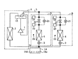
図3において、1は圧縮機、2は室外側熱交換器、3は絞り装置、4は室内側熱交換器であり、これらは環状配置に連通して主冷媒回路を形成している。そして、圧縮機1、室外側熱交換器2等により熱源機Aが構成され、絞り装置3、室内側熱交換器4等により室内機Bが構成される。5は冷媒配管であり、熱源機Aと1台ないし複数台の室内機Bとを連通している。熱源機Aは、上記のほかに、弁流路の切替えにより冷媒回路における冷媒の流れ方向を切替える第1四方弁15を備えている。
室内機Bは、上記のほかに、室内側熱交換器4のガス冷媒側の冷媒回路に設けられてガス冷媒を加圧し単方向に流通させるガスポンプ等の冷媒加圧手段16、冷媒加圧手段16と並列に冷媒回路に配備されて冷媒加圧手段16の未使用時に低圧損経路を形成する第1バイパス手段18、弁流路の切替えにより冷媒回路における冷媒流れ方向を双方向に切替えて流通させる第2四方弁17を備えている。冷媒加圧手段16と第2四方弁17は、第1四方弁15と室内側熱交換器4の間の冷媒回路に配備されている。冷媒加圧手段16の吐出側は第2四方弁17の高圧側入口17aに接続されている。冷媒加圧手段16の吸入側は第2四方弁17の低圧側出口17bに接続されている。室内機Bには、さらに、冷媒加圧手段16の室内側熱交換器4側の冷媒圧力に対応した圧力相当値を検出する第1圧力検出手段19、冷媒加圧手段16の熱源機A側の冷媒圧力に対応した圧力相当値を検出する第2圧力検出手段20、および、室内環境温度の目標温度を設定するための室内環境温度設定手段(図示せず。以下同じ)がそれぞれ配備されている。
【0017】
このように構成したことで、室内機Bにおける冷媒の流れ方向に応じて第2四方弁17の流路を切替え制御することにより、冷媒加圧手段16を常に加圧方向で働かせることができる。また、冷媒加圧手段16が不要な場合には、第1バイパス手段18を全開とすることで、圧力損失なしに、従来どおりの室内機Bとして動作させることができる。
【0018】
次に、制御動作について図4に基づいて説明する。
図4(a)は冷房運転の場合を示している。図において、制御装置14の第2制御手段14bは、各々の室内機Bにおける室内環境温度設定手段の設定温度に基づく目標圧力値または実際の室内環境温度に基づく目標圧力値に向けて、第1圧力検出手段19の検出圧力を近づけるように、冷媒加圧手段16の加圧制御量を変化させる。
このように構成したことで、熱源機Aにおける圧縮機1の吸入圧力に対応した冷媒飽和温度よりも低い蒸発温度を室内機B毎に実現でき、高い蒸発温度で良い室内機Bに合わせた熱源機Aの動作により、その室内機Bでの冷え過ぎに起因するサーモ発停頻度の増大、室内デフロスト運転頻度の増大を抑制することができる。
【0019】
図4(b)は暖房運転の場合を示している。図において、制御装置14の第2制御手段14bは、各々の室内機Bにおける室内環境温度設定手段の設定温度値に基づく目標圧力値または実際の室内環境温度に基づく目標圧力値に向けて、第1圧力検出手段19の検出圧力を近づけるように、冷媒加圧手段16の加圧制御量を変化させる。
このように構成したことで、熱源機Aにおける圧縮機1の吐出圧力に対応した冷媒飽和温度よりも高い凝縮温度を室内機B毎に実現でき、低い蒸発温度で良い室内機Bに合わせた熱源機Aの動作により、その室内機Bでの暖め過ぎに起因するサーモ発停頻度の増大を抑制することができる。
【0020】
次の制御動作につき、図5に基づいて説明する。
図5(a)は冷房(冷凍)運転の場合を示す。図において、制御装置14の第3制御手段14cは、熱源機Aの圧縮機吸入圧力の目標値に各々の室内機Bに接続される冷媒配管5での圧力損失相当分を加えた目標圧力値に向けて、第2圧力検出手段20の検出圧力を近づけるように、冷媒加圧手段16の加圧制御量を変化させる。
このように構成したことで、熱源機Aにおける圧縮機吸入圧力が低下して適正運転範囲を逸脱したり、冷媒回路の冷媒循環量が低下したり、あるいは、熱源機A側から逆算して室内機Bでの蒸発圧力が上昇し室内側熱交換器4での空気と冷媒の温度差が減少したりするといったことがなく、室内側熱交換器4で要求される蒸発能力の不足を抑制できる。
【0021】
図5(b)は暖房運転の場合を示す。図において、制御装置14の第3制御手段14cは、熱源機Aの圧縮機吐出圧力の目標値に各々の室内機Bに接続される冷媒配管5での圧力損失相当分を減算した目標圧力値に向けて、第2圧力検出手段20の検出圧力を近づけるように、冷媒加圧手段16の加圧制御量を変化させる。
このように構成したことで、熱源機Aにおける圧縮機吐出圧力の上昇や圧縮機吐出温度の上昇によって適正運転範囲を逸脱したり、あるいは、熱源機A側から逆算して室内機Bでの凝縮温度が低下して室内側熱交換器4での空気と冷媒の温度差が減少するといったことがなく、室内側熱交換器4で要求される凝縮能力が不足することを抑制できる。
【0022】
実施の形態3.
図6ないし図8を用いて、実施の形態3を説明する。
図6において、1は圧縮機、2は室外側熱交換器、3は絞り装置、4は室内側熱交換器であり、これらは環状配置に連通して主冷媒回路を形成している。そして、圧縮機1、室外側熱交換器2等より熱源機Aが構成され、絞り装置3、室内側熱交換器4等より室内機Bが構成される。5は冷媒配管であり、熱源機Aと1台ないし複数台の室内機Bとを連通している。熱源機Aは、上記のほかに、第1四方弁15を備えている。室内機Bは、上記のほかに、室内側熱交換器4のガス冷媒側における冷媒回路に配備されてガス冷媒を減圧する冷媒減圧手段21と、冷媒減圧手段21と並列に冷媒回路に配備されて冷媒減圧手段21の未使用時に低圧損経路を形成する第2バイパス手段22を備えている。さらに、室内機Bは、冷媒減圧手段21の室内側熱交換器4側における冷媒圧力に対応した圧力相当値を検出する第3圧力検出手段23、冷媒減圧手段21の熱源機A側の冷媒回路における冷媒圧力を検出する第2圧力検出手段24、室内環境温度を検出する室内環境温度検知手段25、室内環境温度設定手段を備えている。
【0023】
このように構成したことにより,室内機Bにおいて、冷媒減圧手段21が不要な場合に、第2バイパス手段22を全開とすることで、圧力損失なしに、従来どおりの室内機として動作することができる。
【0024】
次に、制御動作に付き、図7に基づいて説明する。
図7(a)は冷房運転の場合を示している。図において、制御装置14の第4制御手段14dは、各々の室内機Bにおける室内環境温度設定手段の設定温度に基づく目標圧力値または実際の室内環境温度に基づく目標圧力値に向けて、第3圧力検出手段23の検出圧力を近づけるように、冷媒減圧手段21の減圧制御量を変化させる。
このように構成したことで、熱源機Aにおける圧縮機1の吸入圧力に対応した冷媒飽和温度よりも高い蒸発温度を各々の室内機B毎に実現でき、低い蒸発温度の室内機Bに合わせた熱源機Aの動作により、高い蒸発温度で良い室内機Bにおける冷え過ぎに起因したサーモ発停頻度の増大や室内デフロスト運転頻度の増大を抑制できる。
【0025】
図7(b)は暖房運転の場合を示す。図において、制御装置14の第4制御手段14dは、各々の室内機Bにおける室内環境温度設定手段の設定温度に基づく目標圧力値または実際の室内環境温度に基づく目標圧力値に向けて、第3圧力検出手段23の検出圧力を近づけるように、冷媒減圧手段21の減圧制御量を変化させる。
このように構成したことで、熱源機Aにおける圧縮機吐出圧力に対応した冷媒飽和温度よりも低い凝縮圧力を各々の室内機B毎に実現でき、高い蒸発温度の室内機Bに合わせた熱源機Aの動作により、低い凝縮温度で良い室内機Bにおける暖め過ぎに起因するサーモ発停頻度の増大を抑制できる。
【0026】
次の制御動作に付き、図8に基づいて説明する。
図8は冷房(冷凍)運転の場合を示す。図において、各々の室内機Bにおける室内環境温度設定手段の設定値と室内環境温度検知手段25の検出値との差が小さくなった場合に、制御装置14の第5制御手段14eは、室内機Bの蒸発能力を抑制するため、熱源機Aにおける圧縮機吸入圧力に対応する目標圧力値を低下させる。さらに、第5制御手段14eは第4圧力検出手段24の検出圧力をその目標値に近づけるように、冷媒減圧手段21の減圧制御量を変化させる。
このように構成したことで、熱源機Aにおける圧縮機1の吸入圧力が低下して冷媒回路の冷媒循環量が抑制される。これにより、冷凍能力を抑制することができる。そして、室内機Bでの冷え過ぎに起因するサーモ発停頻度の増大や、室内デフロスト運転頻度の増大を抑制できる。
【0027】
【発明の効果】
本発明は、室内側熱交換器のガス冷媒側に冷媒加圧手段を設けたことにより、接続配管での圧損等による室内側熱交換器で要求される凝縮能力や蒸発能力が不足することを抑制できる。そのうえ、複数台の室内機で要求される室内側熱交換器の凝縮温度または蒸発温度が異なる場合でも、目標温度を最高の凝縮温度や最低の蒸発温度に設定したことによる暖め過ぎや冷え過ぎ、あるいはそれらに伴うサーモ発停頻度の増加やデフロスト運転頻度の増加等による室内温度変化の増大を抑制することができる。
【図面の簡単な説明】
【図1】 本発明の実施の形態1に係る冷凍サイクル装置の冷媒回路を示す構成図である。
【図2】 実施の形態1の冷凍サイクル装置の動作を説明するためのものであって、(a)はガスバイパス手段を制御する場合のp−h線図、(b)は液バイパス手段を制御する場合のp−h線図、(c)は凝縮器熱交換量変化手段を制御する場合のp−h線図である。
【図3】 本発明の実施の形態2に係る冷凍サイクル装置の冷媒回路を示す構成図である。
【図4】 実施の形態2の冷凍サイクル装置の動作を説明するためのものであって、(a)は冷房運転時のp−h線図、(b)は暖房運転時のp−h線図である。
【図5】 実施の形態2の冷凍サイクル装置の別の動作を説明するためのものであって、(a)は冷房運転時のp−h線図、(b)は暖房運転時のp−h線図である。
【図6】 本発明の実施の形態3に係る冷凍サイクル装置の冷媒回路を示す構成図である。
【図7】 実施の形態3の冷凍サイクル装置の動作を説明するためのものであって、(a)は冷房運転時のp−h線図、(b)は暖房運転時のp−h線図である。
【図8】 実施の形態3の冷凍サイクル装置における冷房運転時の別の動作を説明するためのp−h線図である。
【図9】 従来例の冷媒回路を示す構成図である。
【符号の説明】
1 圧縮機、2 室外側熱交換器(凝縮器)、3 絞り装置、4 室内側熱交換器(蒸発器)、5 冷媒配管、6 ファン、7 ガスバイパス手段、8 液バイパス手段、9 圧縮機吐出圧力検出手段、10 圧縮機吸入圧力検出手段、11 圧縮機吐出温度検知手段、12 圧縮機吸入温度検知手段、13 凝縮器出口温度検知手段、14 制御装置、14a 第1制御手段、14b 第2制御手段、14c 第3制御手段、14d 第4制御手段、14e 第5制御手段、15 第1四方弁、16 冷媒加圧手段、17 第2四方弁、17a 高圧側入口、17b 低圧側出口、18 第1バイパス手段、19 第1圧力検出手段、20 第2圧力検出手段、21 冷媒減圧手段、22 第2バイパス手段、23 第3圧力検出手段、24 第4圧力検出手段、25 室内環境温度検知手段、A熱源機、B 室内機。[0001]
BACKGROUND OF THE INVENTION
The present invention relates to a refrigeration cycle apparatus used for a refrigerator or an air conditioner, and particularly relates to protection of a compressor and ensuring of an appropriate refrigerant temperature in each indoor unit.
[0002]
[Prior art]
A conventional refrigeration cycle apparatus is generally configured as shown in FIG. In the figure, 1 is a compressor, 2 is a condenser, 3 is a throttling device, and 4 is an evaporator, which communicate with an annular arrangement to form a main refrigerant circuit. And the heat source machine A is comprised by the
In addition to the above, the heat source machine A is provided with actuators such as a
[0003]
[Problems to be solved by the invention]
Since the conventional refrigeration cycle apparatus is configured as described above, there are the following problems.
In particular, in the above-described refrigeration cycle apparatus in which the heat source unit A, the
Moreover, the condensation capacity or the evaporation capacity required for the
Alternatively, when the condensation temperatures or evaporation temperatures required by the plurality of
In addition, simple refrigeration capacity control means has been demanded instead of complicated refrigeration capacity control by capacity control using an inverter or the like.
[0004]
[Means for Solving the Problems]
The refrigeration cycle apparatus according to the present invention includes a refrigerant pipe that connects a heat source device that connects a compressor, an outdoor heat exchanger, and the like, and a plurality of indoor units that are connected to a throttle means, an indoor heat exchanger, and the like. An evaporating temperature equal to or lower than the refrigerant saturation temperature corresponding to the suction pressure of the compressor by providing a refrigerant pressurizing unit that pressurizes the gas refrigerant in the refrigerant circuit on the gas refrigerant side of the indoor heat exchanger. The evaporation temperature of the indoor side heat exchanger required by the plurality of indoor units is made different.
[0005]
Further, the refrigeration cycle apparatus according to the present invention is a refrigerant comprising a heat source device connected to a compressor, an outdoor heat exchanger, etc., and a plurality of indoor units connected to a throttle means, an indoor heat exchanger, etc. The refrigerant circuit is connected by piping, and the refrigerant circuit on the gas refrigerant side of the indoor heat exchanger is provided with a refrigerant pressurizing means for pressurizing the gas refrigerant, so that the refrigerant saturation temperature or higher corresponding to the discharge pressure of the compressor is exceeded. The condensation temperature is realized, and the condensation temperatures of the indoor heat exchangers required for the plurality of indoor units are made different.
[0006]
Further, in parallel with the refrigerant pressurizing means, a first bypass means for forming a low pressure loss path when the refrigerant pressurizing means is not used is provided.
[0007]
In addition, a refrigerant pressurizing means that pressurizes the refrigerant and circulates in one direction and a second four-way valve are arranged between the first four-way valve provided on the discharge side of the compressor and the indoor heat exchanger, The discharge side of the refrigerant pressurizing means is connected to the high pressure side inlet of the second four-way valve, the suction side of the refrigerant pressurizing means is connected to the low pressure side outlet of the second four-way valve, and the second four-way valve In this configuration, the refrigerant is switched in both directions by switching the flow path.
[0010]
DETAILED DESCRIPTION OF THE INVENTION
1 is a configuration diagram illustrating a refrigerant circuit of a refrigeration cycle apparatus according to
The heat source machine A includes a compressor discharge pressure detecting means 9 for detecting the refrigerant discharge pressure on the discharge side of the
[0011]
Here, the linkage control by the
That is, the condenser outlet temperature detecting means 13, the compressor discharge pressure detecting means 9 and the
[0012]
Further, changes on the Mollier diagram of the refrigeration cycle due to the operation of each actuator are as shown in FIG. 2 depending on the operation state and the control amount. In the operation of the gas bypass means 7, as shown in FIG. 5A, the valve opening direction operation is controlled in the direction of decreasing the compressor discharge temperature, decreasing the condenser outlet subcool, and increasing the compressor suction superheat. The In the operation of the liquid bypass means 8, as shown in FIG. 5B, the valve discharge direction operation is controlled in the direction of the compressor discharge temperature decrease, the condensation outlet subcool increase, and the compressor suction superheat decrease. The In the operation of the
As described above, all of the above three parameters vary depending on the control operation of each actuator. Therefore, according to the conventional idea of associating one actuator with one parameter, there is a possibility that the control variable vibrates such that the control variable does not converge toward the target value and swings. Therefore, the following formula is introduced to realize linkage control based on the following formula.
[0013]
[Expression 1]
Here, a to i in the equation are functions obtained in advance through experiments or the like.
Further, by defining a maximum value as the target value-detection value, a rapid change in the control amount is suppressed, and the control according to the above equation is periodically repeated. Further, the target value has an allowable range to suppress the vibration of the control operation.
[0015]
In this way, the first control means 14a of the
In addition, simple refrigeration capacity control such as gas bypass and liquid bypass can be realized instead of complicated refrigeration capacity control by capacity control of an inverter or the like.
Although the detected pressure of the compressor discharge pressure detecting means 9 is used for the control here, it goes without saying that the same control can be performed even if the high-pressure refrigerant saturation temperature detected at the intermediate portion of the
[0016]
The second embodiment will be described with reference to FIGS.
In FIG. 3, 1 is a compressor, 2 is an outdoor heat exchanger, 3 is an expansion device, 4 is an indoor heat exchanger, and these communicate with an annular arrangement to form a main refrigerant circuit. And the heat source machine A is comprised by the
In addition to the above, the indoor unit B is provided in the refrigerant circuit on the gas refrigerant side of the
[0017]
With this configuration, the refrigerant pressurizing means 16 can always be operated in the pressurizing direction by switching and controlling the flow path of the second four-way valve 17 according to the flow direction of the refrigerant in the indoor unit B. When the refrigerant pressurizing means 16 is not necessary, the first bypass means 18 is fully opened, so that it can be operated as a conventional indoor unit B without pressure loss.
[0018]
Next, the control operation will be described with reference to FIG.
FIG. 4A shows the case of the cooling operation. In the figure, the second control means 14b of the
With such a configuration, an evaporation temperature lower than the refrigerant saturation temperature corresponding to the suction pressure of the
[0019]
FIG. 4B shows the case of heating operation. In the figure, the second control means 14b of the
By comprising in this way, the condensation temperature higher than the refrigerant | coolant saturation temperature corresponding to the discharge pressure of the
[0020]
The next control operation will be described with reference to FIG.
FIG. 5A shows the case of cooling (freezing) operation. In the figure, the third control means 14c of the
With this configuration, the compressor suction pressure in the heat source unit A decreases and deviates from the proper operating range, or the refrigerant circulation amount in the refrigerant circuit decreases, or the room is calculated backward from the heat source unit A side. The evaporation pressure in the machine B does not increase and the temperature difference between the air and the refrigerant in the
[0021]
FIG. 5B shows the case of heating operation. In the figure, the third control means 14c of the
With this configuration, the proper operating range deviates due to an increase in the compressor discharge pressure and the compressor discharge temperature in the heat source unit A, or the condensation in the indoor unit B is calculated backward from the heat source unit A side. The temperature does not decrease and the temperature difference between the air and the refrigerant in the
[0022]
The third embodiment will be described with reference to FIGS.
In FIG. 6, 1 is a compressor, 2 is an outdoor heat exchanger, 3 is an expansion device, 4 is an indoor heat exchanger, and these communicate with an annular arrangement to form a main refrigerant circuit. And the heat source machine A is comprised from the
[0023]
With this configuration, in the indoor unit B, when the refrigerant decompression unit 21 is unnecessary, the
[0024]
Next, the control operation will be described with reference to FIG.
FIG. 7A shows the case of the cooling operation. In the figure, the fourth control means 14d of the
With this configuration, an evaporation temperature higher than the refrigerant saturation temperature corresponding to the suction pressure of the
[0025]
FIG. 7B shows the case of heating operation. In the figure, the fourth control means 14d of the
With this configuration, a condensing pressure lower than the refrigerant saturation temperature corresponding to the compressor discharge pressure in the heat source unit A can be realized for each indoor unit B, and the heat source unit adapted to the indoor unit B having a high evaporation temperature By the operation of A, it is possible to suppress an increase in the frequency of starting and stopping the thermo, which is caused by excessive warming in the indoor unit B that requires a low condensation temperature.
[0026]
The following control operation will be described with reference to FIG.
FIG. 8 shows the case of cooling (freezing) operation. In the figure, when the difference between the set value of the indoor environment temperature setting means and the detected value of the indoor environment temperature detection means 25 in each indoor unit B becomes small, the fifth control means 14e of the
With this configuration, the suction pressure of the
[0027]
【The invention's effect】
According to the present invention, by providing the refrigerant pressurizing means on the gas refrigerant side of the indoor heat exchanger, the condensing capacity and the evaporation capacity required for the indoor heat exchanger due to pressure loss in the connection pipe are insufficient. Can be suppressed. Moreover, even when the condensation temperature or evaporation temperature of the indoor heat exchanger required by multiple indoor units is different, the target temperature is set too high or too low due to the setting of the highest condensation temperature or lowest evaporation temperature. Or the increase of the indoor temperature change by the increase in the thermo start / stop frequency accompanying them, the increase in the defrost operation frequency, etc. can be suppressed.
[Brief description of the drawings]
FIG. 1 is a configuration diagram showing a refrigerant circuit of a refrigeration cycle apparatus according to
2A and 2B are diagrams for explaining the operation of the refrigeration cycle apparatus according to the first embodiment, wherein FIG. 2A is a ph diagram for controlling the gas bypass means, and FIG. 2B is a liquid bypass means. A ph diagram in the case of controlling, (c) is a ph diagram in the case of controlling the condenser heat exchange amount changing means.
FIG. 3 is a configuration diagram showing a refrigerant circuit of a refrigeration cycle apparatus according to
4A and 4B are diagrams for explaining the operation of the refrigeration cycle apparatus according to the second embodiment, wherein FIG. 4A is a ph diagram during cooling operation, and FIG. 4B is a ph diagram during heating operation. FIG.
5A and 5B are diagrams for explaining another operation of the refrigeration cycle apparatus according to the second embodiment, where FIG. 5A is a ph diagram during cooling operation, and FIG. 5B is p- during heating operation. FIG.
FIG. 6 is a configuration diagram showing a refrigerant circuit of a refrigeration cycle apparatus according to
7A and 7B are diagrams for explaining the operation of the refrigeration cycle apparatus according to
FIG. 8 is a ph diagram for explaining another operation during cooling operation in the refrigeration cycle apparatus of the third embodiment.
FIG. 9 is a configuration diagram showing a conventional refrigerant circuit.
[Explanation of symbols]
1 compressor, 2 outdoor heat exchanger (condenser), 3 expansion device, 4 indoor heat exchanger (evaporator), 5 refrigerant pipe, 6 fan, 7 gas bypass means, 8 liquid bypass means, 9 compressor Discharge pressure detection means, 10 Compressor suction pressure detection means, 11 Compressor discharge temperature detection means, 12 Compressor suction temperature detection means, 13 Condenser outlet temperature detection means, 14 Control device, 14a First control means, 14b Second Control means, 14c Third control means, 14d Fourth control means, 14e Fifth control means, 15 First four-way valve, 16 Refrigerant pressurizing means, 17 Second four-way valve, 17a High pressure side inlet, 17b Low pressure side outlet, 18 First bypass means, 19 First pressure detection means, 20 Second pressure detection means, 21 Refrigerant decompression means, 22 Second bypass means, 23 Third pressure detection means, 24 Fourth pressure detection means, 25 Indoor environment temperature detection Means, A heat source unit, B indoor unit.
Claims (4)
前記室内側熱交換器のガス冷媒側の冷媒回路に、ガス冷媒を加圧する冷媒加圧手段を設けることで、圧縮機の吸入圧力に対応した冷媒飽和温度以下の蒸発温度を実現させ、前記複数台の室内機で要求される室内側熱交換器の蒸発温度が異なるようにしたことを特徴とする冷凍サイクル装置。 In the refrigeration cycle apparatus in which a heat source device formed by connecting a compressor, an outdoor heat exchanger, and the like, and a plurality of indoor units formed by connecting a throttle means, an indoor heat exchanger, etc. are connected by a refrigerant pipe.
The refrigerant circuit on the gas refrigerant side of the indoor heat exchanger is provided with a refrigerant pressurizing unit that pressurizes the gas refrigerant, thereby realizing an evaporation temperature equal to or lower than a refrigerant saturation temperature corresponding to the suction pressure of the compressor, A refrigeration cycle apparatus characterized in that the evaporating temperature of the indoor side heat exchanger required for the indoor unit is different .
前記室内側熱交換器のガス冷媒側の冷媒回路に、ガス冷媒を加圧する冷媒加圧手段を設けることで、圧縮機の吐出圧力に対応した冷媒飽和温度以上の凝縮温度を実現させ、前記複数台の室内機で要求される室内側熱交換器の凝縮温度が異なるようにしたことを特徴とする冷凍サイクル装置。 In the refrigeration cycle apparatus in which a heat source device formed by connecting a compressor, an outdoor heat exchanger, and the like, and a plurality of indoor units formed by connecting a throttle means, an indoor heat exchanger, etc. are connected by a refrigerant pipe.
The refrigerant circuit on the gas refrigerant side of the indoor heat exchanger is provided with a refrigerant pressurizing unit that pressurizes the gas refrigerant, thereby realizing a condensation temperature equal to or higher than the refrigerant saturation temperature corresponding to the discharge pressure of the compressor. A refrigeration cycle apparatus characterized in that the condensation temperature of the indoor side heat exchanger required for the indoor unit of the base is different .
Priority Applications (1)
| Application Number | Priority Date | Filing Date | Title |
|---|---|---|---|
| JP2002209107A JP3705251B2 (en) | 2002-07-18 | 2002-07-18 | Refrigeration cycle equipment |
Applications Claiming Priority (1)
| Application Number | Priority Date | Filing Date | Title |
|---|---|---|---|
| JP2002209107A JP3705251B2 (en) | 2002-07-18 | 2002-07-18 | Refrigeration cycle equipment |
Related Parent Applications (1)
| Application Number | Title | Priority Date | Filing Date |
|---|---|---|---|
| JP2000092850A Division JP2001280669A (en) | 2000-03-30 | 2000-03-30 | Refrigerating cycle device |
Publications (3)
| Publication Number | Publication Date |
|---|---|
| JP2003042582A JP2003042582A (en) | 2003-02-13 |
| JP2003042582A5 JP2003042582A5 (en) | 2005-06-16 |
| JP3705251B2 true JP3705251B2 (en) | 2005-10-12 |
Family
ID=19195838
Family Applications (1)
| Application Number | Title | Priority Date | Filing Date |
|---|---|---|---|
| JP2002209107A Expired - Lifetime JP3705251B2 (en) | 2002-07-18 | 2002-07-18 | Refrigeration cycle equipment |
Country Status (1)
| Country | Link |
|---|---|
| JP (1) | JP3705251B2 (en) |
Families Citing this family (5)
| Publication number | Priority date | Publication date | Assignee | Title |
|---|---|---|---|---|
| JP4617958B2 (en) * | 2005-03-29 | 2011-01-26 | 三菱電機株式会社 | Air conditioner |
| CN105004110B (en) * | 2015-07-21 | 2018-01-30 | 三河同飞制冷股份有限公司 | Digit Control Machine Tool is with the frequency conversion temperature control system compensated with vapours |
| JP7183645B2 (en) * | 2018-09-12 | 2022-12-06 | 株式会社富士通ゼネラル | Heat pump hot water supply air conditioner |
| CN110131856B (en) * | 2019-05-20 | 2021-07-20 | 广东美的制冷设备有限公司 | Air conditioner and control method thereof |
| CN111578472B (en) * | 2020-05-29 | 2022-03-22 | 广东美的制冷设备有限公司 | Control method and device of air conditioner outdoor unit, air conditioner outdoor unit and air conditioner |
-
2002
- 2002-07-18 JP JP2002209107A patent/JP3705251B2/en not_active Expired - Lifetime
Also Published As
| Publication number | Publication date |
|---|---|
| JP2003042582A (en) | 2003-02-13 |
Similar Documents
| Publication | Publication Date | Title |
|---|---|---|
| US9506674B2 (en) | Air conditioner including a bypass pipeline for a defrosting operation | |
| JP3925545B2 (en) | Refrigeration equipment | |
| JP3972860B2 (en) | Refrigeration equipment | |
| JP4411870B2 (en) | Refrigeration equipment | |
| WO2006013938A1 (en) | Freezing apparatus | |
| JPH07234038A (en) | Multiroom type cooling-heating equipment and operating method thereof | |
| US11268737B2 (en) | Refrigeration cycle apparatus | |
| JP2001280669A (en) | Refrigerating cycle device | |
| JP6283815B2 (en) | Air conditioner | |
| JP6880204B2 (en) | Air conditioner | |
| EP2188576A1 (en) | Methods and systems for controlling integrated air conditioning systems | |
| JP2007292407A (en) | Air conditioner | |
| JP5375919B2 (en) | heat pump | |
| JP2007232265A (en) | Refrigeration unit | |
| JP2008025901A (en) | Air conditioner | |
| JP7063940B2 (en) | Refrigeration equipment | |
| JP2021103081A (en) | Heat source unit and refrigeration unit | |
| JP3705251B2 (en) | Refrigeration cycle equipment | |
| JP4720641B2 (en) | Refrigeration equipment | |
| JP5517891B2 (en) | Air conditioner | |
| WO2021010130A1 (en) | Refrigeration device | |
| JP2018096575A (en) | Freezer | |
| JPH0989416A (en) | Air conditioner | |
| JP2013092369A5 (en) | ||
| JP2002228284A (en) | Refrigerating machine |
Legal Events
| Date | Code | Title | Description |
|---|---|---|---|
| RD01 | Notification of change of attorney |
Free format text: JAPANESE INTERMEDIATE CODE: A7421 Effective date: 20040629 |
|
| A521 | Written amendment |
Free format text: JAPANESE INTERMEDIATE CODE: A523 Effective date: 20040908 |
|
| A131 | Notification of reasons for refusal |
Free format text: JAPANESE INTERMEDIATE CODE: A131 Effective date: 20050412 |
|
| A521 | Written amendment |
Free format text: JAPANESE INTERMEDIATE CODE: A523 Effective date: 20050610 |
|
| TRDD | Decision of grant or rejection written | ||
| A01 | Written decision to grant a patent or to grant a registration (utility model) |
Free format text: JAPANESE INTERMEDIATE CODE: A01 Effective date: 20050705 |
|
| A61 | First payment of annual fees (during grant procedure) |
Free format text: JAPANESE INTERMEDIATE CODE: A61 Effective date: 20050718 |
|
| R151 | Written notification of patent or utility model registration |
Ref document number: 3705251 Country of ref document: JP Free format text: JAPANESE INTERMEDIATE CODE: R151 |
|
| FPAY | Renewal fee payment (event date is renewal date of database) |
Free format text: PAYMENT UNTIL: 20080805 Year of fee payment: 3 |
|
| FPAY | Renewal fee payment (event date is renewal date of database) |
Free format text: PAYMENT UNTIL: 20090805 Year of fee payment: 4 |
|
| FPAY | Renewal fee payment (event date is renewal date of database) |
Free format text: PAYMENT UNTIL: 20090805 Year of fee payment: 4 |
|
| FPAY | Renewal fee payment (event date is renewal date of database) |
Free format text: PAYMENT UNTIL: 20100805 Year of fee payment: 5 |
|
| FPAY | Renewal fee payment (event date is renewal date of database) |
Free format text: PAYMENT UNTIL: 20110805 Year of fee payment: 6 |
|
| FPAY | Renewal fee payment (event date is renewal date of database) |
Free format text: PAYMENT UNTIL: 20110805 Year of fee payment: 6 |
|
| FPAY | Renewal fee payment (event date is renewal date of database) |
Free format text: PAYMENT UNTIL: 20120805 Year of fee payment: 7 |
|
| FPAY | Renewal fee payment (event date is renewal date of database) |
Free format text: PAYMENT UNTIL: 20120805 Year of fee payment: 7 |
|
| FPAY | Renewal fee payment (event date is renewal date of database) |
Free format text: PAYMENT UNTIL: 20130805 Year of fee payment: 8 |
|
| R250 | Receipt of annual fees |
Free format text: JAPANESE INTERMEDIATE CODE: R250 |
|
| R250 | Receipt of annual fees |
Free format text: JAPANESE INTERMEDIATE CODE: R250 |
|
| R250 | Receipt of annual fees |
Free format text: JAPANESE INTERMEDIATE CODE: R250 |
|
| R250 | Receipt of annual fees |
Free format text: JAPANESE INTERMEDIATE CODE: R250 |
|
| R250 | Receipt of annual fees |
Free format text: JAPANESE INTERMEDIATE CODE: R250 |
|
| EXPY | Cancellation because of completion of term |