JP3697488B2 - Digital camera - Google Patents
Digital camera Download PDFInfo
- Publication number
- JP3697488B2 JP3697488B2 JP2000048887A JP2000048887A JP3697488B2 JP 3697488 B2 JP3697488 B2 JP 3697488B2 JP 2000048887 A JP2000048887 A JP 2000048887A JP 2000048887 A JP2000048887 A JP 2000048887A JP 3697488 B2 JP3697488 B2 JP 3697488B2
- Authority
- JP
- Japan
- Prior art keywords
- program
- recording medium
- digital camera
- alternative
- rewritten
- Prior art date
- Legal status (The legal status is an assumption and is not a legal conclusion. Google has not performed a legal analysis and makes no representation as to the accuracy of the status listed.)
- Expired - Fee Related
Links
Images


Description
【0001】
【発明の属する技術分野】
本発明は撮影した画像を着脱可能な記録媒体に記録するデジタルカメラに関し、より詳しくは、自己が記憶しているプログラムに従って動作する記録媒体を使用するデジタルカメラに関する。
【0002】
【従来の技術】
デジタルカメラは、画像を略一定の周期で繰り返し撮影し、その間に使用者より与えられる記録指示に応じて、撮影した画像を着脱可能な記録媒体に記録する。記録媒体に記録された画像は、後にパーソナルコンピュータ等の他の機器で利用されるほか、使用者の確認に供するために、デジタルカメラによって読み出されて表示部に表示される。
【0003】
着脱可能な記録媒体は、データの書き込みおよび読み出しをデジタルカメラが直接行うものと、コントローラを備えて、コントローラがデータの書き込みおよび読み出しを行うものとに大別される。前者は、アドレスの管理等を含む記録媒体の制御全体をデジタルカメラが行う必要があるため、デジタルカメラが備えるべきプログラムが複雑になる。これに対し、後者は、動作の制御を記録媒体自体が行うため、デジタルカメラが記録媒体に関して備えるべきプログラムは、データの転送に関するもののみでよく、きわめて簡単である。このような点より、今日では、多くのデジタルカメラが後者の記録媒体すなわち自己の動作を自己が制御する記録媒体を使用している。
【0004】
動作制御を自己が行う記録媒体は、制御を司るコントローラおよび画像を記録するための不揮発性の記憶領域に加えて、コントローラが使用する制御プログラムを記憶した不揮発性の記憶領域を備えている。このような記録媒体としては、画像記録用にフラッシュメモリ等の半導体メモリを備え、外形をカード状としたものが従来より多用されており、最近では、画像記録用にハードディスクを備え、高度に小型化を図って外形をカード状としたものも使用されるようになってきた。これらカード状の記録媒体は、構成の差異にかかわらず、メモリカードと総称される。
【0005】
制御プログラム記憶用の領域は、一般に、画像記憶用の領域とは別に、専用の半導体メモリに設けられている。この半導体メモリとしては、従来より、マスクROM等の読み出しのみ可能なものが使用されてきたが、近年では、フラッシュメモリのように書き換え可能なものも使用されるようになっている。
【0006】
制御プログラムは、記録媒体のメーカーによって作成されて半導体メモリに書き込まれるが、通常、汎用性を有するように、すなわち種々のデジタルカメラで使用し得るように、基本的な規格に従って作成される。特に、使用の可否を決定づけるデータの転送方法としてはI/OモードまたはtrueIDEモードが設けられており、どのデジタルカメラも、データの転送をこれらの基本的な規格に則った方法で行う限り、装着可能なあらゆる記録媒体を使用することができる。
【0007】
【発明が解決しようとする課題】
ところが、汎用性を有するプログラムによる制御は、個々のデジタルカメラにとって最も効率のよい制御であるとは限らず、むしろ、書き込みや読み出しに関するデジタルカメラの性能を十分に生かし得ないことの方が多い。この不都合を避けるために、記録媒体の制御プログラムを特定のデジタルカメラに対して最適化することも行われている。そのような特定のデジタルカメラ専用の制御プログラムも、記録媒体のメーカーによって作成されて、記録媒体の製造時に書き込まれる。
【0008】
制御プログラム記憶用の領域として書き換え可能な半導体メモリを使用すると、制御プログラムごとにメモリを備えておく必要がなく、同一の半導体メモリに異なる制御プログラムを記憶させることができる。したがって、制御プログラム記憶用に書き換え可能な半導体メモリを使用する記録媒体が増加していくと予想される。
【0009】
特定のデジタルカメラに対して最適化した専用の制御プログラムは、種類の異なる他のデジタルカメラでは使用できない場合もある。このため、特定のデジタルカメラ専用の制御プログラムを記録媒体に記憶させる場合でも、汎用性のある制御プログラムも記憶させて、その記録媒体を他のデジタルカメラで使用することができるようにしている。
【0010】
しかしながら、記録媒体が特定のデジタルカメラ専用の制御プログラムを記憶していることは、種類の異なる他のデジタルカメラにとっては無意味であり、汎用性のある制御プログラムのみを記憶している場合と同様に、デジタルカメラの性能を十分に発揮させることはできない。たとえ、デジタルカメラごとに専用の制御プログラムを開発しても、また、その制御プログラムを書き換え可能な半導体メモリに記憶させても、特定のデジタルカメラ以外では、その制御プログラムを備えた記録媒体に特別な有用性はない。
【0011】
本発明は、このような問題点に鑑みてなされたもので、着脱可能な記録媒体の制御動作を最適化して、画像の記録に関する自己の性能を十分に発揮することが可能なデジタルカメラを提供することを目的とする。
【0012】
【課題を解決するための手段】
上記目的を達成するために、本発明では、着脱可能な記録媒体であって当該記録媒体自体が記憶している制御用のプログラムに従って動作するものを画像の記録に使用するデジタルカメラにおいて、書き換え可能な領域に制御用のプログラムを記憶している記録媒体を対象として、制御用の代替プログラムを記憶しておき、記憶している代替プログラムに適合する記録媒体を装着したときに、装着した記録媒体のプログラムを代替プログラムで書き換えるものとする。
【0013】
デジタルカメラの性能に応じて代替プログラムを最適化しておき、その代替プログラムで動作し得る記録媒体を装着したときに、記録媒体のプログラムを代替プログラムで書き換えることで、その記録媒体を使用する際にデジタルカメラの性能を最大限に発揮させることが可能になる。例えば、I/Oモード、trueIDEモード等の基本的な規格の転送方法とは別に、高速の転送方法をデジタルカメラにもたせる場合、記録媒体のプログラムがその転送方法に対応していなくても、その転送方法を記した代替プログラムで書き換えることで、記録媒体との間のデータ転送を高速で行うことができるようになる。代替プログラムは、例えば、デジタルカメラのメーカーが、製造時に記憶させておく。
【0014】
ここで、使用者からの指示を受けたときに限り、記録媒体のプログラムを代替プログラムで書き換えるようにすることができる。このようにすると、記録媒体をこのデジタルカメラまたは同種のデジタルカメラのみで使用し得るものとするか、種類の異なるデジタルカメラと共用し得るようにするかを、使用者が選択することが可能になる。
【0015】
記録媒体のプログラムを代替プログラムで書き換えるときに、代替プログラムで書き換える前のプログラムをその記録媒体の別の領域に記憶させるようにするとよい。記録媒体のプログラムを代替プログラムで書き換えた後で、元のプログラムに戻すことが可能になる。
【0016】
記録媒体のプログラムを代替プログラムで書き換えたときに、プログラムを代替プログラムで書き換えたことを示す書換済コードをその記録媒体に記憶させておき、記録媒体を装着したときに、その記録媒体のプログラムが代替プログラムで書き換えられたものであるか否かを書換済コードにより判別するようにしてもよい。このようにすると、記録媒体のプログラムを書き換えるという処理を記録媒体を装着するごとに行う必要がなくなる。また、書き換え済みのプログラムを同一プログラムで書き換えるという無駄を避けることができる。
【0017】
複数の代替プログラムを記憶しておくとともに、各代替プログラムに識別コードを付与しておき、記録媒体のプログラムを代替プログラムで書き換えたときに、その代替プログラムの識別コードをその記録媒体に記憶させるようにしてもよい。種類の異なる記録媒体ごとに最適の代替プログラムを用意しておくことで、どの種類の記録媒体を使用するときでもデジタルカメラの性能を十分に発揮させることができる上、代替プログラムの識別コードを記録媒体に記憶させることで、プログラム書き換え済みの記録媒体を装着したときに、その記録媒体がどのプログラムに従って動作するかを容易に判別することが可能になる。
【0018】
【発明の実施の形態】
以下、本発明のデジタルカメラの一実施形態について図面を参照しながら説明する。図1〜図4に本実施形態のデジタルカメラ1の外観を示し、図5にその回路構成を示す。図1はデジタルカメラ1の正面図、図2は背面図、図3は側面図、図4は底面図である。
【0019】
デジタルカメラ1は、略直方体状の本体部2と撮像部3(図1〜4において太線で示す)より成る。撮像部3は本体部2の側面に取り付けられており、その前面に撮影レンズ301を有する。撮影レンズ301はマクロ機能つきのズームレンズであり、口径固定の絞りを備えている。撮像部3の内部の撮影レンズ301後方には、撮像素子である電荷結合素子(CCD)303が配置されている(図5参照)。CCD303は、赤色(R)光、緑色(G)光および青色(B)光に対して選択的に感応する3種の画素を2次元に交互に配列して成り、カラーエリアセンサとして構成されている。
【0020】
撮像部3の内部には、CCD303が出力するアナログ信号を処理する信号処理回路313、CCD303の光電変換の開始や蓄積した電荷の出力等の動作のタイミングを指示する信号を生成してCCD303に与えるタイミングジェネレータ314、撮影レンズ301の焦点距離を変えるズームモータ306、および撮影レンズ301の焦点を変えるフォーカスモータ307が備えられている。撮像部3には、また、フラッシュ撮影において自動調光制御をするための調光回路304および調光センサ305、撮影対象までの距離を検出するAFセンサ308、ならびに光学ファインダ31も備えられている。
【0021】
デジタルカメラ1は非撮影時に撮影レンズ301の大部分を撮像部3に収容し得るように構成されており、撮影レンズ301は、撮影時に設定される撮影位置と非撮影時に設定される収容位置とをとる。ズームモータ306は、撮影レンズ301の撮影位置と収容位置間の移動にも用いられる。また、撮像部3には、撮影レンズ301が撮影位置と収容位置のいずれにあるかを検出するためのレンズセンサ309が設けられている。
【0022】
本体部2の前面にはグリップ部4とフラッシュ部5が設けられており、本体部2の上面にはシャッターボタン9が設けられている。シャッターボタン9は半押しされると信号S1を発し、全押しされるとさらに信号S2を発する。デジタルカメラ1は、撮影レンズ301の焦点を撮影対象に対して自動的に合わせる自動焦点調節(AF)機能と、撮影対象の明るさに応じてCCD303の露光を自動的に調節する自動露光調節(AE)機能とを備えており、信号S1はAF制御とAE制御の開始を指示する。信号S2は、記録用の画像の撮影と撮影した記録用画像を表す画像データの記録を指示する。
【0023】
図2に示すように、本体部2の背面には、透過型の液晶表示装置(LCD)10、押しボタン式の6つのスイッチ11、電源スイッチ12および4接点スイッチ13、スライド式のスイッチ14、ならびに2つの発光ダイオード15a、15bが設けられている。LCD10は、撮影した画像や使用者へのメッセージを表示する。スイッチ11はデジタルカメラ1の動作に関する種々の設定に用いられ、電源スイッチ12は電源から各部への電力供給の開始と停止の指示に用いられる。
【0024】
4接点スイッチ13は単一の操作部材と4つの接点より成り、4つのスイッチ13a〜13dを構成する。スイッチ13a、13bは撮影レンズ301の焦点距離の設定すなわちズーミングの指示に用いられ、スイッチ13c、13dはAE制御におけるCCD303の露光補正の指示に用いられる。
【0025】
デジタルカメラ1は、撮影モード、再生モードおよびメニューモードを有しており、スイッチ14はこれらのモードの設定に用いられる。撮影モードは、CCD303によって画像を撮影して、撮影した画像を表す画像データを生成するモードである。撮影および画像データの生成は略一定の周期(例えば1/30秒)で繰り返し行われ、シャッターボタン9の操作により信号S2が発せられると、それに応じて記録用の画像が撮影されて、その画像を表す画像データが記録媒体に記録される。撮影モードにおいては、次々と撮影される画像をLCD10に直ちに表示して、ライブビューを提供することもできる。このとき、LCD10は電子ビューファインダとして機能する。
【0026】
再生モードは記録媒体に記録している画像データを読み出して、その画像をLCD10に表示するモードである。また、メニューモードは、LCD10に案内メッセージを表示し、スイッチ11の操作に応じて動作に関する設定を行うモードである。
【0027】
発光ダイオード15aは電源から各部への電力供給が行われている間点灯し、発光ダイオード15bは記録媒体の入出力が行われている間点灯する。発光ダイオード15aは電源電圧の低下を使用者に知らせるためにも用いられる。
【0028】
撮像部3の背面には、2つの押しボタン式スイッチ16a、16bが設けられている。スイッチ16aは、撮影モードにおいてLCD10にライブビューを表示するか否かの指示に用いられ、スイッチ16aが操作されるごとにライブビュー表示のオン/オフが切り替わる。専ら光学ファインダ31を用いて撮影をする場合、LCD10の表示をオフにすることにより、電力消費を抑えることができる。再生モードおよびメニューモードにおける再生画像や案内メッセージの表示は、スイッチ16aの操作にかかわらず行われる。スイッチ16bはマクロ撮影をするか否かの指示に用いられる。
【0029】
デジタルカメラ1では、電源として、直列接続した4本の単三型乾電池Eを使用する。また、画像データを記録する記録媒体として、着脱可能なメモリカード8を使用する。メモリカード8は2枚装着可能である。メモリカード8およびそれらの動作制御については後に詳述する。図4に示すように、本体部2には、電池Eを収納する電池室18と、2つのカードスロット17a、17bを有しメモリカード8を収納するカード室17が設けられており、本体部2の底面には電池室18とカード室17を開閉するクラムシェルタイプの蓋19が備えられている。
【0030】
カードスロット17aには、メモリカードに代えて、USBカードや音声カードを装着することも可能である。蓋19にはUSBカードの端子部分を露出させるための開口19aが設けられており、USBカードの端子にケーブル接続することにより、デジタルカメラ1を外部機器に直接接続することができる。
【0031】
図3に示すように、本体部2の側面にはDC入力端子20が設けられており、デジタルカメラ1は、内蔵の電池Eのほか、端子20を介して外部から与えられる電力によっても動作する。
【0032】
デジタルカメラ1の回路構成について、図5を参照して説明する。撮像部3に設けられた信号処理回路313は、相関二重サンプリング(CDS)回路および自動ゲイン制御(AGC)回路より成る。CDS回路はCCD303が出力するアナログ信号のノイズを低減させ、AGC回路は、そのゲインによってCDS回路からの全ての信号のレベルを調整する。なお、CDS回路のゲインは以下に述べる全体制御部によって変えられる。
【0033】
本体部2は、デジタルカメラ1の全体を制御する全体制御部211を備えている。全体制御部211は、その制御プログラムや制御パラメータを記したROM211a、一時的な記憶に使用するRAM211b、および記録媒体であるメモリカード8の制御プログラムを記憶したROM211cを備えており、また、使用者によって操作される操作部250に接続されている。操作部250は、前述のシャッターボタン9、スイッチ14等の諸操作部材を含み、使用者による操作を全体制御部211に伝達する。
【0034】
本体部2は、信号処理回路313より与えられるCCD303の出力信号を処理して画像データを生成するために、A/Dコンバータ205、黒レベル補正回路206、ホワイトバランス(WB)回路207、γ補正回路208、および画像メモリ209を備えている。A/Dコンバータ205は、信号処理回路313からのアナログ信号を10ビットのデジタル信号に変換し、黒レベル補正回路206は、デジタル化された信号の黒レベルを基準のレベルに合わせる。
【0035】
WB回路207は、次に行うγ補正の後に適正なホワイトバランスが得られるように、全体制御部211から供給されるレベル変換テーブルを用いて、R、G、Bの各色成分の信号のレベルを個別に変換する。なお、全体制御部211は、レベル変換テーブルの各色成分の変換係数(特性の傾き)を、撮影した画像ごとに設定する。γ補正回路208は、表示に適するように、WB回路207からの信号に非線形化処理を施す。
【0036】
信号処理回路313からγ補正回路208までの処理により、CCD303によって撮影された画像を表す画像データが生成される。画像メモリ209は、こうして生成された画像データを1フレーム分記憶する。画像メモリ209はCCD303の画素数に相当する記憶容量を有しており、各画素の出力から生成した信号をその画素に対応する位置に記憶する。なお、黒レベル補正回路206からγ補正回路208までの各回路の処理結果は、実際には全体制御部211のRAM211bを介して次の回路に提供されるが、図5においては、処理の流れを明らかにするために、黒レベル補正回路206から画像メモリ209までを破線の矢印で接続して表している。
【0037】
本体部2には、LCD10に画像を表示する際にバッファメモリとして使用するVRAM210、LCD10のバックライト光源10a、およびメモリカード8への画像データの書き込みやメモリカード8からの画像データの読み出しを行うカードインターフェース(I/F)212も備えられている。VRAM210はLCD10の画素数に相当する記憶容量を有しており、全体制御部は211は、ライブビューや再生画像を表示するときは、画像メモリ209やメモリカード8から読み出した画像データの中から所定の画素間隔で信号を抽出し、それらの信号をVRAM210に書き込む。
【0038】
本体部2には、このほか、タイミング制御回路202、2つのモータ駆動回路216、217、リアルタイムクロック(RTC)219、フラッシュ制御回路220、給電回路218、および電圧検出回路213も備えられている。タイミング制御回路202は、動作周期の最小単位である基準クロックを生成するとともに、全体制御部211からの指示に応じて、制御用のクロックをタイミングジェネレータ314やA/Dコンバータ205に供給する。
【0039】
モータ駆動回路216、217はそれぞれ、全体制御部211からの指示に応じて、ズームモータ306、フォーカスモータ307を駆動する。RTC219は撮影の日時を管理するためのもので、電池Eとは別の電源(不図示)からの電力により、常時動作する。
【0040】
フラッシュ制御回路220は、全体制御部211からの指示に応じて、フラッシュ部5の発光やその準備を制御する。デジタルカメラ1では、フラッシュ撮影において自動調光制御を行うようにしており、全体制御部211は、フラッシュ制御回路220に発光を指示すると同時に調光センサ305による受光を開始させ、調光センサ305が所定量の光を受けたことを示す信号を調光回路304から与えられると同時に、フラッシュ制御回路220に発光の停止を指示する。
【0041】
給電回路218は、DC入力端子20を介して外部から供給される電力を検出し、外部からの電力供給があるときはその電力を、外部からの電力供給がないときは電池Eの電力を、CCD303、カードスロット17a、17b等の各部に供給する。給電回路218から各部への電力供給は全体制御部211により制御される。
【0042】
電圧検出回路213は、給電回路218が供給する電力の電圧を検出し、その電圧が所定値よりも低いときには、その旨を全体制御部211に伝える。これに応じて、全体制御部211は発光ダイオード15aを点滅させ、電源電圧が低下していることを使用者に知らせる。
【0043】
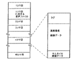
撮影モードにおいて信号S2により記録用画像の撮影が指示されると、全体制御部211は、直ちにAE制御等の撮影準備を行って、CCD303に記録用の画像を撮影させる。そして、撮影した記録用画像の画像データを画像メモリ209から読み出し、タグ情報を生成して、両者をカードI/F212に与えてメモリカード8に記録させる。その際、全体制御部211は、JPEG方式に従って画像データの圧縮を行う。また、全体制御部211は、画像データから所定の画素間隔で信号を抽出して別の画像データを生成し、これもメモリカード8に記録させる。この画像データは、撮影した高解像度の画像の数分の1の大きさのサムネイル画像を表す。タグ情報には、フレーム番号や撮影日時のほか、露光等の撮影条件に関する情報が含まれる。
【0044】
メモリカード8に記録するデータの構造を図6に模式的に示す。1フレームの画像情報は、タグ情報、圧縮された1600×1200画素の高解像度画像データ、および80×60画素のサムネイル画像データより成り、約1MBのデータ量を有する。メモリカード8に記録し得る画像のフレーム数は、当然、そのメモリカード8の記録容量に依存する。なお、音声カードを装着しているときは、フレームごとに音声ファイルも記録することが可能であり、タグに音声ファイルへのリンクに関する情報が記される。
【0045】
前述のように、デジタルカメラ1は2つのカードスロット17a、17bを備えており、2枚のメモリカード8を同時に装着することができる。カードスロット17a、17bに装着し得るメモリカード8の種類は1つに限られず、例えば、フラッシュメモリを内蔵した半導体メモリカードやハードディスクカードを、カードスロット17a、17bの各々に装着することが可能である。また、カードスロット17a、17bに種類の異なるメモリカードを同時に装着することもできる。
【0046】
撮影レンズ301に固定絞りを備えたデジタルカメラ1では、AE制御をCCD303の光電変換時間(電子シャッター速度)の調節により行う。AE制御は、周知のAPEXシステムに基づいて、全体制御部211が行う。AE制御に必要な撮影対象の明るさは、生成した画像データより求める。すなわち、画像データのうち、CCD303の所定範囲(例えば中央部)に対応する画素の信号強度の総和を撮影対象の明るさとする。
【0047】
AE制御は、前述のように、信号S1に応じてAF制御と共に開始するが、信号S2が発せられるまでは撮影対象の明るさの検出のみを行っておき、信号S2により記録用画像の撮影が指示された時に初めて、電子シャッター速度の調節を行う。その間、電子シャッター速度は一定にしておく。これにより、画像データの生成処理を一定周期で行うことが可能になり、全体制御部211の制御処理が複雑になるのを避けることができる。
【0048】
撮影対象が暗く、検出した明るさから算出した電子シャッター速度が手ぶれを起こす可能性のある速度になるときは、電子シャッター速度を手ぶれ限界速度に設定するとともに、信号処理回路313に含まれるAGC回路のゲインを上昇させて、CCD303が露光不足になるのを補償する。これにより、撮影対象がある程度暗い場合でも、撮影対象を良好な明るさで表す画像を提供することができる。なお、ゲインを最大にしても露光不足を補うことができないほど撮影対象が暗いときには、手ぶれ限界速度で撮影してゲインを最大に設定するとともに、露光不足になる可能性があることを警告して、フラッシュ撮影を行う等の適切な対策を講じることを使用者に促す。
【0049】
デジタルカメラ1が記録媒体として使用するメモリカード8は、自己が記憶している制御用のプログラムに従って動作するものである。メモリカード8の構成を図7に模式的に示す。メモリカード8は、画像を記録するための記憶領域8a、自己の属性と制御用のプログラムを記憶する記憶領域8b、およびCPUを含むコントローラ8cを備えている。
【0050】
記憶領域8aは、フラッシュメモリまたはハードディスクより成り、電力供給を受けないときでも記憶内容を保持する不揮発性であるとともに、書き換え可能でもある。コントローラ8cは、記憶領域に8bに記憶している制御用のプログラムに従って、記憶領域8aへのデータの書き込み、記憶領域8aからのデータの読み出し、およびデジタルカメラ1との間のデータの転送を行う。
【0051】
記憶領域8bはフラッシュメモリより成り、不揮発性である上、書き換え可能である。制御用のプログラムは、メモリカード8のメーカーによって作成されて、メモリカード8の製造時に記憶領域8bに書き込まれる。前述のように、メーカーによって作成された制御用のプログラムは、汎用性をもたせるために基本的な規格に従っており、例えば、転送方法としてI/OモードまたはtrueIDEモードを有する。
【0052】
デジタルカメラ1は、データの転送方法として、I/OモードとtrueIDEモードに加えて、ブロックモードを有している。ブロックモードでは、一度に大量のデータを転送することが可能であり、I/OモードやtrueIDEモードよりもデータ転送の速度が数倍も高い。
【0053】
デジタルカメラ1は、このブロックモードでのデータ転送を可能とすることを含め、データの記録に関する処理を最も効率よく行うために、メモリカード8の記憶領域8bの制御用のプログラムを、自己が記憶している代替プログラムで書き換える。代替プログラムは、デジタルカメラ1のメーカーにより、デジタルカメラ1のデータ転送に関する性能とメモリカード8の構成を考慮して作成され、製造時に全体制御部211のROM211cに書き込まれている。
【0054】
デジタルカメラ1は複数種類のメモリカード8を装着することができるが、装着可能な全てのメモリカードに対して代替プログラムが用意されており、ROM211cはこれら全ての代替プログラムを記憶している。なお、ROM211cはフラッシュメモリより成り、メーカーは、デジタルカメラ1の性能向上や新たなメモリカードの開発に応じて、ROM211cの代替プログラムを随時更新することができる。デジタルカメラ1の使用者も、新たに開発されたメモリカードを最も効率よく使用し得るように、メーカーに依頼して、ROM211cに代替プログラムを追加することができる。
【0055】
ROM211cの記憶内容の例を図8に模式的に示す。この例は、3種類のメモリカードのために、3つの代替プログラムSP1〜SP3を記憶している状態を表している。各プログラムに対応して、メモリカードのメーカー名および型番が記憶されており、また、プログラムが採用している転送方法およびプログラムを特定するための識別コードも記憶されている。
【0056】
どのメモリカードにも記憶領域8bにメーカー名と型番が記されており、デジタルカメラ1は、メモリカード装着時にこれらを読み取って、ROM211cに記憶しているメーカー名および型番と一致しているか否かを調べ、そのメモリカードが自己の記憶している代替プログラムに適合する種類であるか否かを判別する。そして、適合するメモリカードであれば、その旨をLCD10に表示し、使用者からの指示に応じてメモリカードの記憶領域8bのプログラムを代替プログラムで書き換える。代替プログラムに適合しないメモリカードの場合や、適合していても使用者からの書き換え指示がない場合には、プログラムの書き換えは行わない。
【0057】
メモリカード8の記憶領域8bの記憶内容の例を図9に模式的に示す。図9において、(a)はプログラムを書き換える前の状態を表しており、(b)はプログラムを書き換えた後の状態を表している。デジタルカメラ1は、メモリカードのプログラムの書き換えに際して、転送方法も書き換え、さらに、代替プログラムの識別コード、自己のメーカー名および製造番号を、記憶領域8bの所定部位に記憶させる。そして、メモリカード装着時にはこれらも読み取る。
【0058】
代替プログラムの識別コードをメモリカードに記憶させることにより、メモリカードを装着したときに、そのプログラムが代替プログラムであるか否か、および代替プログラムであればどの代替プログラムであるかを容易に知ることができる。また、デジタルカメラ1のメーカー名と製造番号をメモリカードに記憶させることにより、メモリカードが記憶している代替プログラムを自己が書き換えたものであるか、他のデジタルカメラが書き換えたものであるかを知ることができる。これにより、識別コードが同じで他のデジタルカメラが書き換えた使用できない代替プログラムを、使用可能と誤認するのを避けることができる。
【0059】
メモリカード8に記憶させる識別コード、メーカー名および製造番号は、そのメモリカードのプログラムが書き換え済みであることを示すコードとして利用されることになる。なお、デジタルカメラ1のメーカー名および製造番号は全体制御部211のROM211aに記憶されている。
【0060】
デジタルカメラ1は、メモリカード8のプログラムを書き換えるときは、書き換え前に、記憶領域8bに記憶されているプログラムおよび転送方法を読み出して、自己のRAM211bに記憶する。これにより、記憶領域8bのプログラムを代替プログラムで書き換えている途中で不測の事故が生じたときでも、メモリカードを確実に元の状態に復帰させることができる。
【0061】
また、プログラムの書き換えを終了したときは、記憶領域8bから読み出してRAM211bに記憶したプログラムおよび転送方法を、メモリカード8の画像用の記憶領域8aの所定部位に記憶させる。これにより、使用者は、メモリカード8のプログラムを代替プログラムで書き換えた後でも、任意に元のプログラムに戻すことができる。記憶領域8bのプログラムおよび転送方法を記憶するための記憶領域8aの部位をバックアップ領域8a’という(図7)。
【0062】
デジタルカメラ1におけるメモリカード8のプログラムの書き換えに関する処理の流れを図10のフローチャートに示す。この処理は、全体制御部211が行う処理を記したプログラムの1つのサブルーチンであり、メモリカード8を装着したことを検出したときに開始される。メモリカード8が装着されたか否かは、カードスロット17a、17bに設けられている接点からの信号で判定する。
【0063】
まず、装着されたメモリカード8の記憶領域8bからメモリカードの属性に関する情報を読み取って、読み取った情報をRAM211bに記憶する(ステップ#5)。次いで、読み取った情報に含まれるメモリカードのメーカー名および型番をROM211cに記憶している代替プログラムのものと比較して、メモリカードがいずれかの代替プログラムに適合するか否かを判定する(#10)。メモリカードがどの代替プログラムにも適合しないときは、読み取った情報に含まれる転送方法をメモリカードとの間のデータの転送方法として設定して(#50)、メインルーチンに戻る。
【0064】
装着したメモリカードがいずれかの代替プログラムに適合するときは、読み取った情報に代替プログラムの識別コードが含まれているか否かを判定する(#15)。識別コードが含まれていないときは、メモリカードのプログラムを代替プログラムで書き換えることが可能であることをLCD10に表示する(#20)。使用者は、書き換えを希望するときは、この表示に応えて指示を与える。前述のスイッチ11のうちの所定のものが書き換えの指示に割り当てられており、所定時間(例えば10秒)内にそのスイッチを操作することにより、書き換えの指示を与えることができる。次いで、書き換えの指示があったか否かを判定し(#25)、指示がなければ、読み取った情報に含まれる転送方法をデータの転送方法として設定する(#50)。
【0065】
書き換えの指示があったときは、メモリカードの記憶領域8bから制御用のプログラムを読み出して、読み出したプログラムをRAM211bに記憶する(#30)。そして、記憶領域8bのプログラムを代替プログラムで書き換えるとともに(#35)、書き換えた代替プログラムの識別コード、転送方法、デジタルカメラのメーカー名および製造番号を記憶領域8bに記憶させる。書き換え終了後、記憶領域8bから読み出してRAM211bに記憶したプログラムを、メモリカードの記憶領域8a内のバックアップ領域8a’に記憶させる(#40)。そして、書き換えた代替プログラムの転送方法をメモリカードとの間のデータの転送方法として設定し(#45)、メインルーチンに戻る。
【0066】
ステップ#15の判定で、読み取った情報に代替プログラムの識別コードが含まれているときは、読み取った情報に含まれるデジタルカメラのメーカー名および製造番号が自己のものに一致するか否かを判定する(#55)。メーカー名および製造番号が一致しないときは、メモリカードの記憶領域のプログラムが他のデジタルカメラによって書き換えられた代替プログラムであるから、そのメモリカードを使用することができないことをLCD10に表示して(#90)、メインルーチンに戻る。
【0067】
メーカー名および製造番号が自己のものに一致するときは、プログラムの復元、すなわち、メモリカードの記録領域8bのプログラムを、代替プログラムで書き換える前の元のプログラムに戻すことが可能であることをLCD10に表示する(#60)。使用者は、プログラムの復元を希望するときは、この表示に応えて指示を与える。書き換えの指定に割り当てられたスイッチ11は復元の指示にも割り当てられており、前述の所定時間内にこのスイッチを操作することにより、復元の指示を与えることができる。次いで、復元の指示があったか否かを判定し(#65)、指示がなければ、読み取った情報に含まれる転送方法をデータの転送方法として設定する(#50)。
【0068】
復元の指示があったときは、メモリカードのバックアップ領域8a’から元のプログラムを読み出して、読み出したプログラムをRAM211bに記憶する(#70)。そして、記憶領域8bのプログラムをRAM211bに記憶した元のプログラムで書き換えるとともに(#75)、元のプログラムの転送方法を記憶領域8bに記憶させ、代替プログラムの識別コード、デジタルカメラのメーカー名および製造番号を記憶領域8bから消去する。書き換え終了後、メモリカードのバックアップ領域8a’のプログラムを消去して、この領域を画像の記録のために開放する(#80)。そして、書き換えた元のプログラムの転送方法をデータの転送方法として設定して(#85)、メインルーチンに戻る。
【0069】
なお、上記の処理では、読み取った情報に含まれる製造番号が自己の製造番号に一致しないときには、そのメモリカード8を使用しないようにしているが(ステップ#55、90)、これは、他のデジタルカメラで使用したメモリカードを使用者が誤ってデジタルカメラ1に装着した場合でも、記録されている画像を失うことがないようにするための予防策である。製造番号が一致しないときには、その旨を表示して警告し、その後にステップ#65に進むようにしてもよい。
【0070】
以上述べたように、デジタルカメラ1では、メモリカード8の制御用のプログラムを最適化した代替プログラムで書き換えるため、メモリカードへのデータの書き込みおよびメモリカードからのデータの読み出しを効率よく行うことができる。特に、データ転送を高速で行うことが可能な転送方法を代替プログラムに採用しているため、画像の記録や再生に要する時間が大幅に短縮されて、記録用画像の撮影に続いて次の画像を速やかに撮影することや、再生表示する画像を速やかに切り替えることが可能になる。しかも、プログラムの復元も可能であるから、メモリカードを他のデジタルカメラと共用することも容易であり、種類の異なるデジタルカメラを所持する使用者にとってきわめて使い勝手がよいといえる。
【0071】
なお、ここでは記録媒体として半導体メモリカードおよびハードディスクカーに代表されるメモリカードを使用する例を示したが、本発明は、記録媒体の制御プログラムが書き換え可能な領域に記されている限り、記録媒体の外観や記憶領域の具体的な構成にかかわりなく、適用することができる。
【0072】
【発明の効果】
書き換え可能な領域に制御用のプログラムを記憶している記録媒体を対象として、制御用の代替プログラムを記憶しておき、記憶している代替プログラムに適合する記録媒体を装着したときに、装着した記録媒体のプログラムを代替プログラムで書き換えるようにした本発明のデジタルカメラでは、記録媒体を使用する際にデジタルカメラの性能を最大限に発揮させることが可能になり、撮影した画像の記録や、記録している画像の再生表示を速やかに行うことができる。
【0073】
使用者からの指示を受けたときに限り、記録媒体のプログラムを代替プログラムで書き換えるようにすることで、記録媒体をこのデジタルカメラまたは同種のデジタルカメラの専用とするか否かを、使用者が選択することが可能になる。したがって、何種類かのデジタルカメラを所持する使用者にとって、記録媒体を効率よく利用することができるようになる。
【0074】
記録媒体のプログラムを代替プログラムで書き換えるときに、代替プログラムで書き換える前のプログラムをその記録媒体の別の領域に記憶させるようにすることで、記録媒体のプログラムを代替プログラムで書き換えた後に、元のプログラムに戻すことも可能になる。これによっても、記録媒体を効率的に利用することができる。
【0075】
記録媒体のプログラムを代替プログラムで書き換えたときに、プログラムを代替プログラムで書き換えたことを示す書換済コードをその記録媒体に記憶させておき、記録媒体を装着したときに、その記録媒体のプログラムが代替プログラムで書き換えられたものであるか否かを書換済コードにより判別するようにすると、記録媒体のプログラムを書き換えるという処理を記録媒体を装着するごとに行う必要がなくなる。また、書き換え済みのプログラムを同一プログラムで書き換えるという無駄を避けることができる。したがって、画像の記録に関する性能を十分に発揮し得るだけでなく、そのための準備も能率よく行うことが可能なデジタルカメラとなる。
【0076】
複数の代替プログラムを記憶しておくとともに、各代替プログラムに識別コードを付与しておき、記録媒体のプログラムを代替プログラムで書き換えたときに、その代替プログラムの識別コードをその記録媒体に記憶させるようにすると、複数種類の記録媒体のうちのどれを使用するときでも、自己の性能を十分に発揮し得るデジタルカメラとなる。また、記録媒体を装着したときに、その記録媒体がどのプログラムに従って動作するかを識別コードにより容易に判別することができるから、画像の記録や読み出しを速やかに開始することが可能になる。
【図面の簡単な説明】
【図1】 本発明の一実施形態のデジタルカメラの正面図。
【図2】 上記デジタルカメラの背面図。
【図3】 上記デジタルカメラの側面図。
【図4】 上記デジタルカメラの底面図。
【図5】 上記デジタルカメラの回路構成を示すブロック図。
【図6】 上記デジタルカメラのメモリカードに記録するデータの構造を模式的に示す図。
【図7】 上記デジタルカメラが使用するメモリカードの構成を模式的に示す図。
【図8】 上記デジタルカメラが記憶している代替プログラムおよび代替プログラムに関する情報の例を模式的に示す図。
【図9】 メモリカードが記憶している属性および制御プログラムの例を模式的に示す図。
【図10】 上記デジタルカメラにおけるメモリカードのプログラムの書き換えに関する処理の流れを示すフローチャート。
【符号の説明】
1 デジタルカメラ
2 本体部
3 撮像部
8 メモリカード
8a 画像用記憶領域
8a’ バックアップ領域
8b 属性、プログラム用記憶領域
8c コントローラ
9 シャッターボタン
10 LCD
17a、17b カードスロット
31 光学ファインダ
205 A/Dコンバータ
206 黒レベル補正回路
207 WB回路
208 γ補正回路
209 画像メモリ
210 VRAM
211 全体制御部
211a ROM
211b RAM
211c ROM
212 カードインターフェース
250 操作部
301 撮影レンズ
303 CCD
313 信号処理回路
314 タイミングジェネレータ[0001]
BACKGROUND OF THE INVENTION
The present invention relates to a digital camera that records captured images on a detachable recording medium, and more particularly to a digital camera that uses a recording medium that operates according to a program stored therein.
[0002]
[Prior art]
The digital camera repeatedly captures images at a substantially constant period, and records the captured images on a removable recording medium according to a recording instruction given by the user during that time. The image recorded on the recording medium is used later by other devices such as a personal computer, and is read out by the digital camera and displayed on the display unit for confirmation by the user.
[0003]
Removable recording media are roughly classified into those in which a digital camera directly writes and reads data and those in which a controller is provided and the controller writes and reads data. In the former, since the digital camera needs to perform overall control of the recording medium including address management and the like, the program that the digital camera should have becomes complicated. On the other hand, since the recording medium itself controls the operation of the latter, the program that the digital camera should have regarding the recording medium need only be related to data transfer and is very simple. For this reason, many digital cameras today use the latter recording medium, that is, a recording medium in which the operation of itself is controlled.
[0004]
A recording medium that performs operation control by itself includes a non-volatile storage area that stores a control program used by the controller, in addition to a controller that controls the control and a non-volatile storage area for recording an image. As such a recording medium, a semiconductor memory such as a flash memory for image recording and a card-shaped outer shape have been used more frequently than before. Recently, a hard disk for image recording is provided, and it is highly compact. In order to achieve this, a card-shaped outer shape has come to be used. These card-shaped recording media are collectively referred to as memory cards regardless of the difference in configuration.
[0005]
The area for storing the control program is generally provided in a dedicated semiconductor memory separately from the area for storing the image. Conventionally, as the semiconductor memory, a readable memory such as a mask ROM has been used. However, recently, a rewritable memory such as a flash memory has been used.
[0006]
The control program is created by the manufacturer of the recording medium and written in the semiconductor memory. Usually, the control program is created in accordance with a basic standard so as to be versatile, that is, usable in various digital cameras. In particular, the I / O mode or true IDE mode is provided as a data transfer method that determines whether or not it can be used, and any digital camera can be installed as long as the data transfer is performed in accordance with these basic standards. Any possible recording medium can be used.
[0007]
[Problems to be solved by the invention]
However, control by a program having general versatility is not necessarily the most efficient control for each digital camera, but rather, the performance of the digital camera related to writing and reading cannot be fully utilized. In order to avoid this inconvenience, a recording medium control program is also optimized for a specific digital camera. A control program dedicated to such a specific digital camera is also created by the manufacturer of the recording medium and written when the recording medium is manufactured.
[0008]
When a rewritable semiconductor memory is used as a control program storage area, it is not necessary to provide a memory for each control program, and different control programs can be stored in the same semiconductor memory. Therefore, it is expected that the number of recording media using a rewritable semiconductor memory for storing control programs will increase.
[0009]
A dedicated control program optimized for a specific digital camera may not be used with other digital cameras of different types. Therefore, even when a control program dedicated to a specific digital camera is stored in a recording medium, a versatile control program is also stored so that the recording medium can be used in another digital camera.
[0010]
However, the fact that the recording medium stores a control program dedicated to a specific digital camera is meaningless for other types of digital cameras and is the same as when only a general-purpose control program is stored. In addition, the performance of digital cameras cannot be fully demonstrated. Even if a dedicated control program is developed for each digital camera, or the control program is stored in a rewritable semiconductor memory, a recording medium equipped with the control program is specially used except for a specific digital camera. There is no usefulness.
[0011]
The present invention has been made in view of such problems, and provides a digital camera capable of optimizing the control operation of a detachable recording medium and sufficiently exhibiting its own performance relating to image recording. The purpose is to do.
[0012]
[Means for Solving the Problems]
In order to achieve the above object, in the present invention, a rewritable recording medium that operates according to a control program stored in the recording medium itself can be rewritten in a digital camera that is used for image recording. When an alternative program for control is stored for a recording medium that stores a control program in a specific area, and a recording medium that conforms to the stored alternative program is installed, the installed recording medium The above program is rewritten with an alternative program.
[0013]
When an alternative program is optimized according to the performance of the digital camera and a recording medium that can operate with the alternative program is loaded, the program on the recording medium can be rewritten with the alternative program to use the recording medium. It is possible to maximize the performance of digital cameras. For example, in addition to the transfer method of basic standards such as I / O mode and true IDE mode, when a high-speed transfer method is given to a digital camera, even if the program of the recording medium does not support the transfer method, By rewriting with an alternative program describing the transfer method, data transfer to and from the recording medium can be performed at high speed. The alternative program is stored, for example, by the manufacturer of the digital camera at the time of manufacture.
[0014]
Here, only when an instruction from the user is received, the program of the recording medium can be rewritten with the alternative program. In this way, the user can select whether the recording medium can be used only with this digital camera or the same kind of digital camera or can be shared with different types of digital cameras. Become.
[0015]
When the program on the recording medium is rewritten with the alternative program, the program before being rewritten with the alternative program may be stored in another area of the recording medium. After rewriting the program on the recording medium with the alternative program, it is possible to return to the original program.
[0016]
When the program of the recording medium is rewritten with the alternative program, the rewritten code indicating that the program is rewritten with the alternative program is stored in the recording medium, and when the recording medium is loaded, the program of the recording medium is Whether or not the program has been rewritten by the alternative program may be determined based on the rewritten code. This eliminates the need to rewrite the recording medium program each time the recording medium is loaded. Further, it is possible to avoid waste of rewriting a rewritten program with the same program.
[0017]
A plurality of alternative programs are stored, an identification code is assigned to each alternative program, and when the program of the recording medium is rewritten with the alternative program, the identification code of the alternative program is stored in the recording medium It may be. By preparing an optimal alternative program for each type of recording medium, the performance of the digital camera can be fully demonstrated when using any type of recording medium, and an identification code for the alternative program is recorded. By storing the program in the medium, it is possible to easily determine which program the recording medium operates according to when the program-rewritten recording medium is loaded.
[0018]
DETAILED DESCRIPTION OF THE INVENTION
Hereinafter, an embodiment of a digital camera of the present invention will be described with reference to the drawings. 1 to 4 show the appearance of the
[0019]
The
[0020]
Inside the
[0021]
The
[0022]
A
[0023]
As shown in FIG. 2, on the back of the
[0024]
The 4-
[0025]
The
[0026]
The reproduction mode is a mode in which image data recorded on the recording medium is read and the image is displayed on the
[0027]
The
[0028]
Two push button switches 16 a and 16 b are provided on the back surface of the
[0029]
The
[0030]
In place of the memory card, a USB card or an audio card can be mounted in the
[0031]
As shown in FIG. 3, a
[0032]
The circuit configuration of the
[0033]
The
[0034]
The
[0035]
The
[0036]
By processing from the
[0037]
The
[0038]
In addition, the
[0039]
The
[0040]
The
[0041]
The
[0042]
The
[0043]
When shooting of a recording image is instructed by the signal S2 in the shooting mode, the
[0044]
The structure of data recorded on the
[0045]
As described above, the
[0046]
In the
[0047]
As described above, the AE control starts together with the AF control according to the signal S1, but only the brightness of the object to be imaged is detected until the signal S2 is generated, and the recording image is captured by the signal S2. The electronic shutter speed is adjusted only when instructed. Meanwhile, the electronic shutter speed is kept constant. As a result, the image data generation process can be performed at a constant cycle, and the control process of the
[0048]
When the object to be photographed is dark and the electronic shutter speed calculated from the detected brightness is a speed at which camera shake may occur, the electronic shutter speed is set to the camera shake limit speed and the AGC circuit included in the
[0049]
The
[0050]
The storage area 8a is composed of a flash memory or a hard disk, and is non-volatile that retains stored contents even when it is not supplied with power, and is also rewritable. The
[0051]
The storage area 8b is composed of a flash memory, and is nonvolatile and rewritable. The control program is created by the manufacturer of the
[0052]
The
[0053]
The
[0054]
Although the
[0055]
An example of the contents stored in the
[0056]
Whether or not each memory card has a manufacturer name and model number written in the storage area 8b, and the
[0057]
An example of the contents stored in the storage area 8b of the
[0058]
By storing the identification code of the alternative program in the memory card, it is easy to know whether the program is an alternative program and which alternative program if the memory card is installed. Can do. Also, by storing the manufacturer name and serial number of the
[0059]
The identification code, manufacturer name and serial number stored in the
[0060]
When the
[0061]
When the rewriting of the program is finished, the program read from the storage area 8b and stored in the
[0062]
A flow of processing relating to rewriting of the program of the
[0063]
First, information relating to the attribute of the memory card is read from the storage area 8b of the loaded
[0064]
When the installed memory card is compatible with any alternative program, it is determined whether or not the read information includes an identification code of the alternative program (# 15). When the identification code is not included, it is displayed on the
[0065]
When there is an instruction to rewrite, the control program is read from the storage area 8b of the memory card, and the read program is stored in the
[0066]
If the identification information of the alternative program is included in the read information in the determination of
[0067]
When the manufacturer name and serial number match those of the self, the
[0068]
When there is an instruction for restoration, the original program is read from the backup area 8a ′ of the memory card, and the read program is stored in the
[0069]
In the above processing, when the manufacturing number included in the read information does not match the own manufacturing number, the
[0070]
As described above, since the
[0071]
Although an example in which a memory card represented by a semiconductor memory card and a hard disk car is used as a recording medium is shown here, the present invention is not limited as long as the control program of the recording medium is written in a rewritable area. The present invention can be applied regardless of the appearance of the medium and the specific configuration of the storage area.
[0072]
【The invention's effect】
For a recording medium that stores a control program in a rewritable area, the control alternative program is stored, and it is installed when a recording medium that matches the stored alternative program is installed With the digital camera of the present invention in which the program of the recording medium is rewritten with an alternative program, it becomes possible to maximize the performance of the digital camera when using the recording medium. It is possible to promptly display and reproduce the image being played.
[0073]
Only when an instruction from the user is received, by rewriting the program of the recording medium with an alternative program, the user can determine whether the recording medium is dedicated to this digital camera or the same kind of digital camera. It becomes possible to select. Therefore, the recording medium can be efficiently used for a user who possesses several types of digital cameras.
[0074]
When rewriting a program on a recording medium with an alternative program, the program before rewriting with the alternative program is stored in another area of the recording medium. It is also possible to return to the program. This also makes it possible to efficiently use the recording medium.
[0075]
When the program of the recording medium is rewritten with the alternative program, the rewritten code indicating that the program is rewritten with the alternative program is stored in the recording medium, and when the recording medium is loaded, the program of the recording medium is If it is determined by the rewritten code whether or not the program has been rewritten by the alternative program, it is not necessary to perform the process of rewriting the program of the recording medium every time the recording medium is mounted. Further, it is possible to avoid waste of rewriting a rewritten program with the same program. Therefore, the digital camera can not only fully exhibit the performance related to image recording, but also can efficiently prepare for it.
[0076]
A plurality of alternative programs are stored, an identification code is assigned to each alternative program, and when the program of the recording medium is rewritten with the alternative program, the identification code of the alternative program is stored in the recording medium Then, when any one of a plurality of types of recording media is used, the digital camera can fully exhibit its performance. Further, when the recording medium is loaded, it is possible to easily determine which program the recording medium operates according to the identification code, so that it is possible to quickly start recording and reading an image.
[Brief description of the drawings]
FIG. 1 is a front view of a digital camera according to an embodiment of the present invention.
FIG. 2 is a rear view of the digital camera.
FIG. 3 is a side view of the digital camera.
FIG. 4 is a bottom view of the digital camera.
FIG. 5 is a block diagram showing a circuit configuration of the digital camera.
FIG. 6 is a diagram schematically showing the structure of data recorded on a memory card of the digital camera.
FIG. 7 is a diagram schematically showing a configuration of a memory card used by the digital camera.
FIG. 8 is a diagram schematically illustrating an example of an alternative program stored in the digital camera and information related to the alternative program.
FIG. 9 is a diagram schematically showing an example of attributes and control programs stored in a memory card.
FIG. 10 is a flowchart showing a flow of processing relating to rewriting of a program of a memory card in the digital camera.
[Explanation of symbols]
1 Digital camera
2 Body
3 Imaging unit
8 Memory card
8a Image storage area
8a 'Backup area
8b Attribute, program storage area
8c controller
9 Shutter button
10 LCD
17a, 17b Card slot
31 Optical viewfinder
205 A / D converter
206 Black level correction circuit
207 WB circuit
208 γ correction circuit
209 Image memory
210 VRAM
211 Overall control unit
211a ROM
211b RAM
211c ROM
212 Card interface
250 operation unit
301 Shooting lens
303 CCD
313 Signal processing circuit
314 Timing Generator
Claims (5)
書き換え可能な領域に制御用のプログラムを記憶している記録媒体を対象として、制御用の代替プログラムを記憶しておき、記憶している代替プログラムに適合する記録媒体を装着したときに、装着した記録媒体のプログラムを代替プログラムで書き換えることを特徴とするデジタルカメラ。In a digital camera that uses a detachable recording medium that operates according to a control program stored in the recording medium itself to record an image,
For a recording medium that stores a control program in a rewritable area, store an alternative program for control, and attach it when a recording medium that matches the stored alternative program is installed A digital camera characterized by rewriting a program on a recording medium with an alternative program.
Priority Applications (1)
| Application Number | Priority Date | Filing Date | Title |
|---|---|---|---|
| JP2000048887A JP3697488B2 (en) | 2000-02-21 | 2000-02-21 | Digital camera |
Applications Claiming Priority (1)
| Application Number | Priority Date | Filing Date | Title |
|---|---|---|---|
| JP2000048887A JP3697488B2 (en) | 2000-02-21 | 2000-02-21 | Digital camera |
Publications (2)
| Publication Number | Publication Date |
|---|---|
| JP2001238113A JP2001238113A (en) | 2001-08-31 |
| JP3697488B2 true JP3697488B2 (en) | 2005-09-21 |
Family
ID=18570910
Family Applications (1)
| Application Number | Title | Priority Date | Filing Date |
|---|---|---|---|
| JP2000048887A Expired - Fee Related JP3697488B2 (en) | 2000-02-21 | 2000-02-21 | Digital camera |
Country Status (1)
| Country | Link |
|---|---|
| JP (1) | JP3697488B2 (en) |
Families Citing this family (1)
| Publication number | Priority date | Publication date | Assignee | Title |
|---|---|---|---|---|
| JP2009094687A (en) * | 2007-10-05 | 2009-04-30 | Nikon Corp | Camera having projector |
-
2000
- 2000-02-21 JP JP2000048887A patent/JP3697488B2/en not_active Expired - Fee Related
Also Published As
| Publication number | Publication date |
|---|---|
| JP2001238113A (en) | 2001-08-31 |
Similar Documents
| Publication | Publication Date | Title |
|---|---|---|
| JP4277309B2 (en) | Digital camera | |
| JP2003224767A (en) | Imaging apparatus, method for determining main subject position and program | |
| JP2001245249A (en) | Digital camera | |
| JP2003087803A (en) | Image pickup device, signal processing method, program and storage medium | |
| JP2003052004A (en) | Imaging device, image reproducing device and method therefor, and program thereof | |
| US20040061789A1 (en) | Digital still camera | |
| JP4574087B2 (en) | Imaging apparatus, control method thereof, control program thereof, and storage medium | |
| JP3697488B2 (en) | Digital camera | |
| JP4298088B2 (en) | Imaging apparatus and control method thereof | |
| JPH1141511A (en) | Electronic camera | |
| JP2001352510A (en) | Digital camera | |
| JP4038720B2 (en) | Image recording device | |
| JP4019176B2 (en) | Image processing method and apparatus | |
| JPH11272634A (en) | Peripheral device of computer | |
| JP2001223977A (en) | Digital camera | |
| JP3478261B2 (en) | Information equipment | |
| JP2005311493A (en) | Camera | |
| JP4477214B2 (en) | Electronic camera | |
| JP3989657B2 (en) | camera | |
| JP4253132B2 (en) | Imaging device | |
| JP4991412B2 (en) | Imaging apparatus, image recording method, and program | |
| JP2007219822A (en) | Imaging apparatus | |
| JPH1042187A (en) | Digital camera and display method for digital camera | |
| JP4298491B2 (en) | Imaging device | |
| JP4338919B2 (en) | Imaging device and replacement unit |
Legal Events
| Date | Code | Title | Description |
|---|---|---|---|
| A977 | Report on retrieval |
Free format text: JAPANESE INTERMEDIATE CODE: A971007 Effective date: 20050516 |
|
| TRDD | Decision of grant or rejection written | ||
| A01 | Written decision to grant a patent or to grant a registration (utility model) |
Free format text: JAPANESE INTERMEDIATE CODE: A01 Effective date: 20050524 |
|
| A711 | Notification of change in applicant |
Free format text: JAPANESE INTERMEDIATE CODE: A712 Effective date: 20050603 |
|
| A61 | First payment of annual fees (during grant procedure) |
Free format text: JAPANESE INTERMEDIATE CODE: A61 Effective date: 20050603 |
|
| R150 | Certificate of patent or registration of utility model |
Free format text: JAPANESE INTERMEDIATE CODE: R150 |
|
| FPAY | Renewal fee payment (event date is renewal date of database) |
Free format text: PAYMENT UNTIL: 20080715 Year of fee payment: 3 |
|
| FPAY | Renewal fee payment (event date is renewal date of database) |
Free format text: PAYMENT UNTIL: 20090715 Year of fee payment: 4 |
|
| FPAY | Renewal fee payment (event date is renewal date of database) |
Free format text: PAYMENT UNTIL: 20090715 Year of fee payment: 4 |
|
| FPAY | Renewal fee payment (event date is renewal date of database) |
Free format text: PAYMENT UNTIL: 20100715 Year of fee payment: 5 |
|
| FPAY | Renewal fee payment (event date is renewal date of database) |
Free format text: PAYMENT UNTIL: 20100715 Year of fee payment: 5 |
|
| FPAY | Renewal fee payment (event date is renewal date of database) |
Free format text: PAYMENT UNTIL: 20110715 Year of fee payment: 6 |
|
| FPAY | Renewal fee payment (event date is renewal date of database) |
Free format text: PAYMENT UNTIL: 20120715 Year of fee payment: 7 |
|
| FPAY | Renewal fee payment (event date is renewal date of database) |
Free format text: PAYMENT UNTIL: 20130715 Year of fee payment: 8 |
|
| R250 | Receipt of annual fees |
Free format text: JAPANESE INTERMEDIATE CODE: R250 |
|
| R250 | Receipt of annual fees |
Free format text: JAPANESE INTERMEDIATE CODE: R250 |
|
| LAPS | Cancellation because of no payment of annual fees |