JP3684108B2 - Network device management apparatus and method - Google Patents
Network device management apparatus and method Download PDFInfo
- Publication number
- JP3684108B2 JP3684108B2 JP16556999A JP16556999A JP3684108B2 JP 3684108 B2 JP3684108 B2 JP 3684108B2 JP 16556999 A JP16556999 A JP 16556999A JP 16556999 A JP16556999 A JP 16556999A JP 3684108 B2 JP3684108 B2 JP 3684108B2
- Authority
- JP
- Japan
- Prior art keywords
- packet
- network
- network management
- address
- response
- Prior art date
- Legal status (The legal status is an assumption and is not a legal conclusion. Google has not performed a legal analysis and makes no representation as to the accuracy of the status listed.)
- Expired - Fee Related
Links
Images


Classifications
-
- H—ELECTRICITY
- H04—ELECTRIC COMMUNICATION TECHNIQUE
- H04L—TRANSMISSION OF DIGITAL INFORMATION, e.g. TELEGRAPHIC COMMUNICATION
- H04L41/00—Arrangements for maintenance, administration or management of data switching networks, e.g. of packet switching networks
- H04L41/02—Standardisation; Integration
- H04L41/0213—Standardised network management protocols, e.g. simple network management protocol [SNMP]
Description
【0001】
【発明の属する技術分野】
本発明は、例えばコンピュータネットワークに接続されたデバイス等を管理するためのネットワークデバイス管理装置及び方法に関する。
【0002】
【従来の技術】
近年、コンピュータを相互に接続したローカルエリアネットワーク(LAN)が普及しており、このようなローカルエリアネットワークは、ビルのフロアまたはビル全体、ビル群(構内)、地域、あるいはさらに大きいエリアにわたって構築することができる。このようなネットワークは更に相互接続され、世界的規模のネットワークにも接続することができる。このような相互接続されたそれぞれのLANは、多様なハードウェア相互接続技術といくつものネットワークプロトコルを持つことがある。
【0003】
他と切り離された簡単なLANは個々のユーザが管理することができる。すなわち、ユーザが機器を取り替えたり、ソフトウェアをインストールしたり、問題点を診断したりすることができる。
【0004】
しかし一方、規模の大きい複雑なLANや相互接続された大きなLANグループは「管理」を必要とする。「管理」とは、人間のネットワーク管理者とその管理者が使用するソフトウェアの両方による管理を意味する。本願においては、「管理」とはシステム全体を管理するためのソフトウェアによる管理を意味し、「ユーザ」とはネットワーク管理ソフトウェアを使用する人を意味するものとする。このユーザは、通常、システム管理責任者である。ユーザは、ネットワーク管理ソフトウェアを使うことによって、ネットワーク上で管理データを得て、このデータを変更することができる。
【0005】
大規模ネットワークシステムは、通常、機器の増設と除去、ソフトウェアの更新、及び問題の検出などを絶えず行うことが必要な動的システムである。一般に、様々な人が所有する、様々な業者から供給される様々なシステムが存在する。
【0006】
このような大規模ネットワークシステムを構成するネットワーク上のデバイスを管理するための方法として、これまでにいくつかの試みが数多くの標準機関でなされている。国際標準化機構(ISO)は開放型システム間相互接続(Open System Interconnection,OSI)モデルと呼ばれる汎用基準フレームワークを提供した。ネットワーク管理プロトコルのOSIモデルは、共通管理情報プロトコル(Comon Management Information Protocol,CMIP)と呼ばれる。CMIPはヨーロツパの共通ネットワーク管理プロトコルである。
【0007】
また近年では、より共通性の高いネットワーク管理プロトコルとして、簡易ネットワーク管理プロトコル(Simple Network Management Protocol,SNMP)と呼ばれるCMIPに関連する一変種のプロトコルがある。(「TCP/IP ネットワーク管理入門実用的な管理をめざして」M.T.ローズ=著/西田竹志=訳(株)トッパン発行1992年8月20日初版を参照。)
このSNMPネットワーク管理技術によれば、ネットワーク管理システムには、少なくとも1つのネットワーク管理ステーション(NMS)、各々がエージェントを含むいくつかの管理対象ノード、及び管理ステーションやエージェントが管理情報を交換するために使用するネットワーク管理プロトコルが含まれる。ユーザは、NMS上でネットワーク管理ソフトウェアを用いて管理対象ノード上のエージェントソフトウェアと通信することにより、ネットワーク上のデータを得、またデータを変更することができる。
【0008】
ここでエージェントとは、各々のターゲット装置についてのバックラウンドプロセスとして走るソフトウェアである。ユーザがネットワーク上の装置に対して管理データを要求すると、管理ソフトウェアはオブジェクト識別情報を管理パケットまたはフレームに入れてターゲットエージェントへ送り出す。エージェントは、そのオブジェクト識別情報を解釈して、そのオブジェクト識別情報に対応するデータを取り出し、そのデータをパケットに入れてユーザに送り返す。時には、データを取り出すために対応するプロセスが呼び出される場合もある。
【0009】
またエージェントは、自分の状態に関するデータをデータベースの形式で保持している。このデータベースのことを、MIB(Management Information Base)と呼ぶ。図4は、MIBの構造を示す概念図である。図4に示すように、MIBは木構造のデータ構造をしており、全てのノードが一意に番号付けされている。図4において、かっこ内に書かれている番号が、そのノードの識別子である。例えば、図4においてノード401の識別子は1である。ノード402の識別子は、ノード401の下の3なので、1・3と表記される。同様にして、ノード403の識別子は、1・3・6・1・2と表記される。このノードの識別子のことを、オブジェクト識別子(OBJECT IDENTIFIER)と呼ぶ。
【0010】
このMIBの構造は、管理情報構造(SMI:Structure of Management Information)と呼ばれ、RFC1155 Structure and Identificatlon of Management Information for TCP/IP-based Internetsで規定されている。
【0011】
図4には、標準として規定されているMIBのうち、一部のもののみを抜き出して記載してある。
【0012】
次に、SNMPプロトコルについて簡単に説明する。ネットワーク管理ユーティリティソフトウェアが動作しているPC(以下、マネージャと呼称する)とSNMPエージェントが動作している管理対象ネγトワークデバイス(以下、エージェントと呼称する)とは、SNMPプロトコルを用いて通信を行う。SNMPプロトコルには5種類のコマンドがあり、それぞれGet−request、Get−next−request、Get−response、Set−request、Trapと呼ばれる。これらのコマンドがマネージャとエージェントの間でやりとりされる様子を図8に示す。
【0013】
Get−requestおよびGet−next−requestは、マネージャがエージェントのMIBオブジェクトの値を取得するために、マネージャがエージェントに対して送出するコマンドである。このコマンドを受け取ったエージェントは、MIBの値をマネージャに通知するために、マネージャに対してGet−responseコマンドを送出する(801および802)。
【0014】
Set−requestは、マネージャがエージェントのMIBオブジェクトの値を設定するために、マネージャがエージェントに対して送出するコマンドである。このコマンドを受け取ったエージェントは、設定結果をマネージャに通知するために、マネージャに対してGet−responseコマンドを送出する(803)。
【0015】
Trapは、エージェントが自分自身の状態の変化をマネージャに対して通知するために、エージェントがマネージャに対して送出するコマンドである(804)。
【0016】
図7に、Trap以外のコマンド、即ちGet−request、Get−next−request、Get−responseおよびSet−requestのフォーマットを示す。
【0017】
700は、SNMPメッセージを示す。SNMPメッセージは、バージョン701、コミュニティ名702およびPDUと呼ばれる領域703からなる。PDU703を詳細に示したものが710である。PDU710は、PDUタイプ711、リクエストID712、エラーステータス713、エラーインデックス714およびMIB情報715からなる。PDUタイプ711には、コマンドを識別する値が格納される。即ちこのフィールドの値が0であるならばGet−request、1であるならばGet−next−request、2であるならばGet−response、3であるならばSet−requestと識別される。また、エラーステータス713には、エラー情報を示す値が格納される。エラーが無い場合には、このフィールドの値は0である。また、MIB情報715には、オブジェクトIDとその値が組みになって格納される。
【0018】
次に、管理が必要な大規模なネットワークについて説明する。
【0019】
図1は、プリンタをネットワークに接続するためのネットワークボード(NB)101を、開放型アーキテクチャを持つプリンター102へつなげた場合を示す図である。NB101はローカルエリアネットワーク(LAN)100へ、例えば、同軸コネクタをもつEthernetインターフェース10Base-2や、RJ−45を持つ10Base-T等のLANインターフェースを介してつながれている。
【0020】
PC103やPC104等の複数のパーソナルコンピューター(PC)もまた、100に接続されており、ネットワークオペレーティングシステムの制御の下、これらのPCはNB101と通信することができる。PCの一つ、例えばPC103を、ネットワーク管理部として使用するように指定することができる。PCに、PC104に接続されているプリンター105のようなプリンターを接続してもよい。
【0021】
また、LAN100にファイルサーバー106が接続されており、これは大容量(例えば100億バイト)のネットワークディスク107に記憶されたファイルへのアクセスを管理する。プリントサーバー108は、接続されたプリンター109a及び109b、又は遠隔地にあるプリンター105などのプリンターに印刷を行わせる。また他の図示しない周辺機器をLAN100に接続してもよい。
【0022】
更に詳しくは、図1に示すネットワークは、様々なネットワークメンバー間で効率良く通信を行うために、NovellやUNIXのソフトウェアなどのネットワークソフトウェアを使用することができる。どのネットワークソフトウェアを使用することも可能であるが、例えば、Novell社のNetWare(Novell社の商標。以下省略)ソフトウェアを使用することができる。このソフトウェアパッケージに関する詳細な説明は、NetWareパッケージに同梱されているオンラインドキュメンテーションを参照のこと。これは、Novell社からNetWareパッケージとともに購入可能である。
【0023】
図1の構成について簡潔に説明すると、ファイルサーバー106は、LANメンバー間でデータのファイルの受信や、記憶、キューイング、キャッシング、及び送信を行う、ファイル管理部としての役割を果たす。例えば、PC103及びPC104それぞれによって作られたデータファイルは、ファイルサーバー106へ送られ、ファイルサーバー106はこれらのデータファイルを順に並べ、そしてプリントサーバー108からのコマンドに従って、並べられたデータファイルをプリンター109aへ送信する。
【0024】
またPC103とPC104はそれぞれ、データファイルの生成や、生成したデータファイルのLAN100への送信や、また、LAN100からのファイルの受信や、更にそのようなファイルの表示及び/又は処理を行うことのできる、通常のPCで構成される。図1にパーソナルコンピューター機器が示されているが、ネットワークソフトウェアを実行するのに適切であるような、他のコンピューター機器を含んでもよい。例えば、UNIXのソフトウェアを使用している場合に、UNIXワークステーションをネットワークに含んでもよく、これらのワークステーションは、適切な状況下で、図示されているPCと共に使用することができる。
【0025】
通常、LAN100などのLANは、一つの建物内の一つの階又は連続した複数の階でのユーザーグループ等の、幾分ローカルなユーザーグループにサービスを提供する。例えば、ユーザーが他の建物や他県に居るなど、あるユーザーが他のユーザーから離れるに従って、ワイドエリアネットワーク(WAN)を作ってもよい。WANは、基本的には、いくつかのLANを高速度サービス総合デジタルネットワーク(ISDN)電話線等の高速度デジタルラインで接続して形成された集合体である。従って、図1に示すように、LAN100と、LAN110と、LAN120とは変調/復調(MODEM)/トランスポンダー130及びバックボーン140を介して接続されWANを形成する。これらの接続は、数本のバスによる単純な電気的接続である。それぞれのLANは専用のPCを含み、また、必ずしも必要なわけではないが、通常はファイルサーバー及びプリントサーバーを含む。
【0026】
従って図1に示すように、LAN110は、PC111と、PC112と、ファイルサーバー113と、ネットワークディスク114と、プリントサーバー115と、プリンター116及びプリンター117とを含む。対照的に、LAN120はPC121とPC122のみを含む。LAN100と、LAN110と、LAN120とに接続されている機器は、WAN接続を介して、他のLANの機器の機能にアクセスすることができる。
【0027】
エージェントの実装例として、プリンタをネットワークに接続するためのネットワークボード上にエージェントを実装することが考えられる。これにより、プリンタをネットワーク管理ソフトウェアによる管理の対象とすることができる。ユーザは、ネットワーク管理ソフトウェアを用いて制御対象のプリンタの情報を得、また状態を変更することができる。より具体的には、例えばプリンタの液晶ディスプレイに表示されている文字列を取得したり、デフォルトの給紙カセットを変更したりすることができる。以下、エージェントを実装したネットワークボード(NB)をプリンタに接続する実施形態について説明する。図2に示すように、好ましくは、NB101は、プリンター102の内部拡張I/Oスロットに内蔵されており、NB101は、下に示す処理及びデータ記憶機能を持つ「埋め込まれた」ネットワークノードとなる。このNB101の構成により、大きなマルチエリアWANネットワークを統括及び管理するための、特徴的な補助機能を持つという利点をもたらす。これらの補助機能は、例えば、ネットワーク上の遠隔地(ネットワーク統括者の事務所など)からのプリンター制御及び状態観察や、各印刷ジョブ後の次のユーザーのための保証初期環境を提供するためのプリンター構成の自動管理、及びプリンターの負荷量を特徴付け、あるいはトナーカートリッジの交換スケジュールを組むためにネットワークを通してアクセスできる、プリンターログ又は使用統計を含む。
【0028】
このNB設計において重要な要因は、共有メモリ等の両方向インターフェースを介して、NB101からプリンター制御状態にアクセスする機能である。共有メモリ以外に、SCSIインターフェース等のインターフェースを使用することもできる。これにより、多数の便利な補助機能のプログラムができるように、プリンター操作情報をNB101又は外部ネットワークノードへ送出することができる。印刷画像データ及び制御情報のブロックは、NB101上にあるマイクロプロセッサーによって構成され、共有メモリに記述され、そして、プリンター102によって読み込まれる。同様に、プリンター状態情報は、プリンター102から共有メモリへ送られ、そこからNBプロセッサーによって読み込まれる。
【0029】
図2は、NB101をプリンター102にインストールした状態を示す断面図である。図2に示すように、NB101はネットワーク接続の為のフェースプレート101bを設置した印刷回路ボード101aから構成されており、コネクタ170を介してプリンターインターフェースや−ド150に接続されている。プリンターインターフェースカード150は、プリンター102のプリンターエンジンを直接制御する。印刷データ及びプリンター状態コマンドは、NB101からコネクタ170を介して、プリンターインターフェースカード150へ入力され、また、プリンター状態情報はプリンターインターフェースカード150からやはりコネクター170を介して得られる。NB101はこの情報を、フェースプレート101bのネットワークコネクタを介して、LAN100上で通信する。同時に、プリンター102は、従来のシリアルポート102a及びパラレルポート102bから、印刷データを受信することもできる。
【0030】
図3は、NB101とプリンター102とLAN100との電気的接続を示すブロック図である。NB101は、LAN100へはLANインターフェースを介して、プリンター102へはプリンターインターフェースカード150を介して直接接続されている。NB101上にはNB101を制御するためのマイクロプロセッサー301と、マイクロプロセッサー301の動作プログラムを格納するためのROM303と、マイクロプロセッサー301がプログラムを実行する上でワークとして用いるためのRAM302と、NB101とプリンタインタフェースカード150とが相互にデータをやりとりするための共有メモリ200があり、内部バスを通じて相互に接続されている。NB101がSNMPのエージェントとして動作するためのプログラムはROM303に格納されている。マイクロプロセッサ301は、ROM303に格納されたプログラムに従って動作し、ワークエリアとしてRAM302を用いる。また、プリンターインターフェースカード150と相互に通信するためのバッファ領域として共有メモリ200を用いる。
【0031】
プリンターインタフェースカード150上のマイクロプロセッサー151はNB101とのデータのアクセスを、NB101に設置されている共有メモリ200を介して行う。プリンターインタフェースカード150上のマイクロプロセッサー151は、実際に印刷機構を動かすプリンターエンジン160とも通信する。
【0032】
一方、ネットワーク管理ソフトウェアが稼動するPC側について、以下で説明する。
【0033】
図5は、ネットワーク管理ソフトウェアが稼動可能なPCの構成を示すブロック図である。
【0034】
図5において、500は、ネットワーク管理ソフトウェアが稼動するPCであり、図1における103と同等である。PC500は、ROM502もしくはハードディスク(HD)511に記憶された、あるいはフロッピーディスクドライブ(FD)512より供給されるネットワーク管理プログラムを実行するCPU501を備え、システムバス504に接続される各デバイスを総括的に制御する。
【0035】
503はRAMで、CPU501の主メモリ、ワークエリア等として機能する。
【0036】
505はキーボードコントローラ(KBC)で、キーボード(KB)509や不図示のポインティングデバイス等からの指示入力を制御する。506はCRTコントローラ(CRTC)で、CRTディスプレイ(CRT)510の表示を制御する。507はディスクコントローラ(DKC)で、ブートプログラム、種々のアプリケーション、編集ファイル、ユーザファイルそしてネットワーク管理プログラム等を記憶するハードディスク(HD)511およびフロッピーディスクコントローラ(FD)512とのアクセスを制御する。508はネットワークインタフェースカード(NIC)で、LAN100を介して、エージェントあるいはネットワーク機器と双方向にデータをやりとりする。
【0037】
次に、従来例におけるネットワーク管理ソフトウェアの構成について説明する。
【0038】
従来例におけるネットワーク管理装置は、図5に示したようなネットワーク管理装置を実現可能なPCと同様の構成のPC上に実現される。ハードディスク(HD)511には、後述のすべての説明で動作主体となる本願に係るネットワーク管理ソフトウェアのプログラムが格納される。後述のすべての説明において、特に断りのない限り、実行の主体はハード上はCPU501である。一方、ソフトウェア上の制御の主体は、ハードディスク(HD)511に格納されたネットワーク管理ソフトウェアである。本従来例においては、OSは例えば、ウィンドウズ95(マイクロソフト社製)を想定しているが、これに限るものではない。
【0039】
なお本願に係るネットワーク管理プログラムは、フロッピーディスクやCD−ROMなどの記憶媒体に格納された形で供給されても良く、その場合には図5に示すフロッピーディスクコントローラ(FD)512または不図示のCD−ROMドライブなどによって記憶媒体からプログラムが読み取られ、ハードディスク(HD)511にインストールされる。
【0040】
図6は、本従来例に係るネットワーク管理ソフトウェアのモジュール構成図である。このネットワーク管理ソフトウェアは、図5におけるハードディスク511に格納されており、CPU501によって実行される。その際、CPU501はワークエリアとしてRAM503を使用する。
【0041】
図6において、601はデバイスリストモジュールと呼ばれ、ネットワークに接続されたデバイスを一覧にして表示するモジュールである。(一覧表示の様子については、後ほど図15を用いて説明する。)602は全体制御モジュールと呼ばれ、デバイスリストからの指示をもとに、他のモジュールを統括する。603はコンフィグレータと呼ばれ、エージェントのネットワーク設定に関する特別な処理を行うモジュールである。604は、探索モジュールと呼ばれ、ネットワークに接続されているデバイスを探索するモジュールである。探索モジュール604によって探索されたデバイスが、デバイスリスト601によって一覧表示される。605は、プリントジョブの状況をNetWare API616を用いてネットワークサーバから取得するNetWareジョブモジュールである。(なお、NetWare APIについては、例えばNovell社から発行されている"NetWare Programmer*s Guide for C"等を参照のこと。この書籍はノベル株式会社から購入可能である。)606および607は後述するデバイス詳細ウィンドウを表示するためのUI(UserI nterface)モジュールであり、詳細情報を表示する対象機種毎にUIモジュールが存在する。608および609は制御モジュールと呼ばれ、詳細情報を取得する対象機種に特有の制御を受け持つモジュールである。UIモジュールと同様に、制御モジュールも詳細情報を表示する対象機種毎に存在する。制御Aモジュール608および制御Bモジュール609は、MIBモジュール610を用いて管理対象デバイスからMIBデータを取得し、必要に応じてデータの変換を行い、各々対応するUIAモジュール606またはUIBモジュール607にデータを渡す。
【0042】
さて、MIBモジュール610は、オブジェクト識別子とオブジェクトキーとの変換を行うモジュールである。ここでオブジェクトキーとは、オブジェクト識別子と一対一に対応する32ビットの整数のことである。オブジェクト識別子は可変長の識別子であり、ネットワーク管理ソフトウェアを実装する上で扱いが面倒なので、本願に係るネットワーク管理ソフトウェアにおいてはオブジェクト識別子と一対一に対応する固定長の識別子を内部的に用いている。MIBモジュール610より上位のモジュールはこのオブジェクトキーを用いてMIBの情報を扱う。これにより、ネットワーク管理ソフトウェアの実装が楽になる。
【0043】
611はSNMPモジュールと呼ばれ、SNMPパケットの送信と受信を行う。
【0044】
612は共通トランスポートモジュールと呼ばれ、SNMPデータを運搬するための下位プロトコルの差を吸収するモジュールである。実際には、動作時にユーザが選択したプロトコルによって、IPXハンドラ613かUDPハンドラ614のいずれかがデータを転送する役割を担う。なお、UDPハンドラは、実装としてWinSock617を用いている。(WinSockについては、例えばWindows socket API v1.1の仕様書を参照のこと。このドキュメントは、複数箇所から入手可能であるが、例えばマイクロソフト社製のコンパイラであるVisual C++に同梱されている。)
コンフィグレータ603が用いる現在のプロトコル615というのは、動作時にユーザが選択しているIPXプロトコルかUDPプロトコルのいずれかのことを示す。
【0045】
本従来例で使用する探索モジュール604とMIBモジュール610との間のインタフェースについて説明する。
【0046】
MIBモジュール610は図9に示すC言語のAPI(Application Program Interface)を上位モジュールに提供する。
【0047】
最初に、上位モジュールはMIBモジュールとの間で、指定したアドレスに対するインタフェース(これをポートと呼ぶ)を開設するために、MIBOpen API901呼び出しを行う。MIBモジュールは、開設されたインタフェースを識別するための識別子(これをポート識別子と呼ぶ)を上位モジュールに返す(MIBOpen API901の第一引数portに返される値)。以降上位モジュールはポート識別子を用いてMIBモジュールとのやりとりを行う。
【0048】
ここで指定するアドレスは、動作しているプロトコルのアドレスであり、IPプロトコルの場合はIPアドレス、NetWareプロトコルの場合はNetWareアドレスである。さらにブロードキャストアドレスを指定することもできる。
【0049】
ブロードキャストアドレスを指定してポートをオープンした場合は、ブロードキャストアドレスに応答する複数のデバイスと通信を行うことが可能である。
【0050】
上位モジュールはポートを使用しなくなったときMIBClose API904呼び出しを行いポートを閉じる。
【0051】
上位モジュールがMIBオブジェクトの読み出しを行う場合は、MIBReadObjects API902呼び出しを行う。MIBReadObjects API902呼び出しにはポート識別子、読み出すべきMIBオブジェクトのオブジェクトキーを指定すると共に、MIBモジュールが読み出したMIBオブジェクトの値を上位へ通知するためのコールバック関数のアドレスを指定する。
【0052】
MIBReadObjects API902呼び出しによりSNMPのGet−requestコマンドが生成され、ネットワーク上に送信される。図8に示したように、このGet−requestコマンドに応答するエージェントを持つデバイスはGet−responseコマンドを送信する。
【0053】
上位モジュールがMIBオブジェクトへの書き込みを行う場合は、MIBWriteObjects API903呼び出しを行う。MIBWriteObjects API903呼び出しにはポート識別子、書き込むMIBオブジェクトのオブジェクトキーとその値を指定すると共に、MIBモジュールが書き込みの結果を上位へ通知するためのコールバック関数のアドレスを指定する。
【0054】
MIBWriteObjects API903呼び出しによりSNMPのGet−requestコマンドが生成され、ネットワーク上に送信される。図8に示したように、このGet−requestコマンドに応答するエージェントを持つデバイスはGet−responseコマンドを送信する。
【0055】
コールバック関数はMIBReadObjects API902もしくはMIBWriteObjects API903の結果を上位モジュールに通知するためのものである。具体的には、デバイスのアドレスと受信したGet−responseコマンドの内容を上位へ通知する。
【0056】
ブロードキャストアドレスを指定してオープンされたポートに対してMIBReadObjects API902を呼び出しを行った場合、ネットワーク上に送信されるGet−requestコマンドを運ぶパケット(IPプロトコルの場合はIPパケット、NetWareプロトコルの場合はIPXパケット)の宛先アドレスがブロードキャストアドレスになる。従って、このパケットは複数のデバイスで受信されるので、Get−requestコマンドには複数のデバイスが応答する。つまりマネージャ側では複数のGet−responseコマンドを受信する。この場合、コールバック関数は、ポート識別子は同じでデバイスのアドレスが異なる複数回の呼び出しが行われる。上位モジュールはアドレス情報を調べることにより、そのコールバックがどのデバイスからのものかを知ることができる。
【0057】
次に具体的なデータの流れを説明する。MIBモジュール610では上位からの要求によりオブジェクトキーからオブジェクトIDへの変換等の処理を行いSNMPモジュール611へコマンド送信要求を行う。SNMPモジュール611はMIBモジュール610からの送信要求によりSNMP PDUをRAM503上で組み立て、共通トランスポートモジュール612へ送信要求を行う。共通トランスポートモジュール612では動作プロトコルによりヘッダの付加等の所定の処理を行い、TCP/IPプロトコルであればWinSockモジュール617へ、NetWareプロトコルであればNetWare APIモジュール616へパケット送信要求を行う。以下TCP/IPプロトコルで動作しているものとして説明を行う。WinSockモジュール617は送信要求のあったパケットをIPパケット化し、OSに対してネットワークへのデータ送信要求を行う。OSはRAM503上のデータをシステムバス504を介してNIC508へ書き込む。NIC508では書き込まれたデータを所定のフレーム化してLAN100に送信する。
【0058】
LAN100に接続されているデバイスからのパケットはNIC508で受信される。NIC508ではパケット受信を割り込みによりOSに通知する。OSはNIC508から受信パケットをシステムバス504経由で読み出しRAM503に置く。OSでは動作プロトコルもしくは受信したパケットからプロトコルを判断し、TCP/IPプロトコルであればWinSockモジュール617へ、NetWareプロトコルであればNetWare APIモジュール616へパケット受信が通知される。以下TCP/IPプロトコルで動作しているものとして説明を行う。WinSockモジュール617では、受信パケットが自分宛のものかどうかを受信パケット中のアドレスにより判断する。受信パケットが自分宛のものでは無いときは受信パケットを破棄する。受信パケットが自分宛であった場合は、UPDハンドラ614起動し、共通トランスポートモジュール612にパケット受信を通知する。共通トランスポートモジュール612ではトランスポートヘッダの除去等の所定の処理を行い、SNMPモジュール611へパケット受信を通知する。SNMPモジュール611ではSNMPヘッダの除去等の所定の処理を行い、MIBモジュールへPDU受信を通知する。MIBモジュール610では所定処理を行うと共に受信した情報をMIB APIで規定された形式に変換し上位モジュールのコールバック関数を呼び出すことにより、デバイスからの応答を上位をモジュールへ通知する。
【0059】
なお、以下の説明において、本願に係るネットワーク管理ソフトウェアのことを「NetSpot」と呼称する。
【0060】
NetSpotのインストールに必要なファイルは、通常、フロッピーディスク(FD)やCD−ROMなどの物理媒体に記録されて配布されるか、あるいはネットワークを経由して伝送される。ユーザは、これらの手段によりNetSpotのインストールに必要なファイルを入手した後、所定のインストール手順に従ってNetSpotのインストールを開始する。
【0061】
NetSpotのインストール手順は、他の一般的なソフトウェアのインストール手順と同様である。すなわち、ユーザがNetSpotのインストーラをパーソナルコンピュータ(PC)上で起動すると、その後はインストーラが自動的にインストールを実行する。インストーラは、NetSpotの動作に必要なファイルをPCのハードディスクにコピーし、また、必要に応じてユーザから情報を入力してもらいながら、NetSpotの動作に必要なファイルの修正または新規作成なども行う。
【0062】
次に、本従来例におけるネットワーク管理プログラムにおける探索シーケンスについて説明する。
【0063】
図10は、従来のネットワーク管理プログラムにおける探索シーケンスを示す図である。
【0064】
図10において、探索モジュール1030はネットワーク管理プログラムの探索モジュールを示し、これは図6における604と同等である。この探索モジュールは、ネットワーク管理プログラムの他のモジュールと同様に、図1におけるPC103上で図5におけるCPU501によって実行される。
【0065】
デバイス1031は、ネットワーク上に接続されており、かつSNMPエージェントが動作しているデバイスでプリンタとして標準的なMIBのみを搭載しているプリンタを示し、例えば図1におけるNB118を示す。ここで、標準的なMIBとは、RFC1213、RFC1514およびRFC1759に規定されているMIBなどを言う。
【0066】
デバイス1032は、ネットワーク上に接続されており、かつSNMPエージェントが動作しているデバイスで、プリンタとして標準的なMIBおよび企業独自のプライべ−トMIBを搭載しているプリンタを示し、例えば図1におけるNB101を示す。本実施例では、NB101が企業独自のプライベートMIBを実装しているものとして説明を行なう。この企業独自のプライベートMIBは、図4のノード408で示されるcanonノード以下のMIBオブジェクトである。
【0067】
上位モジュールから探索開始の指示が出されると、探索モジュールはブロードキャストアドレスを指定してデバイスの状態とデバイス種別を取得するためのGetリクエストSNMPパケットをネットワークに送出する(1001および1002)。このパケットは、ネットワークに接続されている全てのデバイスに届けられる。
【0068】
ここで、問い合わせるMIBオブジェクトとして、1001では標準的なMIBのみを、1002ではプライベートMIBを用いる。異なるMIBオブジェクトを問い合わせるのは、プライベートMIBを搭載しているデバイスと、標準MIBのみを搭載しているデバイスの両方を見つけたいためである。
【0069】
このSNMPパケットに対して、SNMPエージェントを実装しているネットワークデバイスは、それぞれ応答パケットを送出する(1003から1006)。
【0070】
ここで1003は、標準MIBを問い合わせるブロードキャストパケット1001に対するデバイス1031の応答であり、デバイス1031の状態に応じた値が返る。1004は、標準MIBを問い合わせるブロードキャストパケット1001に対するデバイス1032の応答であり、デバイス1032の状態に応じた値が返る。1005は、プライベートMIBを問い合わせるブロードキャストパケット1002に対するデバイス1031の応答であり、デバイス1031はプライベートMIBを実装していないため、エラーとしてnoSuchNameが返される。1006は、プライベートMIBを問い合わせるブロードキャストパケット1002に対するデバイス1032の応答であり、デバイス1032の状態に応じた値が返る。
【0071】
探索を開始してから一定の時間が経過すると一時応答タイマー1023が満了するので、探索モジュールはさらに詳細な情報を取得すべく、それぞれのデバイスに対してSNMPパケットを送信する。
【0072】
より具体的には、一時探索タイマー1023が満了した時点までに、デバイス1031からはプライベートMIBに対してnoSuchNameエラーが返ってきたことがわかっているので、このデバイスをプライベートMIBには対応していないデバイス、すなわち標準MIBのみに対応しているデバイスとみなして、標準MIBを用いてより詳細な取得を行なう。この取得およびデバイス1031の返答が1007および1008である。
【0073】
同様に、デバイス1032からは標準MIBおよびプライベートMIBの両方から正常な応答が返ってきているので、このデバイスをプライベートMIBを実装しているデバイスとみなして、プライベートMIBを用いてより詳細な取得を行なう。
【0074】
この取得およびデバイス1032の返答が1009および1010である。
さらに時間が経過してデバイス応答タイマー1021が満了した時点で、上位モジュールに対してそれまでに探索したデバイスの情報を通知する。
【0075】
さらに時間が経過し、探索間隔タイマー1022が満了した時点で、再度探索を開始する。以降今まで説明した動作と全く同一のシーケンスであるので、説明を省略する。
【0076】
【発明が解決しようとする課題】
しかしながら上記従来例では、デバイス管理装置が能動的にブロードキャストパケットを送信することによりデバイスの探索を行なう。
【0077】
このようにブロードキャストパケットを送信することは、そのパケットに対してSNMPに応答できる全てのネットワーク機器が返信パケットを送信することになり、ネットワークのトラフィックを著しく大きくしてしまう。定期的にブロードキャストパケットを送信することはブロードキャストパケットによるトラフィック増大現象が定期的に起きることを意味し、そのような状況はネットワークの負荷および管理の観点から好ましくない。ブロードキャストパケットの送信は、できる限り少ないことが望ましい。
【0078】
本発明は上記従来例に鑑みてなされたもので、ネットワークの負荷を増大させずにネットワークデバイスの情報を取得することがでできるネットワークデバイス管理装置及び方法を提供することを目的とする。
【0079】
【課題を解決するための手段】
上記目的を達成するために、本発明は次のような構成からなる。すなわち、 起動後に少なくとも1度はネットワーク管理用パケットをブロードキャストするデバイスが接続されたネットワーク管理装置における処理方法であって、複数のデバイスからパケットを受信するパケット受信工程と、前記パケット受信工程で受信したパケットが、前記ネットワーク管理用パケットであるか判定するパケット判定工程と、前記パケット判定工程で前記ネットワーク管理用パケットであると判断された場合、当該パケットから、当該パケットを送信したデバイスのアドレスを取得するデバイスアドレス取得工程と、前記デバイスアドレス取得工程で取得された複数のデバイスのアドレスを前記ネットワーク上の所定のサーバ装置に登録するべく前記サーバ装置へ送出するべく転送するデバイスアドレス転送工程とを備える。
【0080】
あるいは、起動後に少なくとも1度はネットワーク管理用パケットをブロードキャストするデバイスが接続されたネットワークにおける処理方法であって、複数のデバイスからパケットを受信するパケット受信工程と、前記パケット受信工程で受信したパケットが、前記ネットワーク管理用パケットであるか判定するパケット判定工程と、前記パケット判定工程で前記ネットワーク管理用パケットであると判断された場合、当該パケットを送信したデバイスに対して、当該デバイスが監視の対象となるデバイスであることを確認するための確認パケットを送信する送信工程と、前記確認パケットに対する応答に基づいて、当該応答を返した複数のデバイスの状態をアドレスと共に前記ネットワーク上の所定のサーバ装置に登録するべく前記サーバ装置へ送出するべく転送するデバイスアドレス転送工程とを備える。
【0081】
また好ましくは、前記応答は、その応答元のデバイスが管理対象のデバイスであれば正常応答であり、該デバイスの稼働状態を示す情報を含む。
更に好ましくは、前記送信工程は、プリンタの状態を取得するための確認パケットを送信し、前記アドレス登録工程は、確認パケットに対する応答が正常応答であれば、応答元のデバイスのアドレスと共に、そのデバイスがプリンタであることを登録する。
【0082】
あるいは、起動後に少なくとも1度はネットワーク管理用パケットをブロードキャストするデバイスが接続されたネットワークにおける処理方法であって、複数のデバイスからパケットを受信するパケット受信工程と、前記パケット受信工程で受信したパケットが、前記ネットワーク管理用パケットであるか判定するパケット判定工程と、前記パケット判定工程で前記ネットワーク管理用パケットであると判断された場合、当該パケットから、当該パケットを送信したデバイスのアドレスを取得するデバイスアドレス取得工程と、前記デバイスアドレス取得工程で取得されたアドレスに対して、デバイスが監視の対象となるデバイスであることを確認するための確認パケットを送信する送信工程と、前記確認パケットに対応する応答に基づいて、当該応答を返したデバイスが、監視の対象となるデバイスであるか否かを判定する判定工程と、監視対象となるデバイスであると前記判定工程で判定された場合、前記デバイスアドレス取得工程で取得された複数のデバイスのアドレスをディレクトリサーバに登録するべく転送するデバイスアドレス転送工程とを備える。
【0083】
【発明の実施の形態】
(第1の実施形態)
従来例の説明で述べたように、SNMPの規定には、トラップと呼ばれるパケット構造がある。トラップにはいくつかの種類があるが、それらのうちコールドスタートトラップと呼ばれるものは、機器が起動した時にネットワーク上にブロードキャストされる。本発明では、このコールドスタートトラップを捉えることにより、ネットワークに新しいデバイスが追加されたことを検知しようとするものである。
【0084】
以下、図面を用いて詳細に説明する。
【0085】
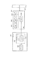
図11は、本実施例において、各種の機器のネットワーク上での配置を示す図である。
【0086】
1101は、ネットワークデバイス管理プログラムが実行されるコンピュータ、1102はディレクトリサービスが動作しているディレクトリサーバ、1103はトラップパケットを監視するトラップ監視プログラムを実行するトラップ監視プログラム実行マシンである。1101、1102および1103のコンピュータの構成は、従来例の説明において図5で示したものと同様の構成が使える。ただし、ディレクトリサーバ1102およびトラップ監視プロセス実行マシン1103においては、キーボードコントローラ505、キーボード509、CRTコントローラ506、CRT510のように、ユーザとの対話を行なうための入出力関連の部分は必ずしも必要ではない。さらに、1101、1102および1103は、同一のコンピュータであっても良い。
【0087】
なお、上記で言うディレクトリサービスとは、言わばネットワークに関する電話帳であり、様々な情報を格納するためのものである。ディレクトリシステムの具体例としては、例えばLDAP(Lightweight Directory Access Protocol)がある。LDAPの規定は、IETFが発行しているRFC1777に記載されている。また解説書としては、例えば株式会社プレンティスホールより「LDAPインターネット ディレクトリ アプリケーション プログラミング」が1997年11月1日に発行されている。
【0088】
本実施例では、ディレクトリサーバとしてLDAPサーバを用いることにして説明を行なうが、LDAPサーバ以外のディレクトリサーバでも本発明の本質を損なわない。
【0089】
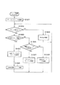
図12は、トラップ監視プログラム実行マシン1103で動作する、トラップの監視プログラムの動作を示すフローチャートである。トラップ監視プログラムは、トラップ監視プログラム実行マシン1103が起動すると同時に起動するように設定されているか、あるいはネットワークの管理者によって明示的に起動されるものとする。
【0090】
トラップ監視プログラムでは、まずステップS1201でディレクトリサーバ1102にネットワークを介して接続し、情報を登録する準備をする。接続するディレクトリサーバのアドレスは、システム管理者によってあらかじめ登録されており、例えばファイルに記録されてハードディスク511に格納されているものとする。次にステップS1202で、パケットの受信があったかどうかを調べる。これは、OSが提供するAPIを呼び出すことにより、OSがNIC508の状態を調べることによって行われる。パケットの受信があった場合ステップS1203に進み、受信パケットがSNMPトラップであるかどうかを判断する。受信パケットのフォーマットが図7で説明したSNMPパケットに合致しており、かつPDUタイプ711のフィールドの値がトラップを示す値であったときにSNMPトラップパケットであると判断する。ステップS1203で受信パケットがSNMPトラップであると判断された場合にはステップS1204に進む。ステップS1204では、受信パケットの送信元アドレスフィールドを見て、送信したデバイスのアドレスを取り出す。次にステップS1205に進み、ステップS1204で取り出したデバイスのアドレスをディレクトリサーバ1102に送信してディレクトリサービスに登録する。
【0091】
一方、ステップS1203でSNMPトラップ受信ではないと判断された場合、ステップS1206に進みSNMPトラップ受信以外の受信処理を行なう。あるいは、ステップS1202でパケット受信ではないと判断された場合には、ステップS1207に進み、パケット受信以外のその他の処理を行なう。
【0092】
ステップS1205、S1206あるいはS1207の処理が終了したら、ステップS1202に戻って処理を続ける。
【0093】
図13は、クライアント1101で実行されるデバイス制御プログラムにおいて、デバイスリストを表示する動作を示すフローチャートである。図13の手順は、クライアント1101においてデバイス管理プログラムが起動した場合、あるいはユーザの操作によって明示的に起動される。
【0094】
デバイスリスト表示動作においては、まずステップS1301で、ディレクトリサーバに接続する。接続するディレクトリサーバのアドレスは、システム管理者によってあらかじめ登録されており、例えばファイルに記録されてハードディスク511に格納されているものとする。そのアドレスは、トラップ監視プログラム実行マシン1103のトラップ監視プログラムが接続するディレクトリサーバのアドレスと同じである。次にステップS1302において、ステップS1301で接続したディレクトリサーバから、ディレクトリサービスに登録されている情報を取り出す。次にステップS1303で、CRTC506を操作してCRT510上にステップS1302で取得した情報を表示する。
【0095】
図14は、ステップS1303における表示の様子を示す図である。ウィンドウ1401に、ディレクトリサーバから取得したデバイスのアドレス一覧が表示されている。
【0096】
以上のようにして、トラップ監視プロセスにより、ネットワーク上のデバイスが起動時にブロードキャストするコールドスタートトラップを補足してそのデバイスのアドレスを取得し、それをディレクトリサーバに登録する。こうすることで、デバイスの探索を能動的に行うことなくネットワークに接続されているデバイスのアドレスを把握できる。このため、能動的に探索パケットの発行が不要となり、ネットワークのトラフィックが軽減できる。
【0097】
(第2の実施の形態)
トラップパケットは、SNMPによるデバイス管理において一般的なものであるので、トラップパケットが、探索の対象としているデバイス種別からのものであることを確認してからディレクトリサービスに登録した方が、後にクライアントがディレクトリサービスにアクセスすることを考えると都合がよい。つまり、例えばクライアントがネットワークプリンタのみを制御対象にしているような場合には、トラップパケットを送信したデバイスがプリンタであることを確認してからディレクトリサービスに登録する方がより望ましい。
【0098】
さらにトラップパケットを受信した時には、デバイスの種別を確認するためのパケットとしてデバイスの状態を問い合わせるパケットを用いることにより、デバイスに関するより詳細な情報を得ることができる。
【0099】
本発明第2の実施例は、これらの点の改良を図ったものである。
【0100】
以下第2の実施例においては、制御対象のネットワークデバイスがネットワークプリンタであるとして説明を進める。
【0101】
図15は、本発明の第2の実施例において、トラップ監視プログラム実行マシン1103で実行されるトラップ監視プログラムの動作について説明したフローチャートである。
【0102】
この図においてステップS1501からS1504までは、第1の実施例において図12を用いて説明したS1201からS1204までの動作と全く同じであるので説明を省略する。同様に、S1508とS1206およびS1509とS1207はそれぞれ同じであるので説明を省略する。
【0103】
ステップS1505においては、トラップパケットを送信してきたデバイスがネットワークプリンタであることを確認するために、ネットワークプリンタがインプリメントしているであろうMIBオブジェクトを取得するためのSNMPパケットを送信する。より具体的には、例えばRFC1514 Host Resources MIBに規定されているhrPrinterDetectedErrorStateを取得すべくGet−Nextパケットを送信する。このMIBオブジェクトは、プリンタの状態を表すものであり、デバイスに問い合わせる情報としてこのMIBオブジェクトを用いることにより、プリンタであることを確認するとともに、同時にデバイスに関するより詳細な情報を得ることができる。
【0104】
ステップS1503でSNMPトラップ以外のパケットの受信であると判断されたら、ステップS1506に進み、そのパケットがSNMPパケットで、かつネットワークプリンタを示す正常応答であるかどうかを判断する。より具体的には、受信したパケットがステップS1505で送信したGet−Nextパケットに対するGet−Response応答パケットであることをリクエストIDフィールド712の値が同じであることを確認することにより行なうとともに、MIB情報フィールド715に含まれている取得したMIBのオブジェクトIDがhrPrinterDetectedErrorState.Xであることを確認する。ここでXは、トラップパケットを送信したデバイスのMIBエージェントにおけるプリンタデバイスを示すインデックス値を示す。
【0105】
もし取得したMIBのオプジェクトIDがhrPrinterDetectedErrorState.Xであった場合には、トラップパケットを送信したデバイスをネットワークプリンタであると判断し、ステップS1507に進む。一方、オブジェクトIDがhrPrinterDetectedErrorStateの次のオブジェクトであった場合、あるいはエラーステータスフィールド713の値がオブジェクトなし(noSuchObject)であった場合には、トラップパケットを送信したデバイスはプリンタではないと判断し、ステップS1508に進む。
【0106】
ステップS1507では、ステップS1501で接続したLDAPサーバに、トラップパケットを送信したデバイスのネットワークアドレス、そのデバイスがプリンタであることを示すフラグおよびステップS1506で取得したhrPrinterDetectedErrorState.Xの値を登録する。
【0107】
図16は、ステップS1507で登録した情報をクライアント1101が表示している様子を示した図である。表示手順については、図13で説明したのと同様であるので省略する。
【0108】
図13の情報と比較して、デバイスがプリンタであることがアイコンで示されている他、デバイスの状態に関する情報が追加されている。例えば1603は、デバイスに何らかの警告エラーが生じていることを示している。1602は、デバイスタイプがプリンタであるとの確認がとれていないデバイスを示している。
【0109】
以上のようにして、トラップ監視プロセスにより、ネットワーク上のデバイスが起動時にブロードキャストするコールドスタートトラップを補足してそのデバイスのアドレスを取得し、そのアドレスを有するデバイスに対して、その状態を問い合わせる。この問合せに対する応答に応じて、アドレスと共に得られた状態をディレクトリサーバに登録する。こうすることで、デバイスの探索を能動的に行うことなくネットワークに接続されているデバイスのアドレスを把握できる。このため、能動的に探索パケットの発行が不要となり、ネットワークのトラフィックが軽減できる。それに加えて、状態の問合せにより、そのデバイスの種類や稼働状態をディレクトリに登録することができ、利用者はより詳細な情報を獲得することができる。
【0110】
上記で説明した本発明に係るネットワークデバイス探索プログラムは、外部からインストールされるプログラムによって、PC500によって遂行されても良い。その場合、そのプログラムはCD−ROMやフラッシュメモリやフロッピーディスクなどの記憶媒体により、あるいは電子メールやパソコン通信などのネットワークを介して、外部の記憶媒体からプログラムを含む情報群をPC500上にロードすることにより、PC500に供給される場合でも本発明は適用されるものである。
【0111】
図17は、記憶媒体の一例であるCD−ROMのメモリマップを示す図である。9999はディレクトリ情報を記憶してある領域で、以降のインストールプログラムを記憶してある領域9998およびネットワークデバイス探索プログラムを記憶してある領域9997の位置を示している。9998は、インストールプログラムを記憶してある領域である。9997は、ネットワークデバイス制御プログラムを記憶してある領域である。本発明のネットワーク探索プログラムがPC500にインストールされる際には、まずインストールプログラムを記憶してある領域9998に記憶されているインストールプログラムがシステムにロードされ、CPU501によって実行される。次に、CPU501によって実行されるインストールプログラムが、ネットワークデバイス探索プログラムを記憶してある領域9997からネットワークデバイス探索プログラムを読み出して、ハードディスク511に格納する。
【0112】
なお、本発明は、複数の機器(例えばホストコンピュータ、インタフェース機器、リーダなど)から構成されるシステムあるいは統合装置に適用しても、ひとつの機器からなる装置に適用してもよい。
【0113】
また、前述した実施形態の機能を実現する、図12、図13あるいは図15に記載された手順のプログラムコードを記録した記憶媒体を、システムあるいは装置に供給し、そのシステムあるいは装置のコンピュータ(またはCPUやMPU)が記憶媒体に格納されたプログラムコードを読み出し実行することによっても、本発明の目的が達成される。
【0114】
この場合、記憶媒体から読み出されたプログラムコード自体が本発明の新規な機能を実現することになり、そのプログラムコードを記憶した記憶媒体は本発明を構成することになる。
【0115】
プログラムコードを供給するための記憶媒体としては、例えば、フロッピーディスク、ハードディスク、光ディスク、光磁気ディスク、CD−ROM、CD−R、磁気テープ、不揮発性のメモリカード、ROMなどを用いることができる。
【0116】
また、コンピュータが議み出したプログラムコードを実行することによって、前述した実施形態の機能が実現される他、そのプログラムコードの指示に基づき、コンピュータ上で稼動しているOSなどが実際の処理の一部または全部を行い、その処理によっても前述した実施形態の機能が実現され得る。
【0117】
さらに、記憶媒体から読み出されたプログラムコードが、コンピュータに挿入された機能拡張ボードやコンピュータに接続された機能拡張ユニットに備わるメモリに書き込まれた後、そのプログラムコードの指示に基づき、その機能拡張ボードや機能拡張ユニットに備わるCPUなどが実際の処理の一部または全部を行い、その処理によっても前述した実施形態の機能が実現され得る。
【0118】
なお、本発明は、前述した実施形態の機能を実現するソフトウェアのプログラムコードを記録した記憶媒体から、そのプログラムをパソコン通信など通信ラインを介して要求者にそのプログラムを配信する場合にも適用できる。
【0119】
【発明の効果】
以上説明したように、本発明によれば、デバイス管理装置が能動的にブロードキャストパケットを送信することなくネットワークデバイスの情報を取得することができる。このため、デバイス探索のためにネットワークの負荷が増大することを防止できる。
【図面の簡単な説明】
【図1】プリンタをネットワークに接続するためのネットワークボードを、開放型アーキテクチャを持つプリンターへつなげた場合を示す図である。
【図2】エージェントを実装したネットワークボードをプリンタに接続する実施形態を示す断面図である。
【図3】ネットワークボードとプリンターとLANとの電気的接続を示すブロック図である。
【図4】MIBの構造を示す概念図である。
【図5】ネットワーク管理ソフトウェアが稼動可能なPCの構成を示すブロック図である。
【図6】ネットワーク管理ソフトウェアのモジュール構成図である。
【図7】SNMPメッセージのフォーマットである。
【図8】マネージャとエージェント間でのSNMPコマンドのやりとりを示す図である。
【図9】MIBモジュールAPIを示す図である。
【図10】従来例における探索モジュールとデバイス間の通信シーケンスを示す図である。
【図11】機器のネットワーク上での配置を示す図である。
【図12】トラップの監視プログラムの動作を示すフローチャートである。
【図13】デバイスリストを表示する動作を示すフローチャートである。
【図14】デバイス一覧の表示の様子を示す図である。
【図15】第2の実施例におけるトラップの監視プログラムの動作を示すフローチャートである。
【図16】第2の実施例におけるデバイス一覧の表示の様子を示す図である。
【図17】本発明のネットワーク管理ソフトウェアの記憶媒体におけるメモリマップを示す図である。
【符号の説明】
S1101 クライアント
S1102 ディレクトリサーバ
S1103 トラップ監視プログラム実行マシン
S1104 ネットワークデバイス
S1202 パケット受信手段
S1203 トラップパケット受信判断手段
S1204 デバイスアドレス取得手段
S1205 デバイスアドレス登録手段
S1505 確認パケット送信手段
S1506 応答パケット確認手段[0001]
BACKGROUND OF THE INVENTION
The present invention relates to a network device management apparatus and method for managing, for example, devices connected to a computer network.
[0002]
[Prior art]
In recent years, a local area network (LAN) in which computers are connected to each other has become widespread, and such a local area network is constructed over a building floor or an entire building, a group of buildings (premises), a region, or a larger area. be able to. Such networks are further interconnected and can be connected to global networks. Each such interconnected LAN may have a variety of hardware interconnection technologies and a number of network protocols.
[0003]
A simple LAN separated from others can be managed by individual users. That is, the user can replace the device, install software, or diagnose a problem.
[0004]
However, large-scale complex LANs and large interconnected LAN groups require “management”. “Management” means management by both a human network administrator and software used by the administrator. In the present application, “management” means management by software for managing the entire system, and “user” means a person who uses network management software. This user is usually the system administrator. By using network management software, the user can obtain management data on the network and change this data.
[0005]
A large-scale network system is usually a dynamic system that requires constant addition and removal of devices, software update, and problem detection. In general, there are various systems owned by various people and supplied by various vendors.
[0006]
As a method for managing devices on a network constituting such a large-scale network system, several attempts have been made so far by many standard organizations. The International Organization for Standardization (ISO) provided a general-purpose reference framework called the Open System Interconnection (OSI) model. The OSI model of the network management protocol is called a common management information protocol (CMIP). CMIP is Europe's common network management protocol.
[0007]
In recent years, as a more common network management protocol, there is a variant protocol related to CMIP called Simple Network Management Protocol (SNMP). (See "Introduction to TCP / IP network management for practical management" MT Rose = work / Takeshi Nishida = translation Toppan Co., Ltd., published on August 20, 1992.)
According to this SNMP network management technology, a network management system includes at least one network management station (NMS), several managed nodes each including an agent, and management stations and agents for exchanging management information. Contains the network management protocol to use. The user can obtain data on the network and change the data by communicating with the agent software on the managed node using the network management software on the NMS.
[0008]
Here, the agent is software that runs as a background process for each target device. When the user requests management data from a device on the network, the management software puts object identification information in a management packet or frame and sends it to the target agent. The agent interprets the object identification information, retrieves data corresponding to the object identification information, puts the data in a packet, and sends it back to the user. Sometimes the corresponding process is invoked to retrieve the data.
[0009]
In addition, the agent holds data on its state in the form of a database. This database is called MIB (Management Information Base). FIG. 4 is a conceptual diagram showing the structure of the MIB. As shown in FIG. 4, the MIB has a tree data structure, and all nodes are uniquely numbered. In FIG. 4, the number written in parentheses is the identifier of the node. For example, the identifier of the
[0010]
The structure of this MIB is called a structure of management information (SMI) and is defined in RFC1155 Structure and Identificatlon of Management Information for TCP / IP-based Internets.
[0011]
FIG. 4 shows only some of the MIBs defined as standards.
[0012]
Next, the SNMP protocol will be briefly described. A PC (hereinafter referred to as a manager) on which network management utility software is operating and a managed network device (hereinafter referred to as an agent) on which an SNMP agent is operating communicate with each other using the SNMP protocol. Do. There are five types of commands in the SNMP protocol, which are called Get-request, Get-next-request, Get-response, Set-request, and Trap, respectively. FIG. 8 shows how these commands are exchanged between the manager and the agent.
[0013]
Get-request and Get-next-request are commands that the manager sends to the agent in order to obtain the value of the MIB object of the agent. Upon receiving this command, the agent sends a Get-response command to the manager in order to notify the manager of the MIB value (801 and 802).
[0014]
Set-request is a command that the manager sends to the agent in order for the manager to set the value of the MIB object of the agent. Upon receiving this command, the agent sends a Get-response command to the manager in order to notify the manager of the setting result (803).
[0015]
Trap is a command sent by the agent to the manager so that the agent notifies the manager of a change in the state of the agent (804).
[0016]
FIG. 7 shows formats of commands other than Trap, that is, Get-request, Get-next-request, Get-response, and Set-request.
[0017]
700 indicates an SNMP message. The SNMP message includes a
[0018]
Next, a large-scale network that needs to be managed will be described.
[0019]
FIG. 1 is a diagram illustrating a case where a network board (NB) 101 for connecting a printer to a network is connected to a
[0020]
A plurality of personal computers (PCs) such as the
[0021]
In addition, a
[0022]
More specifically, the network shown in FIG. 1 can use network software such as Novell or UNIX software in order to efficiently communicate between various network members. Any network software can be used, but for example, Novell NetWare (trademark of Novell, hereinafter omitted) software can be used. See the online documentation included with the NetWare package for a detailed description of this software package. It can be purchased from Novell with a NetWare package.
[0023]
Briefly describing the configuration of FIG. 1, the
[0024]
Each of the
[0025]
Typically, a LAN, such as
[0026]
Therefore, as shown in FIG. 1, the
[0027]
As an example of agent installation, it is conceivable to install an agent on a network board for connecting a printer to a network. As a result, the printer can be managed by the network management software. The user can obtain information on the printer to be controlled using the network management software and can change the status. More specifically, for example, a character string displayed on a liquid crystal display of a printer can be acquired, or a default paper feed cassette can be changed. Hereinafter, an embodiment in which a network board (NB) on which an agent is mounted is connected to a printer will be described. As shown in FIG. 2, the
[0028]
An important factor in this NB design is the function of accessing the printer control state from the
[0029]
FIG. 2 is a cross-sectional view showing a state where the
[0030]
FIG. 3 is a block diagram showing electrical connections between the
[0031]
The
[0032]
On the other hand, the PC side on which the network management software runs will be described below.
[0033]
FIG. 5 is a block diagram showing a configuration of a PC capable of operating the network management software.
[0034]
In FIG. 5,
[0035]
[0036]
A keyboard controller (KBC) 505 controls an instruction input from a keyboard (KB) 509 or a pointing device (not shown).
[0037]
Next, the configuration of the network management software in the conventional example will be described.
[0038]
The network management apparatus in the conventional example is realized on a PC having the same configuration as the PC capable of realizing the network management apparatus as shown in FIG. The hard disk (HD) 511 stores a network management software program according to the present application, which is an operation subject in all of the descriptions below. In all the descriptions below, unless otherwise specified, the execution subject is the
[0039]
The network management program according to the present application may be supplied in a form stored in a storage medium such as a floppy disk or a CD-ROM. In that case, the floppy disk controller (FD) 512 shown in FIG. A program is read from a storage medium by a CD-ROM drive or the like and installed in a hard disk (HD) 511.
[0040]
FIG. 6 is a module configuration diagram of network management software according to the conventional example. This network management software is stored in the
[0041]
In FIG. 6,
[0042]
The
[0043]
[0044]
612 is called a common transport module, and is a module that absorbs differences in lower-layer protocols for carrying SNMP data. Actually, either the
The
[0045]
An interface between the
[0046]
The
[0047]
First, the host module calls
[0048]
The address specified here is the address of the protocol that is operating, the IP address in the case of the IP protocol, and the NetWare address in the case of the NetWare protocol. It is also possible to specify a broadcast address.
[0049]
When a port is opened by specifying a broadcast address, it is possible to communicate with a plurality of devices that respond to the broadcast address.
[0050]
When the upper module stops using the port, it calls
[0051]
When the upper module reads the MIB object, the
[0052]
An SNMP Get-request command is generated by calling the
[0053]
When the upper module writes to the MIB object, the
[0054]
An SNMP Get-request command is generated by calling the
[0055]
The callback function is for notifying the upper module of the result of the
[0056]
When
[0057]
Next, a specific data flow will be described. The
[0058]
A packet from a device connected to the
[0059]
In the following description, the network management software according to the present application is referred to as “NetSpot”.
[0060]
Files necessary for installing NetSpot are usually recorded and distributed on a physical medium such as a floppy disk (FD) or CD-ROM, or transmitted via a network. The user obtains files necessary for NetSpot installation by these means, and then starts installation of NetSpot according to a predetermined installation procedure.
[0061]
The installation procedure of NetSpot is the same as the installation procedure of other general software. That is, when the user starts the NetSpot installer on the personal computer (PC), the installer automatically executes the installation thereafter. The installer copies files necessary for the operation of NetSpot to the hard disk of the PC, and corrects or creates a new file necessary for the operation of NetSpot while receiving information from the user as necessary.
[0062]
Next, a search sequence in the network management program in this conventional example will be described.
[0063]
FIG. 10 is a diagram showing a search sequence in a conventional network management program.
[0064]
In FIG. 10, a
[0065]
A
[0066]
A
[0067]
When an instruction to start a search is issued from the upper module, the search module sends a Get request SNMP packet for specifying the broadcast address and acquiring the device status and device type to the network (1001 and 1002). This packet is delivered to all devices connected to the network.
[0068]
Here, as the MIB object to be inquired, only a standard MIB is used in 1001, and a private MIB is used in 1002. The reason for inquiring different MIB objects is to find both a device having a private MIB and a device having only a standard MIB.
[0069]
In response to this SNMP packet, each network device equipped with an SNMP agent sends a response packet (1003 to 1006).
[0070]
Here, 1003 is a response of the
[0071]
Since a
[0072]
More specifically, since the
[0073]
Similarly, since a normal response is returned from both the standard MIB and the private MIB from the
[0074]
This acquisition and the response of the
Further, when the
[0075]
When the time further elapses and the
[0076]
[Problems to be solved by the invention]
However, in the above-described conventional example, the device management apparatus searches for devices by actively transmitting broadcast packets.
[0077]
Transmitting a broadcast packet in this way means that all network devices that can respond to the SNMP with respect to the packet transmit a reply packet, which significantly increases network traffic. Transmitting a broadcast packet periodically means that a traffic increase phenomenon due to the broadcast packet occurs periodically, and such a situation is not preferable from the viewpoint of network load and management. It is desirable that the number of broadcast packets transmitted be as small as possible.
[0078]
The present invention has been made in view of the above conventional example, and an object of the present invention is to provide a network device management apparatus and method that can acquire information on a network device without increasing the load on the network.
[0079]
[Means for Solving the Problems]
In order to achieve the above object, the present invention comprises the following arrangement. That is, network management to which a device that broadcasts network management packets is connected at least once after startupProcessing in equipmentA method,From multiple devicesA packet receiving step for receiving a packet; a packet determining step for determining whether the packet received in the packet receiving step is the network management packet; and the packet determining step determined to be the network management packet The device address acquisition step of acquiring the address of the device that transmitted the packet from the packet, and the device address acquisition stepMultiple devicesaddressDevice address transfer for transfer to send to the server device to register with a predetermined server device on the networkA process.
[0080]
Alternatively, a network to which a device that broadcasts a network management packet at least once after startup is connectedProcessing inA method,From multiple devicesA packet receiving step for receiving a packet; a packet determining step for determining whether the packet received in the packet receiving step is the network management packet; and the packet determining step determined to be the network management packet In this case, based on the transmission step of transmitting a confirmation packet for confirming that the device is a device to be monitored to the device that has transmitted the packet, the response is determined based on the response to the confirmation packet. ReturnedpluralDevice status with addressDevice address transfer for transfer to send to the server device to register with a predetermined server device on the networkA process.
[0081]
Preferably, the response is a normal response if the response source device is a device to be managed, and includes information indicating an operating state of the device.
More preferably, the transmission step transmits a confirmation packet for acquiring the status of the printer. If the response to the confirmation packet is a normal response, the address registration step includes the device address of the response source and the device. Is registered as a printer.
[0082]
Alternatively, a network to which a device that broadcasts a network management packet at least once after startup is connectedProcessing inA method,From multiple devicesA packet receiving step for receiving a packet; a packet determining step for determining whether the packet received in the packet receiving step is the network management packet; and the packet determining step determined to be the network management packet The device address acquisition step of acquiring the address of the device that transmitted the packet from the packet, and confirming that the device is a device to be monitored with respect to the address acquired in the device address acquisition step A transmitting step for transmitting a confirmation packet for determining, a determination step for determining whether or not a device that has returned the response is a device to be monitored, based on a response corresponding to the confirmation packet; If it is determined in the determination step that the device is a target device, the device Acquired by the scan address acquisition processMultiple devicesAddress the directory serverDevice address transfer process to transfer to register toWith.
[0083]
DETAILED DESCRIPTION OF THE INVENTION
(First embodiment)
As described in the description of the conventional example, the SNMP specification includes a packet structure called a trap. There are several types of traps, of which a so-called cold start trap is broadcast on the network when the device is activated. In the present invention, it is intended to detect that a new device has been added to the network by capturing this cold start trap.
[0084]
Hereinafter, it explains in detail using a drawing.
[0085]
FIG. 11 is a diagram showing the arrangement of various devices on the network in this embodiment.
[0086]
1101 is a computer on which a network device management program is executed, 1102 is a directory server on which a directory service is operating, and 1103 is a trap monitoring program execution machine that executes a trap monitoring program for monitoring trap packets. The configurations of the
[0087]
The directory service mentioned above is a telephone book related to the network, and is used for storing various information. A specific example of the directory system is LDAP (Lightweight Directory Access Protocol). The regulation of LDAP is described in RFC1777 issued by IETF. In addition, as an explanatory book, for example, “LDAP Internet Directory Application Programming” was issued on November 1, 1997 by Prentice Hall Co., Ltd.
[0088]
In the present embodiment, description will be made assuming that an LDAP server is used as the directory server, but the essence of the present invention is not impaired even by a directory server other than the LDAP server.
[0089]
FIG. 12 is a flowchart showing the operation of the trap monitoring program operating on the trap monitoring
[0090]
In step S1201, the trap monitoring program first connects to the
[0091]
On the other hand, if it is determined in step S1203 that the SNMP trap is not received, the process advances to step S1206 to perform a receiving process other than the SNMP trap reception. Alternatively, if it is determined in step S1202 that the packet is not received, the process proceeds to step S1207, and other processes other than the packet reception are performed.
[0092]
When the process of step S1205, S1206, or S1207 ends, the process returns to step S1202 to continue the process.
[0093]
FIG. 13 is a flowchart showing an operation for displaying a device list in the device control program executed by the
[0094]
In the device list display operation, first, in step S1301, a directory server is connected. It is assumed that the address of the directory server to be connected is registered in advance by the system administrator, and is recorded in a file and stored in the
[0095]
FIG. 14 is a diagram illustrating a display state in step S1303. A
[0096]
As described above, the trap monitoring process supplements the cold start trap broadcast by the device on the network at the time of startup, obtains the address of the device, and registers it in the directory server. In this way, it is possible to grasp the address of the device connected to the network without actively searching for the device. This eliminates the need to actively issue a search packet, thereby reducing network traffic.
[0097]
(Second Embodiment)
Since trap packets are common in SNMP device management, it is more likely that the client will later register with the directory service after confirming that the trap packet is from the device type being searched. It is convenient to consider accessing a directory service. In other words, for example, when the client targets only the network printer, it is more desirable to register with the directory service after confirming that the device that transmitted the trap packet is a printer.
[0098]
Further, when a trap packet is received, more detailed information about the device can be obtained by using a packet for inquiring about the state of the device as a packet for confirming the type of the device.
[0099]
In the second embodiment of the present invention, these points are improved.
[0100]
In the following description of the second embodiment, it is assumed that the network device to be controlled is a network printer.
[0101]
FIG. 15 is a flowchart for explaining the operation of the trap monitoring program executed by the trap monitoring
[0102]
In this figure, steps S1501 to S1504 are exactly the same as the operations from S1201 to S1204 described with reference to FIG. 12 in the first embodiment, and thus description thereof is omitted. Similarly, since S1508 and S1206 and S1509 and S1207 are the same, the description thereof is omitted.
[0103]
In step S1505, in order to confirm that the device that has transmitted the trap packet is a network printer, an SNMP packet for acquiring an MIB object that the network printer will implement is transmitted. More specifically, for example, a Get-Next packet is transmitted in order to obtain hrPrinterDetectedErrorState defined in RFC1514 Host Resources MIB. This MIB object represents the status of the printer. By using this MIB object as information for inquiring to the device, it is possible to confirm that the device is a printer and to obtain more detailed information about the device at the same time.
[0104]
If it is determined in step S1503 that a packet other than the SNMP trap is received, the process advances to step S1506 to determine whether the packet is an SNMP packet and a normal response indicating a network printer. More specifically, it is confirmed that the received packet is a Get-Response response packet for the Get-Next packet transmitted in step S1505 by confirming that the value of the
[0105]
If the obtained MIB object ID is hrPrinterDetectedErrorState.X, it is determined that the device that transmitted the trap packet is a network printer, and the process advances to step S1507. On the other hand, if the object ID is the next object after hrPrinterDetectedErrorState, or if the value of the
[0106]
In step S1507, the network address of the device that transmitted the trap packet, the flag indicating that the device is a printer, and the value of hrPrinterDetectedErrorState.X acquired in step S1506 are registered in the LDAP server connected in step S1501.
[0107]
FIG. 16 is a diagram showing a state in which the
[0108]
Compared with the information in FIG. 13, an icon indicating that the device is a printer is added, and information regarding the state of the device is added. For example, 1603 indicates that some warning error has occurred in the device.
[0109]
As described above, the trap monitoring process supplements the cold start trap broadcast by the device on the network at the time of startup, acquires the address of the device, and inquires of the device having the address of the status. In response to a response to this inquiry, the state obtained together with the address is registered in the directory server. In this way, it is possible to grasp the address of the device connected to the network without actively searching for the device. This eliminates the need to actively issue a search packet, thereby reducing network traffic. In addition, the device type and operating status can be registered in the directory by the status inquiry, and the user can acquire more detailed information.
[0110]
The network device search program according to the present invention described above may be executed by the
[0111]
FIG. 17 is a diagram showing a memory map of a CD-ROM which is an example of a storage medium.
[0112]
Note that the present invention may be applied to a system or an integrated device including a plurality of devices (for example, a host computer, an interface device, a reader, etc.) or an apparatus including a single device.
[0113]
In addition, a storage medium that records the program code of the procedure described in FIG. 12, FIG. 13, or FIG. 15 that realizes the functions of the above-described embodiments is supplied to the system or apparatus, and the computer of the system or apparatus (or The object of the present invention is also achieved when the CPU or MPU) reads and executes the program code stored in the storage medium.
[0114]
In this case, the program code itself read from the storage medium realizes the novel function of the present invention, and the storage medium storing the program code constitutes the present invention.
[0115]
As a storage medium for supplying the program code, for example, a floppy disk, a hard disk, an optical disk, a magneto-optical disk, a CD-ROM, a CD-R, a magnetic tape, a nonvolatile memory card, a ROM, or the like can be used.
[0116]
In addition, the functions of the above-described embodiments are realized by executing the program code that is discussed by the computer, and the OS that is running on the computer performs the actual processing based on the instruction of the program code. The functions of the above-described embodiments can be realized by performing part or all of the processing.
[0117]
Further, after the program code read from the storage medium is written to a memory provided in a function expansion board inserted into the computer or a function expansion unit connected to the computer, the function expansion is performed based on the instruction of the program code. The CPU or the like provided in the board or the function expansion unit performs part or all of the actual processing, and the functions of the above-described embodiments can be realized by the processing.
[0118]
The present invention can also be applied to a case where the program is distributed to a requester via a communication line such as personal computer communication from a storage medium in which a program code of software realizing the functions of the above-described embodiments is recorded. .
[0119]
【The invention's effect】
As described above, according to the present invention, the device management apparatus can acquire network device information without actively transmitting a broadcast packet. For this reason, it is possible to prevent an increase in network load for device search.
[Brief description of the drawings]
FIG. 1 is a diagram illustrating a case where a network board for connecting a printer to a network is connected to a printer having an open architecture.
FIG. 2 is a cross-sectional view showing an embodiment in which a network board on which an agent is mounted is connected to a printer.
FIG. 3 is a block diagram showing an electrical connection between a network board, a printer, and a LAN.
FIG. 4 is a conceptual diagram showing the structure of an MIB.
FIG. 5 is a block diagram showing a configuration of a PC capable of operating network management software.
FIG. 6 is a module configuration diagram of network management software.
FIG. 7 is a format of an SNMP message.
FIG. 8 is a diagram showing an SNMP command exchange between a manager and an agent.
FIG. 9 is a diagram showing a MIB module API.
FIG. 10 is a diagram showing a communication sequence between a search module and a device in a conventional example.
FIG. 11 is a diagram illustrating an arrangement of devices on a network.
FIG. 12 is a flowchart showing the operation of a trap monitoring program.
FIG. 13 is a flowchart illustrating an operation for displaying a device list.
FIG. 14 is a diagram illustrating a display state of a device list.
FIG. 15 is a flowchart showing the operation of a trap monitoring program in the second embodiment;
FIG. 16 is a diagram showing how a device list is displayed in the second embodiment.
FIG. 17 is a diagram showing a memory map in the storage medium of the network management software of the present invention.
[Explanation of symbols]
S1101 client
S1102 directory server
S1103 Trap monitoring program execution machine
S1104 Network device
S1202 Packet receiving means
S1203 Trap packet reception determination means
S1204 Device address acquisition means
S1205 Device address registration means
S1505 confirmation packet transmission means
S1506 Response packet confirmation means
Claims (12)
複数のデバイスからパケットを受信するパケット受信工程と、
前記パケット受信工程で受信したパケットが、前記ネットワーク管理用パケットであるか判定するパケット判定工程と、
前記パケット判定工程で前記ネットワーク管理用パケットであると判断された場合、当該パケットから、当該パケットを送信したデバイスのアドレスを取得するデバイスアドレス取得工程と、
前記デバイスアドレス取得工程で取得された複数のデバイスのアドレスを前記ネットワーク上の所定のサーバ装置に登録するべく前記サーバ装置へ送出するべく転送するデバイスアドレス転送工程と
を備えることを特徴とする処理方法。 A processing method in a network management apparatus to which a device that broadcasts a network management packet at least once after startup is connected,
A packet receiving process for receiving packets from a plurality of devices ;
A packet determination step of determining whether the packet received in the packet reception step is the network management packet;
When it is determined in the packet determination step that the packet is for network management, from the packet, a device address acquisition step of acquiring the address of the device that transmitted the packet;
Processing method characterized in that it comprises a device address transfer step of transferring to the delivery to the server device in order to register the address of a plurality of devices acquired by said device address acquiring step to a predetermined server device on the network .
複数のデバイスからパケットを受信するパケット受信工程と、
前記パケット受信工程で受信したパケットが、前記ネットワーク管理用パケットであるか判定するパケット判定工程と、
前記パケット判定工程で前記ネットワーク管理用パケットであると判断された場合、当該パケットを送信したデバイスに対して、当該デバイスが監視の対象となるデバイスであることを確認するための確認パケットを送信する送信工程と、
前記確認パケットに対する応答に基づいて、当該応答を返した複数のデバイスの状態をアドレスと共に前記ネットワーク上の所定のサーバ装置に登録するべく前記サーバ装置へ送出するべく転送するデバイスアドレス転送工程と
を備えることを特徴とする処理方法。 A processing method in a network to which a device that broadcasts a network management packet at least once after startup is connected,
A packet receiving process for receiving packets from a plurality of devices ;
A packet determination step of determining whether the packet received in the packet reception step is the network management packet;
When it is determined that the packet is the network management packet in the packet determination step, a confirmation packet for confirming that the device is a device to be monitored is transmitted to the device that transmitted the packet. Sending process;
A device address transfer step of transferring , based on a response to the confirmation packet, the states of the plurality of devices that have returned the response together with addresses to be sent to the server device so as to be registered in the predetermined server device on the network. A processing method characterized by the above.
複数のデバイスからパケットを受信するパケット受信工程と、
前記パケット受信工程で受信したパケットが、前記ネットワーク管理用パケットであるか判定するパケット判定工程と、
前記パケット判定工程で前記ネットワーク管理用パケットであると判断された場合、当該パケットから、当該パケットを送信したデバイスのアドレスを取得するデバイスアドレス取得工程と、
前記デバイスアドレス取得工程で取得されたアドレスに対して、デバイスが監視の対象となるデバイスであることを確認するための確認パケットを送信する送信工程と、
前記確認パケットに対応する応答に基づいて、当該応答を返したデバイスが、監視の対象となるデバイスであるか否かを判定する判定工程と、
監視対象となるデバイスであると前記判定工程で判定された場合、前記デバイスアドレス取得工程で取得された複数のデバイスのアドレスをディレクトリサーバに登録するべく 転送するデバイスアドレス転送工程とを備えることを特徴とする処理方法。 A processing method in a network to which a device that broadcasts a network management packet at least once after startup is connected,
A packet receiving process for receiving packets from a plurality of devices ;
A packet determination step of determining whether the packet received in the packet reception step is the network management packet;
When it is determined in the packet determination step that the packet is for network management, from the packet, a device address acquisition step of acquiring the address of the device that transmitted the packet;
A transmission step of transmitting a confirmation packet for confirming that the device is a device to be monitored with respect to the address acquired in the device address acquisition step;
A determination step of determining whether a device that has returned the response is a device to be monitored based on a response corresponding to the confirmation packet;
A device address transfer step of transferring the addresses of the plurality of devices acquired in the device address acquisition step to register them in a directory server when it is determined in the determination step that the device is a monitoring target device. Processing method.
複数のデバイスからパケットを受信するパケット受信手段と、
前記パケット受信手段で受信したパケットが、前記ネットワーク管理用パケットであるか判定するパケット判定手段と、
前記パケット判定手段で前記ネットワーク管理用パケットであると判断された場合、当該パケットから、当該パケットを送信したデバイスのアドレスを取得するデバイスアドレス取得手段と、
前記デバイスアドレス取得手段で取得された複数のデバイスのアドレスを前記ネットワーク上の所定のサーバ装置に登録するべく前記サーバ装置へ送出するべく転送するデバイスアドレス転送手段と
を備えることを特徴とするネットワークデバイス管理装置。A network management device connected to a device that broadcasts a network management packet at least once after startup;
A packet receiving means for receiving packets from a plurality of devices ;
A packet determination means for determining whether the packet received by the packet reception means is the network management packet;
If the packet determination unit determines that the packet is the network management packet, device address acquisition unit that acquires the address of the device that transmitted the packet from the packet;
A network device comprising: device address transfer means for transferring addresses of a plurality of devices acquired by the device address acquisition means to be transmitted to the server apparatus so as to be registered in a predetermined server apparatus on the network. Management device.
複数のデバイスからパケットを受信するパケット受信手段と、
前記パケット受信手段で受信したパケットが、前記ネットワーク管理用パケットであるか判定するパケット判定手段と、
前記パケット判定手段で前記ネットワーク管理用パケットであると判断された場合、当該パケットを送信したデバイスに対して、当該デバイスが監視の対象となるデバイスであることを確認するための確認パケットを送信する送信手段と、
前記確認パケットに対する応答に基づいて、当該応答を返した複数のデバイスの状態をアドレスと共に前記ネットワーク上の所定のサーバ装置に登録するべく前記サーバ装置へ送出するべく転送するデバイスアドレス転送手段と
を備えることを特徴とするネットワークデバイス管理装置。A network management device connected to a device that broadcasts a network management packet at least once after startup;
A packet receiving means for receiving packets from a plurality of devices ;
A packet determination means for determining whether the packet received by the packet reception means is the network management packet;
When the packet determining unit determines that the packet is the network management packet, a confirmation packet for confirming that the device is a device to be monitored is transmitted to the device that has transmitted the packet. A transmission means;
Device address transfer means for transferring , based on a response to the confirmation packet, the states of the plurality of devices that have returned the response together with addresses to be sent to the server device so as to be registered in a predetermined server device on the network. A network device management apparatus.
複数のデバイスからパケットを受信するパケット受信手段と、
前記パケット受信手段で受信したパケットが、前記ネットワーク管理用パケットであるか判定するパケット判定手段と、
前記パケット判定手段で前記ネットワーク管理用パケットであると判断された場合、当該パケットから、当該パケットを送信したデバイスのアドレスを取得するデバイスアドレス取得手段と、
前記デバイスアドレス取得手段で取得されたアドレスに対して、デバイスが監視の対象となるデバイスであることを確認するための確認パケットを送信する送信手段と、
前記確認パケットに対応する応答に基づいて、当該応答を返したデバイスが、監視の対象となるデバイスであるか否かを判定する判定手段と、
監視対象となるデバイスであると前記判定手段で判定された場合、前記デバイスアドレス取得手段で取得された複数のデバイスのアドレスをディレクトリサーバに登録するべく転送するデバイスアドレス転送手段と
を備えることを特徴とするネットワークデバイス管理装置。A network management device connected to a device that broadcasts a network management packet at least once after startup;
A packet receiving means for receiving packets from a plurality of devices ;
A packet determination means for determining whether the packet received by the packet reception means is the network management packet;
If the packet determination unit determines that the packet is the network management packet, device address acquisition unit that acquires the address of the device that transmitted the packet from the packet;
Transmitting means for transmitting a confirmation packet for confirming that the device is a device to be monitored with respect to the address obtained by the device address obtaining means;
A determination unit that determines whether the device that has returned the response is a device to be monitored based on a response corresponding to the confirmation packet;
Device address transfer means for transferring the addresses of the plurality of devices acquired by the device address acquisition means to register them in a directory server when the determination means determines that the device is a monitoring target device. Network device management device.
複数のデバイスからパケットを受信するパケット受信工程と、
前記パケット受信工程で受信したパケットが、前記ネットワーク管理用パケットであるか判定するパケット判定工程と、
前記パケット判定工程で前記ネットワーク管理用パケットであると判断された場合、当該パケットから、当該パケットを送信したデバイスのアドレスを取得するデバイスアドレス取得工程と、
前記デバイスアドレス取得工程で取得された複数のデバイスのアドレスを前記ネットワーク上の所定のサーバ装置に登録するべく前記サーバ装置へ送出するべく転送するデバイスアドレス転送工程と
をコンピュータにより実行させることを特徴とするコンピュータ可読記録媒体。A computer-readable recording medium recording a program for realizing a processing method by a computer in a network management apparatus to which a device that broadcasts a network management packet is connected at least once after startup.
A packet receiving process for receiving packets from a plurality of devices ;
A packet determination step of determining whether the packet received in the packet reception step is the network management packet;
When it is determined in the packet determination step that the packet is for network management, from the packet, a device address acquisition step of acquiring the address of the device that transmitted the packet;
And a device address transfer step of transferring the addresses of the plurality of devices acquired in the device address acquisition step to be sent to the server device so as to be registered in a predetermined server device on the network. A computer-readable recording medium.
複数のデバイスからパケットを受信するパケット受信工程と、
前記パケット受信工程で受信したパケットが、前記ネットワーク管理用パケットであるか判定するパケット判定工程と、
前記パケット判定工程で前記ネットワーク管理用パケットであると判断された場合、当該パケットを送信したデバイスに対して、当該デバイスが監視の対象となるデバイスであることを確認するための確認パケットを送信する送信工程と、
前記確認パケットに対する応答に基づいて、当該応答を返した複数のデバイスの状態をアドレスと共に前記ネットワーク上の所定のサーバ装置に登録するべく前記サーバ装置へ送出するべく転送するデバイスアドレス転送工程と
をコンピュータにより実行させることを特徴とするコンピュータ可読記録媒体。A computer-readable recording medium recording a program for realizing by a computer a processing method in a network to which a device that broadcasts a network management packet is connected at least once after startup.
A packet receiving process for receiving packets from a plurality of devices ;
A packet determination step of determining whether the packet received in the packet reception step is the network management packet;
When it is determined that the packet is the network management packet in the packet determination step, a confirmation packet for confirming that the device is a device to be monitored is transmitted to the device that transmitted the packet. Sending process;
A device address transfer step of transferring , based on a response to the confirmation packet, the states of a plurality of devices that have returned the response together with addresses to be sent to the server device to be registered in the predetermined server device on the network; And a computer-readable recording medium.
複数のデバイスからパケットを受信するパケット受信工程と、
前記パケット受信工程で受信したパケットが、前記ネットワーク管理用パケットであるか判定するパケット判定工程と、
前記パケット判定工程で前記ネットワーク管理用パケットであると判断された場合、当該パケットから、当該パケットを送信したデバイスのアドレスを取得するデバイスアドレス取得工程と、
前記デバイスアドレス取得工程で取得されたアドレスに対して、デバイスが監視の対象となるデバイスであることを確認するための確認パケットを送信する送信工程と、
前記確認パケットに対応する応答に基づいて、当該応答を返したデバイスが、監視の対象となるデバイスであるか否かを判定する判定工程と、
監視対象となるデバイスであると前記判定工程で判定された場合、前記デバイスアドレス取得工程で取得された複数のデバイスのアドレスをディレクトリサーバに登録するべく転送するデバイスアドレス転送工程と
をコンピュータにより実行させることを特徴とするコンピュータ可読記録媒体。A computer-readable recording medium recording a program for realizing by a computer a processing method in a network to which a device that broadcasts a network management packet is connected at least once after startup.
A packet receiving process for receiving packets from a plurality of devices ;
A packet determination step of determining whether the packet received in the packet reception step is the network management packet;
When it is determined in the packet determination step that the packet is for network management, from the packet, a device address acquisition step of acquiring the address of the device that transmitted the packet;
A transmission step of transmitting a confirmation packet for confirming that the device is a device to be monitored with respect to the address acquired in the device address acquisition step;
A determination step of determining whether a device that has returned the response is a device to be monitored based on a response corresponding to the confirmation packet;
When it is determined in the determination step that the device is a monitoring target device, the computer executes a device address transfer step of transferring the addresses of the plurality of devices acquired in the device address acquisition step to register them in a directory server A computer-readable recording medium.
Priority Applications (5)
| Application Number | Priority Date | Filing Date | Title |
|---|---|---|---|
| JP16556999A JP3684108B2 (en) | 1999-06-11 | 1999-06-11 | Network device management apparatus and method |
| US09/588,672 US6981036B1 (en) | 1999-06-11 | 2000-06-06 | Network device managing apparatus and method |
| EP00304814A EP1059766B1 (en) | 1999-06-11 | 2000-06-07 | Network device managing apparatus and method |
| EP07075576A EP1838035A3 (en) | 1999-06-11 | 2000-06-07 | Network device managing apparatus and method |
| DE60035830T DE60035830T2 (en) | 1999-06-11 | 2000-06-07 | Network device management device and method |
Applications Claiming Priority (1)
| Application Number | Priority Date | Filing Date | Title |
|---|---|---|---|
| JP16556999A JP3684108B2 (en) | 1999-06-11 | 1999-06-11 | Network device management apparatus and method |
Publications (2)
| Publication Number | Publication Date |
|---|---|
| JP2000353141A JP2000353141A (en) | 2000-12-19 |
| JP3684108B2 true JP3684108B2 (en) | 2005-08-17 |
Family
ID=15814863
Family Applications (1)
| Application Number | Title | Priority Date | Filing Date |
|---|---|---|---|
| JP16556999A Expired - Fee Related JP3684108B2 (en) | 1999-06-11 | 1999-06-11 | Network device management apparatus and method |
Country Status (4)
| Country | Link |
|---|---|
| US (1) | US6981036B1 (en) |
| EP (2) | EP1838035A3 (en) |
| JP (1) | JP3684108B2 (en) |
| DE (1) | DE60035830T2 (en) |
Families Citing this family (40)
| Publication number | Priority date | Publication date | Assignee | Title |
|---|---|---|---|---|
| AUPQ963100A0 (en) * | 2000-08-24 | 2000-09-14 | Tele-Ip Limited | Means for interfacing non-standard devices under snmp |
| US7024476B1 (en) * | 2000-09-13 | 2006-04-04 | Canon Kabushiki Kaisha | Directory-enabled device management |
| US20020152292A1 (en) * | 2001-01-09 | 2002-10-17 | Ricoh Company Limited | Method and system of remote support of device using e-mail |
| EP1376941B1 (en) * | 2001-03-29 | 2009-11-11 | Mitsubishi Electric Corporation | Network management system |
| JP3707407B2 (en) | 2001-08-28 | 2005-10-19 | セイコーエプソン株式会社 | Projector that projects password |
| DE60237383D1 (en) * | 2001-10-30 | 2010-09-30 | Sony Corp | MONITORING PROCESS FOR ELECTRONIC EQUIPMENT, ELECTRONIC EQUIPMENT, COMPUTER AND PROGRAM THEREFOR |
| DE10163565A1 (en) * | 2001-12-21 | 2003-12-04 | Endress & Hauser Gmbh & Co Kg | Method for data exchange between a field device and a control device via the Internet |
| JP3858846B2 (en) | 2002-04-11 | 2006-12-20 | ブラザー工業株式会社 | Device management system |
| JP4032816B2 (en) * | 2002-05-08 | 2008-01-16 | 株式会社日立製作所 | Storage network topology management system |
| US7293071B2 (en) | 2002-05-27 | 2007-11-06 | Seiko Epson Corporation | Image data transmission system, process and program, image data output device and image display device |
| JP2004029936A (en) | 2002-06-21 | 2004-01-29 | Brother Ind Ltd | Network system, information processor and electronic equipment |
| JP3944030B2 (en) * | 2002-08-30 | 2007-07-11 | キヤノン株式会社 | Network device control apparatus, network device control method, and program for implementing the control method |
| US7003625B2 (en) * | 2002-12-19 | 2006-02-21 | Mosaid Technologies, Inc. | Searching small entities in a wide CAM |
| US7493376B1 (en) * | 2002-12-24 | 2009-02-17 | Cisco Technology, Inc. | Method and apparatus for monitoring responses of configuration commands using a MIB-based approach |
| US7680944B1 (en) * | 2003-02-28 | 2010-03-16 | Comtrol Corporation | Rapid transport service in a network to peripheral device servers |
| US7496685B2 (en) * | 2003-03-03 | 2009-02-24 | Hewlett-Packard Development Company, L.P. | Method and system for managing a device within a private network using a management device external to the private network |
| US8099425B2 (en) * | 2003-03-14 | 2012-01-17 | Computer Associates Think, Inc. | Relational model for management information in network devices |
| JP2004287160A (en) | 2003-03-24 | 2004-10-14 | Seiko Epson Corp | Image display system, projector, image display method, projector control method, image display program, and projector control program |
| US7240166B2 (en) * | 2003-05-01 | 2007-07-03 | International Business Machines Corporation | Method and apparatus for implementing packet work area accesses and buffer sharing |
| JP2005208823A (en) | 2004-01-21 | 2005-08-04 | Seiko Epson Corp | Network system for projector |
| US7574503B2 (en) * | 2004-08-27 | 2009-08-11 | Ricoh Company Ltd. | Method and system for using abstract classes to extract status information from networked devices |
| US7523179B1 (en) * | 2004-12-14 | 2009-04-21 | Sun Microsystems, Inc. | System and method for conducting direct data placement (DDP) using a TOE (TCP offload engine) capable network interface card |
| JP4829633B2 (en) | 2006-02-14 | 2011-12-07 | 株式会社リコー | Device information acquisition apparatus and device information acquisition program |
| JP4402660B2 (en) * | 2006-02-22 | 2010-01-20 | キヤノン株式会社 | Network management system and network management method |
| JP5040341B2 (en) | 2006-04-04 | 2012-10-03 | セイコーエプソン株式会社 | Projector system |
| US8200806B2 (en) * | 2006-07-20 | 2012-06-12 | International Business Machines Corporation | Automated discovery and configuration of components on a computer network |
| US7925872B2 (en) * | 2006-08-07 | 2011-04-12 | Oracle America, Inc. | Method and apparatus for using a directory service to facilitate centralized device naming |
| US8583821B1 (en) * | 2006-11-27 | 2013-11-12 | Marvell International Ltd. | Streaming traffic classification method and apparatus |
| US20080198762A1 (en) * | 2007-02-20 | 2008-08-21 | Inventec Corporation | Cross-subnet-nodes subnet node device detection method |
| JP4412371B2 (en) * | 2007-09-07 | 2010-02-10 | コニカミノルタビジネステクノロジーズ株式会社 | Data transmission system, destination management device, data transmission device, address book acquisition method and program |
| JP4748174B2 (en) * | 2008-03-25 | 2011-08-17 | ブラザー工業株式会社 | Network device management apparatus and network device management program |
| JP2010026707A (en) * | 2008-07-17 | 2010-02-04 | Ricoh Co Ltd | Management device, setting value application method, setting value application program, and recording medium |
| TWI385966B (en) * | 2008-09-25 | 2013-02-11 | Mitac Int Corp | Multimedia system and media central controller and method for managing media file thereof |
| CN101964728B (en) | 2009-07-24 | 2012-06-13 | 中兴通讯股份有限公司 | Method and system for registering DPI equipment |
| JP5561976B2 (en) * | 2009-09-11 | 2014-07-30 | キヤノン株式会社 | Information processing apparatus, information processing apparatus control method, and program |
| JP5383415B2 (en) * | 2009-10-02 | 2014-01-08 | キヤノン株式会社 | COMMUNICATION DEVICE, COMMUNICATION DEVICE COMMUNICATION METHOD, AND PROGRAM |
| US8713372B2 (en) | 2011-03-31 | 2014-04-29 | Xerox Corporation | Method and system for updating device management application meter read logic |
| US8554692B2 (en) | 2011-03-31 | 2013-10-08 | Xerox Corporation | System and method to validate consumables installed in a printing system |
| JP6107026B2 (en) * | 2012-09-27 | 2017-04-05 | ブラザー工業株式会社 | INFORMATION DISPLAY DEVICE, INFORMATION PROVIDING DEVICE, INFORMATION DISPLAY PROGRAM, INFORMATION PROVIDING PROGRAM, AND COMMUNICATION SYSTEM |
| CN108848147B (en) * | 2018-06-04 | 2021-08-24 | 京信网络系统股份有限公司 | SNMP proxy equipment registration method, device, computer equipment and storage medium |
Family Cites Families (22)
| Publication number | Priority date | Publication date | Assignee | Title |
|---|---|---|---|---|
| US5185860A (en) | 1990-05-03 | 1993-02-09 | Hewlett-Packard Company | Automatic discovery of network elements |
| US5802146A (en) | 1995-11-22 | 1998-09-01 | Bell Atlantic Network Services, Inc. | Maintenance operations console for an advanced intelligent network |
| US5742607A (en) * | 1995-12-20 | 1998-04-21 | Intel Corporation | Method and apparatus for controlling two way communication via disparate physical media |
| US5793975A (en) * | 1996-03-01 | 1998-08-11 | Bay Networks Group, Inc. | Ethernet topology change notification and nearest neighbor determination |
| US5774667A (en) * | 1996-03-27 | 1998-06-30 | Bay Networks, Inc. | Method and apparatus for managing parameter settings for multiple network devices |
| US5996010A (en) * | 1996-08-29 | 1999-11-30 | Nortel Networks Corporation | Method of performing a network management transaction using a web-capable agent |
| US5828830A (en) * | 1996-10-30 | 1998-10-27 | Sun Microsystems, Inc. | Method and system for priortizing and filtering traps from network devices |
| US6219703B1 (en) * | 1996-10-31 | 2001-04-17 | Motorola, Inc. | Method and apparatus for constructing a device management information base in a network management station |
| US5909549A (en) | 1996-11-12 | 1999-06-01 | International Business Machines Corporation | Network management system wherein the managed device reestablishes a connection to a management station after detecting a broken connection |
| US6021429A (en) * | 1996-11-18 | 2000-02-01 | Canon Information Systems, Inc. | Network device which maintains a list of device addresses |
| US6182225B1 (en) * | 1997-02-03 | 2001-01-30 | Canon Kabushiki Kaisha | Network data base control device and method thereof |
| JP3530710B2 (en) | 1997-05-12 | 2004-05-24 | キヤノン株式会社 | Network device control method and apparatus |
| JP3744137B2 (en) | 1997-08-07 | 2006-02-08 | ブラザー工業株式会社 | NETWORK SYSTEM, NETWORK MANAGEMENT METHOD, INTERFACE DEVICE, RECORDING MEDIUM CONTAINING PROGRAM FOR OPERATING INTERFACE DEVICE, AND TERMINAL DEVICE |
| JPH11154950A (en) | 1997-11-20 | 1999-06-08 | Nec Corp | Network management system |
| US6122639A (en) * | 1997-12-23 | 2000-09-19 | Cisco Technology, Inc. | Network device information collection and change detection |
| US6009103A (en) * | 1997-12-23 | 1999-12-28 | Mediaone Group, Inc. | Method and system for automatic allocation of resources in a network |
| JP3450177B2 (en) * | 1998-03-20 | 2003-09-22 | 富士通株式会社 | Network monitoring system and monitored control device |
| US6496862B1 (en) | 1998-08-25 | 2002-12-17 | Mitsubishi Electric Research Laboratories, Inc. | Remote monitoring and control of devices connected to an IEEE 1394 bus via a gateway device |
| US6128656A (en) * | 1998-09-10 | 2000-10-03 | Cisco Technology, Inc. | System for updating selected part of configuration information stored in a memory of a network element depending on status of received state variable |
| US6256322B1 (en) * | 1998-10-02 | 2001-07-03 | Canon Kabushiki Kaisha | Bundling multiple network management packets |
| US6564216B2 (en) * | 1998-10-29 | 2003-05-13 | Nortel Networks Limited | Server manager |
| US6560644B1 (en) * | 1999-09-15 | 2003-05-06 | Cisco Technology, Inc. | Directory services network management locator |
-
1999
- 1999-06-11 JP JP16556999A patent/JP3684108B2/en not_active Expired - Fee Related
-
2000
- 2000-06-06 US US09/588,672 patent/US6981036B1/en not_active Expired - Fee Related
- 2000-06-07 EP EP07075576A patent/EP1838035A3/en not_active Withdrawn
- 2000-06-07 DE DE60035830T patent/DE60035830T2/en not_active Expired - Lifetime
- 2000-06-07 EP EP00304814A patent/EP1059766B1/en not_active Expired - Lifetime
Also Published As
| Publication number | Publication date |
|---|---|
| DE60035830T2 (en) | 2008-04-30 |
| JP2000353141A (en) | 2000-12-19 |
| DE60035830D1 (en) | 2007-09-20 |
| EP1838035A2 (en) | 2007-09-26 |
| EP1838035A3 (en) | 2007-10-10 |
| US6981036B1 (en) | 2005-12-27 |
| EP1059766A2 (en) | 2000-12-13 |
| EP1059766B1 (en) | 2007-08-08 |
| EP1059766A3 (en) | 2003-03-26 |
Similar Documents
| Publication | Publication Date | Title |
|---|---|---|
| JP3684108B2 (en) | Network device management apparatus and method | |
| JP3782600B2 (en) | Network device management apparatus, network device management method, and recording medium | |
| JP3604898B2 (en) | Network device management apparatus and method, recording medium | |
| JP2000172600A (en) | Network constitution investigation method, network equipment control method and device therefor | |
| JP3624089B2 (en) | Peripheral device control device, control method, and recording medium | |
| US20030018780A1 (en) | Method and apparatus for managing network devices | |
| JP2000353136A (en) | Network device search device and its method, and storage medium | |
| JP2004054657A (en) | Network device management device | |
| JP2000196665A (en) | Device and method for controlling network device | |
| JP2000183877A (en) | Unit and method for network device control | |
| JP2003015973A (en) | Network device management device, management method and management program | |
| JP4227234B2 (en) | Network device control apparatus and method | |
| JP2001255974A (en) | Device and method for processing information | |
| JP2001256153A (en) | Device and method for controlling network device | |
| JP2001282656A (en) | Unit and method for network device control | |
| US7680896B2 (en) | Obtaining or sending information to a device on a network by a client apparatus | |
| JP2000357145A (en) | Device and method for network device management | |
| JP4095594B2 (en) | Network device control method and apparatus | |
| JP3869924B2 (en) | Network control device, communication protocol setting method, and storage medium storing computer-readable program | |
| JP2000353142A (en) | Device and method for managing network | |
| JPH11296467A (en) | Method and device for network device control, and recording medium | |
| JP2000148631A (en) | Device and method for network device management | |
| JP2000181826A (en) | Device and method for controlling network device | |
| JP2002157176A (en) | Network management device and method and storage medium | |
| JP2002140242A (en) | Device and method for network management, and storing medium |
Legal Events
| Date | Code | Title | Description |
|---|---|---|---|
| A977 | Report on retrieval |
Free format text: JAPANESE INTERMEDIATE CODE: A971007 Effective date: 20040909 |
|
| A131 | Notification of reasons for refusal |
Free format text: JAPANESE INTERMEDIATE CODE: A131 Effective date: 20040913 |
|
| A521 | Written amendment |
Free format text: JAPANESE INTERMEDIATE CODE: A523 Effective date: 20041112 |
|
| TRDD | Decision of grant or rejection written | ||
| A01 | Written decision to grant a patent or to grant a registration (utility model) |
Free format text: JAPANESE INTERMEDIATE CODE: A01 Effective date: 20050520 |
|
| A61 | First payment of annual fees (during grant procedure) |
Free format text: JAPANESE INTERMEDIATE CODE: A61 Effective date: 20050527 |
|
| R150 | Certificate of patent or registration of utility model |
Free format text: JAPANESE INTERMEDIATE CODE: R150 |
|
| FPAY | Renewal fee payment (event date is renewal date of database) |
Free format text: PAYMENT UNTIL: 20090603 Year of fee payment: 4 |
|
| FPAY | Renewal fee payment (event date is renewal date of database) |
Free format text: PAYMENT UNTIL: 20090603 Year of fee payment: 4 |
|
| FPAY | Renewal fee payment (event date is renewal date of database) |
Free format text: PAYMENT UNTIL: 20100603 Year of fee payment: 5 |
|
| FPAY | Renewal fee payment (event date is renewal date of database) |
Free format text: PAYMENT UNTIL: 20110603 Year of fee payment: 6 |
|
| FPAY | Renewal fee payment (event date is renewal date of database) |
Free format text: PAYMENT UNTIL: 20120603 Year of fee payment: 7 |
|
| FPAY | Renewal fee payment (event date is renewal date of database) |
Free format text: PAYMENT UNTIL: 20120603 Year of fee payment: 7 |
|
| FPAY | Renewal fee payment (event date is renewal date of database) |
Free format text: PAYMENT UNTIL: 20130603 Year of fee payment: 8 |
|
| LAPS | Cancellation because of no payment of annual fees |