JP3679766B2 - Image forming system, control method therefor, image forming apparatus, control method therefor, and recording medium storing program for executing these control methods - Google Patents
Image forming system, control method therefor, image forming apparatus, control method therefor, and recording medium storing program for executing these control methods Download PDFInfo
- Publication number
- JP3679766B2 JP3679766B2 JP2002038949A JP2002038949A JP3679766B2 JP 3679766 B2 JP3679766 B2 JP 3679766B2 JP 2002038949 A JP2002038949 A JP 2002038949A JP 2002038949 A JP2002038949 A JP 2002038949A JP 3679766 B2 JP3679766 B2 JP 3679766B2
- Authority
- JP
- Japan
- Prior art keywords
- display
- paper jam
- job
- separate
- image forming
- Prior art date
- Legal status (The legal status is an assumption and is not a legal conclusion. Google has not performed a legal analysis and makes no representation as to the accuracy of the status listed.)
- Expired - Fee Related
Links
Images


Description
【0001】
【発明の属する技術分野】
本発明は、画像形成システム、その制御方法、画像形成装置、その制御方法、及びこれらの制御方法を実行するプログラムを格納した記録媒体に関する。
【0002】
【従来の技術】
従来より、複写機やプリンタ等の画像形成システムにおいて、インサータからは表紙だけが給紙されていた。
【0003】
【発明が解決しようとする課題】
表紙や合紙や裏表紙などがインサータから給紙できるようにすると、1つのインサータ(給紙段)に複数の異なる種類の別紙(表紙用シート、合紙用シート、裏表紙用シート)が載置されることになる。このため、ジャム(紙詰まり)の発生等により中断されたジョブをリカバリーしてから給紙する際に、次に給紙されるべき用紙が正しく給紙されない恐れが考えられる。
【0004】
本発明の目的は、ジャムが発生した際に、次に給紙されるべき用紙が正しく給紙できる画像形成システム、その制御方法、画像形成装置、その制御方法、及びこれらの制御方法を実行するプログラムを格納した記録媒体を提供することにある。
【0005】
【課題を解決するための手段】
上記目的を達成するために、請求項1記載の画像形成システムは、画像形成の終了した記録紙に少なくとも1種類の別紙を組む別紙設定手段を備える画像形成装置と、前記画像形成装置を制御する画像制御装置とを有する画像形成システムにおいて、前記画像制御装置は、紙詰まりを検知して紙詰まりの発生情報を表示する紙詰まり表示手段と、紙詰まりが発生したジョブが、前記別紙設定手段により複数種類の別紙が組まれたジョブであるか判別する別紙判別手段と、紙詰まりが発生したジョブが複数種類の別紙が組まれたジョブである場合に、紙詰まりの発生情報を前記表示手段により表示させ、且つ、別紙の状態の確認を指示する表示を前記表示手段により実行させ、紙詰まりが発生したジョブが1種類の別紙のみが組まれたジョブである場合に、紙詰まりの発生情報は前記表示手段により表示させるが、別紙の状態の確認を指示する表示は前記表示手段により実行させないようにする、表示変更手段と、を備えることを特徴とする。
【0007】
上記目的を達成するために、請求項2記載の画像形成システムの制御方法は、画像形成の終了した記録紙に少なくとも1種類の別紙を組む別紙設定手段を備える画像形成装置と、前記画像形成装置を制御する画像制御装置とを有する画像形成システムの前記画像制御装置により実行される画像形成システムの制御方法において、紙詰まりを検知して紙詰まりの発生情報を表示手段に表示させる表示ステップと、紙詰まりが発生したジョブが、前記別紙設定手段により複数種類の別紙が組まれたジョブであるか判別する別紙判別ステップと、紙詰まりが発生したジョブが複数種類の別紙が組まれたジョブである場合に、紙詰まりの発生情報を前記表示手段により表示させ、且つ、別紙の状態の確認を指示する表示を前記表示手段により実行させ、紙詰まりが発生したジョブが1種類の別紙のみが組まれたジョブである場合に、紙詰まりの発生情報は前記表示手段により表示させるが、別紙の状態の確認を指示する表示は前記表示手段により実行させないようにする、表示変更ステップとを備えることを特徴とする。
【0009】
上記目的を達成するために、請求項3記載の記憶媒体は、画像形成の終了した記録紙に少なくとも1種類の別紙を組む別紙設定手段を備える画像形成装置と、前記画像形成装置を制御する画像制御装置とを有する画像形成システムの前記画像制御装置により実行される画像形成システムの制御方法を実行するプログラムを記憶した読み出し可能な記憶媒体であって、前記プログラムは、紙詰まりを検知して紙詰まりの発生情報を表示手段に表示させる表示モジュールと、紙詰まりが発生したジョブが、前記別紙設定手段により複数種類の別紙が組まれたジョブであるか判別する別紙判別モジュールと、紙詰まりが発生したジョブが複数種類の別紙が組まれたジョブである場合に、紙詰まりの発生情報を前記表示手段により表示させ、且つ、別紙の状態の確認を指示する表示を前記表示手段により実行させ、紙詰まりが発生したジョブが1種類の別紙のみが組まれたジョブである場合に、紙詰まりの発生情報は前記表示手段により表示させるが、別紙の状態の確認を指示する表示は前記表示手段により実行させないようにする表示変更モジュールとを備えることを特徴とする。
【0010】
上記目的を達成するために、請求項4記載の画像形成装置は、画像形成の終了した記録紙に少なくとも1種類の別紙を組む別紙設定手段を備える画像形成装置において、紙詰まりを検知して紙詰まりの発生情報を表示する紙詰まり表示手段と、紙詰まりが発生したジョブが、前記別紙設定手段により複数種類の別紙が組まれたジョブであるか判別する別紙判別手段と、紙詰まりが発生したジョブが複数種類の別紙が組まれたジョブである場合に、紙詰まりの発生情報を前記表示手段により表示させ、且つ、別紙の状態の確認を指示する表示を前記表示手段により実行させ、紙詰まりが発生したジョブが1種類の別紙のみが組まれたジョブである場合に、紙詰まりの発生情報は前記表示手段により表示させるが、別紙の状態の確認を指示する表示は前記表示手段により実行させないようにする、表示変更手段と、を備えることを特徴とする。
【0012】
上記目的を達成するために、請求項5記載の画像形成装置の制御方法は、画像形成の終了した記録紙に少なくとも1種類の別紙を組む別紙設定手段を備える画像形成装置の制御方法において、紙詰まりを検知して紙詰まりの発生情報を表示手段に表示させる表示ステップと、紙詰まりが発生したジョブが、前記別紙設定手段により複数種類の別紙が組まれたジョブであるか判別する別紙判別ステップと、紙詰まりが発生したジョブが複数種類の別紙が組まれたジョブである場合に、紙詰まりの発生情報を前記表示手段により表示させ、且つ、別紙の状態の確認を指示する表示を前記表示手段により実行させ、紙詰まりが発生したジョブが1種類の別紙のみが組まれたジョブである場合に、紙詰まりの発生情報は前記表示手段により表示させるが、別紙の状態の確認を指示する表示は前記表示手段により実行させないようにする、表示変更ステップとを備えることを特徴とする。
【0014】
上記目的を達成するために、請求項6記載の記憶媒体は、画像形成の終了した記録紙に少なくとも1種類の別紙を組む別紙設定手段を備える画像形成装置の制御方法を実行するプログラムを記憶した読み出し可能な記憶媒体であって、前記プログラムは、紙詰まりを検知して紙詰まりの発生情報を表示手段に表示させる表示モジュールと、紙詰まりが発生したジョブが、前記別紙設定手段により複数種類の別紙が組まれたジョブであるか判別する別紙判別モジュールと、紙詰まりが発生したジョブが複数種類の別紙が組まれたジョブである場合に、紙詰まりの発生情報を前記表示手段により表示させ、且つ、別紙の状態の確認を指示する表示を前記表示手段により実行させ、紙詰まりが発生したジョブが1種類の別紙のみが組まれたジョブである場合に、紙詰まりの発生情報は前記表示手段により表示させるが、別紙の状態の確認を指示する表示は前記表示手段により実行させないようにする、表示変更モジュールとを備えることを特徴とする。
【0015】
上記目的を達成するために、請求項7記載の画像形成システムは、画像形成手段により画像形成された用紙と、少なくとも1種類の別紙とを、1つの出力束として、排出可能とし、1つの出力束に対して1種類の別紙のみを挿入する設定と、1つの出力束に対して複数種類の別紙を挿入する設定とを、選択的に実行可能にする別紙設定手段と、紙詰まりが発生した場合に、紙詰まりの発生を通知する表示を表示手段により実行させる制御手段とを有し、1つの出力束に対して複数種類の別紙を挿入する設定がなされたジョブにて紙詰まりが発生した場合に、紙詰まりの発生を通知する表示を前記表示手段により実行させ、且つ、別紙の確認を促す表示を前記表示手段により実行させ、1つの出力束に対して1種類の別紙のみを挿入する設定がなされたジョブにて紙詰まりが発生した場合に、紙詰まりの発生を通知する表示は前記表示手段により実行させるが、前記別紙の確認を促す表示は前記表示手段により実行させないようにすることを特徴とする。
【0016】
請求項8記載の画像形成システムは、請求項7記載の画像形成システムにおいて、前記別紙設定手段は、1つの出力束に対して1種類の別紙のみを挿入する設定として、1つの出力束に対して表紙のみを挿入する設定を実行可能にし、1つの出力束に対して複数種類の別紙を挿入する設定として、1つの出力束に対して表紙と裏表紙を挿入する設定を実行可能にすることを特徴とする。
【0017】
上記目的を達成するために、請求項9記載の、画像形成手段により画像形成された用紙と、少なくとも1種類の別紙とを、1つの出力束として、排出可能な画像形成システムの制御方法は、1つの出力束に対して1種類の別紙のみを挿入する設定と、1つの出力束に対して複数種類の別紙を挿入する設定とを、選択的に実行可能にし、紙詰まりが発生した場合に、紙詰まりの発生を通知する表示を表示手段により実行可能にし、1つの出力束に対して複数種類の別紙を挿入する設定がなされたジョブにて紙詰まりが発生した場合に、紙詰まりの発生を通知する表示を前記表示手段により実行させ、且つ、別紙の確認を促す表示を前記表示手段により実行させ、1つの出力束に対して1種類の別紙のみを挿入する設定がなされたジョブにて紙詰まりが発生した場合に、紙詰まりの発生を通知する表示は前記表示手段により実行させるが、前記別紙の確認を促す表示は前記表示手段により実行させないようにすることを特徴とする。
【0018】
請求項10記載の画像形成システムの制御方法は、請求項9記載の画像形成システムの制御方法において、1つの出力束に対して1種類の別紙のみを挿入する設定として、1つの出力束に対して表紙のみを挿入する設定を実行可能にし、1つの出力束に対して複数種類の別紙を挿入する設定として、1つの出力束に対して表紙と裏表紙を挿入する設定を実行可能にすることを特徴とする。
【0019】
請求項11記載の画像形成システムの制御方法は、請求項9又は10記載の制御方法において、1つの出力束に対して1種類の別紙のみを挿入する設定と、1つの出力束に対して複数種類の別紙を挿入する設定とを、前記画像形成システム自身が具備する操作部を介して、選択的に実行可能にし、前記画像形成システムが具備する原稿読取手段からのデータを処理する場合において紙詰まりが発生した場合に、紙詰まりの発生を通知する表示を、前記画像形成システム自身が具備する前記操作部の表示手段により、実行可能にし、1つの出力束に対して複数種類の別紙を挿入する設定がなされたジョブにて紙詰まりが発生した場合に、紙詰まりの発生を通知する表示を前記操作部の前記表示手段により実行させ、且つ、別紙の確認を促す表示を前記操作部の前記表示手段により実行させ、1つの出力束に対して1種類の別紙のみを挿入する設定がなされたジョブにて紙詰まりが発生した場合に、紙詰まりの発生を通知する表示は前記操作部の前記表示手段により実行させるが、前記別紙の確認を促す表示は前記操作部の前記表示手段により実行させないようにすることを特徴とする。
【0020】
請求項12記載の画像形成システムの制御方法は、請求項9乃至11のいずれか1項に記載の制御方法において、前記画像形成システムとデータ通信可能な外部装置からのデータを処理する場合に、1つの出力束に対して1種類の別紙のみを挿入する設定と、1つの出力束に対して複数種類の別紙を挿入する設定とを、該外部装置が具備する表示手段を介して、選択的に実行可能にし、前記画像形成システムとデータ通信可能な外部装置からのデータを処理する場合において紙詰まりが発生した場合に、紙詰まりの発生を通知する表示を、該外部装置の表示手段により実行可能にすることを特徴とする。
【0021】
請求項13記載の画像形成システムの制御方法は、請求項12記載の制御方法において、前記外部装置の表示手段を介して1つの出力束に対して複数種類の別紙を挿入する設定がなされたジョブにて紙詰まりが発生した場合に、紙詰まりの発生を通知する表示を該外部装置の表示手段により実行させ、且つ、別紙の確認を促す表示を該外部装置の表示手段により実行させ、前記外部装置の表示手段を介して1つの出力束に対して1種類の別紙のみを挿入する設定がなされたジョブにて紙詰まりが発生した場合に、紙詰まりの発生を通知する表示は該外部装置の表示手段により実行させるが、前記別紙の確認を促す表示は該外部装置の表示手段により実行させないようにすることを特徴とする。
【0022】
上記目的を達成するために、請求項14記載の記憶媒体は、請求項9記載の制御方法を実行するためのプログラムを記憶したことを特徴とする。
【0029】
【発明の実施の形態】
以下、本発明の実施の形態に係る画像形成システムについて図面を参照しながら詳細に説明する。
【0030】
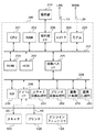
図1は、本発明の実施の形態に係る画像形成システムを示すブロック図である。
【0031】
図1において、画像入力装置である白黒原稿の読取り可能な白黒スキャナ(B/W Scanner)100とカラー原稿の読取り可能なカラースキャナ(Color Scanner)110、画像出力装置(画像形成装置)である低速白黒プリンタ(B/W 20opm Printer)120と中速白黒プリンタ(B/W 40opm Printer)130と高速両面白黒プリンタ(B/W 60opm Printer)140とカラープリンタ(Color 10ppm Printer)150、オフラインでプリント用紙の後処理が可能なオフラインフィニッシャ(Offline Finisher)160、大容量ストレージを有するサーバコンピュータ(Server Computer)170、個人ユーザ向けのパーソナルコンピュータ(Personal Computer)180などがイーサネット(登録商標)(Ethernet(登録商標))などのLAN10に接続されて画像形成システム1が構成されている。この画像形成システム1において、白黒スキャナ100と低速白黒プリンタ120とは白黒専用ビデオバス(Local Video Bus)11によって接続されている。また、カラースキャナ110とカラープリンタ150とはカラー専用ビデオバス(Local Video Bus)12によって接続されている。尚、本形態では、白黒スキャナ100とイメージコントローラ200と白黒プリンタ120(或いは、140)とオンラインフィニッシャ124(或いは、134)のこれらのユニットは、例えば白黒複写機等の画像形成装置として機能すべく、一体型の構成でも良いし、別体型の構成でも良い。同様に、カラースキャナ110とイメージコントローラ200とカラープリンタ150とオンラインフィニッシャ154とは、例えばカラー複写機等の画像形成装置として機能すべく、一体型の構成でも良いし、別体型の構成でも良い。何れの場合も本願発明を適用出来る。
【0032】
白黒スキャナ100及びカラースキャナ110の夫々には、画像読み取り制御及び画像転送制御を行う画像制御装置(Image Controller)200が専用バス(図示せず)により接続されている。
【0033】
低速白黒プリンタ120、中速白黒プリンタ130、高速両面白黒プリンタ140、及びカラープリンタ150の夫々には、プリントした記録紙の後処理をオンラインで指示できるオンラインフィニッシャ(Online Finisher)124,134,144,154が接続されている。
【0034】
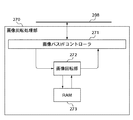
図2は、図1における画像制御装置200の構成を示すブロック図である。
【0035】
図2において、画像制御装置(Controller Unit)200は画像情報やデバイス情報の入出力を行う装置である。画像制御装置(Controller Unit)200は白黒スキャナ100や低速白黒プリンタ120に接続されており、フィニッシャ124を含むスキャナ100及びプリンタ120等の各種ユニットの全体的な制御を司り、後述する図20のフローチャートの処理を含む各種の処理を実行する。また、LAN10や公衆回線(WAN)20にも接続されている。これにより、LAN10やWAN20等を介して入力された外部装置からのデータ(画像情報やデバイス情報等を含む)も処理することができる。
【0036】
CPU201はシステム全体を制御するコントローラである。RAM202はCPU201が動作するためのシステムワークメモリであり、画像データを一時的に記憶するための画像メモリも兼ねている。ROM203はブートROMであり、システムのブートプログラム(後述する図20のフローチャートの処理を含む各種の処理を実行する為のプログラムも含む)が格納されている。HDD204はハードディスクドライブであり、システムソフトウェアや画像データなどが格納されている。また、このHDD204には、ネットワーク(LAN10)に接続されているノードに関する画像出力速度、設置位置などの情報がアドレス毎に保存されている。
【0037】
操作部I/F206は操作部(User Interface)210に接続するためのインターフェース部であり、画像データを操作部210に出力する。この画像データに基づいて操作部210に画像が表示される。本システムの使用者が操作部210から入力した情報がこの操作部I/F206を介してCPU201に伝えられる。
【0038】
ネットワーク209はLAN10に接続されており、情報の入出力を行う。モデム220は公衆回線20に接続されており、この公衆回線20を介して情報の入出力を行う。以上のデバイスはシステムバス207上に配置されている。
【0039】
画像バスI/F205は、画像データを高速で転送する画像バス208とシステムバス207とを接続しており、データ構造を変換するバスブリッジである。画像バス208は、具体的にはPICバスなどの高速バスによって構成される。
【0040】
画像バス208上には以下の各種デバイスが配置されている。ラスターイメージプロセッサ(RIP)230はPDLコードをビットマップイメージに展開するものである。デバイスI/F部240は、画像制御装置200と白黒スキャナ100や低速白黒プリンタ120とを接続し、画像データの同期系/非同期系の変換を行う。スキャナ画像処理部250は入力画像データに対して補正、加工、編集などを行う。プリンタ画像処理部260はプリント出力画像データに対してプリンタの補正、解像度変換などを行う。画像回転部270は画像データの回転を行う。画像圧縮部280は多値画像データをJPEGに圧縮伸張処理し、2値画像データをJBIG、MMR、MHに圧縮伸張処理する。
【0041】
図3は、図2における白黒スキャナ100の概略を示す側面図である。
【0042】
白黒スキャナ100は読み取る原稿をフィードするための原稿フィーダ101を備えている。この原稿フィーダ101はフィードする原稿をセットするためのトレイ102を有している。白黒スキャナ100は画像の描かれた原稿に光を照射しながらCCDライセンサ(図示せず)で原稿を走査することによって原稿から画像情報を読み取り、読み取った画像情報をラスターイメージデータ30として電気信号に変換する。ユーザが操作部210(図2参照)を操作して、原稿を読み取るための指示を出すと、画像制御装置200のCPU201がその指示をスキャナ100に送る。指示を受けたスキャナ100は、原稿フィーダ101によって原稿を1枚ずつフィードしながら原稿上の画像の読取りを実行する。
【0043】
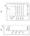
図4は、図2における低速白黒プリンタ120の概略を示す概略斜視図であり、(a)は低速白黒プリンタ120に接続されているフィニッシャを示す斜視図であり、(b)は低速白黒プリンタ120の本体を示す斜視図である。
【0044】
低速白黒プリンタ120は、ラスターイメージデータ40(図2参照)を記録紙上に画像として形成する。この画像形成の方式として、感光体ドラムや感光体ベルト(いずれも図示せず)を用いた電子写真方式、微少ノズルアレイからインクを吐出して記録紙上に直接に画像を印字するインクジェット方式等がある。
【0045】
プリント動作の起動は、CPU201からの指示(ラスターイメージデータ40)によって開始される。低速白黒プリンタ120の内部には、記録紙のサイズや記録紙の向きを選択できるように複数の給紙段が設けられており、これらに対応した複数の給紙カセット122a,122b,122c,122dが装着されている(b)。また、排紙トレイ123は、印字が終了した記録紙を受けるものである。(a)に示すように低速白黒プリンタ120にフィニッシャ124が装着されている場合は、印字された記録紙はフィニッシャ124に搬送される。フィニッシャ124にはステイプラユニット125(後処理ユニット)が装着されている。このステイプラユニット125によって記録紙を50枚単位で綴じたり、100枚単位で綴じたりできる。
【0046】
フィニッシャ124には不図示のインサートトレイを有するインサータユニット126が装着されている。このインサータユニット126は給紙カセット122a,122b,122c,122dのように一つの給紙段として使用できる。インサータユニット126はフィニッシャ124に装着されているため、インサータユニット126のインサートトレイから給紙される用紙(例えば、表紙や合紙や裏表紙、色紙等)は低速白黒プリンタ120内の画像形成部や定着器(いずれも図示せず)などを通過させずにフィニッシャ124内に送り込むことができる。したがって、このインサータユニット126からの用紙(予め印刷が施されているシート等)には印字(画像形成)を行わないが、低速白黒プリンタ120から生じる熱による影響を受けずに(品質が変化すること無く)用紙をプリンタ部120からの印字済みの記録紙の間に挿入(組むこと)できる。また、インサータユニット126にカラープリント済みの原稿などをセットしておくことによってカラー混在の排紙(出力)がフィニッシャ124においてでき、これらを1つ束としてまとめるべく、ステイプルや製本処理することができる。
【0047】
記録紙の両面に印字する場合は、片面を印字した後に低速白黒プリンタ120内で記録紙を反転させる。その後、CPU201からの指示(ラスターイメージデータ40)に従い、まだ印字されていない面を印字する。
【0048】
次に、デバイスI/F240について説明する。
【0049】
図5は、図2のデバイスI/F240の構成を示すブロック図である。
【0050】
図5において、デバイスI/F240に備えられた画像バスI/Fコントローラ241が画像バス208に接続されており、画像バス208のバスアクセスシーケンスを制御する。また、この画像バスI/Fコントローラ241は、以下に述べるデバイスI/F240内の各デバイスを制御すると共に外部のスキャナ100及び低速白黒プリンタ120に制御信号を送信する。
【0051】
スキャンバッファ242は、スキャナ100から送られてきた画像データを一時的に保存すると共にこの保存した画像データを画像バス208に同期させて出力する。シリアルパラレル・パラレルシリアル変換部243は、スキャンバッファ242に保存されている画像データを順番に並べたり、あるいは分解したりして、画像バス208に転送できる画像データのデータ幅に変換する。パラレルシリアル・シリアルパラレル変換部244は、画像バス208から転送されてきた画像データを分解したり、あるいは順番に並べたりして、プリントバッファ245に保存できる画像データのデータ幅に変換する。プリントバッファ245は、画像バス208から送られてきた画像データを一時的に保存すると共にこの保存した画像データをプリンタ120に同期させて出力する。
【0052】
ここで、画像スキャンの処理手順を以下に述べる。スキャナ100から送られてくる画像データを、同じくスキャナ100から送られてくるタイミング信号に同期させて、スキャンバッファ242に保存する。
【0053】
画像バス208がPICバスの場合、バッファ242内に画像データが32ビット以上入ったときは、32ビット分の画像データが先入れ先出しでバッファ242からシリアルパラレル・パラレルシリアル変換部243に送られる。シリアルパラレル・パラレルシリアル変換部243で変換された32ビットの画像データは画像バスI/Fコントローラ241を介して画像バス208上に転送される。また、画像バス208がIEEE1394の場合、バッファ242内の画像データを先入れ先出しでバッファ242からシリアルパラレル・パラレルシリアル変換部243に送られる。シリアルパラレル・パラレルシリアル変換部243で変換されたシリアル画像データは画像バスI/Fコントローラ241を介して画像バス208上に転送される。
【0054】
次に画像プリント時の処理手順を示す。画像バス208がPCIバスの場合、画像バス208から送られてくる32ビットの画像データが画像バスI/Fコントローラ241に受け取られてパラレルシリアル・シリアルパラレル変換部244に送られる。パラレルシリアル・シリアルパラレル変換部244では、画像データはプリンタ120の入力データビット数に分解され、プリントバッファ245に保存される。また、画像バス208がIEEE1394の場合、画像バス208から送られてくるシリアル画像データが画像バスI/Fコントローラ241に受け取られてパラレルシリアル・シリアルパラレル変換部244に送られる。パラレルシリアル・シリアルパラレル変換部244では、画像データはプリンタ120の入力データビット数に変換され、プリントバッファ245に保存される。プリンタ120から送られてくるタイミング信号に同期させて、バッファ245内の画像データは先入れ先出しでプリンタ120に送られる。
【0055】
次に、スキャナ画像処理部250について説明する。
【0056】
図6は、図2のスキャナ画像処理部250の構成を示すブロック図である。
【0057】
図6において、画像バスI/Fコントローラ251が画像バス208に接続されており、画像バス208のバスアクセスシーケンスを制御する。また、画像バスI/Fコントローラ251はスキャナ画像処理部250を構成する下記の各デバイスも制御する。
【0058】
フィルタ処理部252は、空間フィルタでありコンボリューション演算を実行する。編集処理部253は、例えば入力画像データからマーカーペンによるマーカーで囲まれた閉領域を認識して、その閉領域内の画像データに対して、影つけ、網掛け、ネガポジ反転などの各種の画像加工処理を実行する。変倍処理部254は、読取り画像の解像度を変更する場合にラスターイメージの主走査方向について補間演算を行って画像の拡大や縮小を実行する。副走査方向の変倍は、画像読取りラインセンサ(図示せず)の走査速度を変更することによって実行される。テーブル処理部255は、読み取った輝度データである画像データを濃度データにテーブル変換する。2値化処理部256は多値のグレースケール画像データを誤差拡散処理やスクリーン処理によって2値化する。これらの処理が終了した画像データは、再び画像バスI/Fコントローラ251を介して、画像バス208上に転送される。
【0059】
次に、プリンタ画像処理部260について説明する。
【0060】
図7は、図2のプリンタ画像処理部260の構成を示すブロック図である。
【0061】
図7において、画像バスI/Fコントローラ261が画像バス208に接続されており、画像バス208のバスアクセスシーケンスを制御する。また、プリンタ画像処理部260を構成する各デバイスも制御する。各デバイスのうち解像度変換処理部262は、LAN10あるいは公衆回線20を介して受信した画像データをプリンタ120の解像度に変換(解像度変換)する。スムージング処理部263は、解像度変換後の画像データのジャギーを滑らかにする処理を行う。なお、「ジャギー」とは、斜め線や曲線が滑らかな線にならずにギザギザになった線のことである。
【0062】
次に、画像回転処理部270について説明する。
【0063】
図8は、図2の画像回転処理部270の構成を示すブロック図である。
【0064】
図8において、画像バスI/Fコントローラ271が画像バス208に接続されており、画像バス208のバスシーケンスを制御する。また、この画像バスI/Fコントローラ271は画像回転部272にモード等を設定し、画像回転部272に画像データを転送するためのタイミング制御も行う。以下に画像回転部272の処理手順を述べる。
【0065】
画像バス208を介して、CPU201(図2参照)が画像バスI/Fコントローラ271に画像回転制御の設定指示をすると、この設定指示に基づいて画像バスI/Fコントローラ271は画像回転部272に対して画像回転に必要な設定を行う。設定される項目は、例えば、画像サイズ、回転方向、角度などである。設定が終了した後、再度、CPU201が画像バスI/Fコントローラ271に対して画像データ転送の許可を行う。この許可に従って画像バスI/Fコントローラ271はRAM202(図2参照)又は画像バス208上の各デバイスから画像データの転送を開始する。尚、ここでは回転を行う画像サイズを、例えば32×32(bit)とする。また、画像バス208上に画像データを転送させる際に32bitを単位とする画像転送を行うものとする。ここで扱う画像は2値を想定する。
【0066】
上述のような32×32(bit)の画像を得るためには、上述の単位のデータ転送を32回行う必要があり、且つ不連続なアドレスから画像データを転送する必要がある(図10参照)。
【0067】
不連続アドレッシングによって転送された画像データは、読出し時に所望の角度に回転されているようにRAM273に書き込まれる。例えば、反時計方向に90度の回転であれば、最初に転送された32bitの画像データをY方向に書き込んでいく(図11参照)。これを読出し時にはX方向に読み出すことによって画像が回転される。
【0068】
32×32(bit)の画像回転(RAM273への書込み)が完了した後、画像回転部272はRAM273から上述した読出し方法で画像データを読み出し、画像バスI/Fコントローラ271に画像を転送する。
【0069】
回転処理された画像データを受け取った画像バスI/Fコントローラ271は、連続アドレッシングによってRAM202又は画像バス208上の各デバイスにデータを転送する。
【0070】
この一連の処理は、必要なページ数の処理が終了してCPU201からの処理要求が無くなるまで繰り返される。
【0071】
次に、画像圧縮処理部280について説明する。
【0072】
図9は、図2の画像圧縮処理部280の構成を示すブロック図である。
【0073】
図9において、画像バスI/Fコントローラ281が画像バス208に接続されており、画像バス208のバスアクセスシーケンスを制御する。また、入力バッファ282と出力バッファ285との間のデータのやりとりを行うためのタイミング制御及び画像圧縮部283に対するモード設定等の制御も行う。この画像圧縮部283にはRAM284が接続されている。このように構成された画像圧縮処理部280の処理手順は以下のように実行される。
【0074】
CPU201が画像バス208を介して画像バスI/Fコントローラ281に画像圧縮制御のための設定指示を行う。この設定指示により画像バスI/Fコントローラ281は画像圧縮部283に対して画像圧縮に必要な設定を行う。例えば、MMR圧縮やJBIG伸長などの設定である。この設定を行った後に、再度、CPU201が画像バスI/Fコントローラ281に対して画像データ転送の許可を行う。この許可に従い、画像バスI/Fコントローラ281はRAM202又は画像バス208上の各デバイスから画像データの転送を開始する。受け取った画像データは入力バッファ282に一時的に格納し、画像圧縮部283の画像データ要求に応じて一定のスピードで画像を転送する。この際、入力バッファ282は画像バスI/Fコントローラ281と画像圧縮部283との間で画像データを転送できるか否かを判別する。画像バス208からの画像データの読込み及び、画像圧縮部283への画像の書込みが不可能である場合は、データの転送を行わないように制御する。以下、このような制御をハンドシェークと記す。
【0075】
画像圧縮部283は受け取った画像データを、一旦、RAM284に格納する。ここで、一旦、画像データをRAM284に格納する理由は、画像圧縮の際には画像圧縮処理の種類によって数ライン分のデータを必要とするので、最初の1ライン分の圧縮を行う以前に数ライン分の画像データを用意しておく必要があるからである。
【0076】
画像圧縮をされた画像データは直ちに出力バッファ285に送られる。出力バッファ285では、画像バスI/Fコントローラ281と画像圧縮部283との間でハンドシェークが行われ、画像データが画像バスI/Fコントローラ281に転送される。
【0077】
画像バスI/Fコントローラ281は、圧縮(又は伸長)されて転送されて来た画像データをRAM202又は画像バス208上の各デバイスに転送する。この一連の処理は、例えば、必要なページ数の処理が終わったときのようにCPU201からの処理要求が無くなるまで、又は、圧縮時及び伸長時にエラーが発生したときのように画像圧縮部283から停止要求が出るまで繰り返される。
【0078】
以上のように構成された画像形成システムにおいて、スキャナ100やNetwork209から入力された1つ又は複数の画像はドキュメント(文書)として扱われ、ボックスと呼ばれる画像記録エリアに格納できる。ボックス内の画像データや属性データはHDD204に記録される。
【0079】
図12は、図2における操作部210に表示されるコピー基本画面を例示する図である。
【0080】
コピー基本画面300には、様々なコピー機能を使用する場合に押下する応用モードボタン301が表示されている。
【0081】
図13は、図2における操作部210に表示される応用モード画面を例示する図である。
【0082】
応用モード画面400は、コピー基本画面300において応用モードボタン301を押下すると表示される。表紙/合紙ボタン401は画像形成の終了した記録紙に表紙(別紙)を付けたり(組んだり)合紙(別紙)を挿入する(組む)場合に使用する。「表紙+裏表紙」と表示された吹出し402は表紙/合紙ボタン401を押下したときに表示される。この吹出し402は、図15に示す表紙/合紙選択画面600における設定内容の一部が表示される。ここでは、画像形成の終了した記録紙に表紙と裏表紙(別紙)とを付ける設定になっていることが「表紙+裏表紙」の吹出しによって表示されている。
【0083】
図14は、図2における操作部210に表示される給紙段選択画面を例示する図である。
【0084】
図14の表紙/合紙の用紙選択画面500は、図15に示す表紙の用紙選択ボタン602、裏表紙の用紙選択ボタン603、及び合紙章紙の用紙選択ボタン604の何れを押下したときにも表示される。ユーザは、この図14の画面を介して、プリンタが具備する給紙部122の他にインサータユニット126からの給紙を選択することができる。尚、例えば表紙や裏表紙等のシートをインサータユニット126から給紙する場合、プリンタ部を通過せずにフィニッシャ内部にシートを送り込む。従って、インサータユニット126にセットするシートは、予め表紙用の画像や裏表紙用の画像をプリントしたものをセットする。ここでは、インサータ給紙段の選択ボタン501をユーザが押下し、インサータユニット126(図4参照)からの給紙を選択しているものとする。
【0085】
図15は、図2における操作部210に表示される表紙/合紙設定画面の一例を示す図である。
【0086】
表紙/合紙設定画面600は、表紙/合紙の種類と給紙箇所とを選択するための画面であり、表紙/合紙ボタン401を押下したときに表示される。表紙を使用するときは表紙ボタン601を押下し、裏表紙を使用するときは裏表紙ボタン605を押下し、合紙を使用するときは合紙ボタン606を押下し、章紙(別紙)を使用するときは章紙ボタン607を押下する。これらのボタンがユーザにより押下されると、夫々の給紙段が選択できる。表紙ボタン601を押下してから表紙の用紙選択ボタン602を押下すると、不図示の給紙部選択画面ウインドウが表示され、表紙の給紙段として、プリンタ部の給紙部122及びインサータユニット126を含む複数の給紙部の候補の中から所望の給紙部を選択できる。裏表紙ボタン605を押下してから裏表紙の用紙選択ボタン603を押下すると、不図示の給紙部選択画面ウインドウが表示され、裏表紙の給紙段として、プリンタ部の給紙部122及びインサータユニット126を含む複数の給紙部の候補の中から所望の給紙部を選択できる。合紙ボタン606を押下してから合紙章紙の用紙選択ボタン604を押下すると、不図示の給紙部選択画面ウインドウが表示され、合紙章紙の給紙段として、プリンタ部の給紙部122及びインサータユニット126を含む複数の給紙部の候補の中から所望の給紙部を選択できる。これらの選択の後にOKボタン608を押下すると設定が完了する。
【0087】
図16は、図2における操作部210に表示される表紙/合紙設定画面の別の例を示す図である。
【0088】
表紙/合紙設定画面700では表紙ボタン701と裏表紙ボタン703とが押下されている。さらに、表紙の用紙選択ボタン702と裏表紙の用紙選択ボタン704との操作によって共にインサータユニット126が給紙段として選択されている。このように、本形態では、図15の例のような設定をユーザがした場合、1つの出力結果としてのシート束の中に、インサータユニット126からシートを1枚だけ挿入させることもできるし、また、図16の例のような設定をした場合、1つのシート束の中に、例えば、表紙と裏表紙等、複数枚のシートをインサータユニット126から挿入させることもできるようにし、これらをユーザが選択可能に構成している。尚、図14、図15、図16等の設定画面を介してユーザにより設定された情報は、ジョブ情報として、例えば、後述する図21に示すようなテーブル形式でコントローラ200により各ジョブ毎に管理される。そして、コントローラ200は、これらの情報等に基づいて、スキャナ100やプリンタ部120やフィニッシャ124やインサータユニット126等の各種ユニット動作を制御する。
【0089】
図17は、コピー中に図2における操作部210に表示されるコピー実行画面を例示する図である。
【0090】
図14乃至図16等の設定画面を介し各種の出力ジョブ設定が済み、操作部210のスタートキー(図示せず)を押下すると、コピージョブが始まって原稿の読込みが開始され、コピー実行画面800が表示される。コピー実行画面に重なって表示されている画面は、コピージョブの進行状況を表示するコピーダイアログ801である。
【0091】
図18は、図2における操作部210に表示されるジャム画面を例示する図である。
【0092】
ジャム画面900は、コピージョブの実行中にジャム(紙詰まり)が発生した場合に表示される。
【0093】
図19は、ジャムが発生して図18のジャム通知を行い、その後、ユーザにより紙詰りが除去されたことを検知した後に、図2における操作部210に表示されるリカバリー画面を例示する図である。
【0094】
リカバリー画面1000は、インサータユニット126からの給紙中にジャムが発生した場合に表示されることがある。リカバリー指示ダイアログ1001はユーザに対する指示を表示する。プリント再開ボタン1003はジャムを起こしたジョブを再開させる場合に押下する。即ち、ジャムリカバリーの実行指示をユーザがマニュアル指示する。
【0095】
次に、図20及び図21を参照しながらジャムが発生したときの処理について説明する。
【0096】
図20は、ジャムが発生したときの処理を示すフローチャートである。この処理を実行する為のプログラムはROM203等のメモリに格納されており、イメージコントローラ200により読出し実行される。
【0097】
図21は、給紙管理テーブルを例示する図である。
【0098】
給紙管理テーブル1100はジョブ毎に設けられるものであり、ジョブ中の給紙段の仕様設定情報が格納されている。この例においては、本文1101、表紙1102、裏表紙1103、合紙1104はそれぞれ1105,1106,1107,1108に対応付けられている。この例によれば、ジョブ1、ジョブ2・・・ジョブNの計N個のジョブが出力すべきジョブとして登録されている。ジョブ2の給紙管理情報は1100−1で、ジョブ2の給紙管理情報は1100−2で、ジョブNの給紙管理情報は1100−Nである。
【0099】
ジョブ1の給紙情報に関しては、本文1101−1の給紙段は自動用紙給紙段であり、表紙1102−1はインサータユニットであり、裏表紙1103−1はプリンタ部が有すカセット1である。また、合紙1104−1は使用しないので「なし」となっている。即ち、ジョブ1はインサータからシートを1枚だけ給紙するジョブである。
【0100】
ジョブ2の給紙情報に関しては、本文1101−2の給紙段はプリンタ部が有するカセット1であり(即ち、スキャナ100により読取った本文原稿画像をプリントする為のシートとしてカセット1のシートを使用することを意味する)、表紙1102−2はインサータユニットであり(表紙としてインサータユニット126にセットされたシートを使用することを意味する)、裏表紙1103−2もインサータユニットであり(裏表紙としてインサート126にセットされたシートを使用することを意味する)、合紙1104−1はプリンタ部が有すカセット2である(合紙としてカセット2のシートを使用する)。即ち、ジョブ2はインサータから複数枚のシート(表紙と裏表紙の2枚分)を給紙するジョブである。
【0101】
ジョブNの給紙情報に関しては、本文1101−Nの給紙段としてプリンタ部が有するカセット1を使用し、表紙1102−Nは「なし」であり(表紙は使わない)、裏表紙1103−Nも「なし」であり(裏表紙も使わない)、合紙1104−Nも「なし」である(合紙も使用しない)。即ち、ジョブNはインサータからシートを給紙しないジョブ(インサータを使用しないジョブ)である。
【0102】
ジョブ中にジャムが発生したときは、図20に示すように先ず、ステップS5001でジャム画面900を操作部210に表示してユーザにジャムの発生を知らせると共にジャムを起こしている紙(ジャム紙)の除去をユーザに促す。この後、ジャム紙が除去されてジャムが解消されるまで待機する(ステップS5002)。ジャムが解消されたか否かの判断(シートが除去されたか否かの判断)は、画像形成装置本体及びフィニッシャ内部のシート搬送路に設けられたシート有無を検知する為のセンサからの検出結果等に基づく。ジャムが解消されるとジャム画面900を消して(ステップS5003)、コピー実行画面800を操作部210に表示する。
【0103】
次にジョブにおける給紙段の使用の解析を判別する(ステップS5004)。即ち、図21に示した給紙管理テーブル1100に基づいて、ジョブがインサータユニット126を給紙段として使用するか否かを判別する。ここで、ジョブがインサータユニット126を使用する場合とは、給紙管理テーブル1100の1105,1106,1107,1108に一つでもインサータユニット126の指定がある場合をいう。ジョブがインサータユニット126を使用する場合は、次のステップS5005に進む。例えば、図21の例を用いて説明すると、図21のジョブ1やジョブ2は、インサータユニット126を使用するジョブに該当する。従って、これら何れかのジョブにてジャムが発生した場合はステップS5005へ移行する。一方、ジョブNはインサータユニット126を使用しないジョブである。従って、このジョブNにてジャムが発生した場合は、ステップS5008へと移行する。
【0104】
ステップS5005では、当該ジョブが1部の束に対して複数の用紙をインサータユニット126から給紙するジョブか否かを判別する。複数の用紙をインサータユニット126から給紙する場合、例えば、図16に示した設定例のように1105,1106,1107,1108のうち2つ以上にインサータユニット126の指定がある場合は、ユーザにインサータ用紙の再点検を促すために、図19に示すようなリカバリー指示ダイアログ1001を表示する(ステップS5006)。例えば、図21の例を用いて説明すると、図21のジョブ1の場合、インサータユニット126からは1枚しかシートを給送しない。即ち、1部の束に対して複数の用紙をインサータユニット126から給紙するジョブではないので、ジョブ1にてジャムが発生した場合、ステップS5008へと移行する。一方、図21のジョブ2の場合は、インサータユニット126から2枚シートを給送する。即ち、当該ジョブが1部の束に対して複数の用紙をインサータユニット126から給紙するジョブであるので、ジョブ2にてジャムが発生した場合、ステップS5006へと移行する。
【0105】
次に、ユーザからの指示を待ち(ステップS5007)、プリント再開ボタン1003(図19)が押下されたときは、ジャムリカバリー処理を実行し、中断していたジョブを再開した後に本処理を終了する(ステップS5008)。尚、ステップS5008におけるリカバリー動作としては、例えば、5頁からなる原稿束を先頭ページから順にプリントする場合において、3頁目の原稿のプリントを行ったシートがジャムとなった場合、リカバリー動作として、3頁目の原稿のプリントから処理を再開する。尚、どのページにおいてジャムが発生したかを確認する方法としては、操作部から入力されたユーザからの設定情報や、画像形成装置の排紙部に設けられた排出枚数をカウントする(出力が完了したシートの枚数をカウントする)為のカウンターからの情報等に基に判別する。又、例えば、パンフレットモード等の製本処理では、画像の入力順序と実際にシートにプリントする画像の出力順序とが異なる(頁順序が入れ替えられてプリントされる)。故に、このような画像形成動作を実行している場合においてジャムが発生した場合、リカバリー動作としては、例えば、1頁目のプリントから処理をやり直す。複数部出力の場合は、部の切れ目から処理を再開する。又、例えば、1ジョブ内で本文原稿に対してインサータユニット126からのシートを挿入する画像形成動作においてジャムが発生した場合に、ジャム対象のシートがインサータユニット126からのシートの場合、リカバリー動作としては、例えば、インサータユニット126からシートを給送する動作から処理を再開する。インサータユニット126からのシートがジャムしたかどうかは、例えば、図14、15、16等の操作画面を介して入力されたユーザからの設定情報や、インサータユニット126からのシートが搬送されるパス上のセンサからの情報等に基づいて判断する。以上のような処理が、ステップS5008においてリカバリー処理として実行される。
【0106】
ステップS5004の判別の結果、ジョブがインサータユニット126を使用しない場合は、上記したステップS5005からステップS5007までの各ステップを経ずにステップS5008に進んで本処理を終了する。ここで、ジョブがインサータユニット126を使用しない場合とは、給紙管理テーブル1100の1105,1106,1107,1108のいずれにもインサータユニット126の指定が無い場合をいう。例えば、図21の例を用いて説明すると、ジョブNがそれに該当する。
【0107】
ステップS5005の判別の結果、インサータユニット126から給紙される用紙が複数でない場合、例えば、図15に示した設定例のように1105,1106,1107,1108のうち1つだけにインサータユニット126の指定がある場合は、ステップS5008に進んで本処理を終了する。例えば、図21の例を用いて説明すると、ジョブ2がそれに該当する。
【0108】
図20の処理によれば、ジャム画面900を操作部210に表示してユーザにジャムの発生を知らせると共にジャムを起こしている紙(ジャム紙)の除去を促す(ステップS5001)。ジャムが解消された後は、給紙管理テーブル1100に基づいて、ジョブがインサータユニット126を使用し(ステップS5004でYES)、且つ、当該ジョブが1部の束に対して複数の用紙をインサータユニット126から給紙するジョブである(ステップS5005でYES)場合に、ユーザにインサータ用紙の再点検を促すために、リカバリー指示ダイアログ1001を表示する(ステップS5006)。ユーザからの指示によってジャムリカバリー処理を実行し、中断していたジョブを再開した後に本処理を終了する(ステップS5008)。これにより、ユーザは、ジャムリカバリー処理後のジョブを再開する前に、ジョブの再開後に給紙されるべき用紙を確認できるので、確実に正しく用紙を給紙できる。このように、本形態では、シートジャムの発生等に起因して画像形成動作が中断されたジョブのリカバリー動作を行うにあたり、処理が中断されたジョブがインサータユニット126を使用するジョブで且つインサータユニット126から2枚以上シートを給送させるジョブの場合は、図19に示すような表示を操作部に行い、ユーザにインサータユニット126のチェックを通知する。そして、図19の画面1001内のプリント再開ボタン1003がユーザにより押下されたことに応じて、リカバリー動作を実行するよう制御する。即ち、自動的にリカバリー処理を行うことを禁止して、ユーザからの指示により、リカバリー動作を開始するよう制御する(ユーザからの指示によりリカバリー動作を開始するモード)。一方、中断対象のジョブが、インサータユニット126を使用しないジョブの場合、又は、インサータユニット126からの1枚だけシートを給送するジョブの場合は、図19のような通知をユーザに対して実行することなく、自動的にリカバリー処理を実行するよう制御する。即ち、ユーザに対する通知処理を禁止して、自動的にリカバリー動作を開始するよう制御する(ユーザからの指示なしにリカバリー動作を開始するモード)。
【0109】
尚、上述の形態では、インサータユニット126からシートを1枚給送するか、複数枚給送するかによって、制御を切り換えている。これは、以下のような各種の状況を考慮しているからである。例えば、複数部数分の印刷を行うもので、1部の束の中に、インサータユニット126から表紙と裏表紙の2枚のシートを給送する処理の場合、インサータには、表紙と裏表紙が複数部数分順番にセットされる。このような状況下で、例えば、リカバリー動作として、インサータユニット126からのシートの給送動作から処理を自動的に再開してしまったら、表紙を挿入すべきところに裏表紙としてのシートが挿入されてしまう等、インサート紙の挿入順序が狂ってしまう不具合等が生じる可能性がある。それ故、本形態では、中断対象のジョブが、1部の束の中に、インサータユニット126から複数枚シートを給送させるジョブの場合は、自動的にリカバリー動作を実行せずに、ユーザからの指示によりリカバリー動作を開始するよう制御する。一方、1部の束の中に、インサータユニット126から表紙等、1枚だけ給送する処理の場合は、上述のような不具合が生じることがないので、ユーザからの指示なしにリカバリー動作を開始させる。
【0110】
又、上述の形態では、1部の束に対して、インサータユニット126からシートを1枚給送する場合と、複数枚給送する場合とでリカバリー方法を変えているが、中断対象のジョブが、インサータユニット126からシートを1枚給送するジョブであるか複数枚給送するジョブであるかを判断する処理等(ステップS5005の処理等)を簡略化するべく、以下のような構成でも本願発明は適用可能である。
【0111】
例えば、中断されたジョブのリカバリー動作を行うにあたり、中断対象のジョブが、インサータユニット126を使用するジョブであることに応じて、インサータからのシートの枚数は関係なく、図19に示すような表示を操作部に行い、ユーザにインサータユニット126のチェックを促し、図19の画面1001内のプリント再開ボタン1003がユーザにより押下されたことに応じて、リカバリー動作を実行するよう制御する(即ち、ユーザからの指示によりリカバリー動作を開始するモードを行う)。例えば、図21の例を用いると、ジョブ1とジョブ2がこれに該当する。一方、中断対象のジョブが、インサータユニット126を使用しないジョブであることに応じて、図19のような通知をユーザに対して実行することなく、自動的にリカバリー処理を実行するよう制御する(ユーザからの指示なしにリカバリー動作を開始するモードを行う)。図21の例を用いれば、ジョブNがこれに該当する。尚、この形態の処理を実行する為のフローチャートは、図20のフローチャートのステップS5004の判断でYESなら、そのままステップS5006以降の処理へ移し、ステップS5004の判断でNOならステップS5008へ移すような構成であれば良い。このように処理することで上述の不具合が発生することも無く、装置の構成を簡略化することができる。
【0112】
又、別の形態としては、中断対象のジョブが、如何なるジョブであっても、自動的にリカバリー処理をせずに、ユーザに通知するような構成でも良い。但し、この場合でも、中断対象のジョブが如何なるジョブであるかによって、通知内容を異ならせるよう制御する。例えば、中断対象のジョブが、インサータユニット126を使用するジョブ(図21の例だと、ジョブ1やジョブ2)であることに応じて、図22(a)のような表示を行う。一方、インサータユニット126を使用するジョブ(図21の例だとジョブN)でないことに応じて、図22(b)のような表示を行うよう制御する。
【0113】
又、別の形態として、中断対象のジョブが、インサータユニット126を使用するジョブで且つインサータユニット126から2枚以上シートを給送させるジョブの場合(図21の例だとジョブ2の場合)に図22(a)のような表示を行う。一方、インサータユニット126を使用しないジョブや、インサータユニット126から1枚だけシートを給送するジョブの場合(図21の例だとジョブ1やジョブNの場合)、図22(b)のような表示を行うよう制御しても良い。
【0114】
又、上述の各種の形態では、シートジャムが発生して場合におけるリカバリー動作について説明したが、原稿フィーダにおける原稿ジャムによるジョブの中断の場合や、フィニッシャ124におけるステイプルユニット(不図示)のステイプルジャムによるジョブの中断の場合における、リカバリー動作についても本願発明は適用可能である。何れの場合も、装置内部に設けられた各種のセンサからの情報に基づいて、ジョブを中断し、ユーザによりジョブ中断の原因が除去されたことを確認したら、上述のリカバリー動作の制御を行う。
【0115】
又、図2のLAN10やWAN20を介して入力された外部装置からのデータを処理する場合でも本願発明は適用可能である。この場合、例えば、コンピュータ上に、図13〜図19及び図22に示す各種の操作画面を表示可能に構成し、図14〜図16等の画面を介してコンピュータ上にてインサータユニット126に対する設定をユーザにより実行させ、これらの設定情報を、画像データとともにプリンタ側に送信し印刷処理を実行させる。そして、ジャムが発生したら、プリンタ側からPC側にその情報を送信し、図18の表示をPC上で実行させ、ユーザによりジャムが除去されたら、上述の形態と同様に、中断対象のジョブ如何によって、図19や図22の表示をPC上で実行させる。そして、ボタン1003が押下されたことにより、プリンタ側で処理を再開させるよう制御する。
【0116】
なお、上記処理は画像制御装置において実行されるものとして説明したが、画像形成装置の制御部(図示せず)が上記処理を実行してもよい。
【0117】
また、上記処理方法を記憶した任意の記憶媒体が、画像制御装置又は画像形成装置の制御部に上記処理方法を実行するプログラムを供給し、画像制御装置のCPU又は不図示のMPUの何れか1つが上記プログラムを実行するようにしてもよい。あるいは、上記記憶媒体が、画像形成装置の制御部に上記プログラムを供給し、画像形成装置の不図示のCPU又はMPUの何れか1つが上記プログラムを実行するようにしてもよい。上記記憶媒体としては、例えば、RAM、NV−RAM、フロッピー(登録商標)ディスク、ハードディスク、光ディスク、光磁気ディスク、CD−ROM、MO、CD−RW、DVD(DVD−ROM、DVD−R)、磁気テープ、不揮発性のメモリカード、他のROM等がある。
【0118】
また、画像制御装置のCPU又はMPUのいずれか1つの代わりに、これらと同様の動作をする不図示の回路が上述した実施の形態を実現してもよい。あるいは、画像形成装置の制御部のCPU又はMPUのいずれか1つの代わりに、これらと同様の動作をする不図示の回路が上述した実施の形態を実現してもよい。
【0119】
また、記憶媒体が供給する上記プログラムは、画像制御装置に挿入された不図示の機能拡張ボードや画像制御装置に接続された不図示の機能拡張ユニットに備わる不図示のメモリに書き込まれた後に、その機能拡張ボードや機能拡張ユニットに備わる不図示のCPU等が上記プログラムの一部又は全部を実行してもよい。あるいは、記憶媒体が供給する上記プログラムは、画像形成装置に挿入された不図示の機能拡張ボードや画像形成装置に接続された不図示の機能拡張ユニットに備わる不図示のメモリに書き込まれた後に、その機能拡張ボードや機能拡張ユニットに備わる不図示のCPU等が上記プログラムの一部又は全部を実行してもよい。
【0120】
【発明の効果】
以上詳細に説明したように、請求項1記載の画像形成システム、請求項2記載の画像形成システムの制御方法、請求項3記載の記憶媒体、請求項4記載の画像形成装置、請求項5記載の画像形成装置の制御方法、請求項6記載の記憶媒体によれば、紙詰まりが発生したジョブが複数種類の別紙が組まれたジョブである場合に、紙詰まりの発生情報を表示させ、且つ、別紙の状態の確認を指示する表示を実行させ、紙詰まりが発生したジョブが1種類の別紙のみが組まれたジョブである場合に、紙詰まりの発生情報は表示させるが、別紙の状態の確認を指示する表示は実行させないようにするので、画像形成の終了した記録紙に組まれる別紙の種類の数に対応して、ユーザは必要な処置を行える。この結果、給紙されるべき用紙が正しく給紙できることとなる。
【0121】
また、請求項7記載の画像形成システム、請求項9記載の画像形成システムの制御方法、請求項14記載の記憶媒体によれば、上述と同様の効果を得ることが出来る。
【図面の簡単な説明】
【図1】本発明の実施の形態に係る画像形成システムの構成を示すブロック図である。
【図2】図1における画像制御装置200の構成を示すブロック図である
【図3】図2における白黒スキャナ100の概略を示す側面図である。
【図4】図2における低速白黒プリンタ120の概略を示す側面図であり、(a)は低速白黒プリンタ120に接続されているフィニッシャを示す斜視図であり、(b)は低速白黒プリンタ120の本体を示す斜視図である。
【図5】図2のデバイスI/F240の構成を示すブロック図である。
【図6】図2のスキャナ画像処理部250の構成を示すブロック図である。
【図7】図2のプリンタ画像処理部260の構成を示すブロック図である。
【図8】図2の画像回転処理部270の構成を示すブロック図である。
【図9】図2の画像圧縮処理部280の構成を示すブロック図である。
【図10】画像回転を説明する図である。
【図11】画像回転の方法を示す図である。
【図12】図2における操作部210に表示されるコピー基本画面を例示する図である。
【図13】図2における操作部210に表示される応用モード画面を例示する図である。
【図14】図2における操作部210に表示される給紙段選択画面を例示する図である。
【図15】図2における操作部210に表示される表紙/合紙設定画面の一例を示す図である。
【図16】図2における操作部210に表示される表紙/合紙設定画面の別の例を示す図である。
【図17】コピー中に図2における操作部210に表示されるコピー実行画面を例示する図である。
【図18】図2における操作部210に表示されるジャム画面を例示する図である。
【図19】ジャムが発生して図18のジャム通知を行い、その後、ユーザにより紙詰りが除去されたことを検知した後に、図2における操作部210に表示されるリカバリー画面を例示する図である。
【図20】ジャムが発生したときの処理を示すフローチャートである。
【図21】給紙管理テーブルを例示する図である。
【図22】ジョブが中断されたときに、中断されたジョブの種類に応じて表示される画面を示す図であり、(a)はインサータユニット126を使用するジョブであることに応じて表示される画面を示す図であり、(b)はインサータユニット126を使用するジョブでないことに応じて表示される画面を示す図である。
【符号の説明】
1 画像形成システム
10 イーサネット(登録商標)(ネットワーク)
100 白黒スキャナ
110 カラースキャナ
120 低速の白黒プリンタ(画像形成装置)
124 フィニッシャ
125 ステイプラユニット(後処理ユニット)
126 インサータユニット
130 中速の白黒プリンタ(画像形成装置)
140 高速の両面白黒プリンタ(画像形成装置)
150 カラープリンタ(画像形成装置)
200 画像制御装置
210 操作部[0001]
BACKGROUND OF THE INVENTION
The present invention relates to an image forming system, a control method thereof, an image forming apparatus, a control method thereof, and a recording medium storing a program for executing the control method.
[0002]
[Prior art]
Conventionally, in an image forming system such as a copying machine or a printer, only a cover sheet is fed from an inserter.
[0003]
[Problems to be solved by the invention]
If cover sheets, slip sheets, and back cover sheets can be fed from the inserter, multiple different types of separate sheets (cover sheet, slip sheet, and back cover sheet) are placed on one inserter (feed stage). Will be placed. For this reason, when recovering a job that has been interrupted due to the occurrence of a jam (paper jam) or the like and feeding paper, there is a possibility that the paper to be fed next will not be fed correctly.
[0004]
SUMMARY OF THE INVENTION An object of the present invention is to execute an image forming system, a control method thereof, an image forming apparatus, a control method thereof, and these control methods capable of correctly feeding a sheet to be fed next when a jam occurs. It is to provide a recording medium storing a program.
[0005]
[Means for Solving the Problems]
In order to achieve the above object, an image forming system according to claim 1 controls an image forming apparatus including a separate sheet setting unit that forms at least one type of separate sheet on a recording sheet on which image formation has been completed, and the image forming apparatus. In an image forming system having an image control device, the image control device includes:Paper jam display means for detecting a paper jam and displaying paper jam occurrence information, and a separate paper discrimination means for judging whether the job in which the paper jam has occurred is a job in which a plurality of types of different papers are assembled by the separate paper setting means. When the job in which the paper jam has occurred is a job in which a plurality of types of separate sheets are combined, the display means displays the information on occurrence of the paper jam by the display means, and displays the display for instructing the confirmation of the status of the separate sheet. When the job in which the paper jam occurs is a job in which only one type of separate paper is assembled, the information on the occurrence of paper jam is displayed by the display means, but a display for instructing confirmation of the status of the separate paper Comprises a display change means for preventing the display means from executing the display change means.It is characterized by that.
[0007]
In order to achieve the above object, the claims2The image forming system control method described above includes an image forming apparatus that includes a separate sheet setting unit that assembles at least one type of separate sheet on a recording sheet on which image formation has been completed, and an image forming apparatus that controls the image forming apparatus. In the control method of the image forming system executed by the image control device of the system,A display step for detecting a paper jam and displaying the occurrence information of the paper jam on the display means, and a separate paper discrimination for judging whether the job in which the paper jam has occurred is a job in which a plurality of types of different papers are combined by the separate paper setting means. When the job in which the paper jam has occurred is a job in which a plurality of types of separate papers are assembled, the information indicating the occurrence of paper jam is displayed by the display means, and the display for instructing the confirmation of the state of the separate paper is When the job that is executed by the display means and the paper jam occurs is a job in which only one type of separate paper is assembled, the information on occurrence of paper jam is displayed by the display means, but the confirmation of the status of the separate paper is instructed. A display changing step for preventing display from being executed by the display means.It is characterized by that.
[0009]
In order to achieve the above object, the claims3The recording medium described above includes the image forming apparatus including an image forming apparatus including a separate sheet setting unit that assembles at least one type of separate sheet on a recording sheet on which image formation has been completed, and an image control apparatus that controls the image forming apparatus. A readable storage medium storing a program for executing a control method of an image forming system executed by a control device, wherein the program isA display module for detecting a paper jam and displaying the occurrence information of the paper jam on the display unit, and a separate sheet for determining whether the job in which the paper jam has occurred is a job in which a plurality of types of different sheets are combined by the separate sheet setting unit When the discrimination module and the job in which the paper jam has occurred are jobs in which a plurality of types of separate papers are assembled, the information indicating the occurrence of the paper jam is displayed by the display means, and a display for instructing the confirmation of the status of the separate paper is displayed. When the job that has been executed by the display means and the paper jam has occurred is a job that includes only one type of separate paper, the information on the occurrence of paper jam is displayed by the display means, but the confirmation of the status of the separate paper is instructed. A display change module for preventing the display to be executed by the display means.It is characterized by that.
[0010]
In order to achieve the above object, the claims4The image forming apparatus described above includes an additional sheet setting unit configured to assemble at least one type of separate sheet on a recording sheet on which image formation has been completed.Paper jam display means for detecting a paper jam and displaying paper jam occurrence information, and a separate paper discrimination means for judging whether the job in which the paper jam has occurred is a job in which a plurality of types of different papers are assembled by the separate paper setting means. When the job in which the paper jam has occurred is a job in which a plurality of types of separate sheets are combined, the display means displays the information on occurrence of the paper jam by the display means, and displays the display for instructing the confirmation of the status of the separate sheet. When the job in which the paper jam occurs is a job in which only one type of separate paper is assembled, the information on the occurrence of paper jam is displayed by the display means, but a display for instructing confirmation of the status of the separate paper Comprises a display change means for preventing the display means from executing the display change means.It is characterized by that.
[0012]
In order to achieve the above object, the claims5The control method of the image forming apparatus described in the above method is the control method of the image forming apparatus provided with a separate sheet setting unit for assembling at least one type of separate sheet on the recording sheet on which image formation has been completed.A display step for detecting a paper jam and displaying the occurrence information of the paper jam on the display means, and a separate paper discrimination for judging whether the job in which the paper jam has occurred is a job in which a plurality of types of different papers are combined by the separate paper setting means. When the job in which the paper jam has occurred is a job in which a plurality of types of separate papers are assembled, the information indicating the occurrence of paper jam is displayed by the display means, and the display for instructing the confirmation of the state of the separate paper is When the job that is executed by the display means and the paper jam occurs is a job in which only one type of separate paper is assembled, the information on occurrence of paper jam is displayed by the display means, but the confirmation of the status of the separate paper is instructed. A display changing step for preventing display from being executed by the display means.It is characterized by that.
[0014]
In order to achieve the above object, the claims6The storage medium described is a readable storage medium that stores a program for executing a control method of an image forming apparatus including a separate sheet setting unit that forms at least one type of separate sheet on a recording sheet on which image formation has been completed. IsA display module for detecting a paper jam and displaying information on occurrence of the paper jam on the display means, and a separate paper discrimination for discriminating whether the job in which the paper jam has occurred is a job in which a plurality of types of different papers are assembled by the separate paper setting means. When the module and the job in which the paper jam has occurred are jobs in which a plurality of types of separate papers are assembled, the information indicating the occurrence of the paper jam is displayed by the display means, and the display for instructing the confirmation of the status of the separate paper is When the job that is executed by the display means and the paper jam occurs is a job in which only one type of separate paper is assembled, the information on occurrence of paper jam is displayed by the display means, but the confirmation of the status of the separate paper is instructed. A display change module for preventing display from being executed by the display meansIt is characterized by that.
[0015]
In order to achieve the above object, an image forming system according to
[0016]
The image forming system according to
[0017]
In order to achieve the above object, a method of controlling an image forming system according to
[0018]
The image forming system control method according to
[0019]
An image forming system control method according to an eleventh aspect is the control method according to the ninth or tenth aspect, wherein a setting for inserting only one type of separate sheet into one output bundle and a plurality of settings for one output bundle. The setting for inserting different types of sheets can be selectively executed via the operation unit of the image forming system itself, and the paper is used when processing data from the document reading unit of the image forming system. When a jam occurs, a display for notifying the occurrence of a paper jam can be executed by the display means of the operation unit included in the image forming system itself, and plural types of separate sheets are inserted into one output bundle. Display for notifying the occurrence of a paper jam by the display means of the operation unit and prompting confirmation of another paper when a paper jam occurs in a job set to When a paper jam occurs in a job that is executed by the display unit of the operation unit and is set to insert only one type of separate sheet into one output bundle, a notification that notifies the occurrence of a paper jam is The display unit of the operation unit is executed by the display unit, but the display for prompting confirmation of the separate sheet is not executed by the display unit of the operation unit.
[0020]
A control method for an image forming system according to a twelfth aspect is the control method according to any one of the ninth to eleventh aspects, when processing data from an external device capable of data communication with the image forming system. A setting for inserting only one type of separate sheet into one output bundle and a setting for inserting a plurality of types of separate sheets into one output bundle are selectively performed via the display means included in the external device. When a paper jam occurs when processing data from an external device capable of data communication with the image forming system, a display for notifying the occurrence of the paper jam is executed by the display unit of the external device. It is characterized by enabling.
[0021]
A control method for an image forming system according to a thirteenth aspect is the control method according to the twelfth aspect, wherein a job is set to insert a plurality of types of separate sheets into one output bundle via the display unit of the external device. When a paper jam occurs at the external device, a display for notifying the occurrence of a paper jam is executed by the display unit of the external device, and a display for prompting confirmation of another sheet is executed by the display unit of the external device, and the external device When a paper jam occurs in a job in which only one type of separate sheet is inserted into one output bundle via the display means of the apparatus, a display for notifying the occurrence of a paper jam is displayed on the external device. The display unit executes the display, but the display for prompting confirmation of the separate sheet is not executed by the display unit of the external device.
[0022]
In order to achieve the above object, a storage medium according to claim 14 stores a program for executing the control method according to
[0029]
DETAILED DESCRIPTION OF THE INVENTION
Hereinafter, an image forming system according to an embodiment of the present invention will be described in detail with reference to the drawings.
[0030]
FIG. 1 is a block diagram showing an image forming system according to an embodiment of the present invention.
[0031]
In FIG. 1, a monochrome scanner (B / W Scanner) 100 capable of reading a monochrome document as an image input device, a
[0032]
Each of the
[0033]
Each of the low-
[0034]
FIG. 2 is a block diagram showing the configuration of the
[0035]
In FIG. 2, an image control apparatus (Controller Unit) 200 is an apparatus that inputs and outputs image information and device information. An image control device (Controller Unit) 200 is connected to the black and
[0036]
A
[0037]
An operation unit I /
[0038]
A
[0039]
An image bus I /
[0040]
The following various devices are arranged on the
[0041]
FIG. 3 is a side view schematically showing the black and
[0042]
The black and
[0043]
4 is a schematic perspective view showing an outline of the low-
[0044]
The low-
[0045]
Activation of the printing operation is started by an instruction (raster image data 40) from the
[0046]
An
[0047]
When printing on both sides of the recording paper, the recording paper is reversed in the low-
[0048]
Next, the device I /
[0049]
FIG. 5 is a block diagram showing a configuration of the device I /
[0050]
In FIG. 5, an image bus I /
[0051]
The
[0052]
Here, the processing procedure of image scanning will be described below. The image data sent from the
[0053]
When the
[0054]
Next, a processing procedure at the time of image printing is shown. When the
[0055]
Next, the scanner
[0056]
FIG. 6 is a block diagram illustrating a configuration of the scanner
[0057]
In FIG. 6, an image bus I /
[0058]
The
[0059]
Next, the printer
[0060]
FIG. 7 is a block diagram illustrating a configuration of the printer
[0061]
In FIG. 7, an image bus I /
[0062]
Next, the image
[0063]
FIG. 8 is a block diagram showing a configuration of the image
[0064]
In FIG. 8, an image bus I /
[0065]
When the CPU 201 (see FIG. 2) instructs the image bus I /
[0066]
In order to obtain a 32 × 32 (bit) image as described above, it is necessary to perform the above-described unit data transfer 32 times, and it is necessary to transfer image data from discontinuous addresses (see FIG. 10). ).
[0067]
The image data transferred by the discontinuous addressing is written in the
[0068]
After the 32 × 32 (bit) image rotation (writing to the RAM 273) is completed, the
[0069]
The image bus I /
[0070]
This series of processing is repeated until processing for the required number of pages is completed and there is no processing request from the
[0071]
Next, the image
[0072]
FIG. 9 is a block diagram showing a configuration of the image
[0073]
In FIG. 9, an image bus I /
[0074]
The
[0075]
The
[0076]
The compressed image data is immediately sent to the
[0077]
The image bus I /
[0078]
In the image forming system configured as described above, one or a plurality of images input from the
[0079]
FIG. 12 is a diagram illustrating a copy basic screen displayed on the
[0080]
The copy
[0081]
FIG. 13 is a diagram illustrating an application mode screen displayed on the
[0082]
The
[0083]
FIG. 14 is a diagram illustrating a paper feed stage selection screen displayed on the
[0084]
The cover / interleaf
[0085]
FIG. 15 is a diagram illustrating an example of a cover / interleaf setting screen displayed on the
[0086]
The cover /
[0087]
FIG. 16 is a diagram showing another example of the cover / interleaf setting screen displayed on the
[0088]
On the cover /
[0089]
FIG. 17 is a diagram illustrating a copy execution screen displayed on the
[0090]
When various output job settings are completed via the setting screens of FIGS. 14 to 16 and the like, when a start key (not shown) of the
[0091]
FIG. 18 is a diagram illustrating a jam screen displayed on the
[0092]
The
[0093]
FIG. 19 is a diagram illustrating a recovery screen displayed on the
[0094]
The
[0095]
Next, processing when a jam occurs will be described with reference to FIGS.
[0096]
FIG. 20 is a flowchart illustrating processing when a jam occurs. A program for executing this processing is stored in a memory such as the
[0097]
FIG. 21 is a diagram illustrating a paper feed management table.
[0098]
A paper feed management table 1100 is provided for each job, and stores specification setting information of a paper feed stage in the job. In this example, the
[0099]
Regarding the paper feed information of
[0100]
Regarding the paper feed information of
[0101]
Regarding the paper feed information of job N, the
[0102]
When a jam occurs in the job, as shown in FIG. 20, first, in step S5001, a
[0103]
Next, an analysis of the use of the paper feed tray in the job is determined (step S5004). That is, based on the paper feed management table 1100 shown in FIG. 21, it is determined whether or not the job uses the
[0104]
In step S5005, it is determined whether or not the job is a job for feeding a plurality of sheets from the
[0105]
Next, it waits for an instruction from the user (step S5007), and when the print resume button 1003 (FIG. 19) is pressed, the jam recovery process is executed, and after the suspended job is resumed, this process is terminated. (Step S5008). As the recovery operation in step S5008, for example, when a document bundle consisting of five pages is printed in order from the first page, if the sheet on which the document on the third page is printed becomes jammed, The process is resumed from the printing of the third page of the document. As a method of confirming which page the jam has occurred, the setting information input from the operation unit and the number of discharged sheets provided in the sheet discharge unit of the image forming apparatus are counted (output is completed). The number of sheets is counted based on information from a counter for counting). Further, for example, in a bookbinding process such as a pamphlet mode, the input order of images is different from the output order of images actually printed on sheets (printed with the page order switched). Therefore, when a jam occurs when such an image forming operation is being executed, for example, the recovery operation starts again from the first page print. In the case of a multi-part output, the process is resumed from the break of the part. Further, for example, when a jam occurs in an image forming operation in which a sheet from the
[0106]
As a result of the determination in step S5004, if the job does not use the
[0107]
If the result of the determination in step S5005 is that there are not a plurality of sheets fed from the
[0108]
According to the process of FIG. 20, a
[0109]
In the above-described embodiment, the control is switched depending on whether one sheet is fed from the
[0110]
Further, in the above-described form, the recovery method is changed between when one sheet is fed from the
[0111]
For example, when performing the recovery operation of the interrupted job, the display as shown in FIG. 19 is performed regardless of the number of sheets from the inserter according to the fact that the job to be interrupted is a job using the
[0112]
As another form, a configuration may be adopted in which a user is notified without automatically performing a recovery process, regardless of the job to be interrupted. However, even in this case, control is performed so that the contents of notification differ depending on what kind of job is to be interrupted. For example, when the job to be interrupted is a job that uses the inserter unit 126 (in the example of FIG. 21,
[0113]
As another form, when the job to be interrupted is a job that uses the
[0114]
In the above-described various embodiments, the recovery operation in the case where a sheet jam has occurred has been described. However, when a job is interrupted due to an original jam in the original feeder, or due to a staple jam of a staple unit (not shown) in the
[0115]
The present invention can also be applied to processing data from an external device input via the
[0116]
In addition, although the said process was demonstrated as what is performed in an image control apparatus, the control part (not shown) of an image forming apparatus may perform the said process.
[0117]
An arbitrary storage medium storing the processing method supplies a program for executing the processing method to the control unit of the image control apparatus or the image forming apparatus, and either one of the CPU of the image control apparatus or the MPU (not shown). One may execute the program. Alternatively, the storage medium may supply the program to the control unit of the image forming apparatus, and any one of the CPU or MPU (not illustrated) of the image forming apparatus may execute the program. Examples of the storage medium include RAM, NV-RAM, floppy (registered trademark) disk, hard disk, optical disk, magneto-optical disk, CD-ROM, MO, CD-RW, DVD (DVD-ROM, DVD-R), There are magnetic tapes, non-volatile memory cards, other ROMs, and the like.
[0118]
Further, instead of any one of the CPU and MPU of the image control apparatus, a circuit (not shown) that performs the same operation as these may implement the above-described embodiment. Alternatively, instead of any one of the CPU and MPU of the control unit of the image forming apparatus, a circuit (not shown) that performs the same operation may implement the above-described embodiment.
[0119]
Further, the program supplied by the storage medium is written in a memory (not shown) provided in a function extension board (not shown) inserted in the image control apparatus or a function extension unit (not shown) connected to the image control apparatus. A CPU or the like (not shown) provided in the function expansion board or function expansion unit may execute part or all of the program. Alternatively, the program supplied by the storage medium is written in a memory (not shown) provided in a function extension board (not shown) inserted in the image forming apparatus or a function extension unit (not shown) connected to the image forming apparatus. A CPU or the like (not shown) provided in the function expansion board or function expansion unit may execute part or all of the program.
[0120]
【The invention's effect】
As described in detail above, the image forming system according to
[0121]
Further, according to the image forming system according to
[Brief description of the drawings]
FIG. 1 is a block diagram showing a configuration of an image forming system according to an embodiment of the present invention.
2 is a block diagram showing a configuration of an
3 is a side view showing an outline of the black and
4 is a side view showing an outline of the low-
5 is a block diagram showing a configuration of a device I /
6 is a block diagram illustrating a configuration of a scanner
7 is a block diagram illustrating a configuration of a printer
8 is a block diagram illustrating a configuration of an image
9 is a block diagram showing a configuration of an image
FIG. 10 is a diagram illustrating image rotation.
FIG. 11 is a diagram illustrating an image rotation method.
12 is a diagram illustrating a copy basic screen displayed on the
13 is a diagram exemplifying an application mode screen displayed on the
14 is a diagram exemplifying a paper feed stage selection screen displayed on the
15 is a diagram showing an example of a cover / interleaf setting screen displayed on the
16 is a diagram showing another example of a cover / interleaf setting screen displayed on the
17 is a diagram illustrating a copy execution screen displayed on the
18 is a diagram illustrating a jam screen displayed on the
FIG. 19 is a diagram illustrating a recovery screen displayed on the
FIG. 20 is a flowchart showing processing when a jam occurs.
FIG. 21 is a diagram illustrating a paper feed management table.
FIG. 22 is a diagram showing a screen that is displayed according to the type of the interrupted job when the job is interrupted, and (a) is displayed according to the job using the
[Explanation of symbols]
1 Image forming system
10 Ethernet (registered trademark) (network)
100 black and white scanner
110 Color scanner
120 Low-speed monochrome printer (image forming device)
124 Finisher
125 Stapler unit (post-processing unit)
126 Inserter unit
130 Medium-speed monochrome printer (image forming device)
140 High-speed double-sided monochrome printer (image forming device)
150 Color printer (image forming device)
200 Image Control Device
210 Operation unit
Claims (14)
前記画像制御装置は、
紙詰まりを検知して紙詰まりの発生情報を表示する紙詰まり表示手段と、
紙詰まりが発生したジョブが、前記別紙設定手段により複数種類の別紙が組まれたジョブであるか判別する別紙判別手段と、
紙詰まりが発生したジョブが複数種類の別紙が組まれたジョブである場合に、紙詰まりの発生情報を前記表示手段により表示させ、且つ、別紙の状態の確認を指示する表示を前記表示手段により実行させ、紙詰まりが発生したジョブが1種類の別紙のみが組まれたジョブである場合に、紙詰まりの発生情報は前記表示手段により表示させるが、別紙の状態の確認を指示する表示は前記表示手段により実行させないようにする、表示変更手段と、を備えることを特徴とする画像形成システム。In an image forming system comprising: an image forming apparatus provided with a separate sheet setting unit that assembles at least one type of separate sheet on a recording sheet on which image formation has been completed; and an image control apparatus that controls the image forming apparatus.
The image control device includes:
A paper jam display means for detecting a paper jam and displaying information on occurrence of the paper jam,
A separate sheet discriminating means for discriminating whether a job in which a paper jam has occurred is a job in which plural types of separate sheets are assembled by the separate sheet setting means;
When the job in which the paper jam has occurred is a job in which a plurality of types of separate sheets are assembled, the display means displays the occurrence information of the paper jam and the display means instructs the confirmation of the status of the separate sheet. When the job in which the paper jam has occurred is a job in which only one type of separate paper is assembled, the occurrence information of the paper jam is displayed by the display means, but the display for confirming the status of the separate paper is An image forming system comprising: a display changing unit that is prevented from being executed by the display unit .
紙詰まりを検知して紙詰まりの発生情報を表示手段に表示させる表示ステップと、
紙詰まりが発生したジョブが、前記別紙設定手段により複数種類の別紙が組まれたジョブであるか判別する別紙判別ステップと、
紙詰まりが発生したジョブが複数種類の別紙が組まれたジョブである場合に、紙詰まりの発生情報を前記表示手段により表示させ、且つ、別紙の状態の確認を指示する表示を前記表示手段により実行させ、紙詰まりが発生したジョブが1種類の別紙のみが組まれたジョブである場合に、紙詰まりの発生情報は前記表示手段により表示させるが、別紙の状態の確認を指示する表示は前記表示手段により実行させないようにする、表示変更ステップとを備えることを特徴とする画像形成システムの制御方法。Executed by the image control apparatus of an image forming system having an image forming apparatus including an additional sheet setting unit that assembles at least one type of separate sheet on recording paper on which image formation has been completed, and an image control apparatus that controls the image forming apparatus. In a control method of an image forming system,
A display step of detecting a paper jam and displaying the occurrence information of the paper jam on the display means;
A separate sheet determination step for determining whether a job in which a paper jam has occurred is a job in which a plurality of types of separate sheets are assembled by the separate sheet setting means;
When the job in which the paper jam has occurred is a job in which a plurality of types of separate sheets are assembled, the display means displays the occurrence information of the paper jam and the display means instructs the confirmation of the status of the separate sheet. When the job in which the paper jam has occurred is a job in which only one type of separate paper is assembled, the occurrence information of the paper jam is displayed by the display means, but the display for confirming the status of the separate paper is And a display changing step of preventing the image forming system from being executed by the display means .
紙詰まりを検知して紙詰まりの発生情報を表示する紙詰まり表示手段と、
紙詰まりが発生したジョブが、前記別紙設定手段により複数種類の別紙が組まれたジョブであるか判別する別紙判別手段と、
紙詰まりが発生したジョブが複数種類の別紙が組まれたジョブである場合に、紙詰まりの発生情報を前記表示手段により表示させ、且つ、別紙の状態の確認を指示する表示を前記表示手段により実行させ、紙詰まりが発生したジョブが1種類の別紙のみが組まれたジョブである場合に、紙詰まりの発生情報は前記表示手段により表示させるが、別紙の状態の確認を指示する表示は前記表示手段により実行させないようにする、表示変更手段と、を備えることを特徴とする画像形成装置。In an image forming apparatus including a separate sheet setting unit that assembles at least one type of separate sheet on a recording sheet on which image formation has been completed.
A paper jam display means for detecting a paper jam and displaying information on occurrence of the paper jam,
A separate sheet discriminating means for discriminating whether a job in which a paper jam has occurred is a job in which plural types of separate sheets are assembled by the separate sheet setting means;
When the job in which the paper jam has occurred is a job in which a plurality of types of separate sheets are assembled, the display means displays the occurrence information of the paper jam and the display means instructs the confirmation of the status of the separate sheet. When the job in which the paper jam has occurred is a job in which only one type of separate paper is assembled, the occurrence information of the paper jam is displayed by the display means, but the display for confirming the status of the separate paper is An image forming apparatus comprising: a display changing unit that is prevented from being executed by the display unit.
紙詰まりを検知して紙詰まりの発生情報を表示手段に表示させる表示ステップと、
紙詰まりが発生したジョブが、前記別紙設定手段により複数種類の別紙が組まれたジョブであるか判別する別紙判別ステップと、
紙詰まりが発生したジョブが複数種類の別紙が組まれたジョブである場合に、紙詰まりの発生情報を前記表示手段により表示させ、且つ、別紙の状態の確認を指示する表示を前記表示手段により実行させ、紙詰まりが発生したジョブが1種類の別紙のみが組まれたジョブである場合に、紙詰まりの発生情報は前記表示手段により表示させるが、別紙の状態の確認を指示する表示は前記表示手段により実行させないようにする、表示変更ステップとを備えることを特徴とする画像形成装置の制御方法。In a control method of an image forming apparatus provided with separate sheet setting means for assembling at least one type of separate sheet on recording paper on which image formation has been completed,
A display step of detecting a paper jam and displaying the occurrence information of the paper jam on the display means;
A separate sheet determination step for determining whether a job in which a paper jam has occurred is a job in which a plurality of types of separate sheets are assembled by the separate sheet setting means;
When the job in which the paper jam has occurred is a job in which a plurality of types of separate sheets are assembled, the display means displays the occurrence information of the paper jam and the display means instructs the confirmation of the status of the separate sheet. When the job in which the paper jam has occurred is a job in which only one type of separate paper is assembled, the occurrence information of the paper jam is displayed by the display means, but the display for confirming the status of the separate paper is And a display changing step for preventing the display from being executed by the display means .
1つの出力束に対して1種類の別紙のみを挿入する設定と、1つの出力束に対して複数種類の別紙を挿入する設定とを、選択的に実行可能にする別紙設定手段と、
紙詰まりが発生した場合に、紙詰まりの発生を通知する表示を表示手段により実行させる制御手段とを有し、
前記制御手段は、
1つの出力束に対して複数種類の別紙を挿入する設定がなされたジョブにて紙詰まりが発生した場合に、紙詰まりの発生を通知する表示を前記表示手段により実行させ、且つ、別紙の確認を促す表示を前記表示手段により実行させ、
1つの出力束に対して1種類の別紙のみを挿入する設定がなされたジョブにて紙詰まりが発生した場合に、紙詰まりの発生を通知する表示は前記表示手段により実行させるが、前記別紙の確認を促す表示は前記表示手段により実行させないようにすることを特徴とする画像形成システム。 An image forming system capable of discharging a sheet on which an image is formed by an image forming unit and at least one type of separate sheet as one output bundle ,
Separate sheet setting means for selectively executing a setting for inserting only one type of separate sheet for one output bundle and a setting for inserting a plurality of types of separate sheets for one output bundle ;
Control means for causing the display means to execute a display for notifying the occurrence of a paper jam when a paper jam occurs,
The control means includes
When a paper jam occurs in a job that is set to insert multiple types of separate sheets into one output bundle, the display means executes a display for notifying the occurrence of a paper jam and confirms the separate sheets. A display for prompting is executed by the display means,
When a paper jam occurs in a job in which only one type of separate sheet is inserted into one output bundle, a display for notifying the occurrence of a paper jam is executed by the display unit. An image forming system, wherein display for prompting confirmation is not executed by the display means .
1つの出力束に対して1種類の別紙のみを挿入する設定として、1つの出力束に対して表紙のみを挿入する設定を実行可能にし、
1つの出力束に対して複数種類の別紙を挿入する設定として、1つの出力束に対して表紙と裏表紙を挿入する設定を実行可能にすることを特徴とする請求項7記載の画像形成システム。 The separate sheet setting means includes
As a setting to insert only one type of separate sheet into one output bundle, it is possible to execute a setting to insert only a cover sheet into one output bundle,
8. The image forming system according to claim 7 , wherein a setting for inserting a front cover and a back cover for one output bundle is executable as a setting for inserting a plurality of types of separate sheets for one output bundle. .
1つの出力束に対して1種類の別紙のみを挿入する設定と、1つの出力束に対して複数種類の別紙を挿入する設定とを、選択的に実行可能にし、
紙詰まりが発生した場合に、紙詰まりの発生を通知する表示を表示手段により実行可能にし、
1つの出力束に対して複数種類の別紙を挿入する設定がなされたジョブにて紙詰まりが発生した場合に、紙詰まりの発生を通知する表示を前記表示手段により実行させ、且つ、 別紙の確認を促す表示を前記表示手段により実行させ、
1つの出力束に対して1種類の別紙のみを挿入する設定がなされたジョブにて紙詰まりが発生した場合に、紙詰まりの発生を通知する表示は前記表示手段により実行させるが、前記別紙の確認を促す表示は前記表示手段により実行させないようにすることを特徴とする画像形成システムの制御方法。 A control method for an image forming system capable of discharging a sheet on which an image is formed by an image forming unit and at least one type of separate sheet as one output bundle,
A setting for inserting only one type of separate sheet into one output bundle and a setting for inserting a plurality of types of separate sheets into one output bundle can be selectively executed.
When a paper jam occurs, a display that notifies the occurrence of a paper jam can be executed by the display means.
When a paper jam occurs in a job that is set to insert multiple types of separate sheets into one output bundle, the display means executes a display for notifying the occurrence of a paper jam and confirms the separate sheets. A display for prompting is executed by the display means,
When a paper jam occurs in a job in which only one type of separate sheet is inserted into one output bundle, a display for notifying the occurrence of a paper jam is executed by the display unit. An image forming system control method, wherein display for prompting confirmation is not executed by the display means .
1つの出力束に対して複数種類の別紙を挿入する設定として、1つの出力束に対して表紙と裏表紙を挿入する設定を実行可能にすることを特徴とする請求項9記載の画像形成システムの制御方法。 As a setting to insert only one type of separate sheet into one output bundle, it is possible to execute a setting to insert only a cover sheet into one output bundle,
10. The image forming system according to claim 9 , wherein a setting for inserting a front cover and a back cover for one output bundle can be executed as a setting for inserting a plurality of types of separate sheets for one output bundle. Control method.
前記制御方法は、
1つの出力束に対して1種類の別紙のみを挿入する設定と、1つの出力束に対して複数種類の別紙を挿入する設定とを、前記画像形成システム自身が具備する操作部を介して、選択的に実行可能にし、
前記画像形成システムが具備する前記原稿読取手段からのデータを処理する場合において紙詰まりが発生した場合に、紙詰まりの発生を通知する表示を、前記画像形成システム自身が具備する前記操作部の表示手段により、実行可能にし、
1つの出力束に対して複数種類の別紙を挿入する設定がなされたジョブにて紙詰まりが発生した場合に、紙詰まりの発生を通知する表示を前記操作部の前記表示手段により実行させ、且つ、別紙の確認を促す表示を前記操作部の前記表示手段により実行させ、
1つの出力束に対して1種類の別紙のみを挿入する設定がなされたジョブにて紙詰まりが発生した場合に、紙詰まりの発生を通知する表示は前記操作部の前記表示手段により実行させるが、前記別紙の確認を促す表示は前記操作部の前記表示手段により実行させないようにすることを特徴とする請求項9又は10記載の画像形成システムの制御方法。 The image forming unit can form an image on paper based on data from a document reading unit included in the image forming system,
The control method is:
A setting for inserting only one type of separate sheet into one output bundle and a setting for inserting a plurality of types of separate sheets into one output bundle are made via an operation unit included in the image forming system itself. Make it selectively executable,
When the paper from the document reading unit included in the image forming system is processed, when the paper jam occurs, a display for notifying the occurrence of the paper jam is displayed on the operation unit included in the image forming system itself. By means,
When a paper jam occurs in a job set to insert a plurality of types of separate sheets into one output bundle, the display unit of the operation unit executes a display for notifying the occurrence of a paper jam, and , Causing the display unit of the operation unit to execute a display for prompting confirmation of a separate sheet,
When a paper jam occurs in a job in which only one type of separate paper is inserted into one output bundle, a display for notifying the occurrence of a paper jam is executed by the display means of the operation unit. the control method according to claim 9 or 10, wherein the image forming system display prompting to confirm the attached sheet is characterized in that so as not to run by the display unit of the operation unit.
前記制御方法は、
前記画像形成システムとデータ通信可能な外部装置からのデータを処理する場合に、1つの出力束に対して1種類の別紙のみを挿入する設定と、1つの出力束に対して複数種類の別紙を挿入する設定とを、該外部装置が具備する表示手段を介して、選択的に実行可能にし、
前記画像形成システムとデータ通信可能な外部装置からのデータを処理する場合において紙詰まりが発生した場合に、紙詰まりの発生を通知する表示を、該外部装置の表示手段により実行可能にすることを特徴とする請求項9乃至11のいずれか1項に記載の画像形成システムの制御方法。 The image forming means can form an image on paper based on data from an external device capable of data communication with the image forming system,
The control method is:
When processing data from an external device capable of data communication with the image forming system, a setting for inserting only one type of separate sheet into one output bundle and a plurality of types of separate sheets for one output bundle The setting to be inserted can be selectively executed via the display means provided in the external device,
When a paper jam occurs when processing data from an external device capable of data communication with the image forming system, a display for notifying the occurrence of a paper jam can be executed by the display unit of the external device. method of controlling an image forming system according to any one of claims 9 to 11, wherein.
前記外部装置の表示手段を介して1つの出力束に対して1種類の別紙のみを挿入する設定がなされたジョブにて紙詰まりが発生した場合に、紙詰まりの発生を通知する表示は該外部装置の表示手段により実行させるが、前記別紙の確認を促す表示は該外部装置の表示手段により実行させないようにすることを特徴とする請求項12記載の画像形成システムの制御方法。 When a paper jam occurs in a job set to insert a plurality of types of separate sheets into one output bundle via the display unit of the external device, a display for notifying the occurrence of the paper jam is displayed on the external device. And a display for prompting confirmation of the attached sheet is executed by the display means of the external device,
When a paper jam occurs in a job in which only one type of separate sheet is inserted into one output bundle via the display unit of the external device, a display for notifying the occurrence of a paper jam is displayed on the external device. 13. The image forming system control method according to claim 12 , wherein the display means of the apparatus is executed, but the display for prompting confirmation of the separate sheet is not executed by the display means of the external apparatus .
前記制御方法は、
1つの出力束に対して1種類の別紙のみを挿入する設定と、1つの出力束に対して複数種類の別紙を挿入する設定とを、選択的に実行可能にし、
紙詰まりが発生した場合に、紙詰まりの発生を通知する表示を表示手段により実行可能にし、
1つの出力束に対して複数種類の別紙を挿入する設定がなされたジョブにて紙詰まりが発生した場合に、紙詰まりの発生を通知する表示を前記表示手段により実行させ、且つ、別紙の確認を促す表示を前記表示手段により実行させ、
1つの出力束に対して1種類の別紙のみを挿入する設定がなされたジョブにて紙詰まりが発生した場合に、紙詰まりの発生を通知する表示は前記表示手段により実行させるが、前記別紙の確認を促す表示は前記表示手段により実行させないようにすることを特徴とする記憶媒体。 A computer-readable recording medium storing a program for executing a control method of an image forming system capable of discharging a sheet on which an image is formed by an image forming unit and at least one type of separate sheet as one output bundle A possible storage medium,
The control method is:
A setting for inserting only one type of separate sheet into one output bundle and a setting for inserting a plurality of types of separate sheets into one output bundle can be selectively executed.
When a paper jam occurs, a display that notifies the occurrence of a paper jam can be executed by the display means.
When a paper jam occurs in a job that is set to insert multiple types of separate sheets into one output bundle, the display means executes a display for notifying the occurrence of a paper jam and confirms the separate sheets. A display for prompting is executed by the display means,
When a paper jam occurs in a job in which only one type of separate sheet is inserted into one output bundle, a display for notifying the occurrence of a paper jam is executed by the display unit. A storage medium characterized in that display for prompting confirmation is not executed by the display means .
Priority Applications (1)
| Application Number | Priority Date | Filing Date | Title |
|---|---|---|---|
| JP2002038949A JP3679766B2 (en) | 2001-02-19 | 2002-02-15 | Image forming system, control method therefor, image forming apparatus, control method therefor, and recording medium storing program for executing these control methods |
Applications Claiming Priority (3)
| Application Number | Priority Date | Filing Date | Title |
|---|---|---|---|
| JP2001042218 | 2001-02-19 | ||
| JP2001-42218 | 2001-02-19 | ||
| JP2002038949A JP3679766B2 (en) | 2001-02-19 | 2002-02-15 | Image forming system, control method therefor, image forming apparatus, control method therefor, and recording medium storing program for executing these control methods |
Related Child Applications (1)
| Application Number | Title | Priority Date | Filing Date |
|---|---|---|---|
| JP2005081562A Division JP3762423B2 (en) | 2001-02-19 | 2005-03-22 | Image forming system, control method thereof, and storage medium storing program for executing the control method |
Publications (3)
| Publication Number | Publication Date |
|---|---|
| JP2002318509A JP2002318509A (en) | 2002-10-31 |
| JP2002318509A5 JP2002318509A5 (en) | 2005-07-07 |
| JP3679766B2 true JP3679766B2 (en) | 2005-08-03 |
Family
ID=26609642
Family Applications (1)
| Application Number | Title | Priority Date | Filing Date |
|---|---|---|---|
| JP2002038949A Expired - Fee Related JP3679766B2 (en) | 2001-02-19 | 2002-02-15 | Image forming system, control method therefor, image forming apparatus, control method therefor, and recording medium storing program for executing these control methods |
Country Status (1)
| Country | Link |
|---|---|
| JP (1) | JP3679766B2 (en) |
Families Citing this family (7)
| Publication number | Priority date | Publication date | Assignee | Title |
|---|---|---|---|---|
| JP4575688B2 (en) * | 2004-03-18 | 2010-11-04 | 株式会社リコー | Printing device |
| JP2005346013A (en) * | 2004-06-07 | 2005-12-15 | Canon Inc | Image forming system, maintenance method and program |
| JP2008127175A (en) * | 2006-11-22 | 2008-06-05 | Kyocera Mita Corp | Image forming device |
| JP5067897B2 (en) * | 2009-12-09 | 2012-11-07 | キヤノン株式会社 | Printing apparatus, printing resumption method, and program |
| JP5701085B2 (en) * | 2011-02-03 | 2015-04-15 | キヤノン株式会社 | Information processing apparatus, information processing method, and program |
| JP6439439B2 (en) * | 2014-12-24 | 2018-12-19 | 株式会社リコー | Information processing device, image processing device, program, user interface |
| JP6812810B2 (en) * | 2016-10-06 | 2021-01-13 | 株式会社リコー | Image forming apparatus, image forming method, and image forming program |
-
2002
- 2002-02-15 JP JP2002038949A patent/JP3679766B2/en not_active Expired - Fee Related
Also Published As
| Publication number | Publication date |
|---|---|
| JP2002318509A (en) | 2002-10-31 |
Similar Documents
| Publication | Publication Date | Title |
|---|---|---|
| US8509674B2 (en) | Image forming system, control method therefor, and a storage medium storing a program for executing the control method for preventing automatic recover of interrupted jobs | |
| US9126796B2 (en) | System for controlling sheet folding processing | |
| EP1052844B1 (en) | Image formation system control method, image formation system, and storage medium | |
| JP3762423B2 (en) | Image forming system, control method thereof, and storage medium storing program for executing the control method | |
| JP2003034062A (en) | Image forming apparatus, control method therefor, and computer readable memory medium storing control program therefor | |
| JP2010033035A (en) | Printing device and control method therefor, program, and storage medium | |
| JP3679766B2 (en) | Image forming system, control method therefor, image forming apparatus, control method therefor, and recording medium storing program for executing these control methods | |
| JP2008216293A (en) | Data processing apparatus and control method thereof, control program, and storage medium | |
| JP3902149B2 (en) | Image forming apparatus | |
| JP2010039074A (en) | Image-forming device | |
| JP5317708B2 (en) | Printing apparatus and control method | |
| JP4250288B2 (en) | Image forming system, image forming control apparatus, control method, and storage medium | |
| JP2006231858A (en) | Image forming apparatus | |
| JP4596761B2 (en) | Image forming apparatus and live printing method | |
| JP4355462B2 (en) | Image forming apparatus, control method therefor, and program | |
| JP3870095B2 (en) | Image forming apparatus and control method thereof | |
| JP2005142609A (en) | Image forming apparatus with automatic layout function and system thereof | |
| JP2017159551A (en) | Printer, control method and program of the same | |
| JP2001345973A (en) | Image processing system and its control method, and storage medium | |
| JP2006229553A (en) | Job control system | |
| JP4560226B2 (en) | Data processing apparatus, control method thereof, and program for implementing the method | |
| JP2002240399A (en) | Imaging system, its controlling method and storage medium, imaging apparatus, its controlling method and storage medium | |
| JP2001028662A (en) | Control method for image forming system, the image forming system and storage medium | |
| JP2020088828A (en) | Image reading device | |
| JP2004195782A (en) | Image formation device |
Legal Events
| Date | Code | Title | Description |
|---|---|---|---|
| A521 | Written amendment |
Free format text: JAPANESE INTERMEDIATE CODE: A523 Effective date: 20041101 |
|
| A621 | Written request for application examination |
Free format text: JAPANESE INTERMEDIATE CODE: A621 Effective date: 20041101 |
|
| A871 | Explanation of circumstances concerning accelerated examination |
Free format text: JAPANESE INTERMEDIATE CODE: A871 Effective date: 20041101 |
|
| A975 | Report on accelerated examination |
Free format text: JAPANESE INTERMEDIATE CODE: A971005 Effective date: 20050106 |
|
| A131 | Notification of reasons for refusal |
Free format text: JAPANESE INTERMEDIATE CODE: A131 Effective date: 20050118 |
|
| A521 | Written amendment |
Free format text: JAPANESE INTERMEDIATE CODE: A523 Effective date: 20050322 |
|
| TRDD | Decision of grant or rejection written | ||
| A01 | Written decision to grant a patent or to grant a registration (utility model) |
Free format text: JAPANESE INTERMEDIATE CODE: A01 Effective date: 20050510 |
|
| A61 | First payment of annual fees (during grant procedure) |
Free format text: JAPANESE INTERMEDIATE CODE: A61 Effective date: 20050513 |
|
| R150 | Certificate of patent or registration of utility model |
Ref document number: 3679766 Country of ref document: JP Free format text: JAPANESE INTERMEDIATE CODE: R150 Free format text: JAPANESE INTERMEDIATE CODE: R150 |
|
| FPAY | Renewal fee payment (event date is renewal date of database) |
Free format text: PAYMENT UNTIL: 20090520 Year of fee payment: 4 |
|
| FPAY | Renewal fee payment (event date is renewal date of database) |
Free format text: PAYMENT UNTIL: 20100520 Year of fee payment: 5 |
|
| FPAY | Renewal fee payment (event date is renewal date of database) |
Free format text: PAYMENT UNTIL: 20100520 Year of fee payment: 5 |
|
| FPAY | Renewal fee payment (event date is renewal date of database) |
Free format text: PAYMENT UNTIL: 20110520 Year of fee payment: 6 |
|
| FPAY | Renewal fee payment (event date is renewal date of database) |
Free format text: PAYMENT UNTIL: 20120520 Year of fee payment: 7 |
|
| FPAY | Renewal fee payment (event date is renewal date of database) |
Free format text: PAYMENT UNTIL: 20120520 Year of fee payment: 7 |
|
| FPAY | Renewal fee payment (event date is renewal date of database) |
Free format text: PAYMENT UNTIL: 20130520 Year of fee payment: 8 |
|
| FPAY | Renewal fee payment (event date is renewal date of database) |
Free format text: PAYMENT UNTIL: 20140520 Year of fee payment: 9 |
|
| LAPS | Cancellation because of no payment of annual fees |