JP3673926B2 - Method and apparatus for preprocessing samples in an automated chemical analyzer - Google Patents
Method and apparatus for preprocessing samples in an automated chemical analyzer Download PDFInfo
- Publication number
- JP3673926B2 JP3673926B2 JP53904997A JP53904997A JP3673926B2 JP 3673926 B2 JP3673926 B2 JP 3673926B2 JP 53904997 A JP53904997 A JP 53904997A JP 53904997 A JP53904997 A JP 53904997A JP 3673926 B2 JP3673926 B2 JP 3673926B2
- Authority
- JP
- Japan
- Prior art keywords
- carousel
- processing
- reaction vessel
- sample
- station
- Prior art date
- Legal status (The legal status is an assumption and is not a legal conclusion. Google has not performed a legal analysis and makes no representation as to the accuracy of the status listed.)
- Expired - Fee Related
Links
Images


Classifications
-
- G—PHYSICS
- G01—MEASURING; TESTING
- G01N—INVESTIGATING OR ANALYSING MATERIALS BY DETERMINING THEIR CHEMICAL OR PHYSICAL PROPERTIES
- G01N35/00—Automatic analysis not limited to methods or materials provided for in any single one of groups G01N1/00 - G01N33/00; Handling materials therefor
- G01N35/0098—Automatic analysis not limited to methods or materials provided for in any single one of groups G01N1/00 - G01N33/00; Handling materials therefor involving analyte bound to insoluble magnetic carrier, e.g. using magnetic separation
-
- G—PHYSICS
- G01—MEASURING; TESTING
- G01N—INVESTIGATING OR ANALYSING MATERIALS BY DETERMINING THEIR CHEMICAL OR PHYSICAL PROPERTIES
- G01N35/00—Automatic analysis not limited to methods or materials provided for in any single one of groups G01N1/00 - G01N33/00; Handling materials therefor
- G01N35/02—Automatic analysis not limited to methods or materials provided for in any single one of groups G01N1/00 - G01N33/00; Handling materials therefor using a plurality of sample containers moved by a conveyor system past one or more treatment or analysis stations
- G01N35/04—Details of the conveyor system
- G01N2035/0439—Rotary sample carriers, i.e. carousels
- G01N2035/0453—Multiple carousels working in parallel
-
- Y—GENERAL TAGGING OF NEW TECHNOLOGICAL DEVELOPMENTS; GENERAL TAGGING OF CROSS-SECTIONAL TECHNOLOGIES SPANNING OVER SEVERAL SECTIONS OF THE IPC; TECHNICAL SUBJECTS COVERED BY FORMER USPC CROSS-REFERENCE ART COLLECTIONS [XRACs] AND DIGESTS
- Y10—TECHNICAL SUBJECTS COVERED BY FORMER USPC
- Y10T—TECHNICAL SUBJECTS COVERED BY FORMER US CLASSIFICATION
- Y10T436/00—Chemistry: analytical and immunological testing
- Y10T436/11—Automated chemical analysis
- Y10T436/113332—Automated chemical analysis with conveyance of sample along a test line in a container or rack
- Y10T436/114165—Automated chemical analysis with conveyance of sample along a test line in a container or rack with step of insertion or removal from test line
-
- Y—GENERAL TAGGING OF NEW TECHNOLOGICAL DEVELOPMENTS; GENERAL TAGGING OF CROSS-SECTIONAL TECHNOLOGIES SPANNING OVER SEVERAL SECTIONS OF THE IPC; TECHNICAL SUBJECTS COVERED BY FORMER USPC CROSS-REFERENCE ART COLLECTIONS [XRACs] AND DIGESTS
- Y10—TECHNICAL SUBJECTS COVERED BY FORMER USPC
- Y10T—TECHNICAL SUBJECTS COVERED BY FORMER US CLASSIFICATION
- Y10T436/00—Chemistry: analytical and immunological testing
- Y10T436/11—Automated chemical analysis
- Y10T436/113332—Automated chemical analysis with conveyance of sample along a test line in a container or rack
- Y10T436/114998—Automated chemical analysis with conveyance of sample along a test line in a container or rack with treatment or replacement of aspirator element [e.g., cleaning, etc.]
-
- Y—GENERAL TAGGING OF NEW TECHNOLOGICAL DEVELOPMENTS; GENERAL TAGGING OF CROSS-SECTIONAL TECHNOLOGIES SPANNING OVER SEVERAL SECTIONS OF THE IPC; TECHNICAL SUBJECTS COVERED BY FORMER USPC CROSS-REFERENCE ART COLLECTIONS [XRACs] AND DIGESTS
- Y10—TECHNICAL SUBJECTS COVERED BY FORMER USPC
- Y10T—TECHNICAL SUBJECTS COVERED BY FORMER US CLASSIFICATION
- Y10T436/00—Chemistry: analytical and immunological testing
- Y10T436/11—Automated chemical analysis
- Y10T436/115831—Condition or time responsive
-
- Y—GENERAL TAGGING OF NEW TECHNOLOGICAL DEVELOPMENTS; GENERAL TAGGING OF CROSS-SECTIONAL TECHNOLOGIES SPANNING OVER SEVERAL SECTIONS OF THE IPC; TECHNICAL SUBJECTS COVERED BY FORMER USPC CROSS-REFERENCE ART COLLECTIONS [XRACs] AND DIGESTS
- Y10—TECHNICAL SUBJECTS COVERED BY FORMER USPC
- Y10T—TECHNICAL SUBJECTS COVERED BY FORMER US CLASSIFICATION
- Y10T436/00—Chemistry: analytical and immunological testing
- Y10T436/25—Chemistry: analytical and immunological testing including sample preparation
- Y10T436/2575—Volumetric liquid transfer
Landscapes
- Health & Medical Sciences (AREA)
- Immunology (AREA)
- Physics & Mathematics (AREA)
- Life Sciences & Earth Sciences (AREA)
- Chemical & Material Sciences (AREA)
- Analytical Chemistry (AREA)
- Biochemistry (AREA)
- General Health & Medical Sciences (AREA)
- General Physics & Mathematics (AREA)
- Pathology (AREA)
- Automatic Analysis And Handling Materials Therefor (AREA)
Description
本発明の分野
本発明は、液体サンプルを処理するための、そして詳しくは尿、血清、血漿、脳脊髄液等のような生物学的流体を処理するための方法および装置に関する。特に、本発明は、不均質イムノアッセイの間実施される処理ステップのシーケンスを通じてサンプルを自動的に処理する方法および手段を提供する。
本発明の背景
完全自動化診断分析機は、尿、血清、血漿、脳脊髄液の生物学的流体の化学的アッセイおよびイムノアッセイを実施するために商業的に利用されている。一般に、患者サンプル中の検体とアッセイの間使用される試薬の間の反応は、分析機によって測定することができるある種の信号を発生を招来する。この信号から患者サンプル中の検体濃度を計算することができる。
不均質イムノアッセイは、それらの融通性が測定される大サイズおよび小サイズ分析の両方を許容するために広く使用される。これらは、(1)検体を固相へ結合し、(2)未結合検体を結合した固相から分離し、(3)結合した検体を測定する三つの基本的ステップを必要とする。物理的分離ステップは大部分の妨害物質を排除し、それによりより高い感度を提供する。不均質アッセイは競合イムノアッセイと、サンドイッチアッセイとを含む。診断用分析機は一般に、そのようなアッセイを提供するためにサンプルおよび試薬の添加、分離、洗浄および混合のような処理作業がそこで行われる種々の処理ステーションを採用する。
競合アッセイにおいては、第1の試薬に含まれる抗原に対する抗体は、典型的には、固相を形成するため誘導体化磁性粒子、すなわち磁場に応答する粒子へ結合される。標識へ結合した抗原よりなる第2の試薬および患者サンプルは試験管内で固相と混合される。患者抗原が存在しなければ、抗原−標識の50%ほどは磁性固相の抗体へ結合する。患者抗原が存在すれば、抗体の一部は患者抗原へ結合し、標識抗原へ提供されない。この結果として患者抗原の増加量は標識抗原の減少量へ導かれる。磁気分離は結合した標識を有する固相の磁性粒子を試験管壁上のペレットへ密集させる。その後遊離標識は完全な洗浄および吸引により除去することができる。分離および遊離標識の除去後、結合標識を測定できるように他の試薬が添加される。
典型的なサンドイッチイムノアッセイにおいては、多数ステップが使用される。すなわちある抗原に対する抗体が、サンプル中の患者抗原の量に比較して高濃度で磁性粒子へ結合される。患者抗原は磁性粒子上の抗体により捕捉され、そして粒子(結合または捕捉された患者抗原を有する)がサンプル中の妨害物質から分離される。標識を結合した第2の抗体を含んでいる第2の試薬が添加される。この第2の抗体は、磁性粒子上の第1の抗体により捕捉された患者抗原へ結合し、そして第2の抗体標識が磁性粒子上の第1の抗体へ該抗原によりしっかり固定されるように、サンドイッチの形成が生ずる。この時点で、完全な洗浄および磁気分離は患者抗原へ比例する結合標識の決定を許容し、第2の試薬の過剰の標識は洗浄作用によって除去されている。
不均質イムノアッセイの両方のタイプにおいて、妨害成分を排除し、そして偽のアッセイ結果を防止するためには、かなりの資源および時間が十分に高い程度の洗浄を達成するために必要である。自動分析機においてこれが達成される程度は分析機の感度への重要な貢献因子である。
高いスループットはそのような分析機の望ましい特性である。高スループットの維持への重要な貢献因子は、信号測定ステップが実施される前に必要な種々の異なる不均質アッセイ処理ステップを通って複数のサンプルを処理する能力である。これらの多数処理ステップはスループットを制限する傾向にある。新しい自動分析機、特に多数の別々の処理作業をしばしば必要とする複数“サンドイッチ”不均質イムノアッセイを含んでいる自動分析機の設計では、最小の物理的空間を占めながら多種類の検体を検出できる能力が重要な性能利益である。一般に、多数の容器を同時に処理できる故に、反復される中断されない作業がスループットを増強する。
反復作業は、不均質“サンドイッチ”イムノアッセイの場合特に達成するのが困難である。これは人力で実施する時でさえも特に困難な作業である。多数のタイプのイムノアッセイが可能である自動分析機へ自動洗浄操作が組み込まれる時にはこれは特別な問題である。これは多数洗浄ステーションを必要とし、そしてこれは典型的には自動分析機中にそのような多数洗浄ステーションを設置することによって典型的に達成される。例えば、ある種の不均質アッセイの感度要求は、洗浄効率が非常に高くなければならないことを要請する。これは通常反復洗浄により得られ、めいめいの続く洗浄は次第に低いバックグラウンドレベルが得られるように望まない液体および試薬を除去する。同時に、そのような洗浄計画は、種々の処理資源の使用に制限を課す。何となれば分析機は洗浄活動中静止していることを要するからである。通常、アッセイは4回の分離ステップで交番する合計4回の洗浄を必要とする。従ってこの種の分析機の重要な設計特徴は、他のサンプルの一つが洗浄されている間に一つのサンプルについて含まれる非洗浄資源を生産的とする能力である。しかしながらいくつかの洗浄ステーションを個々に運転するのに必要ないくつかの機構と、洗浄ステーション自体に必要な機構が全く高価になり得る。
Clinconへ譲渡された米国特許No.4,459,269は、段階的に回転し得る円形プレートを備えた自動分析装置を記載する。これはその周縁に複数の反応チューブと、そのような周縁のまわりの異なる位置に配置されたいくつかの試薬供給ステーションを持っている。多数ステーションの使用は、数種の異なるテスト方法を実施する。融通性を機械へ提供せず、再び不均質イムノアッセイに必要な洗浄を提供しない。
日立製作所製造の慣用の化学分析機、モデル番号7050は、複数の洗浄プローブを連結もしくは一団としている。これを実現する時は、多数の分析操作を実施する機器の能力が同時に損なわれる。
本発明の譲受人へ譲渡されたLaskaらの米国特許No.5,104,808も、洗浄プローブを一団に集めた分析機を記載する。洗浄プローブは一団にされるが、しかしもとの血清/接合体マトリックスの最小量を含有する洗浄した固相を提供する目標を達成するため二つのグループに分離されている。Laskaらの特許によれば、洗浄手段は、異なる処理位置において反応容器中へ同時挿入のため連結もしくは一団化された少なくとも2本の洗浄プローブを含んでいる。さらに洗浄プローブはシーケンス中のサンプルおよび/または試薬位置の第1のものに連続して配置される。サンプルおよび/または試薬を添加するための手段は、サンプルまたは試薬を受入れる最初のそして最後の容器に先行および追尾するある数の容器について各サイクル毎に不能化される。この数は挿入し得る洗浄プローブ間の処理位置の数に相当する。
若竹の米国特許No.5,183,638は、EIAイムノアッセイの間必要な磁性粒子の添加および攪拌のためのいくつかの装置を通って反応容器が運搬される分析機を開示する。
坂上の米国特許No.5,192,505は、たった一つの駆動装置によって駆動される二つの異なる反応ラインが設けられ、一方のラインは比色測定に含まれるアッセイ作業を提供するのに適し、他方のラインは免疫凝集測定に含まれるアッセイ作業を提供するのに適している分析機を開示する。この分析機の利点は小さい物理的サイズのメンテナンスである。
自動分析機に使用される他の特徴の一つは、サンプルを種々のアッセイツールに提供するのに使用される割当て方法である。米国特許No.5,212,094に記載されているように、自動化学分析機は円形パターンに配置された反応容器の奇数を使用する。これら反応容器は次々に円形パターンの半回転プラス反応チューブ間の距離を回転させられる。そのようなパターンを使用し、洗浄ステーションを相互に接近してまとめて位置決めし、それにより分析機のコンパクト化を容易にすることができるが、しかしそのような分析機は不均質イムノアッセイを実施することはできない。
米国特許No.5,352,612の分析機は、第1の方向の運動のため第1の複数の位置に配置されたサンプルを保持するための可動サンプルサポートを含んでいる。サンプルサポートのための割出駆動は、サンプルサポート中のサンプルを、各増分がサンプルの数に対応する量のサンプルの運動を代表する増分のセットで第1の方向に動かす。そのようなシステムはシステム中の論理的スペースの物理的スペースからの分離を可能にし、スペースおよび時間において作業の適切なシーケンシングを許容する一方で、機械的設備の設置に一層の自由度を許容する。このシステムは、サンプルサポートのすべての装荷毎に違って決定される、回転サンプルサポートの非常に複雑な時間割出し運動を必要とする。最良に理解されるように、この運動パターンは反応クベットの対の数によって決定される。このパターンは実施されるアッセイによって変動し、そして異なる処理資源の前に停止した消費時間は処理資源の作業に従って変動する。
Pasteur Sanofi Diagnosticsへ譲渡された米国特許No.5,380,487は、固定期間の時間サイクル内で開始および終了する固定作業シーケンスがアッセイ資源へ割当てられる分析機を記載する。異なるアッセイプロトコールを有する異なるサンプルが分析機へ入れられる時、異なるサンプルのためのアッセイ資源要件が決定され、そして必要な資源の時間スロットがそれへ割当てられる。不均質イムノアッセイを扱う便宜も設けられているが、インキュベーターベルトが洗浄ホイールと物理的に交差しているため、インキュベーターベルトの割出し時間、洗浄ホイールの割出し時間、および反応容器が洗浄ホイールに沿って動く時反応容器上で行われる作業のサイクル時間の間に複雑な関係が確立される。加えて、制御手段は、進行中の他のテストの処理に対する資源の割当に対し、サイクル毎のアッセイ資源のテストそして次にそれらの利用可能性のチェックを処理するためにどの時間ベースアッセイ資源を要するかを決定しなければならない。アッセイ資源の割当てに矛盾がない場合、反応容器の処理は先行反応容器を逐次追従するであろう。それ故、あるテストのためのサンプル処理の開始は、処理のためすべての必要なアッセイ資源が整うまで遅延し得る。そのような時間割はすべてのテストの処理を終了するのに必要な割出しサイクルの総数を減らし得るが、時間割の矛盾は処理開始を遅延し、そして処理資源の遊びを招来する。
複雑な不均質イムノアッセイの自動処理で遭遇する問題に対して取られた先行技術の研究から、サンプルを取り扱うため改良された自動分析機および関連する方法に対して需要が存在する。同時に、複雑なプログラミングを導入することなく、そして同時に分析機の物理的寸法を最小にし、高いスループットの維持に対して需要が存在する。特に、自動分析機のスループットを増強/維持するパターンにおいて、結合/未結合検体分離および洗浄を最小処理時間で提供する方法に対して需要が存在する。
それ故、本発明の一目的は、不均質イムノアッセイに必要とする作業を増加した効率と大きく簡単化したサンプル取扱い技術をもって提供する装置を提供することである。
本発明の概要
先行技術のこれら欠点の多数は、本発明の装置および/または方法の使用によって克服される。本発明は、サンプル中の検体を検出するため、処理カルーセルおよびインキュベーションカルーセルを使用し、不均質アッセイのための固体支持体を有するサンプルを前処理する方法を提供する。この方法は、
(a)インキュベーションカルーセル上のサンプルへ、前記支持体を含む標識試薬を加える、それにより標識サンプル検体−支持体複合体を形成するステップ、
(b)サンプルおよび試薬を処理カルーセルへ移すステップ、
(c)サンプルおよび試薬の少なくとも一部分から固体支持体を分離するステップ、
(d)固体支持体を洗浄するステップ、
(e)固体支持体を洗浄緩衝液と混合するステップ、
(f)固体支持体と緩衝液をインキュベーションカルーセルへ移すステップ、そして
(g)検体を検出するステップを含んでいる。
これらステップの数およびシーケンスは、処理カルーセルへ移されためいめいの反応容器が、反復される同期パターンを中断することなく単一の移行ステーションを用いて、追加の処理のため移行ステーションにおいて処理カルーセルから除去され、そして処理カルーセルへ返還され得るように選択される。
そのような新規アプローチは、不均質イムノアッセイにおいて必要なサンプル洗浄のための厳格な要求を達成することを可能にする。このことは、いくつかのテストもしくはアッセイが洗浄前に異なる反応時間を持ち、そして試薬添加と、必要な洗浄サイクル内に交番するインキュベーションステップを含んでいる場合でも真理である。
この方法に関連するのは、固体支持体を使用するサンプルにイムノアッセイ前作業を実施するための自動サンプルプロセッサーである。固体支持体を使用する、サンプル中の検体を検出するための分析機中のこのプロセッサーは、
各自サンプルを保持するのに適した複数の反応容器を支持する処理カルーセルと、
前記処理カルーセルと同心状に配置された、各自サンプルを保持するのに適した複数の反応容器を支持するインキュベーションカルーセルと、
前記カルーセルの一つに隣接して配置された静止処理ステーションであって、前記固体支持体を反応容器の中味から分離するための手段と、反応容器の中味を洗浄するための手段と、そして反応容器の中味を混合するための手段を有する静止処理ステーションと、
各カルーセルを互いに独立して回転する駆動手段であって、前記処理カルーセルがその反応容器を各自を隣接するあらかじめ定めた処理ステーションの位置へ配置するために反復態様で駆動される駆動手段と、
前記カルーセル間で反応容器を移し換え、それにより処理カルーセル上のサンプル処理を中断することなしにインキュベーションカルーセル上のすべての反応容器のインキュベーションを許容することによって処理時間を改善する移行手段
を備えている。
処理ステーションは、処理カルーセルが分離および洗浄ステップの反復シーケンス中のその反応容器を配置することを許容するあらかじめ選定した順序に配置される。さらに詳しくは、反応容器反復シーケンスは、分離、洗浄および混合である。これらの特徴は、高いスループットを有し、類似の機能を一所に配置することによって処理ステーションのコストを減らし、そして処理されているサンプルをインキュベーションまたは測定のため実質上いつでも除去することを許容する分析機を提供する。
【図面の簡単な説明】
本発明は、本出願の一部をなす添付図面を参照して以下の詳細な説明から完全に理解されるであろう。
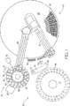
図1は、可動処理カルーセルと、インキュベーションカルーセルと、そしてサンプルのアッセイ前処理のための複数の処理ステーションを備えたアッセイ前プロセッサーを有する自動化学分析機の概略平面図である。
図2は、図1のアッセイ前プロセッサーの概略平面図である。
図3は、アッセイ前プロセッサーのタイミング図である。
好ましい具体例の詳細な説明
本発明の装置および方法は、図面の図1および2を特に参照して最初に記載されている。図1は、複数のサンプルカット14を支持するサンプルカップカルーセル12と、複数のクベット18を保持するのに適し、そして複数の試薬液カートリッジ20を提供するクベットカルーセル16を含んでいる慣用の自動化学分析機10のエレメントを概略的に示し、試薬液カートリッジは種々の熱的に制御された区域をカバーする蓋22の切り欠き部分の下に配置されるように図示されている。好ましくは試薬カートリッジは、E.I.du Pont de Nemours and Co.,Inc.Wilmington,DEからFLEXの商標名で販売されているような多数コンパートメント容器である。クベット18は、同じくE.I.du Pont de Nemours and Co.,Inc.により販売されているDimension化学分析機で行なわれるように、図示しないクベットフィルムカートリッジから透明フィルムの二つの異なる組成リボンをクベットカルーセル16の周縁へ引出すことによって形成することができる。好ましくはホイールの形のクベットカルーセル16は、クベット18を保持するための約100の別々の空胴を有し、各空胴の内壁は光の透過を許容する開口を持っている。試薬液およびサンプル液の添加を許容するため小さい開口が各クベット18の頂部に残っている。サンプル液アーム24と洗浄資源26は、サンプルカップカルーセル12とクベットカルーセル16の近くに配置される。サンプル液アーム24は慣用のサンプル液プローブ28を支持し、そしてサンプル液アーム24がサンプルカップカルーセル12と、クベット18と、そして洗浄資源26と交差する円弧を描くように回転シャフト27へ取付けられる。洗浄資源はプローブ28を洗浄化するために使用することができる。
第1の液体プローブ25はクベットカルーセル16の上に回転自在に取付けられ、そして適切な試薬液カートリッジ20から試薬を吸引し、そして各試薬液を化学分析機10により処理のためあらかじめ定めたクベット18内に沈着させるプローブ25はさらに、Dimension化学分析機に使用されるのと類似の試薬の吸引、分配および混合のために使用される超音波機構を含んでいる。水和、吸引、分配および混合機構はこの分野では良く知られているので、それらはこれ以上記載する必要はない。クベットカルーセル16の下に配置された図示しない測光分析手段は、各種波長においてクベット18を通る吸光度を測定し、それからサンプル液中の検体の存在を良く知られた分析技術を使用して決定することができる。このように、この化学分析機は慣用であり、そして例えば前出のE.I.du Pont de Nemours Co.,Inc.により販売されているDimension臨床分析機でよい。
本発明は、この分析機へアッセイ前サンプル処理モジュール30を追加する。このことは、化学分析機が高いサンプルスループットを維持する能力を減ずることなく、不均質アッセイを実施するため必要ないくつかの追加ステップを容易化する。処理モジュール30は、検体を含むサンプル液および/または試薬液のどちらか一方または両方を、それらが測定のためクベット18へ提供される前に処理することを許容する。サンプル処理モジュール30は、二つのアッセイ前サンプル処理カルーセル32および34を含んでいる。これらは熱チャンバー(図示せず)に収容された内側処理カルーセル32および外側インキュベーションカルーセル34であり、二つのカルーセルは共通の軸に同心に取付けられ、そして好ましくは共通の平面内に横たわる、両方とも好ましくは円形カルーセルの形である。両方のカルーセルは独立して可動であり、そして複数の個々のアッセイ前反応容器36を支持するための図示しないクリップでよいあらかじめ定めた数の容器保持手段を持っている。
インキュベーションカルーセル34および処理カルーセル32を共通軸のまわりを独立して回転するための駆動手段31が設けられ、駆動手段は典型的にはカルーセル32および34の各自上に配置された歯車と、モータ(図示せず)のシャフト上に取付けたピニオン歯車を含む。駆動手段は慣用の設計で良い。上に記載した移行ステーションは複数の処理ステーションの一つである。
インキュベーションカルーセル34は好ましくは45の別々の位置を含み、そして反応容器を、1)試薬添加、2)サンプル添加/吸引、および3)クベットおよび処理ステーションへまたはそれから移すため、および装填/除去のため提供することを許容するように配置される。このカルーセルは直径約10インチ(25.4cm)とすることができる。インキュベーションカルーセル34は駆動手段31により駆動され、そして単一のホームセンサーを使用する。その位置は、ステップモーターへ取付けたエンコーダーによりいつでも検証することができる。
インキュベーションカルーセル34は容器を水平にカルーセルからオン/オフに移すことを許容するようにスロットが設けられる。
容器36がインキュベーションカルーセル34上にある時、それらは、容器をそれらがカルーセルのまわりを移動する時案内し、そしてそれらを定常温度に保つ熱インキュベーショントラフの内側へ動く。インキュベーショントラフはアルミニウムであり、そして抵抗エレメントにより加熱される。サーミスターが容器に最も近い金属温度を感知する。
インキュベーションカルーセル作動は非同期的である。すなわちそれは45容器のどれでも三位置のどれかへ上に記載したようにいつでも位置決めすることができる。これはアッセイ仕様に融通性と完全なランダムアクセスを提供する。
処理カルーセル32は15の別々の位置を含み、そしてインキュベーションカルーセルの内側に同心状に配置される。処理カルーセルは、容器を、1)磁気分離、2)吸引/洗浄、3)再懸濁混合、および処理カルーセルをオン/オフにインキュベーションカルーセルへ移すために提供することを許容する。処理カルーセルは直径約7インチ(17.78cm)でよい。
処理カルーセル32は、インキュベーションカルーセルと同じ駆動手段31によって駆動される。インキュベーションカルーセルと同様に、処理カルーセルは容器のオン/オフ移しを許容するようにスロットが設けられる。容器はばねクリップによりカルーセル上の所定位置に保持される。
インキュベーションカルーセルと違って、処理カルーセルのシーケンシングは同期的もしくは反復的である。反応容器36がカルーセル上に存在する時はいつでも、カルーセルは機械的反復態様で割出し、各容器を分離−洗浄−混合ステップのシリーズを通って前進させる。
一般に反復作動はスループットを増強するが、しかしアッセイ仕様およびランダムアクセス能力へいくつかの制限を課す。しかしながら、処理カルーセルはインキュベーションカルーセルと独立に作動するので、融通性アッセイ仕様および完全なランダムアクセス処理が依然達成される。
ある種の不均質アッセイの感度要求は、処理ステーション効率が非常に高いことを要請する。本発明は、所望のゼロに近いバックグラウンドレベルを確実にするために各反応容器の反復洗浄を許容する。各目的には、各アッセイは合計4回の分離/洗浄シーケンスを持っている。
両方のカルーセル32および34をアクセスする共通の移行ステーション38は、反応容器36を二つのカルーセル32および34の間を移すためと、そして反応容器36をサンプル処理モジュール30から除去し、そしてそれらを図示しない廃物処理へ送るために設けられる。
慣用の設計でよい移行ステーション38(図2)は、反応容器36を処理カルーセルへまたはそれから移し、そしてインキュベーションカルーセル34から容器を装荷/除去するために使用される。すべての容器移動は、単に容器をスライダー39上のそれらの通路に沿ってスライドするだけで、水平面のみで行われる。スライダー39はステッパーモーター(図示せず)により駆動され、そして容器を移行ステーション38に沿ったどこでも、すなわちカルーセル32または34のどちらかの上に配置することができる。このスライダーの位置決めを検証するためにエンコーダーを使用し得る。設計は新しい容器が入って来て、そして古い容器を除去するのを許容しなければならないので、T字形通路46が採用される。ソレノイド駆動ゲート(図示せず)は新しい容器の装填を許容するために閉じられる。
新しい容器は供給通路44を通って容器移行ステーション38へ導かれる。移行ステーション近くの供給通路44の終わりに配置された駆動輪48は、システムが新しい容器をインキュベーションカルーセル34上へ移行のための位置へ装填している時、容器のスタック(図示せず)の積極的駆動を提供するために使用される。
使用済容器は、移行ステーションの出口通路(図示せず)中の穴の下に取付けたプラスチックシュートを通って廃物容器へ導かれる。
第2の液体プローブ40はクベットカルーセルの上に回転自在に取付けられ、そして適切な試薬液カートリッジ20から試薬液を吸引し、そのような試薬液をインキュベーションカルーセル34中のあらかじめ定めた反応容器36中に沈着するのに適している。サンプル液プローブ28も、(1)サンプル液がスケジュール化されたアッセイ前作業を受けた後反応容器36からサンプル液を吸引し、(2)サンプル液をさらに処理および測定のためあらかじめ定めたクベット中に沈着するのに適している。
本発明によれば、サンプル処理装置もしくはステーション42(図1)は、それらが反応容器36をアクセスできるように、処理カルーセル32のまわりの選択された周方向位置に配置される。処理カルーセル32は、処理カルーセル32の放射方向外側のインキュベーションカルーセル34(図1には明瞭化のため内側のように図示)と同心状に取付けられる。
これらのステーションは、反応容器36に収容されたサンプル液と試薬液の混合、反応容器に収容されたサンプル液と試薬液の洗浄、およびアッセイ前反応容器に収容された標識した磁性粒子を遊離標識または試薬液から分離を提供するのに適している。
二つの洗浄ステーションW1およびW2(図2)は、反応容器から未結合サンプルおよび/または試薬を吸引除去し、そして多分容器へ以後のステップのための洗浄緩衝液を補給するために使用される。
洗浄ステーションモジュールは、二つの容器を同時に洗浄することを許容する二つの二重洗浄モジュール(W1およびW2)を支持する鋳造品を含む。プローブは完全な吸引のため各容器の底との信頼できる接触を確実にするようにばね負荷される。プローブは隣接する容器上で作動する。もし一つの容器しか存在しなければ、一つだけのプローブが吸引/分配される。プローブはステッパモータにより上記配置される。この位置は各作動後ホームセンサーを用いて検証される。
二つの混合ステーションM1およびM2(図2)がある。それらは各洗浄の後洗浄緩衝液中に分離した磁性粒子を再懸濁するために使用される。ミキサーは渦外部ミキサー設計を採用し、これは混合中サンプル/試薬による汚染を回避する。混合ステーションMは、好ましくは化学研究室においてサンプルの取扱いにおいて通常のプラクティスであるように、反応容器36は渦混合作用を与える。この目的のための装置は入手可能であり、そして好ましくは反応容器の底に対して置かれ、偏心的に回転される外から取付けた円板を含んでいる。
混合ステーションの設計は、例えば本発明の譲受人へ譲渡されたBenin et al.の米国特許No.4,848,917に記載されているように、慣用である。好ましい具体例においては、外部接触は容器底先端と係合する混合パッドを用いて容器との間に形成される。容器はその時偏心運動に揺動され、搖動され、渦混合を発生する。混合パッドは通常容器底から0.050インチ(0.127cm)下方へくぼみ、そのため容器先端は洗浄カルーセルがそれらをステーション間を進めている間空であろう。容器が混合のための位置にある時、混合パッドは上昇して容器と接触する。この上昇は混合モーターが始動されそして一定の速度に達した時係合する外へ回動するカムによって達成される。混合パッドが適切に係合されたことを検出するためにセンサーが使用される。
洗浄ステーションについてと同様に、混合ステーションM1およびM2は二つの容器上で同時に作動することができる。通常二つの隣接する容器が同時に混合されるが、しかしミキサーはもし他の容器がなければ二つの隣接容器のどちらかを混合することができる。
分離ステーションS1ないしS9(図2)は、慣用で典型的であるように、未結合物質を吸引できるように、磁性固体支持粒子(米国特許No.5,104,808に記載されているような)を反応容器の壁へ引きつけるための反応容器の場所に隣接して配置された磁石を含んでいる。
図2は、記載したように、処理カルーセル32へ隣接して配置された種々の静止処理ステーション(前記した)を示している。カルーセル32および34の運動を制御するための駆動手段31は、分析機10に収容された制御ユニット、好ましくはマイクロプロセッサーに使用中央処理ユニット(CPU)によって慣用的に制御され、容器を後で記載するアッセイ前処理が行われる各処理ステーション42へインディクス段階的に動かす。制御は、典型的にはDimension臨床化学分析機に使用されているものと類似であり、そしてコンピューター使用電子機械的制御プログラミングの分野の当業者によって広く使用されているソフトウエアによって提供される。回転手段は好ましくは市販のステッパモータ機構である。
本発明によれば、処理カルーセル32は、種々のアッセイ前作業を実施することができる連続した処理位置もしくはステーションへ割出しされる。図2は、好ましくは以下のように分布したアッセイ前処理ステーションに関連する処理カルーセル32を示している。分離ステーション10個(S1・・・・・S9、S/D)、洗浄ステーション2個(W1,W2)、および混合ステーション2個(M1,M2)、および移行ステーション38。
次に本発明の処理カルーセル32の重要な時間割特徴が詳細に記載される。これらは図3に関して記載される作業ソフトウエアプログラムによる実行である。もし処理カルーセル32上の処理ステーションの数と位置の間に特定の関係が確立され、そして反応容器36が処理ステーション42へ反復して割出されるシーケンスが維持されるならば、不均質アッセイに供せられるサンプルのアッセイ前処理の効率を有意義に増加できることが発見された。これらのサンプルは、1回目試薬添加、サンプル−支持体分離、サンプル混合およびサンプル洗浄および/または2回目試薬添加、2回目サンプル−支持体分離、2回目サンプル混合および2回目サンプル洗浄を必要とし得る。
これら交番アッセイ前要求に関連するアッセイ前プロトコールを達成するため、いくつかの処理ステーション42,すなわちS,WおよびMへの反応容器36の各自のための運動の反復シーケンスもしくはパターンを使用できることが発見された。
本発明によれば、処理カルーセル32を一時に一位置へインデックスもしくはシーケンスする代わりに、容器を一時にインデックス位置のユニークなセグメントもしくはグループへ進めるために新規な技術が使用される。処理カルーセル32は15のステーションを持っており、それ故完全な1回転についてカルーセルをインデックスすべき15のインデックスもしくは位置が存在する。前進は常に同一方向であり、そして処理ホイール(図2および3)の+6インデックスもしくは位置の増分グループと、+7インデックスもしくは位置の間で交番する。このシーケンスを処理カルーセル32へ適用すると、移行ステーションである“X”において入り、そして合計30グループのインデックスへ前進するある反応容器は、以下のパターンですべてステーションを通って過渡する。

上の表1に記載したように、移行ステーションにおける入口点から出発し、処理カルーセル32中のすべての反応容器36のめいめいは、停止することなく5個の中間処理ステーションを通って6番目の次の処理ステーションS1まで反時計方向にインデックスされる。このように、ステーションXにある第1の反応容器は5個の中間処理ステーションを通って7番目の処理ステーションS1へ、内側カルーセル32の同期運動により反時計方向に移される。作動の同じコンスタントなあらかじめ定めた時間の後、処理カルーセル32は6つの中間処理ステーションを停止することなく通って7番目の次の処理ステーションS2へくり返してインデックスされる。1番から6番目の次の処理ステーションへ前方へインデックスされ、次にコンスタントなあらかじめ定めた作業時間サンプル処理が続き、そして次に7番目の次の処理ステーションへ前方へインデックスするこの運動の反復パターンは、上から見られるように、アッセイが実施されるにもかかわらず停止することなく常に同じ方向に、前方もしくは反時計方向にインデックスするのをくり返す。処理カルーセル32の反応容器36はそのため、6つのカルーセルステップインデックス“前進”運動を含み、各インデックスセグメント運動にアッセイ前サンプル処理のコンスタント時間量に対して指示された整列した処理ステーションMn,Sn,またはWnにおける停止時間が続く第1の回転運動を経験する。この6−7インデックスセグメントの反復パターンは、後で説明するように、5つの別々の処理、すなわち単一試薬不均質アッセイの場合のような、1回洗浄1回混合アッセイ前処理を実施するために必要な時にくり返り返される。いわゆる二試薬不均質アッセイの場合には、反応容器36は、後で説明するように追加の試薬処理のため処理カルーセル32から除去し、その後処理カルーセル32上へ再配置することができる。
このシーケンスを図2に示した処理カルーセル32配置へ適用すると、移行ステーション38から処理カルーセル32へ入り、そして合計30インデックスセグメントをインデックスされる容器は、カルーセルのまわりを完全に2回転し、そしてサンプル吸入が行われるインキュベーションカルーセル32へ移すため移行ステーション38は提供される前にすべての必要なステーションを通って過渡することが見られる。このシーケンスは、30のインデックスセグメントを使用して分離、洗浄および混合サイクルの別々の4洗浄サイクルを提供する。逐次アッセイの場合には、1回目洗浄サイクルが終了した後、反応容器は移行ステーションへ配置される。ある種の逐次アッセイは、インキュベーションカルーセル34への最初の移行後追加の試薬添加およびインキュベーション期間を必要とし、そしてその後処理カルーセル32へ分離プロセスを終了するため移し戻され、再び必要な第2,第3および第4洗浄サイクルを通って処理される。
この増加したスループットは、処理カルーセル32の反復運動を使用して可能となり、その場合は処理カルーセル上の反応容器36の各自は処理ステーションSn,MnおよびWnへ順序化された態様で提供され、各容器36は処理カルーセル32の同期運動の間それが動かされるステーションにより処理され、各容器はさらに同じコンスタントな時間量異なる装置Sn,MnおよびWnによって処理される。
これら洗浄サイクルのタイミングシーケンスは図3に示されており、そしてこのタイミングシーケンスは分析機10のCPUによって計算される。いくつかの処理ステーション42における明示時間に触れることなく、いくつかの洗浄サイクルを形成する反復シーケンスは表2を参照して最良に理解し得る。各処理ステーションへそのステーションの能力に関係なく同じコンスタントな時間量の割当てと組合わせた、処理ステーションおよび装置の数の適切な選択は、処理カルーセル32の通常の期待を上廻るスループットを可能にする。
さらに、本発明によれば、最大14までの複数の反応容器を取り扱うことができ、そして反応容器の各自を必要な資源へ必要な順序で提供する。資源ステーションの数は14ステーションに等しい。
この技術は、以下の利益を提供する。
−W1洗浄ステーションを最初の2洗浄に、そしてW2洗浄ステーションを最終2洗浄に使用するので、減少したキヤリーオーバー可能性。
−洗浄ステーションおよびミキサーが相互に隣接して配置され、二つの洗浄プローブおよびミキサーコンパクト設計のため集団とすることを許容する。
−第1相サンプル洗浄および第2相試薬洗浄を要する逐次アッセイフォーマットを処理する時の増加したスループット。
支持装置(モーター、ポンプ、共通の攪拌パッド、ドレーン等)の最大利用を達成するために似た処理ステーションを相互に隣接配置する望ましい結果に加え、一旦、例えば高ボリューム処理の間発生するように、処理カルーセル32が反応容器36で完全に一杯になれば、すべての容器は、XもしくはD位置に配置された容器を除き、すべての容器は分離または混合ステーションのどちらかにおいて活発に使用されている。13もの他の反応容器36は処理カルーセル32によって提供されるアッセイ前処理位置における異なる段階にあり、移行ステーションXが空いていることを要するのみで追加の反応容器がカルーセルへ入ることを許容する。
本発明は、当初の洗浄サイクルと、次に抗体の標識を達成するための試薬添加と、そして最終洗浄サイクルを必要とする不均質逐次アッセイフォーマットを処理する時に増加したスループットを提供するために、反応容器36の新規な位置決めおよび前進を使用する。この装置の驚くべき結果は、第1回および第2回インキュベーションを必要とする競合アッセイフォーマットについて高いスループットを達成できる能力である。スループットは、要求に役立つ利用し得る資源と、そしてどのようにうまく資源がスケジュール化されるかどいうアッセイ要件の関数である。これらすべてがバランスされなければならない。本発明は、アッセイが同時か逐次かに関係なく、最適スループットを提供するためのこれらすべての必須要素の適切なバランスを提供することがわかった。
最大15の反応容器36が装填された時、すべての容器は、処理カルーセル32の逐次的ステッピング運動を中断することなく殆ど連続態様で分離、洗浄および混合の必要な段階を通って逐次ステップ前進し得る。この特徴は、アッセイ前ステップが、各反応容器の36nアッセイ前処理を他の容器の処理開始前に終了する、および/または少数の反応容器をアッセイ前処理のため組にする慣用のパターンで処理される場合を上廻る処理時間の有意義な短縮を提供することがわかった。
特定の具体例において、本発明のアッセイ前処理カルーセル32は、処理カルーセル32の各ステップのためのインデックス時間10.8秒を使用して不均質アッセイを処理するように設計され、そして図3に示されている。このため逐次不均質アッセイの各ステーションにおいて指示された時間のための各自S,WおよびMのステーション42を含む4洗浄サイクルについて要する時間は、30×10.8秒すなわち324秒である。同時アッセイは、第1洗浄サイクル、次にインキュベーションのため移し換え、次に第2,第3および第4洗浄サイクルのため移し戻しを使用する。
近代的不均質アッセイの感度要求のため、洗浄は非常に高い効率を与え、そして容器間のキャリーオーバーを最小にする態様で実施されることが非常に重要である。本発明はゼロに近いバックグラウンドを産む。これはステップ6および13のステーションW1により2回のかなりの粗い洗浄を実施することにより達成される。最終バックグラウンドレベルを低い値へ減らすため、ステーションW2における第3洗浄およびステーションW2における最後の第4洗浄がこれに続く。ここで使用するように、「磁性粒子」もしくは単に「磁場に応答する粒子」はこの分野で既知のどれでもよい。それらは好ましくは常磁性であり、そして磁場の不存在下小さい塊が生成するような小さい残留磁気を持っている。Lau et al.の米国特許No.4,661,408に記載されたタイプの好ましい磁性粒子が採用される。それにより分離ステーションSは混合プロセスを進めるために結合および遊離相を分離する。
ここに開示した具体例は本発明の原理の例証であり、本発明の範囲内である他の修飾を採用できることを理解すべきである。従って本発明は明細書に詳細に示し記載した具体例に制限されず、以下の請求の範囲によってのみ規定される。 Field of the invention
The present invention relates to a method and apparatus for processing a fluid sample, and in particular for processing biological fluids such as urine, serum, plasma, cerebrospinal fluid and the like. In particular, the present invention provides methods and means for automatically processing a sample through a sequence of processing steps performed during a heterogeneous immunoassay.
Background of the invention
Fully automated diagnostic analyzers are commercially utilized to perform chemical and immunoassays for biological fluids in urine, serum, plasma, and cerebrospinal fluid. In general, the reaction between the analyte in the patient sample and the reagents used during the assay results in the generation of certain signals that can be measured by the analyzer. From this signal, the analyte concentration in the patient sample can be calculated.
Heterogeneous immunoassays are widely used to allow both large and small size analysis where their flexibility is measured. These require three basic steps: (1) binding the analyte to the solid phase, (2) separating the unbound analyte from the bound solid phase, and (3) measuring the bound analyte. The physical separation step eliminates most of the interfering substances, thereby providing higher sensitivity. Heterogeneous assays include competitive immunoassays and sandwich assays. Diagnostic analyzers generally employ various processing stations in which processing operations such as sample, reagent addition, separation, washing and mixing are performed to provide such an assay.
In competitive assays, antibodies against the antigen contained in the first reagent are typically bound to derivatized magnetic particles, ie, particles that are responsive to a magnetic field, to form a solid phase. A second reagent consisting of the antigen bound to the label and the patient sample are mixed with the solid phase in a test tube. If no patient antigen is present, as much as 50% of the antigen-label will bind to the antibody on the magnetic solid phase. If a patient antigen is present, some of the antibody binds to the patient antigen and is not provided to the labeled antigen. As a result, the increased amount of patient antigen leads to the decreased amount of labeled antigen. Magnetic separation concentrates solid phase magnetic particles with bound label into pellets on the test tube wall. The free label can then be removed by thorough washing and aspiration. After separation and removal of free label, other reagents are added so that bound label can be measured.
In a typical sandwich immunoassay, multiple steps are used. That is, an antibody against an antigen is bound to magnetic particles at a high concentration compared to the amount of patient antigen in the sample. Patient antigens are captured by antibodies on the magnetic particles and the particles (with bound or captured patient antigens) are separated from interfering substances in the sample. A second reagent containing a second antibody conjugated with a label is added. This second antibody binds to the patient antigen captured by the first antibody on the magnetic particle, and the second antibody label is firmly immobilized by the antigen to the first antibody on the magnetic particle. Sandwich formation occurs. At this point, thorough washing and magnetic separation allows determination of bound label proportional to patient antigen, and excess label of the second reagent has been removed by washing action.
In both types of heterogeneous immunoassays, considerable resources and time are required to achieve a sufficiently high degree of washing to eliminate interfering components and prevent spurious assay results. The degree to which this is achieved in an automated analyzer is an important contributor to the sensitivity of the analyzer.
High throughput is a desirable characteristic of such an analyzer. An important contributor to maintaining high throughput is the ability to process multiple samples through the various different heterogeneous assay processing steps required before the signal measurement step is performed. These multiple processing steps tend to limit throughput. New automated analyzers, especially those that include multiple “sandwich” heterogeneous immunoassays that often require a large number of separate processing operations, can detect a wide variety of analytes while taking up minimal physical space Capability is an important performance benefit. In general, repeated uninterrupted operations increase throughput because multiple containers can be processed simultaneously.
Iterative work is difficult to achieve, especially in the case of heterogeneous “sandwich” immunoassays. This is a particularly difficult task even when performed manually. This is a particular problem when automated washing operations are incorporated into automated analyzers that are capable of many types of immunoassays. This requires multiple wash stations, and this is typically accomplished by installing such multiple wash stations in an automated analyzer. For example, the sensitivity requirements of certain heterogeneous assays require that the wash efficiency must be very high. This is usually obtained by repeated washing, with successive washings removing unwanted liquids and reagents so that progressively lower background levels are obtained. At the same time, such cleaning schemes impose restrictions on the use of various processing resources. This is because the analyzer needs to be stationary during the cleaning operation. Typically, the assay requires a total of 4 washes alternating with 4 separation steps. Thus, an important design feature of this type of analyzer is the ability to make the unwashed resources contained for one sample productive while one of the other samples is being washed. However, some mechanisms required to operate several cleaning stations individually and the mechanisms required for the cleaning station itself can be quite expensive.
US Pat. No. 4,459,269, assigned to Clincon, describes an automated analyzer with a circular plate that can be rotated in stages. It has a plurality of reaction tubes at its periphery and several reagent supply stations arranged at different locations around such periphery. The use of multiple stations implements several different test methods. It does not provide flexibility to the machine and again does not provide the necessary washing for heterogeneous immunoassays.
A conventional chemical analyzer manufactured by Hitachi Ltd., model number 7050, has a plurality of cleaning probes connected or grouped together. When this is achieved, the ability of the instrument to perform a large number of analytical operations is simultaneously impaired.
Laska et al., US Pat. No. 5,104,808, assigned to the assignee of the present invention, also describes an analyzer that collects wash probes. The wash probes are grouped, but separated into two groups to achieve the goal of providing a washed solid phase containing a minimal amount of the original serum / conjugate matrix. According to the Laska et al. Patent, the washing means includes at least two washing probes linked or grouped for simultaneous insertion into the reaction vessel at different processing locations. In addition, the wash probe is placed in succession on the first of the sample and / or reagent locations in the sequence. The means for adding the sample and / or reagent is disabled at each cycle for a number of containers that precede and track the first and last container receiving the sample or reagent. This number corresponds to the number of processing positions between wash probes that can be inserted.
Wakatake, U.S. Pat. No. 5,183,638, discloses an analyzer in which the reaction vessel is transported through several devices for the addition and agitation of the necessary magnetic particles during the EIA immunoassay.
Sakagami U.S. Pat. No. 5,192,505 is provided with two different reaction lines driven by only one drive, one line suitable for providing assay work involved in colorimetric measurements, The other line discloses an analyzer that is suitable for providing the assay work involved in immunoagglutination measurements. The advantage of this analyzer is its small physical size maintenance.
One other feature used in automated analyzers is the assignment method used to provide samples to various assay tools. As described in US Pat. No. 5,212,094, an automated chemical analyzer uses an odd number of reaction vessels arranged in a circular pattern. These reaction vessels are rotated one after the other in a circular pattern half turn plus the distance between the reaction tubes. Such patterns can be used to position wash stations together in close proximity, thereby facilitating analyzer compactness, but such analyzers perform heterogeneous immunoassays. It is not possible.
The analyzer of US Pat. No. 5,352,612 includes a movable sample support for holding samples located at a first plurality of positions for movement in a first direction. The indexing drive for the sample support moves the samples in the sample support in a first direction with a set of increments that represent the amount of sample movement, each increment corresponding to the number of samples. Such a system allows separation of the logical space in the system from the physical space, allowing for proper sequencing of work in space and time, while allowing more freedom in installing mechanical equipment To do. This system requires a very complex time indexing motion of the rotating sample support that is determined differently for every loading of the sample support. As best understood, this movement pattern is determined by the number of pairs of reaction cuvettes. This pattern varies depending on the assay performed, and the time spent before different processing resources varies according to the processing resource's work.
US Pat. No. 5,380,487, assigned to Pasteur Sanofi Diagnostics, describes an analyzer in which a fixed work sequence that begins and ends within a fixed time cycle is assigned to assay resources. When different samples with different assay protocols are entered into the analyzer, the assay resource requirements for the different samples are determined and the required resource time slots are assigned to it. There is also the convenience of dealing with heterogeneous immunoassays, but the incubator belt physically intersects the wash wheel, so the incubator belt index time, wash wheel index time, and the reaction vessel follow the wash wheel. A complex relationship is established between the cycle times of the work performed on the reaction vessel when moving. In addition, the control means will determine which time-based assay resources to handle the cycle of assay resource tests and then their availability check against resource allocations for other ongoing test processes. You have to decide what it takes. If there is no discrepancy in the allocation of assay resources, the processing of the reaction vessel will follow the previous reaction vessel sequentially. Therefore, the start of sample processing for a test can be delayed until all necessary assay resources are available for processing. While such timetables can reduce the total number of indexing cycles required to complete all test processing, timetable inconsistencies delay processing start and result in processing resource play.
There is a need for improved automated analyzers and associated methods for handling samples from prior art studies taken against problems encountered in automated processing of complex heterogeneous immunoassays. At the same time, there is a need for maintaining high throughput without introducing complex programming and at the same time minimizing the physical dimensions of the analyzer. In particular, there is a need for a method that provides bound / unbound analyte separation and washing with minimal processing time in a pattern that enhances / maintains the throughput of automated analyzers.
Accordingly, it is an object of the present invention to provide an apparatus that provides the work required for heterogeneous immunoassays with increased efficiency and greatly simplified sample handling techniques.
Summary of the present invention
Many of these disadvantages of the prior art are overcome by the use of the apparatus and / or method of the present invention. The present invention provides a method of using a treated carousel and an incubation carousel to detect an analyte in a sample and pretreating a sample having a solid support for a heterogeneous assay. This method
(A) adding a labeling reagent comprising the support to a sample on an incubation carousel, thereby forming a labeled sample analyte-support complex;
(B) transferring the sample and reagent to the processing carousel;
(C) separating the solid support from at least a portion of the sample and reagents;
(D) washing the solid support;
(E) mixing the solid support with a wash buffer;
(F) transferring the solid support and buffer to the incubation carousel; and
(G) including a step of detecting the specimen.
The number and sequence of these steps is transferred to the processing carousel so that each reaction vessel can move from the processing carousel at the transfer station for additional processing using a single transfer station without interrupting the repeated synchronization pattern. Selected to be removed and returned to the processing carousel.
Such a new approach makes it possible to achieve the stringent requirements for sample washing required in heterogeneous immunoassays. This is true even if some tests or assays have different reaction times before washing and include reagent addition and alternating incubation steps within the required washing cycle.
Associated with this method is an automated sample processor for performing pre-immunoassay work on a sample using a solid support. This processor in the analyzer for detecting an analyte in a sample using a solid support is
A treated carousel supporting multiple reaction vessels suitable for holding each sample;
An incubation carousel that is arranged concentrically with the treated carousel and supports a plurality of reaction vessels suitable for holding each sample;
A stationary processing station located adjacent to one of the carousels, the means for separating the solid support from the contents of the reaction vessel, the means for washing the contents of the reaction vessel, and the reaction A stationary processing station having means for mixing the contents of the container;
Drive means for rotating each carousel independently of each other, wherein the process carousel is driven in a repetitive manner to place its reaction vessel in the position of an adjacent predetermined processing station;
Transition means to improve processing time by transferring reaction vessels between said carousels, thereby allowing incubation of all reaction vessels on the incubation carousel without interrupting sample processing on the processing carousel
It has.
The processing stations are arranged in a preselected order that allows the processing carousel to place its reaction vessels in a repeating sequence of separation and washing steps. More specifically, the reaction vessel repeat sequence is separation, washing and mixing. These features have high throughput, reduce the cost of processing stations by placing similar functions in one place, and allow the sample being processed to be removed at any time for incubation or measurement Provide an analyzer.
[Brief description of the drawings]
The invention will be more fully understood from the following detailed description with reference to the accompanying drawings, which form a part of this application.
FIG. 1 is a schematic plan view of an automated chemical analyzer having a mobile processing carousel, an incubation carousel, and a pre-assay processor with multiple processing stations for pre-assay processing of samples.
FIG. 2 is a schematic plan view of the pre-assay processor of FIG.
FIG. 3 is a timing diagram of the pre-assay processor.
Detailed description of preferred embodiments
The apparatus and method of the present invention are first described with particular reference to FIGS. 1 and 2 of the drawings. FIG. 1 shows a conventional automatic including a
A first
The present invention adds a pre-assay
Drive means 31 are provided for independently rotating the
The
When the
Incubation carousel operation is asynchronous. That is, it can be positioned at any time as described above in any of the three positions in any of the 45 containers. This provides flexibility and complete random access to assay specifications.
The
The
Unlike the incubation carousel, the sequencing of the treated carousel is synchronous or iterative. Whenever
In general, repetitive operation increases throughput, but imposes some limitations on assay specifications and random access capabilities. However, because the processing carousel operates independently of the incubation carousel, versatile assay specifications and complete random access processing are still achieved.
The sensitivity requirements of certain heterogeneous assays require very high processing station efficiency. The present invention allows repeated washing of each reaction vessel to ensure a background level close to the desired zero. For each purpose, each assay has a total of 4 separation / wash sequences.
A
A transfer station 38 (FIG. 2), which may be a conventional design, is used to transfer the
New containers are directed through the
The used container is led to a waste container through a plastic chute mounted under a hole in the exit passage (not shown) of the transition station.
A second
In accordance with the present invention, sample processing devices or stations 42 (FIG. 1) are located at selected circumferential positions around the
These stations mix the sample solution and reagent solution contained in the
Two wash stations W1 and W2 (FIG. 2) are used to aspirate unbound sample and / or reagents from the reaction vessel and possibly replenish the vessel with wash buffer for subsequent steps.
The cleaning station module includes a casting that supports two double cleaning modules (W1 and W2) that allow two containers to be cleaned simultaneously. The probe is spring loaded to ensure reliable contact with the bottom of each container for complete suction. The probe operates on an adjacent container. If there is only one container, only one probe is aspirated / dispensed. The probe is arranged by a stepper motor. This position is verified using the home sensor after each actuation.
There are two mixing stations M1 and M2 (FIG. 2). They are used to resuspend the separated magnetic particles in the wash buffer after each wash. The mixer employs a vortex external mixer design, which avoids contamination by sample / reagent during mixing. The
The design of the mixing station is described, for example, in Benin et al., Assigned to the assignee of the present invention. U.S. Pat. No. 4,848,917, which is conventional. In a preferred embodiment, the external contact is made between the container using a mixing pad that engages the container bottom tip. The container is then oscillated and perturbed by eccentric motion, generating vortex mixing. The mixing pad is usually recessed 0.050 inches (0.127 cm) below the bottom of the container so that the container tip will be empty while the cleaning carousel advances them between stations. When the container is in the position for mixing, the mixing pad rises and contacts the container. This rise is accomplished by an outwardly rotating cam that engages when the mixing motor is started and reaches a certain speed. A sensor is used to detect that the mixing pad is properly engaged.
As with the washing station, the mixing stations M1 and M2 can be operated simultaneously on two containers. Usually two adjacent containers are mixed at the same time, but the mixer can mix either of two adjacent containers if there is no other container.
Separation stations S1 to S9 (FIG. 2) are magnetic solid support particles (as described in US Pat. No. 5,104,808) so that unbound material can be aspirated, as is conventional and typical. ) Is located adjacent to the location of the reaction vessel for attracting it to the wall of the reaction vessel.
FIG. 2 shows various stationary processing stations (described above) positioned adjacent to the
In accordance with the present invention, the
The important timetable features of the
It has been discovered that a repetitive sequence or pattern of movement for each of the
In accordance with the present invention, instead of indexing or sequencing the
As described in Table 1 above, starting from the entry point at the transition station, all of the
When this sequence is applied to the
This increased throughput is possible using the repetitive motion of the
The timing sequence of these wash cycles is shown in FIG. 3, and this timing sequence is calculated by the
Furthermore, according to the present invention, up to 14 reaction vessels can be handled, and each of the reaction vessels is provided to the necessary resources in the required order. The number of resource stations is equal to 14 stations.
This technology provides the following benefits.
-Reduced carryover potential since the W1 wash station is used for the first 2 washes and the W2 wash station is used for the final 2 washes.
-The wash station and the mixer are placed next to each other, allowing the two wash probes and the mixer compact design to be clustered.
-Increased throughput when processing sequential assay formats that require first phase sample washes and second phase reagent washes.
In addition to the desired result of placing similar processing stations adjacent to each other to achieve maximum utilization of support devices (motors, pumps, common agitation pads, drains, etc.) once generated, eg during high volume processing Once the
The present invention provides increased throughput when processing heterogeneous sequential assay formats that require an initial wash cycle, followed by reagent addition to achieve antibody labeling, and a final wash cycle. A new positioning and advancement of the
When up to 15
In a specific embodiment, the
Due to the sensitivity requirements of modern heterogeneous assays, it is very important that washing be performed in a manner that provides very high efficiency and minimizes carryover between containers. The present invention produces a background close to zero. This is accomplished by performing two fairly rough washes with station W1 in
It should be understood that the specific examples disclosed herein are illustrative of the principles of the present invention and that other modifications within the scope of the present invention may be employed. Accordingly, the invention is not limited to the specific examples shown and described in detail in the specification, but is defined only by the following claims.
Claims (8)
(a)該インキュベーションカルーセル上の反応容器の中のサンプルへ固体支持体を含む試薬を添加するステップ;
(b)該反応容器を該インキュベーションカルーセルから該処理カルーセル上の反応容器支持位置へ、両カルーセルをアクセスする移行ステーションを用いて移すステップ;
(c)該固体支持体を該サンプル及び試薬から、前記処理カルーセルの最も近くに配列された処理ステーションを用いて分離するステップ;そして、
(d)該固体支持体を前記処理カルーセルの最も近くに配列された処理ステーションを用いて洗浄するステップを含み、その中でステップ(c)及び(d)は;
(e)該処理カルーセルを第1のインデックス位置の数だけ前進させ、そしてコンスタント時間量の間、処理ステーションで停止させるステップ;
(f)前記処理カルーセルを第2のインデックス位置の数だけ前進させ、そして前記コンスタント時間量の間、処理ステーションで停止させるステップ;
(g)イムノアッセイに試薬の添加が必要でない場合は、ステップ(e)及び(f)を前処理を完了するために必要なだけ繰り返すステップ;そして、
(h)アッセイ試薬の添加が必要である場合、前記移行ステーション上で反応容器が最初に停止した時に該反応容器を該処理カルーセルから該インキュベーションカルーセルへ移し、そしてそこで必要な試薬を添加するステップ;そして、
(i)試薬の添加が必要なアッセイがステップ(e)及び(f)の前進モーションを変えることなく該処理カルーセル上で処理されることができるように、該前処理操作が完了させられる前に前記処理カルーセル上の該反応容器を取り換えるステップ;そして、
(j)試薬の添加が必要でない該イムノアッセイのサンプル処理時間が短縮されないように、ステップ(e)及び(f)を必要なだけ繰り返すステップ:
を含むイムノアッセイを実行する方法。There are concentrically mounted processing carousels with incubation carousels having a predetermined number of reaction vessel support locations and methods for performing immunoassays on the incubation carousels:
(A) adding a reagent comprising a solid support to a sample in a reaction vessel on the incubation carousel;
(B) transferring the reaction vessel from the incubation carousel to a reaction vessel support location on the processing carousel using a transfer station that accesses both carousels;
(C) separating the solid support from the sample and reagents using a processing station arranged closest to the processing carousel; and
(D) washing the solid support using a treatment station arranged closest to the treatment carousel, wherein steps (c) and (d) include:
(E) advancing the process carousel by the number of first index positions and stopping at the process station for a constant amount of time;
(F) advancing the processing carousel by a number of second index positions and stopping at the processing station for the constant amount of time;
(G) if no reagent addition is required for the immunoassay, repeating steps (e) and (f) as many times as necessary to complete the pretreatment; and
(H) if addition of assay reagents is required, transferring the reaction vessel from the processing carousel to the incubation carousel when the reaction vessel is first stopped on the transfer station and adding the necessary reagents there; And
(I) before the pretreatment operation is completed so that an assay that requires the addition of reagents can be processed on the processing carousel without changing the forward motion of steps (e) and (f). Replacing the reaction vessel on the processing carousel; and
(J) Repeat steps (e) and (f) as necessary so that the sample processing time of the immunoassay that does not require the addition of reagents is not reduced:
A method of performing an immunoassay comprising:
Applications Claiming Priority (3)
| Application Number | Priority Date | Filing Date | Title |
|---|---|---|---|
| US63861896A | 1996-04-26 | 1996-04-26 | |
| US08/638,618 | 1996-04-26 | ||
| PCT/US1997/006936 WO1997041445A1 (en) | 1996-04-26 | 1997-04-25 | Method and apparatus for pre-treating samples in an automatic chemical analyzer |
Publications (2)
| Publication Number | Publication Date |
|---|---|
| JPH11509635A JPH11509635A (en) | 1999-08-24 |
| JP3673926B2 true JP3673926B2 (en) | 2005-07-20 |
Family
ID=24560761
Family Applications (1)
| Application Number | Title | Priority Date | Filing Date |
|---|---|---|---|
| JP53904997A Expired - Fee Related JP3673926B2 (en) | 1996-04-26 | 1997-04-25 | Method and apparatus for preprocessing samples in an automated chemical analyzer |
Country Status (6)
| Country | Link |
|---|---|
| US (1) | US5985672A (en) |
| EP (1) | EP0835452B1 (en) |
| JP (1) | JP3673926B2 (en) |
| DE (1) | DE69733927T2 (en) |
| ES (1) | ES2245462T3 (en) |
| WO (1) | WO1997041445A1 (en) |
Cited By (1)
| Publication number | Priority date | Publication date | Assignee | Title |
|---|---|---|---|---|
| JP2020510196A (en) * | 2017-03-16 | 2020-04-02 | シーメンス・ヘルスケア・ダイアグノスティックス・インコーポレーテッドSiemens Healthcare Diagnostics Inc. | System and method for temperature control of an incubation system in a diagnostic analyzer |
Families Citing this family (57)
| Publication number | Priority date | Publication date | Assignee | Title |
|---|---|---|---|---|
| US5856194A (en) * | 1996-09-19 | 1999-01-05 | Abbott Laboratories | Method for determination of item of interest in a sample |
| DE69942975D1 (en) * | 1998-02-27 | 2011-01-05 | Ventana Med Syst Inc | AUTOMATED MOLECULAR PATHOLOGY APPARENT WITH INDEPENDENT OBJECT CARRIER WARMERS |
| US6582962B1 (en) * | 1998-02-27 | 2003-06-24 | Ventana Medical Systems, Inc. | Automated molecular pathology apparatus having independent slide heaters |
| US8337753B2 (en) | 1998-05-01 | 2012-12-25 | Gen-Probe Incorporated | Temperature-controlled incubator having a receptacle mixing mechanism |
| ATE369915T1 (en) | 1998-05-01 | 2007-09-15 | Gen Probe Inc | INCUBATOR FOR AUTOMATIC ANALYZER |
| FI113703B (en) * | 1999-03-12 | 2004-05-31 | Innotrac Diagnostics Oy | Diagnostic measuring device |
| US6627156B1 (en) | 2000-06-22 | 2003-09-30 | Beckman Coulter, Inc. | Cap piercing station for closed container sampling system |
| US6442440B1 (en) | 2000-06-24 | 2002-08-27 | Dade Behring Inc. | Computer interface module having a flat menu |
| JP4128449B2 (en) * | 2001-01-23 | 2008-07-30 | 株式会社日立製作所 | Automatic analyzer |
| US7217391B2 (en) * | 2001-03-16 | 2007-05-15 | Beckman Coulter, Inc. | Rotary incubation station for immunoassay systems |
| US7250303B2 (en) | 2001-07-20 | 2007-07-31 | Ortho-Clinical Diagnostics, Inc. | Chemistry system for a clinical analyzer |
| US7015042B2 (en) * | 2001-07-27 | 2006-03-21 | Dade Behring Inc. | Increasing throughput in an automatic clinical analyzer by partitioning assays according to type |
| EP1890127B1 (en) | 2002-04-15 | 2013-07-03 | Ventana Medical Systems, Inc. | Automated high volume slide staining system |
| US7468161B2 (en) | 2002-04-15 | 2008-12-23 | Ventana Medical Systems, Inc. | Automated high volume slide processing system |
| US11249095B2 (en) | 2002-04-15 | 2022-02-15 | Ventana Medical Systems, Inc. | Automated high volume slide processing system |
| US7597847B2 (en) | 2003-03-31 | 2009-10-06 | Ortho-Clinical Diagnostics, Inc. | Analyzer having a stationary multifunction probe |
| US20040230400A1 (en) * | 2003-05-13 | 2004-11-18 | Tomasso David Angelo | Analyzer having concentric rotors |
| CA2949524C (en) * | 2003-07-18 | 2017-07-04 | Bio-Rad Laboratories, Inc. | System and method for multi-analyte detection |
| US7169356B2 (en) * | 2003-07-18 | 2007-01-30 | Dade Behring Inc. | Random access reagent delivery system for use in an automatic clinical analyzer |
| US7338803B2 (en) * | 2003-07-18 | 2008-03-04 | Dade Behring Inc. | Method for increasing capacity in an automatic clinical analyzer by using modular reagent delivery means |
| US7381370B2 (en) * | 2003-07-18 | 2008-06-03 | Dade Behring Inc. | Automated multi-detector analyzer |
| US8043562B2 (en) | 2003-12-08 | 2011-10-25 | Ortho-Clinical Diagnostics, Inc. | Analyzer having removable holders or a centrifuge |
| DE10360526A1 (en) * | 2003-12-22 | 2005-07-14 | Roche Diagnostics Gmbh | Reagent cassette with reagent container for particle-containing reagent for its noninvasive homogenization |
| JP3962385B2 (en) * | 2004-03-11 | 2007-08-22 | 株式会社日立製作所 | Immunoassay device and immunoassay method |
| US7842504B2 (en) * | 2004-04-02 | 2010-11-30 | Siemens Healthcare Diagnostics Inc. | Method for increasing throughput in an automatic clinical analyzer by duplicating reagent resources |
| US7776263B2 (en) * | 2004-10-29 | 2010-08-17 | Abbott Laboratories Inc. | Apparatus for providing homogeneous dispersions |
| EP1861721B1 (en) | 2005-03-10 | 2017-05-03 | Gen-Probe Incorporated | Systems and methods to perform assays for detecting or quantifying analytes within samples |
| US20080020469A1 (en) * | 2006-07-20 | 2008-01-24 | Lawrence Barnes | Method for scheduling samples in a combinational clinical analyzer |
| US7985375B2 (en) | 2007-04-06 | 2011-07-26 | Qiagen Gaithersburg, Inc. | Sample preparation system and method for processing clinical specimens |
| US8703492B2 (en) | 2007-04-06 | 2014-04-22 | Qiagen Gaithersburg, Inc. | Open platform hybrid manual-automated sample processing system |
| US8066943B2 (en) * | 2007-11-16 | 2011-11-29 | Siemens Healthcare Diagnostics Inc. | Clinical analyzer having a variable cycle time and throughput |
| JP5097522B2 (en) * | 2007-12-07 | 2012-12-12 | 株式会社日立ハイテクノロジーズ | Automatic analyzer |
| EP2128627B1 (en) | 2008-05-30 | 2013-01-09 | F. Hoffmann-La Roche AG | Analyzer for performing medical diagnostic analysis |
| US10184862B2 (en) | 2008-11-12 | 2019-01-22 | Ventana Medical Systems, Inc. | Methods and apparatuses for heating slides carrying specimens |
| US20120048036A1 (en) * | 2009-04-09 | 2012-03-01 | Hitachi High-Technologies Corporation | Automatic analysis apparatus |
| AU2010282784C1 (en) | 2009-08-13 | 2014-03-13 | Siemens Healthcare Diagnostics Inc. | Methods and apparatus for ascertaining interferents and physical dimensions in liquid samples and containers to be analyzed by a clinical analyzer |
| WO2011063139A1 (en) | 2009-11-18 | 2011-05-26 | Qiagen | Laboratory central control unit method and system |
| JP5478360B2 (en) * | 2010-05-20 | 2014-04-23 | 株式会社日立ハイテクノロジーズ | Automatic analyzer |
| US9046507B2 (en) | 2010-07-29 | 2015-06-02 | Gen-Probe Incorporated | Method, system and apparatus for incorporating capacitive proximity sensing in an automated fluid transfer procedure |
| US8718948B2 (en) | 2011-02-24 | 2014-05-06 | Gen-Probe Incorporated | Systems and methods for distinguishing optical signals of different modulation frequencies in an optical signal detector |
| WO2012130107A1 (en) * | 2011-03-25 | 2012-10-04 | 深圳迈瑞生物医疗电子股份有限公司 | Apparatus for automatic analysis and sample analysis method thereof |
| AU2013202808B2 (en) | 2012-07-31 | 2014-11-13 | Gen-Probe Incorporated | System and method for performing multiplex thermal melt analysis |
| ES2934684T3 (en) | 2013-03-15 | 2023-02-24 | Abbott Lab | Automated diagnostic analyzers having vertically arranged carousels and related methods |
| EP2972402B1 (en) | 2013-03-15 | 2023-12-20 | Abbott Laboratories | Diagnostic analyzers with pretreatment carousels and related methods |
| JP6169245B2 (en) | 2013-03-15 | 2017-07-26 | アボット・ラボラトリーズAbbott Laboratories | Automatic diagnostic analyzer with rear accessible truck system and related method |
| JP6249626B2 (en) * | 2013-04-10 | 2017-12-20 | 株式会社日立ハイテクノロジーズ | Automatic analyzer |
| CN104111341B (en) * | 2013-04-16 | 2017-10-17 | 深圳迈瑞生物医疗电子股份有限公司 | Automatic analysing apparatus and its analysis method and analysis system |
| CN105793690B (en) | 2013-12-13 | 2020-01-03 | 文塔纳医疗系统公司 | Automated histological processing of biological samples and related techniques |
| FI127032B (en) * | 2014-03-21 | 2017-10-13 | Magnasense Tech Oy | Measuring arrangement, apparatus for a measuring arrangement and method for measuring a sample |
| EP3131651B1 (en) * | 2014-04-18 | 2019-01-09 | Siemens Healthcare Diagnostics Inc. | Reaction vessel handling apparatus, testing apparatus, and methods using same |
| CN105628948B (en) * | 2016-03-04 | 2018-03-30 | 深圳普门科技有限公司 | A kind of high speed c reactive protein analyzer and its analysis method |
| CN109975277A (en) * | 2017-12-28 | 2019-07-05 | 深圳市新产业生物医学工程股份有限公司 | Chemiluminescence detector and its detection method |
| CN110133248B (en) * | 2018-02-08 | 2022-10-11 | 成都深迈瑞医疗电子技术研究院有限公司 | Incubation detection device, sample analyzer and control method thereof |
| JP6659773B2 (en) * | 2018-06-27 | 2020-03-04 | シスメックス株式会社 | Sample analyzer |
| CN109655627A (en) * | 2018-12-17 | 2019-04-19 | 宁波海壹生物科技有限公司 | A kind of cleaning device with incubation function |
| US20200233002A1 (en) * | 2019-01-17 | 2020-07-23 | Jose Maria Las Navas Garcia | Multiple sample automatic gravimetric dosing and cleaning system |
| CN113030462B (en) * | 2021-05-27 | 2021-08-06 | 山东康华生物医疗科技股份有限公司 | Full-automatic magnetic particle coating instrument |
Family Cites Families (17)
| Publication number | Priority date | Publication date | Assignee | Title |
|---|---|---|---|---|
| SE8004687L (en) * | 1980-06-25 | 1981-12-26 | Clinicon Ab | AUTOMATIC ANALYSIS |
| US4595562A (en) * | 1981-07-20 | 1986-06-17 | American Hospital Supply Corporation | Loading and transfer assembly for chemical analyzer |
| JPS5868670A (en) * | 1981-10-21 | 1983-04-23 | Hitachi Ltd | Automatic analyzer |
| JPS61274268A (en) * | 1985-05-30 | 1986-12-04 | Toshiba Corp | Automatic chemical analyzer |
| JPH0754326B2 (en) * | 1986-06-24 | 1995-06-07 | 株式会社東芝 | Automatic chemical analyzer |
| US5212094A (en) * | 1986-09-16 | 1993-05-18 | Kabushiki Kaisha Toshiba | Automatic chemical analyzer |
| JP2708437B2 (en) * | 1987-11-13 | 1998-02-04 | 株式会社日立製作所 | Automatic analyzer |
| US5147529A (en) * | 1988-08-10 | 1992-09-15 | E. I. Du Pont De Nemours And Company | Method for automatically processing magnetic solid phase reagents |
| US5104808A (en) * | 1988-08-26 | 1992-04-14 | Laska Paul F | Method and apparatus for effecting a plurality of assays on a plurality of samples in an automatic analytical device |
| JP2731229B2 (en) * | 1989-04-25 | 1998-03-25 | オリンパス光学工業株式会社 | Automatic analyzer |
| JP2539512B2 (en) * | 1989-07-17 | 1996-10-02 | 株式会社日立製作所 | Multi-item analyzer and method for operating the analyzer |
| FR2654836B1 (en) * | 1989-11-17 | 1994-01-28 | Biotrol Sa Laboratoires | APPARATUS FOR AUTOMATICALLY PERFORMING MULTIPLE SUCCESSIVE IMMUNODAYS OF AT LEAST ONE BIOLOGICAL SUBSTANCE IN A PLURALITY OF BIOLOGICAL SAMPLES, PROCESS AND REAGENT USING THE SAME. |
| US5183638A (en) * | 1989-12-04 | 1993-02-02 | Kabushiki Kaisha Nittec | Automatic immunity analysis apparatus with magnetic particle separation |
| JP2878785B2 (en) * | 1990-05-17 | 1999-04-05 | 株式会社東芝 | Immunoassay system |
| US5380487A (en) * | 1992-05-05 | 1995-01-10 | Pasteur Sanofi Diagnostics | Device for automatic chemical analysis |
| US5244633A (en) * | 1992-05-22 | 1993-09-14 | Eastman Kodak Company | Analyzer incubator with plural independently driven rings supporting cuvettes |
| US5352612A (en) * | 1993-02-09 | 1994-10-04 | Baxter Diagnostics Inc. | Method and apparatus for the stepwise movement of items |
-
1997
- 1997-04-25 WO PCT/US1997/006936 patent/WO1997041445A1/en active IP Right Grant
- 1997-04-25 EP EP97921377A patent/EP0835452B1/en not_active Expired - Lifetime
- 1997-04-25 ES ES97921377T patent/ES2245462T3/en not_active Expired - Lifetime
- 1997-04-25 DE DE69733927T patent/DE69733927T2/en not_active Expired - Lifetime
- 1997-04-25 JP JP53904997A patent/JP3673926B2/en not_active Expired - Fee Related
-
1998
- 1998-01-20 US US09/009,015 patent/US5985672A/en not_active Expired - Lifetime
Cited By (1)
| Publication number | Priority date | Publication date | Assignee | Title |
|---|---|---|---|---|
| JP2020510196A (en) * | 2017-03-16 | 2020-04-02 | シーメンス・ヘルスケア・ダイアグノスティックス・インコーポレーテッドSiemens Healthcare Diagnostics Inc. | System and method for temperature control of an incubation system in a diagnostic analyzer |
Also Published As
| Publication number | Publication date |
|---|---|
| DE69733927T2 (en) | 2006-05-24 |
| EP0835452B1 (en) | 2005-08-10 |
| US5985672A (en) | 1999-11-16 |
| WO1997041445A1 (en) | 1997-11-06 |
| ES2245462T3 (en) | 2006-01-01 |
| DE69733927D1 (en) | 2005-09-15 |
| EP0835452A1 (en) | 1998-04-15 |
| JPH11509635A (en) | 1999-08-24 |
Similar Documents
| Publication | Publication Date | Title |
|---|---|---|
| JP3673926B2 (en) | Method and apparatus for preprocessing samples in an automated chemical analyzer | |
| EP3572815B1 (en) | Automatic analysis device and sample analysis method | |
| AU667110B2 (en) | Method and device for automatic chemical analysis | |
| JP2004522979A (en) | Improve the throughput of automated clinical analyzers by sorting analyzes according to type | |
| US5679309A (en) | Automated random access analyzer | |
| JP2018151401A (en) | Diagnostic analyzers with pretreatment carousels and related methods | |
| EP0355823A2 (en) | Method and apparatus for effecting the automatic analytical testing of samples | |
| JP2007536500A (en) | Automatic multistage detector analyzer | |
| JP2970114B2 (en) | Automatic analyzer | |
| JPH0118383B2 (en) | ||
| US5271899A (en) | Chemistry analyzer | |
| US20030040117A1 (en) | Increasing throughput in an automatic clinical analyzer by partitioning assays according to type | |
| JPH01136068A (en) | Automatic analyzer | |
| JP3733432B2 (en) | Reactor for immunoanalyzer | |
| JPS61193073A (en) | Method and instrument for immunological analysis | |
| JPH0577981B2 (en) | ||
| JPH08178927A (en) | Automatic immunoassay method and apparatus | |
| JPH0682461A (en) | Immunoassay device | |
| JPH01287465A (en) | Apparatus and method of analysis in which liquid can be stirred | |
| JPH09145719A (en) | Reactor for automatic analyzer | |
| JPS63191962A (en) | Analyzer | |
| JPS61258171A (en) | Method and instrument for automatic immunological analysis |
Legal Events
| Date | Code | Title | Description |
|---|---|---|---|
| A621 | Written request for application examination |
Free format text: JAPANESE INTERMEDIATE CODE: A621 Effective date: 20040311 |
|
| A131 | Notification of reasons for refusal |
Free format text: JAPANESE INTERMEDIATE CODE: A131 Effective date: 20040803 |
|
| A521 | Request for written amendment filed |
Free format text: JAPANESE INTERMEDIATE CODE: A523 Effective date: 20041012 |
|
| A131 | Notification of reasons for refusal |
Free format text: JAPANESE INTERMEDIATE CODE: A131 Effective date: 20050118 |
|
| TRDD | Decision of grant or rejection written | ||
| A01 | Written decision to grant a patent or to grant a registration (utility model) |
Free format text: JAPANESE INTERMEDIATE CODE: A01 Effective date: 20050412 |
|
| A61 | First payment of annual fees (during grant procedure) |
Free format text: JAPANESE INTERMEDIATE CODE: A61 Effective date: 20050413 |
|
| R150 | Certificate of patent or registration of utility model |
Free format text: JAPANESE INTERMEDIATE CODE: R150 |
|
| FPAY | Renewal fee payment (event date is renewal date of database) |
Free format text: PAYMENT UNTIL: 20090513 Year of fee payment: 4 |
|
| FPAY | Renewal fee payment (event date is renewal date of database) |
Free format text: PAYMENT UNTIL: 20090513 Year of fee payment: 4 |
|
| S111 | Request for change of ownership or part of ownership |
Free format text: JAPANESE INTERMEDIATE CODE: R313111 |
|
| FPAY | Renewal fee payment (event date is renewal date of database) |
Free format text: PAYMENT UNTIL: 20090513 Year of fee payment: 4 |
|
| R350 | Written notification of registration of transfer |
Free format text: JAPANESE INTERMEDIATE CODE: R350 |
|
| FPAY | Renewal fee payment (event date is renewal date of database) |
Free format text: PAYMENT UNTIL: 20090513 Year of fee payment: 4 |
|
| FPAY | Renewal fee payment (event date is renewal date of database) |
Free format text: PAYMENT UNTIL: 20100513 Year of fee payment: 5 |
|
| FPAY | Renewal fee payment (event date is renewal date of database) |
Free format text: PAYMENT UNTIL: 20100513 Year of fee payment: 5 |
|
| FPAY | Renewal fee payment (event date is renewal date of database) |
Free format text: PAYMENT UNTIL: 20110513 Year of fee payment: 6 |
|
| FPAY | Renewal fee payment (event date is renewal date of database) |
Free format text: PAYMENT UNTIL: 20110513 Year of fee payment: 6 |
|
| FPAY | Renewal fee payment (event date is renewal date of database) |
Free format text: PAYMENT UNTIL: 20120513 Year of fee payment: 7 |
|
| FPAY | Renewal fee payment (event date is renewal date of database) |
Free format text: PAYMENT UNTIL: 20120513 Year of fee payment: 7 |
|
| FPAY | Renewal fee payment (event date is renewal date of database) |
Free format text: PAYMENT UNTIL: 20130513 Year of fee payment: 8 |
|
| FPAY | Renewal fee payment (event date is renewal date of database) |
Free format text: PAYMENT UNTIL: 20140513 Year of fee payment: 9 |
|
| LAPS | Cancellation because of no payment of annual fees |