JP3660127B2 - Printed image creation method and apparatus, and printing apparatus including the apparatus - Google Patents
Printed image creation method and apparatus, and printing apparatus including the apparatus Download PDFInfo
- Publication number
- JP3660127B2 JP3660127B2 JP13925798A JP13925798A JP3660127B2 JP 3660127 B2 JP3660127 B2 JP 3660127B2 JP 13925798 A JP13925798 A JP 13925798A JP 13925798 A JP13925798 A JP 13925798A JP 3660127 B2 JP3660127 B2 JP 3660127B2
- Authority
- JP
- Japan
- Prior art keywords
- image
- size
- variable
- images
- Prior art date
- Legal status (The legal status is an assumption and is not a legal conclusion. Google has not performed a legal analysis and makes no representation as to the accuracy of the status listed.)
- Expired - Fee Related
Links
Images


Classifications
-
- B—PERFORMING OPERATIONS; TRANSPORTING
- B41—PRINTING; LINING MACHINES; TYPEWRITERS; STAMPS
- B41J—TYPEWRITERS; SELECTIVE PRINTING MECHANISMS, i.e. MECHANISMS PRINTING OTHERWISE THAN FROM A FORME; CORRECTION OF TYPOGRAPHICAL ERRORS
- B41J2/00—Typewriters or selective printing mechanisms characterised by the printing or marking process for which they are designed
-
- B—PERFORMING OPERATIONS; TRANSPORTING
- B41—PRINTING; LINING MACHINES; TYPEWRITERS; STAMPS
- B41J—TYPEWRITERS; SELECTIVE PRINTING MECHANISMS, i.e. MECHANISMS PRINTING OTHERWISE THAN FROM A FORME; CORRECTION OF TYPOGRAPHICAL ERRORS
- B41J3/00—Typewriters or selective printing or marking mechanisms characterised by the purpose for which they are constructed
- B41J3/407—Typewriters or selective printing or marking mechanisms characterised by the purpose for which they are constructed for marking on special material
- B41J3/4078—Printing on textile
-
- B—PERFORMING OPERATIONS; TRANSPORTING
- B41—PRINTING; LINING MACHINES; TYPEWRITERS; STAMPS
- B41J—TYPEWRITERS; SELECTIVE PRINTING MECHANISMS, i.e. MECHANISMS PRINTING OTHERWISE THAN FROM A FORME; CORRECTION OF TYPOGRAPHICAL ERRORS
- B41J11/00—Devices or arrangements of selective printing mechanisms, e.g. ink-jet printers or thermal printers, for supporting or handling copy material in sheet or web form
- B41J11/008—Controlling printhead for accurately positioning print image on printing material, e.g. with the intention to control the width of margins
Landscapes
- Engineering & Computer Science (AREA)
- Textile Engineering (AREA)
- Record Information Processing For Printing (AREA)
- Editing Of Facsimile Originals (AREA)
- Printers Characterized By Their Purpose (AREA)
- Dot-Matrix Printers And Others (AREA)
- Processing Or Creating Images (AREA)
Description
【0001】
【発明の属する技術分野】
本発明は、例えば定長印刷可能なテープ印刷装置などの印刷装置に用いられ、印刷対象物上の予め設定された印刷領域内に印刷するための印刷画像を作成する印刷画像作成方法およびその装置、並びにその装置を備えた例えばテープ印刷装置などの印刷装置に関する。
【0002】
【従来の技術】
例えば、上述の定長印刷可能なテープ印刷装置などでは、印刷対象物の長さ(テープ長)や前後の余白等(前余白長および後余白長)を設定し、印刷後に所定の切断位置でテープを切断することにより、所定長のラベル等を作製できる。
【0003】
すなわち、設定された長さ等により制限される印刷領域内に所望の印刷画像を印刷する必要がある。このため、この種のテープ印刷装置に用いられる印刷画像作成装置では、予め設定された印刷領域に印刷可能なように、印刷画像を作成する必要がある
【0004】
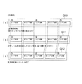
一方、この種のテープ印刷装置では、テープの長手方向に複数の段落を並べて印刷でき、各段落には入力されたキャラクタを並べたキャラクタ列を1行または複数行に亘って印刷でき、各行のキャラクタサイズを各行毎に任意に指定できるばかりでなく、行数が多い段落などに対する各行のサイズ指定の煩わしさを回避するため、図17に示すように、段落毎にその全ての行を一括してサイズ指定することができるようになっている。
【0005】
例えば、いわゆる「キャラクタサイズ均等モード」では、同図(a)に示すように、複数行(図示では3行)の全ての各行に対して、同一キャラクタサイズを、テープ幅と行数に応じて、自動的に設定する。
【0006】
また、「キャラクタサイズ一任モード」では、同図(b)に示すように、各行のキャラクタ列のキャラクタ数に従って、キャラクタ数の大きな行を小さなキャラクタサイズとして、長さのバランスが良くなるように、自動的に設定する(特開平7−125376号参照)。
【0007】
さらに、同図(c)の「キャラクタサイズメニューモード」では、例えば、「大中小」の抽象的かつ相対的なキャラクタサイズを選択して、1行目が「大」、2行目が「中」、および3行目が「小」のキャラクタサイズになるように、自動的に設定する(特開平6−143690号参照)。
【0008】
【発明が解決しようとする課題】
しかし、例えば上記のように段落毎に種々のサイズ設定モードの指定ができる従来のテープ印刷装置においても、印刷画像の元になる基礎画像を作成して、定長設定をした場合に、作成した基礎画像が設定された定長範囲(定長領域)に印刷不可能なときには、各段落等の区別無く、その設定された定長領域に合うように、一律に基礎画像を縮小することにより、その定長領域に印刷可能な印刷画像が作成され、印刷される。
【0009】
すなわち、種々のサイズ設定モード等を駆使して基礎画像を作成したにも拘らず、その基礎画像作成時のユーザの意図は、作成した基礎画像が設定された定長領域に印刷不可能なときには、無視されることになる。
【0010】
例えば、この従来のテープ印刷装置では、ビデオ等のタイトル部分を同一サイズに揃えたラベルを作製し、そのラベルを貼った複数のビデオ等を並べて保管したい場合でも、その重要なタイトル部分の段落が他の重要でない段落と同様に一律に縮小されるので、その結果、作製されるラベルのタイトル部分も縮小され、所望の当初の目的、すなわち、タイトル部分を同一サイズに揃えたラベルを作製する目的を満足することができない。
【0011】
本発明は、元になる基礎画像を予め設定された印刷領域内に印刷可能なように縮小しつつ、その縮小結果の印刷画像に基礎画像作成時の意図を反映させることができる、印刷画像作成方法およびその装置並びにその装置を備えた印刷装置を提供することを目的とする。
【0012】
【課題を解決するための手段】
本発明の印刷画像作成方法は、印刷対象物上の予め設定された印刷領域内に印刷するための印刷画像を作成する印刷画像作成方法であって、1以上の固定サイズ要素画像および1以上の可変サイズ要素画像から成る複数の要素画像を有する基礎画像を作成する基礎画像作成工程と、作成した前記基礎画像が複数の前記可変サイズ要素画像を有している場合に、各可変サイズ要素画像に対して、それぞれ重要度を設定する重要度設定工程と、前記基礎画像を前記印刷画像としたときに、前記印刷領域内に印刷不可能な場合、前記基礎画像の前記1以上の可変サイズ要素画像のうちの少なくとも1を縮小することにより、前記基礎画像を縮小した縮小画像を前記印刷画像として作成する基礎画像縮小工程と、を備え、前記基礎画像縮小工程は、前記可変サイズ要素画像に前記重要度が設定されている場合には、設定された前記重要度に応じて、前記可変サイズ要素画像を順次縮小することを特徴とする。
【0013】
また、本発明の印刷画像作成装置は、印刷対象物上の予め設定された印刷領域内に印刷するための印刷画像を作成する印刷画像作成装置であって、1以上の固定サイズ要素画像および1以上の可変サイズ要素画像から成る複数の要素画像を有する基礎画像を作成する基礎画像作成手段と、作成した前記基礎画像が複数の前記可変サイズ要素画像を有している場合に、各可変サイズ要素画像に対して、それぞれ重要度を設定する重要度設定手段と、前記基礎画像を前記印刷画像としたときに、前記印刷領域内に印刷不可能な場合、前記基礎画像の前記1以上の可変サイズ要素画像のうちの少なくとも1を縮小することにより、前記基礎画像を縮小した縮小画像を前記印刷画像として作成する基礎画像縮小手段と、を備え、前記基礎画像縮小工程は、前記可変サイズ要素画像に前記重要度が設定されている場合には、設定された前記重要度に応じて、前記可変サイズ要素画像を順次縮小することを特徴とする。
【0014】
この印刷画像作成方法およびその装置では、1以上の固定サイズ要素画像および1以上の可変サイズ要素画像から成る複数の要素画像を有する基礎画像を作成し、縮小の際には、可変サイズ要素画像のうちの少なくとも1を縮小するので、印刷可能なように基礎画像を縮小しても、固定サイズ要素画像のサイズは変わらない。
【0015】
このため、例えば重要な要素画像を固定サイズ要素画像、そうではない要素画像を可変サイズ要素画像とするなど、各要素画像の特性によってそれらを区別して基礎画像を作成すれば、基礎画像作成時の意図が、印刷画像にも反映される。
【0016】
したがって、この印刷画像作成方法およびその装置では、元になる基礎画像を予め設定された印刷領域内に印刷可能なように縮小しつつ、その縮小結果の印刷画像に基礎画像作成時の意図を反映させることができる。
【0017】
この場合、前記基礎画像作成工程は、前記複数の要素画像を作成する要素画像作成工程と、作成された各要素画像に対して、その要素画像が前記固定サイズ要素画像か前記可変サイズ要素画像かを含む要素画像サイズ特性を設定する要素画像サイズ特性設定工程と、を有することが好ましい。
【0018】
また、この場合、前記基礎画像作成手段は、前記複数の要素画像を作成する要素画像作成手段と、作成された各要素画像に対して、その要素画像が前記固定サイズ要素画像か前記可変サイズ要素画像かを含む要素画像サイズ特性を設定する要素画像サイズ特性設定手段と、を有することが好ましい。
【0019】
この印刷画像作成方法およびその装置では、作成された各要素画像に対して、その要素画像が固定サイズ要素画像か可変サイズ要素画像かを設定するので、例えば重要な要素画像を固定サイズ要素画像とし、そうではない要素画像を可変サイズ要素画像とするなど、各要素画像の要素画像サイズ特性を区別した基礎画像を作成できる。すなわち、これにより、基礎画像の各要素画像作成時のユーザ等の意図を、より明確に印刷画像にも反映させることができる。
【0020】
また、要素画像サイズ特性を、作成された各要素画像に対して設定できるので、印刷画像が所望の配置にならなかったり、印刷領域に印刷不可能であることが判明したときに、設定を変更することで対処することが可能になる。
【0021】
これらの場合において、前記1以上の可変サイズ要素画像の各可変サイズ要素画像の縮小は、所定の複数段階の縮小を含むことが好ましい。
【0022】
また、これらの場合において、前記1以上の可変サイズ要素画像の各可変サイズ要素画像の縮小は、所定の複数段階の縮小を含むことが好ましい。
【0023】
この印刷画像作成方法およびその装置では、各可変サイズ要素画像の縮小が所定の複数段階の縮小を含むので、各可変サイズ要素画像を徐々に縮小することができ、これにより、段階的に縮小した複数の縮小画像を得られる。
【0024】
この場合、前記要素画像縮小工程では、前記印刷領域に印刷可能となる縮小画像のうちの最大サイズの縮小画像を前記印刷画像として選択することが好ましい。
【0025】
また、この場合、前記要素画像縮小手段は、前記印刷領域に印刷可能となる縮小画像のうちの最大サイズの縮小画像を前記印刷画像として選択することが好ましい。
【0026】
この印刷画像作成方法およびその装置では、印刷領域に印刷可能となる縮小画像のうちの最大サイズの縮小画像を印刷画像として選択するので、印刷画像は、印刷領域に印刷可能な最も大きなサイズとなる。すなわち、大きくて見栄えが良い印刷画像を作成できる。
【0027】
これらの場合、前記複数段階の縮小において段階的に縮小した縮小画像のうちの最小サイズの縮小画像が前記印刷領域に印刷不可能なときに、その旨を報知することが好ましい。
【0028】
また、これらの場合、前記複数段階の縮小において段階的に縮小した縮小画像のうちの最小サイズの縮小画像が前記印刷領域に印刷不可能なときに、その旨を報知することが好ましい。
【0029】
この印刷画像作成方法およびその装置では、複数段階の縮小において段階的に縮小した縮小画像のうちの最小サイズの縮小画像が印刷領域に印刷不可能なときに、その旨を報知するので、ユーザは、最小サイズの縮小画像でも印刷領域に印刷不可能なことを知ることができる。これにより、ユーザは、異なる基礎画像や異なる設定に変更するなど、より早期に対処しやすくなる。
【0030】
なお、これらの印刷画像作成方法およびその装置において、基礎画像が前記可変サイズ要素画像を複数有する場合には、前記複数のうちの各縮小段階毎に、前記複数のうちの各1つの可変サイズ要素画像を順次縮小することが好ましい。
【0032】
この印刷画像作成方法およびその装置では、各可変サイズ要素画像のサイズの縮小段階が1であっても、その可変サイズ要素画像の数だけの縮小段階を経ることができ、その分の数の縮小画像を印刷画像の候補とできるので、きめ細かい縮小処理を行え、これにより、印刷領域により適した印刷画像を作成できる。
【0033】
また、これらの印刷画像作成方法およびその装置において、前記基礎画像が、前記可変サイズ要素画像を複数有する場合には、前記複数のうちの各縮小段階では、前記複数の可変サイズ要素画像を各1段階ずつ縮小してもよい。
【0035】
この印刷画像作成方法およびその装置では、一度の縮小段階で複数の可変サイズ要素画像を各1段階ずつ縮小するので、1縮小段階における縮小サイズを大きくでき、例えば基礎画像のサイズと印刷可能なサイズとがかけ離れているような場合に、縮小処理の高速化が図れる。
【0036】
これらのいずれかの印刷画像作成方法において、前記1以上の可変サイズ要素画像には、1以上のキャラクタ画像を有するものを含むとともに、キャラクタ画像は設定可能な複数のサイズを有しており、前記1以上のキャラクタ画像を有する可変サイズ要素画像の縮小には、各キャラクタ画像のサイズの縮小が含まれることが好ましい。
【0037】
また、これらのいずれかの印刷画像作成装置において、前記1以上の可変サイズ要素画像には、1以上のキャラクタ画像を有するものを含むとともに、キャラクタ画像は設定可能な複数のサイズを有しており、前記1以上のキャラクタ画像を有する可変サイズ要素画像の縮小には、各キャラクタ画像のサイズの縮小が含まれることが好ましい。
【0038】
この印刷画像作成方法およびその装置では、1以上の可変サイズ要素画像には、1以上のキャラクタ画像を有するものを含むとともに、キャラクタ画像は設定可能な複数のサイズを有しているので、この1以上のキャラクタ画像を有する可変サイズ要素画像の縮小においては、各キャラクタ画像のサイズを縮小することによって、可変サイズ要素画像の縮小を行なうことができる。通常、印刷装置等では、複数のキャラクタ画像のサイズを有するので、この場合、そのサイズを変更するだけで、容易に縮小処理を行うことができる。
【0039】
これらのいずれかの印刷画像作成方法において、前記1以上のキャラクタ画像を有する可変サイズ要素画像には、複数行を有するものを含み、その複数行を有する可変サイズ要素画像の縮小は、各行のキャラクタ画像のサイズが相対的に同一の比率となるように行われることが好ましい。
【0040】
また、これらのいずれかの印刷画像作成装置において、前記1以上のキャラクタ画像を有する可変サイズ要素画像には、複数行を有するものを含み、その複数行を有する可変サイズ要素画像の縮小は、各行のキャラクタ画像のサイズが相対的に同一の比率となるように行われることが好ましい。
【0041】
この印刷画像作成方法およびその装置では、1以上のキャラクタ画像を有する可変サイズ要素画像には、複数行を有するものを含み、その複数行を有する可変サイズ要素画像の縮小は、各行のキャラクタ画像のサイズが相対的に同一の比率となるように行われるので、その可変サイズ要素画像については、相対的な見た目が同一の縮小を行うことができ、その相対的な関係を設定(期待)したユーザの意図を、印刷画像に反映させることができる。
【0042】
これらのいずれかの印刷画像作成方法において、前記1以上の可変サイズ要素画像には、1以上のキャラクタ画像とその前後の少なくとも一方に設けられた余白画像とを有するものを含み、その可変サイズ要素画像の縮小には、前記余白画像のサイズの縮小が含まれることが好ましい。
【0043】
また、これらのいずれかの印刷画像作成装置において、前記1以上の可変サイズ要素画像には、1以上のキャラクタ画像とその前後の少なくとも一方に設けられた余白画像とを有するものを含み、その可変サイズ要素画像の縮小は、前記余白画像のサイズを縮小することによって行われることが好ましい。
【0044】
この印刷画像作成方法およびその装置では、1以上の可変サイズ要素画像が、複数のキャラクタ画像から成るキャラクタ列画像と各キャラクタ画像間の余白画像とを有するものを含んでいる場合には、その可変サイズ要素画像については、その余白画像を縮小するだけで、容易に縮小処理を行うことができる。
また、1以上の可変サイズ要素画像が、1以上のキャラクタ画像とその前後の余白画像を有するものを含んでいる場合には、その可変サイズ要素画像については、その余白画像を縮小するだけで、容易に縮小処理を行うことができる。
【0048】
これらのいずれかの印刷画像作成方法において、前記印刷対象物がテープであることが好ましい。
【0049】
また、これらのいずれかの印刷画像作成装置において、前記印刷対象物がテープであることが好ましい。
【0050】
この印刷画像作成方法およびその装置では、印刷対象物がテープなのでテープ印刷装置の印刷画像作成方法およびその装置として適用できる。
【0051】
なお、この場合の印刷画像作成方法において、前記基礎画像は、前記複数の要素画像を、前記テープの長手方向に相当する方向に並べて構成されることが好ましい。
【0052】
また、この場合の印刷画像作成装置において、前記基礎画像は、前記複数の要素画像を、前記テープの長手方向に相当する方向に並べて構成されることが好ましい。
【0053】
この印刷画像作成方法およびその装置では、基礎画像が各要素画像をテープの長手方向に相当する方向に並べて構成されているので、定長設定可能なテープ印刷装置などにおいて、定長範囲に印刷可能な印刷画像を作成する場合などに適したものとなる。
【0054】
これらの印刷画像作成方法および作成装置において、前記複数の要素画像の各要素画像は、それぞれテープ上に印刷される複数の段落のうちの1に対応することが好ましい。
【0056】
一般に、テープ印刷装置では、文章等の1のまとまりなどを1段落としてまとめるので、各段落の画像が表現する内容(趣旨)やその重要度等はそれぞれ相互に異なる。この印刷画像作成方法およびその装置では、前記複数の要素画像の各要素画像が、それぞれテープ上に印刷される複数の段落のうちの1に対応するので、各段落の画像を重要度等により区別して基礎画像を作成すれば、その縮小の際にも、各段落の趣旨や重要度等が印刷画像に反映され、それを作成したときの意図を明確に反映できる。
【0057】
これにより、例えばこの印刷画像作成方法およびその装置を適用したテープ印刷装置では、ビデオ等のタイトル部分を同一サイズに揃えたラベルを作製し、そのラベルを貼った複数のビデオ等を並べて保管したい場合に、重要なタイトル等の段落は固定サイズで揃え、日付などのメモ書き程度の情報の段落は可変サイズとすることにより、その意図を反映させた印刷画像を作成でき、それを印刷することにより、所望の(例えばタイトル部分を同一サイズに揃えた)ラベルを作製できる。
【0058】
また、本発明の印刷装置は、上記のいずれかに記載の印刷画像作成装置と、この印刷画像作成装置により作成された印刷画像を前記印刷領域内に印刷する印刷手段と、を備えたことを特徴とする。
【0059】
この印刷装置では、上記のいずれかの印刷画像作製装置を備えているので、これらで上述の各種利点を備え、基礎画像作成時の意図を反映させつつ、作成された印刷画像を予め設定された印刷領域内に印刷可能な印刷装置となる。
【0060】
【発明の実施の形態】
以下、本発明の一実施形態に係る印刷画像作成方法およびその装置並びにその装置を備えた印刷装置を適用したテープ印刷装置について、添付図面を参照しながら詳細に説明する。
【0061】
このテープ印刷装置1は、テープカートリッジ5を介して装置内に装着した印刷テープ(テープ)Tに、所望の文字や図形などを印刷(印字)すると共に、テープTの印刷済み部分を所定の長さに切断して、ラベルを作製するものである。
【0062】
図1はテープ印刷装置1の外観斜視図であり、同図に示すように、テープ印刷装置1は、上下2分割の装置ケース2により外殻が形成され、装置ケース2の前部上面には各種入力キーから成るキーボード3が配設されると共に、後部上面の左右にはそれぞれ開閉蓋21とディスプレイ4とが配設されている。
【0063】
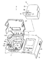
開閉蓋21の内側には、図2に示すように、テープカートリッジ5を装着するためのポケット6が設けられており、テープカートリッジ5はこの開閉蓋21を開放した状態でポケット6に対し着脱される。
【0064】
テープカートリッジ5には、一定の幅(4.5mm〜48mm程度)のテープTが内蔵されていて、相異なる幅等のテープTの種別を識別できるように、裏面に小さな複数の孔が設けられ、ポケット6には、この孔の有無を検出するマイクロスイッチなどのテープ識別センサ142(図4参照)が設けられていて、これにより、テープTの種別を検出できるようになっている。
【0065】
また、ポケット6には、環境(周囲)温度を検出して報告するサーミスタなどの周囲温度センサ143(図4参照)が設けられていて、周囲温度を検出して後述の制御部200に報告する。また、装置ケース2の左側部には、ポケット6と装置外部とを連通するテープ排出口22が形成され、テープ排出口22には、送りだしたテープTを切断するテープカッタ132が臨んでいる(図4参照)。
【0066】
テープ印刷装置1は、図4に示すように、基本的な構成として、キーボード3やディスプレイ4を有してユーザとのインタフェースを行う操作部11、サーマルヘッド7やテープ送り部120を有してポケット6内に装着したテープカートリッジ5のテープTに印刷を行う印刷部12、印刷後のテープTの切断を行う切断部13、各種センサを有して各種検出を行う検出部14、各種ドライバを有して各部回路を駆動する駆動回路部270、および、テープ印刷装置1内の各部を制御する制御部200を備えている。
【0067】
このため、装置ケース2の内部には、印刷部12、切断部13、検出部14などの他、図外の回路基板23が収納されている。この回路基板23には、電源ユニットの他、後述の駆動回路270や制御部200の各回路などが搭載され、外部から着脱可能なニッカド電池等の電池やACアダプタ接続口24に接続されている。
【0068】
テープ印刷装置1では、ユーザは、ポケット6にテープカートリッジ5を装着した後、キーボード3により所望のキャラクタ(文字、数字、記号、図形等)などの印刷画像の情報を入力し、同時にディスプレイ4により入力結果を確認すると共に編集を行う。
【0069】
その後、キーボード3を介して印刷を指示すると、テープ送り部120が駆動して、テープカートリッジ5からテープTを繰り出すと同時に、サーマルヘッド7が駆動して、テープTに所望の印刷を行う。
【0070】
そして、テープTの印刷済み部分は、印刷動作に並行してテープ排出口22から随時外部に送り出される。このようにして、所望の印刷が完了すると、テープ送り部120は、余白分を含むテープ長さの位置までテープTの送りを行った後、その送りを停止する。
【0071】
切断部13は、テープカッタ132と、任意長印刷などの場合に手動によりテープカッタ132を切断動作させるカットボタン133と、定長印刷などの場合に自動的にテープカッタ132を切断動作させるカッタモータ131と、を備えている(図4参照)。また、これにより、テープ印刷装置1では、モード設定によって、自動/手動を切り替えられるようにしている。
【0072】
このため、手動カットの場合、印刷が完了した時点で、ユーザが、装置ケース2の左後部に配設されたカットボタン133(図1、図2参照)を押すことで、テープカッタ132が作動しテープTが所望の長さに切断される。また、自動カットの場合、印刷が終了して余白分だけテープ送りされ、それが停止すると同時に、カッタモータ131が駆動され、テープTの切断が行われる。
【0073】
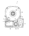
次に、印刷部12について説明する。図2および図3に示すように、テープカートリッジ5は、カートリッジケース51の内部にテープTとインクリボンRとを収容して、構成されており、その左下部には、ポケット6に配設されたヘッドユニット61に差し込むための貫通孔55が形成されている。また、テープTとインクリボンRとが重なる部分には、ヘッドユニット61に内蔵されたサーマルヘッド7に対応して、プラテンローラ56が収納されている。
【0074】
一方、テープカートリッジ5に対応してポケット6には、プラテンローラ56に係合してこれを回転させるプラテン駆動軸62と、リボン巻取りリール54に係合してこれを回転させる巻取り駆動軸63と、位置決めピン64とが、それぞれ立設されている。
【0075】
テープカートリッジ5がポケット6に装着されると、ヘッドユニット61にテープカートリッジ5の貫通孔55が、位置決めピン64にテープリール52(の中心孔52a)が、プラテン駆動軸62にプラテンローラ56(の中心孔56a)が、巻取り駆動軸63にリボン巻取りリール54(の中心孔54a)が、それぞれ差し込まれ、テープTおよびインクリボンRの送りが可能になる。また、この状態で開閉蓋21を閉塞すると、テープTおよびインクリボンRを挟み込んでサーマルヘッド7がプラテンローラ56に当接して、印刷が可能になる。
【0076】
テープTはテープリール52から繰り出され、インクリボンRは、リボンリール53から繰り出され、テープTと重なって併走した後、リボン巻取りリール54に巻き取られる。すなわち、プラテンローラ56とリボン巻取りリール54とが同期して回転することにより、テープTとインクリボンRとが同時に送られ、かつこれらに同期してサーマルヘッド7が駆動することで、印刷が行われる。
【0077】
また、印刷完了後、プラテンローラ56の回転(リボン巻取りリール54も同期回転する)が所定時間続行することで、テープTの送りが続行されその所定の切断位置がテープカッタ132の位置まで送られる。
【0078】
なお、サーマルヘッド7の表面に密着してサーミスタなどのヘッド表面温度センサ144(図4参照)が設けられていて、サーマルヘッド7の表面温度を検出して後述の制御部200に報告する。
【0079】
テープ送り部120は、ポケット6の側方に配設したDCモータ121(図4参照)を動力(駆動)源として、上記のプラテン駆動軸62および巻取り駆動軸63を回転させるものであり、ポケット6の側方から下方に亘る空間に配設されている。
【0080】
テープ送り部120は、このDCモータ121と、プラテン駆動軸62と、巻取り駆動軸63と、DCモータ121の回転数を検出するためのエンコーダ122(図4参照)と、DCモータ121の動力を各駆動軸に伝達する図外の減速歯車列と、これらを支持するシャーシとを備えている。
【0081】
また、エンコーダ122は、円盤状の周方向の4箇所に検出開口が形成され、DCモータ121の主軸の先端に固着されている(ここでは、便宜上、下記の回転速度センサ141を除いた円盤部分のみを「エンコーダ」という)。
【0082】
検出部14は、図4に示すように、前述のテープ識別センサ142、周囲温度センサ143、ヘッド表面温度センサ144の他、DCモータ121の回転速度を検出する回転速度センサ141を備えている。なお、後述のように、実状に合わせて、これらを省略した構成とすることもできる。
【0083】
この回転速度センサ141は、上述のエンコーダ122の検出開口に臨む図外のフォトセンサと、フォトセンサを支持すると共にその間で光電変換を行うセンサ回路基板とを備えている。フォトセンサには、図外の発光素子と受光素子とが対向配置され、発光素子の光が回転するエンコーダ122(の円盤周方向)の検出開口を通過して受光素子に受光されることにより、DCモータ121の回転数(パルス数)が検出される。すなわち、受光素子で受光された光の明滅が、センサ回路基板により光電変換され、パルス信号として後述の制御部200に出力される。
【0084】
駆動回路部270は、図4に示すように、ディスプレイドライバ271と、ヘッドドライバ272と、モータドライバ273とを備えている。
【0085】
ディスプレイドライバ271は、制御部200から出力される制御信号に基づき、その指示に従って、操作部11のディスプレイ4を駆動する。同様に、ヘッドドライバ272は、制御部200の指示に従って、印刷部12のサーマルヘッド7を駆動する。
【0086】
また、モータドライバ273は、印刷部12のDCモータ121を駆動するDCモータドライバ273dと、切断部13のカッタモータ131を駆動するカッタモータドライバ273cとを有し、同様に、制御部200の指示に従って、各モータを駆動する。
【0087】
操作部11は、キーボード3とディスプレイ4とを備えている。ディスプレイ4は、横方向(X方向)約6cm×縦方向(Y方向)4cmの長方形の形状の内側に、96ドット×64ドットの表示画像データを表示可能な表示画面41を有し、ユーザがキーボード3からデータを入力して、キャラクタ列画像データなどの印刷画像データを作成・編集したり、その結果等を視認したり、キーボード3から各種指令・選択指示等を入力したりする際などに用いられる。
【0088】
キーボード3には、図外のアルファベットキー群311、記号キー群312、数字キー群313、平仮名や片仮名等の仮名キー群314、および外字を呼び出して選択するための外字キー群315等を含む文字キー群31の他、各種の動作モードなどを指定するための機能キー群32などが配列されている。
【0089】
機能キー群32には、図外の電源キー321、印刷動作を指示するための印刷キー322、テキスト入力時のデータ確定や改行および選択画面における各種モードの選択指示のための選択キー323、印刷画像データの印刷色やその中間色(混色)を指定するための色指定キー324、文字色や背景色を設定するための色設定キー325、並びに、それぞれ上(「↑」)、下(「↓」)、左(「←」)、右(「→」)方向へのカーソル移動や表示画面41の表示範囲を移動させるための4個のカーソルキー330(330U、330D、330L、330R:「カーソル「↑」キー330U」など)が含まれる。
【0090】
機能キー群32には、さらに、各種指示を取り消すための取消キー326、各キーの役割を変更したり、描画登録画像データの修正等に用いられるシフトキー327、テキスト入力画面や選択画面と印刷画像データの表示画面(イメージ画面)とを相互に切り換えるためのイメージキー328、印刷画像データとイメージ画面に表示する表示画像データとの大きさの比率を変更するための比率変更(ズーム)キー329、並びに、作製するラベルの各種書式やスタイルを設定するためのスタイルキー341が含まれる。
【0091】
なお、当然ながら、一般的なキーボードと同様に、これらのキー入力は、各キー入力毎に個別にキーを設けて入力しても良いし、シフトキー327等と組み合わせてより少ない数のキーを用いて入力しても良い。ここでは、理解を容易にするために上記の分だけキーがあるものとする。
【0092】
図4に示すように、キーボード3は、上述のような種々の指令およびデータを制御部200に入力する。
【0093】
制御部200は、CPU210、ROM220、キャラクタジェネレータROM(CG−ROM)230、RAM240、周辺制御回路(P−CON)250を備え、互いに内部バス260により接続されている。
【0094】
ROM220は、CPU210で処理する制御プログラムを記憶する制御プログラム領域221の他、文字サイズテーブルや文字修飾テーブルなどを含む制御データを記憶する制御データ領域222を有している。
【0095】
CG−ROM230は、テープ印刷装置1に用意されている文字、記号、図形等のフォントデータを記憶していて、文字等を特定するコードデータが与えられたときに、対応するフォントデータを出力する。
【0096】
RAM240は、電源キー321の操作により電源がオフにされても、記憶したデータを保持しておくように図外のバックアップ回路によって電源の供給を受けており、各種レジスタ群241や、ユーザがキーボード3から入力した文字等のテキストデータを記憶するテキストデータ領域242、表示画面41の表示画像データを記憶する表示画像データ領域243、印刷画像データを記憶する印刷画像データ領域244、描画登録画像データを記憶する描画登録画像データ領域245の他、印刷履歴データ領域246やその他の色変換バッファなどの各種変換バッファ領域247などの領域を有し、制御処理のための作業領域として使用される。
【0097】
P−CON250には、CPU21の機能を補うとともに周辺回路とのインタフェース信号を取り扱うための論理回路が、ゲートアレイやカスタムLSIなどにより構成されて組み込まれている。例えば種々の計時を行うタイマ251などもP−CON250内の機能として組み込まれている。
【0098】
このため、P−CON250は、検出部14の各種センサやキーボード3と接続され、検出部14からの前述した各種検出信号およびキーボード3からの各種指令や入力データなどをそのままあるいは加工して内部バス260に取り込むとともに、CPU210と連動して、CPU210等から内部バス260に出力されたデータや制御信号を、そのままあるいは加工して駆動回路部270に出力する。
【0099】
そして、CPU210は、上記の構成により、ROM220内の制御プログラムに従って、P−CON250を介して各種検出信号、各種指令、各種データ等を入力し、CG−ROM230からのフォントデータ、RAM240内の各種データ等を処理し、P−CON250を介して駆動回路部270に制御信号を出力することにより、印刷の位置制御や表示画面41の表示制御等を行うとともに、サーマルヘッド7を制御して所定の印刷条件でテープTに印刷するなど、テープ印刷装置1全体を制御している。
【0100】
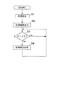
次に、テープ印刷装置1の制御全体の処理フローについて、図5を参照して説明する。電源オン等により処理が開始すると、同図に示すように、まず、テープ印刷装置1を、前回の電源オフ時の状態に戻すために、退避していた各制御フラグを復旧するなどの初期設定を行い(S1)、次に、前回の表示画面を初期画面として表示する(S2)。
【0101】
図5のその後の処理、すなわちキー入力か否かの判断分岐(S3)および各種割込処理(S4)は、概念的に示した処理である。実際には、テープ印刷装置1では、初期画面表示(S2)が終了すると、キー入力割込を許可し、キー入力割込が発生するまでは、そのままの状態を維持し(S3:No)、何らかのキー入力割込が発生すると(S3:Yes)、それぞれの割込処理に移行して(S4)、その割込処理が終了すると、再度、その状態を維持する(S3:No)。
【0102】
上述のように、テープ印刷装置1では、主な処理を割込処理により行うので、印刷対象となる印刷画像データができていれば、ユーザが任意の時点で印刷キー322を押すことにより、印刷処理割込が発生して、印刷処理が起動され、その印刷画像データによる印刷ができる。すなわち、印刷に至るまでの操作手順は、ユーザが任意に選択できる。
【0103】
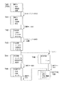
まず、図6〜図8を参照して、文字サイズの選択・設定方法について説明する。図6に示すように、テキスト入力画面表示(画面T10:以下、表示画面41の表示状態を画面T××で表現し、参照番号としてはT××のみで示す。)のときに、スタイルキー341を押すと、印刷するときの所定の書式・スタイル関係の選択・設定が可能になる(T11)。
【0104】
すなわち、▲1▼「文字サイズ」、▲2▼「割付け」、▲3▼「外枠・表組」の3つのうちのいずれか1つを、カーソル「↓」キー330D(若しくはカーソル「→」キー330R)またはカーソル「↑」キー330U(若しくはカーソル「←」キー330L)の操作によって反転表示(図示では点による網掛けで示す。)させ、選択キー323を押すことによって、反転表示されたものを選択・指定することができる。
【0105】
同図に示すように、スタイルキー341を押した直後はデフォルトの▲1▼「文字サイズ」が反転表示されているので、この状態(T11)で、選択キー323を押すと、「文字サイズ」が選択され、文字サイズの各設定方法が選択可能になる(T12)。
【0106】
文字サイズの設定方法としては、図7に示すように、第1階層の選択枝の▲1▼文字サイズの下位階層として、第2階層には、図17の従来技術で前述の「キャラクタサイズ均等モード」に相当する▲1▼均等、「キャラクタサイズ一任モード」に相当する▲2▼「自動らくらく」、「キャラクタサイズメニューモード」およびそれを改良した「キャラクタサイズフリーモード」のために指定する▲3▼「行数」の選択枝があり、▲3▼「行数」の下位階層として、第3階層には、「キャラクタサイズメニューモード」の▲1▼各メニューと、「キャラクタサイズフリーモード」に相当する▲2▼「自由のびのび」の選択枝がある。
【0107】
例えば、図6の文字サイズの選択枝を表示した状態(T12)で、カーソル「↓」キー330D(若しくはカーソル「→」キー330R)またはカーソル「↑」キー330U(若しくはカーソル「←」キー330L)により第2階層の▲3▼行数の2行を反転表示させて(T13)、選択キー323を押すと、第3階層が表示される(T14)ので、同様に、▲2▼「自由のびのび」を反転表示させて(T15)、選択キー323を押すと、▲2▼「自由のびのび」の入力画面表示となる(以下、省略)。一方、画面T14の状態から、取消キー326を押せば、上位階層の第2階層に戻すことができる(T16)。
【0108】
各行のメニューや「自由のびのび」による各行の文字サイズ設定が終了して選択キー323を押すと、第1階層に戻る(T17)。また、前述の▲2▼自由らくらくを反転表示させた状態(T12)で、選択キー323を押すと、「自動らくらく」が設定され、同様に第1階層に戻る(T17)。
【0109】
図8に示すように、この状態(T17:図7と共通)で、カーソル「↓」キー330Dまたはカーソル「→」キー330Rを押すと、「外枠・表組」が反転表示され(T18)、さらに同じ操作をすると、「終わり?」が反転表示される(T19)。
【0110】
この状態(T19)で、選択キー323を押すと、有効範囲の入力が促されるので(T20〜T21)、例えば、「この段落」を反転表示(指定)して選択キー323を押すと、文字サイズを含む書式・スタイル関係の設定が終了して、テキスト入力画面に戻る(T22:図7のT10と同じ)。
【0111】
この場合、カーソルKが位置する段落に文字サイズ(のモード)が設定されることになり、内部(制御部200)では、テキスト入力画面に戻ると同時に、設定されたモードに従って文字サイズを算出して、対応する印刷画像を作成する。
【0112】
次に、定長/任意長の選択・設定および、それらにおけるキャラクタ列画像などから成る印刷画像の割付スタイルの選択・設定の方法について説明する。
【0113】
例えば、図6で上述の状態(T10)で、すなわちテキスト入力画面の表示状態で、同様に、スタイルキー341を押し、書式・スタイルの選択画面の表示状態(T11)で、図9で示すように、割付処理を行うための▲2▼「割付け」を反転表示させ(T30:図6や図8のT17と同じ表示)、選択キー323を押すと、割付処理の際の定長/任意長および変更の選択画面が表示される(T31)。
【0114】
なお、定長については後述するので、以下では、まず、任意長について説明する。
【0115】
この状態(T30)で、「任意長」を反転表示させて(T31)、選択キー323を押すと、任意長における割付スタイルの選択画面が表示される(T32)。
【0116】
この状態(T32)では、割付スタイルとして、▲1▼キャラクタ列画像の各キャラクタ画像間を等間隔とする均等割付処理を指定する「均等」、▲2▼所定範囲の左端にキャラクタ列画像の左端を揃える左端揃え処理を指定する「左端」、▲3▼所定範囲の右端にキャラクタ列画像の右端を揃える右端揃え処理を指定する「右端」、▲4▼所定範囲の中心にキャラクタ列画像の中心を揃えるセンター揃え処理を指定する「センター」、▲5▼キャラクタ列画像の長さが所定範囲に合うように各キャラクタ画像を拡大する拡大処理または縮小する縮小処理を指定する「拡大/縮小」、……などの選択枝のいずれかを選択できる。
【0117】
ここでは、一例として▲2▼「左端」を反転表示させて(T32)、選択キー323を押すと、前述の書式・スタイルの選択画面に戻る(T33:図8のT18と同じ)。この状態(T33)で前述と同様に、「終わり?」を反転表示させて(T34:T19と同じ)、選択キー323を押すと、有効範囲が促されるので(T35:T20と同じ)、ここでは、例えば「この文章」を反転表示させ(T35)、選択キー323を押すと、書式・スタイルの選択・設定が終了して、テキスト入力画面に戻る(図8のT22と同様)。
【0118】
この場合、テキスト入力画面に戻ると同時にカーソルKの位置する段落ではなく、文章全体、すなわち印刷画像全体を任意長に設定するので、前述の文字サイズの設定モード等に従った印刷画像は、そのまま生かされる。
【0119】
次に定長の選択・設定の方法について説明する。
【0120】
図6で前述のように、スタイルキー341を押した直後は、デフォルトの▲1▼「文字サイズ」が反転表示されている(図6のT11)ので、それを▲2▼「割付け」の反転表示にして(図9のT30)、選択キー323を押すと、割付処理の際の定長/任意長および変更の選択画面が表示される(図9のT31)。
【0121】
図10に示すように、その状態(T40:図9のT31と同じ)から、カーソル「↑」キー330Uを操作して、「定長」を反転表示させ(T41)、選択キー323を押すと、前述の「任意長」を選択した場合と異なり、定長設定の選択画面が表示される(T42)。
【0122】
この状態(T42)では、▲1▼定長設定を中止する「しない」、▲2▼定型の長さとして、A4ファイル用のラベルの幅(ここでは20cmを想定)を指定する「A4ファイル」、▲3▼同様に、B5ファイル用(15cm)を指定する「B5ファイル」、▲4▼5.25FD用(8.5cm)を指定する「5.25FD」、▲5▼3.5FD用(6.5cm)を指定する「3.5FD」、▲6▼VHS/β用(14cm)を指定する「VHS/β」、▲7▼8mmビデオ用(7cm)を指定する「8mmビデオ」、▲8▼音楽テープ用(9.5cm)を指定する「音楽テープ」、……などの選択枝のいずれかを選択できる(T42〜T44)。
【0123】
ここでは、一例として▲2▼「8mmビデオ」を反転表示させて(T44)、選択キー323を押すと、定長における割付スタイルの選択画面が表示される(T45)。
【0124】
なお、テープ印刷装置1では、上記のような定型の長さばかりでなく、例えば上述の定長設定の選択画面が表示された状態(T42〜T44)で、キーボード3で前述の数値キー群313のいずれか(例えば「7」キー)を押すと、その数値(「7」)により「7cm」が定長として設定される(T46)。
【0125】
割付スタイル設定以降(T47以降:図8のT18以降や図9のT33以降と同じ)については、前述と同様なので、詳細な説明は省略するが、テープ印刷装置1では、定長を設定した場合、テキスト入力画面に戻る(図8のT22と同様)と同時に、定長設定割込が発生して、図11に示す定長処理が起動され、それぞれキャラクタ画像などから成る段落(要素画像)を有する印刷画像の長さ(印刷長値)がその定長範囲(印刷領域)の長さ(定長設定値)となるように、印刷画像の各段落(各要素画像)のサイズを調整(縮小)して割り付ける。
【0126】
以下、定長処理について、その処理の概要や具体例を図12〜図15を参照して補足しつつ、図11を参照して説明する(以下、印刷画像データをG××で、それを印刷したときの印刷イメージをM××で、それをカットしてラベルとしたときのラベルイメージをR××で表現し、それらの参照番号で図示するが、それらが同等の場合G××(M××、R××)等と略す)。
【0127】
まず、図12に示すように、例えば1、3、5段落目(図示の▲1▼、▲2▼、▲3▼の段落)を、図17(b)で前述の「キャラクタサイズ一任モード」に相当する「自動らくらく」に設定された段落(図示では「らく2 段落」と表示)、他の2、4段落目をその他の文字サイズのモードに設定された段落(図示では「非らく2 段落」と表示)とする5段落構成の印刷画像データG10を、定長設定値に合わせて縮小する場合、ここでは、「自動らくらく」に設定された段落(らく2 段落)を可変サイズ段落(可変サイズ要素画像)、その他の段落を固定サイズ段落(固定サイズ要素画像)として扱う。
【0128】
上記の「自動らくらく」のモードは、いわゆる「キャラクタサイズ一任モード」に相当するため、「らく2 段落」は、その段落自体の体裁さえ整えば良い段落、すなわち、他のモードに設定された段落と比べ、その文字等の配置にユーザの意図が最も反映されていない段落と見ることができる。
【0129】
例えば、ユーザがこのテープ印刷装置1を使用して、ビデオ等のタイトル部分を同一サイズに揃えたラベルを作製し、そのラベルを貼った複数のビデオ等を並べて保管したい場合、そのタイトル部分の段落に、文字サイズをテープ印刷装置1に一任する「自動らくらく」のモードを設定することは考えにくい。
【0130】
逆に言えば、重要なタイトル部分の段落には他のモードを設定し、印刷後に読み取れさえすれば良いような日付などのメモ書き程度の情報の段落には、その文字サイズの設定が面倒なので可変サイズ段落の設定となる「自動らくらく」のモードを設定する、などの利用方法が想定される。
【0131】
もちろん、他のモードを上記の「自動らくらく」と同様に、可変サイズ段落の設定とすることもできるが、以下の説明では、「自動らくらく」に設定された段落(らく2 段落)を可変サイズ段落(可変サイズ要素画像)、その他のモードに設定された段落(非らく2 段落)を固定サイズ段落(固定サイズ要素画像)として説明する。
【0132】
定長が設定され、テキスト入力画面に戻ると同時に、定長設定割込が発生して、定長処理が起動されると、図11に示すように、まず、ユーザが作成した基礎画像を印刷する場合の長さ(印刷長値)、すなわち定長が設定されていない(任意長の)場合や基礎画像の定長範囲内に収まる場合にそのまま印刷するときの長さ(以下「任意長の印刷長」)を算出し(S11)、定長設定値と比較する(S12)。
【0133】
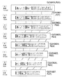
例えば、図14(a)は、任意長の印刷長が13.1cm、段落数N=4の印刷画像の一例、図15(a)は、任意長の印刷長が16.8cm、段落数N=5の印刷画像の一例を示し、図14(b)〜(h)や図15(b)〜(g)は、種々の定長設定を行った場合の印刷画像の例を示している。これらの場合、上記の印刷長値算出(S11)では、それぞれ13.1[cm]、16.8[cm]が算出されることになる。
【0134】
任意長のときの、すなわち基礎画像作成直後の当初の印刷長値と定長設定値と比較し(S12)、その印刷長値が定長設定値以下であれば(S12:No)、基礎画像をそのまま印刷しても、所定の印刷領域に収まるので、そのまま定長処理を終了する(S24)。この後には、ユーザが任意の時点で印刷キー322を押すことにより、基礎画像(例えば、図14(a)の印刷画像データG20(M20、R20)、図15(a)の印刷画像データG30(M30、R30))を印刷画像としてそのまま印刷できる。
【0135】
一方、基礎画像の印刷長値が定長設定値を越えているとき(S12:Yes)には、次に、変数iおよびNを初期化(i=1、N=段落数)する(S13)。例えば、図12の基礎画像(印刷画像データG10)が定長設定値を越えているとき(S12:Yes)には、次に、変数iおよびNを初期化(i=1、N=5)する(S13)。
【0136】
変数i、Nの初期化を終了すると(S13)、次に、所定の段階数(ここでは5と規定している)まで縮小を終了したか否かを判別する(S14)。
【0137】
ここで、所定の段階まで終了しているとき、すなわち、所定の段階数である5段階目(図13参照)まで縮小しても、まだ、定長設定値以下とならないとき(S14:Yes)には、設定した定長範囲(すなわち所望の印刷領域)には印刷できない(印刷不可能である)ことをユーザに報知するために、ディスプレイ4の表示画面41に「定長字余り」のエラーを表示して(S23)、処理を終了する(S24)。
【0138】
一方、所定の5段階目の縮小まで終了していないとき(S14:No)には、変数nに段落数N(例えば図12の例ではN=5)を代入し(S15)、次に、n段落目(5段落目)が「らく2 段落」か否かを判別する(S16)。
【0139】
図12の例では、前述のように、5段落目が「らく2 段落」なので(G10の▲3▼)、このようなとき(S16:Yes)には、次に、その段落をi段階目(最初はi=1)のキャラクタサイズに変更する(S17)。
【0140】
テープ印刷装置1では、図13に示すように、基礎画像のキャラクタサイズを基本サイズとしたときに、i(=1〜5)段階目の縮小ではどのサイズにするかを規定している。
【0141】
なお、念のため、この場合のキャラクタサイズのキャラクタは、文字、数字、記号、簡易図形等の他、外字登録等や描画登録等で登録した少し複雑な図形等も含む概念であり、キャラクタ画像は、それらのキャラクタをドットマトリクス等により構成した画像である。
【0142】
すなわち、この縮小処理(S17)では、各キャラクタ画像のサイズを縮小することによって、可変サイズ段落(可変サイズ要素画像)である「らく2 段落」の縮小を行なうことができる。
【0143】
図12の例では、前述のように、5段落目が「らく2 段落」なので(G10の▲3▼)、この縮小処理により、まず、この5段落目をi段階目、すなわち最初は図13の1段階目(i=1)のキャラクタサイズに変更する(S17)。
【0144】
なお、テープ印刷装置1以外の印刷装置等でも、通常、複数のキャラクタ画像のサイズを有するので、これらの場合、そのキャラクタサイズを変更するだけで、容易に縮小処理を行うことができる。
【0145】
また、テープ印刷装置1では、可変サイズ段落(可変サイズ要素画像)の「らく2 段落」が複数行を有する場合、図13に示すように、各行のサイズが相対的に同一の比率となるように縮小する。
【0146】
例えば1行目がMサイズ、2行目がSサイズの2行を有する場合(図中のM+Sの欄)、1行目が縮Mサイズ、2行目が縮Sサイズ(図中の縮M+縮S)とし、元の比率M/Sと等しい(すなわちM/S=縮M/縮S)比率で縮小する。
【0147】
すなわち、テープ印刷装置1では、複数行を有する可変サイズ段落(可変サイズ要素画像)の縮小を、各行のキャラクタ画像のサイズが相対的に同一の比率となるように行うので、その可変サイズ段落(可変サイズ要素画像)については、相対的な見た目が同一の縮小を行うことができ、基礎画像作成時にその相対的な関係を設定(期待)したユーザの意図を、印刷画像に反映させることができる。
【0148】
なお、上述の説明では、キャラクタ画像のサイズについてのみ説明したが、各キャラクタ画像間に余白(余白画像)がある場合、その可変サイズ段落(可変サイズ要素画像)については、その余白画像だけを縮小するようにして容易に縮小処理を行うこともできる。また、キャラクタ画像のサイズとともに縮小してもよい。
【0149】
また、キャラクタ画像の前後に余白画像を有する場合も同様であり、その可変サイズ段落(可変サイズ要素画像)については、その余白画像を縮小するだけで、容易に縮小処理を行うことができる。もちろん、上記のキャラクタ画像のサイズや各キャラクタ画像間の余白画像とともに縮小することもできる。
【0150】
上述の縮小処理が終了すると(S17)、次に、その時点での印刷長値を算出する(S18)。この時点では、例えば前述の図12の例では、5段落目の「らく2 段落」(G10の▲3▼)が1段階目のキャラクタサイズに変更され(S17)、縮小されている(G11の▲3▼)。
【0151】
次に、その印刷長値と定長設定値と比較し(S19)、その印刷長値が定長設定値以下であれば(S19:No)、その時点での縮小画像(例えば図12の印刷画像データG11)を印刷画像として印刷すれば、所定の印刷領域に収まるので、定長処理を終了する(S24)。
【0152】
この後には、前述のように、ユーザが任意の時点で印刷キー322を押すことにより、その縮小画像を印刷画像として印刷領域内に印刷できる。
【0153】
一方、その時点で印刷長値が定長設定値を越えているとき(S19:Yes)には、次に、変数nを更新(デクリメント:n←n−1)して(S20)、その変数nが0となったか否か、すなわち全ての段落に対して縮小処理されたか否かを判別し(S21)、終了していないとき(S21:No)には、新たなn段落目が「らく2 段落」か否か、すなわち可変サイズ段落(可変サイズ要素画像)か否かを判別する(S16)。
【0154】
この時点では、例えば前述の図12の例では、変数nの更新(n=5−1=4)により、4段落目が新たにn段落目になり(S20)、その4段落目は「非らく2 段落」(G11の▲2▼と▲3▼の間の段落)なので、このようなとき(S16:No)には、縮小をせずに、次に、再度、変数nの更新(n=4−1=3)をし(S20)、全ての段落について終了したか否か(n≦0)を判別し(S21)、終了していないとき(S21:No)には、新たなn段落目(3段落目)が「らく2 段落」の可変サイズ段落(可変サイズ要素画像)か否かを判別する(S16)。
【0155】
そして、この時点で対象となる図12の3段落目は「らく2 段落」(G11の▲2▼)なので、上述の5段落目と同様に、1段階目(図13参照)のキャラクタサイズに変更する縮小処理を行い(S17)、その時点での縮小画像(図12のG12)の印刷長値を算出し(S18)、その印刷長値が定長設定値以下であれば(S19:No)、その縮小画像(G12)を印刷画像として印刷すれば、所定の印刷領域に収まるので、定長処理を終了する(S24)。
【0156】
一方、その時点で印刷長値が定長設定値を越えているとき(S19:Yes)には、変数nの更新(n=3−1=2)をし(S20)、全ての段落について終了したか否か(n≦0)を判別する(S21)。
【0157】
以上のループ処理による縮小処理を行い(S16〜S21)、変数nの更新(n=5、4、3、2、1)の全ての段落について終了(n≦0)となる(S21:Yes)までの間に、その間に作成した縮小画像の印刷長値が定長設定値以下となれば(S19:No)、その縮小画像を印刷画像として印刷すれば、所定の印刷領域に収まるので、定長処理を終了する(S24)。
【0158】
そして、その後には、前述のように、ユーザが任意の時点で印刷キー322を押すことにより、その縮小画像を印刷画像として印刷領域内に印刷できる。
【0159】
一般に、テープ印刷装置では、文章等(数字、記号、簡易図形等の他、外字登録等された少し複雑な図形等を含む)の1つのまとまりなどを1つの段落としてまとめるので、各段落の画像が表現する内容(趣旨)やその重要度等はそれぞれ相互に異なる。
【0160】
上述のように、このテープ印刷装置1では、ユーザが作成した元の基礎画像(例えば印刷画像データG10)を構成する複数の各要素画像が、それぞれテープT上に印刷される複数の段落のうちの1に対応するので、各段落の画像を重要度等により区別して基礎画像を作成し、また、各段落にその重要度に応じた設定をすれば、その縮小の際にも、各段落の趣旨や重要度等が印刷画像に反映され、それを作成したときの意図を明確に反映できる。
【0161】
これにより、例えばビデオ等のタイトル部分を同一サイズに揃えたラベルを作製し、そのラベルを貼った複数のビデオ等を並べて保管したい場合に、重要なタイトル等の段落には他のモードを設定して固定サイズで揃え、日付などのメモ書き程度の情報の段落には「自動らくらく」モードを設定して可変サイズとすることにより、その意図を反映させた印刷画像を作成でき、それを印刷することにより、所望の(例えばタイトル部分を同一サイズに揃えた)ラベルを作製できる。
【0162】
ところで、上述のループ処理による縮小処理(S16〜S21)によって、変数nの更新(n=5、4、3、2、1)の全ての段落について終了(n≦0)となる(S21:Yes)までの間に、その間に作成した縮小画像の印刷長値が定長設定値以下とならなかったとき(S19:Yes)には、全ての段落について終了(n≦0)と判別され(S21:Yes)、次に、変数iを更新(インクリメント:i←i−1)して(S22)、再度、5段階目(所定の段階数)まで縮小を終了したか否かを判別する(S14)。
【0163】
ここで、所定の5段階目の縮小まで終了していないとき(S14:No)には、変数nに段落数N(例えば図12の例ではN=5)を代入し(S15)、次のn段落目(5段落目)が「らく2 段落」か否かの判別からのループ処理による縮小処理を行う(S16〜S21)。
【0164】
この場合、図13で参照するサイズは、2(=i=1+1)段階目のサイズとなり、それでも、その間に作成した縮小画像の印刷長値が定長設定値以下とならなかったとき(S19:Yes)には、変数iをさらに更新(i=2+1=3)して(S22)、同様のループ処理(S14〜S22)を行う。
【0165】
そして、変数iを更新して(i=1、2、3、4、5)、上記のループ処理(S14〜S22)を行い、所定の5段階目(図13参照)まで縮小(S14:Yes)するまでの間に、その間に作成した縮小画像の印刷長値が定長設定値以下となれば(S19:No)、その縮小画像を印刷画像として印刷すれば、所定の印刷領域に収まるので、定長処理を終了する(S24)。
【0166】
そして、その後には、前述のように、ユーザが任意の時点で印刷キー322を押すことにより、その縮小画像を印刷画像として印刷領域内に印刷できる。
【0167】
上述のように、このテープ印刷装置1では、各可変サイズ段落(各可変サイズ要素画像)の縮小が所定の複数段階の縮小を含むので、各可変サイズ段落(各可変サイズ要素画像)を徐々に縮小することができ、これにより、段階的に縮小した複数の縮小画像を得られる。
【0168】
また、テープ印刷装置1では、徐々に縮小(複数段階で段階的に縮小)した縮小画像が印刷長値が定長設定値以下となったときに(S19:No)、定長処理を終了する(S24)。すなわち、複数段階で段階的に縮小すれば複数の縮小画像が得られるが、印刷領域に印刷可能となる縮小画像のうちの最大サイズの縮小画像を印刷画像として選択することになる。そして、これにより、選択された印刷画像は、印刷領域に印刷可能な最も大きなサイズとなる。すなわち、大きくて見栄えが良い印刷画像を作成できる。
【0169】
一方、変数iを更新して(i=1、2、3、4、5)、所定の5段階目まで縮小しても(図13参照)、まだ、定長設定値以下とならないとき(S14:Yes)には、前述のように、設定した定長範囲(すなわち所望の印刷領域)には印刷できない(印刷不可能である)ことをユーザに報知するために、「定長字余り」のエラーを表示して(S23)、定長処理を終了する(S24)。
【0170】
すなわち、テープ印刷装置1では、複数段階の縮小において段階的に縮小した縮小画像のうちの最小サイズの縮小画像が印刷領域に印刷不可能なときに、その旨を報知するので、ユーザは、最小サイズの縮小画像でも印刷領域に印刷不可能なことを知ることができる。これにより、ユーザは、異なる基礎画像や異なる設定に変更するなど、より早期に対処しやすくなる。
【0171】
また、テープ印刷装置1では、各可変サイズ段落(各可変サイズ要素画像)のサイズの縮小段階が1であっても、(例えば図12のG10→G11→G12→……のように、)その可変サイズ段落(可変サイズ要素画像)の数(図12の例では▲3▼〜▲1▼の3つ)の縮小段階を経ることができ、その分の数の縮小画像を印刷画像の候補とできるので、きめ細かい縮小処理を行え、これにより、印刷領域により適した印刷画像を作成できる。
【0172】
なお、この場合、同じ基礎画像(例えば図12のG10)に対して、例えば図16のG40(G10と同じ)→G41→G42→……のように、一度の縮小段階で複数の可変サイズ段落(可変サイズ要素画像)を各1段階ずつ縮小することもできる。この場合、1縮小段階における縮小サイズを大きくでき、例えば基礎画像のサイズと印刷可能なサイズとがかけ離れているような場合に、縮小処理の高速化が図れる。
【0173】
また、上記の各可変サイズ段落(各可変サイズ要素画像)について、順次縮小する方法(図12のような縮小方法)と、一度に各1段階ずつ縮小する方法(図16のような縮小方法)とを、モード設定等により選択できるようにすることもできる。
【0174】
上述のように、テープ印刷装置1では、1以上の固定サイズ要素画像(固定サイズ段落の「非らく2 段落」の画像)および1以上の可変サイズ要素画像(可変サイズ段落の「らく2 段落」の画像)から成る複数の要素画像を有する基礎画像を作成し、縮小の際には、可変サイズ要素画像のうちの少なくとも1を縮小するので、印刷可能なように基礎画像を縮小しても、固定サイズ要素画像のサイズは変わらない。
【0175】
このため、例えば重要な要素画像を固定サイズ要素画像、そうではない要素画像を可変サイズ要素画像とするなど、各要素画像の特性によってそれらを区別して基礎画像を作成すれば、基礎画像作成時の意図が、印刷画像にも反映される。
【0176】
したがって、このテープ印刷装置1では、元になる基礎画像を予め設定された印刷領域内に印刷可能なように縮小しつつ、その縮小結果の印刷画像に基礎画像作成時の意図を反映させることができる。
【0177】
また、テープ印刷装置1では、作成された各要素画像(各段落)に対して、その要素画像が固定サイズ要素画像か可変サイズ要素画像かを、例えばキャラクタサイズのモード設定等によって設定できる。
【0178】
このため、例えば重要な要素画像を固定サイズ要素画像とし、そうではない要素画像を可変サイズ要素画像とするなど、各要素画像の要素画像サイズ特性を区別した基礎画像を作成できる。すなわち、これにより、基礎画像の各要素画像作成時のユーザ等の意図を、より明確に印刷画像に反映させることができる。
【0179】
また、要素画像サイズ特性を、作成された各要素画像に対して設定できるので、印刷画像が所望の配置にならなかったり、印刷領域に印刷不可能であることが判明したときに、設定を変更することで対処することが可能になる。
【0180】
なお、上述の実施形態では、テープの長さ方向に並んだ可変サイズ段落(可変サイズ要素画像)の長さ方向を縮小したが、幅方向に複数の段落(要素画像)が並ぶ場合に、その幅方向を縮小して幅方向に制限のある印刷領域に印刷できるようにすることもできるし、長さ方向と幅方向とを両方併用することもできる。
【0181】
また、前述の図5では、キー入力による種々の割込処理を行うことを前提として説明したが、各処理毎に独立したプログラムをマルチタスク処理等により管理するなどの、他の手法を用いても同様にできる。
【0182】
また、テープカートリッジから供給するテープとして、剥離紙付きのテープばかりでなく、同様に市販されている転写テープ、アイロン転写テープなどの剥離紙のないものでも良い。
【0183】
さらに、テープ印刷装置以外にも、例えば、印章の印面に形成する印章画像を作成するためのマスクデータをリボンテープに印刷する印章作成装置にも適用できる。また、印刷対象物はテープでなくても良く、印刷対象物上の予め設定された印刷領域内に印刷画像を印刷するものであれば、他の装置の印刷方法およびその装置としても適用できる。
【0184】
また、前述の実施形態では、印刷対象物であるテープを移動させたが、印刷ヘッド(サーマルヘッド等)側を例えばキャリッジ等に搭載して不動の印刷対象物に対して相対的に移動させるタイプの印刷にも適用できるし、相互(双方とも)に移動させるタイプでも良い。
【0185】
また、印刷ヘッドがサーマルヘッドの場合、サーマル・ヘッドの発熱体によって印刷するものであれば、インクを昇華させる昇華型熱転写方式や溶融型熱転写方式などの方式に拘らずに適用できる。
【0186】
また、印刷対象物が感熱紙などの場合でも、その印刷部分を適切に変色させるための所定範囲の熱量をサーマルヘッドに発生させ、その熱量を直接、印刷対象物に付与することによって印刷を行うことができる。
【0187】
また、前述の実施形態では、印刷ヘッドとしてサーマルヘッドを使用したが、例えばインクジェット方式などの他のタイプの印刷ヘッドの場合にも適用できる。また、印刷対称物がカット紙であっても連続紙であっても適用できる。
【0188】
その他、本発明を逸脱しない範囲で、適宜変更が可能である。
【0189】
【発明の効果】
上述のように、本発明の印刷画像作成方法およびその装置並びにその装置を備えた印刷装置によれば、元になる基礎画像を予め設定された印刷領域内に印刷可能なように縮小しつつ、その縮小結果の印刷画像に基礎画像作成時の意図を反映させることができる、などの効果がある。
【図面の簡単な説明】
【図1】本発明の一実施形態に係るテープ印刷装置の外観斜視図である。
【図2】図1のテープ印刷装置の蓋を開けてテープカートリッジを取り出した状態を示す状態を示す部分斜視図である。
【図3】図1のテープ印刷装置に装着するテープカートリッジの一例の内部構成図である。
【図4】図1のテープ印刷装置の制御系を示すブロック図である。
【図5】図1のテープ印刷装置の制御全体の概念的処理を示すフローチャートである。
【図6】文字サイズの選択・設定方法を、液晶表示器の表示画面のイメージで示す前半の図である。
【図7】文字サイズ指定の選択枝の階層構成を示す図である。
【図8】図6に続く後半の図である。
【図9】任意長における割付スタイルの選択・設定方法を示す、図6と同様のイメージ図である。
【図10】定長における割付スタイルの選択・設定方法を示す、図6と同様のイメージ図である。
【図11】定長処理の一例を示すフローチャートである。
【図12】図11の定長処理の概要を示す概念的なイメージ図である。
【図13】キャラクタサイズの縮小段階毎のサイズを示す図である。
【図14】定長処理の具体的な一例を示す図である。
【図15】別の一例を示す、図14と同様の図である。
【図16】別の一例を示す、図12と同様の図である。
【図17】従来のテープ印刷装置による文字サイズ設定およびその配置イメージを示す図である。
【符号の説明】
1 テープ印刷装置
3 キーボード
4 ディスプレイ
41 表示画面
5 テープカートリッジ
7 サーマルヘッド
11 操作部
12 印刷部
13 切断部
14 検出部
200 制御部
270 駆動回路部
T テープ
R インクリボン[0001]
BACKGROUND OF THE INVENTION
The present invention is used in a printing apparatus such as a tape printing apparatus capable of constant-length printing, for example, and a printing image creation method and apparatus for creating a printing image for printing in a preset printing area on a printing object Further, the present invention relates to a printing apparatus such as a tape printing apparatus provided with the apparatus.
[0002]
[Prior art]
For example, in the above-described tape printer capable of constant length printing, printingelephantBy setting the product length (tape length), front and rear margins (front margin length and rear margin length), and cutting the tape at a predetermined cutting position after printing, a label having a predetermined length can be produced.
[0003]
In other words, it is necessary to print a desired print image in a print area limited by a set length or the like. For this reason, in a print image creating apparatus used in this type of tape printer, it is necessary to create a print image so that printing can be performed in a preset print area
[0004]
On the other hand, in this type of tape printing apparatus, a plurality of paragraphs can be printed side by side in the longitudinal direction of the tape, and a character string in which input characters are arranged can be printed on one or more lines in each paragraph. In addition to being able to arbitrarily specify the character size for each line, in order to avoid the trouble of specifying the size of each line for a paragraph having a large number of lines, as shown in FIG. The size can be specified.
[0005]
For example, in the so-called “character size equalization mode”, as shown in FIG. 4A, the same character size is set according to the tape width and the number of lines for each of a plurality of lines (three lines in the figure). Set automatically.
[0006]
Further, in the “character size discretion mode”, as shown in FIG. 4B, according to the number of characters in the character column of each row, a line having a large number of characters is set to a small character size so that the length balance is improved. This is automatically set (see JP-A-7-125376).
[0007]
Furthermore, in the “character size menu mode” in FIG. 6C, for example, an abstract relative character size of “large, medium and small” is selected, the first line is “large”, and the second line is “middle”. ”And the third line are automatically set so that the character size is“ small ”(see JP-A-6-143690).
[0008]
[Problems to be solved by the invention]
However, for example, in the conventional tape printer that can specify various size setting modes for each paragraph as described above, it was created when a basic image that is the basis of a print image was created and set to a fixed length. When the basic image cannot be printed in the set fixed-length range (fixed-length region), the basic image is uniformly reduced to fit the set fixed-length region without distinguishing each paragraph, etc. A print image that can be printed in the fixed-length area is created and printed.
[0009]
In other words, the user's intention at the time of creating the basic image is that the created basic image cannot be printed in the fixed-length area where the basic image has been set, even though the basic image has been created using various size setting modes. Will be ignored.
[0010]
For example, in this conventional tape printing apparatus, even when a title having a title portion such as a video is prepared in the same size and a plurality of videos with the label attached are stored side by side, the paragraph of the important title portion is not displayed. As with other non-important paragraphs, it is uniformly reduced, so that the title part of the label produced is also reduced, and the desired original purpose, i.e. the purpose of producing a label with the title part aligned to the same size. Can not be satisfied.
[0011]
The present invention reduces the original basic image so that it can be printed in a preset print area, and can reflect the intention at the time of generating the basic image in the reduced print image. It is an object of the present invention to provide a method, an apparatus thereof, and a printing apparatus including the apparatus.
[0012]
[Means for Solving the Problems]
The print image creation method of the present invention is a print image creation method for creating a print image for printing in a preset print region on a print object, and includes one or more fixed-size element images and one or more fixed-size element images. A basic image creating step of creating a basic image having a plurality of element images composed of variable size element images;When the created basic image has a plurality of the variable size element images, an importance setting step for setting importance for each variable size element image,When the basic image is the print image,When printing in the printing area is impossible, a basis for creating a reduced image obtained by reducing the basic image as the printed image by reducing at least one of the one or more variable-size element images of the basic image. Image reduction processThe basic image reduction step sequentially reduces the variable-size element image according to the set importance when the importance is set for the variable-size element image.It is characterized by that.
[0013]
The print image creation apparatus of the present invention is a print image creation apparatus that creates a print image for printing in a preset print area on a print object, and includes one or more fixed-size element images and 1 Basic image creating means for creating a basic image having a plurality of element images composed of the above variable size element images;When the created basic image has a plurality of the variable size element images, importance setting means for setting importance for each variable size element image, andWhen the basic image is the print image,When printing in the printing area is impossible, a basis for creating a reduced image obtained by reducing the basic image as the printed image by reducing at least one of the one or more variable-size element images of the basic image. Image reduction meansThe basic image reduction step sequentially reduces the variable-size element image according to the set importance when the importance is set for the variable-size element image.It is characterized by that.
[0014]
In this print image creation method and apparatus, a basic image having a plurality of element images made up of one or more fixed-size element images and one or more variable-size element images is created. Since at least one of them is reduced, the size of the fixed size element image does not change even if the basic image is reduced so as to be printable.
[0015]
For this reason, if a basic image is created by distinguishing them according to the characteristics of each element image, for example, an important element image is a fixed-size element image, and a non-relevant element image is a variable-size element image. The intention is also reflected in the printed image.
[0016]
Therefore, in this print image creation method and apparatus, the original basic image is reduced so that it can be printed in a preset print area, and the intention at the time of creating the basic image is reflected in the print image of the reduction result. Can be made.
[0017]
in this case,The basic image creating step includes an element image creating step for creating the plurality of element images, and an element including, for each of the created element images, whether the element image is the fixed size element image or the variable size element image. And an elemental image size characteristic setting step for setting the image size characteristic.
[0018]
Also,in this case,The basic image creation means includes an element image creation means for creating the plurality of element images, and an element including, for each of the created element images, whether the element image is the fixed size element image or the variable size element image. It is preferable to have element image size characteristic setting means for setting the image size characteristic.
[0019]
In this print image creation method and apparatus, for each created element image, whether the element image is a fixed size element image or a variable size element image is set. For example, an important element image is set as a fixed size element image. It is possible to create a basic image in which element image size characteristics of each element image are distinguished, for example, element images that are not so are variable-size element images. That is, this makes it possible to more clearly reflect the intention of the user or the like at the time of creating each element image of the basic image on the print image.
[0020]
In addition, element image size characteristics can be set for each created element image, so the settings can be changed when the print image is not in the desired layout or when it is determined that the print area cannot be printed. It becomes possible to cope with it.
[0021]
In these casesThe reduction of each variable size element image of the one or more variable size element images preferably includes a plurality of predetermined reductions.
[0022]
Also,In these casesThe reduction of each variable size element image of the one or more variable size element images preferably includes a plurality of predetermined reductions.
[0023]
In this print image creation method and apparatus thereof, the reduction of each variable-size element image includes a predetermined plurality of stages of reduction, so that each variable-size element image can be gradually reduced. A plurality of reduced images can be obtained.
[0024]
in this caseIn the element image reduction step, it is preferable that a reduced image having the maximum size among the reduced images that can be printed in the print area is selected as the print image.
[0025]
Also,in this case,It is preferable that the element image reduction unit selects a reduced image having a maximum size among reduced images that can be printed in the print area as the print image.
[0026]
In this print image creation method and apparatus, the maximum size of the reduced images that can be printed in the print area is selected as the print image, so the print image has the largest size that can be printed in the print area. . That is, it is possible to create a large and good-looking print image.
[0027]
In these casesPreferably, when the reduced image having the smallest size among the reduced images reduced in stages in the reduction in the plurality of stages cannot be printed in the print area, the fact is notified.
[0028]
Also,In these casesPreferably, when the reduced image having the smallest size among the reduced images reduced in stages in the reduction in the plurality of stages cannot be printed in the print area, the fact is notified.
[0029]
In this print image creation method and its apparatus, when the reduced image of the minimum size among the reduced images reduced in stages in the reduction of multiple stages cannot be printed in the print area, the user is notified so. Thus, it is possible to know that even a reduced image of the minimum size cannot be printed in the print area. This makes it easier for the user to deal with earlier, such as changing to a different basic image or a different setting.
[0030]
In addition, these print image creation methods and apparatuses thereofIn the basic imageButMultiple variable-size element imagesIf you want toPreferably, each one of the plurality of variable size element images is sequentially reduced at each reduction stage of the plurality.
[0032]
In this print image creating method and apparatus therefor, even if the size reduction step of each variable size element image is 1, it is possible to go through the reduction steps corresponding to the number of variable size element images, and the number of reductions corresponding thereto. Since an image can be a candidate for a print image, fine reduction processing can be performed, and thereby a print image more suitable for a print area can be created.
[0033]
Also, a method and apparatus for creating these print imagesIn the basic imageButA plurality of variable-size element imagesIf you want toIn each of the plurality of reduction stages, the plurality of variable size element images are reduced by one stage each.May.
[0035]
In this print image creation method and apparatus, a plurality of variable-size element images are reduced one step at a time in one reduction step, so that the reduction size in one reduction step can be increased. For example, the size of the basic image and the printable size If the distance between the two is far away, the reduction process can be speeded up.
[0036]
theseIn any one of the print image creation methods, the one or more variable-size element images include those having one or more character images, and the character images have a plurality of settable sizes. The reduction of the variable-size element image having the character image described above preferably includes reduction of the size of each character image.
[0037]
Also,theseIn one of the print image creation apparatuses, the one or more variable-size element images include those having one or more character images, and the character images have a plurality of settable sizes. The reduction of the variable-size element image having the character image described above preferably includes reduction of the size of each character image.
[0038]
In this print image creation method and apparatus, one or more variable-size element images include those having one or more character images, and the character images have a plurality of settable sizes. In the reduction of the variable-size element image having the character image described above, the variable-size element image can be reduced by reducing the size of each character image. Normally, a printing apparatus or the like has a plurality of character image sizes, and in this case, the reduction process can be easily performed only by changing the sizes.
[0039]
theseIn any one of the print image creation methods, the variable-size element image having one or more character images includes those having a plurality of lines, and the reduction of the variable-size element image having the plurality of lines includes the character image of each line. It is preferable to carry out such that the sizes are relatively the same.
[0040]
Also,theseIn any one of the print image creating apparatuses, the variable-size element image having one or more character images includes those having a plurality of lines, and the reduction of the variable-size element image having the plurality of lines includes the character image of each line. It is preferable to carry out such that the sizes are relatively the same.
[0041]
In this print image creating method and apparatus, variable-size element images having one or more character images include those having a plurality of lines, and the reduction of the variable-size element images having the plurality of lines is performed on the character image of each line. Since the size is relatively the same, the variable size element image can be reduced with the same relative appearance, and the user who sets (expects) the relative relationship. Can be reflected in the printed image.
[0042]
theseIn one of the print image creation methods, the one or more variable-size element images include:One or moreCharacter images andProvided on at least one of the front and backMargin imageWhenIt is preferable that the reduction of the size of the margin image is included in the reduction of the variable-size element image.
[0043]
Also,theseIn one of the print image creation apparatuses, the one or more variable-size element images include:One or moreCharacter images andProvided on at least one of the front and backMargin imageWhenReduction of the variable-size element image includes the one havingWhat is done by doingIs preferred.
[0044]
In this print image creation method and its apparatus,When one or more variable-size element images include a character string image composed of a plurality of character images and a margin image between the character images,The variable size element image can be easily reduced by simply reducing the margin image.
When one or more variable-size element images include one or more character images and margin images before and after the character image, for the variable-size element image, simply reducing the margin image, Reduction processing can be easily performed.
[0048]
theseIn any one of the print image creation methods, it is preferable that the print object is a tape.
[0049]
Also,theseIn any one of the print image creating apparatuses, the print object is preferably a tape.
[0050]
Since the print object is a tape, this print image creation method and apparatus can be applied as a print image creation method and apparatus for a tape printer.
[0051]
In this caseIn the print image creation method, the basic image is preferably configured by arranging the plurality of element images in a direction corresponding to a longitudinal direction of the tape.
[0052]
Also,in this caseIn the print image creating apparatus, the basic image is preferably configured by arranging the plurality of element images in a direction corresponding to a longitudinal direction of the tape.
[0053]
In this print image creation method and apparatus, the basic image is constructed by arranging each element image in a direction corresponding to the longitudinal direction of the tape, so that it can be printed in a fixed length range in a tape printer capable of setting a fixed length. This is suitable for creating a simple print image.
[0054]
thesePrint image creation methodAnd creation devicePreferably, each element image of the plurality of element images corresponds to one of a plurality of paragraphs printed on the tape.
[0056]
In general, in a tape printing apparatus, a group of sentences and the like are grouped as one paragraph, so the contents (intent) expressed by the images of each paragraph, their importance, etc. are different from each other. In this print image creation method and apparatus therefor, each element image of the plurality of element images corresponds to one of the plurality of paragraphs printed on the tape. If a basic image is created separately, the meaning and importance of each paragraph are reflected in the printed image even when the basic image is reduced, and the intention when the basic image is created can be clearly reflected.
[0057]
Thus, for example, in a tape printing apparatus to which this print image creation method and its apparatus are applied, a label in which title parts such as videos are aligned to the same size is produced, and a plurality of videos and the like with the labels are arranged and stored side by side In addition, paragraphs such as important titles are aligned at a fixed size, and paragraphs with information such as memos such as dates are made variable size, so that a printed image reflecting the intention can be created and printed , A desired label (for example, title parts having the same size) can be produced.
[0058]
Moreover, the printing apparatus of the present invention includes:the aboveAnd a printing unit that prints the print image created by the print image creation device in the print area.
[0059]
In this printing deviceRecordTherefore, it is possible to print the created print image in the preset print area while reflecting the intention at the time of creating the basic image. Printing device.
[0060]
DETAILED DESCRIPTION OF THE INVENTION
DESCRIPTION OF THE PREFERRED EMBODIMENTS Hereinafter, a print image creation method and apparatus according to an embodiment of the present invention, and a tape printing apparatus to which a printing apparatus including the apparatus is applied will be described in detail with reference to the accompanying drawings.
[0061]
The
[0062]
FIG. 1 is an external perspective view of a
[0063]
As shown in FIG. 2, a
[0064]
The
[0065]
The
[0066]
As shown in FIG. 4, the
[0067]
For this reason, in addition to the
[0068]
In the
[0069]
Thereafter, when printing is instructed via the
[0070]
Then, the printed portion of the tape T is sent out from the
[0071]
The cutting
[0072]
For this reason, in the case of manual cutting, when printing is completed, the user presses the cut button 133 (see FIGS. 1 and 2) disposed on the left rear portion of the
[0073]
Next, the
[0074]
On the other hand, in the
[0075]
When the
[0076]
The tape T is unwound from the
[0077]
In addition, after the printing is completed, the rotation of the platen roller 56 (the ribbon take-
[0078]
A head surface temperature sensor 144 (see FIG. 4) such as a thermistor is provided in close contact with the surface of the
[0079]
The
[0080]
The
[0081]
In addition, the encoder 122 has detection openings formed at four disk-shaped circumferential positions, and is fixed to the tip of the main shaft of the DC motor 121 (here, for the sake of convenience, the disk portion excluding the
[0082]
As shown in FIG. 4, the
[0083]
The
[0084]
As shown in FIG. 4, the
[0085]
The
[0086]
The motor driver 273 includes a DC motor driver 273d that drives the
[0087]
The
[0088]
Characters including an alphabet key group 311, a symbol key group 312, a numeric key group 313, a kana key group 314 such as hiragana and katakana, and an external character key group 315 for calling and selecting an external character are included on the
[0089]
The function key group 32 includes a power key 321 (not shown), a print key 322 for instructing a printing operation, a
[0090]
The function key group 32 further includes a cancel key 326 for canceling various instructions, a shift key 327 used for changing the role of each key, correction of drawing registration image data, a text input screen, a selection screen, and a print image. An image key 328 for switching between data display screens (image screens); a ratio change (zoom) key 329 for changing the ratio of the sizes of print image data and display image data displayed on the image screen; In addition, a style key 341 for setting various formats and styles of the label to be produced is included.
[0091]
Of course, as with a general keyboard, these key inputs may be performed by providing a key for each key input, or using a smaller number of keys in combination with the shift key 327 or the like. May be entered. Here, it is assumed that there are as many keys as described above for easy understanding.
[0092]
As shown in FIG. 4, the
[0093]
The
[0094]
The
[0095]
The CG-
[0096]
Even if the power is turned off by the operation of the power key 321, the
[0097]
In the P-
[0098]
For this reason, the P-
[0099]
With the above configuration, the
[0100]
Next, the processing flow of the entire control of the
[0101]
The subsequent processing in FIG. 5, that is, the determination branch (S 3) and various interrupt processing (S 4) as to whether or not the key input is a processing conceptually shown. Actually, in the
[0102]
As described above, since the
[0103]
First, a character size selection / setting method will be described with reference to FIGS. As shown in FIG. 6, in the text input screen display (screen T10: hereinafter, the display state of the
[0104]
That is, any one of (1) “character size”, (2) “assignment”, and (3) “outer frame / table” is set by using the cursor “↓” key 330D (or the cursor “→”). Key 330R) or cursor “↑” key 330U (or cursor “←” key 330L) is displayed in reverse video (indicated by shading with a dot in the figure), and displayed in reverse video by pressing selection key 323 Can be selected and specified.
[0105]
As shown in the figure, immediately after the style key 341 is pressed, the default (1) “character size” is highlighted. When the
[0106]
As shown in FIG. 7, the character size is set as shown in FIG. 7 in the lower hierarchy of (1) the character size of the selection branch of the first hierarchy. Equivalent to “Mode” 1) Equivalent to “Character Size Discretion Mode” 2) Designated for “Auto Easy”, “Character Size Menu Mode” and “Character Size Free Mode” improved 3) There is a selection of “number of lines”, and “3” is a sub-hierarchy of “number of lines”, and the third layer includes “1” menu of “character size menu mode” and “character size free mode”. There is a choice of “2” “free and easy” corresponding to (2).
[0107]
For example, in the state (T12) in which the character size selection branch of FIG. 6 is displayed, the cursor “↓” key 330D (or cursor “→” key 330R) or cursor “↑” key 330U (or cursor “←” key 330L) By highlighting 2 lines of the
[0108]
When the setting of the character size of each line by the menu of each line or "free and easy" is completed and the
[0109]
As shown in FIG. 8, when the cursor “↓” key 330D or the cursor “→” key 330R is pressed in this state (T17: common with FIG. 7), “outer frame / table assembly” is highlighted (T18). If the same operation is further performed, “End?” Is highlighted (T19).
[0110]
When the
[0111]
In this case, the character size (mode) is set for the paragraph where the cursor K is located, and the character size is calculated according to the set mode at the same time as returning to the text input screen in the inside (control unit 200). To create a corresponding print image.
[0112]
Next, a method for selecting / setting fixed length / arbitrary length and selecting / setting a print image layout style composed of character string images and the like will be described.
[0113]
For example, in the above-described state (T10) in FIG. 6, that is, in the display state of the text input screen, similarly, the style key 341 is pressed, and the display state (T11) of the format / style selection screen is as shown in FIG. (2) “Allocation” for performing the allocation process is highlighted (T30: the same display as T17 in FIG. 6 and FIG. 8), and when the
[0114]
In addition, since fixed length is mentioned later, below, first, arbitrary length is demonstrated.
[0115]
In this state (T30), when “arbitrary length” is highlighted (T31) and the
[0116]
In this state (T32), as the allocation style, (1) “Equal” designating equal allocation processing with equal intervals between the character images of the character string image; (2) Left end of the character string image at the left end of the predetermined range “Left end” to specify the left end alignment process, and “3” Specify the right end alignment process to align the right end of the character string image to the right end of the predetermined range, and “4” The center of the character string image to the center of the predetermined range “Center” for specifying center alignment processing for aligning, and (5) “Enlargement / reduction” for specifying enlargement processing for enlarging or reducing each character image so that the length of the character string image fits a predetermined range, You can select one of the choices such as.
[0117]
Here, as an example, (2) “Left end” is highlighted (T32) and the
[0118]
In this case, since the entire text, that is, the entire print image is set to an arbitrary length, not the paragraph where the cursor K is located at the same time as returning to the text input screen, the print image according to the above-described character size setting mode or the like is left as it is. It is made use of.
[0119]
Next, a method for selecting and setting the fixed length will be described.
[0120]
As described above with reference to FIG. 6, immediately after the style key 341 is pressed, the default (1) “character size” is highlighted (T11 in FIG. 6). When the display is made (T30 in FIG. 9) and the
[0121]
As shown in FIG. 10, from that state (T40: same as T31 in FIG. 9), the cursor “↑” key 330U is operated to highlight “fixed length” (T41) and the
[0122]
In this state (T42), (1) “No” canceling the fixed length setting, and (2) “A4 file” designating the width of the label for the A4 file (assuming 20 cm here) as the fixed length. , (3) Similarly, "B5 file" for B5 file (15cm), (4) "5.25FD" for 5.25FD (8.5cm), (5) 3.5FD ( “3.5 FD” for designating 6.5 cm), “6” for “VHS / β” designating for VHS / β (14 cm), “7” “8 mm video” designating for 8 mm video (7 cm), ▲ 8) One of the selections such as “music tape”,... For designating music tape (9.5 cm) can be selected (T42 to T44).
[0123]
Here, as an example, {circle over (2)} “8 mm video” is highlighted (T44), and when the
[0124]
In the
[0125]
Since the allocation style setting and later (after T47: the same as T18 and after in FIG. 8 and T33 and after in FIG. 9) are the same as described above, detailed description is omitted, but in the
[0126]
Hereinafter, the fixed length process will be described with reference to FIG. 11 while supplementing the outline and specific examples of the process with reference to FIGS. 12 to 15 (hereinafter, the print image data is represented by Gxx. The printed image when printed is Mxx, and the label image when it is cut into a label is represented by Rxx, which is indicated by their reference numbers. If they are equivalent, Gxx ( (Abbreviated as Mxx, Rxx)).
[0127]
First, as shown in FIG. 12, for example, the first, third, and fifth paragraphs (the paragraphs (1), (2), and (3) in the figure) are changed to the “character size discretion mode” described above with reference to FIG. A paragraph set to “Auto Raku Raku” corresponding to2 Paragraph ”, the
[0128]
The above “Automatic Easy” mode corresponds to the so-called “Character Size Discretion Mode”.2 The “paragraph” can be regarded as a paragraph that has only the appearance of the paragraph itself, that is, a paragraph in which the user's intention is most not reflected in the arrangement of characters and the like as compared with a paragraph set in another mode.
[0129]
For example, when the user uses the
[0130]
To put it the other way around, you can set other modes for important title paragraphs, and the text size setting is troublesome for paragraphs with information such as dates that only need to be read after printing. A usage method such as setting an “automatic easy” mode for setting a variable-size paragraph is assumed.
[0131]
Of course, other modes can be set to variable-size paragraphs as in the above-mentioned “Auto-Raku-Raku”, but in the following explanation, paragraphs set to “Auto-Raku-Raku” (Raku-Raku)2 Paragraphs) variable-size paragraphs (variable-size element images), paragraphs set to other modes (not easy)2 (Paragraph) is described as a fixed-size paragraph (fixed-size element image).
[0132]
When the fixed length is set and the screen returns to the text input screen, the fixed length setting interrupt occurs and the fixed length processing is started. As shown in FIG. 11, first, the basic image created by the user is printed. Length (print length value), that is, when the fixed length is not set (arbitrary length) or when it is within the fixed length range of the basic image (hereinafter referred to as “arbitrary length Print length ") is calculated (S11) and compared with a fixed length set value (S12).
[0133]
For example, FIG. 14A shows an example of a print image having an arbitrary length of print length of 13.1 cm and the number of paragraphs N = 4, and FIG. 15A shows an arbitrary length of print length of 16.8 cm and the number of paragraphs N. FIG. 14B to FIG. 14H and FIG. 15B to FIG. 15G show examples of print images when various constant length settings are performed. In these cases, in the printing length value calculation (S11), 13.1 [cm] and 16.8 [cm] are calculated, respectively.
[0134]
When the print length value is an arbitrary length, that is, the initial print length value immediately after creation of the basic image is compared with the fixed length set value (S12), and the print length value is equal to or less than the fixed length set value (S12: No), the basic image Even if it is printed as it is, it will fit in the predetermined print area, so the fixed length process is terminated as it is (S24). Thereafter, when the user presses the print key 322 at an arbitrary time point, the basic image (for example, the print image data G20 (M20, R20) in FIG. 14A) and the print image data G30 in FIG. M30, R30)) can be directly printed as a print image.
[0135]
On the other hand, if the printing length value of the basic image exceeds the fixed length setting value (S12: Yes), then the variables i and N are initialized (i = 1, N = number of paragraphs) (S13). . For example, when the basic image (print image data G10) in FIG. 12 exceeds the fixed length setting value (S12: Yes), variables i and N are then initialized (i = 1, N = 5). (S13).
[0136]
When the initialization of the variables i and N is completed (S13), it is next determined whether or not the reduction is completed up to a predetermined number of stages (defined as 5 here) (S14).
[0137]
Here, when the process has been completed up to the predetermined stage, that is, when the predetermined stage number is reduced to the fifth stage (see FIG. 13), it still does not fall below the fixed length set value (S14: Yes). In order to notify the user that printing cannot be performed (that is, printing is impossible) in the set fixed length range (that is, a desired print area), an error “remaining fixed length characters” is displayed on the
[0138]
On the other hand, when the reduction has not been completed until the predetermined fifth stage (S14: No), the number of paragraphs N (for example, N = 5 in the example of FIG. 12) is substituted for the variable n (S15). The nth paragraph (5th paragraph) is "Raku2 It is determined whether or not it is a "paragraph" (S16).
[0139]
In the example of FIG. 12, as described above, the fifth paragraph is “Raku.2 Since it is “paragraph” ((3) of G10), in such a case (S16: Yes), the paragraph is then changed to the character size of the i-th stage (initially i = 1) (S17).
[0140]
In the
[0141]
As a precaution, the character of the character size in this case is a concept including characters, numbers, symbols, simple figures, etc., as well as slightly complicated figures registered by external character registration, drawing registration, etc. Is an image in which those characters are constituted by a dot matrix or the like.
[0142]
That is, in this reduction process (S17), by reducing the size of each character image, a variable-size paragraph (variable-size element image) “Raku2 The paragraph can be reduced.
[0143]
In the example of FIG. 12, as described above, the fifth paragraph is “Raku.2 Since it is “paragraph” ((3) in G10), the fifth paragraph is first changed to the i-th stage, that is, the character size of the first stage (i = 1) in FIG. 13 (S17). .
[0144]
Note that printing apparatuses other than the
[0145]
Further, in the
[0146]
For example, when the first line has two lines of M size and the second line has S size (M + S column in the figure), the first line is reduced M size, the second line is reduced S size (reduced M + in the figure) Reduction S), and reduction is performed at a ratio equal to the original ratio M / S (that is, M / S = reduction M / reduction S).
[0147]
That is, in the
[0148]
In the above description, only the size of the character image has been described. However, when there is a margin (margin image) between the character images, only the margin image is reduced for the variable size paragraph (variable size element image). Thus, the reduction process can be easily performed. Moreover, you may reduce with the size of a character image.
[0149]
The same applies to the case where there are margin images before and after the character image, and the variable size paragraph (variable size element image) can be easily reduced by simply reducing the margin image. Of course, it can be reduced together with the size of the character image and the margin image between the character images.
[0150]
When the above-described reduction processing is completed (S17), the printing length value at that time is calculated (S18). At this point, for example, in the example of FIG.2 The “paragraph” (G3 (3)) has been changed to the first stage character size (S17) and reduced (G11 (3)).
[0151]
Next, the print length value is compared with the fixed length set value (S19). If the print length value is equal to or smaller than the fixed length set value (S19: No), the reduced image at that time (for example, the print in FIG. 12). If the image data G11) is printed as a print image, the image data G11) fits in a predetermined print area, so the fixed length process is terminated (S24).
[0152]
Thereafter, as described above, when the user presses the print key 322 at an arbitrary time, the reduced image can be printed as a print image in the print area.
[0153]
On the other hand, when the print length value exceeds the fixed length setting value at that time (S19: Yes), the variable n is then updated (decrement: n ← n-1) (S20), and the variable It is determined whether or not n is 0, that is, whether or not all the paragraphs have been reduced (S21). If the process has not been completed (S21: No), a new nth paragraph is2 It is determined whether or not it is a “paragraph”, that is, whether or not it is a variable-size paragraph (variable-size element image) (S16).
[0154]
At this time, for example, in the example of FIG. 12 described above, the fourth paragraph becomes a new nth paragraph (S20) by updating the variable n (n = 5-1 = 4), and the fourth paragraph is “non- Easy2 Paragraph ”(the paragraph between (2) and (3) of G11), in such a case (S16: No), the variable n is again updated (n = 4) without being reduced. −1 = 3) (S20), it is determined whether or not all paragraphs have been completed (n ≦ 0) (S21), and if not completed (S21: No), a new nth paragraph (3rd paragraph) is "Raku2 It is determined whether or not it is a variable size paragraph (variable size element image) of “paragraph” (S16).
[0155]
At this point, the third paragraph of FIG.2 Since it is “paragraph” (G11 (2)), similarly to the fifth paragraph described above, reduction processing is performed to change the character size to the first stage (see FIG. 13) (S17), and the reduced image (FIG. 12 (G12) print length value is calculated (S18), and if the print length value is equal to or smaller than the fixed length set value (S19: No), if the reduced image (G12) is printed as a print image, a predetermined value is obtained. Since it fits in the print area, the fixed length process is terminated (S24).
[0156]
On the other hand, when the print length value exceeds the fixed length set value at that time (S19: Yes), the variable n is updated (n = 3-1 = 2) (S20), and all paragraphs are finished. It is determined whether or not (n ≦ 0) (S21).
[0157]
The reduction process by the above loop process is performed (S16 to S21), and all paragraphs for updating the variable n (n = 5, 4, 3, 2, 1) are completed (n ≦ 0) (S21: Yes). In the meantime, if the print length value of the reduced image created during that time is equal to or smaller than the fixed length setting value (S19: No), if the reduced image is printed as a print image, it will fit in the predetermined print area. The long process is terminated (S24).
[0158]
Thereafter, as described above, when the user presses the print key 322 at an arbitrary time, the reduced image can be printed as a print image in the print area.
[0159]
In general, in a tape printer, a single group of sentences, etc. (including numbers, symbols, simple figures, etc., including slightly complicated figures registered as external characters, etc.) are grouped as one paragraph, so an image of each paragraph The contents (intent) expressed by, their importance, etc. are different from each other.
[0160]
As described above, in the
[0161]
For example, if you want to create a label with the same title part, such as a video, and store multiple videos with the label side-by-side, you can set other modes for important title paragraphs. By setting the “Auto Raku-Raku” mode to a variable size for paragraphs with information about writing notes such as dates, you can create a print image that reflects that intention and print it. This makes it possible to produce a desired label (for example, title parts having the same size).
[0162]
By the way, the reduction process (S16 to S21) by the loop process described above ends (n ≦ 0) for all paragraphs in the update of the variable n (n = 5, 4, 3, 2, 1) (S21: Yes). ) Until the print length value of the reduced image created during that time is not less than or equal to the fixed length setting value (S19: Yes), it is determined that all paragraphs are finished (n ≦ 0) (S21). Next, the variable i is updated (increment: i ← i-1) (S22), and it is determined again whether or not the reduction has been completed up to the fifth stage (a predetermined number of stages) (S14). ).
[0163]
Here, when the reduction to the predetermined fifth stage is not completed (S14: No), the number of paragraphs N (for example, N = 5 in the example of FIG. 12) is substituted into the variable n (S15), and the next The nth paragraph (5th paragraph) is "Raku2 Reduction processing is performed by loop processing from determination of whether or not it is “paragraph” (S16 to S21).
[0164]
In this case, the size referred to in FIG. 13 is the size of the second (= i = 1 + 1) stage, and even when the print length value of the reduced image created during that time does not fall below the fixed length setting value (S19: In Yes), the variable i is further updated (i = 2 + 1 = 3) (S22), and the same loop processing (S14 to S22) is performed.
[0165]
Then, the variable i is updated (i = 1, 2, 3, 4, 5), the above loop processing (S14 to S22) is performed, and reduced to a predetermined fifth stage (see FIG. 13) (S14: Yes) In the meantime, if the print length value of the reduced image created during that time is equal to or less than the fixed length set value (S19: No), if the reduced image is printed as a print image, it will fit within a predetermined print area. The fixed length process is terminated (S24).
[0166]
Thereafter, as described above, when the user presses the print key 322 at an arbitrary time, the reduced image can be printed as a print image in the print area.
[0167]
As described above, in the
[0168]
Further, in the
[0169]
On the other hand, when the variable i is updated (i = 1, 2, 3, 4, 5) and reduced to the predetermined fifth level (see FIG. 13), it still does not fall below the fixed length set value (S14). : Yes), as described above, in order to notify the user that printing is not possible (unprintable) in the set constant length range (that is, a desired print area), an error of “fixed length character surplus” Is displayed (S23), and the fixed length process is terminated (S24).
[0170]
That is, in the
[0171]
Further, in the
[0172]
In this case, for the same basic image (for example, G10 in FIG. 12), a plurality of variable-size paragraphs in one reduction stage, for example, G40 (same as G10) → G41 → G42 →. It is also possible to reduce the (variable size element image) one step at a time. In this case, the reduction size in one reduction stage can be increased. For example, when the size of the basic image and the printable size are far from each other, the reduction processing can be speeded up.
[0173]
Further, for each of the above variable size paragraphs (each variable size element image), a method of sequentially reducing (a reduction method as shown in FIG. 12) and a method of reducing each one step at a time (a reduction method as shown in FIG. 16). Can be selected by mode setting or the like.
[0174]
As described above, in the
[0175]
For this reason, if a basic image is created by distinguishing them according to the characteristics of each element image, for example, an important element image is a fixed-size element image, and a non-relevant element image is a variable-size element image. The intention is also reflected in the printed image.
[0176]
Therefore, in the
[0177]
Further, in the
[0178]
For this reason, for example, it is possible to create a basic image in which the element image size characteristics of each element image are distinguished, for example, an important element image is a fixed-size element image, and an element image that is not is a variable-size element image. In other words, this makes it possible to more clearly reflect the intention of the user or the like at the time of creating each element image of the basic image on the print image.
[0179]
In addition, element image size characteristics can be set for each created element image, so the settings can be changed when the print image is not in the desired layout or when it is determined that the print area cannot be printed. It becomes possible to cope with it.
[0180]
In the above-described embodiment, the length direction of variable size paragraphs (variable size element images) arranged in the length direction of the tape is reduced. However, when a plurality of paragraphs (element images) are arranged in the width direction, The width direction can be reduced so that printing can be performed in a print region limited in the width direction, or both the length direction and the width direction can be used in combination.
[0181]
Further, in FIG. 5 described above, the description has been made on the assumption that various interrupt processing by key input is performed, but other methods such as management of an independent program for each processing by multitask processing or the like are used. Can do the same.
[0182]
The tape supplied from the tape cartridge is not limited to a tape with release paper, but may be a tape without release paper such as a commercially available transfer tape and iron transfer tape.
[0183]
Further, in addition to the tape printing apparatus, for example, the present invention can be applied to a seal creating apparatus that prints mask data for creating a seal image to be formed on a seal face of a seal on a ribbon tape. Further, the print object may not be a tape, and can be applied as a printing method of another apparatus and its apparatus as long as it prints a print image in a preset print area on the print object.
[0184]
In the above-described embodiment, the tape that is the printing object is moved. However, the type in which the print head (thermal head or the like) side is mounted on, for example, a carriage and moved relative to the stationary printing object. It is also possible to apply this to printing, or a type in which they are moved (both) to each other.
[0185]
Further, when the print head is a thermal head, it can be applied regardless of a method such as a sublimation type thermal transfer method or a melt type thermal transfer method in which ink is sublimated as long as printing is performed by a heating element of the thermal head.
[0186]
Further, even when the printing object is a thermal paper or the like, printing is performed by causing the thermal head to generate a predetermined amount of heat for appropriately changing the color of the printed portion, and directly applying the amount of heat to the printing object. be able to.
[0187]
In the above-described embodiment, the thermal head is used as the print head. However, the present invention can also be applied to other types of print heads such as an inkjet method. Further, the present invention can be applied regardless of whether the printing symmetry is cut paper or continuous paper.
[0188]
Other modifications can be made as appropriate without departing from the scope of the present invention.
[0189]
【The invention's effect】
As described above, according to the print image creation method and the apparatus of the present invention and the printing apparatus including the apparatus, the original basic image is reduced so as to be printed within a preset print area, There is an effect that the intention at the time of creating the basic image can be reflected in the print image of the reduction result.
[Brief description of the drawings]
FIG. 1 is an external perspective view of a tape printer according to an embodiment of the present invention.
FIG. 2 is a partial perspective view showing a state in which the tape printer of FIG. 1 is opened and the tape cartridge is taken out.
3 is an internal configuration diagram of an example of a tape cartridge mounted on the tape printer of FIG. 1. FIG.
4 is a block diagram showing a control system of the tape printer of FIG. 1. FIG.
5 is a flowchart showing a conceptual process of overall control of the tape printing apparatus of FIG. 1;
FIG. 6 is a first half diagram illustrating a method for selecting and setting a character size with an image of a display screen of a liquid crystal display.
FIG. 7 is a diagram showing a hierarchical structure of selection branches for character size designation.
8 is a diagram in the latter half following FIG. 6. FIG.
9 is an image diagram similar to FIG. 6, showing a method for selecting and setting an allocation style at an arbitrary length. FIG.
10 is an image diagram similar to FIG. 6, showing a method for selecting and setting an allocation style at a fixed length. FIG.
FIG. 11 is a flowchart illustrating an example of a fixed length process.
12 is a conceptual image diagram showing an outline of the fixed length process of FIG.
FIG. 13 is a diagram illustrating the size of each character size reduction stage.
FIG. 14 is a diagram illustrating a specific example of fixed length processing.
FIG. 15 is a view similar to FIG. 14, showing another example.
FIG. 16 is a view similar to FIG. 12, showing another example.
FIG. 17 is a diagram showing character size setting and an arrangement image thereof by a conventional tape printer.
[Explanation of symbols]
1 Tape printer
3 Keyboard
4 display
41 Display screen
5 Tape cartridge
7 Thermal head
11 Operation unit
12 Printing department
13 Cutting part
14 detector
200 Control unit
270 Drive circuit section
T tape
R ink ribbon
Claims (19)
1以上の固定サイズ要素画像および1以上の可変サイズ要素画像から成る複数の要素画像を有する基礎画像を作成する基礎画像作成工程と、
作成した前記基礎画像が複数の前記可変サイズ要素画像を有している場合に、各可変サイズ要素画像に対して、それぞれ重要度を設定する重要度設定工程と、
前記基礎画像を前記印刷画像としたときに、前記印刷領域内に印刷不可能な場合、前記基礎画像の前記1以上の可変サイズ要素画像のうちの少なくとも1を縮小することにより、前記基礎画像を縮小した縮小画像を前記印刷画像として作成する基礎画像縮小工程と、を備え、
前記基礎画像縮小工程は、前記可変サイズ要素画像に前記重要度が設定されている場合には、設定された前記重要度に応じて、前記可変サイズ要素画像を順次縮小することを特徴とする印刷画像作成方法。A print image creation method for creating a print image for printing within a preset print area on a print object,
A basic image creating step of creating a basic image having a plurality of element images composed of one or more fixed size element images and one or more variable size element images;
When the created basic image has a plurality of the variable size element images, an importance setting step for setting importance for each variable size element image,
When the basic image and to the print image, if not printed on the printing area, by reducing at least one of said one or more variable-sized elementary image of said basic image, the basic image A basic image reduction step of creating a reduced image as a print image ,
In the basic image reduction step, when the importance is set in the variable-size element image, the variable-size element image is sequentially reduced according to the set importance. Image creation method.
前記複数の要素画像を作成する要素画像作成工程と、
作成された各要素画像に対して、その要素画像が前記固定サイズ要素画像か前記可変サイズ要素画像かを含む要素画像サイズ特性を設定する要素画像サイズ特性設定工程と、
を有することを特徴とする、請求項1に記載の印刷画像作成方法。The basic image creation step includes:
An element image creating step of creating the plurality of element images;
An element image size characteristic setting step for setting an element image size characteristic including whether the element image is the fixed-size element image or the variable-size element image for each element image created;
The print image creating method according to claim 1, comprising:
1以上の固定サイズ要素画像および1以上の可変サイズ要素画像から成る複数の要素画像を有する基礎画像を作成する基礎画像作成手段と、
作成した前記基礎画像が複数の前記可変サイズ要素画像を有している場合に、各可変サイズ要素画像に対して、それぞれ重要度を設定する重要度設定手段と、
前記基礎画像を前記印刷画像としたときに、前記印刷領域内に印刷不可能な場合、前記基礎画像の前記1以上の可変サイズ要素画像のうちの少なくとも1を縮小することにより、前記基礎画像を縮小した縮小画像を前記印刷画像として作成する基礎画像縮小手段と、を備え、
前記基礎画像縮小工程は、前記可変サイズ要素画像に前記重要度が設定されている場合には、設定された前記重要度に応じて、前記可変サイズ要素画像を順次縮小することを特徴とする印刷画像作成装置。A print image creation device for creating a print image for printing within a preset print area on a print object,
Basic image creation means for creating a basic image having a plurality of element images composed of one or more fixed-size element images and one or more variable-size element images;
Importance setting means for setting importance for each variable size element image when the created basic image has a plurality of variable size element images,
When the basic image and to the print image, if not printed on the printing area, by reducing at least one of said one or more variable-sized elementary image of said basic image, the basic image A basic image reduction means for creating a reduced image as a print image ,
In the basic image reduction step, when the importance is set in the variable-size element image, the variable-size element image is sequentially reduced according to the set importance. Image creation device.
前記複数の要素画像を作成する要素画像作成手段と、
作成された各要素画像に対して、その要素画像が前記固定サイズ要素画像か前記可変サイズ要素画像かを含む要素画像サイズ特性を設定する要素画像サイズ特性設定手段と、
を有することを特徴とする、請求項10に記載の印刷画像作成装置。The basic image creating means includes
Element image creating means for creating the plurality of element images;
Element image size characteristic setting means for setting an element image size characteristic including whether the element image is the fixed-size element image or the variable-size element image for each created element image;
The print image creating apparatus according to claim 10 , further comprising:
この印刷画像作成装置により作成された印刷画像を前記印刷領域内に印刷する印刷手段と、
を備えたことを特徴とする印刷装置。A print image creation device according to any one of claims 10 to 18 ,
Printing means for printing a print image created by the print image creation device in the print area;
A printing apparatus comprising:
Priority Applications (8)
| Application Number | Priority Date | Filing Date | Title |
|---|---|---|---|
| JP13925798A JP3660127B2 (en) | 1998-03-30 | 1998-03-30 | Printed image creation method and apparatus, and printing apparatus including the apparatus |
| DE69920091T DE69920091T2 (en) | 1998-03-30 | 1999-03-29 | Method and device for producing printed images and printing apparatus with such a device |
| EP99106385A EP0947338B1 (en) | 1998-03-30 | 1999-03-29 | Print image-forming method and device and printing apparatus incorporating the device |
| TW089222689U TW492415U (en) | 1998-03-30 | 1999-03-29 | Production device for printed images, and its printing device |
| US09/280,382 US6129467A (en) | 1998-03-30 | 1999-03-29 | Print image-forming method and device and printing apparatus incorporating the device |
| KR1019990010935A KR19990078390A (en) | 1998-03-30 | 1999-03-30 | Print image-forming method and device and printing apparatus incorporating the device |
| CNB991060199A CN1168610C (en) | 1998-03-30 | 1999-03-30 | Method and device for printed image and apparatus having the same device |
| HK00102841A HK1023751A1 (en) | 1998-03-30 | 2000-05-12 | Method and apparatus for manufacturing print imageand printing apparatus used therein. |
Applications Claiming Priority (1)
| Application Number | Priority Date | Filing Date | Title |
|---|---|---|---|
| JP13925798A JP3660127B2 (en) | 1998-03-30 | 1998-03-30 | Printed image creation method and apparatus, and printing apparatus including the apparatus |
Publications (2)
| Publication Number | Publication Date |
|---|---|
| JPH11277837A JPH11277837A (en) | 1999-10-12 |
| JP3660127B2 true JP3660127B2 (en) | 2005-06-15 |
Family
ID=15241091
Family Applications (1)
| Application Number | Title | Priority Date | Filing Date |
|---|---|---|---|
| JP13925798A Expired - Fee Related JP3660127B2 (en) | 1998-03-30 | 1998-03-30 | Printed image creation method and apparatus, and printing apparatus including the apparatus |
Country Status (8)
| Country | Link |
|---|---|
| US (1) | US6129467A (en) |
| EP (1) | EP0947338B1 (en) |
| JP (1) | JP3660127B2 (en) |
| KR (1) | KR19990078390A (en) |
| CN (1) | CN1168610C (en) |
| DE (1) | DE69920091T2 (en) |
| HK (1) | HK1023751A1 (en) |
| TW (1) | TW492415U (en) |
Families Citing this family (18)
| Publication number | Priority date | Publication date | Assignee | Title |
|---|---|---|---|---|
| JP3562957B2 (en) * | 1998-05-11 | 2004-09-08 | 株式会社キングジム | Seal making device |
| JP3591385B2 (en) * | 1999-08-26 | 2004-11-17 | セイコーエプソン株式会社 | Tape printing apparatus and tape printing method |
| GB0001913D0 (en) * | 2000-01-27 | 2000-03-22 | Esselte Nv | Printing device |
| JP3943829B2 (en) * | 2000-12-11 | 2007-07-11 | 株式会社リコー | Printing condition setting device, printing device, printing system, and printing condition setting recording medium |
| WO2004034278A1 (en) * | 2002-09-27 | 2004-04-22 | Brother Kogyo Kabushiki Kaisha | Text edition device and program |
| EP1792740B1 (en) * | 2004-09-24 | 2019-05-01 | Brother Kogyo Kabushiki Kaisha | Tape printing device and tape cassette |
| JP4706272B2 (en) * | 2005-02-02 | 2011-06-22 | セイコーエプソン株式会社 | Character information processing apparatus, character information processing method, program, and storage medium |
| JP2006224451A (en) * | 2005-02-17 | 2006-08-31 | Seiko Epson Corp | Iron transfer tape, tape cartridge storing the same, and tape printing device |
| JP4862271B2 (en) * | 2005-03-31 | 2012-01-25 | ブラザー工業株式会社 | Label making device |
| JP2007253546A (en) * | 2006-03-24 | 2007-10-04 | Casio Comput Co Ltd | Printer |
| GB2440728A (en) * | 2006-07-26 | 2008-02-13 | Dymo B V B A | Printing on multilayered tape |
| US9731849B1 (en) * | 2011-08-24 | 2017-08-15 | Glory Ltd. | Paper sheet bundling apparatus with controlled printing |
| EP3420444B1 (en) * | 2016-02-23 | 2022-06-29 | Esko Software BV | Process for layout and printing of images in multiple lanes with different repeat lengths |
| JP6763184B2 (en) * | 2016-04-06 | 2020-09-30 | セイコーエプソン株式会社 | Information processing equipment, tape printing equipment, editing methods, programs |
| JP6256638B2 (en) * | 2017-01-25 | 2018-01-10 | 株式会社寺岡精工 | Label issuing device |
| JP6852490B2 (en) * | 2017-03-21 | 2021-03-31 | セイコーエプソン株式会社 | Print data generator, print data generator, program and print device |
| JP7087434B2 (en) * | 2018-02-16 | 2022-06-21 | カシオ計算機株式会社 | Image processing equipment, printing system, printing equipment, image processing method and program |
| JP7314505B2 (en) * | 2018-12-18 | 2023-07-26 | カシオ計算機株式会社 | Program, print data generation device, and print data generation method |
Family Cites Families (16)
| Publication number | Priority date | Publication date | Assignee | Title |
|---|---|---|---|---|
| EP0790565B1 (en) * | 1992-03-11 | 2000-05-31 | Chinon Industries Inc. | Word processor |
| JP2556238B2 (en) * | 1992-04-30 | 1996-11-20 | ブラザー工業株式会社 | Tape printer |
| GB9212439D0 (en) * | 1992-06-11 | 1992-07-22 | Esselte Dymo Nv | Label printing apparatus |
| JPH061000A (en) * | 1992-06-17 | 1994-01-11 | Brother Ind Ltd | Printing device |
| CA2107759A1 (en) * | 1992-10-06 | 1994-04-07 | Masahiko Nunokawa | Tape printing device |
| JP3098636B2 (en) | 1992-11-04 | 2000-10-16 | 株式会社キングジム | Tape printing apparatus and method |
| JP3603316B2 (en) * | 1993-10-19 | 2004-12-22 | ブラザー工業株式会社 | Label producing apparatus and label producing method |
| JPH07114547A (en) * | 1993-10-19 | 1995-05-02 | Brother Ind Ltd | Label generating device |
| US5562353A (en) * | 1993-11-02 | 1996-10-08 | Casio Computer Co., Ltd. | Tape printing apparatus that calculates character sizes and line lengths |
| JPH07125374A (en) * | 1993-11-02 | 1995-05-16 | King Jim Co Ltd | Layout indication device |
| JPH07125338A (en) * | 1993-11-04 | 1995-05-16 | Brother Ind Ltd | Tape printing apparatus |
| JP3130194B2 (en) | 1993-11-09 | 2001-01-31 | 株式会社キングジム | Tape printing apparatus and method |
| DE69419309T2 (en) * | 1993-12-22 | 1999-12-30 | King Jim Co Ltd | STRIP PRINTER |
| CN1051958C (en) * | 1993-12-22 | 2000-05-03 | 精工爱普生株式会社 | Tape printer |
| JPH07276715A (en) * | 1994-11-17 | 1995-10-24 | Brother Ind Ltd | Tape printer capable of printing a plurality of blocks in optional number of lines |
| JP3397995B2 (en) * | 1996-11-07 | 2003-04-21 | セイコーエプソン株式会社 | Tape printer |
-
1998
- 1998-03-30 JP JP13925798A patent/JP3660127B2/en not_active Expired - Fee Related
-
1999
- 1999-03-29 TW TW089222689U patent/TW492415U/en not_active IP Right Cessation
- 1999-03-29 DE DE69920091T patent/DE69920091T2/en not_active Expired - Lifetime
- 1999-03-29 EP EP99106385A patent/EP0947338B1/en not_active Expired - Lifetime
- 1999-03-29 US US09/280,382 patent/US6129467A/en not_active Expired - Lifetime
- 1999-03-30 KR KR1019990010935A patent/KR19990078390A/en active Search and Examination
- 1999-03-30 CN CNB991060199A patent/CN1168610C/en not_active Expired - Lifetime
-
2000
- 2000-05-12 HK HK00102841A patent/HK1023751A1/en not_active IP Right Cessation
Also Published As
| Publication number | Publication date |
|---|---|
| HK1023751A1 (en) | 2000-09-22 |
| DE69920091D1 (en) | 2004-10-21 |
| EP0947338A2 (en) | 1999-10-06 |
| EP0947338B1 (en) | 2004-09-15 |
| DE69920091T2 (en) | 2005-12-01 |
| JPH11277837A (en) | 1999-10-12 |
| TW492415U (en) | 2002-06-21 |
| KR19990078390A (en) | 1999-10-25 |
| US6129467A (en) | 2000-10-10 |
| CN1235091A (en) | 1999-11-17 |
| EP0947338A3 (en) | 2000-05-03 |
| CN1168610C (en) | 2004-09-29 |
Similar Documents
| Publication | Publication Date | Title |
|---|---|---|
| JP3660127B2 (en) | Printed image creation method and apparatus, and printing apparatus including the apparatus | |
| EP0760291B1 (en) | Printing apparatus | |
| US5920684A (en) | Hand-held label printer with dedicated function keys for creating and altering labels | |
| EP2574474B1 (en) | A label printer | |
| US5967675A (en) | Printing apparatus | |
| AU707912B2 (en) | Tape printers | |
| US5885012A (en) | Printing apparatus | |
| US6247860B1 (en) | Image-printing method and device | |
| JPH10138600A (en) | Tape-printing apparatus | |
| JP3578005B2 (en) | Tape printing apparatus and tape length setting method | |
| JP3591385B2 (en) | Tape printing apparatus and tape printing method | |
| JP3603539B2 (en) | Image display device | |
| JP2556232B2 (en) | Tape printer | |
| US6498659B1 (en) | Character image layout method and device | |
| JP4706272B2 (en) | Character information processing apparatus, character information processing method, program, and storage medium | |
| US6338583B1 (en) | Printing apparatus | |
| JP4490009B2 (en) | Label production method and label production apparatus | |
| KR20040048842A (en) | Tape printing apparatus, and printing control method and storage medium therefor | |
| JPH0966632A (en) | Tape printer | |
| JP5206041B2 (en) | Document editing device for tape printer, tape printer, and document editing method for tape printer | |
| JP2556231B2 (en) | Tape printer | |
| JP3547407B2 (en) | Tape printer | |
| JP2560958B2 (en) | Tape printer | |
| JP3094812B2 (en) | Tape printer that can print multiple lines | |
| JP2546196B2 (en) | Tape printing device capable of printing multiple blocks of arbitrary number of lines |
Legal Events
| Date | Code | Title | Description |
|---|---|---|---|
| A131 | Notification of reasons for refusal |
Free format text: JAPANESE INTERMEDIATE CODE: A131 Effective date: 20040217 |
|
| A521 | Written amendment |
Free format text: JAPANESE INTERMEDIATE CODE: A523 Effective date: 20040415 |
|
| TRDD | Decision of grant or rejection written | ||
| A01 | Written decision to grant a patent or to grant a registration (utility model) |
Free format text: JAPANESE INTERMEDIATE CODE: A01 Effective date: 20050301 |
|
| A61 | First payment of annual fees (during grant procedure) |
Free format text: JAPANESE INTERMEDIATE CODE: A61 Effective date: 20050316 |
|
| R150 | Certificate of patent or registration of utility model |
Free format text: JAPANESE INTERMEDIATE CODE: R150 |
|
| FPAY | Renewal fee payment (event date is renewal date of database) |
Free format text: PAYMENT UNTIL: 20090325 Year of fee payment: 4 |
|
| FPAY | Renewal fee payment (event date is renewal date of database) |
Free format text: PAYMENT UNTIL: 20100325 Year of fee payment: 5 |
|
| FPAY | Renewal fee payment (event date is renewal date of database) |
Free format text: PAYMENT UNTIL: 20100325 Year of fee payment: 5 |
|
| FPAY | Renewal fee payment (event date is renewal date of database) |
Free format text: PAYMENT UNTIL: 20110325 Year of fee payment: 6 |
|
| S111 | Request for change of ownership or part of ownership |
Free format text: JAPANESE INTERMEDIATE CODE: R313117 |
|
| FPAY | Renewal fee payment (event date is renewal date of database) |
Free format text: PAYMENT UNTIL: 20120325 Year of fee payment: 7 |
|
| FPAY | Renewal fee payment (event date is renewal date of database) |
Free format text: PAYMENT UNTIL: 20120325 Year of fee payment: 7 |
|
| R350 | Written notification of registration of transfer |
Free format text: JAPANESE INTERMEDIATE CODE: R350 |
|
| FPAY | Renewal fee payment (event date is renewal date of database) |
Free format text: PAYMENT UNTIL: 20120325 Year of fee payment: 7 |
|
| FPAY | Renewal fee payment (event date is renewal date of database) |
Free format text: PAYMENT UNTIL: 20120325 Year of fee payment: 7 |
|
| FPAY | Renewal fee payment (event date is renewal date of database) |
Free format text: PAYMENT UNTIL: 20130325 Year of fee payment: 8 |
|
| FPAY | Renewal fee payment (event date is renewal date of database) |
Free format text: PAYMENT UNTIL: 20130325 Year of fee payment: 8 |
|
| FPAY | Renewal fee payment (event date is renewal date of database) |
Free format text: PAYMENT UNTIL: 20130325 Year of fee payment: 8 |
|
| FPAY | Renewal fee payment (event date is renewal date of database) |
Free format text: PAYMENT UNTIL: 20140325 Year of fee payment: 9 |
|
| R250 | Receipt of annual fees |
Free format text: JAPANESE INTERMEDIATE CODE: R250 |
|
| R250 | Receipt of annual fees |
Free format text: JAPANESE INTERMEDIATE CODE: R250 |
|
| R250 | Receipt of annual fees |
Free format text: JAPANESE INTERMEDIATE CODE: R250 |
|
| R250 | Receipt of annual fees |
Free format text: JAPANESE INTERMEDIATE CODE: R250 |
|
| LAPS | Cancellation because of no payment of annual fees |