JP3653591B2 - Schlieren analysis method and apparatus - Google Patents
Schlieren analysis method and apparatus Download PDFInfo
- Publication number
- JP3653591B2 JP3653591B2 JP2002108578A JP2002108578A JP3653591B2 JP 3653591 B2 JP3653591 B2 JP 3653591B2 JP 2002108578 A JP2002108578 A JP 2002108578A JP 2002108578 A JP2002108578 A JP 2002108578A JP 3653591 B2 JP3653591 B2 JP 3653591B2
- Authority
- JP
- Japan
- Prior art keywords
- schlieren
- image
- sample
- test sample
- shadow
- Prior art date
- Legal status (The legal status is an assumption and is not a legal conclusion. Google has not performed a legal analysis and makes no representation as to the accuracy of the status listed.)
- Expired - Fee Related
Links
Images


Classifications
-
- G—PHYSICS
- G01—MEASURING; TESTING
- G01N—INVESTIGATING OR ANALYSING MATERIALS BY DETERMINING THEIR CHEMICAL OR PHYSICAL PROPERTIES
- G01N21/00—Investigating or analysing materials by the use of optical means, i.e. using sub-millimetre waves, infrared, visible or ultraviolet light
- G01N21/17—Systems in which incident light is modified in accordance with the properties of the material investigated
- G01N21/41—Refractivity; Phase-affecting properties, e.g. optical path length
- G01N21/45—Refractivity; Phase-affecting properties, e.g. optical path length using interferometric methods; using Schlieren methods
- G01N21/455—Schlieren methods, e.g. for gradient index determination; Shadowgraph
-
- G—PHYSICS
- G01—MEASURING; TESTING
- G01N—INVESTIGATING OR ANALYSING MATERIALS BY DETERMINING THEIR CHEMICAL OR PHYSICAL PROPERTIES
- G01N21/00—Investigating or analysing materials by the use of optical means, i.e. using sub-millimetre waves, infrared, visible or ultraviolet light
- G01N21/84—Systems specially adapted for particular applications
- G01N21/88—Investigating the presence of flaws or contamination
- G01N21/95—Investigating the presence of flaws or contamination characterised by the material or shape of the object to be examined
- G01N21/958—Inspecting transparent materials or objects, e.g. windscreens
Landscapes
- General Health & Medical Sciences (AREA)
- Immunology (AREA)
- Life Sciences & Earth Sciences (AREA)
- Chemical & Material Sciences (AREA)
- Analytical Chemistry (AREA)
- Biochemistry (AREA)
- Health & Medical Sciences (AREA)
- General Physics & Mathematics (AREA)
- Physics & Mathematics (AREA)
- Pathology (AREA)
- Investigating Or Analysing Materials By Optical Means (AREA)
- Testing Of Optical Devices Or Fibers (AREA)
- Image Processing (AREA)
- Image Analysis (AREA)
- Spectrometry And Color Measurement (AREA)
Abstract
Description
【0001】
【産業上の利用分野】
本発明は、光学材料内のシュリーレンをシャドウ法により測定するための方法及び装置に関する。
【0002】
【従来の技術】
シュリーレンとは通常の言語によれば、光学材料内にあって、屈折率の局部的変化のため光学的に作用し、殆どが線条、条片及び帯として影像又は画像に見える有界領域である。ほぼ全ての光学材料は屈折率が全体に亘って正確には一定でなく、ある範囲で異なっている。シュリーレンは構造幅が小さく、屈折率勾配の高い光学的不均質性として定義される。
【0003】
光学材料内のシュリーレンを検出するため、種々の異なる方法が知られている。これ等の方法の事実上全ては、試験して解析しようとするサンプルを通過後の光波面(頭)の変化の検出に基づくものである。干渉法、テフラー法及びシャドウ法が最も広く用いられている方法である。
【0004】
波面の変化は、干渉法及びテフラー法により直接検出されるが、完全には平らではない面のような試験サンプル上の表面欠陥は測定に直接影響を及ぼす。これ等の測定では、試験サンプルの面が均一であることを高度に必要とするため、大きな努力と費用が必要とされる。
【0005】
通常商業的に得られる干渉計はシュリーレン測定に直ちに使えるものではなく、 干渉計でシュリーレンを測定しようとするなら、干渉計をその目的のために作らなければならない。即ち、大きさがミクロン範囲である微細なシュリーレン構造を検出できるように、干渉計の空間解像度が十分であることが必要である。
【0006】
シュリーレンを検出するには、シャドウ(陰影)法を用いた方が良い。比較的高感度であることと、サンプルの表面品質が代表的な光学材料のものに類似するとき行えるからである。
【0007】
シャドウ法では、光学材料を光源と観測者の間に置き、サンプルを移動、傾動することによりシャドウ法シュリーレンを設定する(MIL-G-174A及び類似の規格)か、サンプルに光を照射し、サンプルに含まれるシュリーレンを陰影として投影する(DDR専門規格TGL21790、類似のISO規格が広く施行)。
【0008】
またDIN3140,Part 3もシュリーレンに関係するが、その有意さは限られたものである。
【0009】
シュリーレンが空間形態であることから、規格TGL21790も規格DIN3140もまた、有効シュリーレン面によるシュリーレンの程度の特徴化を試みている。既知の手法には、観測者の主観的評定に強く依存してしまうと云う不都合がある。規格TGL21790では、確定的シュリーレン比較が可視度閾置の測定から得られる。だが、既知の方法では、シュリーレン影像(イメージ)と試験パターンの比較は目によって行われるため、或る程度まで観測者の主観的観測能に依存してしまう。
【0010】
従来の手法では、各試験サンプルの陰影影像を紙に写(コピー)し、個々の陰影線の幅と強度を主観的に評定し、評価又は解析をスケッチ上に記録している。
【0011】
更に、上記の規格はガラス又はガラス様物質にのみ関係している。だが、結晶質材料が益々光学部品、特に可視域外の波長、即ち約400nmよりかなり下の波長及び約800nmよりかなり上の波長のものに用いられるようになっている。従って、例えばUVリソグラフィーのようなUV用途、又は照射及び画像化装置用レンズや窓に対して、アルカリ金属及びアルカリ土金属弗化物(就中、CaF2, BaF2, SrF2)単結晶材料に対する需要が増えている。結晶材料は、IRスペクトル域にある多くの光学素子のベースとなっている。
【0012】
ガラスと結晶とでは、それらが無秩序構造と規則構造であることで異なる。結晶中のシュリーレンの原因と、ガラス中のシュリーレンの原因とが全く異なることもある。結晶内シュリーレンの活性度は就中、シュリーレンを生成する不均質(例えば、結晶粒界)の位置と向きに極めて強く依存している。結晶中では、幅は大きいが厚みが小さい帯状構造体(例えば、変位、小角粒界)がシュリーレンを生成することがある。ガラス用に開発された方法は、前記の形式のシュリーレンの基体を要求精度で解析するのには適さない。
【0013】
また、ガラス用の試験又は比較シュリーレンサンプルは、結晶にシュリーレンを生成する機構が全く異なるため、結晶には使用できない。光学ガラス用に開発された既知の比較シュリーレン試験プレートにおける被膜は、厚みと幅が異なる位相不連続面をシミュレートする。だが、そのような二次元シュリーレン試験プレートは結晶中のシュリーレンの作用を表すには適しない。
【0014】
特に本発明の試験中、単結晶材料では位相偏倚又はずれの符号がガラスでのものと逆である。だが、これまでに知られているシュリーレン試験及び比較プレートは通常、不感応材料、例えば石英又は石英ガラスから作られている。異なる構造がこのプレートに、薄い皮膜、又は光マスクを用いて設けられる。通常、例えば幅0.2mm、長さ1cmの空洞又は開口が10nmの被膜に設けられ、波面が通過すると位相ずれが生成される。原則的には、空洞又は開口の代わりに凸部の適用により位相ずれを生成し、ずれの向きが変わるようにすることも出来る。だが、比較及び試験サンプルを用いて測定された陰陰影陰影像内の線の主観的強度と幅は、屈折率の変化が光波面の変化を生じさせることから、結晶材料から作られた試験サンプルに対しては頼りになる有意さがない。
【0015】
結晶質に対してシャドウ法による既知のシュリーレン試験プレートとの比較により得られた結果は殆どが使用不能であり、信頼性のないものであることが本発明の範囲内で分かった。実際、結晶質光学素子の品質に関しては適切な結論を提示していない。
【0016】
【発明が解決しようとする課題】
本発明の目的は、光学ガラス材料だけでなく、結晶質材料にも適した、シャドウ法による客観的シュリーレン解析・測定方法及び装置を提供することにある。
更に、本発明の他の目的は、現在用いられているシャドウ法による主観的シュリーレン解析・測定方法から独立した方法を提供することにある。
シュリーレン解析・測定のためのこれ等の方法を実施する装置を提供することも本発明の目的である。
【0017】
【課題を解決するための手段】
本発明によるシュリーレン解析・測定方法は次のステップを含んで成る:
a)試験サンプルに光源からの光を照射し、
b)投影スクリーン上に試験サンプルの陰影影像(シャドウイメージ)を生成し、
c)投影スクリーン上に投影された試験サンプルの陰影影像を電子受像装置、好ましくはディジタルカメラに受像し、
d)電子受像装置に受像した陰影影像を処理してシュリーレン影像(イメージ)コントラストを測定し、
e)試験サンプルの陰影影像にて測定された上記シュリーレン影像コントラストを比較サンプルのシュリーレンパターンの陰影影像のシュリーレン影像コントラストと比較し、この比較によって試験サンプルのシュリーレンを評定する。
【0018】
本発明の方法を実施する装置は試験サンプルを照射する光源と、試験サンプル又は比較サンプルを保持するサンプルホルダーと、投影スクリーンと、電子映像受像装置、好ましくはディジタルカメラとを含んで成る。
【0019】
本発明によれば、サンプル内のシュリーレンが形成する陰影(シャドウ)がディジタルカメラで取得、受像され、映像処理により陰影影像(シャドウイメージ)のコントラストが決定される。シャドウ法では、光波長を変更することにより材料内の波面の遅れを直接測定することは出来ないので、シャドウ法で得た影像を、既知の波面遅れが知られている構造を用いて標準化又は較正する。任意のサンプル(比較サンプル)のシュリーレンを干渉法で測定し、各シュリーレンの陰影の影像又はコントラストと相関させる。この相関は一次又は原(オリジナル)較正とも呼ばれる。比較サンプルとして、評定しようとする試験サンプルの光学材料と同一の材料から成る結晶片を用いるのが望ましい。試験サンプルとして特に優先されるのは、強いシュリーレン又は弱いシュリーレン等、シュリーレンパターンが異なるものである。
【0020】
換言すれば、シャドウ法を実際に用い、シャドウ法で得られた値を干渉法で得られた値に関連付けるように行う較正により、材料、特に結晶質材料の光学的特性を決定することが出来る。
【0021】
従って、本発明は基本的にシャドウ法に基づくが、これを新規な比較法、即ち比較を目視で行わず、電子的影像(イメージ)形成により行う比較法と組み合わせたものである。
【0022】
カメラにより受像されるシュリーレンパターンをディジタル処理し、得られたディジタル影像をオリジナルの又は一次較正からのシュリーレンパターンと比較して、平均波面偏差が干渉法の精度で正確に決定されるようにする。約550nmの波長で、位相ずれ5nm未満の検出限界が可能である。本発明の電子映像処理装置として、ディジタルCCDカメラを用いることが出来る。だが、影像処理用カメラの要求解像度は各被試験材料に、また干渉計にも依る。好ましくは少なくとも10ミクロン/ピクセル、更に好ましくは少なくとも15ミクロン/ピクセルである。例えば、弗化カルシウムでは20ミクロン/ピクセルが達成されている。
【0023】
本発明による方法及び装置により評定されるサンプルは、高コストな干渉法測定を要しない。本測定装置の干渉計による必要な較正は、同一材料から成るサンプルの陰影影像に付いて行う一度限りである。この較正においては、それにより得られた較正値を後で、試験サンプルから得られた値と比較される。これは位相ずれの2乗と位相幅の積が同一であれば常にコントラストが同一であることが証明されているからである。オリジナル又は一次較正の較正値は好ましくはプロセッサ又は処理手段に保存され、何時でも検索可能な較正データ(仮想シュリーレン板)が生じるようにする。
【0024】
本発明によれば、オリジナル又は一次較正の較正データを従来の合成シュリーレン板が投じる陰影(シャドウ)となお比較される。コントラスト、又はカメラで得られたコントラストが、陰影が生成されるスクリーンと、光源の焦点調整及び明るさにも依存するので、合成シュリーレン板によっても較正が常に有効かどうかを簡単に試験することが出来る。
【0025】
試験サンプル陰影影像と比較サンプルの影像を電子的に影像処理することにより、観測者の主観的判断に依ることのない発生シュリーレンの定量的分類が可能になる。このような陰影形成によるシュリーレンの測定は迅速、簡単且つ経済的である。
【0026】
【実施態様】
以下に記載のシャドウ法による測定方法は、ガラス質及び結晶質の光学材料内にあって、RMS波面変形Wrmsの向きにあるシュリーレンを干渉法的精度で検出及び評定するものである。サンプルの分類のためWrms2を得るが、これは位相ずれの2乗と各個々のシュリーレンの幅及び長さとの積を全シュリーレンに対して加算したものをサンプルの全表面積で除したものに比例する、即ち次式で表されるものである
Wrms2=(k/F)ΣLBw2 (1)
ここで
k:比例係数
F:サンプルの全面積
W:位相ずれ
L:(材料内での)シュリーレンの長さ
B:(材料内での)シュリーレンの幅
である。
【0027】
所定の光学システムが提供する映像(イメージ)コントラストは次式の関係によって所定の波長λにおけるRMS波面変形に関係付けられる。
△T=((4π/λ)Wrms)2 (2)
【0028】
シュリーレンは特にUVスペクトル域で用いられる結晶においては、例えば波長550nmで5nm以下の位相ずれをもって検出及び評定されることを要する。
【0029】
測定作業は、製造工程の連続試験に適するように企画される。特に光学材料を製造工程において、追加仕上げなしに試験することが出来る。シュリーレンの検出及び評定のためには、試験しようとする光学材料のサンプルを回転且つ傾動すればよい。
【0030】
次に、シュリーレン検出評定装置に付いて述べる。
【0031】
装置は実質的に図1に図示の光学装置を含んで成り、該装置には点光源10、サンプルホルダー12、試験しようとする試験サンプル14、投影スクリーン16及び優先例としてのディジタルカメラ18が備わる。図1に示す簡略した実施例ではひろがり光が用いられているが、本発明の方法及び装置は平行光でも作用効果がある。測定工程において、サンプルホルダー12には比較サンプルも取り付けられる。既知位相ずれ及び既知幅の比較サンプルのシュリーレンから干渉法で測定された位相ずれパターンを、陰影影像の較正と、試験サンプル14の陰影影像との比較のために用いる。比較サンプル40の代わりに、合成シュリーレン板を用いることも出来る。合成シュリーレン板には例えば500nmの波長において、約5nm〜約50nmの段と0.1mm〜約0.5mmの幅の正の位相ずれを有する丘部を備えるようにする。基体と突起部又は面部(合成又は人工シュリーレン)は屈折率がバルク材と同一の、安定した材料から成るようにする。
【0032】
比較サンプル40内の位相ずれは材料にも依存することから、試験サンプル14と同一から成る比較サンプルを用いる。或いはまた、異なる材料から成る他の比較サンプルを用い、試験されるサンプルと同一の光学材料から成る比較サンプルでこれ等の比較サンプルを較正することも常に可能である。このようにして較正された較正シュリーレン板のシュリーレンパターンパターンは、弗化カルシウム又は弗化ナトリウム等の他の材料の板又はサンプルのシュリーレンパターンとの相関が何時でも可能である。
【0033】
シュリーレン板として、傷つきにくい材料であることから石英又は石英ガラスを用いるのが好ましい。
【0034】
較正において合成シュリーレン板に対する陰影形成、従ってコントラストが測定され、その後又は前に試験サンプルの各陰影影像の位相ずれ及び位相幅が干渉法を用いて測定される。シュリーレン幅を乗じた位相ずれの二乗がコントラストに比例するので、このようにしてコントラストを位相ずれと幅の積に相関させることが出来る。必要な干渉計の空間解像度は、測定しようとするシュリーレン幅に依存する。例えば幅0.1mmのシュリーレンに対して、0.01mm/ピクセルの空間解像度が十分なことが分かっている。ピクセル当たりの空間解像度はピクセル当たりのシュリーレン幅の少なくとも5%、好ましくは少なくとも8%、特に好ましくは10%であることが望ましい。多くの場合、空間解像度が200nm/ピクセル以下の干渉計が本方法で用いられる。
【0035】
次いで、測定しようとするrms値は、各々が各位相ずれの二乗を個々のシュリーレンの幅と長さに乗じた積の和をサンプルの全表面積で除したもので決定することが出来る。
【0036】
本方法では勿論、陰影影像からから独立して位相ずれ又はシュリーレン幅を決定することは出来ない。だが、光学材料の特定は必要ではない。コントラストとrms値の間の相関はシュリーレン幅に僅かに依存し、従って確定的シュリーレン分類には十分である。
【0037】
シュリーレンは、測定される材料の用途に用いられるものと同一の入射角で測定されるべきである。このことは、出射角についても云える。
【0038】
試験サンプル内のシュリーレンの可視度は、入射角に依存する。光の入射角が1〜2°変化しただけで、陰影影像が消失するか、顕著に変化する。
【0039】
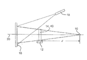
光源10、試験サンプル14及び投影スクリーン16は測定装置の光軸に沿って配置される。光軸20は光源10と、サンプルの中心点を通って延びている。投影スクリーン16は光軸20に対して垂直である。光源10とサンプル14間の距離dは約2m、サンプル14と投影スクリーン16間の距離は約1mである。
【0040】
カメラ18は光軸20の幾分側方又は側部に配置され、それによって、投影スクリーン16上の試験サンプル14の陰影が、試験サンプル14又は装置の他の要素がカメラ18の像フィールドを邪魔したり、入りこむことなく受け入れられる。また、測定装置の光軸20とカメラ18の光軸がなす角度を出来るだけ小さくし、相対変形を少なく保つようにする。また、カメラ18に対して投影スクリーン16を任意に傾けるようにしても良い。
【0041】
ガラス質又は結晶質の光学材料から成る、通常円板状のサンプル14をサンプルホルダー12が受け止めている。サンプル14はサンプルホルダー12に、測定装置の光軸20が貫通するサンプル14の面がこの光軸に対して垂直になるように、把持されている。サンプル14の光学的中心点は、常に測定装置の光軸20上にあるようにしてある。サンプル14は、光軸20と直交する垂直傾斜軸の周りに約±50°の傾動が可能としてある。更に、サンプル14はその中心を中心として、光軸20と交差する回転軸の周りに少なくとも90°の回転が可能としてある。
【0042】
光軸20が貫通する試験サンプル14の両面は互いに平行であり、光学素子に慣用の仕方で研磨されている。
【0043】
合成シュリーレン板40のパターンは、シャドウ法で得られた試験サンプル14のシュリーレン影像を既知の位相ずれと既知の幅のシュリーレンと比較するためのものである。
【0044】
試験サンプル14又は合成シュリーレン板40のシュリーレンの陰影は、測定装置内で投影スクリーン16上に投影される。サンプルホルダー12にあるサンプル14は、光力の高い点光源10により所定の光コーンで照射される。投影スクリーン16上の照射強度も同様に、好ましくは少なくとも100ルックスである。光コーンは、ひろがり光ビームとして形成されるのが好ましい。UV遮断フィルタ等の追加の任意光学素子を、光源又は場合により実像の直近傍に限る光路に設けることが出来る。
【0045】
光ビームがサンプルを通ると、シュリーレンによる回折光と光源からの一次光コーンとの位相依存重ね合わせとして陰影影像が発生する。このシュリーレン情報は主として、位相内に第一次近似として含まれているので、それにより微小成分のみが振幅変調され、この部分のみがその後の処理なく強度差として検出される。
【0046】
さて、この極めてコントラストの乏しい振幅信号を、出来るだけ無干渉の、高いS/N比で受像する。更に、光学素子を用いて空中で生成される影像ではなく、投影スクリーン16上に生成される実際の影像を検出することは有利である。投影スクリーン16は光指向素子無しに拡散光を散乱するものでなければならず、検出可能な表面構造が有ってはならない。スクリーン上の拡散反射率は、場所によって変わってはならない。
【0047】
スクリーン影像のコントラストは1%未満であるから、ディジタルカメラ18でのコントラストを増幅し、次いで影像をディジタル形式でデータに保存するためディジタル化が行われるようにする必要がある。更に、この目的のためには、ピクセルカウントが出来るだけ高く(例えば1300×1030ピクセル)、また12ビットディジタル化手段を備えたCCDカメラを用いなければならない。
【0048】
カメラで受像する生データは、カメラ18の局所感度差及び場合により投影スクリーン16上の局部変化を除くように処理されねばならない。また、コントラストの高いシュリーレン表示を得るように処理されなければならないが、これは市販のCCDカメラと共にコントラスト及び強度制御又は検出機能をもつ影像処理ソフトウェアによって得られるものと同様な通常のコンピュータプログラムを用いて出来る。
【0049】
生データの処理はソフトウェアにより簡単、且つ容易に行われるものの、これは用意されなければならない。シュリーレン影像検出はディスク・光学素子のすりきず、けば、表面欠陥及び洗浄不良間を区別出来なければならない。また、ノイズより小さいシュリーレンも適切なコントラストで検出可能である。影像検出は主に目と脳の協働の真似であるから、シュリーレンは人間による検出の場合と同様、コントラストの変動によって区別されることになる。従って、シュリーレンフィルタは平均的、暗い又は明るい光強度の点群又は領域群を線に沿って検索していく。図3に示されているように、シュリーレンは明るい中心部と暗い縁部の有る細長い形状によって特徴付けられる。これに対して、シュリーレンの無い領域は平均的明るさによって特徴付けられる。シュリーレンを含む一領域の断面は従って、平均的明るさ(無シュリーレン域)から暗いシュリーレン縁部へ、次いで明るいシュリーレン中心、そして再び、第1のシュリーレン縁部とは反対側にシュリーレン縁部へ、最後に平均的明るさへの移行を示している。長手方向に互いに続く複数隣接部がこの種の明るさ特性を有するとき、シュリーレンが検出されたと結論することが出来る。この種のソフトウェアは、複数の既知のパラメタを用い、既知の方法で最適化を行うことが出来る。このことは、平均的−暗い−明るい−暗い−平均的と変わる明るさ特性間のコントラスト閾値が設定されなければならず、明るさ特性の対称性が確定されなければならないことを意味する。更に、シュリーレン構造の存在を確定する同一特性を有する隣接部の数が決定されなければならない。同様に、これ等形式のシュリーレンの幅は同じでない。図3に、典型的なシュリーレン影像が示されている。
【0050】
試験しようとする光学材料の試験サンプル14からのシュリーレンの陰影影像を既知の幅と位相ずれのシュリーレンで較正及び相関させるために受像条件を制御するため、人工シュリーレン板40がサンプルホルダー12に取り付けられる。投影スクリーン16へのシュリーレンパターンの影像が、カメラ18に受像される。次いで、位相ずれに対するシュリーレンコントラストの依存性が、カメラを同一影像尺度、オフセット及び倍率又は増幅率として測定される。
【0051】
図2に、上記測定装置を用いて得られた、人工シュリーレン板40の陰影影像を示す。図2にはまた、位相ずれとシュリーレン幅の数値が含まれている。この合成シュリーレン板40に付いて測定された影像コントラストを、位相ずれとシュリーレン幅の関数として表示し、試験しようとする材料から成る試験サンプル14の影像コントラストと比較する。
【0052】
この比較は、カメラ18に電子影像処理装置を連結して行われる。測定影像コントラストのグレースケール値を互いに比較し、この比較から試験サンプル14内シュリーレンの定量的評定が得られる。
【0053】
同一形式の試験サンプル14に対して、人工シュリーレン板40の陰影影像を新たに撮る必要は無い。人工シュリーレン板40の陰影影像は影像処理装置に、既に多かれ少なかれ用意された形式で電子的に保存が可能である。
【0054】
従って、人工シュリーレン板40による較正は、それ以後の比較はコンピュータ又は処理手段で実行が可能であるので、原則として一度限り必要である。即ち、人工シュリーレン板で生成される影像強度又はコントラストはコンピュータ又は処理手段に比較の基準として記憶されるからである。それにも拘わらず、人工シュリーレン板40に対してカメラにより得られた影像のコントラスト値又は強度が変化しているかどうかを調べることが重要なことも折々ある。その理由は、カメラ焦点合わせの変化、カメラレンズのほこりと汚れ、又は工学的欠陥である。同じことが、それでシュリーレンが生成される光源についても云える。光源、レンズ及び他の構成部品の経時変化も、そのような照度強さの変化を惹起することがある。後で行われる測定では、人工シュリーレン板40のみが調整されるようにして、コンピュータ又は処理手段に記憶された基準値が有効であることを保証する。
【0055】
上記の方法及び装置は人工レンズ用材料のみならず、他の光学素子用材料、例えばプリズム、立方体、光ガイド等の材料内のシュリーレンの測定にも適切である。弗化カルシウム、弗化バリウム、弗化ストロンチウム及び弗化ナトリウムの結晶並びに他の結晶、特に大型の結晶の使用が特に好適である。
【0056】
本発明はレンズ、プリズム、光ガイドロッド、光学窓、及び他の光学的構成部品、例えばDUV光リソグラフィー、ステッパ、レーザ、特にエキシマレーザ、ウェーハ、コンピュータチップ並びに集積回路、及び回路とチップをもつ電子デバイスの製造に用いられる材料を試験するために使用できる方法及び装置に係わる。
【0057】
以上、シュリーレン分析方法及び装置に具現されるものとして本発明を例示、記載したが、本発明の精神を如何ようにも逸脱することなく種々の修正及び変更が可能であるから、本発明は示された詳細に限定されるものではない。
従って、以上は本発明の要旨を、他者が現在の知識を適用することにより、本発明の一般的又は特定の側面の本質的特徴を、従来技術の観点から相応に構成する特徴を省略することなく、それを種々の応用に適用出来る程度まで十分に示すものである。
【図面の簡単な説明】
【図1】本発明によるシャドウ方法により試験サンプルのシュリーレンを測定するための装置の概略的断面図である。
【図2】本発明に従って人工シュリーレンをもつ比較サンプルである合成シュリーレン板の陰影影像の平面図である。
【図3】光学結晶での典型的シュリーレンパターンの平面図である。
【符号の説明】
10 点光源
12 サンプルホルダー
14 試験サンプル
16 投影スクリーン
18 ディジタルカメラ
20 測定装置の光軸
40 規格サンプル[0001]
[Industrial application fields]
The present invention relates to a method and apparatus for measuring schlieren in optical materials by the shadow method.
[0002]
[Prior art]
Schlieren, in the usual language, is a bounded region in an optical material that acts optically due to local changes in the refractive index, most appearing as images or images as lines, strips and bands. is there. Nearly all optical materials have refractive indices that are not exactly constant throughout, but differ within a certain range. Schlieren is defined as optical inhomogeneity with a small structure width and high refractive index gradient.
[0003]
Various different methods are known for detecting schlieren in optical materials. Virtually all of these methods are based on detecting changes in the light wavefront (head) after passing through the sample to be tested and analyzed. Interferometry, teffler and shadow methods are the most widely used methods.
[0004]
Wavefront changes are detected directly by interferometry and tefler methods, but surface defects on the test sample, such as surfaces that are not perfectly flat, directly affect the measurement. These measurements require a great deal of effort and expense because they require a high degree of uniformity in the surface of the test sample.
[0005]
Usually commercially available interferometers are not readily available for schlieren measurements, and if you want to measure schlieren with an interferometer, you must make an interferometer for that purpose. That is, it is necessary that the interferometer has sufficient spatial resolution so that a fine schlieren structure having a size in the micron range can be detected.
[0006]
In order to detect schlieren, it is better to use the shadow method. This is because the sensitivity is relatively high and the surface quality of the sample is similar to that of a typical optical material.
[0007]
In the shadow method, an optical material is placed between the light source and the observer, and the shadow method schlieren is set by moving and tilting the sample (MIL-G-174A and similar standards), or the sample is irradiated with light. The schlieren contained in the sample is projected as a shade (DDR professional standard TGL21790, similar ISO standard widely enforced).
[0008]
DIN3140 and Part 3 are also related to schlieren, but their significance is limited.
[0009]
Since Schlieren is a spatial form, both Standard TGL21790 and Standard DIN3140 attempt to characterize the extent of Schlieren with an effective Schlieren surface. The known method has the disadvantage that it strongly depends on the subjective rating of the observer. In the standard TGL21790, deterministic schlieren comparisons are obtained from visibility threshold measurements. However, in the known method, since the comparison between the schlieren image (image) and the test pattern is performed by eyes, it depends to some extent on the subjective observation ability of the observer.
[0010]
In the conventional method, the shadow image of each test sample is copied (copied) on paper, the width and intensity of each shadow line are subjectively evaluated, and the evaluation or analysis is recorded on the sketch.
[0011]
Furthermore, the above standards relate only to glass or glass-like materials. However, crystalline materials are increasingly being used for optical components, particularly those with wavelengths outside the visible range, i.e., well below about 400 nm and well above about 800 nm. Thus, for UV applications such as UV lithography, or for lenses and windows for irradiation and imaging devices, for alkali metal and alkaline earth metal fluoride (especially CaF 2 , BaF 2 , SrF 2 ) single crystal materials Demand is increasing. Crystal materials are the basis for many optical elements in the IR spectral range.
[0012]
Glass and crystal differ depending on their disordered structure and regular structure. The cause of schlieren in the crystal and the cause of schlieren in the glass may be completely different. In particular, the activity of schlieren in crystals depends extremely strongly on the position and orientation of inhomogeneity (for example, grain boundaries) that generate schlieren. In a crystal, a band-like structure (for example, displacement, small-angle grain boundary) having a large width but a small thickness may generate schlieren. The method developed for glass is not suitable for analyzing schlieren substrates of the above type with the required accuracy.
[0013]
Also, test or comparative schlieren samples for glass cannot be used for crystals because the mechanisms for generating schlieren in crystals are quite different. Coatings in known comparative schlieren test plates developed for optical glass simulate phase discontinuities with different thicknesses and widths. However, such a two-dimensional schlieren test plate is not suitable for representing the action of schlieren in crystals.
[0014]
In particular, during the tests of the present invention, the sign of phase deviation or deviation is the opposite of that for glass for single crystal materials. However, the schlieren test and comparison plates known so far are usually made from insensitive materials such as quartz or quartz glass. Different structures are provided on this plate using a thin film or light mask. Usually, for example, a cavity or opening having a width of 0.2 mm and a length of 1 cm is provided in a 10 nm film, and a phase shift is generated when the wavefront passes. In principle, a phase shift can be generated by applying a convex portion instead of a cavity or an opening so that the direction of the shift is changed. However, the subjective intensity and width of the lines in the shaded image measured using the comparative and test samples, the test sample made from a crystalline material because the change in refractive index causes a change in the light wavefront There is no reliable significance for.
[0015]
It has been found within the scope of the present invention that most of the results obtained by comparing the crystalline material with known Schlieren test plates by the shadow method are unusable and unreliable. In fact, no appropriate conclusions have been presented regarding the quality of crystalline optical elements.
[0016]
[Problems to be solved by the invention]
An object of the present invention is to provide an objective schlieren analysis / measurement method and apparatus based on the shadow method, which is suitable not only for optical glass materials but also for crystalline materials.
Another object of the present invention is to provide a method independent of the subjective schlieren analysis / measurement method using the shadow method currently used.
It is also an object of the present invention to provide an apparatus for performing these methods for schlieren analysis and measurement.
[0017]
[Means for Solving the Problems]
The schlieren analysis and measurement method according to the present invention comprises the following steps:
a) irradiating the test sample with light from the light source;
b) generating a shadow image of the test sample on the projection screen;
c) receiving a shadow image of the test sample projected on the projection screen in an electronic receiver, preferably a digital camera;
d) processing the shadow image received by the electronic image receiving device to measure the Schlieren image (image) contrast;
e) Compare the schlieren image contrast measured in the shadow image of the test sample with the schlieren image contrast of the shadow image of the schlieren pattern of the comparative sample, and evaluate the schlieren of the test sample by this comparison.
[0018]
An apparatus for carrying out the method of the present invention comprises a light source for irradiating a test sample, a sample holder for holding a test sample or a comparison sample, a projection screen, and an electronic video receiver, preferably a digital camera.
[0019]
According to the present invention, the shadow formed by schlieren in the sample is acquired and received by the digital camera, and the contrast of the shadow image (shadow image) is determined by video processing. In the shadow method, it is not possible to directly measure the wavefront delay in the material by changing the light wavelength, so the image obtained by the shadow method can be standardized or structured using a known wavefront delay structure. Calibrate. The schlieren of any sample (comparative sample) is measured by interferometry and correlated with the shadow image or contrast of each schlieren. This correlation is also referred to as primary or original (original) calibration. As a comparative sample, it is desirable to use a crystal piece made of the same material as the optical material of the test sample to be evaluated. Particularly preferred as test samples are those with different schlieren patterns, such as strong or weak schlieren.
[0020]
In other words, it is possible to determine the optical properties of a material, especially a crystalline material, by using the shadow method in practice and performing a calibration to relate the value obtained by the shadow method to the value obtained by the interferometry. .
[0021]
Therefore, the present invention is basically based on the shadow method, but this is combined with a novel comparison method, that is, a comparison method in which the comparison is not performed visually but by electronic image formation.
[0022]
The schlieren pattern received by the camera is digitally processed and the resulting digital image is compared with the schlieren pattern from the original or primary calibration so that the average wavefront deviation is accurately determined with interferometric accuracy. A detection limit of about 550 nm and a phase shift of less than 5 nm is possible. A digital CCD camera can be used as the electronic image processing apparatus of the present invention. However, the required resolution of the image processing camera depends on each material under test and also on the interferometer. Preferably at least 10 microns / pixel, more preferably at least 15 microns / pixel. For example, 20 microns / pixel has been achieved with calcium fluoride.
[0023]
Samples evaluated by the method and apparatus according to the present invention do not require expensive interferometry measurements. The required calibration by the interferometer of the measuring device is only performed once on a shadow image of a sample of the same material. In this calibration, the calibration value obtained thereby is later compared with the value obtained from the test sample. This is because it is proved that the contrast is always the same if the product of the square of the phase shift and the phase width is the same. The calibration values of the original or primary calibration are preferably stored in the processor or processing means so that calibration data (virtual schlieren plates) that can be retrieved at any time are generated.
[0024]
According to the present invention, the original or primary calibration data is still compared with the shadow cast by a conventional synthetic schlieren plate. Since the contrast, or the contrast obtained with the camera, also depends on the screen on which the shadow is generated and the focus and brightness of the light source, it is easy to test whether calibration is always valid even with a synthetic schlieren plate. I can do it.
[0025]
By electronically processing the test sample shadow image and the comparison sample image, it is possible to quantitatively classify the generated schlieren without depending on the subjective judgment of the observer. The measurement of schlieren by such shading is quick, simple and economical.
[0026]
Embodiment
The measurement method by the shadow method described below detects and evaluates schlieren in the glassy and crystalline optical materials in the direction of the RMS wavefront deformation Wrms with interferometric accuracy. Wrms 2 is obtained for sample classification, which is proportional to the product of the square of the phase shift and the width and length of each individual schlieren, divided by the total surface area of the sample. Wrms 2 = (k / F) ΣLBw 2 (1)
Where k: proportional coefficient F: total area of sample W: phase shift L: schlieren length B (in the material) B: schlieren width (in the material).
[0027]
The image (image) contrast provided by a given optical system is related to the RMS wavefront deformation at a given wavelength λ by the relationship:
ΔT = ((4π / λ) Wrms) 2 (2)
[0028]
Schlieren needs to be detected and evaluated with a phase shift of, for example, 5 nm or less at a wavelength of 550 nm, particularly in crystals used in the UV spectral range.
[0029]
Measurement work is planned to be suitable for continuous testing of the manufacturing process. In particular, optical materials can be tested in the manufacturing process without additional finishing. For detection and evaluation of schlieren, a sample of the optical material to be tested may be rotated and tilted.
[0030]
Next, the schlieren detection rating device will be described.
[0031]
The apparatus essentially comprises the optical device shown in FIG. 1, which comprises a point
[0032]
Since the phase shift in the comparative sample 40 also depends on the material, a comparative sample consisting of the same as the test sample 14 is used. Alternatively, it is always possible to calibrate these comparison samples with comparison samples made of the same optical material as the sample being tested, using other comparison samples made of different materials. The schlieren pattern pattern of the calibrated schlieren plate calibrated in this way can be correlated with the schlieren pattern of plates or samples of other materials such as calcium fluoride or sodium fluoride at any time.
[0033]
As the schlieren plate, quartz or quartz glass is preferably used because it is a material that is not easily damaged.
[0034]
During calibration, the shadow formation on the composite schlieren plate, and hence the contrast, is measured, and after or before, the phase shift and phase width of each shadow image of the test sample is measured using interferometry. Since the square of the phase shift multiplied by the schlieren width is proportional to the contrast, the contrast can thus be correlated to the product of the phase shift and the width. The required interferometer spatial resolution depends on the schlieren width to be measured. For example, a spatial resolution of 0.01 mm / pixel has been found to be sufficient for a Schlieren width of 0.1 mm. It is desirable that the spatial resolution per pixel is at least 5%, preferably at least 8%, particularly preferably 10% of the schlieren width per pixel. In many cases, interferometers with a spatial resolution of 200 nm / pixel or less are used in the method.
[0035]
The rms value to be measured can then be determined by the sum of the product of each squared square multiplied by the width and length of the individual schlieren divided by the total surface area of the sample.
[0036]
Of course, in this method, the phase shift or the schlieren width cannot be determined independently from the shadow image. But identification of the optical material is not necessary. The correlation between contrast and rms value is slightly dependent on schlieren width and is therefore sufficient for deterministic schlieren classification.
[0037]
Schlieren should be measured at the same angle of incidence as used for the material application being measured. This is also true for the exit angle.
[0038]
The visibility of schlieren in the test sample depends on the angle of incidence. The shadow image disappears or changes significantly only by changing the incident angle of light by 1 to 2 °.
[0039]
The
[0040]
The
[0041]
The
[0042]
Both surfaces of the test sample 14 through which the
[0043]
The pattern of the synthetic schlieren plate 40 is for comparing the schlieren image of the test sample 14 obtained by the shadow method with a known phase shift and a known width of the schlieren.
[0044]
The schlieren shadow of the test sample 14 or the synthetic schlieren plate 40 is projected onto the
[0045]
When the light beam passes through the sample, a shadow image is generated as a phase-dependent superposition of the diffracted light by Schlieren and the primary light cone from the light source. Since this schlieren information is mainly included in the phase as a first approximation, only a minute component is amplitude-modulated by this, and only this portion is detected as an intensity difference without further processing.
[0046]
Now, the amplitude signal with extremely low contrast is received with a high S / N ratio with as little interference as possible. Furthermore, it is advantageous to detect the actual image generated on the
[0047]
Since the contrast of the screen image is less than 1%, it is necessary to amplify the contrast at the
[0048]
The raw data received by the camera must be processed to eliminate the local sensitivity difference of the
[0049]
Although raw data processing is simple and easy to do with software, it must be prepared. Schlieren image detection must be able to distinguish between scratches on the disk and optical elements, and thus surface defects and poor cleaning. Further, schlieren smaller than noise can be detected with appropriate contrast. Since image detection is primarily an imitation of eye-brain collaboration, Schlieren will be distinguished by contrast variations, similar to human detection. Thus, the Schlieren filter searches along the line for points or regions of average, dark or bright light intensity. As shown in FIG. 3, schlieren is characterized by an elongated shape with a bright center and dark edges. In contrast, areas without schlieren are characterized by average brightness. The cross section of one area containing schlieren is therefore from average brightness (no schlieren area) to a dark schlieren edge, then to a bright schlieren center, and again to the schlieren edge opposite the first schlieren edge, Finally, the transition to average brightness is shown. It can be concluded that schlieren has been detected when a plurality of adjoining portions that are adjacent to each other in the longitudinal direction have this kind of brightness characteristic. This kind of software can be optimized by a known method using a plurality of known parameters. This means that a contrast threshold between the average-dark-bright-dark-average and changing brightness characteristics must be set and the symmetry of the brightness characteristics must be established. Furthermore, the number of neighbors with the same properties that determine the existence of a schlieren structure must be determined. Similarly, the widths of these types of schlieren are not the same. A typical schlieren image is shown in FIG.
[0050]
An artificial schlieren plate 40 is attached to the
[0051]
FIG. 2 shows a shadow image of the artificial schlieren plate 40 obtained by using the measurement apparatus. FIG. 2 also includes numerical values for phase shift and schlieren width. The image contrast measured for this composite schlieren plate 40 is displayed as a function of phase shift and schlieren width and compared with the image contrast of the test sample 14 made of the material to be tested.
[0052]
This comparison is performed by connecting an electronic image processing apparatus to the
[0053]
There is no need to take a new shadow image of the artificial schlieren plate 40 for the test sample 14 of the same type. The shadow image of the artificial schlieren plate 40 can be stored electronically in a format already more or less prepared in the image processing apparatus.
[0054]
Therefore, the calibration by the artificial schlieren plate 40 is necessary only once in principle because the subsequent comparison can be performed by a computer or processing means. That is, the image intensity or contrast generated by the artificial schlieren plate is stored as a reference for comparison in the computer or processing means. Nevertheless, it is sometimes important to examine whether the contrast value or intensity of the image obtained by the camera with respect to the artificial schlieren plate 40 has changed. The reason is camera focus change, camera lens dust and dirt, or engineering defects. The same is true for light sources from which schlieren is generated. Changes over time in the light source, lens and other components may also cause such changes in illuminance intensity. In later measurements, only the artificial schlieren plate 40 is adjusted to ensure that the reference value stored in the computer or processing means is valid.
[0055]
The above method and apparatus are suitable not only for measuring materials for artificial lenses but also for measuring schlieren in other materials for optical elements such as prisms, cubes, light guides and the like. The use of crystals of calcium fluoride, barium fluoride, strontium fluoride and sodium fluoride as well as other crystals, particularly large crystals, is particularly preferred.
[0056]
The present invention relates to lenses, prisms, light guide rods, optical windows, and other optical components such as DUV photolithography, steppers, lasers, especially excimer lasers, wafers, computer chips and integrated circuits, and electronics with circuits and chips. The present invention relates to methods and apparatus that can be used to test materials used in the manufacture of devices.
[0057]
While the present invention has been illustrated and described as embodied in a schlieren analysis method and apparatus, various modifications and changes can be made without departing from the spirit of the present invention in any way. It is not intended to be limited to the details provided.
Accordingly, the foregoing omits features that constitute the essential features of the general or specific aspects of the present invention from the point of view of the prior art by applying the present knowledge to others and applying the current knowledge to others. It is sufficient to show that it can be applied to various applications.
[Brief description of the drawings]
1 is a schematic cross-sectional view of an apparatus for measuring schlieren of a test sample by a shadow method according to the present invention.
FIG. 2 is a plan view of a shadow image of a synthetic schlieren plate which is a comparative sample having an artificial schlieren according to the present invention.
FIG. 3 is a plan view of a typical schlieren pattern in an optical crystal.
[Explanation of symbols]
10
Claims (16)
a)試験サンプルに光源からの光を照射し、
b)投影スクリーン上に試験サンプルの陰影影像(シャドウイメージ)を生成し、
c)投影スクリーン上に投影された試験サンプルの陰影影像を電子受像装置に受像し、
d)電子受像装置に受像した陰影影像を処理してシュリーレン影像(イメージ)コントラストを測定し、
e)試験サンプルの陰影影像にて測定された上記シュリーレン影像コントラストを比較サンプルのシュリーレンパターンの陰影影像のシュリーレン影像コントラストと比較し、この比較によって試験サンプルのシュリーレンを評定する。Schlieren analysis method comprising the following steps:
a) irradiating the test sample with light from the light source;
b) generating a shadow image of the test sample on the projection screen;
c) A shadow image of the test sample projected on the projection screen is received by the electronic receiver,
d) processing the shadow image received by the electronic image receiving device to measure the Schlieren image (image) contrast;
e) Compare the schlieren image contrast measured in the shadow image of the test sample with the schlieren image contrast of the shadow image of the schlieren pattern of the comparative sample, and evaluate the schlieren of the test sample by this comparison.
サンプルホルダーと光源とを含み、該光源からの光を試験サンプルに照射する手段と、
投影スクリーンを含み、該投影スクリーン上に試験サンプルの陰影影像を生成する手段と、
投影スクリーンに投影された試験サンプルの陰影影像を電子受像装置で受像する手段と、
上記陰影影像を受像する手段と電子的に結合され、電子受像装置で受像した陰影影像を処理してシュリーレン影像コントラストを測定する手段と、
試験サンプルの陰影影像で測定された測定シュリーレン影像コントラストを、比較サンプルのシュリーレンパターンの陰影影像のシュリーレン影像コントラストと比較し、この比較によって試験サンプルのシュリーレン影像コントラストを評定する手段。A Schlieren analysis device comprising:
Means for irradiating the test sample with light from the light source, including a sample holder and a light source;
Means for generating a shadow image of the test sample on the projection screen, the projection screen comprising:
Means for receiving a shadow image of the test sample projected on the projection screen with an electronic receiver;
Means for electronically coupled with the means for receiving the shadow image, processing the shadow image received by the electronic image receiving device and measuring the Schlieren image contrast;
Means for comparing the measured schlieren image contrast measured in the shadow image of the test sample with the schlieren image contrast of the shadow image of the schlieren pattern of the comparative sample, and for evaluating the schlieren image contrast of the test sample by this comparison.
a)試験サンプルに光源からの光を照射し、
b)投陰影スクリーン上に試験サンプルの陰影影像を生成し、
c)投影スクリーン上に投影された試験サンプルの陰影影像を電子受像装置に受像し、
d)電子受像装置に受像した陰影影像を処理してシュリーレン影像コントラストを測定し、
e)試験サンプルの陰影影像にて測定された上記測定シュリーレン影像コントラストを比較サンプルのシュリーレンパターンの陰影影像のシュリーレン影像コントラストと比較し、この比較によって試験サンプルのシュリーレンを評定する。Optical material measurements for manufacturing lenses, prisms, photoconductive rods, optical windows and optical components for DUV photolithography, lasers including steppers, excimer lasers, wafers, computer chips, integrated circuits, and electronic devices including integrated circuits A method comprising a schlieren analysis method of an optical material, the schlieren analysis method comprising the following steps:
a) irradiating the test sample with light from the light source;
b) generating a shadow image of the test sample on the shadow screen;
c) A shadow image of the test sample projected on the projection screen is received by the electronic receiver,
d) processing the shadow image received by the electronic image receiver to measure the Schlieren image contrast;
e) The measured schlieren image contrast measured on the shadow image of the test sample is compared with the schlieren image contrast of the shadow image of the schlieren pattern of the comparative sample, and the schlieren of the test sample is evaluated by this comparison.
Applications Claiming Priority (2)
| Application Number | Priority Date | Filing Date | Title |
|---|---|---|---|
| DE10111450.8 | 2001-03-09 | ||
| DE10111450A DE10111450B4 (en) | 2001-03-09 | 2001-03-09 | Method and apparatus for evaluating streaks |
Publications (3)
| Publication Number | Publication Date |
|---|---|
| JP2003021596A JP2003021596A (en) | 2003-01-24 |
| JP3653591B2 true JP3653591B2 (en) | 2005-05-25 |
| JP2003021596A5 JP2003021596A5 (en) | 2005-07-14 |
Family
ID=7676915
Family Applications (1)
| Application Number | Title | Priority Date | Filing Date |
|---|---|---|---|
| JP2002108578A Expired - Fee Related JP3653591B2 (en) | 2001-03-09 | 2002-03-07 | Schlieren analysis method and apparatus |
Country Status (5)
| Country | Link |
|---|---|
| US (1) | US6891980B2 (en) |
| EP (1) | EP1239278B9 (en) |
| JP (1) | JP3653591B2 (en) |
| AT (1) | ATE303592T1 (en) |
| DE (2) | DE10111450B4 (en) |
Families Citing this family (16)
| Publication number | Priority date | Publication date | Assignee | Title |
|---|---|---|---|---|
| DE10227345A1 (en) | 2002-06-19 | 2004-01-15 | Schott Glas | Method for the determination of local structures in optical crystals |
| GB0306259D0 (en) * | 2003-03-19 | 2003-04-23 | Pilkington Plc | Method to determine the optical quality of a glazing |
| GB0307345D0 (en) * | 2003-03-29 | 2003-05-07 | Pilkington Plc | Glazing inspection |
| DE102007060063B4 (en) * | 2007-12-11 | 2011-07-07 | VisuMotion GmbH, 07745 | Method for checking irregularities in optical filters |
| GB0914651D0 (en) * | 2009-08-21 | 2009-09-30 | Pilkington Automotive D Gmbh | Heatable glazing inspection |
| DE102009041544A1 (en) * | 2009-09-15 | 2011-03-24 | GFE Gesellschaft für Fertigungstechnik u. Entwicklung Schmalkalden e.V. | Device for examining and evaluating windscreen wiper blade, has two or multiple cameras for determination of shade throw illustrated on projection surface |
| DE102012002174B4 (en) | 2012-02-07 | 2014-05-15 | Schott Ag | Apparatus and method for detecting defects within the volume of a transparent pane and using the apparatus |
| CN102928429B (en) * | 2012-11-08 | 2015-04-22 | 中国建材检验认证集团秦皇岛有限公司 | Device for observing weathering of glass and test method for observing weathering of glass by using device |
| DE102013105693A1 (en) | 2013-06-03 | 2013-10-31 | Viprotron Gmbh | Method for optical error inspection of object, involves projecting light beams from illumination surface on projection surface arranged behind object, and detecting shadow impact generated on projection surface with optical detection unit |
| TW201506406A (en) | 2013-08-13 | 2015-02-16 | Univ Nat Taiwan | Analysis method for fluid and analysis system for fluid |
| CN103743761B (en) * | 2013-12-31 | 2017-06-23 | 江苏大学附属医院 | A kind of eyeglass watermark defect image detection device |
| US10373343B1 (en) * | 2015-05-28 | 2019-08-06 | Certainteed Corporation | System for visualization of a building material |
| US11195324B1 (en) | 2018-08-14 | 2021-12-07 | Certainteed Llc | Systems and methods for visualization of building structures |
| CN111127559B (en) * | 2019-12-26 | 2023-06-16 | 深圳市瑞立视多媒体科技有限公司 | Calibration rod detection method, device, equipment and storage medium in optical dynamic capture system |
| CN112748626B (en) * | 2021-02-02 | 2021-11-26 | 哈尔滨工业大学 | Visualization device for shock wave high-speed digital shadow imaging |
| CN114923866B (en) * | 2022-04-11 | 2023-03-24 | 哈尔滨工程大学 | Gas-liquid two-phase flow same-field testing system and processing method based on schlieren and MIE method |
Family Cites Families (8)
| Publication number | Priority date | Publication date | Assignee | Title |
|---|---|---|---|---|
| US4121247A (en) * | 1977-04-21 | 1978-10-17 | Eastman Kodak Company | Population and profile display of transparent bodies in a transparent mass |
| DE69023217T2 (en) * | 1989-08-03 | 1996-07-18 | Japan Broadcasting Corp | PROJECTION VISOR WITH OPTICAL WRITING. |
| US5291102A (en) * | 1990-10-12 | 1994-03-01 | Washburn Clayton A | Dynamic color separation display |
| JPH05181166A (en) * | 1992-01-06 | 1993-07-23 | Canon Inc | Projection type display device |
| US5577733A (en) * | 1994-04-08 | 1996-11-26 | Downing; Dennis L. | Targeting system |
| FR2720831B3 (en) * | 1994-06-02 | 1996-07-12 | Saint Gobain Vitrage | Method for measuring the optical quality of a glazing. |
| JP3404134B2 (en) * | 1994-06-21 | 2003-05-06 | 株式会社ニュークリエイション | Inspection device |
| DE69620896T2 (en) * | 1995-09-12 | 2002-10-10 | Corning Inc | CALLED DETECTION METHOD |
-
2001
- 2001-03-09 DE DE10111450A patent/DE10111450B4/en not_active Expired - Fee Related
-
2002
- 2002-03-05 US US10/090,975 patent/US6891980B2/en not_active Expired - Fee Related
- 2002-03-07 JP JP2002108578A patent/JP3653591B2/en not_active Expired - Fee Related
- 2002-03-08 AT AT02005456T patent/ATE303592T1/en not_active IP Right Cessation
- 2002-03-08 EP EP02005456A patent/EP1239278B9/en not_active Expired - Lifetime
- 2002-03-08 DE DE50204051T patent/DE50204051D1/en not_active Expired - Lifetime
Also Published As
| Publication number | Publication date |
|---|---|
| EP1239278B1 (en) | 2005-08-31 |
| DE50204051D1 (en) | 2005-10-06 |
| ATE303592T1 (en) | 2005-09-15 |
| EP1239278A8 (en) | 2002-12-18 |
| EP1239278A1 (en) | 2002-09-11 |
| US6891980B2 (en) | 2005-05-10 |
| JP2003021596A (en) | 2003-01-24 |
| EP1239278B9 (en) | 2006-01-11 |
| DE10111450A1 (en) | 2002-09-19 |
| DE10111450B4 (en) | 2005-02-10 |
| US20020154814A1 (en) | 2002-10-24 |
Similar Documents
| Publication | Publication Date | Title |
|---|---|---|
| JP3653591B2 (en) | Schlieren analysis method and apparatus | |
| JP3995579B2 (en) | Film thickness measuring device and reflectance measuring device | |
| KR100872621B1 (en) | Method for quantitatively evaluating scintillation | |
| US7312866B2 (en) | Methods and systems for substrate surface evaluation | |
| JP5472096B2 (en) | Imaging optical inspection apparatus and method for inspecting planar reflective surface of sample | |
| US6486951B2 (en) | Method of evaluating an anisotropic thin film and an evaluating apparatus | |
| JP2005292146A (en) | Method and apparatus for quantitatively measuring optical quality of transparent material | |
| KR100334222B1 (en) | Method of and apparatus for inspecting surface irregularities of transparent plate | |
| US20090015833A1 (en) | Device and method for improving the measurement accuracy in an optical cd measurement system | |
| JP3417494B2 (en) | Method and apparatus for inspecting surface undulation of glass substrate | |
| JPH08247954A (en) | Measuring method of optical distortion | |
| JP4260555B2 (en) | Method for determining local structure in optical crystal | |
| JP3770294B2 (en) | Film evaluation method and film evaluation apparatus | |
| JPH10111237A (en) | Manufacture of liquid crystal display device, method and apparatus for optical inspection | |
| TW468151B (en) | Method and device for optical detection of local deformations, especially bubbles, in an optical data carrier | |
| JP3039211B2 (en) | Painted surface property measuring device | |
| JPS61217708A (en) | Method and apparatus for measuring surface properties | |
| JPH05256773A (en) | Device for inspecting properties of coating surface | |
| JP2982471B2 (en) | Painted surface inspection equipment | |
| JPH10293103A (en) | Method and equipment for optical measurement and optical measuring equipment for patterned substrate | |
| JP2797819B2 (en) | Painted surface inspection equipment | |
| JPH0580496A (en) | Foreign matter inspecting device | |
| JPH01313743A (en) | Method for inspecting colored periodic pattern | |
| Dubbeldam | Visualizing the topography of coating surfaces | |
| JPH0313851A (en) | Sensitivity correcting method for image sensor element |
Legal Events
| Date | Code | Title | Description |
|---|---|---|---|
| A521 | Request for written amendment filed |
Free format text: JAPANESE INTERMEDIATE CODE: A523 Effective date: 20041124 |
|
| TRDD | Decision of grant or rejection written | ||
| A01 | Written decision to grant a patent or to grant a registration (utility model) |
Free format text: JAPANESE INTERMEDIATE CODE: A01 Effective date: 20050126 |
|
| A61 | First payment of annual fees (during grant procedure) |
Free format text: JAPANESE INTERMEDIATE CODE: A61 Effective date: 20050214 |
|
| R150 | Certificate of patent or registration of utility model |
Free format text: JAPANESE INTERMEDIATE CODE: R150 |
|
| S111 | Request for change of ownership or part of ownership |
Free format text: JAPANESE INTERMEDIATE CODE: R313117 |
|
| S531 | Written request for registration of change of domicile |
Free format text: JAPANESE INTERMEDIATE CODE: R313531 |
|
| R360 | Written notification for declining of transfer of rights |
Free format text: JAPANESE INTERMEDIATE CODE: R360 |
|
| R371 | Transfer withdrawn |
Free format text: JAPANESE INTERMEDIATE CODE: R371 |
|
| S111 | Request for change of ownership or part of ownership |
Free format text: JAPANESE INTERMEDIATE CODE: R313117 |
|
| S531 | Written request for registration of change of domicile |
Free format text: JAPANESE INTERMEDIATE CODE: R313531 |
|
| R350 | Written notification of registration of transfer |
Free format text: JAPANESE INTERMEDIATE CODE: R350 |
|
| FPAY | Renewal fee payment (event date is renewal date of database) |
Free format text: PAYMENT UNTIL: 20080311 Year of fee payment: 3 |
|
| FPAY | Renewal fee payment (event date is renewal date of database) |
Free format text: PAYMENT UNTIL: 20090311 Year of fee payment: 4 |
|
| FPAY | Renewal fee payment (event date is renewal date of database) |
Free format text: PAYMENT UNTIL: 20090311 Year of fee payment: 4 |
|
| FPAY | Renewal fee payment (event date is renewal date of database) |
Free format text: PAYMENT UNTIL: 20100311 Year of fee payment: 5 |
|
| FPAY | Renewal fee payment (event date is renewal date of database) |
Free format text: PAYMENT UNTIL: 20110311 Year of fee payment: 6 |
|
| FPAY | Renewal fee payment (event date is renewal date of database) |
Free format text: PAYMENT UNTIL: 20110311 Year of fee payment: 6 |
|
| S111 | Request for change of ownership or part of ownership |
Free format text: JAPANESE INTERMEDIATE CODE: R313117 |
|
| FPAY | Renewal fee payment (event date is renewal date of database) |
Free format text: PAYMENT UNTIL: 20110311 Year of fee payment: 6 |
|
| R350 | Written notification of registration of transfer |
Free format text: JAPANESE INTERMEDIATE CODE: R350 |
|
| LAPS | Cancellation because of no payment of annual fees |