JP3639942B2 - Electric power steering device - Google Patents
Electric power steering device Download PDFInfo
- Publication number
- JP3639942B2 JP3639942B2 JP23753897A JP23753897A JP3639942B2 JP 3639942 B2 JP3639942 B2 JP 3639942B2 JP 23753897 A JP23753897 A JP 23753897A JP 23753897 A JP23753897 A JP 23753897A JP 3639942 B2 JP3639942 B2 JP 3639942B2
- Authority
- JP
- Japan
- Prior art keywords
- value
- torque sensor
- output
- electric power
- power steering
- Prior art date
- Legal status (The legal status is an assumption and is not a legal conclusion. Google has not performed a legal analysis and makes no representation as to the accuracy of the status listed.)
- Expired - Fee Related
Links
Images


Classifications
-
- B—PERFORMING OPERATIONS; TRANSPORTING
- B62—LAND VEHICLES FOR TRAVELLING OTHERWISE THAN ON RAILS
- B62D—MOTOR VEHICLES; TRAILERS
- B62D6/00—Arrangements for automatically controlling steering depending on driving conditions sensed and responded to, e.g. control circuits
- B62D6/08—Arrangements for automatically controlling steering depending on driving conditions sensed and responded to, e.g. control circuits responsive only to driver input torque
- B62D6/10—Arrangements for automatically controlling steering depending on driving conditions sensed and responded to, e.g. control circuits responsive only to driver input torque characterised by means for sensing or determining torque
-
- B—PERFORMING OPERATIONS; TRANSPORTING
- B62—LAND VEHICLES FOR TRAVELLING OTHERWISE THAN ON RAILS
- B62D—MOTOR VEHICLES; TRAILERS
- B62D5/00—Power-assisted or power-driven steering
- B62D5/04—Power-assisted or power-driven steering electrical, e.g. using an electric servo-motor connected to, or forming part of, the steering gear
- B62D5/0457—Power-assisted or power-driven steering electrical, e.g. using an electric servo-motor connected to, or forming part of, the steering gear characterised by control features of the drive means as such
- B62D5/0481—Power-assisted or power-driven steering electrical, e.g. using an electric servo-motor connected to, or forming part of, the steering gear characterised by control features of the drive means as such monitoring the steering system, e.g. failures
- B62D5/049—Power-assisted or power-driven steering electrical, e.g. using an electric servo-motor connected to, or forming part of, the steering gear characterised by control features of the drive means as such monitoring the steering system, e.g. failures detecting sensor failures
Landscapes
- Engineering & Computer Science (AREA)
- Chemical & Material Sciences (AREA)
- Combustion & Propulsion (AREA)
- Transportation (AREA)
- Mechanical Engineering (AREA)
- Steering Control In Accordance With Driving Conditions (AREA)
- Power Steering Mechanism (AREA)
Description
【0001】
【発明の属する技術分野】
本発明は、操舵トルクを検出するトルクセンサの出力に基づいて操舵補助する電動パワーステアリング装置の改良に関し、特にトルクセンサの故障検知に関するものである。
【0002】
【従来の技術】
図14は、従来の電動パワーステアリング装置の要部構成例を示すブロック図である。この電動パワーステアリング装置は、操舵軸(図示せず)に設けたトルクセンサ2からの操舵トルク信号が、位相補償部11により位相補償され、アシスト制御部12に与えられる。
また、車速センサ7からの車速信号がアシスト制御部12に与えられる。アシスト制御部12は、位相補償部11からの操舵トルク信号及び車速センサ7からの車速信号に基づいた、アシスト制御(操舵補助制御)のための目標電流値を出力し、減算手段15に与える。
【0003】
減算手段15は、アシスト制御部12からの目標電流値と、モータ電流検出回路6によって検出されたモータ5の駆動電流のフィードバック値との偏差を求め、この偏差をモータ駆動回路16に与える。モータ駆動回路16は、この偏差に基づきモータ電流を決定し、モータ5に与えて回転駆動させる。
【0004】
【発明が解決しようとする課題】
上述したような従来の電動パワーステアリング装置では、トルクセンサ2に過大な入力が加わったときに、その測定の中立点が移動することがあるが、その移動変化が比較的小さいときには、その移動変化を検出できず、トルクセンサ2の測定誤差が大きい状態で放置される問題があった。
【0005】
類似の問題に対する先行技術としては、入力トルクが一定の範囲に入る回数を左右で別々にカウントし、その左右のカウント値の差が、一定レベルを超えたときに、異常が発生したと判断する「電動パワーステアリング装置のフェイルセイフ装置」が特開平1−178080号公報に開示されているが、これは、測定の中立点の移動変化が大きいときのみ、その異常を検知することができるものである。
本発明は、上述したような事情に鑑みてなされたものであり、トルクセンサの測定の中立点の小さな移動変化でも検出できる電動パワーステアリング装置を提供することを目的とする。
【0006】
【課題を解決するための手段】
第1発明に係る電動パワーステアリング装置は、操舵トルクを検出するトルクセンサの出力に基づいて操舵補助する電動パワーステアリング装置において、前記トルクセンサの出力を所定時間積算する積算手段と、該積算手段が積算した積算値の絶対値と所定値とを比較する手段とを備えることを特徴とする。
【0007】
この電動パワーステアリング装置では、積算手段が、トルクセンサの出力を所定時間積算する。比較する手段は、その積算値の絶対値と所定値とを比較する。
トルクセンサの出力の積算値は、トルクセンサの出力の中立点が0であれば、長い運転時間で見れば、略0を示す筈である。従って、長い所定時間における積算値が、0より所定値以上ずれていれば、トルクセンサは故障していると判断することができる。これにより、トルクセンサの出力の中立点の設定値が0である場合に、トルクセンサの測定の中立点の小さな移動変化でも検出することができる。
【0008】
第2発明に係る電動パワーステアリング装置は、操舵トルクを検出するトルクセンサの出力を周期的にサンプリングし、サンプリングした出力に基づき、操舵補助する電動パワーステアリング装置において、前記出力を所定時間積算する積算手段と、該積算手段が積算した回数を計数する計数手段と、前記積算手段が積算した積算値と前記計数手段が計数した回数とから前記出力の平均値を演算する演算手段と、前記トルクセンサが中立点において出力すべき値と前記演算手段が演算した平均値との差を演算する手段と、該手段が演算した差の絶対値と所定値とを比較する手段とを備えることを特徴とする。
【0009】
この電動パワーステアリング装置では、周期的にサンプリングしたトルクセンサの出力を所定時間積算し、計数手段はその積算した回数を計数する。演算手段は、積算手段が積算した積算値と計数手段が計数した回数とからトルクセンサの出力の平均値を演算する。そして、差を演算する手段は、トルクセンサが中立点において出力すべき値と演算した平均値との差を演算し、比較する手段が、その演算した差の絶対値と所定値とを比較する。
【0010】
トルクセンサの出力の平均値は、長い運転時間で見れば、略中立点を示す筈である。従って、長い所定時間における出力の平均値が、中立点より所定値以上ずれていれば、トルクセンサは故障していると判断することができる。これにより、トルクセンサの出力の中立点の設定値が0でない場合に、トルクセンサの測定の中立点の小さな移動変化でも検出することができる。
【0011】
第3発明に係る電動パワーステアリング装置は、車速を検出する車速センサと、舵角を検出する舵角検出手段とを備え、前記車速センサが検出した車速が所定車速より高く、前記舵角検出手段が検出した舵角が所定範囲内にあるときに、前記積算手段は積算することを特徴とする。
【0012】
この電動パワーステアリング装置では、車速センサが検出した車速が所定車速より高く、舵角検出手段が検出した舵角が所定範囲内にあるときに、積算手段がトルクセンサの出力を積算するので、車両が略直進している状態におけるトルクセンサの出力の小さな値が処理対象となり、トルクセンサの測定の中立点の小さな移動変化の検出精度を高めることができる。
【0013】
第4発明に係る電動パワーステアリング装置は、舵角速度を検出する舵角速度検出手段をさらに備え、該舵角速度検出手段が検出した舵角速度が所定舵角速度より低いときに、前記積算手段は積算することを特徴とする。
【0014】
この電動パワーステアリング装置では、舵角速度検出手段が検出した舵角速度が所定舵角速度より低いときに、積算手段がトルクセンサの出力を積算するので、車両が略直進している状態におけるトルクセンサの出力の小さな値が処理対象となり、トルクセンサの測定の中立点の小さな移動変化の検出精度を高めることができる。
【0015】
第5発明に係る電動パワーステアリング装置は、操舵トルクを検出するトルクセンサの出力に基づいて操舵補助する電動パワーステアリング装置において、エンジンキーのオン動作を検知する手段と、所定の回数、該手段が前記オン動作を検知する都度、前記トルクセンサの出力を積算する積算手段と、該積算手段が積算した積算値の絶対値と所定値とを比較する手段とを備えることを特徴とする。
【0016】
この電動パワーステアリング装置では、検知する手段がエンジンキーのオン動作を検知し、所定の回数、積算手段が、その検知したときのトルクセンサの出力を積算する。比較する手段は、その積算値の絶対値と所定値とを比較する。
運転者は、エンジンキーをオンするときは、ハンドルから手を放していることが多い。従って、トルクセンサの出力の中立点の設定値が0である場合に、検知する手段がエンジンキーのオン動作を検知したときのトルクセンサの出力を積算すれば、トルクセンサの出力の小さな値が処理対象となり、トルクセンサの測定の中立点の小さな移動変化の検出精度を高めることができる。
【0017】
第6発明に係る電動パワーステアリング装置は、操舵トルクを検出するトルクセンサの出力に基づいて操舵補助する電動パワーステアリング装置において、エンジンキーのオン動作を検知する手段と、所定の回数、該手段が前記オン動作を検知する都度、前記トルクセンサの出力を積算する積算手段と、該積算手段が積算した積算値から前記出力の平均値を演算する演算手段と、前記トルクセンサが中立点において出力すべき値と前記演算手段が演算した平均値との差を演算する手段と、該手段が演算した差の絶対値と所定値とを比較する手段とを備えることを特徴とする。
【0018】
この電動パワーステアリング装置では、検知する手段がエンジンキーのオン動作を検知し、所定の回数、積算手段が、そのオン動作を検知したときのトルクセンサの出力を積算する。演算手段は、その積算値からトルクセンサの出力の平均値を演算し、差を演算する手段は、トルクセンサが中立点において出力すべき値と平均値との差を演算する。そして、比較する手段は、演算した差の絶対値と所定値とを比較する。
【0019】
運転者は、エンジンキーをオンするときは、ハンドルから手を放していることが多い。従って、トルクセンサの出力の中立点の設定値が0でない場合に、検知する手段がエンジンキーのオン動作を検知したときのトルクセンサの出力を積算し平均値を求めれば、トルクセンサの出力の小さな値が処理対象となり、トルクセンサの測定の中立点の小さな移動変化の検出精度を高めることができる。
【0020】
第7発明に係る電動パワーステアリング装置は、操舵トルクを検出するトルクセンサの出力に基づいて操舵補助する電動パワーステアリング装置において、エンジンキーのオフ動作を検知する手段と、所定の回数、該手段が前記オフ動作を検知する都度、前記トルクセンサの出力を積算する積算手段と、該積算手段が積算した積算値の絶対値と所定値とを比較する手段とを備えることを特徴とする。
【0021】
この電動パワーステアリング装置では、検知する手段がエンジンキーのオフ動作を検知し、所定の回数、積算手段が、その検知したときのトルクセンサの出力を積算する。比較する手段は、その積算値の絶対値と所定値とを比較する。
運転者は、エンジンキーをオフするときは、ハンドルから手を放していることが多い。従って、検知する手段がエンジンキーのオフ動作を検知したときのトルクセンサの出力を積算すれば、トルクセンサの出力の中立点の設定値が0である場合に、トルクセンサの出力の小さな値が処理対象となり、トルクセンサの測定の中立点の小さな移動変化の検出精度を高めることができる。
【0022】
第8発明に係る電動パワーステアリング装置は、操舵トルクを検出するトルクセンサの出力に基づいて操舵補助する電動パワーステアリング装置において、エンジンキーのオフ動作を検知する手段と、所定の回数、該手段が前記オフ動作を検知する都度、前記トルクセンサの出力を積算する積算手段と、該積算手段が積算した積算値から前記出力の平均値を演算する演算手段と、前記トルクセンサが中立点において出力すべき値と前記演算手段が演算した平均値との差を演算する手段と、該手段が演算した差の絶対値と所定値とを比較する手段とを備えることを特徴とする。
【0023】
この電動パワーステアリング装置では、検知する手段がエンジンキーのオフ動作を検知し、所定の回数、積算手段が、そのオフ動作を検知したときのトルクセンサの出力を積算する。演算手段は、その積算値から前記トルクセンサの出力の平均値を演算し、差を演算する手段は、トルクセンサが中立点において出力すべき値と平均値との差を演算する。そして、比較する手段は、その差の絶対値と所定値とを比較する。
【0024】
運転者は、エンジンキーをオフするときは、ハンドルから手を放していることが多い。従って、トルクセンサの出力の中立点の設定値が0でない場合に、検知する手段がエンジンキーのオフ動作を検知したときのトルクセンサの出力を積算し平均値を求めれば、トルクセンサの出力の小さな値が処理対象となり、トルクセンサの測定の中立点の小さな移動変化の検出精度を高めることができる。
【0025】
第9発明に係る電動パワーステアリング装置は、前記トルクセンサの出力が所定範囲内にあるか否かを判定する手段を備え、該手段が前記出力は所定範囲内にあると判定したときに、前記積算手段は積算することを特徴とする。
【0026】
この電動パワーステアリング装置では、判定する手段がトルクセンサの出力は所定範囲内にあると判定したときに、積算手段が積算するので、エンジンキーをオン又はオフするときに、運転者が例外的にハンドルに力を加えたときのような大きなトルクセンサの出力は積算されない。従って、例外的な状態におけるトルクセンサの出力は積算されず、小さな値のみが処理対象となり、検出精度を高めることができる。
【0027】
第10発明に係る電動パワーステアリング装置は、振り切れ防止の為の機械的ストッパーを有して操舵トルクを検出するトルクセンサの出力に基づき、操舵補助する電動パワーステアリング装置において、前記トルクセンサの前記機械的ストッパーへの到達を検知するストッパー検知手段と、該ストッパー検知手段が前記到達を検知したときの前記トルクセンサの出力を記憶する記憶手段と、前記到達以後に前記ストッパー検知手段が前記トルクセンサの前記機械的ストッパーへの到達を検知したときの前記トルクセンサの出力と前記記憶手段が記憶している出力との差を演算する手段と、該手段が演算した差の絶対値と所定値とを比較する手段とを備えることを特徴とする。
【0028】
この電動パワーステアリング装置では、ストッパー検知手段は、トルクセンサの機械的ストッパーへの到達を検知する。記憶手段は、その検知したときのトルクセンサの出力を記憶する。そして、演算する手段は、その到達以後にストッパー検知手段が、トルクセンサの機械的ストッパーへの到達を検知したときのトルクセンサの出力と、記憶手段が記憶している出力との差を演算し、比較する手段は、演算する手段が演算した差の絶対値と所定値とを比較する。
トルクセンサが機械的ストッパーに到達したときのトルクセンサの出力は、略同一と考えられるので、そのときのズレを監視し、そのズレが所定値以上になれば、トルクセンサは故障していると判断できる。これにより、トルクセンサの測定の中立点の小さな移動変化でも検出することができる。
【0029】
【発明の実施の形態】
以下に、本発明に係る電動パワーステアリング装置の実施の形態を、それを示す図面を参照しながら説明する。
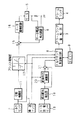
図1は、第1,3発明に係る電動パワーステアリング装置の実施の形態の要部構成を示すブロック図である。この電動パワーステアリング装置は、操舵軸(図示せず)に設けたトルクセンサ2の出力である操舵トルク信号を周期的にサンプリングし、そのサンプリングされた操舵トルク信号は、位相補償部11により位相補償され、アシスト制御部12に与えられる。
【0030】
また、車速センサ7からの車速信号はアシスト制御部12と舵角中点演算部20とトルクセンサ異常検出部8とに与えられる。アシスト制御部12は、位相補償部11からの操舵トルク信号及び車速センサ7からの車速信号に基づき、アシスト制御(操舵補助制御)のための目標電流値を出力する。
一方、トルクセンサ2の出力である操舵トルク信号は、トルクセンサ異常検出部8にも与えられる。
【0031】
操舵力補助用のモータ5の回転数を検出するモータ回転センサ18からのモータ回転数信号が、相対舵角検出部19に与えられ、相対舵角検出部19は、このモータ回転数信号からハンドル(舵輪)の相対舵角を検出し、舵角中点演算部20と減算手段21に与える。
舵角中点演算部20は、与えられた相対舵角から、車両が直進するハンドルの舵角中点を演算し、その演算結果を減算手段21に与える。減算手段21は、与えられた演算結果を相対舵角から減算して、舵角中点からの舵角である絶対舵角を求め、その信号をトルクセンサ異常検出部8に与える。
【0032】
尚、本実施の形態では、操舵機構に連結されたモータ5の回転数に基づいて、相対舵角を検出する例を示したが、モータ5の回転数に代えて、例えば、ロータリエンコーダを用いてハンドルに連結された操舵軸の回転数を検出して、相対舵角を検出してもよい。また、相対舵角検出値を用いて絶対舵角を検出する方法に代えて、直接、絶対舵角を検出してもよい。
【0033】
減算手段15は、アシスト制御部12からの目標電流値と、モータ電流検出回路6によって検出されたモータ5の駆動電流のフィードバック値との偏差を求め、この偏差をモータ駆動回路16に与える。モータ駆動回路16は、この偏差に基づきモータへの印加電圧を決定し、モータ5に与えて回転駆動させる。
トルクセンサ異常検出部8は、車速センサ7が検出した車速が所定車速より高く、減算手段21から与えられた絶対舵角が所定範囲内にあるときに、トルクセンサ2の出力である操舵トルク信号の値を、タイマー9が計時する所定時間積算し、その積算値の絶対値と所定値とを比較し、積算値の絶対値が所定値以上のときに、トルクセンサ2は故障しているとして、アラームランプ駆動部3を介してアラームランプ4を点灯させる。
【0034】
以下に、このような構成の電動パワーステアリング装置の制御動作を、それを示す図2のフローチャートを参照しながら説明する。
まず、トルクセンサ異常検出部8は、タイマー9が作動中(計時中又は計時終了信号出力中)であるか否かを調べ(S1)、作動中でないときは、出力積算値Sを0にして(S3)、タイマー9に計時を開始させる(S5)。
次に、トルクセンサ異常検出部8は、車速センサ7からの車速(信号)を読込み(S7)、その車速が所定値以上か否かを調べる(S9)。その車速が所定値以上のときは、減算手段21から絶対舵角を読込み(S11)、その絶対舵角が所定範囲内であるか否かを調べる(S13)。
【0035】
トルクセンサ異常検出部8は、その絶対舵角が所定範囲内であるときは、トルクセンサ2からの操舵トルク信号の値Trを読込み(S15)、積算値Sに加える(S17)。
トルクセンサ異常検出部8は、車速が所定値未満であるとき(S9)又は絶対舵角が所定範囲内でないとき(S13)はリターンする。
【0036】
トルクセンサ異常検出部8は、タイマー9が作動中(S1)で計時を終了しているとき(S19)、積算値Sの絶対値と所定値とを比較する(S21)。その結果、積算値Sの絶対値が所定値以上のときは、トルクセンサ2は故障しているとして、アラームランプ駆動部3を介してアラームランプ4を点灯させる(S23)。積算値Sの絶対値が所定値未満のとき(S21)はリターンする。
【0037】
図3は、第2,3発明に係る電動パワーステアリング装置の動作を示すフローチャートである。第2,3発明に係る電動パワーステアリング装置の実施の形態の要部構成は、上述した第1,3発明に係る電動パワーステアリング装置の実施の形態の要部構成と同様であるので、説明を省略する。
但し、トルクセンサ異常検出部8は、車速センサ7が検出した車速が所定車速より高く、減算手段21から与えられた絶対舵角が所定範囲内にあるときに、トルクセンサ2からの操舵トルク信号の値Trを、タイマー9が計時する所定時間積算し、その積算値から求めた操舵トルク信号の平均値とトルクセンサ2が中立点において出力すべき値との差を演算し、その差の絶対値と所定値とを比較し、差の絶対値が所定値以上のときに、トルクセンサ2は故障しているとして、アラームランプ駆動部3を介してアラームランプ4を点灯させる。
【0038】
以下に、第2,3発明に係る電動パワーステアリング装置の動作を、図3のフローチャートを参照しながら説明する。
まず、トルクセンサ異常検出部8は、タイマー9が作動中(計時中又は計時終了信号出力中)であるか否かを調べ(S1)、作動中でないときは、出力積算値Sを0にし(S3)、その積算した回数Nを0にして(S4)、タイマー9に計時を開始させる(S5)。
【0039】
次に、トルクセンサ異常検出部8は、車速センサ7からの車速(信号)を読込み(S7)、その車速が所定値以上か否かを調べる(S9)。その車速が所定値以上のときは、減算手段21から絶対舵角を読込み(S11)、その絶対舵角が所定範囲内であるか否かを調べる(S13)。
トルクセンサ異常検出部8は、その絶対舵角が所定範囲内であるときは、トルクセンサ2からの操舵トルク信号の値Trを読込み(S15)、積算値Sに加え(S17)、回数Nに1を加える(S18)。
【0040】
トルクセンサ異常検出部8は、車速が所定値未満であるとき(S9)又は絶対舵角が所定範囲内でないとき(S13)はリターンする。
トルクセンサ異常検出部8は、タイマー9が作動中(S1)で計時を終了しているとき(S19)、積算値Sと回数Nとから、操舵トルク信号Trの平均値M=S/Nを演算し(S20)、次に、トルクセンサ2が中立点において出力すべき値Cと平均値Mとの差E(=C−M)を演算する(S20a)。
次に、トルクセンサ異常検出部8は、差Eの絶対値と所定値とを比較し(S22)、その結果、差Eの絶対値が所定値以上のときは、トルクセンサ2は故障していると判断し、アラームランプ駆動部3を介してアラームランプ4を点灯させる(S23)。差Eの絶対値が所定値未満のとき(S22)はリターンする。
【0041】
図4は、第1,4発明に係る電動パワーステアリング装置の実施の形態の要部構成を示すブロック図である。この電動パワーステアリング装置では、車速センサ7からの車速信号はアシスト制御部12に与えられる。
操舵力補助用のモータ5の回転数を検出するモータ回転センサ18からのモータ回転数信号は、相対舵角検出部19に与えられ、相対舵角検出部19は、このモータ回転数信号からハンドル(舵輪)の相対舵角を検出し、舵角速度検出部24に与える。舵角速度検出部24は、与えられた相対舵角から、舵角速度を演算し、その演算結果をトルクセンサ異常検出部8aに与える。
【0042】
トルクセンサ異常検出部8aは、舵角速度検出部24が検出した舵角速度が所定舵角速度より低いときに、トルクセンサ2からの操舵トルク信号の値Trを、タイマー9が計時する所定時間積算し、その積算値の絶対値と所定値とを比較し、積算値の絶対値が所定値以上のときに、トルクセンサ2は故障していると判断し、アラームランプ駆動部3を介してアラームランプ4を点灯させる。その他の構成は、上述した第1,3発明に係る電動パワーステアリング装置の要部構成と同様であるので、説明を省略する。
【0043】
以下に、このような構成の電動パワーステアリング装置の動作を、それを示す図5のフローチャートを参照しながら説明する。
まず、トルクセンサ異常検出部8aは、タイマー9が作動中であるか否かを調べ(S25)、作動中でないときは、出力積算値を0にして(S27)、タイマー9に計時を開始させる(S29)。
【0044】
次に、トルクセンサ異常検出部8aは、舵角速度検出部24からの舵角速度を読込み(S31)、その舵角速度が所定値以下か否かを調べる(S33)。その舵角速度が所定値以下のときは、トルクセンサ2からの操舵トルク信号の値Trを読込み(S35)、積算値Sに加える(S37)。
トルクセンサ異常検出部8aは、舵角速度が所定値を超えるとき(S33)はリターンする。
【0045】
トルクセンサ異常検出部8aは、タイマー9が作動中(S25)で計時を終了しているとき(S39)、積算値Sの絶対値と所定値とを比較する(S41)。その結果、積算値Sの絶対値が所定値以上のときは、トルクセンサ2は故障していると判断し、アラームランプ駆動部3を介してアラームランプ4を点灯させる(S43)。積算値Sの絶対値が所定値未満のとき(S41)はリターンする。
【0046】
図6は、第2,4発明に係る電動パワーステアリング装置の動作を示すフローチャートである。第2,4発明に係る電動パワーステアリング装置の実施の形態の要部構成は、上述した第1,4発明に係る電動パワーステアリング装置の実施の形態の要部構成と同様であるので、説明を省略する。
但し、トルクセンサ異常検出部8aは、舵角速度検出部24が検出した舵角速度が所定舵角速度以下のときに、トルクセンサ2からの操舵トルク信号の値Trを、タイマー9が計時する所定時間積算し、その積算値から求めた操舵トルク信号の平均値とトルクセンサ2が中立点において出力すべき値との差を演算し、その差の絶対値と所定値とを比較し、差の絶対値が所定値以上のときに、トルクセンサ2は故障しているとして、アラームランプ駆動部3を介してアラームランプ4を点灯させる。
【0047】
以下に、第2,4発明に係る電動パワーステアリング装置の動作を、図6のフローチャートを参照しながら説明する。
まず、トルクセンサ異常検出部8aは、タイマー9が作動中であるか否かを調べ(S25)、作動中でないときは、出力積算値Sを0にし(S27)、その積算した回数Nを0にして(S28)、タイマー9に計時を開始させる(S29)。
【0048】
次に、トルクセンサ異常検出部8aは、舵角速度検出部24からの舵角速度を読込み(S31)、その舵角速度が所定値以下か否かを調べる(S33)。その舵角速度が所定値以下のときは、トルクセンサ2からの操舵トルク信号の値Trを読込み(S35)、積算値Sに加え(S37)、回数Nに1を加える(S38)。
トルクセンサ異常検出部8aは、舵角速度が所定値を超えるとき(S33)はリターンする。
【0049】
トルクセンサ異常検出部8aは、タイマー9が作動中(S25)で計時を終了しているとき(S39)、積算値Sと回数Nとから、操舵トルク信号Trの平均値M=S/Nを演算し(S40)、次に、トルクセンサ2が中立点において出力すべき値Cと平均値Mとの差E(=C−M)を演算する(S40a)。
次に、トルクセンサ異常検出部8は、差Eの絶対値と所定値とを比較し(S42)、その結果、差Eの絶対値が所定値以上のときは、トルクセンサ2は故障していると判断し、アラームランプ駆動部3を介してアラームランプ4を点灯させる(S43)。差Eの絶対値が所定値未満のとき(S42)はリターンする。
【0050】
図7は、第5〜9発明に係る電動パワーステアリング装置の実施の形態の要部構成を示すブロック図である。この電動パワーステアリング装置では、車速センサ7からの車速信号はアシスト制御部12に与えられる。
エンジンキー(図示せず)のオン又はオフを検知するエンジンキーオン/オフ検知部10からの検知信号が、トルクセンサ異常検出部8bに与えられる。
【0051】
トルクセンサ異常検出部8bは、エンジンキーオン/オフ検知部10がエンジンキーのオン動作を検知したときの、トルクセンサ2の出力値が所定範囲内にあるとき、その出力値を積算し、その積算した回数が所定の回数に達したときに、その積算値の絶対値と所定値とを比較し、積算値の絶対値が所定値以上のときに、トルクセンサ2は故障していると判断し、アラームランプ駆動部3を介してアラームランプ4を点灯させる。その他の構成は、上述した第1,3発明に係る電動パワーステアリング装置の要部構成と同様であるので、説明を省略する。
【0052】
以下に、このような構成の電動パワーステアリング装置の動作を、それを示す図8のフローチャートを参照しながら説明する。
まず、トルクセンサ異常検出部8bは、出力積算値Sを0にし(S45)、その積算した回数Nを0にする(S47)。
次に、トルクセンサ異常検出部8bは、回数Nが所定の回数に達したか否かを調べ(S49)、所定の回数に達していないときは、エンジンキーオン/オフ検知部10からエンジンキーのオン動作の検知信号が入力される迄待機する(S51)。
【0053】
トルクセンサ異常検出部8bは、エンジンキーオン/オフ検知部10からエンジンキーのオン動作の検知信号が入力されたとき(S51)、トルクセンサ2からの操舵トルク信号の値Trを読込み(S53)、その値Trの絶対値が所定値以上か否かを調べる(S55)。
トルクセンサ異常検出部8bは、その値Trの絶対値が所定値以上でないとき(所定範囲内のとき)、その値Trを積算値Sに加える(S57)。
【0054】
次に、トルクセンサ異常検出部8bは、回数Nに1を加えて(S59)、回数Nが所定の回数に達したか否かを調べる(S49)。
トルクセンサ異常検出部8bは、回数Nが所定の回数に達したときは(S49)、積算値Sの絶対値と所定値とを比較し(S63)、積算値Sの絶対値が所定値以上のときに、トルクセンサ2は故障していると判断し、アラームランプ駆動部3を介してアラームランプ4を点灯させる(S65)。積算値Sの絶対値が所定値未満のとき(S63)はS45に戻る。
【0055】
図9は、第6,9発明に係る電動パワーステアリング装置の動作を示すフローチャートである。第6,9発明に係る電動パワーステアリング装置の実施の形態の要部構成は、上述した第5,9発明に係る電動パワーステアリング装置の実施の形態の要部構成と同様であるので、説明を省略する。
但し、トルクセンサ異常検出部8bは、エンジンキーオン/オフ検知部10がエンジンキーのオン動作を検知したときの、トルクセンサ2の出力が所定範囲内にあるとき、その出力値を積算し、その積算した回数が所定の回数に達したときに、その積算値から出力値の平均値Mを求める。次いで、トルクセンサ2が中立点において出力すべき値Cと平均値Mとの差を演算し、その差の絶対値と所定値とを比較して、差の絶対値が所定値以上のときに、トルクセンサ2は故障しているとして、アラームランプ駆動部3を介してアラームランプ4を点灯させる。
【0056】
まず、トルクセンサ異常検出部8bは、出力積算値Sを0にし(S45)、その積算した回数Nを0にする(S47)。
次に、トルクセンサ異常検出部8bは、回数Nが所定の回数に達したか否かを調べ(S49)、所定の回数に達していないときは、エンジンキーオン/オフ検知部10からエンジンキーのオン動作の検知信号が入力される迄待機する(S51)。
【0057】
トルクセンサ異常検出部8bは、エンジンキーオン/オフ検知部10からエンジンキーのオン動作の検知信号が入力されたとき(S51)、トルクセンサ2の出力である操舵トルク信号の値Trを読込み(S53)、その値Trの絶対値が所定値以上か否かを調べる(S55)。
トルクセンサ異常検出部8bは、その値Trの絶対値が所定値以上でないとき(所定範囲内のとき)、その値Trを積算値Sに加える(S57)。
【0058】
次に、トルクセンサ異常検出部8bは、回数Nに1を加えて(S59)、回数Nが所定の回数に達したか否かを調べる(S49)。
トルクセンサ異常検出部8bは、回数Nが所定の回数に達したときは(S49)、操舵トルク信号Trの平均値M(=S/N)を演算し(S61)、次に、トルクセンサ2が中立点において出力すべき値Cと平均値Mとの差E(=C−M)を演算する(S62)。
次に、トルクセンサ異常検出部8bは、差Eの絶対値と所定値とを比較し(S64)、その結果、差Eの絶対値が所定値以上のときは、トルクセンサ2は故障しているとして、アラームランプ駆動部3を介してアラームランプ4を点灯させる(S65)。差Eの絶対値が所定値未満のとき(S64)はS45に戻る。
【0059】
図10は、第7,9発明に係る電動パワーステアリング装置の動作を示すフローチャートである。第7,9発明に係る電動パワーステアリング装置の実施の形態の要部構成は、上述した第5,9発明に係る電動パワーステアリング装置の実施の形態の要部構成と同様であるので、説明を省略する。
但し、エンジンキーオン/オフ検知部10からトルクセンサ異常検出部8bに与えられるのは、エンジンキーのオフ動作の検知信号となる。
【0060】
以下に、第7,9発明に係る電動パワーステアリング装置の動作を、図10のフローチャートを参照しながら説明する。
まず、トルクセンサ異常検出部8bは、出力積算値Sを0にし(S67)、その積算した回数Nを0にする(S69)。
次に、トルクセンサ異常検出部8bは、回数Nが所定の回数に達したか否かを調べ(S71)、所定の回数に達していないときは、エンジンキーオン/オフ検知部10からエンジンキーのオフ動作の検知信号が入力される迄待機する(S73)。
【0061】
トルクセンサ異常検出部8bは、エンジンキーオン/オフ検知部10からエンジンキーのオフ動作の検知信号が入力されたとき(S73)、トルクセンサ2からの操舵トルク信号の値Trを読込み(S75)、その値Trの絶対値が所定値以上か否かを調べる(S77)。
トルクセンサ異常検出部8bは、その値Trの絶対値が所定値以上でないとき(所定範囲内のとき)、その値Trを積算値Sに加える(S79)。
【0062】
次に、トルクセンサ異常検出部8bは、積算した操舵トルク信号の回数Nに1を加えて(S81)、回数Nが所定の回数に達したか否かを調べる(S71)。
トルクセンサ異常検出部8bは、回数Nが所定の回数に達したとき(S71)は、積算値Sの絶対値と所定値とを比較し(S85)、積算値の絶対値が所定値以上のときに、トルクセンサ2は故障しているとして、アラームランプ駆動部3を介してアラームランプ4を点灯させる(S87)。積算値Sの絶対値が所定値未満のときは(S85)S67に戻る。
【0063】
図11は、第8,9発明に係る電動パワーステアリング装置の動作を示すフローチャートである。第8,9発明に係る電動パワーステアリング装置の実施の形態の要部構成は、上述した第5,9発明に係る電動パワーステアリング装置の実施の形態の要部構成と同様であるので、説明を省略する。
但し、トルクセンサ異常検出部8bは、エンジンキーオン/オフ検知部10がエンジンキーのオフ動作を検知したときの、トルクセンサ2の出力が所定範囲内にあるとき、その出力値を積算し、その積算した回数が所定の回数に達したときに、その積算値から出力値の平均値Mを求める。次いで、トルクセンサ2が中立点において出力すべき値Cと平均値Mとの差を演算し、その差の絶対値と所定値とを比較して、差の絶対値が所定値以上のときに、トルクセンサ2は故障しているとして、アラームランプ駆動部3を介してアラームランプ4を点灯させる。
【0064】
まず、トルクセンサ異常検出部8bは、出力積算値Sを0にし(S67)、その積算した回数Nを0にする(S69)。
次に、トルクセンサ異常検出部8bは、回数Nが所定の回数に達したか否かを調べ(S71)、所定の回数に達していないときは、エンジンキーオン/オフ検知部10からエンジンキーのオフ動作の検知信号が入力される迄待機する(S73)。
【0065】
トルクセンサ異常検出部8bは、エンジンキーオン/オフ検知部10からエンジンキーのオフ動作の検知信号が入力されたとき(S73)、トルクセンサ2の出力である操舵トルク信号の値Trを読込み(S75)、その値Trの絶対値が所定値以上か否かを調べる(S77)。
トルクセンサ異常検出部8bは、その値Trの絶対値が所定値以上でないとき(所定範囲内のとき)、その値Trを積算値Sに加える(S79)。
【0066】
次に、トルクセンサ異常検出部8bは、回数Nに1を加えて(S81)、回数Nが所定の回数に達したか否かを調べる(S71)。
トルクセンサ異常検出部8bは、回数Nが所定の回数に達したときは(S71)、操舵トルク信号Trの平均値M(=S/N)を演算し(S83)、次に、トルクセンサ2が中立点において出力すべき値Cと平均値Mとの差E(=C−M)を演算する(S84)。
次に、トルクセンサ異常検出部8bは、差Eの絶対値と所定値とを比較し(S86)、その結果、差Eの絶対値が所定値以上のときは、トルクセンサ2は故障しているとして、アラームランプ駆動部3を介してアラームランプ4を点灯させる(S87)。差Eの絶対値が所定値未満のとき(S86)はS67に戻る。
【0067】
図12は、第10発明に係る電動パワーステアリング装置の実施の形態の要部構成を示すブロック図である。この電動パワーステアリング装置では、車速センサ7からの車速信号はアシスト制御部12に与えられる。
トルクセンサ2が機械的ストッパーに達したことを検知するストッパー検知部17のその検知信号が、トルクセンサ異常検出部8cに与えられる。
【0068】
トルクセンサ異常検出部8cは、ストッパー検知部17が、トルクセンサ2が機械的ストッパーに達したことを検知したときの、トルクセンサ2の出力値を記憶しておく。以後、ストッパー検知部17が前記達したことを検知する都度、そのときのトルクセンサ2の出力値と記憶しておいた出力値との差を演算し、次いで、その差の絶対値と所定値とを比較して、差の絶対値が所定値以上のときに、トルクセンサ2は故障していると判断し、アラームランプ駆動部3を介してアラームランプ4を点灯させる。その他の構成は、上述した第1,3発明に係る電動パワーステアリング装置の要部構成と同様であるので、説明を省略する。
【0069】
以下に、このような構成の電動パワーステアリング装置の動作を、それを示す図13のフローチャートを参照しながら説明する。
まず、トルクセンサ異常検出部8cは、ストッパー検知部17からその検知信号を与えられたとき(S89)、トルクセンサ2の出力値Trを読み込み(S91)、その出力値Trを記憶しておく(S93)。
【0070】
次に、トルクセンサ異常検出部8cは、ストッパー検知部17からその検知信号を与えられたとき(S95)、そのときのトルクセンサ2の出力値Trnを読込み(S97)、記憶しておいた出力値Trと読込んだ出力値Trnとの差を演算する(S99)。次いで、その差の絶対値と所定値とを比較して(S101)、その差の絶対値が所定値以上のときに、トルクセンサ2は故障しているとして、アラームランプ駆動部3を介してアラームランプ4を点灯させる(S103)。
トルクセンサ異常検出部8cは、その差の絶対値が所定値未満のとき(S101)、読込んだ出力値Trnを消去して(S105)、ストッパー検知部17から次にその検知信号を与えられる迄待機する(S95)。
【0071】
【発明の効果】
第1発明に係る電動パワーステアリング装置によれば、トルクセンサの出力の中立点の設定値が0である場合に、トルクセンサの測定の中立点の小さな移動変化でも検出することができる。
【0072】
第2発明に係る電動パワーステアリング装置によれば、トルクセンサの出力の中立点の設定値が0でない場合に、トルクセンサの測定の中立点の小さな移動変化でも検出することができる。
【0073】
第3,4発明に係る電動パワーステアリング装置によれば、車両が略直進している状態におけるトルクセンサの出力の小さな値が処理対象となり、トルクセンサの測定の中立点の小さな移動変化の検出精度を高めることができる。
【0074】
第5発明に係る電動パワーステアリング装置によれば、トルクセンサの出力の中立点の設定値が0である場合に、検知する手段がエンジンキーのオン動作を検知したときのトルクセンサの出力を積算するので、トルクセンサの出力の小さな値が処理対象となり、トルクセンサの測定の中立点の小さな移動変化の検出精度を高めることができる。
【0075】
第6発明に係る電動パワーステアリング装置によれば、トルクセンサの出力の中立点の設定値が0でない場合に、検知する手段がエンジンキーのオン動作を検知したときのトルクセンサの出力を積算し平均値を求めるので、トルクセンサの出力の小さな値が処理対象となり、トルクセンサの測定の中立点の小さな移動変化の検出精度を高めることができる。
【0076】
第7発明に係る電動パワーステアリング装置によれば、検知する手段がエンジンキーのオフ動作を検知したときのトルクセンサの出力を積算するので、トルクセンサの出力の中立点の設定値が0である場合に、トルクセンサの出力の小さな値が処理対象となり、トルクセンサの測定の中立点の小さな移動変化の検出精度を高めることができる。
【0077】
第8発明に係る電動パワーステアリング装置によれば、トルクセンサの出力の中立点の設定値が0でない場合に、検知する手段がエンジンキーのオフ動作を検知したときのトルクセンサの出力を積算し平均値を求めるので、トルクセンサの出力の小さな値が処理対象となり、トルクセンサの測定の中立点の小さな移動変化の検出精度を高めることができる。
【0078】
第9発明に係る電動パワーステアリング装置によれば、例外的な状態におけるトルクセンサの出力は積算されず、小さな値のみが処理対象となり、検出精度を高めることができる。
【0079】
第10発明に係る電動パワーステアリング装置によれば、トルクセンサが機械的ストッパーに到達したときのトルクセンサの出力は、略同一と考えられるので、そのときのズレを監視し、そのズレが所定値以上になれば、トルクセンサは故障していると判断できる。これにより、トルクセンサの測定の中立点の小さな移動変化でも検出することができる。
【図面の簡単な説明】
【図1】第1,3発明に係る電動パワーステアリング装置の実施の形態の要部構成を示すブロック図である。
【図2】第1,3発明に係る電動パワーステアリング装置の動作を示すフローチャートである。
【図3】第2,3発明に係る電動パワーステアリング装置の動作を示すフローチャートである。
【図4】第1,4発明に係る電動パワーステアリング装置の実施の形態の要部構成を示すブロック図である。
【図5】第1,4発明に係る電動パワーステアリング装置の動作を示すフローチャートである。
【図6】第2,4発明に係る電動パワーステアリング装置の動作を示すフローチャートである。
【図7】第5〜9発明に係る電動パワーステアリング装置の実施の形態の要部構成を示すブロック図である。
【図8】第5,9発明に係る電動パワーステアリング装置の動作を示すフローチャートである。
【図9】第6,9発明に係る電動パワーステアリング装置の動作を示すフローチャートである。
【図10】第7,9発明に係る電動パワーステアリング装置の動作を示すフローチャートである。
【図11】第8,9発明に係る電動パワーステアリング装置の動作を示すフローチャートである。
【図12】第10発明に係る電動パワーステアリング装置の実施の形態の要部構成を示すブロック図である。
【図13】第10発明に係る電動パワーステアリング装置の動作を示すフローチャートである。
【図14】従来の電動パワーステアリング装置の要部構成例を示すブロック図である。
【符号の説明】
2 トルクセンサ
4 アラームランプ
5 モータ
7 車速センサ
8,8a トルクセンサ異常検出部(積算手段)
8b トルクセンサ異常検出部(積算手段、演算手段、演算する手段、判定する手段、比較する手段)
8c トルクセンサ異常検出部(記憶手段、演算手段、演算する手段、比較する手段)
9 タイマー
10 エンジンキーオン/オフ検知部
12 アシスト制御部
17 ストッパー検知部(ストッパー検知手段)
18 モータ回転センサ(舵角検出手段、舵角速度検出手段)
19 相対舵角検出部(舵角検出手段、舵角速度検出手段)
20 舵角中点演算部(舵角検出手段)
21 減算手段(舵角検出手段)
24 舵角速度検出部(舵角速度検出手段)[0001]
BACKGROUND OF THE INVENTION
The present invention relates to an improvement in an electric power steering device that assists steering based on the output of a torque sensor that detects steering torque, and more particularly to failure detection of a torque sensor.
[0002]
[Prior art]
FIG. 14 is a block diagram illustrating a configuration example of a main part of a conventional electric power steering apparatus. In this electric power steering apparatus, the phase of the steering torque signal from the
Further, a vehicle speed signal from the
[0003]
The
[0004]
[Problems to be solved by the invention]
In the conventional electric power steering apparatus as described above, when an excessive input is applied to the
[0005]
As a prior art for a similar problem, the number of times the input torque enters a certain range is counted separately on the left and right, and it is determined that an abnormality has occurred when the difference between the left and right count values exceeds a certain level. “Fail-safe device for electric power steering device” is disclosed in Japanese Patent Application Laid-Open No. 1-178080, which can detect the abnormality only when the change in the neutral point of the measurement is large. is there.
The present invention has been made in view of the above-described circumstances, and an object thereof is to provide an electric power steering device that can detect even a small change in movement of a neutral point of measurement by a torque sensor.
[0006]
[Means for Solving the Problems]
An electric power steering apparatus according to a first aspect of the present invention is an electric power steering apparatus for assisting steering based on an output of a torque sensor for detecting a steering torque. An integrating means for integrating the output of the torque sensor for a predetermined time, and the integrating means And a means for comparing the absolute value of the integrated values with a predetermined value.
[0007]
In this electric power steering apparatus, the integrating means integrates the output of the torque sensor for a predetermined time. The means for comparing compares the absolute value of the integrated value with a predetermined value.
If the neutral point of the torque sensor output is zero, the integrated value of the torque sensor output should be substantially zero when viewed in a long operation time. Therefore, if the integrated value for a long predetermined time deviates from 0 by a predetermined value or more, it can be determined that the torque sensor has failed. Thereby, when the set value of the neutral point of the output of the torque sensor is 0, even a small movement change of the neutral point of the measurement of the torque sensor can be detected.
[0008]
According to a second aspect of the present invention, there is provided an electric power steering apparatus that periodically samples the output of a torque sensor that detects a steering torque, and in the electric power steering apparatus that assists steering based on the sampled output, an integration that integrates the output for a predetermined time. Means, counting means for counting the number of times integrated by the integrating means, calculating means for calculating the average value of the outputs from the integrated value integrated by the integrating means and the number of times counted by the counting means, and the torque sensor Comprises means for computing a difference between a value to be output at a neutral point and an average value computed by the computing means, and means for comparing the absolute value of the difference computed by the means with a predetermined value. To do.
[0009]
In this electric power steering apparatus, the output of the periodically sampled torque sensor is accumulated for a predetermined time, and the counting means counts the accumulated number of times. The calculating means calculates an average value of the output of the torque sensor from the integrated value integrated by the integrating means and the number of times counted by the counting means. The means for calculating the difference calculates the difference between the value that the torque sensor should output at the neutral point and the calculated average value, and the means for comparing compares the absolute value of the calculated difference with a predetermined value. .
[0010]
The average value of the output of the torque sensor should show a substantially neutral point when viewed over a long operation time. Therefore, if the average value of the output over a long predetermined time deviates from the neutral point by a predetermined value or more, it can be determined that the torque sensor has failed. Thereby, when the set value of the neutral point of the output of the torque sensor is not 0, even a small movement change of the neutral point of the torque sensor can be detected.
[0011]
An electric power steering apparatus according to a third aspect of the present invention includes a vehicle speed sensor that detects a vehicle speed and a steering angle detection means that detects a steering angle, and the vehicle speed detected by the vehicle speed sensor is higher than a predetermined vehicle speed, and the steering angle detection means When the rudder angle detected by is within a predetermined range, the integration means performs integration.
[0012]
In this electric power steering apparatus, when the vehicle speed detected by the vehicle speed sensor is higher than a predetermined vehicle speed and the steering angle detected by the steering angle detection means is within a predetermined range, the integration means integrates the output of the torque sensor. A small value of the output of the torque sensor in a state in which the motor is traveling substantially straight becomes a processing target, and it is possible to improve the detection accuracy of a small movement change at the neutral point of the torque sensor measurement.
[0013]
The electric power steering apparatus according to a fourth aspect of the present invention further includes a steering angular speed detection means for detecting a steering angular speed, and the integration means integrates when the steering angular speed detected by the steering angular speed detection means is lower than a predetermined steering angular speed. It is characterized by.
[0014]
In this electric power steering apparatus, when the steering angular speed detected by the steering angular speed detection means is lower than the predetermined steering angular speed, the integration means integrates the output of the torque sensor, so the output of the torque sensor in a state where the vehicle is running substantially straight A small value of is an object to be processed, and the detection accuracy of a small movement change at the neutral point of the torque sensor measurement can be improved.
[0015]
An electric power steering apparatus according to a fifth aspect of the present invention is the electric power steering apparatus for assisting steering based on the output of the torque sensor for detecting the steering torque, the means for detecting the on operation of the engine key, and a predetermined number of times. An integration unit that integrates the output of the torque sensor each time the ON operation is detected, and a unit that compares the absolute value of the integration value integrated by the integration unit with a predetermined value are provided.
[0016]
In this electric power steering apparatus, the detecting means detects the on-operation of the engine key, and the integrating means integrates the output of the torque sensor at the time of detection for a predetermined number of times. The means for comparing compares the absolute value of the integrated value with a predetermined value.
When the driver turns on the engine key, the driver often releases his / her hand from the steering wheel. Accordingly, when the setting value of the neutral point of the output of the torque sensor is 0, if the detecting means adds up the output of the torque sensor when the engine key ON operation is detected, a small value of the torque sensor output is obtained. It becomes an object to be processed, and it is possible to increase the detection accuracy of a small movement change at the neutral point of the torque sensor measurement.
[0017]
An electric power steering apparatus according to a sixth aspect of the invention is an electric power steering apparatus that assists steering based on an output of a torque sensor that detects a steering torque. A means for detecting an on operation of an engine key, a predetermined number of times, Each time the on-operation is detected, integrating means for integrating the output of the torque sensor, calculating means for calculating the average value of the outputs from the integrated value integrated by the integrating means, and the torque sensor outputting at a neutral point It is characterized by comprising means for calculating the difference between the power value and the average value calculated by the calculating means, and means for comparing the absolute value of the difference calculated by the means with a predetermined value.
[0018]
In this electric power steering apparatus, the detecting means detects the on operation of the engine key, and the integrating means integrates the output of the torque sensor when the on operation is detected a predetermined number of times. The computing means computes the average value of the output of the torque sensor from the integrated value, and the means for computing the difference computes the difference between the value that the torque sensor should output at the neutral point and the average value. Then, the comparing means compares the absolute value of the calculated difference with a predetermined value.
[0019]
When the driver turns on the engine key, the driver often releases his / her hand from the steering wheel. Therefore, when the setting value of the neutral point of the output of the torque sensor is not 0, if the means for detecting integrates the outputs of the torque sensor when the on-operation of the engine key is detected to obtain the average value, the output of the torque sensor A small value becomes a processing target, and the detection accuracy of a small movement change at the neutral point of the measurement of the torque sensor can be improved.
[0020]
According to a seventh aspect of the present invention, there is provided an electric power steering apparatus for assisting steering based on an output of a torque sensor for detecting a steering torque, wherein the means for detecting an off operation of the engine key, a predetermined number of times, An integration unit that integrates the output of the torque sensor each time the off-operation is detected, and a unit that compares the absolute value of the integration value integrated by the integration unit with a predetermined value.
[0021]
In this electric power steering apparatus, the detecting means detects the off operation of the engine key, and the integrating means integrates the output of the torque sensor at the time of detection for a predetermined number of times. The means for comparing compares the absolute value of the integrated value with a predetermined value.
When the driver turns off the engine key, the driver often releases his handle. Therefore, if the detection means integrates the output of the torque sensor when the engine key off operation is detected, when the neutral value set value of the output of the torque sensor is 0, a small value of the output of the torque sensor is obtained. It becomes an object to be processed, and it is possible to increase the detection accuracy of a small movement change at the neutral point of the torque sensor measurement.
[0022]
An electric power steering apparatus according to an eighth aspect of the present invention is the electric power steering apparatus for assisting steering based on the output of the torque sensor for detecting the steering torque, the means for detecting the off operation of the engine key, the predetermined number of times, Each time the OFF operation is detected, an integration unit that integrates the output of the torque sensor, an arithmetic unit that calculates an average value of the outputs from the integration value integrated by the integration unit, and the torque sensor that outputs at a neutral point It is characterized by comprising means for calculating the difference between the power value and the average value calculated by the calculating means, and means for comparing the absolute value of the difference calculated by the means with a predetermined value.
[0023]
In this electric power steering apparatus, the detecting means detects the off operation of the engine key, and the integrating means integrates the output of the torque sensor when the off operation is detected a predetermined number of times. The computing means computes the average value of the torque sensor output from the integrated value, and the means for computing the difference computes the difference between the value that the torque sensor should output at the neutral point and the average value. Then, the comparing means compares the absolute value of the difference with a predetermined value.
[0024]
When the driver turns off the engine key, the driver often releases his handle. Therefore, when the setting value of the neutral point of the output of the torque sensor is not 0, if the means for detecting integrates the output of the torque sensor when the off-operation of the engine key is detected to obtain the average value, the output of the torque sensor A small value becomes a processing target, and the detection accuracy of a small movement change at the neutral point of the measurement of the torque sensor can be improved.
[0025]
An electric power steering apparatus according to a ninth aspect of the present invention comprises means for determining whether or not the output of the torque sensor is within a predetermined range, and when the means determines that the output is within a predetermined range, The integrating means is characterized by integrating.
[0026]
In this electric power steering apparatus, when the determining means determines that the output of the torque sensor is within a predetermined range, the integrating means integrates. Therefore, when the engine key is turned on or off, the driver exceptionally The output of a large torque sensor as when a force is applied to the handle is not integrated. Therefore, the output of the torque sensor in an exceptional state is not integrated, and only a small value is processed, and the detection accuracy can be improved.
[0027]
An electric power steering apparatus according to a tenth aspect of the present invention is the electric power steering apparatus for assisting steering based on the output of a torque sensor that has a mechanical stopper for preventing run-out and detects steering torque. Stopper detecting means for detecting the arrival at the mechanical stopper, storage means for storing the output of the torque sensor when the stopper detecting means detects the arrival, and the stopper detecting means after the arrival of the torque sensor Means for calculating a difference between the output of the torque sensor when the arrival at the mechanical stopper is detected and the output stored in the storage means; and an absolute value of the difference calculated by the means and a predetermined value. And means for comparing.
[0028]
In this electric power steering apparatus, the stopper detection means detects the arrival of the torque sensor to the mechanical stopper. The storage means stores the output of the torque sensor when it is detected. The calculating means calculates the difference between the output of the torque sensor when the stopper detecting means detects the arrival of the torque sensor to the mechanical stopper after the arrival and the output stored in the storage means. The comparing means compares the absolute value of the difference calculated by the calculating means with a predetermined value.
The torque sensor output when the torque sensor reaches the mechanical stopper is considered to be substantially the same, so the deviation at that time is monitored, and if the deviation exceeds a predetermined value, the torque sensor has failed. I can judge. Thereby, even a small movement change of the neutral point of the measurement of the torque sensor can be detected.
[0029]
DETAILED DESCRIPTION OF THE INVENTION
Embodiments of an electric power steering apparatus according to the present invention will be described below with reference to the drawings showing the embodiments.
FIG. 1 is a block diagram showing a main configuration of an embodiment of an electric power steering apparatus according to the first and third inventions. This electric power steering apparatus periodically samples a steering torque signal, which is an output of a
[0030]
The vehicle speed signal from the
On the other hand, the steering torque signal that is the output of the
[0031]
A motor rotation speed signal from a
The steering
[0032]
In the present embodiment, an example in which the relative rudder angle is detected based on the rotation speed of the
[0033]
The subtracting
The torque sensor
[0034]
Hereinafter, the control operation of the electric power steering apparatus having such a configuration will be described with reference to the flowchart of FIG.
First, the torque
Next, the torque sensor
[0035]
When the absolute steering angle is within the predetermined range, the torque sensor
The torque sensor
[0036]
The torque sensor
[0037]
FIG. 3 is a flowchart showing the operation of the electric power steering apparatus according to the second and third aspects of the invention. The main configuration of the electric power steering apparatus according to the second and third aspects of the embodiment is the same as the main configuration of the electric power steering apparatus according to the first and third aspects of the invention described above. Omitted.
However, the torque sensor
[0038]
The operation of the electric power steering apparatus according to the second and third aspects of the invention will be described below with reference to the flowchart of FIG.
First, the torque sensor
[0039]
Next, the torque sensor
When the absolute steering angle is within the predetermined range, the torque sensor
[0040]
The torque sensor
When the
Next, the torque sensor
[0041]
FIG. 4 is a block diagram showing a main configuration of an embodiment of the electric power steering apparatus according to the first and fourth inventions. In this electric power steering apparatus, a vehicle speed signal from the
A motor rotation speed signal from a
[0042]
The torque sensor abnormality detection unit 8a integrates the value Tr of the steering torque signal from the
[0043]
Hereinafter, the operation of the electric power steering apparatus having such a configuration will be described with reference to the flowchart of FIG.
First, the torque sensor abnormality detection unit 8a checks whether or not the
[0044]
Next, the torque sensor abnormality detection unit 8a reads the steering angular velocity from the steering angular velocity detection unit 24 (S31), and checks whether the steering angular velocity is equal to or less than a predetermined value (S33). When the steering angular velocity is less than or equal to a predetermined value, the value Tr of the steering torque signal from the
The torque sensor abnormality detection unit 8a returns when the steering angular velocity exceeds a predetermined value (S33).
[0045]
When the
[0046]
FIG. 6 is a flowchart showing the operation of the electric power steering apparatus according to the second and fourth inventions. The main configuration of the electric power steering apparatus according to the second and fourth inventions is the same as the main configuration of the electric power steering apparatus according to the first and fourth inventions. Omitted.
However, the torque sensor abnormality detection unit 8a integrates the value Tr of the steering torque signal from the
[0047]
The operation of the electric power steering apparatus according to the second and fourth inventions will be described below with reference to the flowchart of FIG.
First, the torque sensor abnormality detection unit 8a checks whether or not the
[0048]
Next, the torque sensor abnormality detection unit 8a reads the steering angular velocity from the steering angular velocity detection unit 24 (S31), and checks whether the steering angular velocity is equal to or less than a predetermined value (S33). When the steering angular velocity is equal to or less than the predetermined value, the value Tr of the steering torque signal from the
The torque sensor abnormality detection unit 8a returns when the steering angular velocity exceeds a predetermined value (S33).
[0049]
When the
Next, the torque sensor
[0050]
FIG. 7 is a block diagram showing a main configuration of an embodiment of the electric power steering apparatus according to the fifth to ninth inventions. In this electric power steering apparatus, a vehicle speed signal from the
A detection signal from an engine key on / off
[0051]
The torque sensor abnormality detection unit 8b integrates the output value when the output value of the
[0052]
Hereinafter, the operation of the electric power steering apparatus having such a configuration will be described with reference to the flowchart of FIG.
First, the torque sensor abnormality detection unit 8b sets the output integrated value S to 0 (S45), and sets the integrated number N to 0 (S47).
Next, the torque sensor abnormality detection unit 8b checks whether or not the number N of times has reached a predetermined number (S49). If the number has not reached the predetermined number, the engine key on / off
[0053]
When the engine key on / off detection signal is input from the engine key on / off detection unit 10 (S51), the torque sensor abnormality detection unit 8b reads the value Tr of the steering torque signal from the torque sensor 2 (S53), It is checked whether the absolute value of the value Tr is equal to or greater than a predetermined value (S55).
When the absolute value of the value Tr is not equal to or greater than the predetermined value (when it is within the predetermined range), the torque sensor abnormality detection unit 8b adds the value Tr to the integrated value S (S57).
[0054]
Next, the torque sensor abnormality detection unit 8b adds 1 to the number N (S59) and checks whether the number N has reached a predetermined number (S49).
When the number N of times reaches a predetermined number (S49), the torque sensor abnormality detection unit 8b compares the absolute value of the integrated value S with a predetermined value (S63), and the absolute value of the integrated value S is equal to or greater than the predetermined value. At this time, it is determined that the
[0055]
FIG. 9 is a flowchart showing the operation of the electric power steering apparatus according to the sixth and ninth inventions. The main configuration of the electric power steering apparatus according to the sixth and ninth inventions is the same as the main configuration of the above-described electric power steering apparatus according to the fifth and ninth inventions. Omitted.
However, the torque sensor abnormality detection unit 8b integrates the output value when the output of the
[0056]
First, the torque sensor abnormality detection unit 8b sets the output integrated value S to 0 (S45), and sets the integrated number N to 0 (S47).
Next, the torque sensor abnormality detection unit 8b checks whether or not the number N of times has reached a predetermined number (S49). If the number has not reached the predetermined number, the engine key on / off
[0057]
When the engine key on / off detection signal is input from the engine key on / off detection unit 10 (S51), the torque sensor abnormality detection unit 8b reads the value Tr of the steering torque signal that is the output of the torque sensor 2 (S53). ), It is checked whether the absolute value of the value Tr is equal to or greater than a predetermined value (S55).
When the absolute value of the value Tr is not equal to or greater than the predetermined value (when it is within the predetermined range), the torque sensor abnormality detection unit 8b adds the value Tr to the integrated value S (S57).
[0058]
Next, the torque sensor abnormality detection unit 8b adds 1 to the number N (S59) and checks whether the number N has reached a predetermined number (S49).
When the number N of times reaches a predetermined number (S49), the torque sensor abnormality detection unit 8b calculates an average value M (= S / N) of the steering torque signal Tr (S61), and then the
Next, the torque sensor abnormality detection unit 8b compares the absolute value of the difference E with a predetermined value (S64). As a result, if the absolute value of the difference E is equal to or larger than the predetermined value, the
[0059]
FIG. 10 is a flowchart showing the operation of the electric power steering apparatus according to the seventh and ninth inventions. The main configuration of the electric power steering apparatus according to the seventh and ninth inventions is the same as the main configuration of the above-described electric power steering apparatus according to the fifth and ninth inventions. Omitted.
However, what is given from the engine key on / off
[0060]
The operation of the electric power steering apparatus according to the seventh and ninth inventions will be described below with reference to the flowchart of FIG.
First, the torque sensor abnormality detection unit 8b sets the output integrated value S to 0 (S67), and sets the integrated number N to 0 (S69).
Next, the torque sensor abnormality detection unit 8b checks whether or not the number N of times has reached a predetermined number (S71). If the number N has not reached the predetermined number, the engine key on / off
[0061]
The torque sensor abnormality detection unit 8b reads the value Tr of the steering torque signal from the torque sensor 2 (S75) when the detection signal of the engine key off operation is input from the engine key on / off detection unit 10 (S73). It is checked whether or not the absolute value of the value Tr is greater than or equal to a predetermined value (S77).
The torque sensor abnormality detection unit 8b adds the value Tr to the integrated value S when the absolute value of the value Tr is not equal to or greater than the predetermined value (within a predetermined range) (S79).
[0062]
Next, the torque sensor abnormality detection unit 8b adds 1 to the accumulated number N of steering torque signals (S81), and checks whether the number N has reached a predetermined number (S71).
When the number N of times reaches the predetermined number (S71), the torque sensor abnormality detection unit 8b compares the absolute value of the integrated value S with the predetermined value (S85), and the absolute value of the integrated value is equal to or greater than the predetermined value. When the
[0063]
FIG. 11 is a flowchart showing the operation of the electric power steering apparatus according to the eighth and ninth inventions. The main configuration of the electric power steering apparatus according to the eighth and ninth inventions is the same as the main configuration of the electric power steering apparatus according to the fifth and ninth inventions. Omitted.
However, the torque sensor abnormality detection unit 8b integrates the output value when the output of the
[0064]
First, the torque sensor abnormality detection unit 8b sets the output integrated value S to 0 (S67), and sets the integrated number N to 0 (S69).
Next, the torque sensor abnormality detection unit 8b checks whether or not the number N of times has reached a predetermined number (S71). If the number N has not reached the predetermined number, the engine key on / off
[0065]
The torque sensor abnormality detection unit 8b reads the value Tr of the steering torque signal, which is the output of the
The torque sensor abnormality detection unit 8b adds the value Tr to the integrated value S when the absolute value of the value Tr is not equal to or greater than the predetermined value (within a predetermined range) (S79).
[0066]
Next, the torque sensor abnormality detection unit 8b adds 1 to the number N (S81) and checks whether the number N has reached a predetermined number (S71).
When the number N of times reaches a predetermined number (S71), the torque sensor abnormality detection unit 8b calculates an average value M (= S / N) of the steering torque signal Tr (S83), and then the
Next, the torque sensor abnormality detection unit 8b compares the absolute value of the difference E with a predetermined value (S86). As a result, if the absolute value of the difference E is equal to or larger than the predetermined value, the
[0067]
FIG. 12 is a block diagram showing the main configuration of an embodiment of the electric power steering apparatus according to the tenth invention. In this electric power steering apparatus, a vehicle speed signal from the
The detection signal of the
[0068]
The torque sensor
[0069]
Hereinafter, the operation of the electric power steering apparatus having such a configuration will be described with reference to the flowchart of FIG.
First, when the detection signal is given from the stopper detection unit 17 (S89), the torque sensor
[0070]
Next, when the detection signal is given from the stopper detection unit 17 (S95), the torque sensor
When the absolute value of the difference is less than the predetermined value (S101), the torque sensor
[0071]
【The invention's effect】
With the electric power steering apparatus according to the first aspect of the invention, even when the set value of the neutral point of the torque sensor output is 0, it is possible to detect even a small movement change of the neutral point of the torque sensor measurement.
[0072]
According to the electric power steering device of the second aspect of the present invention, even when the set value of the neutral point of the torque sensor output is not 0, it is possible to detect even a small movement change of the neutral point measured by the torque sensor.
[0073]
According to the electric power steering apparatus according to the third and fourth inventions, a small value of the output of the torque sensor in a state where the vehicle is traveling substantially straight becomes a processing target, and the detection accuracy of the movement change with a small neutral point measured by the torque sensor. Can be increased.
[0074]
According to the electric power steering device of the fifth aspect of the invention, when the setting value of the neutral point of the output of the torque sensor is 0, the output of the torque sensor when the detecting means detects the on operation of the engine key is integrated. Therefore, a small value of the output of the torque sensor becomes a processing target, and the detection accuracy of the movement change with a small neutral point of the measurement of the torque sensor can be improved.
[0075]
According to the electric power steering apparatus of the sixth aspect of the invention, when the neutral point set value of the torque sensor output is not 0, the detecting means integrates the output of the torque sensor when the on-operation of the engine key is detected. Since the average value is obtained, a small value of the output of the torque sensor becomes a processing target, and the detection accuracy of the small movement change at the neutral point of the torque sensor measurement can be improved.
[0076]
According to the electric power steering apparatus of the seventh aspect of the invention, since the detecting means integrates the output of the torque sensor when the off-operation of the engine key is detected, the setting value of the neutral point of the torque sensor output is 0. In this case, a small value of the output of the torque sensor becomes a processing target, and the detection accuracy of the small movement change of the neutral point measured by the torque sensor can be improved.
[0077]
According to the electric power steering device of the eighth aspect of the invention, when the setting value of the neutral point of the torque sensor output is not 0, the detecting means integrates the output of the torque sensor when the off-operation of the engine key is detected. Since the average value is obtained, a small value of the output of the torque sensor becomes a processing target, and the detection accuracy of the small movement change at the neutral point of the torque sensor measurement can be improved.
[0078]
According to the electric power steering apparatus according to the ninth aspect of the invention, the output of the torque sensor in an exceptional state is not integrated, and only a small value is processed, and the detection accuracy can be improved.
[0079]
According to the electric power steering apparatus according to the tenth aspect of the invention, since the output of the torque sensor when the torque sensor reaches the mechanical stopper is considered to be substantially the same, the deviation at that time is monitored, and the deviation is a predetermined value. If it becomes above, it can be judged that the torque sensor is out of order. Thereby, even a small movement change of the neutral point of the measurement of the torque sensor can be detected.
[Brief description of the drawings]
FIG. 1 is a block diagram showing a main configuration of an embodiment of an electric power steering apparatus according to first and third inventions.
FIG. 2 is a flowchart showing the operation of the electric power steering apparatus according to the first and third inventions.
FIG. 3 is a flowchart showing the operation of the electric power steering apparatus according to the second and third aspects of the invention.
FIG. 4 is a block diagram showing a main configuration of an embodiment of the electric power steering apparatus according to the first and fourth inventions.
FIG. 5 is a flowchart showing the operation of the electric power steering apparatus according to the first and fourth inventions.
FIG. 6 is a flowchart showing the operation of the electric power steering apparatus according to the second and fourth inventions.
FIG. 7 is a block diagram showing a main configuration of an embodiment of an electric power steering apparatus according to fifth to ninth inventions.
FIG. 8 is a flowchart showing the operation of the electric power steering apparatus according to the fifth and ninth inventions.
FIG. 9 is a flowchart showing the operation of the electric power steering apparatus according to the sixth and ninth inventions.
FIG. 10 is a flowchart showing the operation of the electric power steering apparatus according to the seventh and ninth inventions.
FIG. 11 is a flowchart showing the operation of the electric power steering apparatus according to the eighth and ninth inventions.
FIG. 12 is a block diagram showing a main configuration of an embodiment of an electric power steering device according to a tenth invention.
FIG. 13 is a flowchart showing the operation of the electric power steering apparatus according to the tenth invention.
FIG. 14 is a block diagram showing a configuration example of a main part of a conventional electric power steering apparatus.
[Explanation of symbols]
2 Torque sensor
4 Alarm lamp
5 Motor
7 Vehicle speed sensor
8, 8a Torque sensor abnormality detection unit (integrating means)
8b Torque sensor abnormality detector (integrating means, calculating means, calculating means, determining means, comparing means)
8c Torque sensor abnormality detector (storage means, calculation means, calculation means, comparison means)
9 Timer
10 Engine key on / off detector
12 Assist control unit
17 Stopper detection part (stopper detection means)
18 Motor rotation sensor (steering angle detection means, steering angle speed detection means)
19 Relative rudder angle detector (steer angle detector, rudder angular velocity detector)
20 Rudder angle midpoint calculator (steering angle detection means)
21 Subtraction means (steering angle detection means)
24 Rudder angular velocity detection part (steering angular velocity detection means)
Claims (10)
前記トルクセンサの出力を所定時間積算する積算手段と、該積算手段が積算した積算値の絶対値と所定値とを比較する手段とを備えることを特徴とする電動パワーステアリング装置。In an electric power steering device that assists steering based on the output of a torque sensor that detects steering torque,
An electric power steering apparatus comprising: an integrating unit that integrates the output of the torque sensor for a predetermined time; and a unit that compares an absolute value of the integrated value integrated by the integrating unit with a predetermined value.
前記出力を所定時間積算する積算手段と、該積算手段が積算した回数を計数する計数手段と、前記積算手段が積算した積算値と前記計数手段が計数した回数とから前記出力の平均値を演算する演算手段と、前記トルクセンサが中立点において出力すべき値と前記演算手段が演算した平均値との差を演算する手段と、該手段が演算した差の絶対値と所定値とを比較する手段とを備えることを特徴とする電動パワーステアリング装置。In the electric power steering device for assisting steering based on periodically sampling the output of the torque sensor for detecting the steering torque and based on the sampled output,
An integration means for integrating the output for a predetermined time; a counting means for counting the number of times that the integration means has accumulated; an integrated value that is integrated by the integration means; and an average value of the output is calculated from the number of times that the counting means has counted. A means for calculating, a means for calculating a difference between a value to be output by the torque sensor at a neutral point and an average value calculated by the calculating means, and an absolute value of the difference calculated by the means are compared with a predetermined value. And an electric power steering apparatus.
エンジンキーのオン動作を検知する手段と、所定の回数、該手段が前記オン動作を検知する都度、前記トルクセンサの出力を積算する積算手段と、該積算手段が積算した積算値の絶対値と所定値とを比較する手段とを備えることを特徴とする電動パワーステアリング装置。In an electric power steering device that assists steering based on the output of a torque sensor that detects steering torque,
A means for detecting an on operation of the engine key, an integration means for integrating the output of the torque sensor each time the means detects the on operation, and an absolute value of the integrated value integrated by the integration means; An electric power steering device comprising means for comparing with a predetermined value.
エンジンキーのオン動作を検知する手段と、所定の回数、該手段が前記オン動作を検知する都度、前記トルクセンサの出力を積算する積算手段と、該積算手段が積算した積算値から前記出力の平均値を演算する演算手段と、前記トルクセンサが中立点において出力すべき値と前記演算手段が演算した平均値との差を演算する手段と、該手段が演算した差の絶対値と所定値とを比較する手段とを備えることを特徴とする電動パワーステアリング装置。In an electric power steering device that assists steering based on the output of a torque sensor that detects steering torque,
A means for detecting an on-operation of the engine key; an integration means for integrating the output of the torque sensor each time the means detects the on-operation; and an output value from the integrated value integrated by the integration means. An arithmetic means for calculating an average value, means for calculating a difference between a value to be output by the torque sensor at a neutral point and an average value calculated by the arithmetic means, an absolute value of the difference calculated by the means, and a predetermined value And an electric power steering device.
エンジンキーのオフ動作を検知する手段と、所定の回数、該手段が前記オフ動作を検知する都度、前記トルクセンサの出力を積算する積算手段と、該積算手段が積算した積算値の絶対値と所定値とを比較する手段とを備えることを特徴とする電動パワーステアリング装置。In an electric power steering device that assists steering based on the output of a torque sensor that detects steering torque,
A means for detecting an off operation of the engine key; an integration means for integrating the output of the torque sensor each time the means detects the off operation; and an absolute value of the integrated value integrated by the integration means; An electric power steering device comprising means for comparing with a predetermined value.
エンジンキーのオフ動作を検知する手段と、所定の回数、該手段が前記オフ動作を検知する都度、前記トルクセンサの出力を積算する積算手段と、該積算手段が積算した積算値から前記出力の平均値を演算する演算手段と、前記トルクセンサが中立点において出力すべき値と前記演算手段が演算した平均値との差を演算する手段と、該手段が演算した差の絶対値と所定値とを比較する手段とを備えることを特徴とする電動パワーステアリング装置。In an electric power steering device that assists steering based on the output of a torque sensor that detects steering torque,
A means for detecting an off operation of the engine key; an integration means for integrating the output of the torque sensor each time the means detects the off operation; and an output value from the integrated value integrated by the integration means. An arithmetic means for calculating an average value, means for calculating a difference between a value to be output by the torque sensor at a neutral point and an average value calculated by the arithmetic means, an absolute value of the difference calculated by the means, and a predetermined value And an electric power steering device.
前記トルクセンサの前記機械的ストッパーへの到達を検知するストッパー検知手段と、該ストッパー検知手段が前記到達を検知したときの前記トルクセンサの出力を記憶する記憶手段と、前記到達以後に前記ストッパー検知手段が前記トルクセンサの前記機械的ストッパーへの到達を検知したときの前記トルクセンサの出力と前記記憶手段が記憶している出力との差を演算する手段と、該手段が演算した差の絶対値と所定値とを比較する手段とを備えることを特徴とする電動パワーステアリング装置。In an electric power steering device for assisting steering based on an output of a torque sensor that detects a steering torque by having a mechanical stopper for preventing swing-off,
Stopper detection means for detecting the arrival of the torque sensor to the mechanical stopper, storage means for storing the output of the torque sensor when the stopper detection means detects the arrival, and detection of the stopper after the arrival. Means for calculating the difference between the output of the torque sensor when the means detects the torque sensor reaching the mechanical stopper and the output stored in the storage means, and the absolute difference calculated by the means An electric power steering device comprising means for comparing a value with a predetermined value.
Priority Applications (4)
| Application Number | Priority Date | Filing Date | Title |
|---|---|---|---|
| JP23753897A JP3639942B2 (en) | 1997-09-02 | 1997-09-02 | Electric power steering device |
| DE69820549T DE69820549T2 (en) | 1997-09-02 | 1998-09-01 | Electric power steering |
| EP98116491A EP0900711B1 (en) | 1997-09-02 | 1998-09-01 | Electric power steering apparatus |
| US09/146,230 US6240349B1 (en) | 1997-09-02 | 1998-09-02 | Electric power steering apparatus |
Applications Claiming Priority (1)
| Application Number | Priority Date | Filing Date | Title |
|---|---|---|---|
| JP23753897A JP3639942B2 (en) | 1997-09-02 | 1997-09-02 | Electric power steering device |
Publications (2)
| Publication Number | Publication Date |
|---|---|
| JPH1178921A JPH1178921A (en) | 1999-03-23 |
| JP3639942B2 true JP3639942B2 (en) | 2005-04-20 |
Family
ID=17016826
Family Applications (1)
| Application Number | Title | Priority Date | Filing Date |
|---|---|---|---|
| JP23753897A Expired - Fee Related JP3639942B2 (en) | 1997-09-02 | 1997-09-02 | Electric power steering device |
Country Status (4)
| Country | Link |
|---|---|
| US (1) | US6240349B1 (en) |
| EP (1) | EP0900711B1 (en) |
| JP (1) | JP3639942B2 (en) |
| DE (1) | DE69820549T2 (en) |
Cited By (1)
| Publication number | Priority date | Publication date | Assignee | Title |
|---|---|---|---|---|
| KR20150103255A (en) * | 2013-03-21 | 2015-09-09 | 히타치 오토모티브 시스템즈 스티어링 가부시키가이샤 | Power steering device |
Families Citing this family (28)
| Publication number | Priority date | Publication date | Assignee | Title |
|---|---|---|---|---|
| JP2000053011A (en) * | 1998-08-03 | 2000-02-22 | Koyo Seiko Co Ltd | Steering angle neutral point detection device, and power steering device |
| JP3636926B2 (en) * | 1999-05-11 | 2005-04-06 | 光洋精工株式会社 | Vehicle steering system |
| US6448728B2 (en) * | 2000-03-31 | 2002-09-10 | Honda Giken Kabushiki Kaisha | Electric power steering apparatus |
| JP3700547B2 (en) * | 2000-06-29 | 2005-09-28 | 三菱電機株式会社 | Electric power steering device |
| JP4061980B2 (en) * | 2002-01-15 | 2008-03-19 | 株式会社ジェイテクト | Electric power steering device |
| JP4269677B2 (en) * | 2002-12-24 | 2009-05-27 | 株式会社ジェイテクト | Electric power steering device |
| JP4193113B2 (en) * | 2003-02-27 | 2008-12-10 | 株式会社ジェイテクト | Electric power steering device |
| US6983817B2 (en) * | 2003-03-18 | 2006-01-10 | Toyoda Koki Kabushiki Kaisha | Power steering device |
| US6909951B2 (en) * | 2003-09-12 | 2005-06-21 | Dana Corporation | Fail-safe torque transducer system |
| FR2876973B1 (en) * | 2004-10-26 | 2006-12-08 | Koyo Steering Europ K S E Soc | METHOD OF CORRECTING TORQUE MEASUREMENTS EXERCISED ON A DRIVING WHEEL OF AN ELECTRIC POWER STEERING OF A MOTOR VEHICLE |
| JP4774740B2 (en) * | 2005-01-06 | 2011-09-14 | 株式会社ジェイテクト | Electric power steering device |
| FR2892085B1 (en) | 2005-10-19 | 2007-11-23 | Koyo Steering Europ Soc Par Ac | METHOD FOR DETERMINING IN REAL TIME THE HOLDING OF A DRIVING WHEEL OF AN ELECTRIC POWER STEERING OF A MOTOR VEHICLE |
| JP2007161157A (en) * | 2005-12-15 | 2007-06-28 | Nsk Ltd | Electric power steering device |
| JP4835148B2 (en) * | 2005-12-19 | 2011-12-14 | 株式会社ジェイテクト | Electric power steering device |
| DE102007003783A1 (en) | 2007-01-19 | 2008-07-24 | Zf Lenksysteme Gmbh | Method and control unit for operating an electric power steering |
| DE102008054424B4 (en) * | 2008-12-09 | 2020-09-03 | Robert Bosch Gmbh | Method and device for controlling a drive train |
| KR101313935B1 (en) * | 2009-10-15 | 2013-10-14 | 주식회사 만도 | Method and Apparatus for Detecting Trouble of Steering Angle Sensor Initialization |
| US9205869B2 (en) | 2010-08-16 | 2015-12-08 | Honda Motor Co., Ltd. | System and method for determining a steering angle for a vehicle and system and method for controlling a vehicle based on same |
| JP5961566B2 (en) * | 2012-03-13 | 2016-08-02 | Kyb株式会社 | Torque sensor abnormality diagnosis device and abnormality diagnosis method |
| JP5915811B2 (en) * | 2013-03-07 | 2016-05-11 | 日本精工株式会社 | Electric power steering device |
| JP6053651B2 (en) * | 2013-09-20 | 2016-12-27 | 日立オートモティブシステムズ株式会社 | Power steering device and control device for on-vehicle equipment |
| JP6078444B2 (en) * | 2013-09-20 | 2017-02-08 | 日立オートモティブシステムズ株式会社 | Power steering device and control device for on-vehicle equipment |
| CN105292243B (en) * | 2015-09-29 | 2017-07-07 | 桂林电子科技大学 | The forecast Control Algorithm of automobile electric booster steering system |
| JP2017077830A (en) * | 2015-10-21 | 2017-04-27 | Kyb株式会社 | Electric power steering device |
| JP2018008652A (en) * | 2016-07-15 | 2018-01-18 | 株式会社ジェイテクト | Steering device |
| US10071764B2 (en) * | 2016-11-11 | 2018-09-11 | Steering Solutions Ip Holding Corporation | Methods to control a steering system |
| GB201619479D0 (en) * | 2016-11-17 | 2017-01-04 | Trw Ltd | Electric power assisted steering system |
| CN113276938B (en) * | 2021-06-09 | 2023-01-06 | 重庆长安汽车股份有限公司 | EPS torque sensor zero-position torque deviation self-learning and correcting method, system and vehicle |
Family Cites Families (10)
| Publication number | Priority date | Publication date | Assignee | Title |
|---|---|---|---|---|
| JP2608435B2 (en) | 1987-12-29 | 1997-05-07 | カヤバ工業株式会社 | Fail-safe device of electric power steering device |
| JPH01270627A (en) * | 1988-04-22 | 1989-10-27 | Hitachi Ltd | Torque sensor protecting apparatus |
| JPH07115643B2 (en) * | 1988-04-28 | 1995-12-13 | 三菱電機株式会社 | Electric power steering device |
| JPH01285460A (en) * | 1988-05-13 | 1989-11-16 | Mitsubishi Electric Corp | Electric power steering system |
| EP0398381B1 (en) * | 1989-05-19 | 1993-12-15 | Nissan Motor Co., Ltd. | Apparatus for detecting failure occurring in control system for driving load |
| JP3094483B2 (en) * | 1991-02-28 | 2000-10-03 | スズキ株式会社 | Torque sensor abnormality detection device for electric power steering |
| FR2705453B1 (en) * | 1993-05-17 | 1995-07-07 | Valeo Systemes Dessuyage | Torque sensor redundant sensor and vehicle power steering system. |
| JP3212215B2 (en) * | 1994-03-17 | 2001-09-25 | 三菱電機株式会社 | Electric power steering control device |
| JP3572471B2 (en) * | 1996-02-21 | 2004-10-06 | 光洋精工株式会社 | Electric power steering device |
| US5881936A (en) * | 1998-03-24 | 1999-03-16 | Li; Bernard A. | Motorcycle caddy |
-
1997
- 1997-09-02 JP JP23753897A patent/JP3639942B2/en not_active Expired - Fee Related
-
1998
- 1998-09-01 DE DE69820549T patent/DE69820549T2/en not_active Expired - Lifetime
- 1998-09-01 EP EP98116491A patent/EP0900711B1/en not_active Expired - Lifetime
- 1998-09-02 US US09/146,230 patent/US6240349B1/en not_active Expired - Fee Related
Cited By (3)
| Publication number | Priority date | Publication date | Assignee | Title |
|---|---|---|---|---|
| KR20150103255A (en) * | 2013-03-21 | 2015-09-09 | 히타치 오토모티브 시스템즈 스티어링 가부시키가이샤 | Power steering device |
| KR101694648B1 (en) | 2013-03-21 | 2017-01-09 | 히타치 오토모티브 시스템즈 스티어링 가부시키가이샤 | Power steering device |
| KR101768405B1 (en) | 2013-03-21 | 2017-08-14 | 히타치 오토모티브 시스템즈 스티어링 가부시키가이샤 | Power steering device |
Also Published As
| Publication number | Publication date |
|---|---|
| EP0900711B1 (en) | 2003-12-17 |
| DE69820549T2 (en) | 2004-09-30 |
| EP0900711A2 (en) | 1999-03-10 |
| DE69820549D1 (en) | 2004-01-29 |
| EP0900711A3 (en) | 2000-06-14 |
| JPH1178921A (en) | 1999-03-23 |
| US6240349B1 (en) | 2001-05-29 |
Similar Documents
| Publication | Publication Date | Title |
|---|---|---|
| JP3639942B2 (en) | Electric power steering device | |
| US4856607A (en) | Apparatus for automatically setting steering center for use in power steering apparatus | |
| KR100940534B1 (en) | Electric power steering apparatus | |
| JP5298478B2 (en) | Electric power steering device | |
| JP5092510B2 (en) | Absolute rudder angle detector | |
| JP4027339B2 (en) | Electric power steering device | |
| JP2668235B2 (en) | Method for detecting abnormality in torsional torque signal of electric power steering device | |
| US20070132414A1 (en) | Control unit for electric power steering apparatus | |
| JPH02240507A (en) | Method for reducing power consumption of steering angle sensor for vehicle | |
| JP3577190B2 (en) | Steering control device | |
| JP4148542B2 (en) | Electric power steering device | |
| JP4003104B2 (en) | Electric power steering device | |
| JP4250722B2 (en) | Power steering control device | |
| JP2002154449A (en) | Motor-driven power steering device | |
| JP2817556B2 (en) | Abnormality detection device for electric motor in electric power steering system | |
| JPH06127417A (en) | Sensor trouble diagnosis device for four-wheel steering device | |
| JP2910174B2 (en) | Failure detection device for vehicle steering angle control device | |
| JP2595506B2 (en) | Neutral steering angle detector | |
| JPS6261465B2 (en) | ||
| JPH0420122B2 (en) | ||
| JPH0347689B2 (en) | ||
| JPS62187659A (en) | Front and rear wheels steering device for vehicle | |
| JPH0730453Y2 (en) | Electric power steering device | |
| JP2503766B2 (en) | Rear wheel steering control device for front and rear wheel steering vehicles | |
| JPH0713653U (en) | Electric rear wheel steering system |
Legal Events
| Date | Code | Title | Description |
|---|---|---|---|
| A977 | Report on retrieval |
Free format text: JAPANESE INTERMEDIATE CODE: A971007 Effective date: 20041203 |
|
| TRDD | Decision of grant or rejection written | ||
| A01 | Written decision to grant a patent or to grant a registration (utility model) |
Free format text: JAPANESE INTERMEDIATE CODE: A01 Effective date: 20041228 |
|
| A61 | First payment of annual fees (during grant procedure) |
Free format text: JAPANESE INTERMEDIATE CODE: A61 Effective date: 20041228 |
|
| R150 | Certificate of patent or registration of utility model |
Free format text: JAPANESE INTERMEDIATE CODE: R150 |
|
| S533 | Written request for registration of change of name |
Free format text: JAPANESE INTERMEDIATE CODE: R313533 |
|
| R350 | Written notification of registration of transfer |
Free format text: JAPANESE INTERMEDIATE CODE: R350 |
|
| FPAY | Renewal fee payment (event date is renewal date of database) |
Free format text: PAYMENT UNTIL: 20080128 Year of fee payment: 3 |
|
| FPAY | Renewal fee payment (event date is renewal date of database) |
Free format text: PAYMENT UNTIL: 20090128 Year of fee payment: 4 |
|
| FPAY | Renewal fee payment (event date is renewal date of database) |
Free format text: PAYMENT UNTIL: 20100128 Year of fee payment: 5 |
|
| LAPS | Cancellation because of no payment of annual fees |