JP3577190B2 - Steering control device - Google Patents
Steering control device Download PDFInfo
- Publication number
- JP3577190B2 JP3577190B2 JP6662597A JP6662597A JP3577190B2 JP 3577190 B2 JP3577190 B2 JP 3577190B2 JP 6662597 A JP6662597 A JP 6662597A JP 6662597 A JP6662597 A JP 6662597A JP 3577190 B2 JP3577190 B2 JP 3577190B2
- Authority
- JP
- Japan
- Prior art keywords
- steering
- steering angle
- steered
- turning
- wheel
- Prior art date
- Legal status (The legal status is an assumption and is not a legal conclusion. Google has not performed a legal analysis and makes no representation as to the accuracy of the status listed.)
- Expired - Fee Related
Links
Images


Landscapes
- Steering Control In Accordance With Driving Conditions (AREA)
- Power Steering Mechanism (AREA)
Description
【0001】
【発明の属する技術分野】
本発明は、操舵ハンドルの回動に応じて転舵輪を転舵させる操舵制御装置に関し、特に、操舵ハンドルに結合した操舵軸と転舵輪を転舵させる転舵機構とが機械的に分離され、これらの連結機構を電気的制御装置で置換した操舵制御装置に関する。
【0002】
【従来の技術】
従来の操舵制御装置の一例を図4に示す(特開平2−85059)。操舵ハンドル102を取り付けた操舵軸101には、モータを主要素とする反力機構104が設けられており、この反力機構104によって操舵軸101を回転駆動することで操舵ハンドル102に操舵反力が付与される。また、操舵軸101には、操舵ハンドル102の操舵角を検出する操舵角センサ103が設けられており、この操舵角センサ103の検出結果はコントローラ100に与えられる。転舵用のモータ105の回転は、減速機106を介してピニオン107に伝達され、このピニオン107と噛合したラック軸108が軸方向に変位駆動され、転舵輪109が転舵される。ラック軸108の変位量は転舵角センサ110によって検出され、その検出結果がコントローラ100に与えられる。そして、コントローラ100では、操舵角センサ103で検出された操舵角と、転舵角センサ110の検出結果から得られる実転舵角とが一致するように、モータ105のフィードバック制御を行っている。
【0003】
【発明が解決しようとする課題】
このように従来の操舵制御装置では、操舵角センサ103の検出結果に基づいて、転舵輪109の転舵角を制御しているため、実操舵角に一致した正確な検出結果が得られない場合には、正確な転舵制御が困難になるおそれがあった。また、故障等によって操舵角センサ103から異常な検出値が出力されるような場合には、転舵制御ができないおそれもあった。
【0004】
本発明は、このような課題を解決すべくなされたものであり、その目的は、操舵角センサに故障等が発生した場合にも、転舵制御が困難となる事態を回避し、継続して転舵制御を実施することができる操舵制御装置を提供することにある。
【0007】
【課題を解決するための手段】
請求項1にかかる操舵制御装置は、操舵ハンドルの回動に連動して転舵輪を転舵させる操舵制御装置において、操舵ハンドルの操舵角を検出する第1、第2及び第3の操舵角検出手段と、第1、第2及び第3の操舵角検出手段で検出された各操舵角の偏差の変化速度をもとに操舵ハンドルの操舵角を判定する操舵角判定手段と、操舵角判定手段で判定された操舵角をもとに転舵制御の目標となる目標制御量を演算する目標制御量演算手段と、操舵ハンドルと機械的に分離され、転舵輪に連結された転舵手段と、転舵輪の転舵量が目標制御量となるように転舵手段を駆動制御する転舵制御手段とを備えて構成する。
【0008】
第1、第2及び第3の操舵角検出手段で検出された操舵角が略一致する場合には、任意の2つの操舵角検出手段で検出された操舵角の偏差の変化速度も略一致する。ここで、第1の操舵角検出手段に故障等が発生しているとすると、第2と第3の操舵角検出手段で検出された各操舵角の偏差の変化速度がゼロに近い値となり、第1と第2、及び、第1と第3の2組の操舵角検出手段で検出された各操舵角の偏差の変化速度は、ゼロから離れた値を示す。操舵角判定手段では、このように操舵角の偏差の変化速度がゼロから離れた値を示した際に、この2組の双方に検出結果が含まれる操舵角検出手段を故障と判別し、残る2つの操舵角検出手段の検出結果をもとに操舵角を判定する。なお、偏差の変化速度をもとに判定することにより、生じた偏差が小さい状況であっても、その偏差の変化速度が大であれば、早期に故障を判別することがでる。
【0009】
請求項2にかかる操舵制御装置は、操舵ハンドルの回動に連動して転舵輪を転舵させる操舵制御装置において、操舵ハンドルの操舵角を検出する第1、第2及び第3の操舵角検出手段と、第1、第2及び第3の操舵角検出手段で検出された各操舵角の偏差とこの偏差の変化速度とをもとに操舵ハンドルの操舵角を判定する操舵角判定手段と、操舵角判定手段で判定された操舵角をもとに転舵制御の目標となる目標制御量を演算する目標制御量演算手段と、操舵ハンドルと機械的に分離され、転舵輪に連結された転舵手段と、転舵輪の転舵量が前記目標制御量となるように転舵手段を駆動制御する転舵制御手段とを備えて構成する。
【0010】
第1、第2及び第3の操舵角検出手段で検出された操舵角が略一致する場合には、任意の2つの操舵角検出手段で検出された操舵角の偏差やこの偏差の変化速度も略一致する。ここで、第1の操舵角検出手段に故障等が発生しているとすると、第2と第3の操舵角検出手段で検出された各操舵角の偏差とその偏差の変化速度がゼロに近い値となり、第1と第2、及び、第1と第3の2組の操舵角検出手段で検出された各操舵角の偏差とその偏差の変化速度は、ゼロから離れた値を示す。操舵角判定手段では、このように操舵角の偏差と偏差の変化速度がゼロから離れた値を示した際に、この2組の双方に検出結果が含まれる操舵角検出手段を故障と判別し、残る2つの操舵角検出手段の検出結果をもとに操舵角を判定する。なお、検出された操舵角の偏差とその偏差の変化速度との双方に基づいて判定することにより、より正確にしかも早期に故障を判別することができる。
【0011】
【発明の実施の形態】
以下、本発明の実施形態につき、添付図面を参照して説明する。
【0012】
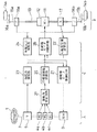
図1に、本実施形態にかかる操舵制御装置の構成を概略的に示す。この操舵制御装置は、運転者が操作するマスタ部A、車輪を操向させるスレーブ部B、及び、マスタ部Aとスレーブ部Bとを電気的に制御する制御部Cで構成される。
【0013】
マスタ部Aは、操舵ハンドル1が取り付けられた操舵軸2と、操舵軸2を回転駆動する操舵軸モータ3とを備えると共に、操舵軸2には、操舵ハンドル1の実操舵角Θを検出するための3つの操舵角センサ4a,4b,4cと、操舵力Tを検出するための操舵力センサ5を設けている。
【0014】
スレーブ部Bは、転舵軸13を変位駆動する際の駆動源となる転舵軸モータ11を備えており、この転舵軸モータ11と転舵軸13との間には、転舵軸モータ11の回転運動を直線運動に変換して転舵軸13を軸方向に変位させる変換器12を設けている。転舵軸13の両端は、それぞれタイロッド15a,15b及びナックルアーム16a,16bを介して操向車輪14a,14bに各々接続されており、転舵軸13が軸方向に沿って変位することで、その変位量及び変位方向に応じて、各操向車輪14a,14bの転舵がなされる機構となっている。タイロッド15a,15bには、左右の操向車輪14a,14bからそれぞれタイロッド15a,15bに付与される軸力(転舵反力)を検出する転舵反力センサ18a,18bが取り付けられている。また、転舵軸13には、この転舵軸13の変位量を検出する転舵変位量センサ17が設けられており、転舵軸13の変位量を転舵変位量センサ17で検出することで、操向車輪14a,14bの実転舵量が検知できる。
【0015】
制御部Cは操舵角判定回路27を備えており、この操舵角判定回路27では、後に詳述するように、3つの操舵角センサ4a,4b,4cでそれぞれ検出された操舵角Θ1、Θ2、Θ3の値をもとに操舵ハンドル1の実操舵角Θを判定している。
【0016】
操舵角判定回路27の判定結果は目標制御量演算器25に与えられ、目標制御量演算器25では、転舵制御、すなわち実操舵角Θに対応するように操向車輪14a,14bを転舵させる際の目標となる目標制御量θが演算される。また、転舵変位量センサ17の検出結果は転舵変位量演算器22に与えられ、転舵変位量演算器22は、この転舵変位量センサ17の検出結果をもとに転舵軸13の変位量を転舵変位量Xとして求めると共に、転舵変位量Xに比例する制御量bX(bは操舵変位ギヤ比に相当する係数)を出力する。目標制御量演算器25で演算された目標制御量θと転舵変位量演算器22で演算された制御量bXとは、ともに転舵軸モータ制御回路26に与えられる。転舵軸モータ制御回路26は、与えられた目標制御量θと制御量bXとをもとに、操向車輪14a,14bの転舵量が目標制御量θとなるように転舵軸モータ11の駆動制御を行う。すなわち、転舵軸13の制御変位量Msを下記の(1)式によって算出し、制御変位量Msに応じた転舵制御信号を転舵軸モータ11に出力する。なお、(1)式中、Gsは転舵制御信号のゲインを示すゲイン係数である。
【0017】
Ms=Gs・(θ−bX) …(1)
一方、操舵ハンドル1に付与された操舵力は操舵力センサ5によって検出され、その検出結果は操舵力演算器23に与えられる。操舵力演算器23は、操舵力センサ5の検出結果をもとに操舵軸2に付与された操舵力Tを演算すると共に、操舵力Tが付与された方向に操舵軸2を回転させるための制御量aT(aは操舵力ギヤ比に相当する係数)に応じた制御量信号を出力する。また、転舵に伴って転舵軸13に付与される転舵反力は転舵反力センサ18a,18bによって検出され、その検出結果は転舵反力演算器24に与えられる。転舵反力演算器24は、転舵反力センサ18a,18bの検出結果をもとに転舵軸13に付与された転舵反力Fを演算する。操舵力演算器23で演算された制御量aTと転舵反力演算器24で演算された転舵反力Fとは、ともに操舵軸モータ制御回路21に与えられる。操舵軸モータ制御回路21は、与えられた制御量aTと転舵反力Fとをもとに、操舵軸モータ3の回転制御量Mmを下記の(2)式によって算出し、回転制御量Mmに応じた反力制御信号を操舵軸モータ3に出力する。なお、(2)式中、Gmは出力信号のゲインを示すゲイン係数である。
【0018】
Mm=Gm・(aT−F) …(2)
ここで、前述した操舵角判定回路27で実施される操舵角の判定処理について、図2のフローチャートをもとに説明する。なお、このフローチャートは、イグニッションスイッチがオンされることで開始され、所定時間毎(例えば、2msec.)に実行される。
【0019】
まず、ステップ100(以下、「ステップ」を「S」と記す)において、3つの操舵角センサ4a,4b,4cでそれぞれ検出された各操舵角Θ1、Θ2、Θ3の値を読み込む。
【0020】
続くS102において、下記に示すように、検出された各操舵角のうち、いずれか2つの操舵角の偏差(絶対値)とその偏差の変化速度(絶対値)との和として求められるV1,V2,V3の値をそれぞれ演算する。
【0021】
V1=|Θ1−Θ2|+|d(Θ1−Θ2)/dt|
V2=|Θ2−Θ3|+|d(Θ2−Θ3)/dt|
V3=|Θ3−Θ1|+|d(Θ3−Θ1)/dt|
上式中、右辺第1項となる偏差の項では、該当する操舵角センサで検出された操舵角がほぼ一致する場合には操舵角の偏差はゼロに近い値となるが、一方の操舵角センサに故障等が発生している場合にはこの偏差はゼロから離れた値を示す。また、右辺第2項となる偏差の変化速度(偏差の微分値)の項を含めることで、第1項の偏差が小さい場合にもその変化速度が大であれば大きな値を示すこととなり、故障等が発生した操舵角センサを早期に判別することができる。例えば、検出値Θ1の値が異常値の場合には、Θ1を含むV1及びV3の値が所定の判定基準値Aよりも大となり、検出値Θ2の値が異常値の場合には、Θ2を含むV1及びV2の値が所定の判定基準値Aよりも大となり、検出値Θ3の値が異常値の場合には、Θ3を含むV2及びV3の値が所定の判定基準値Aよりも大となる。従って、判定基準値Aより大となったVの演算式中に共通に検出結果が含まれる操舵角センサに異常があることが分かる。
【0022】
従って、右辺第1項と第2項との和として演算されるV1,V2又はV3の値が、所定の判定基準値Aより大であれば、判定基準値Aより大となったVの演算式中に共通に含まれる検出結果に異常があることが分かる。
【0023】
そこで、S104、S106、S108において、V1,V2,V3の値を判定基準値Aと比較し、V1,V2,V3の値が全て判定基準値A以下の場合には(S104、S106及びS108で「No」)、S110で全ての操舵角センサ4a,4b,4cが正常に機能していると判別し、S112で舵角演算(Θ1+Θ2+Θ3)/3を行う。その演算結果を操舵ハンドル1の実操舵角Θとして判定し、このルーチンを終了する。
【0024】
また、V2とV3が判定基準値Aより大である場合には(S106で「Yes」、S114で「Yes」)、V2とV3の双方の演算式中に含まれる操舵角Θ3の値に異常があると判別し(S116)、この場合には、S118において舵角演算(Θ1+Θ2)/2を行い、その演算結果を操舵ハンドル1の実操舵角Θとして判定し、このルーチンを終了する。
【0025】
また、V1とV3が判定基準値Aより大である場合には(S104で「Yes」、S120で「No」、S122で「Yes」)、V1とV3の双方の演算式中に含まれる操舵角Θ1の値に異常があると判別し(S124)、この場合には、S126において舵角演算(Θ2+Θ3)/2を行い、その演算結果を操舵ハンドル1の実操舵角Θとして判定し、このルーチンを終了する。
【0026】
また、V1とV2が判定基準値Aより大である場合には(S104で「Yes」、S120で「Yes」、S128で「No」)、V1とV2の双方の演算式中に含まれる操舵角Θ2の値に異常があると判定し(S130)、この場合には、S132において舵角演算(Θ1+Θ3)/2を行い、その演算結果を操舵ハンドル1の実操舵角Θとして判定し、このルーチンを終了する。
【0027】
なお、S108で「Yes」の場合にはV3の演算結果のみが判定基準値Aより大となり、同様にS114で「No」の場合にはV2の演算結果のみが、またS122で「No」の場合にはV1の演算結果のみが、それぞれ判定基準値Aより大となる。前述したように、通常、1つの操舵角センサに異常がある場合には、必ず2つのV演算の結果が判定基準値Aより大となるため、このような場合には、各操舵角センサの検出結果は正常であり、ノイズの影響等により誤演算が行われたものとみなす(S134、S136)。そして、検出された各操舵角の値をもとに舵角演算(Θ1+Θ2+Θ3)/3を行い、その演算結果を操舵ハンドル1の実操舵角Θとして判定する(S112、S138)。
【0028】
また、V1、V2、V3のいずれもが判定基準値Aより大である場合には(S104で「Yes」、S120で「Yes」、S128で「Yes」)、全ての操舵角センサ4a,4b,4cに異常があると判定して(S140)、舵角判定制御を中止し(S142)、予め定められた他の故障対処処理に移行する。
【0029】
以上のような判断処理によって、操舵ハンドル1の実操舵角Θが判定される。
【0030】
ここで、このように構成される操舵制御装置の動作を概略的に説明する。車両が直進している状態から操舵ハンドル1が回転されると、このとき3つの操舵角センサ4a,4b,4cで検出された操舵角Θ1、Θ2、Θ3の値をもとに、操舵角判定回路27において操舵ハンドル1の実操舵角Θが判定される。この実操舵角Θをもとに目標制御量演算器25で目標制御量θが演算されると、式(1)により制御変位量Msが生じ、転舵軸モータ制御回路26からは、制御変位量Msに応じた転舵制御信号が出力される。この転舵制御信号を受けて転舵軸モータ11が作動し、転舵軸13が変位して操向車輪14a,14bが転舵される。この操向車輪14a,14bの実転舵量に対応する転舵変位量Xが転舵変位量演算器22を介して転舵軸モータ制御回路26に与えられ、前出の(1)式に基づいて転舵軸モータ11のフィードバック制御がなされる。そして、θ≒bXとなった時点で転舵軸モータ11の動作が停止する。
【0031】
一方、操向車輪14a、14bが転舵されると転舵反力Fが発生するため、操舵軸モータ制御回路21には、この転舵反力Fを示す信号と操舵力Tに応じた制御量aTとが与えられ、前出の(2)式に基づいて操舵軸モータ3の駆動制御、すなわち操舵軸2に与えられる反力制御がなされる。そして、aT≒Fとなった時点で操舵軸モータ3の動作が停止する。
【0032】
この後、この反力を上回る操舵力Tで操舵ハンドル1を回すと、操舵軸2の回転角が増加するため目標制御量θも増加する。このため、(1)式における制御変位量Msが増加して転舵軸13が変位駆動される。転舵軸13が変位すると転舵反力Fが増大するため、(2)式における回転制御量Mmが変化して、操舵反力が増大するように操舵軸モータ3が再び回転駆動される。この動作の繰り返しにより、操舵ハンドル1の操舵角に対応した操向車輪14a,14bの転舵角が得られると共に、転舵反力に応じた操舵反力が得られる。なお、操舵ハンドル1を戻す際にも同様に、操舵ハンドル1の戻し回転角に対応して操向車輪14a、14bの転舵角が追従すると共に、操舵ハンドル1の操舵力Tも転舵反力Fに対応して減少する。
【0033】
以上説明した実施形態では、図2のS102において、V1等を求める演算式を、2つの操舵角の偏差とその偏差の変化速度との和として例示したが、図3(a)に示すように、V1等を求める演算式を操舵角の偏差の項のみとするか、或いは図3(b)に示すように、操舵角の偏差の変化速度の項のみとしてもよい。
【0034】
また、操舵角センサとして、3つの操舵角センサ4a,4b,4cを備える構成を例示したが、この例に限定するものではなく、少なくとも3つ以上の操舵角センサを備えることで、前述したような舵角判定処理を実施できる。
【0035】
さらに、本実施形態では、転舵変位量センサ17の出力をフィードバックすることにより転舵軸モータ11の駆動制御を行う場合を例示したが、このようなフィードバック制御が行われる場合に限定するものではない。例えば、転舵軸モータ11をステップモータで構成し、このステップモータの回転量を目標制御量θに応じて算出し、この算出結果に基づいてステップモータの回転を制御してもよく、このような場合には、フィードバック制御は不要となる。
【0036】
【発明の効果】
以上説明したように、各請求項にかかる操舵制御装置によれば、第1、第2及び第3の操舵角検出手段によって操舵ハンドルの操舵角をそれぞれ検出すると共に、操舵角判定手段によって、各操舵角検出手段で検出された各操舵角の偏差、各操舵角の偏差の変化速度、或いは各操舵角の偏差とこの偏差の変化速度とをもとに、操舵ハンドルの操舵角を判定するので、いずれかの操舵角センサに故障等が発生した場合にも、転舵制御が困難となる事態を回避し、継続して転舵制御を実施することが可能となる。
【図面の簡単な説明】
【図1】本実施形態にかかる操舵制御装置の構成を示すブロック図である。
【図2】操舵角判定回路で行われる判定処理を示すフローチャートである。
【図3】(a),(b)は、図2で示したフローチャートのうち、S102で行う演算処理の他の実施形態を示す図である。
【図4】従来の操舵制御装置を概略的に示す構成図である。
【符号の説明】
A…マスタ部、B…スレーブ部、C…制御部、1…操舵ハンドル、2…操舵軸、3…操舵軸モータ、4a、4b、4c…操舵角センサ、5…操舵力センサ、11…転舵軸モータ、13…転舵軸、14a,14b…操向車輪(転舵輪)、21…操舵軸モータ制御回路、25…目標制御量演算器、26…転舵軸モータ制御回路、27…操舵角判定回路。[0001]
TECHNICAL FIELD OF THE INVENTION
The present invention relates to a steering control device that steers a steered wheel according to rotation of a steering wheel, and in particular, a steering shaft coupled to the steering wheel and a steering mechanism that steers the steered wheel are mechanically separated, The present invention relates to a steering control device in which these connecting mechanisms are replaced by an electric control device.
[0002]
[Prior art]
FIG. 4 shows an example of a conventional steering control device (JP-A-2-85059). The
[0003]
[Problems to be solved by the invention]
As described above, in the conventional steering control device, since the turning angle of the steered
[0004]
The present invention has been made to solve such a problem, and an object of the present invention is to avoid a situation in which steering control becomes difficult even when a failure or the like occurs in a steering angle sensor, and to continuously perform the steering control. It is an object of the present invention to provide a steering control device capable of performing steering control.
[0007]
[Means for Solving the Problems]
According to a first aspect of the present invention, there is provided a steering control device for turning a steered wheel in conjunction with rotation of a steering wheel, wherein first, second, and third steering angle detections for detecting a steering angle of the steering wheel. Means, a steering angle determining means for determining a steering angle of a steering wheel based on a change speed of a deviation of each steering angle detected by the first, second, and third steering angle detecting means, and a steering angle determining means Target control amount calculating means for calculating a target control amount to be a target of the steering control based on the steering angle determined in the above, steering means mechanically separated from the steering wheel and connected to the steered wheels, And a turning control means for drivingly controlling the turning means so that the turning amount of the steered wheels becomes the target control amount.
[0008]
When the steering angles detected by the first, second, and third steering angle detecting means substantially match, the changing speeds of the deviations of the steering angles detected by the arbitrary two steering angle detecting means also substantially match. . Here, assuming that a failure or the like has occurred in the first steering angle detecting means, the rate of change of the deviation between the steering angles detected by the second and third steering angle detecting means becomes a value close to zero, The rate of change of the deviation of each steering angle detected by the first and second and the first and third sets of steering angle detecting means indicates a value apart from zero. When the rate of change of the deviation of the steering angle indicates a value deviating from zero, the steering angle determination means determines that the steering angle detection means including the detection result in both of the two sets is faulty and remains. The steering angle is determined based on the detection results of the two steering angle detection means. By making a determination based on the rate of change of the deviation, even in a situation where the generated deviation is small, if the rate of change of the deviation is large, it is possible to determine the failure early.
[0009]
According to a second aspect of the present invention, there is provided a steering control device for steering a steered wheel in conjunction with rotation of a steering wheel, wherein first, second, and third steering angle detections for detecting a steering angle of the steering wheel. Means for determining a steering angle of a steering wheel based on deviations of the respective steering angles detected by the first, second, and third steering angle detection means and a change speed of the deviation; A target control amount calculating means for calculating a target control amount serving as a target of the steering control based on the steering angle determined by the steering angle determining means; and a steering wheel mechanically separated from the steering wheel and connected to the steered wheels. The vehicle includes a steering unit and a steering control unit that drives and controls the steering unit so that the steering amount of the steered wheels becomes the target control amount.
[0010]
When the steering angles detected by the first, second, and third steering angle detecting means substantially coincide with each other, the deviation of the steering angles detected by any two of the steering angle detecting means and the rate of change of the deviation are also determined. They almost match. Here, assuming that a failure or the like has occurred in the first steering angle detecting means, the deviation of each steering angle detected by the second and third steering angle detecting means and the rate of change of the deviation are close to zero. The deviation of each steering angle detected by the first and second and first and third sets of steering angle detecting means and the rate of change of the deviation indicate values apart from zero. When the deviation of the steering angle and the rate of change of the deviation indicate values deviating from zero as described above, the steering angle determination means determines that the steering angle detection means including the detection results in both of the two sets is faulty. The steering angle is determined based on the detection results of the remaining two steering angle detecting means. By making a determination based on both the detected deviation of the steering angle and the rate of change of the deviation, the failure can be determined more accurately and earlier.
[0011]
BEST MODE FOR CARRYING OUT THE INVENTION
Hereinafter, embodiments of the present invention will be described with reference to the accompanying drawings.
[0012]
FIG. 1 schematically shows a configuration of a steering control device according to the present embodiment. This steering control device includes a master unit A operated by a driver, a slave unit B for steering wheels, and a control unit C for electrically controlling the master unit A and the slave unit B.
[0013]
The master unit A includes a
[0014]
The slave section B includes a steered
[0015]
The control unit C includes a steering
[0016]
The result of the determination by the steering
[0017]
Ms = Gs · (θ−bX) (1)
On the other hand, the steering force applied to the steering wheel 1 is detected by the steering
[0018]
Mm = Gm · (aT−F) (2)
Here, the steering angle determination processing performed by the steering
[0019]
First, in step 100 (hereinafter, “step” is described as “S”), the values of the steering angles Θ1, Θ2, and Θ3 detected by the three
[0020]
In S102, as described below, V1 and V2 obtained as the sum of the deviation (absolute value) of any two of the detected steering angles and the change speed (absolute value) of the deviation. , V3 are calculated.
[0021]
V1 = | Θ1-Θ2 | + | d (Θ1-Θ2) / dt |
V2 = | Θ2-Θ3 | + | d (Θ2-Θ3) / dt |
V3 = | Θ3-Θ1 | + | d (Θ3-Θ1) / dt |
In the above equation, in the deviation term that is the first term on the right side, when the steering angles detected by the corresponding steering angle sensors substantially match, the deviation of the steering angle becomes a value close to zero. If a failure or the like has occurred in the sensor, this deviation indicates a value away from zero. Also, by including the term of the change rate of the deviation (differential value of the deviation), which is the second term on the right side, even if the deviation of the first term is small, if the change rate is large, the value shows a large value, The steering angle sensor in which a failure or the like has occurred can be determined early. For example, when the value of the detection value 異常 1 is an abnormal value, the values of V1 and V3 including Θ1 are larger than a predetermined determination reference value A, and when the value of the detection value Θ2 is an abnormal value, Θ2 is set. If the values of V1 and V2 that include V3 and V2 are greater than the predetermined determination reference value A and the value of the detection value Θ3 is an abnormal value, the values of V2 and V3 that include Θ3 are greater than the predetermined determination reference value A. Become. Therefore, it is understood that the steering angle sensor whose detection result is commonly included in the arithmetic expression of V that has become larger than the determination reference value A has an abnormality.
[0022]
Therefore, if the value of V1, V2 or V3 calculated as the sum of the first term and the second term on the right side is larger than the predetermined criterion value A, the calculation of V larger than the criterion value A is performed. It can be seen that there is an abnormality in the detection result commonly included in the expression.
[0023]
Therefore, in S104, S106, and S108, the values of V1, V2, and V3 are compared with the criterion value A. (No)), it is determined in S110 that all the
[0024]
When V2 and V3 are larger than the determination reference value A (“Yes” in S106 and “Yes” in S114), the value of the steering angle Θ3 included in both the arithmetic expressions of V2 and V3 is abnormal. Is determined (S116), in this case, the steering angle calculation (Θ1 + Θ2) / 2 is performed in S118, the calculation result is determined as the actual steering angle の of the steering wheel 1, and the routine ends.
[0025]
If V1 and V3 are larger than the determination reference value A (“Yes” in S104, “No” in S120, “Yes” in S122), the steering included in both the arithmetic expressions of V1 and V3 is performed. It is determined that the value of the angle Θ1 is abnormal (S124). In this case, the steering angle calculation (Θ2 + Θ3) / 2 is performed in S126, and the calculation result is determined as the actual steering angle の of the steering wheel 1. End the routine.
[0026]
When V1 and V2 are larger than the determination reference value A (“Yes” in S104, “Yes” in S120, and “No” in S128), the steering included in both the arithmetic expressions of V1 and V2 is performed. It is determined that the value of the angle Θ2 is abnormal (S130). In this case, the steering angle calculation (Θ1 + Θ3) / 2 is performed in S132, and the calculation result is determined as the actual steering angle の of the steering wheel 1. End the routine.
[0027]
In the case of "Yes" in S108, only the calculation result of V3 is larger than the determination reference value A. Similarly, in the case of "No" in S114, only the calculation result of V2 is obtained. In this case, only the calculation result of V1 is larger than the determination reference value A. As described above, normally, when one steering angle sensor is abnormal, the result of the two V calculations always becomes larger than the determination reference value A. It is assumed that the detection result is normal and that an erroneous calculation has been performed due to the influence of noise or the like (S134, S136). Then, a steering angle calculation (Θ1 + Θ2 + Θ3) / 3 is performed based on the detected values of the steering angles, and the calculation result is determined as the actual steering angle の of the steering wheel 1 (S112, S138).
[0028]
When all of V1, V2, and V3 are larger than the determination reference value A (“Yes” in S104, “Yes” in S120, and “Yes” in S128), all the
[0029]
Through the above-described determination processing, the actual steering angle の of the steering wheel 1 is determined.
[0030]
Here, the operation of the steering control device thus configured will be schematically described. When the steering wheel 1 is rotated while the vehicle is traveling straight, the steering angle determination is performed based on the values of the steering angles Θ1, Θ2, and Θ3 detected by the three
[0031]
On the other hand, when the steered
[0032]
Thereafter, when the steering wheel 1 is turned with the steering force T exceeding this reaction force, the target control amount θ also increases because the rotation angle of the
[0033]
In the embodiment described above, in S102 of FIG. 2, the calculation formula for obtaining V1 and the like is exemplified as the sum of the deviation of the two steering angles and the change speed of the deviation, but as shown in FIG. , V1 or the like may be made only the term of the deviation of the steering angle or, as shown in FIG. 3B, only the term of the change speed of the deviation of the steering angle.
[0034]
In addition, the configuration including three
[0035]
Further, in the present embodiment, the case where the drive control of the steered
[0036]
【The invention's effect】
As described above, according to the steering control device according to each claim, the first, second, and third steering angle detecting means respectively detect the steering angle of the steering wheel, and the steering angle determining means determines The steering angle of the steering wheel is determined based on the deviation of each steering angle detected by the steering angle detecting means, the changing speed of the deviation of each steering angle, or the deviation of each steering angle and the changing speed of this deviation. Also, even when a failure or the like occurs in any of the steering angle sensors, it is possible to avoid a situation in which the steering control becomes difficult, and to continuously perform the steering control.
[Brief description of the drawings]
FIG. 1 is a block diagram illustrating a configuration of a steering control device according to an embodiment.
FIG. 2 is a flowchart illustrating a determination process performed by a steering angle determination circuit.
FIGS. 3A and 3B are diagrams showing another embodiment of the arithmetic processing performed in S102 in the flowchart shown in FIG. 2;
FIG. 4 is a configuration diagram schematically showing a conventional steering control device.
[Explanation of symbols]
A: Master unit, B: Slave unit, C: Control unit, 1: Steering handle, 2: Steering shaft, 3: Steering shaft motor, 4a, 4b, 4c: Steering angle sensor, 5: Steering force sensor, 11: Rolling Rudder shaft motor, 13: steered shaft, 14a, 14b: steered wheel (steered wheel), 21: steered shaft motor control circuit, 25: target control amount calculator, 26: steered shaft motor control circuit, 27: steering Angle determination circuit.
Claims (2)
前記操舵ハンドルの操舵角を検出する第1、第2及び第3の操舵角検出手段と、前記第1、第2及び第3の操舵角検出手段で検出された各操舵角の偏差の変化速度をもとに前記操舵ハンドルの操舵角を判定する操舵角判定手段と、前記操舵角判定手段で判定された操舵角をもとに転舵制御の目標となる目標制御量を演算する目標制御量演算手段と、前記操舵ハンドルと機械的に分離され、転舵輪に連結された転舵手段と、前記転舵輪の転舵量が前記目標制御量となるように前記転舵手段を駆動制御する転舵制御手段とを備える操舵制御装置。In a steering control device that turns a steered wheel in conjunction with rotation of a steering handle,
First, second, and third steering angle detecting means for detecting a steering angle of the steering wheel; and a changing speed of a deviation of each steering angle detected by the first, second, and third steering angle detecting means. Steering angle determining means for determining a steering angle of the steering wheel based on the steering angle; and a target control amount for calculating a target control amount to be a target of turning control based on the steering angle determined by the steering angle determining means. A calculating means, a turning means mechanically separated from the steering wheel and connected to the steered wheels, and a turning means for controlling the turning of the steered means so that the steered amount of the steered wheels becomes the target control amount. A steering control device comprising: a rudder control unit.
前記操舵ハンドルの操舵角を検出する第1、第2及び第3の操舵角検出手段と、前記第1、第2及び第3の操舵角検出手段で検出された各操舵角の偏差とこの偏差の変化速度とをもとに前記操舵ハンドルの操舵角を判定する操舵角判定手段と、前記操舵角判定手段で判定された操舵角をもとに転舵制御の目標となる目標制御量を演算する目標制御量演算手段と、前記操舵ハンドルと機械的に分離され、転舵輪に連結された転舵手段と、前記転舵輪の転舵量が前記目標制御量となるように前記転舵手段を駆動制御する転舵制御手段とを備える操舵制御装置。In a steering control device that turns a steered wheel in conjunction with rotation of a steering handle,
First, second and third steering angle detecting means for detecting a steering angle of the steering wheel; deviations of the respective steering angles detected by the first, second and third steering angle detecting means; A steering angle determining means for determining a steering angle of the steering wheel based on the change speed of the steering wheel; and a target control amount serving as a target of the turning control based on the steering angle determined by the steering angle determining means. Target control amount calculating means, mechanically separated from the steering wheel, turning means connected to steered wheels, and turning means so that the steered amount of the steered wheels becomes the target control amount. A steering control device comprising: a steering control unit that performs drive control.
Priority Applications (1)
| Application Number | Priority Date | Filing Date | Title |
|---|---|---|---|
| JP6662597A JP3577190B2 (en) | 1997-03-19 | 1997-03-19 | Steering control device |
Applications Claiming Priority (1)
| Application Number | Priority Date | Filing Date | Title |
|---|---|---|---|
| JP6662597A JP3577190B2 (en) | 1997-03-19 | 1997-03-19 | Steering control device |
Publications (2)
| Publication Number | Publication Date |
|---|---|
| JPH10258757A JPH10258757A (en) | 1998-09-29 |
| JP3577190B2 true JP3577190B2 (en) | 2004-10-13 |
Family
ID=13321270
Family Applications (1)
| Application Number | Title | Priority Date | Filing Date |
|---|---|---|---|
| JP6662597A Expired - Fee Related JP3577190B2 (en) | 1997-03-19 | 1997-03-19 | Steering control device |
Country Status (1)
| Country | Link |
|---|---|
| JP (1) | JP3577190B2 (en) |
Cited By (1)
| Publication number | Priority date | Publication date | Assignee | Title |
|---|---|---|---|---|
| EP3196096A4 (en) * | 2014-09-17 | 2018-04-18 | NSK Ltd. | Electric power steering device |
Families Citing this family (6)
| Publication number | Priority date | Publication date | Assignee | Title |
|---|---|---|---|---|
| JP3784248B2 (en) * | 2000-10-02 | 2006-06-07 | 株式会社ジェイテクト | Rotation angle detection device, torque sensor and steering device |
| FR2832685A1 (en) * | 2001-11-23 | 2003-05-30 | Conception & Dev Michelin Sa | ELECTRIC STEERING FOR VEHICLE, TRIPLE REDUNDANCY |
| JP2006335252A (en) | 2005-06-02 | 2006-12-14 | Jtekt Corp | Electric power steering device |
| JP5227211B2 (en) * | 2009-02-06 | 2013-07-03 | 本田技研工業株式会社 | Electric power steering device |
| CN102706271A (en) * | 2012-05-31 | 2012-10-03 | 西北工业大学 | Redundancy device for angle position sensors of control plane of steering engine and control method for device |
| KR101724902B1 (en) | 2015-09-15 | 2017-04-07 | 현대자동차주식회사 | Integrated power steering system for front wheel-rear wheel of vehicle and control method thereof |
-
1997
- 1997-03-19 JP JP6662597A patent/JP3577190B2/en not_active Expired - Fee Related
Cited By (1)
| Publication number | Priority date | Publication date | Assignee | Title |
|---|---|---|---|---|
| EP3196096A4 (en) * | 2014-09-17 | 2018-04-18 | NSK Ltd. | Electric power steering device |
Also Published As
| Publication number | Publication date |
|---|---|
| JPH10258757A (en) | 1998-09-29 |
Similar Documents
| Publication | Publication Date | Title |
|---|---|---|
| US7520367B2 (en) | Vehicle steering apparatus | |
| US8504243B2 (en) | Vehicular steering apparatus and control method thereof | |
| US5065325A (en) | Device for determining malfunctioning of electric-motor-assisted power steering system of motor vehicle | |
| US6079513A (en) | Steering apparatus for vehicle | |
| EP2019020B1 (en) | Power steering apparatus having failure detection device for rotation angle sensors | |
| JPH0438419A (en) | Steering angle detector | |
| KR102546961B1 (en) | Apparatus of steer by wire | |
| JP3577190B2 (en) | Steering control device | |
| JP3564696B2 (en) | Vehicle steering control device | |
| JP2007071784A (en) | Torque sensing device | |
| JP5011785B2 (en) | Electric power steering device | |
| JP3755273B2 (en) | Steering control device | |
| JPH10217988A (en) | Steering controller | |
| JP3605885B2 (en) | Automatic vehicle steering system | |
| JPH0285059A (en) | Moter-driven power steering device | |
| JP3741039B2 (en) | Steering control device | |
| JP2004224234A (en) | Steering gear for vehicle | |
| JP2013126792A (en) | Vehicle steering device | |
| JPH10264833A (en) | Steering controller | |
| JPH0443171A (en) | Rear wheel steering mechanism for vehicle | |
| JPH10258750A (en) | Steering controller | |
| JP5282870B2 (en) | Wheel turning device and turning actuator neutral position return method | |
| JPH07329808A (en) | Abnormality detecting device for steering control device | |
| JP3885618B2 (en) | Vehicle steering device | |
| JPH06263048A (en) | Abnormality detector for rear wheel steering |
Legal Events
| Date | Code | Title | Description |
|---|---|---|---|
| A977 | Report on retrieval |
Free format text: JAPANESE INTERMEDIATE CODE: A971007 Effective date: 20040216 |
|
| A131 | Notification of reasons for refusal |
Free format text: JAPANESE INTERMEDIATE CODE: A131 Effective date: 20040419 |
|
| A521 | Written amendment |
Free format text: JAPANESE INTERMEDIATE CODE: A523 Effective date: 20040608 |
|
| TRDD | Decision of grant or rejection written | ||
| A01 | Written decision to grant a patent or to grant a registration (utility model) |
Free format text: JAPANESE INTERMEDIATE CODE: A01 Effective date: 20040630 |
|
| A61 | First payment of annual fees (during grant procedure) |
Free format text: JAPANESE INTERMEDIATE CODE: A61 Effective date: 20040709 |
|
| R150 | Certificate of patent or registration of utility model |
Free format text: JAPANESE INTERMEDIATE CODE: R150 |
|
| S533 | Written request for registration of change of name |
Free format text: JAPANESE INTERMEDIATE CODE: R313533 |
|
| R350 | Written notification of registration of transfer |
Free format text: JAPANESE INTERMEDIATE CODE: R350 |
|
| FPAY | Renewal fee payment (event date is renewal date of database) |
Free format text: PAYMENT UNTIL: 20080716 Year of fee payment: 4 |
|
| FPAY | Renewal fee payment (event date is renewal date of database) |
Free format text: PAYMENT UNTIL: 20080716 Year of fee payment: 4 |
|
| FPAY | Renewal fee payment (event date is renewal date of database) |
Free format text: PAYMENT UNTIL: 20090716 Year of fee payment: 5 |
|
| FPAY | Renewal fee payment (event date is renewal date of database) |
Free format text: PAYMENT UNTIL: 20090716 Year of fee payment: 5 |
|
| FPAY | Renewal fee payment (event date is renewal date of database) |
Free format text: PAYMENT UNTIL: 20100716 Year of fee payment: 6 |
|
| FPAY | Renewal fee payment (event date is renewal date of database) |
Free format text: PAYMENT UNTIL: 20110716 Year of fee payment: 7 |
|
| FPAY | Renewal fee payment (event date is renewal date of database) |
Free format text: PAYMENT UNTIL: 20110716 Year of fee payment: 7 |
|
| FPAY | Renewal fee payment (event date is renewal date of database) |
Free format text: PAYMENT UNTIL: 20120716 Year of fee payment: 8 |
|
| FPAY | Renewal fee payment (event date is renewal date of database) |
Free format text: PAYMENT UNTIL: 20120716 Year of fee payment: 8 |
|
| FPAY | Renewal fee payment (event date is renewal date of database) |
Free format text: PAYMENT UNTIL: 20130716 Year of fee payment: 9 |
|
| R250 | Receipt of annual fees |
Free format text: JAPANESE INTERMEDIATE CODE: R250 |
|
| LAPS | Cancellation because of no payment of annual fees |