JP3636460B2 - Method and system for detecting and generating transients in acoustic signals - Google Patents
Method and system for detecting and generating transients in acoustic signals Download PDFInfo
- Publication number
- JP3636460B2 JP3636460B2 JP52376294A JP52376294A JP3636460B2 JP 3636460 B2 JP3636460 B2 JP 3636460B2 JP 52376294 A JP52376294 A JP 52376294A JP 52376294 A JP52376294 A JP 52376294A JP 3636460 B2 JP3636460 B2 JP 3636460B2
- Authority
- JP
- Japan
- Prior art keywords
- transient
- signal
- shape
- envelope
- leading edge
- Prior art date
- Legal status (The legal status is an assumption and is not a legal conclusion. Google has not performed a legal analysis and makes no representation as to the accuracy of the status listed.)
- Expired - Fee Related
Links
- 238000000034 method Methods 0.000 title claims abstract description 70
- 230000001052 transient effect Effects 0.000 claims abstract description 161
- 238000001514 detection method Methods 0.000 claims abstract description 29
- 230000008859 change Effects 0.000 claims abstract description 24
- 241000282414 Homo sapiens Species 0.000 claims abstract description 22
- 238000001914 filtration Methods 0.000 claims description 11
- 238000005259 measurement Methods 0.000 claims description 8
- 241001465754 Metazoa Species 0.000 claims description 5
- 230000006835 compression Effects 0.000 claims description 4
- 238000007906 compression Methods 0.000 claims description 4
- 238000000605 extraction Methods 0.000 claims description 2
- 238000012545 processing Methods 0.000 abstract description 11
- 230000015572 biosynthetic process Effects 0.000 abstract description 7
- 238000003786 synthesis reaction Methods 0.000 abstract description 7
- 230000014759 maintenance of location Effects 0.000 abstract 1
- 230000004044 response Effects 0.000 description 34
- 238000004458 analytical method Methods 0.000 description 31
- 238000010586 diagram Methods 0.000 description 22
- 210000003477 cochlea Anatomy 0.000 description 13
- 238000001228 spectrum Methods 0.000 description 13
- 238000002474 experimental method Methods 0.000 description 10
- 238000007781 pre-processing Methods 0.000 description 10
- 230000005236 sound signal Effects 0.000 description 8
- 230000035945 sensitivity Effects 0.000 description 6
- 238000005070 sampling Methods 0.000 description 5
- 238000010183 spectrum analysis Methods 0.000 description 5
- 238000004891 communication Methods 0.000 description 4
- 230000006870 function Effects 0.000 description 4
- 210000005036 nerve Anatomy 0.000 description 4
- 230000008447 perception Effects 0.000 description 4
- 238000003672 processing method Methods 0.000 description 4
- 230000008569 process Effects 0.000 description 3
- 230000009466 transformation Effects 0.000 description 3
- 101100272680 Paracentrotus lividus BP10 gene Proteins 0.000 description 2
- 230000006837 decompression Effects 0.000 description 2
- 238000013461 design Methods 0.000 description 2
- 210000005069 ears Anatomy 0.000 description 2
- 230000000737 periodic effect Effects 0.000 description 2
- 238000013441 quality evaluation Methods 0.000 description 2
- 230000035939 shock Effects 0.000 description 2
- 230000001360 synchronised effect Effects 0.000 description 2
- 241000282412 Homo Species 0.000 description 1
- 238000013459 approach Methods 0.000 description 1
- 230000005540 biological transmission Effects 0.000 description 1
- 210000004556 brain Anatomy 0.000 description 1
- 238000006243 chemical reaction Methods 0.000 description 1
- 210000000860 cochlear nerve Anatomy 0.000 description 1
- 230000000295 complement effect Effects 0.000 description 1
- 230000001186 cumulative effect Effects 0.000 description 1
- 239000006185 dispersion Substances 0.000 description 1
- 230000000694 effects Effects 0.000 description 1
- 230000005284 excitation Effects 0.000 description 1
- 238000005562 fading Methods 0.000 description 1
- 238000009532 heart rate measurement Methods 0.000 description 1
- 239000000203 mixture Substances 0.000 description 1
- 238000003909 pattern recognition Methods 0.000 description 1
- 238000002360 preparation method Methods 0.000 description 1
- 230000033764 rhythmic process Effects 0.000 description 1
- 230000011218 segmentation Effects 0.000 description 1
- 230000035807 sensation Effects 0.000 description 1
- 238000000926 separation method Methods 0.000 description 1
- 239000007787 solid Substances 0.000 description 1
- 230000003595 spectral effect Effects 0.000 description 1
- 230000001629 suppression Effects 0.000 description 1
- 230000002194 synthesizing effect Effects 0.000 description 1
- 230000002123 temporal effect Effects 0.000 description 1
- 238000012360 testing method Methods 0.000 description 1
- 230000000007 visual effect Effects 0.000 description 1
Images


Classifications
-
- G—PHYSICS
- G10—MUSICAL INSTRUMENTS; ACOUSTICS
- G10L—SPEECH ANALYSIS TECHNIQUES OR SPEECH SYNTHESIS; SPEECH RECOGNITION; SPEECH OR VOICE PROCESSING TECHNIQUES; SPEECH OR AUDIO CODING OR DECODING
- G10L25/00—Speech or voice analysis techniques not restricted to a single one of groups G10L15/00 - G10L21/00
- G10L25/48—Speech or voice analysis techniques not restricted to a single one of groups G10L15/00 - G10L21/00 specially adapted for particular use
-
- G—PHYSICS
- G10—MUSICAL INSTRUMENTS; ACOUSTICS
- G10L—SPEECH ANALYSIS TECHNIQUES OR SPEECH SYNTHESIS; SPEECH RECOGNITION; SPEECH OR VOICE PROCESSING TECHNIQUES; SPEECH OR AUDIO CODING OR DECODING
- G10L15/00—Speech recognition
- G10L15/02—Feature extraction for speech recognition; Selection of recognition unit
Landscapes
- Engineering & Computer Science (AREA)
- Multimedia (AREA)
- Acoustics & Sound (AREA)
- Health & Medical Sciences (AREA)
- Audiology, Speech & Language Pathology (AREA)
- Human Computer Interaction (AREA)
- Physics & Mathematics (AREA)
- Computational Linguistics (AREA)
- Computer Vision & Pattern Recognition (AREA)
- Signal Processing (AREA)
- Measurement Of Mechanical Vibrations Or Ultrasonic Waves (AREA)
- Electrophonic Musical Instruments (AREA)
- Monitoring And Testing Of Nuclear Reactors (AREA)
- Telephone Function (AREA)
- Examining Or Testing Airtightness (AREA)
- Investigating, Analyzing Materials By Fluorescence Or Luminescence (AREA)
Abstract
Description
本発明は信号処理のための方法とシステムに関し、その方法とシステムによって音響信号中の識別可能な音響像をあらわす特徴が音響信号中の過渡成分から抽出される。この処理の結果は、音または話声信号の識別、またはラウドスピーカーや補聴器や遠距離通信システムなどの音響製品またはシステムの品質評価または、音響条件の品質評価に用いられる。本発明の方法はまた、狭帯域遠距離通信における話声の圧縮および復元に関連して用いることができる。
先行技術の音響信号の信号解析の方法においては、信号はある短時間のあいだ定常状態であると考えられ、短時間スペクトル解析の形がこの仮定のもとで用いられている。
ヒトの耳は、同時に速い音声信号をとらえ、高い精度で音声周波数を検知し、複雑な音声環境で音声信号を区別する能力を持っている。たとえば、音楽楽器の伴奏のもとで歌手が歌っている内容を理解することができる。
先行技術の信号解析の方法および本発明の方法では、ヒトの耳中の蝸牛は、ヒトの耳の周波数範囲において無数の帯域通過濾波器(バンドパスフィルタ)、IBPとみなし得ると仮定される。
励起による1つの帯域通過濾波器の時間応答f(t)は、過渡応答ft(t)と定常状態応答fs(t)の2つの成分に分離することができる。
(1)f(t)=ft(t)+fs(t)
伝統的な信号処理は定常状態応答fs(t)に基づいており、過渡応答ft(t)は非常に速く消え去り、知覚にとって重要ではないと仮定され、たとえば「回路合成の原理」(マグローヒル、1959、エルネスト5.クーおよびドナルド オー.ペデルセン、12頁、9〜15を参照すると、そこには「強制応答のみが考慮され、回路網(network)の初期状態に起因する応答は無視される。」と述べられている。
このように、学生が信号解析の世界に案内される時、過渡応答すなわち回路網の初期状態による応答は、非常に短い時間で消え去るので無視すべきであると、非常に初期の段階で彼らは学ぶ。さらに、伝統的な線形解析法を用いてこれらの過渡信号を解析することはなかなかむずかしい。
ヒトが、非常に短い音を聞き、同時に高い精度で周波数を検出する能力は、伝統的な濾波器ベースのスペクトル解析と矛盾する。帯域通過濾波器の時間窓(time window)(立ち上がり時間の2倍)は帯域幅に逆比例する。
(2)tw=2/(fuーfl)
ここでf1は下側遮断周波数(cutoff frequency)で、fuは上側遮断周波数である。
このようにもし5msの立ち上がり時間が要求されるとき、結果としては、周波数分解能が400Hz以下である。
これらの過渡成分の検知が、高周波数分解能と矛盾するので、ヒトの耳によるこれらの過渡成分の検知は、他の方法でなされるに違いない。ヒトの耳がこれらの信号をどのように検出することができるのかはまだ調べられていないが、蝸牛は音を受信していないとき静止の位置にあり、そこでは蝸牛は非常に広帯域であろう。音声信号が受信されると、蝸牛はその信号中の周波数成分に固定され始める。このように、蝸牛は開始時点では広帯域であるが、もし1つ以上の安定な周波数が受信されると、蝸牛は高い精度でこの周波数に固定される。
蝸牛から発生した神経パルスは周波数が約1.4kHz未満の時、音調の周波数に同期することが今日知られている。もし周波数が1.4kHzより大きい時、パルスはその周波数1のサイクルあたり1未満の回数でランダムに生成される。
濾波器バンクスペクトル解析に基づく信号解析が英国特許第2213623号に開示されており、それは、音素認識のためのシステムを記述している。このシステムは音声信号の過渡的部分を検出する検出手段をそなえており、そこにおける過渡検出の主要な目的は話声スペクトルが最も鋭く変化する点すなわちピーク点を検出することである。ピーク点の検出はより正確な音素分割のために用いられる。
英国特許第2213623号の過渡解析は、スペクトル解析およびスペクトル変化に基づいており、時間領域における直接の過渡検出に基づいた、本発明の過渡解析とは相当異なっている。
本発明は、音響信号の解析のための知られているすべての方法と原理的に異なるアプローチに基づいている。音響信号の同定に関連する信号情報が信号の過渡成分に存在していることが、本発明により見出された。このように本発明の方法は、過渡成分の分離または音響信号の応答と、過渡成分に対応する過渡パルスの生成と、パルスの形状の解析を含む。音響信号において、対応する過渡パルスは時間間隔をおいて繰り返され、これらの周期的過渡パルスの時間間隔がふつうまた解析あるいは決定される。
実生活の場で、ヒトの耳は音素あるいは音響像を認識するため高周波数でのエネルギー変化に反応する。しかし本方法では、耳によって観察されるエネルギー変化に対応する過渡パルスはこれらの高周波数において抽出され、その後過渡パルスは音響像または音素の個々の特性を保ちながら、低周波数範囲に変換されることが望ましい。このように本発明の原理を用いて、変換された低周波数信号を調べることにより音響信号中の個々の特性を得ることができる。
以下に述べる本発明の方法の説明から理解されるように、パルスの過渡波形あるいは形状を抽出する概念は、現在使われている最良の設計よりずっと簡単な前処理方法を用い、かつ同時に、音響入力信号に関してずっと価値のある情報を得ることを可能にする。
本発明は、その最も広い観点によれば、識別可能な音響像を表すものとして、ヒトの耳などの動物の耳により知覚され得る特徴を同定あるいは表現するための、音響信号のエネルギー変化の形状の利用に関する。
本発明の方法の特色のより詳細な説明にはいる前に、いくつかの定義が与えられる。
短時間解析において、信号における過渡成分は定義の対象である。その発想は信号エネルギーの急激な変化に対する蝸牛における応答に対応する応答を与える表現を得ることにある。信号エネルギーにおける急激な変化は、音響信号における過渡成分に対応する。そこで、この文脈では、「過渡成分」という用語は、音響信号における急激なエネルギー変化に対応する何らかの信号を表す。過渡成分は解析されるべき信号情報を保持しており、この情報を解析するため過渡成分は異なる形状をもつ対応過渡パルスに変換できる。そこでこの明細書では、「過渡パルス」という用語は、識別可能な形状を持ち、実質的に音響信号の過渡成分の情報を保持し、それにより音響信号のエネルギーにおける急激な変化に対応するパルスを意味する。上述のように音響信号の過渡部分は時間間隔をおいて繰り返される。そこで、この明細書では、「周期的」という用語は過渡成分、応答、またはパルスと組み合わせて用いられるときには、間隔をおいて繰り返される何らかの過渡成分、応答またはパルスを表す。
「形状」という用語は、与えられた時間隔区間Tpの中で、その区間外の振幅レベルと比べてはっきり異なった振幅レベルをもつ、(時間限定されたまたは時間限定されていない)、何らかの時間的に変化する任意の関数を表す。このように、Tpは、形状関数が時間限定されているときはその形状関数の継続時間であり、そうでない時は、その時区間外の振幅レベルに比べてはっきり異なった振幅レベルを持つ関数部分の継続時間である。理解されるように、パルスの形状の同定はパルスの時間軸にそったパルスの振幅を観察することにより、適切に行われる。
エネルギー変化の形状から情報を抽出するために、本発明の1つの広い観点は、信号の過渡パルスの形状によってエネルギー変化の形状を表すことに関連する。しかしながら、エネルギー変化に対応する過渡パルスを得るためにいくつかの方法を適用することができるが、包絡線(envelope)検出法が用いられることが望ましく、その際包絡線は音響信号のエネルギー変化の過渡応答から検出されることが望ましい。
異なる音響像を表すエネルギー変化は、音響信号における急激なエネルギー変化を与える音素あるいは母音その他の音であることが可能である。
また、本発明のある観点によれば、信号のエネルギー変化の形状を、識別可能な音響像を表す予め設定されたエネルギー変化形状と比較することからなり、かつ識別可能な音響像を表すものとしてヒトの耳などの動物の耳に知覚されることのできるエネルギー変化を、音響信号中で同定するための方法が提供される。同定のためには、エネルギー変化の形状が信号の過渡パルスの形状によって表されることが望ましく、さらに過渡パルスの形状が、音響信号におけるエネルギー変化の過渡応答の包絡線検出によって得られることが望ましい。
またこの発明は、音響信号の過渡成分を抽出することと、過渡成分の包絡線を検出することを含む、信号の情報を実質的に保持しながら信号の帯域を減らすために音響信号を処理する方法に関する。異なる音響像を表すものとして、ヒトの耳などの動物の耳に知覚され得る信号の過渡パルス形状が同定されることが望ましい。
パルス立ち上がり時間あるいは先導エッジの形、パルスの継続時間および立ち下がり時間あるいは衰微エッジの形はすべて、パルスの同定のための重要な特性であることに注目するべきである。発明の好ましい実施態様によれば、パルスの先導エッジの形が同定され、さらに先導エッジの形の少なくとも一部の立ち上がり時間と勾配及び/又は勾配変動を決定することにより先導エッジの形が決定されることが望ましい。
発明の好ましい実施態様によれば、パルスの上方部分が必要な情報を含んでいるので、先導エッジの形の少なくとも頂上部分の立ち上がり時間と勾配及び/又は勾配変動が測定される。頂上部分は、勾配が最大になる点から実質的に始まる部分と定義してよい。頂上部分はまた、パルスの振幅の上方の50%に対応する部分でもよい。
パルスの形状を決定するときに、いくつかの方法が用いられるが、望ましい実施態様においては、先導エッジの立ち上がり時間と勾配及び/又は勾配変動が少なくとも5つの試料を基として測定される。しかしながら試料の数は他の適当な数であってもよい。また別の、先導エッジの形状の同定の望ましい方法は、参照ライブラリとの比較を用いて実行される。ここで、比較する際の参照物は先導エッジの立ち上がり時間を基にして選ぶことができる。
また、パルスの継続時間の同定が行われることが望ましい。ここでパルスの継続時間は、所定の振幅における先導エッジから衰微エッジまでの距離として定められる。
また、了解されることであるが、過渡パルスの衰微エッジの形状を同定することが望ましい。
本発明の方法は、音響信号の過渡状態の表現を提供する。その方法は、ヒトの耳の周波数範囲にある音響信号の帯域通過濾波(filtration)と低域通過濾波した包絡線の検出を含む。包絡線は、その後公知の信号解析の方法で解析することができる。包絡線は信号の過渡部分の表現である。
包絡線解析に用いるべき公知の信号解析方法および選択すべき帯域通過濾波器の特性は、解析の目的に依存する。その目的は、話声認識、オーディオ製品や音響条件の品質測定、狭帯域遠距離通信などである。
本発明はまた、音響信号の過渡成分を抽出する手段と、過渡成分の包絡線を検出する手段を備えており、信号の情報を実質的に保持しつつ信号の帯域幅を縮小するための音響信号処理システムに関する。
実施例とシステムの詳細は、図面とそのシステムの実施例の数学的記述に関してなされるシステムの実施例の詳細な議論と、請求項から明らかになる。
以下、本発明をその原理の数学的記述および図面に関連して、さらに詳細に記述する。
図1は、帯域通過濾波器F(ω)と低域通過濾波器H(ω)のスペクトルを示す図である。
図2は、同一の帯域幅をもつ無数の帯域通過濾波器IBPに対する、s−平面における零(zeros)および極(poles)を示す図である。
図3は、同一のQ値をもつ無数の帯域通過濾波器IBPに対する、s−平面における零および極を示す図である。
図4は、s−平面における種々の根部位(root locations)に対する衝撃応答(impulse response)を示す図である。
図5は「linear prediction」という言葉に対するスペクトログラムを示す図である。
図6は、無数の帯域通過濾波器IBPの和が、1回の帯域濾波によってなされるかを示す図である。
図7は、本発明による過渡検出システムの原理を示す図である。
図8は、本発明による過渡検出システムのブロックダイアグラムを示す図である。
図9は、図8のシステムにおいて用いるべき望ましい高域通過濾波器の特性を示す図である。
図10は、図8のシステムにおいて用いるべき望ましい低域通過濾波器の特性を示す図である。
図11は、ヒトの耳の感度を示す図である。
図12は、アメリカ母音の/i(:)/
![]()
図13は、図11の母音の第一過渡解析の実験結果を示す図である。
図14は、「heat」における母音「i」の処理後の曲線を示す図である。
図15は、「hop」における母音「o」に対する、図12と同様の曲線を示す図である。
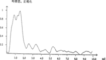
図16は、「heat」における母音「i」の処理後の曲線に対する、正規化した時間窓を示す図である。
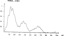
図17は、「hop」における母音「o」に対する、正規化した時間窓を示す図である。
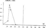
図18は、「have」における母音「a」に対する、正規化した時間窓を示す図である。
図19は、本発明による話声認識システムのブロックダイアグラムを示す図である。
図20から25は、それぞれ「heat」における音素「i」、「hop」における「o」、「ongaonga」における「o」、デンマーク語の単語「hus」における「u」、デンマーク語の単語「φse」における「φ」、デンマーク語の単語「lys」における「y」の話声合成のための過渡パルスを示す図である。
まず、本発明の原理の数学的説明が与えられる。
帯域通過濾波器は、時間領域において衝撃応答(インパルスレスポンス)により表され、次の式で表現される。
f(t)=h(t)cos(ωct)
ここでh(t)は低域通過濾波器に対する衝撃応答であり、ωcは帯域通過濾波器f(t)の中心周波数である。cos(ωct)の項は、中心周波数がωcの帯域通過濾波器への低域通過濾波器の周波数偏移(shift)を表すものとみなされる。
このことは図1に示され、f(ω)およびH(ω)はそれぞれf(t)およびh(t)の対応周波数特性である。
IBP濾波器が、原点に零をもち複素s−平面の左半平面において2つの(相補的)複素極をもつ単純帯域通過濾波器BPから構成されているとし、IBP濾波器の極が一直線上に位置しているとすると、
1) もしIBP濾波器の全てについて帯域幅が同じであるとすると、立ち上がり時間と遅延時間は濾波器の全てについて同じになるが、Q=fc/(fu−fl)は中心周波数fcに逆比例する。零と極は図2に示されている。
2) もし濾波器の全てについてQ値が同じであるとすると、立ち上がり時間と遅延時間は中心周波数に逆比例するが、帯域幅は中心周波数に比例する。零と極は図3に示されている。
立ち上がり時間と遅延時間が、過渡状態の解析において対象となる周波数帯(range)の中のIBP濾波器について同じであると仮定する。もしそうでなければ、脳がこれを補償するものと仮定する。その効果は、(もしQ値が同じなら)周波数が下がるにつれて、立ち上がり時間がより遅くなり、遅延時間がより長くなることだけである。過渡成分のリズムと形状は同じになる。
短時間解析において、信号中の過渡成分は定義の対象である。その考えは、信号エネルギーにおける急激な変化に対する蝸牛内の応答に対応する応答を与える表現を得ることにある。信号エネルギーにおける急激な変化は音響信号中の過渡成分に対応する。
信号における過渡および定常状態成分の組成は、包絡線検出によって同定される。ここで定常状態成分は検出した包絡線におけるDC成分であり、過渡成分は包絡線のレベルにおける変化として同定される。
過渡応答は包絡線検出により同定される。
衝撃応答の包絡線は次の式で表現される。
![]()
![]()
(3)式を(4)式に代入することにより次の式が得られる。
![]()
![]()
(7)
![]()
(8)ft(t)=|h(t)|
この条件のもとで、衝撃応答の包絡線は中心周波数と独立である。このことは図4に示されており、どのようにして異なる衝撃応答が同一の包絡線を生じるかを示す。
(8)式の結果、IBP濾波器に対する全包絡線は、個々の帯域通過濾波器に対する包絡線の和となる。
累積過渡応答ftt(t)は、このようにft(t)を加え合わせることにより表現される。この和は次の式で表現される。

(10)ftt(t)=|h(t)|(ωcu−ωcl)
ここでωclは、低域IBP濾波器に対する中心周波数であり、ωcuは高域IBP濾波器に対する中心周波数である。
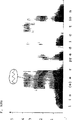
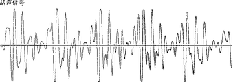
図5は、ある男性によって発音された時の「linear prediction」という言葉に対するスペクトログラムである。このスペクトログラムは、帯域幅が300Hzで、中心周波数が約150Hzから約4kHzの間の範囲にある帯域濾波器によって記録されている。縦軸座標は周波数で、横軸座標は時間であり、黒インクは信号エネルギーの程度である。水平方向の黒い帯状域は、話声の中の主たる周波数帯であり、ホルマント(formant)と呼ばれる。縦の細い線は、信号の急激なエネルギー変化に相当し、したがって過渡成分に対応する。スペクトログラムは普通、ホルマント分析に用いられ、300Hzの帯域幅は過渡分析のためには十分ではない。しかし線の形状の外見からすると、過渡信号は帯域通過濾波器の中心周波数と独立であることが確認される。
前述の通し、蝸牛は無数の帯域通過濾波器をもつともなされるが、多数の帯域通過濾波器を使用せずに過渡信号を検出することができれば有利である。
図6は、どのようにして無数の帯域通過濾波器IBPの和が、低域および高域IBP濾波器IBP1とIBPuの遮断周波数をカバーする帯域をもっている1つの帯域通過濾波BPによってなされるかを示す図である。この帯域通過濾波器BPは最大平坦遅延型のものが望ましい。なぜならこの型の濾波器は過渡状態の形状を保存するのに非常に適しているからである。
実際上は、包絡線を検出するもっとも簡単な方法は、整流器と低域通過濾波器を用いることである。たとえば、「通信システム:電気通信における信号とノイズ入門」マグローヒル好学社1968年、エー ブルース カールソンを参照のこと。等式(10)から、累積過渡成分は、包絡線検出の前に累積される必要のあるIBPの範囲をカバーする高域通過濾波BPを行うことにより検出されることがわかる。包絡線検出は、帯域通過濾波器の中心周波数ωcによる、帯域通過濾波器の帯域の半分をもつ低域通過濾波器への周波数変移に相当する。このことは、低域通過濾波器の遮断周波数が、BPによってカバーされるIBP全部の帯域を決定することを意味する。この原理は図7に示されている。
図7において、デジタル化された音声信号S(t)が、帯域通過あるいは高域通過濾波器BP10に入り、その帯域通過濾波器の出力が整流装置11への入力となり、その出力が低域通過濾波器LP12への入力となる。低域通過濾波器12の出力はftt(t)と表され、包絡線の検出したがって音声信号S(t)の過渡応答の検出を表す。
信号の過渡部分の数学的定義から、h(t)の極がs−平面の負の実軸上に位置することが結論される。このことは衝撃応答が零のまわりに振動していないことを意味する。(過渡応答は非振動信号である。)
等式(10)からIBP濾波器の限界ωcuとωclは単にftt(t)の量の問題であることがわかる。
帯域通過濾波BPはIBP濾波器の過渡応答の和に対する限界を定め、振幅特性がIBP濾波器からの寄与に重みをつける。もしBPのかわりに低域通過濾波器を用いると、h(t)のスペクトルと、低域IBP濾波器の中心周波数に重なりが生じる。帯域通過濾波器BPは少なくとも低域通過濾波器LPのの遮断周波数の2倍に等しい帯域幅をもつべきである。帯域幅と振幅特性は、本発明の方法を用いる時いろいろな信号解析の最適化のため利用することができる。
原理的には、低域通過濾波器LPの極は、数学的過渡検出システムにおいて負の実軸上に位置しているべきである。しかしながら音響信号を取り扱う時、決定要因となるのは蝸牛の特性であるが、衝撃応答の中に有意な振動がないことが望ましい。なぜならそれは音響信号の過渡状態をより不鮮明にするからである。低域通過濾波器LPの遮断周波数は信号の過渡状態に対する表現であり、この周波数は音響信号に関連して、蝸牛の立ち上がり時間に対応する立ち上がり時間となって現れるべきである。遮断周波数は過渡成分の指標とみなされる。ここで下側遮断周波数は立ち上がり時間の遅い信号要素のみの過渡検出にとなってあらわれ、また上側遮断周波数は立ち上がり時間の早い信号要素の過渡検出にとなってあらわれる。
耳からの神経パルスが約1.4kHz以下の周波数に同期しそれ以上の周波数に同期しないという事実は、耳が1.4kHz以下においては音調(tone)指向であり、1.4kHz以上においては過渡指向であることを示す。過渡指向領域においては神経パルスは、信号における急激なエネルギー変化に対応する過渡成分に同期する。
BPの遮断周波数は蝸牛の過渡感度領域に対応するべきである。(理論的にはそれは、耳の感度曲線に対応する振幅特性を持つべきである。)
ヒトの聴覚の感度曲線は下側遮断周波数が約2kHzで、上側遮断周波数が約5kHzであるはずだということを示す。BP濾波器の振幅特性は、個々のIBP濾波器からの寄与に重みをつける。
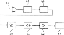
以上の議論から、本発明による過渡検出と分析システムは図8のブロックダイアグラムに示されているように構成される。図8において、音声信号はマイクロホン13に入力され、その出力は低域通過濾波器14を通過し、A/D変換器15によってデジタル化される。A/D変換器の出力S(t)は高域通過あるいは帯域通過濾波器BP10へ導かれ、帯域通過濾波器の出力は整流装置11に入力され、その出力は低域通過濾波器LP12に入力される。図7も参照のこと。低域通過濾波器12の出力はftt(t)と表され、入力信号の過渡成分を表す。過渡成分を解析するために、低域通過濾波器12の出力信号は信号解析や信号認識装置16の中へ導かれることが望ましい。
図9と図10は、図7あるいは図8のシステムにおいて用いるべき好ましい高域通過濾波器および低域通過濾波器の特性を示す図である。図7あるいは図8において高域通過濾波器10として用いられる帯域通過濾波器BPは、少なくとも2000Hz、望ましくは約3000Hzの下側遮断周波数をもつべきである。上側遮断周波数は4500から7000Hzの範囲に、望ましくは約6000Hzにあるべきである。図9に示された特性は3014Hzの下側遮断周波数をもつ。図7あるいは図8において用いられる低域通過濾波器LPは、400から1200Hzの範囲に、望ましくは約700Hzの上側遮断周波数をもつべきである。図10に示された特性は732Hzの上側遮断周波数をもつ。全波整流器を用いて図7あるいは図8の過渡検出システムを構成することも可能である。しかしながら、図7あるいは図8において示されているように、一方向整流器を用いることが望ましい。
図11において、ヒトの耳の感度が示され、音調の音響信号に対する蝸牛の応答を示している。すでに述べたように、感覚は約1.4kHzまでは音調指向であり、1.4kHz以上では過渡指向である。
すでに述べられ、図6に示されているように、IBP濾波器に対する全包絡線は、個々の帯域通過濾波器の包絡線の和として求められ、無数のあるいは多数個の帯域通過濾波器IBPの加算は1つの帯域通過濾波BPによって行うことができる。この原理が図7に示された図面に用いられている。しかしながら、いくつかの帯域通過濾波器の加算はまた、いくつかの個々の帯域通過濾波器の包絡線が検出され加算される濾波器バンクの方法を用いることによって実現することができる。このように、濾波器バンクの中の各部分は、特定の中心周波数をもつ帯域通過濾波器と整流器と低域通過濾波器からなり、低域通過濾波器の出力は、全包絡線を求めるため加算される。
ここで、図12および図13によって示されたいくつかの導入的実験について論じる。
BPおよびLP濾波器の遮断周波数を評価し、この方法の話声認識に対する適性を評価するため、2つの実験が行われた。
1、振幅変調信号を聞き取ることによる実験。
制御された条件のもとでLP濾波器の遮断周波数の第一の表示を得るため、聞き取り試験が、耳に対する感度周波数範囲の振幅変調信号を用いて実行された。通常その範囲においてこのように集中した信号はないため、実験は幾分人工的であり、耳に対し非常に過酷であるため、この実験を確かめることは勧められない。
搬送波周波数は3.5kHzに選ばれ、変調音調(modulation tone)は、数Hzからはじめてだんだん上げていった。350ないし400Hzまでは、包絡線信号は雑音として聞こえる。それ以降は、まずうつろな/u(:)/として聞こえ、800Hzで鋭い/i(:)/のように聞こえる。800Hzをこえると、包絡線信号を聞くことはできなかった。ある時点でさらに音調(tone)を増加させると、いろいろな混合音調が聞こえる。
音声はもちろん搬送波周波数によって支配されていた。しかしLP濾波器に対する遮断周波数はおそらく1ないし1.2kHz以下でなければならないことが示された。
変調指数は約0.75であった。もしそれが1以上の時は、上音(overtones)の導入が認められる。
2、4つの母音に対する過渡信号の解析
図12は男性、女性、子供による、heed、had、hod、およびwho'dにおけるアメリカの母音/i(:)/、
![]()
母音は、普通のカセットレコーダを用いて男性、女性、および子供によって(デンマーク語のアクセントで)発音されたものを記録した。
実験準備
アナログTSD(過渡信号検出器)を図7に従い設計した。設計は操作増幅器LM833をもとにした。
濾波器の種類は以下の通りであった。
BP濾波器は、1dbの脈動(ripple)をもつ4次のチェビシェフ濾波器であった。上側遮断周波数は約6.5kHzであり、低い方は約550Hzから2.6kHzまで調節可能である。
整流器は、負の信号を反転し正の信号に加える、全波整流器であった。
LP濾波器は1.5kHzに遮断周波数をもつように設計された2次のバターワース濾波器であった。(3db遮断周波数を2.1kHzまで測定した。)
母音録音と過渡信号検出
男性、女性、および子供によって発音された4つの母音を、普通のラジオカセットレコーダにより録音した。過渡信号をTSDにより検出し、8ビットA/D変換器により変換し、PC上に記憶させた。録音の時の標本化レートは10kHzであった。しかし録音したデータを解析する時には、1つとびの値だけを取り上げたので、標本化レートは5kHzとなった。8ビットA/D変換器はダイナミックレンジが悪く、したがって分離した(すなわち語中でない)状態で母音を録音することが必要であった。このことはより不確実な発音を生み出す。
図13aから13pは、図12の母音の1つめの過渡解析の実験結果を示す図である。
過渡信号を聞くことにより母音を同定することが可能である。結果の時間変化の目視観察によれば、それぞれ男性、女性、および子供によって発音された同じ母音は、基本的音調に違いが見られるものの、ほとんど同じ特性を持っていることが認められた。デンマーク語の単語「op」の発音/a(:)/を録音する際、p−音も録音され、過渡信号の時間変化からはっきり見ることができる。
過渡信号の解析
過渡信号のパワーは母音によって非常に異なる。母音/a(:)/および/u(:)/の信号は非常に低く(特に男性の声)、ラジオカセットレコーダのボリュームを高いレベルにまで上げる必要があった。これは多量のノイズを発生させた。
まず母音のいろいろな位置から始めて20msの継続時間で5kHzの標本化レートでFFT解析をいくつかおこなった。スペクトルは大変きわだっており母音全体を通じて同じであるように見える。このことは信号中に重要な情報が存在することを強く示す。
共通の特徴を解析するために、20ms(101個の標本)が各母音からランダムに選ばれた。時間信号がハミング窓によって平滑化され、FFTが計算された。図13aから13dには、パワースペクトルが示されており、3つの声が各母音について同じダイアグラムに表示されている。そして対応する過渡信号が、女性によって発音された場合図13eから図13hに、男性によって発音された場合図13iから図13lに、子供によって発音された場合図13mから図13pに、別々に示されている。
スペクトルは次の特徴を持つことが期待されている。
3つの異なった声により発音された同じ母音のスペクトルは、母音に関して共通ないくつかの特徴を備え、声に関連するいくつかの特徴を備える。
同一の声によって発音された違った母音のスペクトルは、その違う母音に関連するいくつかの特徴を備え、声からのいくつかの共通の特徴を備える。
さらにスペクトルの形状が、絶対周波数よりも重要な役割を果たすことが期待される必要がある。
パワースペクトルから次のことがわかる。
/i(:)/(図13a)
最もめだった特徴は、3つの声全てからのスペクトルが、300から400Hzの周波数範囲にきわだった頂上を有し、それらが50Hzの幅であること、そして200から250Hzにきわだった割れ目を有することである。さらに50Hzにおいて、1つの寄与がある。男性の声は150Hzに寄与があり、低い声に起因するものと思われる。
![]()
/a(:)/(図13c)
3つの声すべてに、頂上の250から300Hzがある。周波数範囲はやや低く、/i(:)/の場合ほど際だってはいない。さらに3つの声すべてについて、50Hz及びそれ以下で主要な寄与がある。
/u(:)/(図13d)
子供と女性の声は本当によく似ており、300と350Hzにピークがあり、100Hzに深くて幅の広い谷がある。男性の声にもピークがあり、谷は女性及び子供の場合と同じぐらい幅広であるが深くはない。この理由は、低い声であることと、ラジオカセットレコーダに起因する信号中の多量のノイズが存在することによる可能性がある。
図13aからのpの結果を導きだした実験は、初歩的であると見られるかもしれないが、その結果は、特に多量のノイズとたった8ビットのA/D変換器のもとで用いられた単純な装置であることを考慮に入れると、非常に興味深い。このことにもかかわらず、その結果は際だっている。結果を改良するためのデータ選択は特になく、したがって疑いなく、過渡状態は話声認識にとって決定的重要性をもつ。
全ての情報が500Hz以下の周波数範囲に存在しているように見える。もしそうならば、標本化周波数に要求される条件は1.5kHz以下になり、より多くの処理を平行して行いながら非常に集中的に話声信号を解析することが可能になる。例えば5、20および40msのような、より多くの時間窓をもつことができ、ある音素を検出するためにスペクトル解析(FFT、LPC、CEPSTRUMなど)を用い、別の音素を検出するために時間解析(相関または方法)を用いることができる。
帯域通過濾波された音素のエネルギーにおける変化を補償するため、AGC増幅器を前増幅器(preamplifier)とし、BP濾波器の後に対数またはAGC増幅器をもつ、より巧妙に設計されたTSDを用いることによって、非常によい結果が得られ、話者に依存しないしっかりした話声認識が実現される可能性が高い。もし8ビットA/D変換器の代りに12ビットまたは16ビットA/D変換器を用いれば、さらによい結果が得られるであろう。
図14から図18に示された、他の実験結果を以下に議論する。
本発明による過渡信号成分の抽出方法は、音響入力信号の前処理(pre−process)であるとみなすこともできる。前処理のパラメータをより良き理解し及び/又は決定することができるように、ソフトウェアプログラムが開発され、それを用いることにより、前処理の各処理段階の後で出力信号を提示し出力結果を聞くことができるようになった。
図14と図15に示す話声信号の解析は、コンパック(Compaq)のデスクプロ(Deskpro)4/60iPC上で走るこのソフトウェアプログラムによって行った。この型のPCは、マイクロソフトウィンドウズサウンドシステムと、マイクロホンと、アナログデバイス(Analog Devices)社からの符復号器(codec)チップ(AD1848)を備えている。符復号器チップは標本化と、アンチエイリアシング濾波と、A/D変換を実行する。
図14aと15aに示す話声信号はこのサウンドシステムによって録音されている。話声信号は、11025kHzで16ビット線形PCMによって標本化している。通過帯域はは4.9kHzよりも大きい。
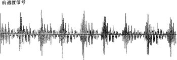
前過渡信号が図14bと15bに示されている。こららの信号は、遮断周波数が3.0kHzの3次IIRデジタル高域通過濾波器によって濾波された話声信号である。濾波器は3次のバターワース濾波器の双線形変換である。
3.0kHzの遮断周波数は、蝸牛の最も感度の高い領域の範囲で帯域通過させるため選ばれた。この場合、これは3.0kHzから4.9kHzを意味する。ここで4.9kHzは符復号器チップによって決められた。高域通過または帯域通過濾波器は、もし等式(10)に従って最大平坦遅延特性をもつならば、最適になる。
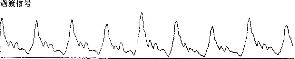
図14cおよび15cに示す過渡信号は、約700Hzに遮断周波数をもつ2次のIIRデジタル低域通過濾波器によって整流され濾波される前過渡信号である。濾波器は2次のバターワース濾波器の双線形変換である。
低域通過濾波器は、蝸牛の過渡応答に対応する過渡パルスの形状を保存する。したがってこれを実行できる濾波器は最適の濾波器になる。蝸牛の神経は約1.4kHzまでの周波数の神経パルスを発生することができる。1.4kHzの過渡指向領域にあるIBP濾波器の帯域幅は、包絡線検出により700Hzの低域通過濾波器に対する遮断周波数に変換される。これが約700Hzの遮断周波数が選ばれた理由である。
過渡信号は、信号におけるエネルギー変化の表現であるとみなすことができる。
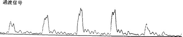
図14と図15に示された全ての信号は、最大信号レベルにまで正規化される。これは最大信号絶対値が32766であることを意味する。図14と15における横軸座標は50msの時間間隔を表し、図14aと15aおよび図14bと15bにおける縦軸座標は対応する話声信号の音声圧力を表し、一方図14cと15cの縦軸座標は対応過渡話声信号のエネルギーを表す。
それぞれ図14a、15a、14b、15b、14cおよび15cに対応する話声、前過渡信号および過渡信号を聞くことが可能である。濾波器特性を選ぶ1つの主たる必要条件は、前記の信号を聞くとき、もとの話声信号に近い音声を信号が維持しなければならないということである。
図7に示されたシステムに関して、図14は男性によって発音されたときの「heat」における母音「i」の曲線を示す。ここで(a)は図7におけるデジタル化した入力信号S(t)に対応する濾波前の話声信号を示し、(b)は図7における帯域通過濾波器10の出力信号に対応する高域通過濾波後の信号を示し、(c)は図7における低域通過濾波器12の出力信号に対応する整流および低域通過濾波後の信号を示す。
図15は「hop」における母音「o」に対する図14と同様の曲線を示す。
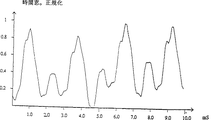
過渡パルスの立ち上がり時間と立ち下がり時間および幅あるいは継続時間は、母音における音声にとって大切であると思われる。図16から18は過渡パルスの測定例を示す。図16aに示される、男性により発音された時の「heat」における母音「i」の時間窓が、図14cに示された処理後の信号に対応する。「heat」における母音「i」が子供により発音された時の、対応する時間窓が図16bに示されている。図16aと16bから、最も主たるパルスの先導エッジと衰微エッジは急峻で、立ち上がり時間と立ち下がり時間が約0.4ms以下であり、主たるパルスの幅は、約50%のレベルで測定したとき約0.8msであることがわかる。
図17aに示される、男性により発音された時の「hop」における母音「o」の時間窓が、図15cに示された処理後の信号に対応する。「hop」における母音「o」が子供により発音された時の、対応する時間窓が図17bに示されている。図17aと17bから、最も主たるパルスの先導エッジと衰微エッジは急峻で、立ち上がり時間と立ち下がり時間が約0.5msであるが、主たるパルスの幅は、約50%のレベルで測定したとき約1.5msであることがわかる。図17bの主たるパルスにおける溝は、知覚に影響を与えるほど深くはない。「hop」における母音「o」は鋭い母音であり、もっと柔らかな母音であればもっとゆっくりした衰微エッジをもつであろうということに注目すべきである。
図18は男性により発音された時の「have」における母音「a」の処理後の信号の時間窓を示す。過渡パルスの形状が、図16から17に示されたパルスと比較してより柔らかい先導エッジと衰微エッジをもつことがわかる。
このように上記の結果から、母音の知覚は過渡パルスの形状から与えられることが結論できる。さらに、上述した信号処理の方法によって音響信号から抽出された過渡成分あるいはパルスを解析することにより、話声信号の母音あるいは音素が過渡パルス又はパルスの形状を同定することにより認識できることが結論できる。
母音あるいは音素において、過渡パルスは繰り返され、その反復周波数が音程(pitch)の知覚を与える。図16において、2つの連続するパルスのの間の時間間隔は、男性の音程約170Hzに対応して約6msであり、図16bにおいて、2つの連続するパルス間の時間間隔は、子供の音程約280Hzに対応して約3.5msである。
このようにまた、上述した信号処理の方法によって音響信号から抽出された過渡成分あるいはパルスを解析することにより、話声信号の音程が過渡パルス間の時間間隔を定量することにより測定できることが結論できる。
このように、本発明の好ましい実施態様によって音響信号を解析するとき、入力信号の高域通過濾波とそれに続く整流と低域通過濾波を含む信号処理の間、音声信号の同一性が保たれることが考慮される。
上記の議論から、本発明は話声認識に使用するのに非常に適した方法を提供することが理解されるべきである。
図19は本発明による話声認識システムのブロックダイアグラムを示す図である。このシステムには、図7の帯域通過濾波器10、整流回路11および低域通過濾波器12を備えた前処理装置20が設けられている。このように本発明の方法によれば、単一の集積回路またはチップに集積することが最も好都合であるこの前処理装置は過渡成分検出装置である。システムはさらに、参照ライブラリ22に接続されたパターン認識装置21、音素測定装置23および単語/文章測定装置24などのような、話声認識システムにおいて通常用いられる装置を備える。図19に示すシステムは、テンプレートマッチングを用いているが、代わりの手段を認識システムにおいて用いてもよい。
図19の参照ライブラリ22は、前処理装置20によって発生することのできる形状に対応するライブラリを記憶すべきである。
単一チップ前処理装置はまた、図8に示される低域通過濾波器14およびまたはA/D変換器15を備えていてもよいことが理解されるべきである。
本発明による前処理は、ラウドスピーカや補聴器や遠距離通信システムなどの音響製品やシステムの品質測定や、音響条件の品質測定などのように、話声あるいは音声の解析、認識、符号化および/または復号化が必要とされる他の多くの電気的システムにおいて用いることができることを理解すべきである。前処理はまた、狭帯域遠距離通信における話声の圧縮および復元に関連して用いることができる。
図10に示されているように、前処理装置に用いられる低域通過濾波器12の遮断周波数は1kHz以下であることが望ましい。このように音響信号の全ての必要な信号情報は、1kHzというかなり狭い周波数範囲のなかで表される。これは、話声信号の通信のためのGSM移動遠距離通信システムに用いられる、毎秒約9000ビットの周波数帯と比較すべきである。本発明の前処理方法又は装置を用いることにより、遠距離通信に用いられる周波数帯を毎秒約1000ビットにまで下げることが可能となり、この分野の通信において多大な節約となる。
このように、本方法は、狭帯域遠距離通信における帯域幅を最適化するのに非常に適しており、遠距離通信システムにおいて音響信号を伝送する時、信号が、伝送され受信機によって受信される前に、ここにおいて述べられた前処理を用いて処理されることは本発明の範囲に入ることが理解されるべきである。処理した信号を伝送する前に信号をデジタル表現に符号化し、音響信号の認識可能な音声像を表す場合にヒトの耳などの動物の耳に知覚される過渡パルス形状を再現するため、符号化し他信号を受信機で復号化することが望ましい。
上述のデジタル伝送の際、受信し復号化し再現する過渡パルスの品質に対するいろいろな必要条件を満たすため、帯域幅を選択する。このように最大で毎秒4000ビットの帯域幅を選ぶことができるが、毎秒約2000ビットの帯域幅を用いることにより、よい品質でパルスを再現することができる。しかしながら、帯域幅は毎秒800から2000ビットの範囲にあることが望ましい。例えば、軍事システムなどにおけるように、再現した信号の品質が高いことより、システム稼働性(performance)の高いことが望まれる遠距離通信システムにおいては、毎秒約400ビットの帯域幅が選択されることに注目すべきである。
デジタル信号を伝送する時、デジタル情報が、処理した音響信号を表す過渡パルスの先導エッジと衰微エッジと継続時間についての情報を含んでいることが望ましい。また一連の同一パルスにおいて第2および後続のパルスが、伝送されたとき繰り返しを指し示すデジタル符号(sign)によって表されることが望ましい。
また本発明のもう1つの目的は、話声合成において用いられる方法を提供することである。
図14から18に実験結果の議論から、各母音あるいは音素の音は、その音素に特定的に対応する主たる過渡パルスの形状によってきまることが理解される。実験から、図16から18の処理したパルスに類似した過渡パルスが、その音素の音を発生するために必要な情報を保持していることが結論された。
図14から18に示された過渡解析のため開発されたソフトウェアを用いれば、縦軸座標が振幅で横軸座標がmsで表した時間である座標系にいくつかの点を置くことによって単純過渡信号を生成することができる。1つの過渡パルスは、1つまたはいくつかの点を置きそれらの点の間に直線または正弦曲線で線を補間し、時間間隔を規定することにより生成できる。信号は300msの間繰り返され、信号は、符復号器チップのD/A変換器によって変換された時、聞くことができる。
パルス立ち上がり時間あるいは先導エッジの形状、パルスの継続時間、および立ち下がり時間あるいは衰微エッジの形状はすべて、話声認識及び/又は合成に用いる過渡パルスの同定、表現及び/又は生成のための重要な特徴であることに注目すべきである。これらの特徴はまた、話声圧縮に関連しても用いられる。
このことは図20から25に示され、話声合成あるいは同定のため用いられる過渡パルスが、それぞれ「heat」における音素「i」、「hop」における「o」、「ongaonga」におけるあるいはデンマーク語の単語「Ole」における「o」、「who」における「u」、デンマーク語の単語「φse」における「φ」、デンマーク語の単語「lys」における「y」の話声合成のためにいかに形成されるべきかを示している。パルスは5msの間繰り返される。
図20から、「heat」における音素「i」は、継続時間が0.3から1.1msの範囲にあり、先導エッジの立ち上がり時間が0.3から0.5msの範囲にある非常に短いパルスによって形成できることがわかる。衰微エッジの立ち下がり時間もまた0.3から0.5msの範囲にあるべきである。
同様に図21から、「hop」における音素「o」は、継続時間が1.3から1.8msの範囲にあり、先導エッジの立ち上がり時間が0.3から0.5msの範囲にあるパルスによって形成できることがわかる。衰微エッジの立ち下がり時間は0.3から0.5msの範囲にあるべきである。
図22から、デンマーク語の単語「Ole」における音素「o」は、継続時間がパルスの上半分において1.3から1.8msの範囲にあり、先導エッジの立ち上がり時間が0.3から0.5msの範囲にあるパルスによって形成できることがわかる。この音素に対する衰微エッジの立ち下がり時間は変わり得るが、1.0から2.0msの範囲にあるべきである。
図23から、「who」における音素「u」は、正弦曲線補間法により、継続時間を1.0から2.0msの範囲の値として過渡パルスを生成することにより形成できることがわかる。望ましい継続時間は約1.5msである。
図24は、デンマーク語の単語「φse」における音素「φ」のパルスを示す図である。ここで先導エッジは0.4から0.6msの範囲の立ち上がり時間とすることができる。衰微エッジの立ち下がり時間は1.0から2.0msの範囲にあるべきである。
図25は、デンマーク語の単語「lys」における音素「y」のパルスを示す図である。ここで先導エッジは1.0から2.0msの範囲の立ち上がり時間とすることができる。衰微エッジの立ち下がり時間もまた1.0から2.0msの範囲にあるべきである。
本発明の前述の原理に従ってヒトの話声を合成する際には、合成すべき話声を構成する一連の音素に対応する一連の過渡パルスを生成することが望ましい。さらにこの一連の音素は、規則に基づく変換を用いて、一連の文字から規定されることが望ましい。
本発明の原理はまた音響製品の品質測定にも用いることができることを理解すべきである。そのような測定において、きちんと規定された過渡信号が音響製品に伝送されるべきであり、それにより応答のひずみを測定できる。ひずみは、図7に示された原理に従って前処理を用いることにより測定できる。
本発明の原理はまた、補聴器において、話声信号のノイズ抑制を改善するために用いることができる。
過渡パルスの固有形状を表す特性ライブラリは、話声信号を固定し話声信号をノイズバックグラウンドから分離するために用いることができる。
提示した実験は、認識し生成することが非常に簡単であるが、話声あるいは音響信号の認識と生成の全分野において大きな意義を持ち得る、音素のいくつかの共通特性を、初めて示した。
本発明の方法とシステムの実行は、時間領域において記述されている。しかしながら、時間領域において記述された過渡信号、過渡成分及び/又は過渡パルスはまた、周波数領域においても対応して記述することができることを理解すべきであり、このことはもちろん本発明の範囲に入るであろう。
また上に記述した信号処理の方法は、デジタル的に、又はアナログ素子を用いて電気的に、又は機械的に、又はそれらのいかなる組合せによっても実行され得るということに注目すべきである。そのような処理方法もまた本発明の範囲に入るであろう。The present invention relates to a method and system for signal processing, wherein features representing an identifiable acoustic image in an acoustic signal are extracted from transient components in the acoustic signal. The result of this processing is used for sound or speech signal identification, quality evaluation of acoustic products or systems such as loudspeakers, hearing aids, and long-distance communication systems, or quality evaluation of acoustic conditions. The method of the present invention can also be used in connection with speech compression and decompression in narrowband telecommunications.
In prior art methods for signal analysis of acoustic signals, the signal is considered to be in a steady state for a short period of time, and a form of short-time spectral analysis is used under this assumption.
The human ear has the ability to simultaneously capture fast audio signals, detect audio frequencies with high accuracy, and distinguish audio signals in complex audio environments. For example, it is possible to understand what the singer is singing under the musical instrument accompaniment.
In the prior art signal analysis method and the method of the present invention, it is assumed that the cochlea in the human ear can be regarded as an infinite number of bandpass filters, IBPs, in the frequency range of the human ear.
The time response f (t) of one bandpass filter due to excitation can be separated into two components, a transient response ft (t) and a steady state response fs (t).
(1) f (t) = ft (t) + fs (t)
Traditional signal processing is based on the steady-state response fs (t), where the transient response ft (t) is assumed to disappear very quickly and not important to perception, eg “Circuit Synthesis Principle” (Mglow Hill, 1959 , Ernesto 5. Coo and Donald O. Pedersen, pp. 12, 9-15, where “forced responses are only considered, and responses due to the initial state of the network are ignored.” It is stated.
Thus, when students are guided into the world of signal analysis, the transient response, i.e. the response due to the initial state of the network, disappears in a very short time and should be ignored. learn. In addition, it is difficult to analyze these transient signals using traditional linear analysis methods.
The ability of humans to hear very short sounds and simultaneously detect frequencies with high accuracy is inconsistent with traditional filter-based spectral analysis. The time window (twice the rise time) of the bandpass filter is inversely proportional to the bandwidth.
(2) tw = 2 / (fu-fl)
Here, f1 is a lower cutoff frequency, and fu is an upper cutoff frequency.
Thus, when a 5 ms rise time is required, the result is a frequency resolution of 400 Hz or less.
Since the detection of these transient components contradicts the high frequency resolution, the detection of these transient components by the human ear must be done in other ways. It has not yet been investigated how the human ear can detect these signals, but the cochlea is in a stationary position when it is not receiving sound, where the cochlea will be very broadband. . When an audio signal is received, the cochlea begins to lock onto the frequency component in the signal. Thus, the cochlea is broadband at the start, but if more than one stable frequency is received, the cochlea is fixed to this frequency with high accuracy.
It is known today that nerve pulses generated from the cochlea are synchronized to the tone frequency when the frequency is less than about 1.4 kHz. If the frequency is greater than 1.4 kHz, pulses are randomly generated less than 1 per
Signal analysis based on filter bank spectral analysis is disclosed in British Patent No. 2213623, which describes a system for phoneme recognition. This system has detection means for detecting the transient part of the speech signal, and the main purpose of the transient detection is to detect the point where the speech spectrum changes most sharply, that is, the peak point. Peak point detection is used for more accurate phoneme segmentation.
The transient analysis of British Patent No. 2213623 is based on spectral analysis and spectral changes and is quite different from the transient analysis of the present invention based on direct transient detection in the time domain.
The invention is based on an approach that differs in principle from all known methods for the analysis of acoustic signals. It has been found according to the invention that signal information relating to the identification of the acoustic signal is present in the transient component of the signal. Thus, the method of the present invention includes the separation of transient components or acoustic signal response, generation of transient pulses corresponding to the transient components, and analysis of the shape of the pulses. In the acoustic signal, the corresponding transient pulses are repeated at time intervals, and the time intervals of these periodic transient pulses are usually also analyzed or determined.
In real life, the human ear reacts to energy changes at high frequencies to recognize phonemes or acoustic images. However, in this method, transient pulses corresponding to the energy changes observed by the ear are extracted at these high frequencies, and then the transient pulses are converted to the low frequency range while preserving the individual characteristics of the acoustic image or phoneme. Is desirable. Thus, using the principles of the present invention, individual characteristics in an acoustic signal can be obtained by examining the converted low frequency signal.
As will be understood from the description of the method of the present invention described below, the concept of extracting pulse transients or shapes uses a preprocessing method that is much simpler than the best design currently in use, and at the same time, Allows you to get much more valuable information about the input signal.
The present invention, according to its broadest aspect, represents the shape of an energy change in an acoustic signal for identifying or representing a feature that can be perceived by an animal ear, such as a human ear, as representing an identifiable acoustic image. About the use of
Before entering into a more detailed description of the features of the method of the present invention, some definitions are given.
In short time analysis, transient components in the signal are subject to definition. The idea is to obtain an expression that gives a response corresponding to the response in the cochlea to a sudden change in signal energy. A sudden change in signal energy corresponds to a transient component in the acoustic signal. Thus, in this context, the term “transient component” refers to any signal that corresponds to a sudden energy change in the acoustic signal. The transient component holds signal information to be analyzed, and in order to analyze this information, the transient component can be converted into a corresponding transient pulse having a different shape. Thus, in this specification, the term “transient pulse” refers to a pulse having an identifiable shape and substantially retaining information on the transient component of the acoustic signal, thereby responding to a sudden change in the energy of the acoustic signal. means. As described above, the transient part of the acoustic signal is repeated at time intervals. Thus, in this specification, the term “periodic” when used in combination with a transient component, response, or pulse refers to any transient component, response, or pulse that is repeated at intervals.
The term “shape” is any time within a given time interval Tp that has a distinct amplitude level compared to the amplitude level outside that interval (time limited or time limited). Represents any function that changes over time. Thus, Tp is the duration of the shape function when the shape function is limited in time, otherwise it is the function portion with a distinctly different amplitude level compared to the amplitude level outside that time interval. It is a duration. As will be appreciated, identification of the shape of the pulse is done appropriately by observing the amplitude of the pulse along the time axis of the pulse.
In order to extract information from the shape of the energy change, one broad aspect of the invention relates to representing the shape of the energy change by the shape of the transient pulse of the signal. However, although several methods can be applied to obtain a transient pulse corresponding to the energy change, it is desirable to use an envelope detection method, in which the envelope is a measure of the energy change of the acoustic signal. It is desirable to detect from the transient response.
The energy changes representing different acoustic images can be phonemes or vowels or other sounds that give abrupt energy changes in the acoustic signal.
Further, according to one aspect of the present invention, the shape of the energy change of the signal is compared with a preset energy change shape representing the identifiable acoustic image, and represents the identifiable acoustic image. A method is provided for identifying in a sound signal an energy change that can be perceived by an animal ear, such as a human ear. For identification purposes, it is desirable that the shape of the energy change be represented by the shape of the transient pulse of the signal, and that the shape of the transient pulse be obtained by detecting the envelope of the transient response of the energy change in the acoustic signal. .
The invention also processes the acoustic signal to reduce the signal bandwidth while substantially retaining the signal information, including extracting the transient component of the acoustic signal and detecting the envelope of the transient component. Regarding the method. It is desirable to identify a transient pulse shape of a signal that can be perceived by an animal ear, such as a human ear, as representing a different acoustic image.
It should be noted that the pulse rise time or leading edge shape, pulse duration and fall time or decay edge shape are all important properties for pulse identification. According to a preferred embodiment of the invention, the shape of the leading edge of the pulse is identified, and the leading edge shape is further determined by determining the rise time and gradient and / or gradient variation of at least part of the leading edge shape. It is desirable.
According to a preferred embodiment of the invention, since the upper part of the pulse contains the necessary information, the rise time and the slope and / or the slope variation of at least the top part of the leading edge shape are measured. The top portion may be defined as the portion that substantially begins at the point where the slope is maximized. The top portion may also be the portion corresponding to 50% above the amplitude of the pulse.
Several methods are used when determining the shape of the pulse, but in the preferred embodiment, the leading edge rise time and slope and / or slope variation are measured based on at least five samples. However, the number of samples may be other suitable numbers. Another desirable method for identifying the shape of the leading edge is performed using a comparison with a reference library. Here, the reference for comparison can be selected based on the leading edge rise time.
It is also desirable to identify the duration of the pulse. Here, the duration of the pulse is defined as the distance from the leading edge to the decaying edge at a predetermined amplitude.
It will also be appreciated that it is desirable to identify the shape of the fading edge of the transient pulse.
The method of the present invention provides a representation of the transient state of the acoustic signal. The method includes bandpass filtering of acoustic signals in the frequency range of the human ear and detection of low-pass filtered envelopes. The envelope can then be analyzed by a known signal analysis method. The envelope is a representation of the transient part of the signal.
Known signal analysis methods to be used for envelope analysis and the characteristics of the bandpass filter to be selected depend on the purpose of the analysis. Its purpose is speech recognition, quality measurement of audio products and acoustic conditions, narrowband telecommunications.
The present invention also includes means for extracting a transient component of an acoustic signal and means for detecting an envelope of the transient component, and is an acoustic for reducing the signal bandwidth while substantially retaining the signal information. The present invention relates to a signal processing system.
Details of the embodiments and the system will become apparent from the detailed discussion of the embodiments of the system and the claims made with respect to the drawings and a mathematical description of the embodiments of the system.
In the following, the invention will be described in more detail in connection with a mathematical description of the principle and the drawings.
FIG. 1 is a diagram showing spectra of a band-pass filter F (ω) and a low-pass filter H (ω).
FIG. 2 is a diagram illustrating zeros and poles in the s-plane for an infinite number of bandpass filters IBP having the same bandwidth.
FIG. 3 shows zeros and poles in the s-plane for an infinite number of bandpass filters IBP having the same Q value.
FIG. 4 is a diagram showing an impulse response for various root locations in the s-plane.
FIG. 5 is a diagram showing a spectrogram for the word “linear prediction”.
FIG. 6 is a diagram showing how the sum of the infinite number of bandpass filters IBP is made by a single bandpass filter.
FIG. 7 is a diagram showing the principle of the transient detection system according to the present invention.
FIG. 8 is a block diagram of a transient detection system according to the present invention.
FIG. 9 is a diagram illustrating the characteristics of a desirable high pass filter to be used in the system of FIG.
FIG. 10 shows the characteristics of a desirable low pass filter to be used in the system of FIG.
FIG. 11 is a diagram showing the sensitivity of the human ear.
Figure 12 shows the American vowel / i (:) /
![]()
FIG. 13 is a diagram showing an experimental result of the first transient analysis of the vowel in FIG.
FIG. 14 is a diagram illustrating a curve after processing the vowel “i” in “heat”.
FIG. 15 is a diagram illustrating a curve similar to FIG. 12 for the vowel “o” in “hop”.
FIG. 16 is a diagram illustrating a normalized time window with respect to the curve after processing of the vowel “i” in “heat”.
FIG. 17 is a diagram illustrating a normalized time window for the vowel “o” in “hop”.
FIG. 18 is a diagram illustrating a normalized time window for the vowel “a” in “have”.
FIG. 19 is a block diagram of the speech recognition system according to the present invention.
20 to 25 show phonemes “i” in “heat”, “o” in “hop”, “o” in “ongaonga”, “u” in Danish word “hus”, Danish word “φse”, respectively. Is a transient pulse for voice synthesis of “φ” in “” and “y” in Danish word “lys”.
First, a mathematical explanation of the principles of the present invention is given.
The band-pass filter is expressed by an impulse response in the time domain, and is expressed by the following equation.
f (t) = h (t) cos (ω c t)
Where h (t) is the shock response to the low pass filter and ω c Is the center frequency of the bandpass filter f (t). cos (ω c The term t) has a center frequency of ω c Is considered to represent the frequency shift of the low-pass filter to the other band-pass filter.
This is illustrated in FIG. 1, where f (ω) and H (ω) are the corresponding frequency characteristics of f (t) and h (t), respectively.
Suppose that the IBP filter consists of a simple bandpass filter BP with zero at the origin and two (complementary) complex poles in the left half plane of the complex s-plane, and the IBP filter poles are in a straight line Is located at
1) If the bandwidth is the same for all IBP filters, the rise time and delay time will be the same for all filters, but Q = fc / (fu-fl) is inversely proportional to the center frequency fc To do. Zeros and poles are shown in FIG.
2) If the Q values are the same for all of the filters, the rise time and delay time are inversely proportional to the center frequency, but the bandwidth is proportional to the center frequency. Zeros and poles are shown in FIG.
Assume that the rise time and delay time are the same for the IBP filter in the frequency range of interest in the transient analysis. If not, assume that the brain compensates for this. The effect is only that the rise time is slower and the delay time is longer as the frequency is lowered (if the Q value is the same). The rhythm and shape of the transient component are the same.
In short time analysis, transient components in the signal are subject to definition. The idea is to obtain an expression that gives a response corresponding to the response in the cochlea to a sudden change in signal energy. A sudden change in signal energy corresponds to a transient component in the acoustic signal.
The composition of transient and steady state components in the signal is identified by envelope detection. Here, the steady state component is a DC component in the detected envelope, and the transient component is identified as a change in the envelope level.
The transient response is identified by envelope detection.
The envelope of the impact response is expressed by the following equation.
![]()
![]()
By substituting equation (3) into equation (4), the following equation is obtained.
![]()
![]()
(7)
![]()
(8) ft (t) = | h (t) |
Under this condition, the envelope of the shock response is independent of the center frequency. This is illustrated in FIG. 4 and shows how different impact responses produce the same envelope.
As a result of equation (8), the total envelope for the IBP filter is the sum of the envelopes for the individual bandpass filters.
The cumulative transient response ftt (t) is expressed by adding ft (t) in this way. This sum is expressed by the following equation.
(10) ftt (t) = | h (t) | (ω cu −ω cl )
Where ω cl Is the center frequency for the low-pass IBP filter and ω cu Is the center frequency for the high-pass IBP filter.
FIG. 5 is a spectrogram for the word “linear prediction” when pronounced by a man. The spectrogram is recorded by a bandpass filter with a bandwidth of 300 Hz and a center frequency in the range between about 150 Hz and about 4 kHz. The vertical axis coordinate is frequency, the horizontal axis coordinate is time, and black ink is the degree of signal energy. The black horizontal band in the horizontal direction is the main frequency band in the voice and is called formant. The vertical thin line corresponds to an abrupt energy change in the signal and thus corresponds to the transient component. The spectrogram is usually used for formant analysis and a bandwidth of 300 Hz is not sufficient for transient analysis. However, the appearance of the line shape confirms that the transient signal is independent of the center frequency of the bandpass filter.
As described above, the cochlea has an infinite number of band-pass filters, but it is advantageous if a transient signal can be detected without using a large number of band-pass filters.
FIG. 6 shows how the sum of myriad bandpass filters IBP is reduced to low and high band IBP filters IBP. 1 And IBP u It is a figure which shows what is done by one band pass filter BP which has the zone | band which covers the cutoff frequency of this. This band pass filter BP is preferably of the maximum flat delay type. This is because this type of filter is very suitable for preserving the shape of the transient state.
In practice, the simplest way to detect the envelope is to use a rectifier and a low-pass filter. See, for example, “Communications Systems: Introduction to Signals and Noise in Telecommunications”, McGraw-Hill Kogakusha, 1968, A Bruce Carlson. From equation (10), it can be seen that the accumulated transient component is detected by performing a high-pass filtered BP that covers the range of IBP that needs to be accumulated prior to envelope detection. Envelope detection is based on the center frequency ω of the bandpass filter c Corresponds to a frequency shift to a low-pass filter having half the band of the band-pass filter. This means that the cut-off frequency of the low-pass filter determines the entire band of IBP covered by the BP. This principle is illustrated in FIG.
In FIG. 7, the digitized audio signal S (t) enters the bandpass or high-pass filter BP10, the output of the bandpass filter becomes the input to the
From the mathematical definition of the transient part of the signal, it is concluded that the pole of h (t) is located on the negative real axis of the s-plane. This means that the impact response is not oscillating around zero. (The transient response is a non-vibrating signal.)
From equation (10), the limit ω of the IBP filter cu And ω cl Is simply a matter of the amount of ftt (t).
The bandpass filter BP sets a limit on the sum of the transient response of the IBP filter, and the amplitude characteristic weights the contribution from the IBP filter. If a low-pass filter is used instead of BP, an overlap occurs between the spectrum of h (t) and the center frequency of the low-pass IBP filter. The bandpass filter BP should have a bandwidth at least equal to twice the cutoff frequency of the lowpass filter LP. Bandwidth and amplitude characteristics can be used to optimize various signal analysis when using the method of the present invention.
In principle, the pole of the low-pass filter LP should be located on the negative real axis in the mathematical transient detection system. However, when dealing with acoustic signals, the determinant is the characteristics of the cochlea, but it is desirable that there is no significant vibration in the impact response. This is because it makes the transient state of the acoustic signal more blurred. The cut-off frequency of the low-pass filter LP is an expression for the transient state of the signal, and this frequency should appear in relation to the acoustic signal as a rise time corresponding to the rise time of the cochlea. The cut-off frequency is regarded as an indicator of transient components. Here, the lower cut-off frequency appears for transient detection of only signal elements having a slow rise time, and the upper cut-off frequency appears for transient detection of signal elements with a quick rise time.
The fact that nerve pulses from the ear synchronize to frequencies below about 1.4kHz and not above it is tone-oriented when the ear is below 1.4kHz, and transient oriented when above 1.4kHz. It shows that. In the transient-oriented region, the nerve pulse is synchronized with a transient component corresponding to a sudden energy change in the signal.
The cutoff frequency of BP should correspond to the cochlear transient sensitivity region. (Theoretically, it should have an amplitude characteristic that corresponds to the ear sensitivity curve.)
The human auditory sensitivity curve shows that the lower cutoff frequency should be about 2kHz and the upper cutoff frequency should be about 5kHz. The amplitude characteristics of the BP filter weight the contribution from individual IBP filters.
From the above discussion, the transient detection and analysis system according to the present invention is configured as shown in the block diagram of FIG. In FIG. 8, the audio signal is input to the
9 and 10 show the characteristics of the preferred high and low pass filters to be used in the system of FIG. 7 or FIG. The band-pass filter BP used as the high-
In FIG. 11, the sensitivity of the human ear is shown, showing the cochlear response to an acoustic signal of tone. As already mentioned, the sensation is tone-oriented up to about 1.4 kHz and transient-oriented above 1.4 kHz.
As already mentioned and shown in FIG. 6, the total envelope for the IBP filter is determined as the sum of the envelopes of the individual band pass filters, and can be used for infinite or multiple band pass filters IBP. The addition can be performed by one band pass filter BP. This principle is used in the drawing shown in FIG. However, the summation of several bandpass filters can also be achieved by using a filter bank method in which the envelopes of several individual bandpass filters are detected and summed. Thus, each part in the filter bank consists of a band-pass filter, a rectifier, and a low-pass filter having a specific center frequency, and the output of the low-pass filter is to obtain the entire envelope. Is added.
We will now discuss some introductory experiments illustrated by FIG. 12 and FIG.
Two experiments were performed to evaluate the cutoff frequency of BP and LP filters and to evaluate the suitability of this method for speech recognition.
1. Experiment by listening to an amplitude-modulated signal.
To obtain a first indication of the LP filter cutoff frequency under controlled conditions, a listening test was performed using an amplitude modulated signal in the sensitivity frequency range for the ear. Since there is usually no such concentrated signal in that range, the experiment is somewhat artificial and very harsh on the ears, so it is not recommended to confirm this experiment.
The carrier frequency was chosen to be 3.5 kHz, and the modulation tone gradually increased from a few Hz. From 350 to 400 Hz, the envelope signal sounds as noise. After that, it first sounds as a relaxed / u (:) /, and sounds like a sharp / i (:) / at 800Hz. Beyond 800 Hz, I could not hear the envelope signal. If you increase the tone at some point, you can hear various mixed tones.
The voice was of course governed by the carrier frequency. However, it has been shown that the cut-off frequency for the LP filter should probably be 1 to 1.2 kHz or less.
The modulation index was about 0.75. If it is greater than 1, the introduction of overtones is allowed.
Analysis of transient signals for two or four vowels
Figure 12 shows American vowels / i (:) / in heed, had, hod, and who'd by men, women, and children,
![]()
Vowels were recorded by men, women, and children (with Danish accents) using a normal cassette recorder.
Preparation for experiment
An analog TSD (transient signal detector) was designed according to FIG. The design was based on the operational amplifier LM833.
The types of filters were as follows.
The BP filter was a 4th order Chebyshev filter with 1 db ripple. The upper cut-off frequency is about 6.5 kHz, and the lower one can be adjusted from about 550 Hz to 2.6 kHz.
The rectifier was a full wave rectifier that inverts the negative signal and adds it to the positive signal.
The LP filter was a second order Butterworth filter designed to have a cutoff frequency of 1.5 kHz. (The 3db cutoff frequency was measured up to 2.1kHz.)
Vowel recording and transient signal detection
Four vowels pronounced by men, women, and children were recorded with an ordinary radio cassette recorder. Transient signals were detected by TSD, converted by an 8-bit A / D converter, and stored on a PC. The sampling rate at the time of recording was 10 kHz. However, when analyzing the recorded data, only one value was taken up, so the sampling rate was 5 kHz. The 8-bit A / D converter had a poor dynamic range and therefore needed to record vowels in a separate (ie not in-word) state. This creates a more uncertain pronunciation.
13a to 13p are diagrams showing experimental results of the first transient analysis of the vowel in FIG.
It is possible to identify vowels by listening to transient signals. Visual observations of the resulting temporal changes showed that the same vowels, pronounced by men, women, and children, respectively, had almost the same characteristics, although there were differences in basic tones. When recording the pronunciation / a (:) / of the Danish word “op”, the p-sound is also recorded and can be clearly seen from the time variation of the transient signal.
Transient signal analysis
The power of the transient signal varies greatly depending on the vowel. The signals of vowels / a (:) / and / u (:) / were very low (especially male voices), and the volume of the radio cassette recorder had to be raised to a high level. This generated a lot of noise.
First, we started from various positions of the vowel and performed some FFT analysis at a sampling rate of 5kHz with a duration of 20ms. The spectrum is very sharp and seems to be the same throughout the vowel. This strongly indicates that there is important information in the signal.
To analyze common features, 20ms (101 samples) were randomly selected from each vowel. The time signal was smoothed by a Hamming window and the FFT was calculated. Figures 13a to 13d show the power spectrum, with three voices displayed on the same diagram for each vowel. The corresponding transient signals are shown separately in FIGS. 13e to 13h when pronounced by a woman, in FIGS. 13i to 13l when pronounced by a man, and in FIGS. 13m to 13p when pronounced by a child. ing.
The spectrum is expected to have the following characteristics:
The spectrum of the same vowel pronounced by three different voices has some features common to vowels and some features related to the voice.
The spectrum of different vowels pronounced by the same voice has some features associated with the different vowels and some common features from the voice.
Furthermore, the shape of the spectrum needs to be expected to play a more important role than absolute frequency.
The following can be seen from the power spectrum.
/ i (:) / (Figure 13a)
The most prominent feature is that the spectrum from all three voices has a peak that was noticeable in the frequency range of 300 to 400 Hz, they are 50 Hz wide, and has a crack that was noticeable from 200 to 250 Hz. It is. There is also a contribution at 50 Hz. The male voice contributes to 150Hz and is probably due to the low voice.
![]()
/ a (:) / (Figure 13c)
All three voices have a peak of 250-300Hz. The frequency range is slightly lower and not as distinct as with / i (:) /. In addition, for all three voices, there is a major contribution at 50Hz and below.
/ u (:) / (Fig. 13d)
The voices of children and women are very similar, with peaks at 300 and 350 Hz and a deep and wide valley at 100 Hz. There is also a peak in male voices, and the valleys are as wide but not deep as women and children. This may be due to the low voice and the presence of a large amount of noise in the signal due to the radio cassette recorder.
The experiment leading to the p result from Figure 13a may be seen as rudimentary, but the result is used especially with a large amount of noise and only an 8-bit A / D converter. It is very interesting to consider that it is a simple device. Despite this, the results are striking. There is no particular data selection to improve the results, so no doubt, transients are of crucial importance for speech recognition.
All information appears to be in the frequency range below 500Hz. If so, the required condition for the sampling frequency is 1.5 kHz or less, and it becomes possible to analyze the speech signal very intensively while performing more processes in parallel. Can have more time windows, eg 5, 20 and 40ms, use spectral analysis (FFT, LPC, CEPSTRUM, etc.) to detect one phoneme and time to detect another phoneme Analysis (correlation or method) can be used.
To compensate for changes in the energy of bandpass filtered phonemes, the AGC amplifier is a preamplifier, and by using a more skillfully designed TSD with a logarithmic or AGC amplifier after the BP filter, Therefore, there is a high possibility that a good result will be obtained and a solid speech recognition independent of the speaker will be realized. Even better results will be obtained if a 12-bit or 16-bit A / D converter is used instead of an 8-bit A / D converter.
Other experimental results shown in FIGS. 14 to 18 are discussed below.
The transient signal component extraction method according to the present invention can also be regarded as a pre-process of an acoustic input signal. A software program has been developed and used to present the output signal and listen to the output result after each processing stage of the preprocessing so that the parameters of the preprocessing can be better understood and / or determined. I was able to do it.
The speech signal analysis shown in FIGS. 14 and 15 was performed by this software program running on a
The speech signals shown in FIGS. 14a and 15a are recorded by this sound system. The speech signal is sampled by a 16-bit linear PCM at 11025 kHz. The passband is greater than 4.9kHz.
The pre-transient signal is shown in FIGS. 14b and 15b. These signals are speech signals filtered by a 3rd order IIR digital high pass filter with a cutoff frequency of 3.0 kHz. The filter is a bilinear transformation of a third order Butterworth filter.
A cut-off frequency of 3.0 kHz was chosen to pass the band over the most sensitive region of the cochlea. In this case, this means from 3.0 kHz to 4.9 kHz. Here, 4.9 kHz is determined by the codec chip. A high pass or band pass filter is optimal if it has a maximum flat delay characteristic according to equation (10).
The transient signals shown in FIGS. 14c and 15c are pre-transient signals that are rectified and filtered by a second order IIR digital low pass filter having a cutoff frequency of about 700 Hz. The filter is a bilinear transformation of a second order Butterworth filter.
The low pass filter preserves the shape of the transient pulse corresponding to the cochlear transient response. A filter that can do this is therefore an optimal filter. Cochlear nerves can generate nerve pulses with frequencies up to about 1.4 kHz. The bandwidth of the IBP filter in the 1.4 kHz transient pointing region is converted to a cut-off frequency for the 700 Hz low pass filter by envelope detection. This is why a cutoff frequency of about 700 Hz was chosen.
A transient signal can be regarded as a representation of the energy change in the signal.
All signals shown in FIGS. 14 and 15 are normalized to the maximum signal level. This means that the maximum signal absolute value is 32766. The horizontal coordinate in FIGS. 14 and 15 represents a 50 ms time interval, and the vertical coordinate in FIGS. 14a and 15a and 14b and 15b represents the voice pressure of the corresponding speech signal, while the vertical coordinate in FIGS. 14c and 15c. Represents the energy of the corresponding transient speech signal.
It is possible to hear speech, pre-transient signals and transient signals corresponding to FIGS. 14a, 15a, 14b, 15b, 14c and 15c, respectively. One major requirement for choosing filter characteristics is that when listening to the signal, the signal must maintain a sound close to the original speech signal.
For the system shown in FIG. 7, FIG. 14 shows the curve of the vowel “i” in “heat” when pronounced by a man. Here, (a) shows a speech signal before filtering corresponding to the digitized input signal S (t) in FIG. 7, and (b) shows a high frequency band corresponding to the output signal of the
FIG. 15 shows a curve similar to FIG. 14 for the vowel “o” in “hop”.
The rise and fall times and width or duration of the transient pulse appears to be important for speech in vowels. 16 to 18 show examples of transient pulse measurement. The time window of the vowel “i” in “heat” when pronounced by a male, shown in FIG. 16a, corresponds to the processed signal shown in FIG. 14c. The corresponding time window when the vowel “i” in “heat” is pronounced by the child is shown in FIG. 16b. From Figures 16a and 16b, the leading and decaying edges of the most main pulse are steep, the rise and fall times are less than about 0.4 ms, and the main pulse width is about 0.8 when measured at a level of about 50%. It turns out that it is ms.
The time window of the vowel “o” in “hop” when pronounced by a man shown in FIG. 17a corresponds to the processed signal shown in FIG. 15c. The corresponding time window when the vowel “o” in “hop” is pronounced by the child is shown in FIG. 17b. From Figures 17a and 17b, the leading and decaying edges of the most dominant pulse are steep, with rise and fall times of about 0.5 ms, but the width of the main pulse is about 1.5 when measured at a level of about 50%. It turns out that it is ms. The grooves in the main pulse of FIG. 17b are not deep enough to affect perception. It should be noted that the vowel “o” in “hop” is a sharp vowel, and a softer vowel will have a slower decaying edge.
FIG. 18 shows the time window of the signal after processing of the vowel “a” in “have” when pronounced by a man. It can be seen that the shape of the transient pulse has softer leading and decaying edges compared to the pulses shown in FIGS.
Thus, from the above results, it can be concluded that the perception of vowels is given by the shape of the transient pulse. Furthermore, by analyzing the transient component or pulse extracted from the acoustic signal by the signal processing method described above, it can be concluded that the vowel or phoneme of the speech signal can be recognized by identifying the shape of the transient pulse or pulse.
In vowels or phonemes, transient pulses are repeated, and the repetition frequency gives a perception of pitch. In FIG. 16, the time interval between two consecutive pulses is about 6 ms, corresponding to a male pitch of about 170 Hz, and in FIG. 16b, the time interval between two consecutive pulses is about the pitch of a child. It is about 3.5ms corresponding to 280Hz.
Thus, by analyzing the transient component or pulse extracted from the acoustic signal by the signal processing method described above, it can be concluded that the pitch of the speech signal can be measured by quantifying the time interval between the transient pulses. .
Thus, when analyzing an acoustic signal according to a preferred embodiment of the present invention, the identity of the audio signal is maintained during signal processing including high pass filtering of the input signal followed by rectification and low pass filtering. It is considered.
From the above discussion, it should be understood that the present invention provides a very suitable method for use in speech recognition.
FIG. 19 is a block diagram of the speech recognition system according to the present invention. The system is provided with a
The
It should be understood that the single chip pre-processor may also comprise a
The pre-processing according to the present invention includes analysis, recognition, encoding and / or speech or speech analysis such as quality measurement of acoustic products and systems such as loudspeakers, hearing aids, and telecommunication systems, and quality measurement of acoustic conditions. Or it should be understood that it can be used in many other electrical systems where decoding is required. Pre-processing can also be used in connection with speech compression and decompression in narrowband telecommunications.
As shown in FIG. 10, it is desirable that the cut-off frequency of the low-
Thus, this method is very suitable for optimizing the bandwidth in narrowband telecommunications, and when transmitting an acoustic signal in a telecommunications system, the signal is transmitted and received by the receiver. It should be understood that, prior to processing, it is within the scope of the present invention to be processed using the preprocessing described herein. Encode the signal into a digital representation before transmitting the processed signal and encode it to reproduce the transient pulse shape perceived by animal ears such as the human ear when representing a recognizable audio image of an acoustic signal. It is desirable to decode other signals at the receiver.
In the digital transmission described above, the bandwidth is selected to meet various requirements for the quality of the transient pulse received, decoded and reproduced. In this way, a maximum bandwidth of 4000 bits per second can be selected, but by using a bandwidth of about 2000 bits per second, pulses can be reproduced with good quality. However, the bandwidth is preferably in the range of 800 to 2000 bits per second. For example, in a telecommunications system where high system performance is desired due to the high quality of the reproduced signal, such as in military systems, a bandwidth of approximately 400 bits per second should be selected. Should be noted.
When transmitting a digital signal, it is desirable that the digital information includes information about the leading and decay edges and duration of the transient pulse representing the processed acoustic signal. It is also desirable that the second and subsequent pulses in a series of identical pulses be represented by a digital sign that indicates repetition when transmitted.
Another object of the present invention is to provide a method used in speech synthesis.
From the discussion of the experimental results in FIGS. 14 to 18, it is understood that the sound of each vowel or phoneme depends on the shape of the main transient pulse corresponding specifically to the phoneme. From the experiments, it was concluded that a transient pulse similar to the processed pulse of FIGS. 16 to 18 retains the information necessary to generate the phoneme sound.
Using the software developed for the transient analysis shown in Figures 14 to 18, simple transients can be achieved by placing several points in a coordinate system where the vertical coordinate is amplitude and the horizontal coordinate is time in ms. A signal can be generated. A transient pulse can be generated by placing one or several points, interpolating a line or sine curve between those points, and defining a time interval. The signal is repeated for 300 ms and can be heard when converted by the D / A converter of the codec chip.
Pulse rise time or leading edge shape, pulse duration, and fall time or decay edge shape are all important for the identification, representation and / or generation of transient pulses used in speech recognition and / or synthesis. It should be noted that it is a feature. These features are also used in connection with speech compression.
This is illustrated in FIGS. 20 to 25, where the transient pulses used for speech synthesis or identification are the phonemes “i” in “heat”, “o” in “hop”, “ongaonga” or Danish Formed for speech synthesis of “o” in word “Ole”, “u” in “who”, “φ” in Danish word “φse”, “y” in Danish word “lys” Indicates what should be done. The pulse is repeated for 5ms.
From FIG. 20, it can be seen that the phoneme “i” in “heat” can be formed by a very short pulse whose duration is in the range of 0.3 to 1.1 ms and the leading edge rise time is in the range of 0.3 to 0.5 ms. The fall time of the decaying edge should also be in the range of 0.3 to 0.5 ms.
Similarly, FIG. 21 shows that the phoneme “o” in “hop” can be formed by a pulse whose duration is in the range of 1.3 to 1.8 ms and the leading edge rise time is in the range of 0.3 to 0.5 ms. The fall time of the decaying edge should be in the range of 0.3 to 0.5 ms.
From FIG. 22, the phoneme “o” in the Danish word “Ole” has a pulse whose duration is in the range of 1.3 to 1.8 ms in the upper half of the pulse and the leading edge rise time is in the range of 0.3 to 0.5 ms. It can be seen that it can be formed. The decay edge fall time for this phoneme can vary, but should be in the range of 1.0 to 2.0 ms.
From FIG. 23, it can be seen that the phoneme “u” in “who” can be formed by generating a transient pulse with a duration in the range of 1.0 to 2.0 ms by the sinusoidal interpolation method. The desired duration is about 1.5 ms.
FIG. 24 is a diagram showing pulses of phoneme “φ” in Danish word “φse”. Here, the leading edge can have a rise time in the range of 0.4 to 0.6 ms. The fall time of the decaying edge should be in the range of 1.0 to 2.0ms.
FIG. 25 is a diagram showing pulses of phoneme “y” in Danish word “lys”. Here, the leading edge can have a rise time in the range of 1.0 to 2.0 ms. The fall time of the decaying edge should also be in the range of 1.0 to 2.0 ms.
When synthesizing human speech in accordance with the aforementioned principles of the present invention, it is desirable to generate a series of transient pulses corresponding to a series of phonemes making up the speech to be synthesized. Furthermore, the series of phonemes is preferably defined from the series of characters using a rule-based transformation.
It should be understood that the principles of the present invention can also be used to measure the quality of acoustic products. In such a measurement, a well-defined transient signal should be transmitted to the acoustic product so that the distortion of the response can be measured. The strain can be measured by using a pretreatment according to the principle shown in FIG.
The principles of the present invention can also be used in hearing aids to improve noise suppression of speech signals.
A characteristic library representing the intrinsic shape of the transient pulse can be used to fix the speech signal and separate the speech signal from the noise background.
The presented experiments show for the first time some common characteristics of phonemes that are very easy to recognize and generate, but can have significant significance in all areas of speech or acoustic signal recognition and generation.
The implementation of the method and system of the present invention is described in the time domain. However, it should be understood that transient signals, transient components and / or transient pulses described in the time domain can also be described correspondingly in the frequency domain, which of course falls within the scope of the invention. Will.
It should also be noted that the signal processing methods described above can be performed digitally, electrically using analog elements, mechanically, or any combination thereof. Such processing methods will also fall within the scope of the present invention.
Claims (43)
Applications Claiming Priority (3)
| Application Number | Priority Date | Filing Date | Title |
|---|---|---|---|
| DK93464A DK46493D0 (en) | 1993-04-22 | 1993-04-22 | METHOD OF SIGNAL TREATMENT FOR DETERMINING TRANSIT CONDITIONS IN AUDITIVE SIGNALS |
| DK0464/93 | 1993-04-22 | ||
| PCT/DK1994/000164 WO1994025958A2 (en) | 1993-04-22 | 1994-04-22 | Method and system for detecting and generating transient conditions in auditory signals |
Publications (2)
| Publication Number | Publication Date |
|---|---|
| JPH08509556A JPH08509556A (en) | 1996-10-08 |
| JP3636460B2 true JP3636460B2 (en) | 2005-04-06 |
Family
ID=8093848
Family Applications (1)
| Application Number | Title | Priority Date | Filing Date |
|---|---|---|---|
| JP52376294A Expired - Fee Related JP3636460B2 (en) | 1993-04-22 | 1994-04-22 | Method and system for detecting and generating transients in acoustic signals |
Country Status (11)
| Country | Link |
|---|---|
| US (1) | US5884260A (en) |
| EP (1) | EP0737351B1 (en) |
| JP (1) | JP3636460B2 (en) |
| KR (1) | KR960702145A (en) |
| CN (1) | CN1158642C (en) |
| AT (1) | ATE178155T1 (en) |
| AU (1) | AU6535994A (en) |
| DE (1) | DE69417445T2 (en) |
| DK (1) | DK46493D0 (en) |
| FI (1) | FI955025A (en) |
| WO (1) | WO1994025958A2 (en) |
Families Citing this family (39)
| Publication number | Priority date | Publication date | Assignee | Title |
|---|---|---|---|---|
| AU6785696A (en) * | 1995-09-05 | 1997-03-27 | Frank Uldall Leonhard | Method and system for processing auditory signals |
| US6424722B1 (en) * | 1997-01-13 | 2002-07-23 | Micro Ear Technology, Inc. | Portable system for programming hearing aids |
| US7787647B2 (en) | 1997-01-13 | 2010-08-31 | Micro Ear Technology, Inc. | Portable system for programming hearing aids |
| US6366863B1 (en) * | 1998-01-09 | 2002-04-02 | Micro Ear Technology Inc. | Portable hearing-related analysis system |
| JP2002507776A (en) * | 1998-03-13 | 2002-03-12 | レオンハルト,フランク,ウルダル | Signal processing method for analyzing transients in audio signals |
| AUPQ366799A0 (en) * | 1999-10-26 | 1999-11-18 | University Of Melbourne, The | Emphasis of short-duration transient speech features |
| GB9928420D0 (en) * | 1999-12-02 | 2000-01-26 | Ibm | Interactive voice response system |
| AU2001229591A1 (en) | 2000-01-20 | 2001-07-31 | Starkey Laboratories, Inc. | Hearing aid systems |
| DE60129771T2 (en) * | 2000-03-15 | 2008-04-30 | Koninklijke Philips Electronics N.V. | LAGUERRE FUNCTION FOR AUDIO CODING |
| DE10031832C2 (en) * | 2000-06-30 | 2003-04-30 | Cochlear Ltd | Hearing aid for the rehabilitation of a hearing disorder |
| WO2002025998A1 (en) * | 2000-09-20 | 2002-03-28 | Leonhard Research A/S | A method of measuring the impulse response capability of a system |
| WO2002080618A1 (en) * | 2001-03-30 | 2002-10-10 | Leonhard Research A/S | Noise suppression in measurement of a repetitive signal |
| CN1274153C (en) * | 2001-04-18 | 2006-09-06 | 皇家菲利浦电子有限公司 | Audio coding with partial encryption |
| EP1280138A1 (en) * | 2001-07-24 | 2003-01-29 | Empire Interactive Europe Ltd. | Method for audio signals analysis |
| JP2003256265A (en) * | 2002-02-18 | 2003-09-10 | Internatl Business Mach Corp <Ibm> | Search memory, controller for memory search, and memory search method |
| JP2003256267A (en) * | 2002-02-28 | 2003-09-10 | Internatl Business Mach Corp <Ibm> | Data processing method, memory region search system using the same, and program |
| DE10214407C1 (en) * | 2002-03-30 | 2003-06-18 | Klippel Gmbh | Measuring, evaluating and noise recognition device for signal transmission or storage systems, has estimator which supplies estimated parameter to model system whose output indicates instantaneous noise and distortion |
| KR20030083903A (en) * | 2002-04-23 | 2003-11-01 | 엘지전자 주식회사 | Phoneme boundary adjustment method for text/speech conversion |
| CN100339886C (en) * | 2003-04-10 | 2007-09-26 | 联发科技股份有限公司 | Coding device capable of detecting transient position of sound signal and its coding method |
| US20050010413A1 (en) * | 2003-05-23 | 2005-01-13 | Norsworthy Jon Byron | Voice emulation and synthesis process |
| WO2005015543A1 (en) * | 2003-08-06 | 2005-02-17 | Frank Uldall Leonhard | Method for analysing signals containing pulses |
| US20050091060A1 (en) * | 2003-10-23 | 2005-04-28 | Wing Thomas W. | Hearing aid for increasing voice recognition through voice frequency downshift and/or voice substitution |
| US7472827B2 (en) * | 2004-05-17 | 2009-01-06 | American Express Travel Related Services Company, Inc. | Limited use PIN system and method |
| US20060112812A1 (en) * | 2004-11-30 | 2006-06-01 | Anand Venkataraman | Method and apparatus for adapting original musical tracks for karaoke use |
| DK1925185T3 (en) * | 2005-09-12 | 2009-04-20 | Siemens Audiologische Technik | Method of attenuating interfering noise and corresponding hearing aid |
| DE102005043314B4 (en) * | 2005-09-12 | 2009-08-06 | Siemens Audiologische Technik Gmbh | Method for attenuating background noise and corresponding hearing device |
| CA2601662A1 (en) | 2006-09-18 | 2008-03-18 | Matthias Mullenborn | Wireless interface for programming hearing assistance devices |
| US8046218B2 (en) * | 2006-09-19 | 2011-10-25 | The Board Of Trustees Of The University Of Illinois | Speech and method for identifying perceptual features |
| EP2031581A1 (en) | 2007-08-31 | 2009-03-04 | Deutsche Thomson OHG | Method for identifying an acoustic event in an audio signal |
| US8983832B2 (en) * | 2008-07-03 | 2015-03-17 | The Board Of Trustees Of The University Of Illinois | Systems and methods for identifying speech sound features |
| US20110178799A1 (en) * | 2008-07-25 | 2011-07-21 | The Board Of Trustees Of The University Of Illinois | Methods and systems for identifying speech sounds using multi-dimensional analysis |
| US8326625B2 (en) * | 2009-11-10 | 2012-12-04 | Research In Motion Limited | System and method for low overhead time domain voice authentication |
| US8321209B2 (en) | 2009-11-10 | 2012-11-27 | Research In Motion Limited | System and method for low overhead frequency domain voice authentication |
| US10129671B2 (en) * | 2013-02-22 | 2018-11-13 | Securboration, Inc. | Hearing device adjustment based on categorical perception |
| EP2858381A1 (en) * | 2013-10-03 | 2015-04-08 | Oticon A/s | Hearing aid specialised as a supplement to lip reading |
| US9498626B2 (en) * | 2013-12-11 | 2016-11-22 | Med-El Elektromedizinische Geraete Gmbh | Automatic selection of reduction or enhancement of transient sounds |
| DK179496B1 (en) | 2017-05-12 | 2019-01-15 | Apple Inc. | USER-SPECIFIC Acoustic Models |
| DE102017212431A1 (en) * | 2017-07-20 | 2019-01-24 | Robert Bosch Gmbh | Method and device for processing a signal |
| CN110638465A (en) * | 2019-08-30 | 2020-01-03 | 南方医科大学 | Method, system and storage medium for extracting transient components of auditory response |
Family Cites Families (29)
| Publication number | Priority date | Publication date | Assignee | Title |
|---|---|---|---|---|
| DE143540C (en) * | ||||
| DE2109436A1 (en) * | 1970-03-04 | 1972-08-03 | Dreyfus J | Amphitheater for electrical signals |
| FR2150174A5 (en) * | 1971-08-18 | 1973-03-30 | Dreyfus Jean | |
| US3919479A (en) * | 1972-09-21 | 1975-11-11 | First National Bank Of Boston | Broadcast signal identification system |
| US3855418A (en) * | 1972-12-01 | 1974-12-17 | F Fuller | Method and apparatus for phonation analysis leading to valid truth/lie decisions by vibratto component assessment |
| US3940565A (en) * | 1973-07-27 | 1976-02-24 | Klaus Wilhelm Lindenberg | Time domain speech recognition system |
| SU591908A1 (en) * | 1976-09-02 | 1978-02-05 | Киевское Высшее Инженерное Радиотехническое Училище Противоздушной Обороны | Speech signal segmenting device |
| DE2720666A1 (en) * | 1977-05-07 | 1978-11-09 | Philips Patentverwaltung | PROCEDURE AND ARRANGEMENT FOR NOISE ANALYSIS |
| SU898496A1 (en) * | 1980-05-20 | 1982-01-15 | Львовский Государственный Университет Им.И.Франко | Method of recognition of speaker |
| SE8106186L (en) * | 1981-10-20 | 1983-04-21 | Hans Olof Kohler | PROCEDURE AND DEVICE FOR DETERMINING THE COMPLIANCE OF AN ANALYTICAL SIGNAL WITH AT LEAST ONE REFERENCE SIGNAL |
| JPS5972494A (en) * | 1982-10-19 | 1984-04-24 | 株式会社東芝 | Rule snthesization system |
| US4817155A (en) * | 1983-05-05 | 1989-03-28 | Briar Herman P | Method and apparatus for speech analysis |
| US4817159A (en) * | 1983-06-02 | 1989-03-28 | Matsushita Electric Industrial Co., Ltd. | Method and apparatus for speech recognition |
| US4701953A (en) * | 1984-07-24 | 1987-10-20 | The Regents Of The University Of California | Signal compression system |
| US4821325A (en) * | 1984-11-08 | 1989-04-11 | American Telephone And Telegraph Company, At&T Bell Laboratories | Endpoint detector |
| GB2186160B (en) * | 1986-01-24 | 1989-11-01 | Racal Data Communications Inc | Method and apparatus for processing speech signals |
| JPH06105394B2 (en) * | 1986-03-19 | 1994-12-21 | 株式会社東芝 | Voice recognition system |
| EP0243562B1 (en) * | 1986-04-30 | 1992-01-29 | International Business Machines Corporation | Improved voice coding process and device for implementing said process |
| DE3734446A1 (en) * | 1987-10-12 | 1989-06-15 | Telefonbau & Normalzeit Gmbh | METHOD AND CIRCUIT FOR EMERGENCY NOISE COMPENSATION FOR A MICROPHONE |
| AU612737B2 (en) * | 1987-12-08 | 1991-07-18 | Sony Corporation | A phoneme recognition system |
| JPH027099A (en) * | 1988-06-27 | 1990-01-11 | Toshiba Corp | Excessive voice detecting device |
| JP2504171B2 (en) * | 1989-03-16 | 1996-06-05 | 日本電気株式会社 | Speaker identification device based on glottal waveform |
| US5220639A (en) * | 1989-12-01 | 1993-06-15 | National Science Council | Mandarin speech input method for Chinese computers and a mandarin speech recognition machine |
| US5035242A (en) * | 1990-04-16 | 1991-07-30 | David Franklin | Method and apparatus for sound responsive tactile stimulation of deaf individuals |
| DE4203436A1 (en) * | 1991-02-06 | 1992-08-13 | Koenig Florian | Data reduced speech communication based on non-harmonic constituents - involves analogue=digital converter receiving band limited input signal with digital signal divided into twenty one band passes at specific time |
| DE4106347A1 (en) * | 1991-02-28 | 1992-09-03 | Philips Patentverwaltung | Real time speech recognition system - has parallel bus coupled modules that provide comparisons with part of references values for fast operating cycle |
| DE4106346C2 (en) * | 1991-02-28 | 1997-04-10 | Philips Patentverwaltung | Arrangement for recognizing words in a speech signal |
| US5327518A (en) * | 1991-08-22 | 1994-07-05 | Georgia Tech Research Corporation | Audio analysis/synthesis system |
| AUPQ515000A0 (en) * | 2000-01-19 | 2000-02-10 | Grigg, Geoffrey Walter | Treatment of uv induced immunosuppression |
-
1993
- 1993-04-22 DK DK93464A patent/DK46493D0/en not_active Application Discontinuation
-
1994
- 1994-04-22 US US08/537,844 patent/US5884260A/en not_active Expired - Lifetime
- 1994-04-22 WO PCT/DK1994/000164 patent/WO1994025958A2/en active IP Right Grant
- 1994-04-22 AU AU65359/94A patent/AU6535994A/en not_active Abandoned
- 1994-04-22 JP JP52376294A patent/JP3636460B2/en not_active Expired - Fee Related
- 1994-04-22 KR KR1019950704612A patent/KR960702145A/en not_active Application Discontinuation
- 1994-04-22 CN CNB941923568A patent/CN1158642C/en not_active Expired - Fee Related
- 1994-04-22 EP EP94913052A patent/EP0737351B1/en not_active Expired - Lifetime
- 1994-04-22 DE DE69417445T patent/DE69417445T2/en not_active Expired - Fee Related
- 1994-04-22 AT AT94913052T patent/ATE178155T1/en not_active IP Right Cessation
-
1995
- 1995-10-20 FI FI955025A patent/FI955025A/en not_active Application Discontinuation
Also Published As
| Publication number | Publication date |
|---|---|
| ATE178155T1 (en) | 1999-04-15 |
| EP0737351A1 (en) | 1996-10-16 |
| JPH08509556A (en) | 1996-10-08 |
| FI955025A (en) | 1995-12-15 |
| AU6535994A (en) | 1994-11-21 |
| KR960702145A (en) | 1996-03-28 |
| US5884260A (en) | 1999-03-16 |
| CN1158642C (en) | 2004-07-21 |
| DE69417445T2 (en) | 1999-11-25 |
| EP0737351B1 (en) | 1999-03-24 |
| WO1994025958A2 (en) | 1994-11-10 |
| CN1125010A (en) | 1996-06-19 |
| WO1994025958A3 (en) | 1995-02-02 |
| DK46493D0 (en) | 1993-04-22 |
| FI955025A0 (en) | 1995-10-20 |
| DE69417445D1 (en) | 1999-04-29 |
Similar Documents
| Publication | Publication Date | Title |
|---|---|---|
| JP3636460B2 (en) | Method and system for detecting and generating transients in acoustic signals | |
| Rabiner et al. | A comparative performance study of several pitch detection algorithms | |
| Schroeder | Vocoders: Analysis and synthesis of speech | |
| CA2501989C (en) | Isolating speech signals utilizing neural networks | |
| US4051331A (en) | Speech coding hearing aid system utilizing formant frequency transformation | |
| JP4308278B2 (en) | Method and apparatus for objective voice quality measurement of telecommunications equipment | |
| JP4177755B2 (en) | Utterance feature extraction system | |
| JPH07501897A (en) | Audio information extraction device | |
| US9640193B2 (en) | Systems and methods for enhancing place-of-articulation features in frequency-lowered speech | |
| JPH09258787A (en) | Frequency band expanding circuit for narrow band voice signal | |
| Scarr | Zero crossings as a means of obtaining spectral information in speech analysis | |
| FI96247C (en) | Procedure for converting speech | |
| US4170719A (en) | Speech transmission system | |
| CN111107284A (en) | Real-time generation system and generation method for video subtitles | |
| Lee et al. | Cochannel speech separation | |
| EP1062658B1 (en) | A signal processing method to analyse transients of speech signals | |
| JP2648779B2 (en) | Call signal identification device | |
| EP1652171B1 (en) | Method for analysing signals containing pulses | |
| JPH06289896A (en) | System and device for emphaizing feature of speech | |
| JPH08298698A (en) | Environmental sound analyzer | |
| KR100565428B1 (en) | Apparatus for removing additional noise by using human auditory model | |
| Do et al. | On normalized MSE analysis of speech fundamental frequency in the cochlear implant-like spectrally reduced speech | |
| JPH0318720B2 (en) | ||
| Wang et al. | An implementation of multi-microphone dereverbera-tion approach as a preprocessor to the word recogni-tion system | |
| JPH0235994B2 (en) |
Legal Events
| Date | Code | Title | Description |
|---|---|---|---|
| A131 | Notification of reasons for refusal |
Free format text: JAPANESE INTERMEDIATE CODE: A131 Effective date: 20040316 |
|
| A601 | Written request for extension of time |
Free format text: JAPANESE INTERMEDIATE CODE: A601 Effective date: 20040616 |
|
| A602 | Written permission of extension of time |
Free format text: JAPANESE INTERMEDIATE CODE: A602 Effective date: 20040802 |
|
| A521 | Request for written amendment filed |
Free format text: JAPANESE INTERMEDIATE CODE: A523 Effective date: 20040916 |
|
| TRDD | Decision of grant or rejection written | ||
| A01 | Written decision to grant a patent or to grant a registration (utility model) |
Free format text: JAPANESE INTERMEDIATE CODE: A01 Effective date: 20041207 |
|
| A61 | First payment of annual fees (during grant procedure) |
Free format text: JAPANESE INTERMEDIATE CODE: A61 Effective date: 20050105 |
|
| R150 | Certificate of patent or registration of utility model |
Free format text: JAPANESE INTERMEDIATE CODE: R150 |
|
| LAPS | Cancellation because of no payment of annual fees |