JP4177755B2 - Utterance feature extraction system - Google Patents
Utterance feature extraction system Download PDFInfo
- Publication number
- JP4177755B2 JP4177755B2 JP2003505912A JP2003505912A JP4177755B2 JP 4177755 B2 JP4177755 B2 JP 4177755B2 JP 2003505912 A JP2003505912 A JP 2003505912A JP 2003505912 A JP2003505912 A JP 2003505912A JP 4177755 B2 JP4177755 B2 JP 4177755B2
- Authority
- JP
- Japan
- Prior art keywords
- frequency
- signal
- filter
- circuit
- bandpass filter
- Prior art date
- Legal status (The legal status is an assumption and is not a legal conclusion. Google has not performed a legal analysis and makes no representation as to the accuracy of the status listed.)
- Expired - Fee Related
Links
- 238000000605 extraction Methods 0.000 title abstract description 30
- 238000012545 processing Methods 0.000 claims abstract description 33
- 238000000034 method Methods 0.000 claims description 36
- 239000013598 vector Substances 0.000 claims description 18
- 238000004458 analytical method Methods 0.000 claims description 13
- 238000001914 filtration Methods 0.000 claims description 9
- 238000005070 sampling Methods 0.000 claims description 5
- 230000001133 acceleration Effects 0.000 claims description 3
- 230000003111 delayed effect Effects 0.000 claims description 3
- 238000010606 normalization Methods 0.000 claims description 3
- 238000000513 principal component analysis Methods 0.000 claims description 3
- 238000006243 chemical reaction Methods 0.000 claims 2
- 102000003743 Relaxin Human genes 0.000 claims 1
- 108090000103 Relaxin Proteins 0.000 claims 1
- 238000004070 electrodeposition Methods 0.000 claims 1
- 239000000284 extract Substances 0.000 abstract 1
- 238000010586 diagram Methods 0.000 description 4
- 238000004364 calculation method Methods 0.000 description 2
- 238000012986 modification Methods 0.000 description 2
- 230000004048 modification Effects 0.000 description 2
- 238000001228 spectrum Methods 0.000 description 2
- 230000002411 adverse Effects 0.000 description 1
- 238000013461 design Methods 0.000 description 1
- 238000005516 engineering process Methods 0.000 description 1
- 239000011159 matrix material Substances 0.000 description 1
- 238000005259 measurement Methods 0.000 description 1
- 230000005236 sound signal Effects 0.000 description 1
- 238000007619 statistical method Methods 0.000 description 1
- 238000013179 statistical model Methods 0.000 description 1
Images


Classifications
-
- G—PHYSICS
- G10—MUSICAL INSTRUMENTS; ACOUSTICS
- G10L—SPEECH ANALYSIS TECHNIQUES OR SPEECH SYNTHESIS; SPEECH RECOGNITION; SPEECH OR VOICE PROCESSING TECHNIQUES; SPEECH OR AUDIO CODING OR DECODING
- G10L15/00—Speech recognition
- G10L15/02—Feature extraction for speech recognition; Selection of recognition unit
-
- G—PHYSICS
- G10—MUSICAL INSTRUMENTS; ACOUSTICS
- G10L—SPEECH ANALYSIS TECHNIQUES OR SPEECH SYNTHESIS; SPEECH RECOGNITION; SPEECH OR VOICE PROCESSING TECHNIQUES; SPEECH OR AUDIO CODING OR DECODING
- G10L19/00—Speech or audio signals analysis-synthesis techniques for redundancy reduction, e.g. in vocoders; Coding or decoding of speech or audio signals, using source filter models or psychoacoustic analysis
- G10L19/02—Speech or audio signals analysis-synthesis techniques for redundancy reduction, e.g. in vocoders; Coding or decoding of speech or audio signals, using source filter models or psychoacoustic analysis using spectral analysis, e.g. transform vocoders or subband vocoders
- G10L19/0204—Speech or audio signals analysis-synthesis techniques for redundancy reduction, e.g. in vocoders; Coding or decoding of speech or audio signals, using source filter models or psychoacoustic analysis using spectral analysis, e.g. transform vocoders or subband vocoders using subband decomposition
Landscapes
- Engineering & Computer Science (AREA)
- Physics & Mathematics (AREA)
- Multimedia (AREA)
- Health & Medical Sciences (AREA)
- Audiology, Speech & Language Pathology (AREA)
- Human Computer Interaction (AREA)
- Computer Vision & Pattern Recognition (AREA)
- Acoustics & Sound (AREA)
- Computational Linguistics (AREA)
- Compression, Expansion, Code Conversion, And Decoders (AREA)
- Telephonic Communication Services (AREA)
- Transmission Systems Not Characterized By The Medium Used For Transmission (AREA)
- Alarm Systems (AREA)
- Sorting Of Articles (AREA)
- Machine Translation (AREA)
Abstract
Description
(発明の背景)
本発明は、発話認識、音声識別、音声認証システムにおいて使用するための発話特徴抽出システムに関する。より詳細には、本発明は、低減されたエラーレートを有する発話認識システムまたは他の発話処理システムを作成するために使用され得る発話特徴処理システムに関する。
(Background of the Invention)
The present invention relates to an utterance feature extraction system for use in utterance recognition, voice identification, and voice authentication systems. More particularly, the present invention relates to an utterance feature processing system that can be used to create an utterance recognition system or other utterance processing system having a reduced error rate.
一般的に、発話認識システムは、発話者の音声信号を解析することによって発話された語を識別することを試みる装置である。発話は、特徴が抽出される電気的形態に変換される。次いで、システムは、公知の発話ユニットに関連付けられた以前に格納されたモデルのシーケンスに特徴のシーケンスを整合させることを試みる。特定の規則に従って、特徴のシーケンスがモデルのシーケンスに対応する場合、対応する語は、発話認識システムによって認識されているとみなされる。 In general, a speech recognition system is a device that attempts to identify spoken words by analyzing a speaker's speech signal. The utterance is converted into an electrical form from which features are extracted. The system then attempts to match the sequence of features to a previously stored sequence of models associated with a known utterance unit. In accordance with certain rules, if a sequence of features corresponds to a sequence of models, the corresponding word is considered recognized by the speech recognition system.
しかし、バックグランド音(ラジオ、車の騒音、または他の付近の発話者)は、音声から有用な特徴を抽出することが困難であり得る。さらに、異なるマイクロホン、電話受話器または電話回線の使用等の周囲の条件の変化は、システム性能と干渉し得る。あるいは、発話者の距離、発話者間の差異、発話者の抑揚または強調、および発話者の健康であっても、システム性能に悪影響を与え得る。いくつかのこれらの問題のさらなる説明は、Richard A.Quinnellによる、「Speech Recognition:No Longer a Dream, But Still a Challenge,」EDM Magazine,1995年1月19日、41〜46頁を参照のこと。 However, background sounds (radio, car noise, or other nearby speakers) can be difficult to extract useful features from speech. In addition, changes in ambient conditions such as the use of different microphones, telephone handsets or telephone lines can interfere with system performance. Alternatively, even speaker distance, speaker differences, speaker inflection or enhancement, and speaker health can adversely affect system performance. A further explanation of some of these issues is given in Richard A. See, Quinnell, “Speech Recognition: No Longer a Dream, But Still a Challenge,” EDM Magazine, January 19, 1995, pages 41-46.
ほとんどの発話認識システムでは、発話特徴は、ケプストラム解析によって抽出され、ケプストラム解析は、特定の周波数帯域におけるエネルギーを測定することを含む。この解析の結果は、これらの帯域の信号の振幅を反映する。連続的な期間にわたるこれらの振幅変化の解析は、振幅変調信号としてモデル化され得る。 In most utterance recognition systems, utterance features are extracted by cepstrum analysis, which involves measuring energy in a specific frequency band. The result of this analysis reflects the amplitude of the signals in these bands. Analysis of these amplitude changes over a continuous period can be modeled as an amplitude modulated signal.
人間の耳が、受信された発話信号の周波数変調および振幅変調に敏感であるが、この周波数変調された量は、ケプストラム解析を実行するシステムにおいて部分的のみ反映される。 The human ear is sensitive to frequency and amplitude modulation of the received speech signal, but this frequency modulated amount is only partially reflected in the system performing the cepstrum analysis.
従って、発話の周波数変調特徴および以前から公知の振幅変調特徴をキャプチャすることが可能である発話特徴抽出システムを提供することが望ましい。 Accordingly, it is desirable to provide an utterance feature extraction system that can capture frequency modulation features of utterances and previously known amplitude modulation features.
入力発話信号の周波数変調特徴に関する情報を提供する特徴抽出システムを組み込む発話認識および他の発話処理システムを提供することもまた望ましい。 It would also be desirable to provide a speech recognition and other speech processing system that incorporates a feature extraction system that provides information regarding the frequency modulation characteristics of the input speech signal.
(発明の要旨)
上記観点から、本発明の目的は、発話の周波数変調特徴および以前から公知の振幅変調特徴をキャプチャすることが可能な発話特徴抽出システムを提供することである。
(Summary of the Invention)
In view of the above, an object of the present invention is to provide an utterance feature extraction system capable of capturing frequency modulation features of utterances and previously known amplitude modulation features.
本発明のさらなる目的は、入力発話信号の周波数変調特徴に関する情報を提供する特徴抽出システムを組み込む発話認識および他の発話処理システムを提供することである。 It is a further object of the present invention to provide an utterance recognition and other utterance processing system that incorporates a feature extraction system that provides information regarding frequency modulation characteristics of an input utterance signal.
本発明は、発話の周波数変調特徴および振幅特徴を反映する発話特徴抽出システムを提供する。これは、一実施形態では、線形周波数スケール(「線形スケール」)に従って、隣接する周波数帯域において配置された複数の複素バンドパスフィルタを含むフィルタ抽出ステージによってなされる。複数の複素バンドパスフィルタは、複数のペアに分割される。1つのペアは、隣接する周波数帯域において2つの複素バンドパスフィルタを含む。各ペアに対して、より高い周波数(「一次周波数」)においてフィルタの出力は、より低い周波数(「二次フィルタ」)におけるフィルタの出力の共役によって増倍される。生成した信号は、ロウパスフィルタリングされる。 The present invention provides an utterance feature extraction system that reflects the frequency modulation and amplitude features of an utterance. This is done in one embodiment by a filter extraction stage that includes a plurality of complex bandpass filters arranged in adjacent frequency bands according to a linear frequency scale (“linear scale”). The plurality of complex bandpass filters are divided into a plurality of pairs. One pair includes two complex bandpass filters in adjacent frequency bands. For each pair, the output of the filter at a higher frequency (“primary frequency”) is multiplied by the conjugate of the output of the filter at a lower frequency (“secondary filter”). The generated signal is low-pass filtered.
別の実施形態では、特徴抽出位相は、対数(または指数)周波数スケール(「対数スケール」)に従って配置された複数の複素バンドパスフィルタを含む。フィルタ対の一次フィルタは、対数スケールに沿った種々の周波数に中心がある。各ペアの一次フィルタに対応する二次フィルタは、一次フィルタよりも所定の周波数だけ低いところに中心がある。各ペアに対して、一次フィルタの出力は、二次フィルタの出力の共役によって増倍される。生成した信号は、ロウパスフィルタリングされる。 In another embodiment, the feature extraction phase includes a plurality of complex bandpass filters arranged according to a logarithmic (or exponential) frequency scale (“logarithmic scale”). The primary filter of a filter pair is centered at various frequencies along a logarithmic scale. The secondary filter corresponding to the primary filter of each pair is centered at a predetermined frequency lower than the primary filter. For each pair, the output of the primary filter is multiplied by the conjugate of the output of the secondary filter. The generated signal is low-pass filtered.
さらに別の実施形態では、複数のバンドパスフィルタがメルスケール(mel−scale)に従って配置される。フィルタ対の一次フィルタは、メルスケールに沿った種々の周波数に中心がある。各ペアの一次フィルタに対応する二次フィルタは、一次フィルタよりも所定の周波数だけ低いところに中心がある。各ペアに対して、一次フィルタの出力は、二次フィルタの出力の共役によって増倍される。生成した信号は、ロウパスフィルタリングされる。 In yet another embodiment, a plurality of bandpass filters are arranged according to a mel-scale. The primary filter of the filter pair is centered at various frequencies along the mel scale. The secondary filter corresponding to the primary filter of each pair is centered at a predetermined frequency lower than the primary filter. For each pair, the output of the primary filter is multiplied by the conjugate of the output of the secondary filter. The generated signal is low-pass filtered.
さらに別の実施形態では、複数のバンドパスフィルタが、上述の線形およびログスケールメルスケール(mel−scale)に従って配置される。バンドパスフィルタのペアの部分は、線形スケールに従って隣接する周波数帯域に配置される。これらの対の各々に対して、一次フィルタの出力は、二次フィルタの出力の共役によって増倍される。生成した信号は、ロウパスフィルタリングされる。 In yet another embodiment, a plurality of bandpass filters are arranged according to the linear and log scale mel-scales described above. The bandpass filter pair portions are arranged in adjacent frequency bands according to a linear scale. For each of these pairs, the output of the primary filter is multiplied by the conjugate of the output of the secondary filter. The generated signal is low-pass filtered.
バンドパスフィルタの残りの対の一次フィルタは、対数スケールに沿った種々の周波数に中心があり、一次フィルタに対応する二次フィルタは、一次フィルタよりも所定の周波数だけ低いところに中心がある。これらの対の各々に対して、一次フィルタの出力は、二次フィルタの出力の共役によって増倍される。生成した信号は、ロウパスフィルタリングされる。 The primary filter of the remaining pair of the band-pass filter is centered at various frequencies along a logarithmic scale, the secondary filter corresponding to the primary filter is centered at a lower predetermined frequency than the primary filter. For each of these pairs, the output of the primary filter is multiplied by the conjugate of the output of the secondary filter. The generated signal is low-pass filtered.
上述の実施形態に対して、ロウパスフィルタの各々は、2つの成分(ロウパスフィルタ出力が生成された隣接するバンドパスフィルタを通過した信号の周波数に実質的に敏感であるFM成分、および、隣接するバンドパスフィルタを通過した信号の振幅に実質的に敏感であるAM成分)を計算するために処理される。FM成分は、ロウパスフィルタ出力を生成するために使用された隣接するバンドパスフィルタの出力の位相差を反映する。 For the embodiment described above, each of the low pass filters has two components: an FM component that is substantially sensitive to the frequency of the signal that passed through the adjacent band pass filter from which the low pass filter output was generated, and Processed to calculate the AM component that is substantially sensitive to the amplitude of the signal that passed through the adjacent bandpass filter. The FM component reflects the phase difference between the outputs of adjacent bandpass filters that were used to generate the lowpass filter output.
次いで、AMおよびFM成分は、離散コサイン変換、メルスケール変換、平均規格化、デルタおよび加速度解析、線形判別分析、主成分解析等の公知の特徴分析を用いて処理され、統計的処理、あるいは他の認識または識別方法に対して適用可能な発話特徴を生成する。代替的な実施形態では、複数の複素バンドパスフィルタは、高速フーリエ変換(FFT)または他のデジタル信号処理(DSP)技術を用いてインプリメントされ得る。 The AM and FM components are then processed using known feature analysis such as discrete cosine transform, melscale transform, average normalization, delta and acceleration analysis, linear discriminant analysis, principal component analysis, statistical processing, or others Utterance features applicable to the recognition or identification method. In alternative embodiments, multiple complex bandpass filters may be implemented using fast Fourier transform (FFT) or other digital signal processing (DSP) techniques.
さらに、本発明の方法および装置は、発話認識システムにおけるケプストラル解析を実行することに加えて使用され得る。本発明の上記および他の目的が、添付の図面を考慮して、以下の詳細な説明の考慮によって明らかになる。その図面では、同様な参照符号は同様の部品を指す。 Furthermore, the method and apparatus of the present invention can be used in addition to performing cepstral analysis in a speech recognition system. These and other objects of the invention will become apparent upon consideration of the following detailed description in view of the accompanying drawings. In the drawings, like reference numerals refer to like parts.
(発明の詳細な説明)
図1を参照すると、例示的なスピーチ認識システム5の一般的な記載は、本発明のスピーチ抽出システムを取り込むことが記載される。当業者に明らかなように、本発明のスピーチ特徴抽出システムはまた、話し手の識別、認証、および他の音声処理システムにおいて用いられ得る。
(Detailed description of the invention)
Referring to FIG. 1, a general description of an exemplary speech recognition system 5 will be described incorporating the speech extraction system of the present invention. As will be apparent to those skilled in the art, the speech feature extraction system of the present invention can also be used in speaker identification, authentication, and other speech processing systems.
システム5は、プリフィルタリングステージ10、特徴抽出ステージ12、統計処理ステージ14、およびエネルギーステージ16の4つのステージを含む。
The system 5 includes four stages: a
プリフィルタリングステージ10、統計処理ステージ14、およびエネルギーステージ16は、当業者に公知のスピーチ処理技術を利用し、本発明の部分を形成しない。特徴抽出ステージ12は、本発明のスピーチ特徴抽出システムを取り込み、以下に記載されるように、当業者に公知である特徴拡張技術を含む。
Pre-filtering
音声スピーチ信号は、マイクロホン、受話器、または他のデバイスによって電気的な信号に変換され、システム5に入力スピーチ信号として提供される。本発明の好適な実施形態において、電気的な信号は、サンプリングされるか、またはデジタル化され、音声スピーチを表すデジタル信号(IN)を提供する。プリフィルタリングステージ10は、音声信号INの高周波コンポーネントを増幅して、プリフィルタリングされた信号は、次に、特徴抽出ステージ12に提供される。
The speech speech signal is converted to an electrical signal by a microphone, handset, or other device and provided to the system 5 as an input speech signal. In a preferred embodiment of the present invention, the electrical signal is sampled or digitized to provide a digital signal (IN) that represents speech speech. The
特徴抽出ステージ12は、プリフィルタリングされた信号Xを処理して、スピーチ認識のために役立ち得る入力信号INの特性に関係した特徴ベクトルのシーケンスを生成する。特徴抽出ステージ12の出力は、特徴ベクトルのシーケンスと好適な統計的なモデルとを比較して、入力信号INにおいてワードまたは他のスピーチユニットを識別する統計処理ステージ14によって用いられる。特徴ベクトルは、例えば、Jelinekの「Statistical Methods for Speech Recognition」、The MIT Press、1997、pp.15−37に記載される隠れマルコフモデル(Hidden Markov Model;HMM)といった公知の技術を用いてモデルと比較される。統計処理ステージ14の出力は、認識されたワードまたは特定のアプリケーションによる他の適切な出力である。
The
ステージ14における統計処理は、ローカルに実行されるか、またはステージ10、12の処理が実行される場合に関連して、遠隔位置で実行され得る。例えば、特徴ベクトルのシーケンスは、統計処理のために遠隔サーバに転送され得る。
The statistical processing at
図1の例示のスピーチ認識システムは、好適には、入力信号INのフレームにおいて総エネルギーを示す出力信号を提供するエネルギーステージ16をさらに含む。統計処理ステージ14は、この総エネルギー情報を用いて、入力信号に含まれるスピーチの改善された認識を提供し得る。
The exemplary speech recognition system of FIG. 1 preferably further includes an
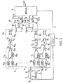
ここで図2を参照すると、プリフィルタリングステージ10および特徴抽出ステージ12は、より詳細に記載される。プリフィルタリングステージ10は、入力信号の高周波コンポーネントを増幅するハイパスフィルタである。プリフィルタリングステージ10は、1サンプル遅延素子21、乗算器23、および加算器24を含む。乗算器23は、典型的に−0.97の固定値を有する定数kfによって1サンプル遅延された信号を乗算する。プリフィルタリングステージ10の出力Xは、バンドパスフィルタ301、302、...30nのバンクにおけるサンプリングレートにおいて出力される。
Referring now to FIG. 2, the
一実施形態において、バンドパスフィルタ301、302、...30nは、近接した周波数バンドにおいて位置付けられる。図5のグラフ72において示されるように線形周波数スケール(「線形スケール」)68によってバンドパスフィルタ301、302、...30nの間隔があけられる。用語「線形周波数スケール」は、通常かつ従来の意味(すなわち、実際の周波数分割は不規則に間隔があけられる)に従って本明細書中に用いられる。複数の複素バンドパスフィルタ301、302、...30nは、ペアP1−2に分割される。ペア(P1またはP2)は、隣接した周波数バンドにそれぞれ2つの複素バンドパスフィルタ(301−2または303−4)を含む。全てのペア(P1またはP2)について、高周波数バンド(302または304)におけるフィルタの出力(「一次フィルタ」として以下に言及される)は、より低い周波数バンド(301または303)におけるフィルタの出力の共役によって乗算される(「二次フィルタ」として以下に言及される)。結果として生じる信号は、ロウパスフィルタリングされる。
In one embodiment, the bandpass filters 30 1 , 30 2 ,. . . 30 n is located in the adjacent frequency band. Bandpass filters 30 1 , 30 2 ,... By linear frequency scale (“linear scale”) 68 as shown in
バンドバスフィルタ301、302、...30nの数および周波数バンドの幅は、好適には、スピーチ処理システムのアプリケーションによって選択される。例えば、電話技術のアプリケーションに役立つシステムは、ほぼ100Hz離れた中心周波数を有する約40のバンドパスフィルタ301、302、...30nを利用する。例えば、フィルタ301は50Hzの中心周波数を有し、フィルタ302は150Hzの中心周波数を有し、フィルタ303は250Hzの中心周波数を有し得、ゆえに、フィルタ3040の中心周波数は3950Hzである。各フィルタのバンド幅は、数百ヘルツであり得る。
Band-
別の実施形態において、図6のグラフ70に示されるように、バンドパスフィルタ301、302、...30108は、例えば、対数的(または指数関数的)周波数スケール74(「対数スケール」)といった非線形周波数スケールによって構成される。用語対数的周波数は、通常かつ従来の意味によって本明細書中に用いられる。 In another embodiment, the bandpass filters 30 1 , 30 2 ,. . . 30 108 is configured with a non-linear frequency scale such as, for example, a logarithmic (or exponential) frequency scale 74 (“logarithmic scale”). The term logarithmic frequency is used herein in its usual and conventional sense.
経験的な証明は、図5の線形スケール68の代わりに図6の対数スケール74を用いることが音声認識性能を改良することを示唆する。すなわち、なぜなら、人間の耳は、音声スペクトルを超える周波数を非線形に消滅するからである。線形スケール68の代わりに対数スケールを用いる別の利点は、対数スケール74がさらなるバンドパスフィルタ301、302、...30nを用いることなく周波数スペクトルのより広い領域をカバーし得る。
Empirical evidence suggests that using the logarithmic scale 74 of FIG. 6 instead of the
バンドパスフィルタ301−108のペアP1−54は、対数スケール74によって間隔があけられる。ペアP1はフィルタ301および302を含み、ペアP10はフィルタ3019を含み、ペアP54はフィルタ30107および30108を含む。この構成において、フィルタ301、3020および30108は一次フィルタであり、フィルタ3019、および30107は二次フィルタである。
Pair P 1-54 of the band-pass filter 30 1-108, the interval by a logarithmic scale 74 is opened. Pair P 1 includes
1つの好適な実施形態において、一次フィルタ302、3020、...30108は、対数スケール74に沿った多様な周波数に中心があり、二次フィルタ301、303、...30107は、それぞれ、対応する一次フィルタ302、304、...30108 よりも100ヘルツ(Hz)だけ低いところに中心がある。図6のグラフ70を作成するために例示のMATLABコードは以下に示される。
In one preferred embodiment, the

一実施形態において、バンドパスフィルタ301−108は、三角形状である。別の実施形態において、バンドパスフィルタ301−108は、特定の音声認識システムの必要性による多様な形状であり得る。 In one embodiment, the bandpass filter 30 1-108 are triangular. In another embodiment, the bandpass filter 301-108 may have a variety of shapes depending on the needs of a particular speech recognition system.
対数スケール74は、0〜4000Hzの領域に示され得る。全てのペアP1−54に対して、一次フィルタ302、3020、...30108の出力は、二次フィルタ301、303、...30107の出力の共役によって乗算される。結果として生じる信号は、ロウパスフィルタリングされる。
A logarithmic scale 74 can be shown in the region of 0-4000 Hz. For all pairs P 1-54 , the
ペアP1−54は、高い周波数よりも低い周波数においてより多くのペアP1−54 を含むように構成される。例えば、500〜1000Hzの周波数領域において7つのペア(P16−22)があり、3000〜3500Hzの周波数領域において3つだけのペア(P49−51)がある。従って、より低い周波数においてオーバーサンプリングが実行されているが、より高い周波数において少なくともいくつかのサンプリングが実行されている。対数スケール74に沿ったペアP1−54の集中は、特定の音声認識システムの必要性によって変化され得る。 Pair P 1-54 is configured to include more pairs P 1-5 4 in lower frequencies than higher frequencies. For example, there are seven pairs (P 16-22 ) in the frequency region of 500-1000 Hz, and only three pairs (P 49-51 ) in the frequency region of 3000-3500 Hz. Thus, although oversampling is performed at a lower frequency, at least some of the sampling is performed at higher frequencies. The concentration of the pair P 1-54 along the logarithmic scale 74 can be varied depending on the needs of a particular speech recognition system.
デジタル信号処理設計の当業者に明らかであるように、前述の実施形態のバンドパスフィルタは、任意の多くのソフトウェアまたはハードウェア技術を用いてインプリメントされ得る。例えば、複数の複素フィルタは、高速フーリエ変換(FFT)、チャープZ変換、他の周波数ドメイン分析技術を用いてインプリメントされ得る。 As will be apparent to those skilled in the art of digital signal processing design, the bandpass filters of the previous embodiments can be implemented using any number of software or hardware techniques. For example, multiple complex filters may be implemented using Fast Fourier Transform (FFT), Chirp Z transform, other frequency domain analysis techniques.
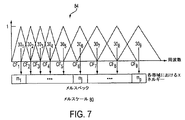
代替の実施形態において、図7に記載されるように、バンドパスフィルタ301、302、...30nは、例えば、メルスケールといった非線形周波数スケールによって構成される。メルスケール80は、音声認識システムの技術において周知であり、典型的に等式 In an alternative embodiment, as described in FIG. 7, the bandpass filters 30 1 , 30 2 ,. . . 30 n is configured by a non-linear frequency scale such as a mel scale, for example. Melscale 80 is well known in the art of speech recognition systems and is typically an equation.
図7は、メルスケール80によって間隔があけられたバンドパスフィルタ301−9を示すグラフ84の一実施形態を示す。中心周波数(CF1−9)は、上述の等式を用いることによって計算されるMel(f)値である。典型的に、フィルタ301−9は、ゼロからナイキスト(Nyquist)周波数までの全体の周波数領域に広がる。一実施形態において、フィルタ301−9は、同じバンド幅を有する。別の実施形態において、フィルタ301−9は異なるバンド幅を有し得る。
FIG. 7 shows one embodiment of a graph 84 showing
図8に記載される、さらに別の実施形態において、バンドパスフィルタ301−8は線形68および非線形74の周波数スケールの組み合わせによって間隔があけられる。バンドパスフィルタ301−4(P1−2)は、線形周波数68によって隣接した周波数バンドに構成される。
In yet another embodiment, described in FIG. 8, the bandpass filters 30 1-8 are spaced by a combination of linear 68 and nonlinear 74 frequency scales. The bandpass filters 30 1-4 (P 1-2 ) are configured in adjacent frequency bands by the
一次フィルタ306および308は、対数スケール74に沿って中心がある。二次フィルタ305および307は、306および308の中心周波数よりも100Hzだけ低い周波数に中心がある。これらのペア(P1またはP2)のそれぞれについて、一次フィルタ(306および308)の出力は、二次フィルタ(305および307)の出力の共役によってそれぞれ乗算され、結果的に生じる信号は、ロウパスフィルタリングされる。
図2を再度参照すると、ブロック401−20は、バンドパスフィルタ301、302、...30n−1の出力信号の複素共役を提供する。乗算器ブロック421−20は、近似のより高い周波数のバンドパスフィルタ302、304、306、...3040の出力によって複素共役を乗算する。つぎに、出力信号Z1−20は、一連のロウパスフィルタ441−22を通される。ロウパスフィルタの出力は、典型的に、特徴フレームレートにおいてのみ生成される。例えば、8kHzの入力スピーチサンプリングレートにおいて、ロウパスフィルタの出力は、10ミリ秒毎に1度の特徴フレームレートにおいて計算されるだけである。
Referring back to FIG. 2, blocks 40 1-20 include
ロウパスフィルタ441−22の各出力は、実数のコンポーネントRおよび虚数のコンポーネントIを有する複素信号である。ブロック461−20は、ロウパスフィルタ出力の実数および虚数のコンポーネントを処理し、等式(1)および(2)、 Each output of the low pass filter 44 1-22 is a complex signal having a real component R and an imaginary component I. Blocks 46 1-20 process the real and imaginary components of the low pass filter output, and equations (1) and (2),
次に、振幅信号A1−20および周波数信号F1−20は、例えば、離散コサイン変換、メルスケール変換、平均規格化、デルタおよび加速度分析、線形判別分析、ならびに、当該分野において本来公知である主要コンポーネント分析を用いて、特徴拡張コンポーネント12bにおける従来の特徴拡張技術を用いて処理される。本発明のスピーチ抽出システムに組み込む本発明のスピーチ認識システムの好適な実施形態は、本明細書中で以下に記載されるように、離散コサイン変換およびデルタ特徴技術を利用する。
Next, the amplitude signal A 1-20 and the frequency signal F 1-20 are known per se in the art, for example, discrete cosine transform, mel scale transform, average normalization, delta and acceleration analysis, linear discriminant analysis, and the like. Using the principal component analysis, it is processed using conventional feature enhancement techniques in the
さらに図2を参照すると、特徴拡張コンポーネント12bは、出力信号A1−20およびF1−20を受信し、それぞれ離散コサイン変換(DCT)ブロック50および54を用いてそれらの信号を処理する。DCT50および54は、信号A1−20およびF1−20の分散行列を対角化するように試みる。これは、DCT50の出力信号B0−19およびDCT54の出力信号C0−19における特徴を無相関するために役立つ。次に、出力信号B0−19およびC0−19の各セットは統計的な処理ステージ14に入力される。出力信号B0−19を提供するように入力信号A0−20上のDCT50によって実行される関数は等式(3)によって示され、出力信号C0−19を提供するように入力信号F1−20上のDCT54によって実行される関数は等式(4)によって示される。
Still referring to FIG. 2,
出力信号B0−19およびC0−19はまた、それぞれデルタブロック52および56に入力される。デルタブロック52および56のそれぞれは、連続する特徴フレーム間の特徴ベクトル値の測定間の差を取得し、この差がスピーチ認識性能を拡張するように用いられ得る。いくつかの差の式は、当該分野に公知であるように、デルタブロック52および56によって用いられ得る。例えば、デルタブロック52および56は、2つの連続する特徴フレーム間の差を取得し得る。デルタブロック52および56の出力信号は、統計処理ステージ14に入力される。
Output signals B 0-19 and C 0-19 are also input to delta blocks 52 and 56, respectively. Each of the delta blocks 52 and 56, obtains a difference between the measurement of a feature vector values between features consecutive frames, this difference can be used to extend the speech recognition performance. Several difference equations may be used by delta blocks 52 and 56 as is known in the art. For example, delta blocks 52 and 56 may obtain the difference between two successive feature frame. The output signals of the delta blocks 52 and 56 are input to the
式 formula
式(7)は、エネルギーブロック16が前のLサンプリング間隔(例えば、K=220、T=1/8000秒)の間の入力信号INの値の正方形の和を取得し、Kで和を割って、最終的な結果の対数を取得することを示す。エネルギーブロック16はフレーム毎(例えば、10ミリ秒)にこの計算を実行し、統計処理ブロック14に入力としての結果を提供する。
Equation (7) obtains the square sum of the values of the input signal IN during the previous L sampling interval (eg, K = 220, T = 1/8000 seconds) and the
ここで、図3を参照すると、本発明の特徴抽出システムにおける使用に適した例示の複素バンドパスフィルタ30’が記載される。フィルタ30’は、加算器31、乗算器32、および1サンプル遅延素子33を含む。乗算器32は、1サンプル遅延出力Yに複素係数Gを掛けて、結果として、入力信号Xに足されて、出力信号Yを生成する。
Referring now to FIG. 3, an exemplary complex bandpass filter 30 'suitable for use in the feature extraction system of the present invention is described. The
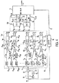
本発明の特徴抽出システムの代替の実施形態は、図4に関して記載される。図4の実施形態は、図2の実施形態に類似しており、フィルタリングステージ10、統計処理ステージ14、およびエネルギーステージ16を含み、上述されるように実質的に動作する。しかし、図4の実施形態は、特徴抽出ステージ12’が特徴抽出システム12a’内でさらなる回路部を含むという前述される実施形態とは異なり、特徴ベクトルはさらなる情報を含む。
An alternative embodiment of the feature extraction system of the present invention is described with respect to FIG. The embodiment of FIG. 4 is similar to the embodiment of FIG. 2 and includes a
例えば、特徴抽出ステージ12a’は、バンドパスフィルタ301−41のバンクおよび共役ブロック401−40を含む。各バンドパスフィルタの出力は、乗算器421−40によるより低い隣接したバンドパスフィルタの出力の共役と組み合わされ、計算ブロック461−40は、ベクトルが20の代わりに40の素子の長さを有することを除いて、上述されるようにベクトルAおよびFを計算する。DCT50および54、ならびに、特徴拡張コンポーネント12b’のデルタブロック52および56は、40の素子入力ベクトルを承認して、40の素子ベクトルを統計処理ブロック14に出力する。バンドパスフィルタ301−41が例えば対数スケールまたはメルスケールといった非線型周波数スケールによって構成される場合、図4に示される構成は適用できないことは理解される。
For example, the
本発明は、意図された音声処理アプリケーションによってバンドパスフィルタ30の任意の数、ならびに、共役ブロック40、乗算器42、ロウパスフィルタ44、およびブロック46の対応する数を含み、各ロウパスフィルタの出力信号AおよびFを提供し得る。特徴抽出ステージを含む。さらに、信号AおよびFは、重み付された様態で組み合わされ得、信号の一部のみが使用され得る。例えば、一周波数ドメインにおける振幅信号、ならびに、別の周波数ドメインにおける振幅と周波数との組み合わせのみを用いることは利点があり得る。
The present invention includes any number of
本発明の好適な例示の実施形態が上述され、多様な変化および変更が本発明から逸脱することなくなされることは、当業者によって理解され、本発明の実際の意図および範囲内に含まれるような全ての変化および変更をカバーすることが、添付の特許請求の範囲において意図される。 It will be understood by those skilled in the art that various exemplary changes and modifications can be made without departing from the invention, and are included within the actual spirit and scope of the invention, as preferred exemplary embodiments of the invention are described above. It is intended in the appended claims to cover all such changes and modifications.
Claims (38)
該装置は、
該入力発話信号を受信するように適合された第1および第2のバンドパスフィルタであって、該第1のバンドパスフィルタは、第1の信号を提供し、該第2のバンドパスフィルタは、第2の信号を提供し、該第1のバンドパスフィルタおよび該第2のバンドパスフィルタは、隣接した周波数帯域を有する、第1および第2のバンドパスフィルタと、
該第2のバンドパスフィルタに接続された共役回路であって、該第2の信号の共役である第3の信号を提供する共役回路と、
該第1のバンドパスフィルタおよび該共役回路に接続された乗算器であって、該第1の信号と該第3の信号との積である第4の信号を提供する乗算器と、
該乗算器に接続されたフィルタ手段であって、該第4の信号をフィルタリングして、該入力発話信号の該周波数特徴に対応する第5の信号と、該入力発話信号の該振幅特徴に対応する第6の信号とを出力するフィルタ手段と
を備える、装置。An apparatus for extracting features from an input speech signal having frequency features and amplitude features,
The device
First and second bandpass filters adapted to receive the input speech signal, wherein the first bandpass filter provides a first signal and the second bandpass filter comprises: Providing a second signal, the first bandpass filter and the second bandpass filter having adjacent frequency bands; and
A conjugate circuit connected to the second bandpass filter for providing a third signal that is a conjugate of the second signal;
A multiplier connected to the first bandpass filter and the conjugate circuit for providing a fourth signal that is a product of the first signal and the third signal;
Filter means connected to the multiplier for filtering the fourth signal and corresponding to the fifth signal corresponding to the frequency characteristic of the input speech signal and the amplitude characteristic of the input speech signal And a filter means for outputting a sixth signal.
算する、請求項5に記載の装置。The adder receives the input utterance signal and outputs an output signal, and the adder adds the input utterance signal and a signal including a delayed sample of the output signal multiplied by a complex coefficient. The apparatus according to claim 5.
該電気信号をデジタル信号に変換するサンプラーと
をさらに備え、前記入力発話信号は、該デジタル信号を含む、請求項1に記載の装置。A transducer that converts sound into an electrical signal;
The apparatus according to claim 1, further comprising: a sampler that converts the electrical signal into a digital signal, wherein the input speech signal includes the digital signal.
該方法は、
第1のバンドパスフィルタと第2のバンドパスフィルタとを用いて、該入力発話信号を、第1の周波数帯域における第1の信号と第2の周波数帯域における第2の信号とに分離することであって、該第1のバンドパスフィルタおよび該第2のバンドパスフィルタは、隣接した周波数帯域を有する、ことと、
共役回路を用いて該第2の信号の共役をとることと、
乗算器を用いて該第2の信号の該共役と該第1の信号とを乗算することにより、第3の信号を提供することと、
フィルタ手段を用いて該第3の信号を処理することにより、該入力発話信号における周波数特徴に対応する周波数成分と、該入力発話信号における振幅特徴に対応する振幅成分とを生成することと
を包含する、方法。A method for extracting features from an input speech signal,
The method
Separating the input speech signal into a first signal in the first frequency band and a second signal in the second frequency band using a first bandpass filter and a second bandpass filter. The first bandpass filter and the second bandpass filter have adjacent frequency bands;
Taking the conjugate of the second signal using a conjugate circuit;
Providing a third signal by multiplying the conjugate of the second signal by the first signal using a multiplier;
Generating a frequency component corresponding to the frequency feature in the input speech signal and an amplitude component corresponding to the amplitude feature in the input speech signal by processing the third signal using a filter means. how to.
サンプラーを用いて該電気信号をサンプリングすることにより、デジタル信号を提供することと
をさらに包含し、前記入力発話信号は、該デジタル信号を含む、請求項23に記載の方法。And converting the electrodeposition No. relaxin sound using a transducer,
24. The method of claim 23, further comprising: providing a digital signal by sampling the electrical signal using a sampler, and wherein the input speech signal comprises the digital signal.
Applications Claiming Priority (2)
| Application Number | Priority Date | Filing Date | Title |
|---|---|---|---|
| US09/882,744 US6493668B1 (en) | 2001-06-15 | 2001-06-15 | Speech feature extraction system |
| PCT/US2002/019182 WO2002103676A1 (en) | 2001-06-15 | 2002-06-14 | Speech feature extraction system |
Publications (3)
| Publication Number | Publication Date |
|---|---|
| JP2004531767A JP2004531767A (en) | 2004-10-14 |
| JP2004531767A5 JP2004531767A5 (en) | 2008-04-17 |
| JP4177755B2 true JP4177755B2 (en) | 2008-11-05 |
Family
ID=25381249
Family Applications (1)
| Application Number | Title | Priority Date | Filing Date |
|---|---|---|---|
| JP2003505912A Expired - Fee Related JP4177755B2 (en) | 2001-06-15 | 2002-06-14 | Utterance feature extraction system |
Country Status (7)
| Country | Link |
|---|---|
| US (2) | US6493668B1 (en) |
| EP (1) | EP1402517B1 (en) |
| JP (1) | JP4177755B2 (en) |
| AT (1) | ATE421137T1 (en) |
| CA (1) | CA2450230A1 (en) |
| DE (1) | DE60230871D1 (en) |
| WO (1) | WO2002103676A1 (en) |
Families Citing this family (37)
| Publication number | Priority date | Publication date | Assignee | Title |
|---|---|---|---|---|
| JP3673507B2 (en) * | 2002-05-16 | 2005-07-20 | 独立行政法人科学技術振興機構 | APPARATUS AND PROGRAM FOR DETERMINING PART OF SPECIFIC VOICE CHARACTERISTIC CHARACTERISTICS, APPARATUS AND PROGRAM FOR DETERMINING PART OF SPEECH SIGNAL CHARACTERISTICS WITH HIGH RELIABILITY, AND Pseudo-Syllable Nucleus Extraction Apparatus and Program |
| JP4265908B2 (en) * | 2002-12-12 | 2009-05-20 | アルパイン株式会社 | Speech recognition apparatus and speech recognition performance improving method |
| DE102004008225B4 (en) * | 2004-02-19 | 2006-02-16 | Infineon Technologies Ag | Method and device for determining feature vectors from a signal for pattern recognition, method and device for pattern recognition and computer-readable storage media |
| US20070041517A1 (en) * | 2005-06-30 | 2007-02-22 | Pika Technologies Inc. | Call transfer detection method using voice identification techniques |
| US20070118364A1 (en) * | 2005-11-23 | 2007-05-24 | Wise Gerald B | System for generating closed captions |
| US20070118372A1 (en) * | 2005-11-23 | 2007-05-24 | General Electric Company | System and method for generating closed captions |
| US8345890B2 (en) | 2006-01-05 | 2013-01-01 | Audience, Inc. | System and method for utilizing inter-microphone level differences for speech enhancement |
| US8194880B2 (en) | 2006-01-30 | 2012-06-05 | Audience, Inc. | System and method for utilizing omni-directional microphones for speech enhancement |
| US8204252B1 (en) | 2006-10-10 | 2012-06-19 | Audience, Inc. | System and method for providing close microphone adaptive array processing |
| US8744844B2 (en) | 2007-07-06 | 2014-06-03 | Audience, Inc. | System and method for adaptive intelligent noise suppression |
| US9185487B2 (en) | 2006-01-30 | 2015-11-10 | Audience, Inc. | System and method for providing noise suppression utilizing null processing noise subtraction |
| US7778831B2 (en) * | 2006-02-21 | 2010-08-17 | Sony Computer Entertainment Inc. | Voice recognition with dynamic filter bank adjustment based on speaker categorization determined from runtime pitch |
| US8204253B1 (en) | 2008-06-30 | 2012-06-19 | Audience, Inc. | Self calibration of audio device |
| US20080010067A1 (en) * | 2006-07-07 | 2008-01-10 | Chaudhari Upendra V | Target specific data filter to speed processing |
| US8259926B1 (en) | 2007-02-23 | 2012-09-04 | Audience, Inc. | System and method for 2-channel and 3-channel acoustic echo cancellation |
| US8189766B1 (en) | 2007-07-26 | 2012-05-29 | Audience, Inc. | System and method for blind subband acoustic echo cancellation postfiltering |
| US9269372B2 (en) * | 2007-08-27 | 2016-02-23 | Telefonaktiebolaget L M Ericsson (Publ) | Adaptive transition frequency between noise fill and bandwidth extension |
| US20090150164A1 (en) * | 2007-12-06 | 2009-06-11 | Hu Wei | Tri-model audio segmentation |
| US8180064B1 (en) | 2007-12-21 | 2012-05-15 | Audience, Inc. | System and method for providing voice equalization |
| US8194882B2 (en) | 2008-02-29 | 2012-06-05 | Audience, Inc. | System and method for providing single microphone noise suppression fallback |
| US8355511B2 (en) | 2008-03-18 | 2013-01-15 | Audience, Inc. | System and method for envelope-based acoustic echo cancellation |
| US8521530B1 (en) | 2008-06-30 | 2013-08-27 | Audience, Inc. | System and method for enhancing a monaural audio signal |
| US8626516B2 (en) * | 2009-02-09 | 2014-01-07 | Broadcom Corporation | Method and system for dynamic range control in an audio processing system |
| US9838784B2 (en) | 2009-12-02 | 2017-12-05 | Knowles Electronics, Llc | Directional audio capture |
| US9008329B1 (en) | 2010-01-26 | 2015-04-14 | Audience, Inc. | Noise reduction using multi-feature cluster tracker |
| US9142220B2 (en) | 2011-03-25 | 2015-09-22 | The Intellisis Corporation | Systems and methods for reconstructing an audio signal from transformed audio information |
| US8620646B2 (en) | 2011-08-08 | 2013-12-31 | The Intellisis Corporation | System and method for tracking sound pitch across an audio signal using harmonic envelope |
| US8548803B2 (en) * | 2011-08-08 | 2013-10-01 | The Intellisis Corporation | System and method of processing a sound signal including transforming the sound signal into a frequency-chirp domain |
| US9183850B2 (en) | 2011-08-08 | 2015-11-10 | The Intellisis Corporation | System and method for tracking sound pitch across an audio signal |
| US8781880B2 (en) | 2012-06-05 | 2014-07-15 | Rank Miner, Inc. | System, method and apparatus for voice analytics of recorded audio |
| US9536540B2 (en) | 2013-07-19 | 2017-01-03 | Knowles Electronics, Llc | Speech signal separation and synthesis based on auditory scene analysis and speech modeling |
| US9280968B2 (en) * | 2013-10-04 | 2016-03-08 | At&T Intellectual Property I, L.P. | System and method of using neural transforms of robust audio features for speech processing |
| WO2016040885A1 (en) | 2014-09-12 | 2016-03-17 | Audience, Inc. | Systems and methods for restoration of speech components |
| US9922668B2 (en) | 2015-02-06 | 2018-03-20 | Knuedge Incorporated | Estimating fractional chirp rate with multiple frequency representations |
| US9870785B2 (en) | 2015-02-06 | 2018-01-16 | Knuedge Incorporated | Determining features of harmonic signals |
| US9842611B2 (en) | 2015-02-06 | 2017-12-12 | Knuedge Incorporated | Estimating pitch using peak-to-peak distances |
| US9820042B1 (en) | 2016-05-02 | 2017-11-14 | Knowles Electronics, Llc | Stereo separation and directional suppression with omni-directional microphones |
Family Cites Families (4)
| Publication number | Priority date | Publication date | Assignee | Title |
|---|---|---|---|---|
| US4300229A (en) * | 1979-02-21 | 1981-11-10 | Nippon Electric Co., Ltd. | Transmitter and receiver for an othogonally multiplexed QAM signal of a sampling rate N times that of PAM signals, comprising an N/2-point offset fourier transform processor |
| US4221934A (en) * | 1979-05-11 | 1980-09-09 | Rca Corporation | Compandor for group of FDM signals |
| GB8307702D0 (en) * | 1983-03-21 | 1983-04-27 | British Telecomm | Digital band-split filter means |
| NL8400677A (en) * | 1984-03-02 | 1985-10-01 | Philips Nv | TRANSMISSION SYSTEM FOR THE TRANSMISSION OF DATA SIGNALS IN A MODULAR TIRE. |
-
2001
- 2001-06-15 US US09/882,744 patent/US6493668B1/en not_active Expired - Lifetime
-
2002
- 2002-06-14 JP JP2003505912A patent/JP4177755B2/en not_active Expired - Fee Related
- 2002-06-14 US US10/173,247 patent/US7013274B2/en not_active Expired - Lifetime
- 2002-06-14 AT AT02744395T patent/ATE421137T1/en not_active IP Right Cessation
- 2002-06-14 CA CA002450230A patent/CA2450230A1/en not_active Abandoned
- 2002-06-14 WO PCT/US2002/019182 patent/WO2002103676A1/en active Application Filing
- 2002-06-14 EP EP02744395A patent/EP1402517B1/en not_active Expired - Lifetime
- 2002-06-14 DE DE60230871T patent/DE60230871D1/en not_active Expired - Lifetime
Also Published As
| Publication number | Publication date |
|---|---|
| US6493668B1 (en) | 2002-12-10 |
| EP1402517A4 (en) | 2007-04-25 |
| ATE421137T1 (en) | 2009-01-15 |
| CA2450230A1 (en) | 2002-12-27 |
| JP2004531767A (en) | 2004-10-14 |
| US20020198711A1 (en) | 2002-12-26 |
| US20030014245A1 (en) | 2003-01-16 |
| DE60230871D1 (en) | 2009-03-05 |
| EP1402517B1 (en) | 2009-01-14 |
| EP1402517A1 (en) | 2004-03-31 |
| US7013274B2 (en) | 2006-03-14 |
| WO2002103676A1 (en) | 2002-12-27 |
Similar Documents
| Publication | Publication Date | Title |
|---|---|---|
| JP4177755B2 (en) | Utterance feature extraction system | |
| JP2004531767A5 (en) | ||
| US6804643B1 (en) | Speech recognition | |
| Sailor et al. | Auditory Filterbank Learning for Temporal Modulation Features in Replay Spoof Speech Detection. | |
| EP1580730A2 (en) | Isolating speech signals utilizing neural networks | |
| Kim et al. | Nonlinear enhancement of onset for robust speech recognition. | |
| CN102054480A (en) | Method for separating monaural overlapping speeches based on fractional Fourier transform (FrFT) | |
| US5806022A (en) | Method and system for performing speech recognition | |
| CN112382300A (en) | Voiceprint identification method, model training method, device, equipment and storage medium | |
| Wang et al. | Low pass filtering and bandwidth extension for robust anti-spoofing countermeasure against codec variabilities | |
| Maazouzi et al. | MFCC and similarity measurements for speaker identification systems | |
| KR100571427B1 (en) | Feature Vector Extraction Unit and Inverse Correlation Filtering Method for Speech Recognition in Noisy Environments | |
| CN116312561A (en) | Method, system and device for voice print recognition, authentication, noise reduction and voice enhancement of personnel in power dispatching system | |
| CN110767238B (en) | Blacklist identification method, device, equipment and storage medium based on address information | |
| JP7184236B2 (en) | Voiceprint Recognition Method, Apparatus, Equipment, and Storage Medium | |
| JP3916834B2 (en) | Extraction method of fundamental period or fundamental frequency of periodic waveform with added noise | |
| Rosell | An introduction to front-end processing and acoustic features for automatic speech recognition | |
| Lalitha et al. | An encapsulation of vital non-linear frequency features for various speech applications | |
| JPS6229799B2 (en) | ||
| KR100381372B1 (en) | Apparatus for feature extraction of speech signals | |
| KR100563316B1 (en) | Method and Apparatus for Feature Vector Generation using a Supplementary Feature | |
| CN117079666A (en) | Song scoring method, song scoring device, terminal equipment and storage medium | |
| Niyozmatova et al. | Development Software for Preprocessing Voice Signals | |
| JP4014374B2 (en) | Voice analysis method | |
| Kalamani et al. | Comparison Of Cepstral And Mel Frequency Cepstral Coefficients For Various Clean And Noisy Speech Signals |
Legal Events
| Date | Code | Title | Description |
|---|---|---|---|
| A621 | Written request for application examination |
Free format text: JAPANESE INTERMEDIATE CODE: A621 Effective date: 20050613 |
|
| A131 | Notification of reasons for refusal |
Free format text: JAPANESE INTERMEDIATE CODE: A131 Effective date: 20071031 |
|
| A601 | Written request for extension of time |
Free format text: JAPANESE INTERMEDIATE CODE: A601 Effective date: 20080130 |
|
| A602 | Written permission of extension of time |
Free format text: JAPANESE INTERMEDIATE CODE: A602 Effective date: 20080206 |
|
| A524 | Written submission of copy of amendment under article 19 pct |
Free format text: JAPANESE INTERMEDIATE CODE: A524 Effective date: 20080227 |
|
| A131 | Notification of reasons for refusal |
Free format text: JAPANESE INTERMEDIATE CODE: A131 Effective date: 20080402 |
|
| A521 | Request for written amendment filed |
Free format text: JAPANESE INTERMEDIATE CODE: A523 Effective date: 20080603 |
|
| TRDD | Decision of grant or rejection written | ||
| A01 | Written decision to grant a patent or to grant a registration (utility model) |
Free format text: JAPANESE INTERMEDIATE CODE: A01 Effective date: 20080801 |
|
| A01 | Written decision to grant a patent or to grant a registration (utility model) |
Free format text: JAPANESE INTERMEDIATE CODE: A01 |
|
| A61 | First payment of annual fees (during grant procedure) |
Free format text: JAPANESE INTERMEDIATE CODE: A61 Effective date: 20080822 |
|
| FPAY | Renewal fee payment (event date is renewal date of database) |
Free format text: PAYMENT UNTIL: 20110829 Year of fee payment: 3 |
|
| R150 | Certificate of patent or registration of utility model |
Free format text: JAPANESE INTERMEDIATE CODE: R150 |
|
| FPAY | Renewal fee payment (event date is renewal date of database) |
Free format text: PAYMENT UNTIL: 20110829 Year of fee payment: 3 |
|
| FPAY | Renewal fee payment (event date is renewal date of database) |
Free format text: PAYMENT UNTIL: 20120829 Year of fee payment: 4 |
|
| FPAY | Renewal fee payment (event date is renewal date of database) |
Free format text: PAYMENT UNTIL: 20130829 Year of fee payment: 5 |
|
| R250 | Receipt of annual fees |
Free format text: JAPANESE INTERMEDIATE CODE: R250 |
|
| R250 | Receipt of annual fees |
Free format text: JAPANESE INTERMEDIATE CODE: R250 |
|
| R250 | Receipt of annual fees |
Free format text: JAPANESE INTERMEDIATE CODE: R250 |
|
| R250 | Receipt of annual fees |
Free format text: JAPANESE INTERMEDIATE CODE: R250 |
|
| R250 | Receipt of annual fees |
Free format text: JAPANESE INTERMEDIATE CODE: R250 |
|
| LAPS | Cancellation because of no payment of annual fees |