JP3615136B2 - Digital video information device with continuous image capture function - Google Patents
Digital video information device with continuous image capture function Download PDFInfo
- Publication number
- JP3615136B2 JP3615136B2 JP2000284177A JP2000284177A JP3615136B2 JP 3615136 B2 JP3615136 B2 JP 3615136B2 JP 2000284177 A JP2000284177 A JP 2000284177A JP 2000284177 A JP2000284177 A JP 2000284177A JP 3615136 B2 JP3615136 B2 JP 3615136B2
- Authority
- JP
- Japan
- Prior art keywords
- information
- video
- recording
- still image
- unit
- Prior art date
- Legal status (The legal status is an assumption and is not a legal conclusion. Google has not performed a legal analysis and makes no representation as to the accuracy of the status listed.)
- Expired - Fee Related
Links
Images


Landscapes
- Signal Processing For Digital Recording And Reproducing (AREA)
- Management Or Editing Of Information On Record Carriers (AREA)
- Television Signal Processing For Recording (AREA)
Description
【0001】
【発明の属する技術分野】
この発明は、静止画の連続取り込み機能を備えたデジタル映像情報装置に関する。
【0002】
【従来の技術】
現在、ビデオ(動画映像)のデジタル記録/再生にMPEG2(ムービングピクチャエキスパートグループ2)方式を利用し、オーディオ(音声)のデジタル記録/再生にACー3(デジタルオーディオコンプレッション3)方式等を利用したDVDビデオ規格がまとまり、この規格を利用した種々な再生機器(DVDビデオプレーヤ)が市販されている。
【0003】
このDVDビデオ規格は、MPEG2システムレイヤに従って、動画圧縮方式としてはMPEG2、音声記録方式としてはリニアPCMの他にACー3オーディオおよびMPEGオーディオをサポートしている。また、このDVDビデオ規格は、字幕用に副映像データ、早送り巻き戻しデータサーチ等の再生制御用にナビゲーションデータ、コンピュータ対応用にISO9660およびUDFブリッジフォーマットもサポートしている。
【0004】
さらに、書込可能なDVDディスク(リード・ライト可能なDVD−RAM、書替可能なDVD−RW、あるいはライトワンスのDVD−R)の開発もなされ、書込可能DVDディスクを利用したデジタル映像情報の記録再生機器(従来のアナログビデオカセットレコーダに取って代わるデジタルビデオディスクレコーダ)の開発が可能な環境ができ上がっている。
【0005】
以上の状況から、リアルタイムでビデオ映像等のデジタル記録・再生を行うため、DVD用のリアルタイムレコーディング規格(RTR−DVD規格)が提案され、正式の規格としてまとまりつつある。このRTR−DVD規格は、正式規格として既にマーケットに受け入れられているDVDビデオ規格を元に考えられており、このRTR−DVD規格に対応したファイルシステムも現在規格化進行中である。
【0006】
【発明が解決しようとする課題】
ところで、RTR−DVD規格では、静止画(スチルピクチャ)を、最大63936枚(=スチルセルの最大数999×ビデオオブジェクトグループ内の最大枚数64)記録できる。この静止画のソースとしては、電子スチルカメラ(デジタルカメラ)などが考えられる。この電子スチルカメラでは、撮影した静止画の記録媒体としてICカードなどの半導体メモリが使用されている。
【0007】
一方、RTR−DVDビデオレコーダには光ディスクなどのディスク媒体が使用される。すなわち、電子スチルカメラとRTR−DVDビデオレコーダとでは使用する記録媒体が違う。このため、電子スチルカメラで作成した静止画データをRTR−DVDビデオレコーダに直接取り込むことは簡単ではない。
【0008】
また、ビデオ信号(通常の動画ビデオ信号、あるいは電子スチルカメラもしくはデジタルビデオムービーで作成した複数静止画群を含むビデオ信号)から複数の静止画を取り込む場合においても、映像内容が変わる度にユーザが1枚1枚の取り込み静止画を選択・設定しなければならず、非常に手間がかかるという問題点がある。
【0009】
この発明は上記事情に鑑みなされたもので、ユーザが1枚1枚の取り込み静止画を逐一選択・設定しなくても、ビデオ信号から複数静止画を連続的に取り込むことができる静止画連続取込機能付きデジタル映像情報装置を提供することを目的とする。
【0010】
この発明の他の目的は、ユーザが1枚1枚の取り込み静止画を逐一選択・設定しなくても、ビデオ信号から複数静止画を連続的に取り込んで記録する複数静止画記録方法を提供することである。
【0011】
【課題を解決するための手段】
上記目的を達成するために、この発明に係るデジタル映像情報装置は、静止画連続取り込みモードを指定するキー入力部(607)と;この静止画連続取り込みモードに移行後、入力されたビデオ信号より、取り込んだフレームが前のフレームと映像内容が違うことを検知するフレーム変化検知部(604)と;この検知部からの情報を元に、取り込んだフレームデータをMPEGのIピクチャに圧縮し、RTR−DVD規格で指定されているパック構造を生成するエンコーダ部(601)と;このエンコーダ部で生成されたIピクチャに関する情報から再生管理情報(S_VOG_GI)を作成する再生管理情報作成部(604)とにより構成されている。
【0012】
また、上記他の目的を達成するために、この発明に係る複数静止画記録方法では、所定枚数(64枚)以内の複数静止画の静止画グループ(VOG)を設定し(図14のST114;図18のST214);前記映像情報の録画開始後(図14のST116イエス;図18のST216イエス)、前記映像情報に含まれる前記複数静止画の記録を前記情報媒体(100)の前記データ記録エリアに対して連続的に行い(図14のST118を含む録画処理ループ;図18のST218を含む録画処理ループ);記録された前記複数静止画を、前記静止画グループ(VOG)毎にまとめる管理情報(VOG情報;図13のS_VOG_GI)を作成し(図14のST120;図19のST220);前記複数静止画の記録が行われた前記情報媒体(100)の管理情報記録エリア(VMG/S_AVFIT)に、前記作成された管理情報(S_VOG_GI)を書き込む(図14のST140;図20のST140)ようにしている。
【0013】
こうすることで、スライドショーのように連続再生される複数の静止画を含むビデオ信号から複数静止画を自動的に連続的に取り込み、RTR−DVDフォーマットで記録するシステムを構築することができる。
【0014】
【発明の実施の形態】
以下、図面を参照して、この発明の一実施の形態に係る静止画連続取込機能付きデジタル映像情報装置を説明する。
【0015】
図1は、この発明の一実施の形態に係る静止画連続取込機能付きデジタル映像情報装置(RTR−DVDビデオレコーダ)の全体構成を説明するブロック図である。
【0016】
図1に示すRTR−DVDビデオレコーダの装置本体は、大まかにいって、DVDーRAM、DVD−RWまたはDVDーR等の録再可能光ディスク100を回転駆動し、このディスク100に対して情報の読み書きを実行するディスクドライブ部609と、録画側を構成するエンコーダ部601と、再生側を構成するデコーダ部602と、装置全体の動作を制御するメインMPU部604とで構成されている。
【0017】
さらに、ディスクドライブ部609とメインMPU部604とを結ぶデータバスには、大容量(たとえば30GB〜100GBあるいはそれ以上)で高速な(データ転送レートがIEEE1394シリアルバスと同等以上;具体的には400Mpbs〜500Mbpsクラス)ハードディスクドライブ(HDD)を利用したレコーダユニット700を接続しておくことができる。
【0018】
この大容量高速HDDレコーダユニット700は、この発明の実施の形態によっては必ずしも必要ではないが、DVD−RAM等のディスクドライブ部609とHDDレコーダユニット700とを一体化しておくと、たとえば以下のようなことが可能になる。
【0019】
すなわち、TV放送番組等をHDDレコーダユニット700でエアチェックする。エアチェックした番組のうち、ユーザが消したくないと思う番組(コピー制限がされていない番組コンテンツ)が幾つかあれば、それらを適宜繋ぎ編集設定した後、DVD−RAMディスク、DVD−RWディスク、あるいはDVD−Rディスクにコピー(バックアップ)する。すると、HDDレコーダユニット700でエアチェックした所望番組の永久保存が可能となり、その一方で、ディスクにコピーした分をHDDレコーダユニット700から消去可能にできる(コピーした番組のファイルをごみ箱アイコンに捨てるなど)。そうすれば、ごみ箱アイコンに捨てたファイルサイズ分だけ、HDDレコーダユニット700に、その後の録画スペースを余分に確保できるようになる。
【0020】
あるいは、たとえば4.7GB容量のDVD−RAMディスク1枚に収まりきらない長時間TV番組のエアチェックは大容量(空き容量がたとえば30GB)HDDレコーダユニット700で行い、エアチェックした長時間番組を後にHDDレコーダユニット700から複数枚のDVD−RAMディスクにコピーすることもできる。このようにすれば、ディスク交換(あるいは録画用ディスクの切替)に要する期間中(数秒〜数十秒程度)に生じるエアチェック漏れを防止できる。
【0021】
あるいは、HDDレコーダユニット700にDVD−VRビデオ信号、DVD−ARオーディオ信号、DVD−SRストリーム信号を任意に混在記録しておく。そして、後に、HDDレコーダユニット700からDVD−VRビデオ信号だけをあるDVD−RAMディスクにコピーし、DVD−ARオーディオ信号だけを他のDVD−RAMディスクにコピーし、DVD−SRストリーム信号だけをさらに他のDVD−RAMディスクにコピーする、といったこともできる。
【0022】
なお、図1の装置にHDDレコーダユニット700を内蔵せず、この装置を光ディスクレコーダ専用の構成とし、この装置にHDDレコーダユニット700接続用のIEEE1394インターフェイス(あるいはHDDレコーダユニットを後に装着するためのスペースとその接続スロット)を設けるようにしてもよい。
【0023】
図1のエンコーダ部601は、A/D変換部614と、ビデオエンコード部616と、オーディオエンコード部617と、副映像(SP)エンコード部618と、フォーマッタ部619と、バッファメモリ部620とを備えている。
【0024】
A/D変換部614には、AV入力部612からの外部アナログビデオ信号+外部アナログオーディオ信号、あるいはTVチューナ部613からのアナログTV信号+アナログ音声信号等が入力される。このA/D変換部614は、入力されたアナログビデオ信号を、たとえばサンプリング周波数13.5MHz、量子化ビット数8ビットでデジタル化する。同様に、A/D変換部614は、入力されたアナログオーディオ信号を、たとえばサンプリング周波数48kHz、量子化ビット数16ビットでデジタル化する。
【0025】
なお、A/D変換部614にアナログビデオ信号およびデジタルオーディオ信号が入力されるときは、A/D変換部614はデジタルオーディオ信号をスルーパスさせる。一方、A/D変換部614にデジタルビデオ信号およびデジタルオーディオ信号が入力されるときは、A/D変換部614はデジタルビデオ信号およびデジタルオーディオ信号をスルーパスさせる。
【0026】
A/D変換部614からのデジタルビデオ信号成分は、ビデオエンコード部616を介してフォーマッタ部619に送られる。また、A/D変換部614からのデジタルオーディオ信号成分は、オーディオエンコード部617を介してフォーマッタ部619に送られる。
【0027】
ビデオエンコード部616は、入力されたデジタルビデオ信号を、MPEG2(またはMPEG1)規格に基づき、可変ビットレートで圧縮されたデジタル信号に変換する機能を持つ。また、オーディオエンコード部617は、入力されたデジタルオーディオ信号を、MPEGまたはAC−3規格に基づき、固定ビットレートで圧縮されたデジタル信号(またはリニアPCMのデジタル信号)に変換する機能を持つ。
【0028】
DVDビデオ信号がAV入力部612から入力された場合、あるいはDVDビデオ信号が放送されそれがTVチューナ部613で受信された場合は、DVDビデオ信号中の文字放送信号成分(あるいはクローズドキャプションCC)が、SPエンコード部618に入力される。SPエンコード部618に入力された副映像データは、所定の信号形態にアレンジされて、フォーマッタ部619に送られる。
【0029】
フォーマッタ部619は、バッファメモリ部620をワークエリアとして使用しながら、入力されたビデオ信号、オーディオ信号、副映像信号等に対して所定の信号処理を行い、所定のフォーマット(ファイル構造)に合致した記録データをデータプロセサ部(D−PRO部)610に出力する。
【0030】
ここで、上記記録データを作成するための標準的なエンコード処理内容を簡単に説明しておく。すなわち、図1のエンコーダ部601においてエンコード処理が開始されると、ビデオデータその他のエンコードにあたって必要なパラメータが設定される。次に、設定されたパラメータを利用して主映像データがプリエンコードされ、設定された平均転送レート(記録レート)に最適な符号量の分配が計算される。こうしてプリエンコードで得られた符号量分配に基づき、主映像のエンコードが実行される。このとき、オーディオデータのエンコードも同時に実行される。
【0031】
プリエンコードの結果、データ圧縮量が不十分な場合(録画しようとするDVDーRAMディスク、DVD−RWディスク、DVDーRディスク、またはHDDレコーダユニット700に希望のビデオプログラムが収まり切らない場合)、再度プリエンコードする機会を持てるなら(たとえば録画のソースがビデオテープあるいはビデオディスクなどの反復再生可能なソースであれば)、主映像データの部分的な再エンコードが実行され、再エンコードした部分の主映像データがそれ以前にプリエンコードした主映像データ部分と置換される。このような一連の処理によって、主映像データおよびオーディオデータがエンコードされ、記録に必要な平均ビットレートの値が、大幅に低減される。
【0032】
同様に、副映像データをエンコードするに必要なパラメータが設定され、エンコードされた副映像データが作成される。
【0033】
以上のようにしてエンコードされた主映像データ、オーディオデータおよび副映像データが組み合わされて、RTR−DVDビデオの構造に変換される。
【0034】
エンコードされた主映像データ、オーディオデータおよび副映像データは、図3の下段に示すような一定サイズ(2048バイト)のパックに細分化される。これらのパックには、図示しないダミーパックが適宜挿入される。なお、ダミーパック以外のパック内には、適宜、PTS(プレゼンテーションタイムスタンプ)、DTS(デコードタイムスタンプ)等のタイムスタンプが記述される。副映像のPTSについては、同じ再生時間帯の主映像データあるいはオーディオデータのPTSより任意に遅延させた時間を記述することができる。
【0035】
そして、各データのタイムコード順に再生可能なように、ビデオオブジェクトユニット(VOBU)単位で各データセルが配置されて、複数のセルで構成されるVOBが構成される。このVOBを1以上まとめたVR_MOVIE.VROファイル、VR_STILL.VROファイル、VR_AUDIO.VROファイル等が、図2のディレクトリ構造でフォーマットされる。
【0036】
なお、DVDビデオの再生信号をデジタルコピーできる場合は、セル、プログラムチェーン、管理テーブル、タイムスタンプ等の内容は初めから決まっているので、これらを改めて作成する必要はない。ただし、DVD再生信号をデジタルコピーできるようにRTR−DVDビデオレコーダを構成するには、適切な著作権保護手段が講じられている必要がある。
【0037】
DVDディスク(DVD−RAM、DVD−RW、DVD−R、DVD−ROM)100に対して情報の読み書き(録画および/または再生)を実行するディスクドライブ部609には、D−PRO部610、一時記憶部611、システムタイムカウンタ(またはシステムタイムクロック)STC部650等が接続されている。
【0038】
D−PRO部610は、メインMPU部604の制御にしたがって、エンコーダ部601からのRTR−DVD記録データをディスクドライブ部609および/またはHDDレコーダユニット700に供給したり、ディスク100あるいはHDDレコーダユニット700からRTR−DVD再生信号を取り出したり、ディスク100に記録された管理情報(図2のファイルデータの一部)を書き換えたり、ディスク100に記録されたデータ(ファイルの一部あるいは全部)の削除(ごみ箱アイコンにファイルを捨てる処理)をしたりする。
【0039】
一時記憶部611は、ディスクドライブ部609を介してディスク100に書き込まれるデータ(エンコーダ部601から出力されるデータ)のうちの一定量分をバッファリングしたり、ディスクドライブ部609を介してディスク100から再生されたデータ(デコーダ部602に入力されるデータ)のうちの一定量分をバッファリングするのに利用される。
【0040】
たとえば一時記憶部611が4Mバイトの半導体メモリ(DRAM)で構成されるときは、平均4Mbpsの記録レートでおよそ8秒分の記録または再生データのバッファリングが可能である。また、一時記憶部611が16MバイトのEEPROM(フラッシュメモリ)で構成されるときは、平均4Mbpsの記録レートでおよそ30秒の記録または再生データのバッファリングが可能である。さらに、たとえばHDDレコーダユニット700の記録エリアの一部を、再生データのバッファリングに利用することも可能である。
【0041】
一時記憶部611(あるいはHDDレコーダユニット700)は、録画途中でディスク100を使い切ってしまった場合において、ディスク100が新しいディスクに交換されるまでの録画情報を一時記憶しておくことに利用できる。
【0042】
また、一時記憶部611は、ディスクドライブ部609として高速ドライブ(2倍速以上)を採用した場合において、一定時間内に通常ドライブより余分に読み出されたデータを一時記憶しておくことにも利用できる。再生時の読み取りデータを一時記憶部611にバッファリングしておけば、振動ショック等で図示しない光ピックアップが読み取りエラーを起こしたときでも、一時記憶部611にバッファリングされた再生データを切り替え使用することによって、再生映像が途切れないようにできる。
【0043】
図1では図示しないが、RTR−DVDビデオレコーダに外部カードスロットを設けておけば、上記EEPROMはオプションのICカードとして別売できる。また、RTR−DVDビデオレコーダに外部ドライブスロットあるいはUSBインターフェイスを設けておけば、上記HDDもオプションの拡張ドライブとして別売できる。
【0044】
なお、DVD−RAMドライブ付のパーソナルコンピュータをソフトウエアでRTR−DVDビデオレコーダ化する場合(図示せず)では、パーソナルコンピュータ自身のハードディスクドライブの空き領域の一部またはメインメモリの一部を、図1の一時記憶部611として利用できる。
【0045】
図1のメインMPU部604は、その心臓部であるマイクロコンピュータ(MPUまたはCPU)の他に、制御プログラム(図14〜図23の処理)等が書き込まれたプログラムROM部604c、漢字その他のキャラクタROM部604b、プログラム実行(図14〜図23の処理の実行)に必要なワークエリアを提供するワークRAM部604aなどを含んでいる。
【0046】
このメインMPU部604はさらに、図1のディスク100(またはHDDレコーダユニット700)に記録されたデータファイルのディレクトリ(図2に示すような階層ファイル構造)を検知するディレクトリ検知部6041と、後述するビデオオブジェクトグループ化部(VOG化部)6043とを含んでいる。これらディレクトリ検知部6041およびVOG化部6043は、メインMPU部604が実行するファームウエアとして、物理的にはプログラムROM部604cに書き込まれている。
【0047】
このメインMPU部604のMPUは、そのROMに格納された制御プログラムに従い、そのRAMをワークエリアとして用いて、後述する図14〜図23の処理などを実行する。
【0048】
これらの処理において、RTR−DVDビデオレコーダのユーザが入力するデータ(種々な処理の命令、連続取り込みしたい静止画の記録時間、静止画連続取り込みの開始命令、録画内容に関するテキスト入力など)は、キー入力部607からメインMPU部604に提供される。このキー入力部607としては、図示しないが、パーソナルコンピュータのキーボードあるいはリモコンのカーソルキー/テンキー等を利用することができる。
【0049】
メインMPU部604の実行結果のうち、RTR−DVDビデオレコーダのユーザに通知すべき内容は、RTR−DVDビデオレコーダの表示部608に表示される。そして、この通知内容は、適宜、モニタディスプレイに、オンスクリーンディスプレイ(OSD)や副映像等を利用して、表示される。
【0050】
なお、メインMPU部604がディスクドライブ部609、D−PRO部610、エンコーダ部601および/またはデコーダ部602を制御するタイミングは、STC部650からの時間データに基づいて決定することができる(録画・再生の動作は、通常はSTC部650からのタイムクロックに同期して実行されるが、それ以外の処理は、STC部650とは独立したタイミングで実行されてもよい)。
【0051】
また、メインMPU部604は、図示しないタイマクロック発生部からの時間データに基づいて、ディスク100に記録された各プログラムの録画日時、エントリポイントの登録日時などの処理も実行することができるようになっている。
【0052】
図1のデコーダ部602は、図3に示すようなパック構造を持つRTR−DVD再生データから各パックを分離して取り出す分離部625と、パック分離その他の信号処理実行時に使用するメモリ626と、分離部625で分離された主映像データ(ビデオパックの内容)をデコードするビデオデコード部628と、分離部625で分離された副映像データ(副映像パックの内容)をデコードする副映像(SP)デコード部627と、分離部625で分離されたオーディオデータ(オーディオパックの内容)をデコードするオーディオデコード部630と、ビデオデコード部628からのビデオデータにSPデコード部627からの副映像データを適宜合成し、主映像にメニュー、ハイライトボタン、字幕その他の副映像を重ねて出力するビデオプロセサ(V−PRO)部638と、オーディオデコード部630からのデジタルオーディオ出力をアナログオーディオ信号に変換するD/A変換部(オーディオ用)632を備えている。
【0053】
ここで、ビデオデコード部628は、縮小画像(サムネールピクチャ)生成部628aを含んでいる。この生成部628aは、読み込んだ画像データを縮小してフレームメモリ部606に転送し、縮小画像(サムネールピクチャ)を外部モニタTV637に出力できるように構成されている。
【0054】
V−PRO部638から出力される主映像データ(適宜縮小画像データを含む)およびメインMPU部604から適宜供給されるOSDデータ(テキスト等)は、ビデオミキシング部605に入力される。このOSDデータは、フレームメモリ部606上でV−PRO部638からの主映像データに重畳される。このOSDデータが重畳された主映像データは、ビデオミキシング部605から出力される。
【0055】
ビデオミキシング部605からのデジタルビデオ出力は、デジタル出力I/F634を介して外部出力されるとともに、D/A変換部636によりアナログビデオ信号に変換され、外部モニタTV637に供給される。すると、種々なテキスト情報等が、主映像とともにTV637上で表示される。
【0056】
オーディオデコード部630からのデジタルオーディオ出力は、デジタル出力I/F631を介して外部出力されるとともに、D/A変換部632によりアナログオーディオ信号に変換されて、外部スピーカ633に供給される。
【0057】
図1の装置の動作例を簡単にまとめると、次のようになる。すなわち、A/V入力部612から入力されたアナログAV信号はA/D変換部614でデジタル信号化される。そのデジタル信号のうち、ビデオ信号はビデオエンコード部616へ入力され、オーディオ信号はオーディオエンコード部617へ入力され、文字放送などの文字データはSPエンコード部618へ入力される。ビデオエンコード部616に入力されたビデオ信号はMPEG圧縮され、オーディオエンコード部617に入力されたオーディオ信号はAC−3圧縮またはMPEGオーディオ圧縮され、SPエンコード部618に入力された文字データ(ビットマップデータ)はランレングス圧縮される。
【0058】
さらに、各エンコーダ部616〜618から、各種圧縮データが、パック化された場合に2048バイトになるようにパケット化されて、フォーマッタ部619へ入力される。フォーマッタ部619では、各パケットがパック化され、さらに、多重化され、D−PRO部610へ送られる。
【0059】
このとき、たとえばMPEGの1GOPをDVDビデオのデータユニットであるVOBUとしてエンコーダ部601に設定すると、そのときの切り分け情報がバッファメモリ部620に保存される。この切り分け情報がバッファメモリ部620内にある程度たまると、それがメインMPU部604に転送される。メインMPU部604は、転送されてきた情報を元にタイムマップ情報を作成する。(このタイムマップ情報は、GOP先頭割り込みなどのときに送出される。)
ここで、上記切り分け情報としては、VOBUの大きさ、VOBU先頭からそのVOBU最後までの再生時間、VOBU先頭からそのVOBUに該当するIピクチャのエンドアドレスまでなどが考えられる。
【0060】
また、上記切り分け情報を元に、直接、フォーマッタ部619がタイムマップ情報を作成し、それをタイムマップの形でメインMPU部604に渡すことも考えられる。
【0061】
D−PRO部610は、エンコードされた各データパック列を16パック毎に区切ってECCブロックを形成し、そのECCブロックにエラー訂正データを付け、それをディスクドライブ部609によりDVD−RAMなどの光ディスク100に記録する。
【0062】
ここで、シーク中あるいはトラックジャンプなどのためディスクドライブ部609がビジィー状態になった場合には、エラー訂正データ付ECCブロックのデジタル信号ストリームは一時記憶部611に一時記憶され、ディスクドライブ部609の記録準備ができるまで待つこととなる。
【0063】
ここで、DVD−RAM等を利用した図1のリアルタイムDVDレコーダにおいて、静止画の処理は、たとえば以下のように行なうことができる。
【0064】
たとえばキー入力部607からのユーザ指示により静止画記録モードに移行してからA/V入力部612に静止画のビデオ信号が入力されると、MPEGビデオエンコード部616は、取り込んだ静止画データを、Iピクチャデータとして圧縮し、さらにその圧縮データの後にシーケンスエンドコードを付加し、パック構造に変換する。この1枚のIピクチャデータを、図3に示すように1VOBU=1VOBとして記録する。
【0065】
さらに、複数の静止画を取り込んだ場合、64枚以内の静止画でグループを形成し、VOG(ビデオオブジェクトグループ)とする。このVOGは、管理上の区切りで、動画再生の場合のVOBに相当している。
【0066】
この取り込んだ静止画に対してはVOG毎に管理情報(S_AVFI/S_VOGI)が構築され、取り込んだ複数静止画の再生順を決める管理情報(プログラムチェーン情報)が、ORG_PGCIに登録される。
【0067】
このとき、VOGを形成するための条件としては、図16を参照して後述するが、記録枚数が一定数に達した場合(通常は64枚)、静止画の記録モードが変更された場合、ユーザが(静止画連続記録中に)図示しないグループ化キー(図1のキー入力部607に含まれるキー)を押した場合、記録日付を設定した場合には、その日付が変わった場合などが考えられる。
【0068】
実際には、上記条件のコンビネーションで、VOGが切り分けられることになる。
【0069】
上記条件のうち、静止画の記録モードが変更された場合とは、静止画の解像度の変更、その静止画に伴って再生されるオーディオのモノ/ステレオ/デュアルモノの切り替え、その静止画に伴って再生されるオーディオの圧縮方式の変更、その静止画に伴って再生される副映像のパレットデータの変更などが考えられる。
【0070】
これらの記録モード変更に関する情報は、図13を参照して後述する管理情報S_VOB_STIに記録されており、後述する図12のS_VOG_GIに該当記録モードのストリーム情報番号(S_VOB_STIN)を記録しておくことにより、記録モード変更に関する情報を処理できるようになる。
【0071】
図2は、図1の情報媒体(DVD−RAM、DVD−RW、DVD−R、HDD等)に記録されるデジタル情報ファイルのディレクトリ構造を説明する図である。
【0072】
DVDには複数の規格が存在し、各規格ごとにディレクトリが存在している。すなわち、DVDビデオではVIDEO_TSのディレクトリ(図示せず)、DVDオーディオではAUDIO_TS220のディレクトリ、RTR−DVD(録再DVD)ではDVD_RTAV210のディレクトリが設けられる。そして、各規格の記録データは、対応するディレクトリのファイル中に存在している。
【0073】
DVDビデオでは、通常のファイル形式でデータが保存されている。DVDビデオに記録される各タイトルは、たとえば映画の一本分に相当し、1枚のディスクにこのタイトルが1以上入っている。このタイトルが集まったものをタイトルセットと言い、このタイトルセットは、複数のファイルで構成されている。
【0074】
タイトルセット(VTS)は、このタイトルセットを管理するための情報がビデオタイトルセット情報(VTSI)と称する管理情報ファイルと、ビデオデータで構成されているビデオファイルと、VTSIのバックアップファイルとで構成されている。さらに、DVDビデオでは、1枚のディスクには、このディスクを管理するための情報としてビデオマネージャ(VMG)と称する管理情報ファイルが存在する。
【0075】
一方、RTR−DVD(録再DVD)では、図2に示すように、ディスク1枚に1つの動画用のデータファイルであるVR_MOVIE.VROファイル231および静止画用データファイルVR_STILL.VROファイル232が存在し、これらのビデオデータファイルを管理するための管理情報(ビデオマネージャVMG)VR_MANGR.IFOファイル230が記録される。
【0076】
また、録再DVDの規格では、前記DVDビデオのVMGIおよびVTSIを一緒にして全体的な管理情報VMGを構成し、このVMGでビデオデータファイルの管理している。
【0077】
なお、この発明の一実施の形態に係る図1のRTR−DVDレコーダでは、動画用ビデオファイル(図2のVR_MOVIE.VRO231)および静止画用データファイル(図2のVR_STILL.VRO232)は、1ディスクに各1ファイルとしている。
【0078】
前記ビデオデータファイルは、図2に示すように階層構造で管理されており、1つのビデオオブジェクトセット(VOBS)は1以上のVOBで構成されており、1つのVOBは、1以上のビデオオブジェクトユニット(VOBU)で構成されている。また、各VOBUは、様々な種類のデータからなる複数パックによって構成されている。1パックはパックヘッダと1以上のパケットで構成され、各ビデオデータ、オーディオデータはこのパケット内に記録される。
【0079】
図3は、図1の情報媒体(DVD−RAM、DVD−RW、DVD−R、HDD等)に記録されるデジタル情報(動画、静止画、音声、副映像など)に含まれるビデオオブジェクトセット(VOBS)のデータ構造を説明する図である。このVOBSに、動画データ、静止画データ、音声データ、副映像データなどの情報コンテンツが記録される。
【0080】
ここで、静止画データについては、図3に例示されるように、1つのIピクチャ=1つのVOBU=1つのVOBとして管理され、ビデオデータパック(Vパック)列の後に副映像パック(SPパック)列、オーディオパック(Aパック)列と続いている。ただし、静止画データの場合には、副映像データおよび/またはオーディオデータはオプションであり、無い場合もあり得る。
【0081】
ここで、パックは、データ転送処理を行う最小単位である。さらに、論理上の処理を行う最小単位はセル単位であり、論理上の処理はセル単位で行われる。そして、セルデータの再生順序はプログラムチェーン(PGC)で定義される。このPGCには複数のプログラム(PG)が登録され、このPGに1以上のセルが登録されている。このPGCの構造を実際に記録してあるのが、前記VMGに含まれるプログラムチェーン情報(PGCI)である。再生処理は、このPGCIに従って行われ、記録時または編集時に、PGCIが作成される。
【0082】
図4は、図1の情報媒体(DVD−RAM、DVD−RW、DVD−R、HDD等)で用いられる管理情報(VMG/PGCI/CI)のデータ構造を説明する図である。RTR−DVD(録再DVD)では、図4に示すような構造の管理情報VMGが用いられる。
【0083】
図4(a)において、RTRビデオマネージャ情報RTR_VMGIには、図1の記録再生可能光ディスク(RTRディスク)100の基本的な情報が記述される。このRTR_VMGIは、ビデオマネージャ情報管理テーブルVMGI_MATおよびプレイリストサーチポインタテーブルPL_SRTPを含んでいる。
【0084】
RTR_VMGは、さらに、ムービーAVファイル情報テーブルM_AVFIT、スチル画AVファイル情報テーブルS_AVFIT、オリジナルPGC情報ORG_PGCI、ユーザ定義PGC情報テーブルUD_PGCIT、テキストデータマネージャTXTDT_MGおよび製造者情報テーブルMNFITを含んでいる。
【0085】
図4(b)は、図4(a)のUD_PGCITのデータ構造を示している。UD_PGCITは、ユーザ定義PCG情報テーブル情報UD_PGCITIと、1以上のユーザ定義PGCIサーチポインタUD_PGCI_SRP#1〜UD_PGCI_SRP#nと、1以上のユーザ定義PGC情報UD_PGCI#1〜UD_PGCI#nとを含んでいる。
【0086】
全てのUD_PGCには、UD_PGCIT内のUD_PGCI_SRPの記載順序で、1から99までのプログラムチェーン番号PGCNが割り当てられる。このPGCNにより、各PGCを特定できる。ここで、UD_PGCITIは、UD_PGCI_SRPの数を示すUD_PGCI_SRP_Nsと、UD_PGCITの終了アドレスを示すUD_PGCIT_EAとを含んでいる。
【0087】
なお、UD_PGCI_SRP_Nsの最大値はたとえば「99」に設定されている。UD_PGCIT_EAは、UD_PGCITの最初のバイトからの相対バイト番号でもってUD_PGCITの終了アドレスを表したものである。
【0088】
また、UD_PGCI_SRPは、UD_PGCIの開始アドレスUD_PGCI_SAを含んでいる。このUD_PGCI_SAは、UD_PGCITの最初のバイトからの相対バイト番号でもってUD_PGCIの開始アドレスを表したものである。
【0089】
録再DVDでは、記録順にセル再生するための特別なPGCをオリジナルPGCと称し、このオリジナルPGCの情報はORG_PGCIに記録されている。また、記録後にユーザが任意に定めた順序でセル再生するためのPGCをユーザ定義PGCと称し、1以上のユーザ定義PGCの情報UD_PGCIがUD_PGCITに記録されている。ユーザ定義PGCは、それ自身のVOBは持たず、オリジナルPGC内のVOBを参照するように構成されている。
【0090】
図4(c)は、図4(a)のORG_PGCIおよび図4(b)の各UD_PGCIのデータ構造を示している。各PGCIは、プログラムチェーンPGCのためのナビゲーション情報を含んでいる。
【0091】
図4(c)に示すように、PGC情報(PGCI)は、PGC一般情報PGC_GIと、1以上のプログラム情報PGIからなるプログラム情報テーブルPGITと、1以上のセル情報サーチポインタCI_SRPからなるセル情報サーチポインタテーブルCI_SRPTと、1以上のセル情報CIからなるセル情報テーブルCITとを含んでいる。
【0092】
図4(d)は、図4(c)のセル情報テーブルCITのデータ構造を示している。このCITは、セル情報CI#1〜CI#jで構成されている。ここで、各セル情報CIの開始アドレスは、PGCIの最初のバイトからの相対バイト番号でもって記述されるCI_SAによって、示すことができる。
【0093】
図4(e)は、図4(d)の各セル情報CIのデータ構造を示している。図示するように、各CIは、セル一般情報C_GIと、1以上のセルエントリポイント情報C_EPI#1〜C_EPI#kを含んでいる。
【0094】
図5は、図4の管理情報(CI)に含まれるセル一般情報C_GI(静止画セル一般情報S_C_GI)の内容を説明する図である。
【0095】
このC_GIは、該当セルの形式を記述したセルタイプ(C_TY)と、このセルにより使用されるVOBグループの静止画VOBグループ情報サーチポインタ番号(S_VOGI_SRPN)と、このセル内のセルエントリポイント情報の数(C_EPI_Ns)と、このセルの静止画VOBエントリ番号の開始アドレス(S_S_VOB_ENTN)と、このセルの静止画VOBエントリ番号の終了アドレス(E_S_VOB_ENTN)とを含んでいる。
【0096】
図6は、図4の管理情報(CI)に含まれるセルエントリポイント情報C_EPI(静止画セルエントリポイント情報S_C_EPI)の内容を説明する図である。
【0097】
このC_EPIは、エントリポイントの形式を記述したエントリポイントタイプ(EP_TY)と、静止画VOBのエントリ番号(S_VOB_ENTN)と、プライマリテキスト情報(PRM_TXTI)を含んでいる。EP−TYには、PRM_TXTIの有無を示すフラグが記述される。S_VOB_ENTNには開始S_VOBの番号が記述される。PRM_TXTIには、対応する静止画に関係したコメントその他の情報を記述できる。
【0098】
図1の装置で用いられる切り分け情報の記録フォーマットは、図7〜図11に示すようになっている。
【0099】
図7は、図1の情報媒体(DVD−RAM、DVD−RW、DVD−R、HDD等)で用いられる静止画の管理情報(VMG/S_AVFIT/S_AVFI/S_VOGI)のデータ構造を説明する図である。
【0100】
図7(a)のVMGは図4(a)のVMGと同じデータ構造を持つ。図7(a)のVMGに含まれる静止画AVファイル情報テーブル(S_AVFIT)は、図7(b)に示すように、静止画AVファイル情報テーブル情報(S_AVFITI)と、静止画VOBのストリーム情報(S_VOB_STI#1〜#n)と、静止画AVファイル情報(S_AVFI)と、静止画に対する付加オーディオのストリーム情報(S_AA_STI#1〜#m)と、静止画に対する付加オーディオのファイル情報(S_AAFI)とを含んでいる。
【0101】
なお、図7(b)の各S_AA_STIは、付加オーディオストリームのオーディオ属性情報を含んでいる。
【0102】
図7(b)のS_AVFIは、図7(c)に示すように、S_AVFIの一般情報S_AVFI_GIと、静止画VOBグループ情報のサーチポインタS_VOGI_SRP#1〜#nと、静止画VOBグループ情報S_VOGI#1〜#nとを含んでいる。
【0103】
図7(c)のS_VOGIは、図7(d)に示すように、静止画VOBグループの一般情報S_VOG_GIと、1以上の静止画用VOBエントリS_VOB_ENT#1〜#nとで構成されている。各S_VOB_ENTには、4種類(タイプA〜タイプD)がある。
【0104】
図8は、図7(d)の静止画管理情報(S_VOGI)に含まれる静止画ビデオオブジェクトエントリS_VOB_ENT(タイプA)の内容を説明する図である。タイプAのS_VOB_ENTは、静止画のVOBエントリの形式を示す情報(S_VOB_ENT_TY)と、静止画VOB内のビデオパートのサイズをセクタ単位で表した情報(V_PART_SZ)とを含んでいる。
【0105】
図9は、図7(d)の静止画管理情報(S_VOGI)に含まれる静止画ビデオオブジェクトエントリS_VOB_ENT(タイプB)の内容を説明する図である。タイプBのS_VOB_ENTは、タイプAのS_VOB_ENT_TYおよびV_PART_SZの他に、静止画VOB内の元の(オリジナルの)オーディオパートのサイズをセクタ単位で表した情報(A_PART_SZ)と、このオーディオパートの再生時間をビデオフィールド単位で表した情報(A_PB_TM)とを含んでいる。
【0106】
なお、実際のオーディオパートの再生時間がビデオフィールドの境界に一致しないときは、オーディオパートの末尾データのうちビデオフィールドからはみ出す分は切り捨てられる。
【0107】
図10は、図7(d)の静止画管理情報(S_VOGI)に含まれる静止画ビデオオブジェクトエントリS_VOB_ENT(タイプC)の内容を説明する図である。タイプCのS_VOB_ENTは、タイプAのS_VOB_ENT_TYおよびV_PART_SZの他に、静止画VOBに付加されるオーディオストリームに含まれる付加オーディオグループの番号情報(S_AAGN)と、この静止画VOB用付加オーディオストリームに対応したエントリ番号の情報(AA_ENTN)とを含んでいる。
【0108】
図11は、図7(d)の静止画管理情報(S_VOGI)に含まれる静止画ビデオオブジェクトエントリS_VOB_ENT(タイプD)の内容を説明する図である。タイプDのS_VOB_ENTは、タイプBのS_VOB_ENT_TY、V_PART_SZ、A_PART_SZおよびA_PB_TMの他に、タイプCのS_AAGNおよびAA_ENTNを含んでいる。
【0109】
上記S_VOB_ENTのタイプA〜タイプDは、いずれも、タイプAのS_VOB_ENT_TYおよびV_PART_SZを共通に含んでいる。
【0110】
図12は、図7(d)の静止画管理情報(S_VOGI)に含まれる静止画ビデオオブジェクトグループ一般情報S_VOG_GIの内容を説明する図である。
【0111】
このS_VOG_GIは、該当VOGに登録されている静止画VOBの数(S_VOB_Ns)と、静止画VOBストリーム情報番号(S_VOB_STIN)と、このVOBグループ中の最初のVOBが記録されたときの時間情報(FIRST_VOB_REC_TM)と、このVOBグループ中の最後のVOBが記録されたときの時間情報(LAST_VOB_REC_TM)と、静止画AFファイル中のこのVOBグループの開始アドレス(S_VOG_SA)とを含んでいる。このS_VOG_SAは、S_AVFIの先頭からの相対アドレスをセクタ単位で表現したものである。
【0112】
図13は、図7(b)の静止画管理情報(S_AVFIT)に含まれる静止画ビデオオブジェクトストリーム情報S_VOB_STIの内容を説明する図である。図1の装置において更新されるストリーム情報STIのフォーマットは、図13に示すようになっている。
【0113】
すなわち、このS_VOB_STIは、該当静止画のビデオエンコード方式を記述したビデオ属性情報V_ATRと、オプションのオーディオエンコード方式(あるいはオリジナルオーディオストリームの属性)を記述したオーディオ属性情報OA_ATRと、副映像のエンコード方式を記述した副映像属性情報SP_ATRと、副映像のカラーパレットデータを記述したSP_PLTとを含んでいる。
【0114】
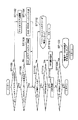
図14は、図1の装置による全体的な録画処理手順を説明するフローチャート図である。以下、通常の静止画録画時の処理を、図14のフローに従って説明する。
【0115】
まず、ディスク100からファイルシステムのデータが読み込まれ(ステップST100)、そのディスクの空き容量がチェックされる(ステップST102)。空き容量がないときは(ステップST102ノー)表示部608および/またはTV637に「録画スペースがありません」といった警告表示を出力し、録画処理を終了する。
【0116】
ディスク100に空き容量があるときは(ステップST102イエス)、録画前処理が行われる(ステップST110)。この前処理において、管理領域の書き込み(VMGファイルの取り込みと作成)その他が行われる。
【0117】
次に、キー入力部607などからユーザにより静止画を取り込むスチルモードが設定されているかどうかチェックされる(ステップST112)。スチルモードが設定されていなければ(ステップST112ノー)、ムービーモードによる動画ビデオ録画などの処理にリターンする。
【0118】
スチルモードが設定されていれば(ステップST112イエス)、ユーザに、音声記録の有無を設定させ、さらに記録時間を設定させる(ステップST114)。音声記録なしの場合は、ユーザにスチル時間を設定させる(ステップST114)。さらにSTC部650をリセットし、各エンコード部616〜618の初期設定を行う(ステップST114)。
【0119】
ここで、VMGがディスク100に記録されている場合には、そのストリーム情報STIより希望の属性に合うSTIが選択され、選択されたSTIの値が各エンコード部616〜618にセットされる(ステップST114)。
【0120】
VMGがディスク100に記録されていない場合には、図1の装置(MPU部604)がVMGを発生してSTIテーブルに登録しても良い。この処理は、静止画記録再生の場合だけでなく、動画処理の場合にも行われる。ただし、図14のフローでは、録画終了時にこのVMG登録(書き込み)処理を行っている。
【0121】
次に、図1のキー入力部607または図示しないリモートコントローラに設けられた録画キー/RECキー(機能上カメラのシャッターボタンに相当の)が入力されたかどうかがチェックされる(ステップST116)。
【0122】
録画キー/RECキーの入力があった場合(ステップST116イエス)は、録画開始設定がなされる(ステップST118)。この設定において、1ピクチャ(静止画1枚)分の録画命令がビデオエンコード部616に設定され、音声記録ありの場合はその録音時間と録音開始命令がオーディオエンコード部617に設定される(ステップST118)。
【0123】
こうして1ピクチャ分の静止画ビデオ信号がエンコーダ部601に取り込まれ、取り込まれた静止画が圧縮されパック化されて、ディスク100に記録される。このとき、音声記録が指定されている場合には、エンコーダ部601に取り込まれた音声も圧縮されパック化されてディスク100に記録される。こうしてパック化された静止画および音声の記録アドレスは、ファイルシステムを参照して決定される(ステップST120)。
【0124】
このステップST120において、書き込みアドレスの他に書き込みサイズも決定され、決定されたアドレスおよびサイズに基づいて、MPU部604がディスクドライブ部609に書き込み命令を発行する。この命令発行とともに、MPU部604はVOG情報(図7(d)のS_VOGI)を作成する(ステップST120)。この作成されたVOG情報により、指定された枚数(図12のS_VOB_Ns)の静止画のグループ化などが行われる。
【0125】
なお、前記録画キー/RECキーの入力がない場合(ステップST116ノー)には、ステップST118およびステップST120の処理はスキップされる。
【0126】
次に、図1のキー入力部607または図示しないリモートコントローラに設けられた録画処理終了キー/STOPキーが押されたかどうかがチェックされる(ステップST122)。
【0127】
録画処理終了キー/STOPキーの入力がなければ(ステップST122ノー)、ディスク100に録画可能な残り容量があるかどうかのチェックが行われる(ステップST132)。
【0128】
ディスク100に残り容量があれば(ステップST132ノー)、ステップST116に戻って、ステップST118〜ST120の処理が反復される。
【0129】
ディスク100に残り容量がなければ(ステップST132イエス)、表示部608および/またはTV637に「録画スペースがありません」といった警告表示を出力し(ステップST134)、録画終了処理(ステップST140)に移行する。
【0130】
なお、前記録画処理終了キー/STOPキーの入力があった場合(ステップST122イエス)には、ステップST132およびステップST134の処理はスキップされて、録画終了処理(ステップST140)に移行する。
【0131】
ステップST140の録画終了処理では、VMGファイルを終了させ、VMGファイル、ビデオファイルをファイルシステムに登録し更新する。
【0132】
具体的には、この録画終了処理において、切り分け情報などからS_AVFIT(VOG情報S_VOGIを含む)およびPGCIを完成させ、録画に使用したストリーム情報STIがビデオマネージャ情報VMGIにあるかどうかを調べる。このSTIがVMGIにない場合は、録画に使用したSTIをVMGIに登録する。このSTIがVMGIにある場合は、録画に使用したSTI番号をS_VOGIに登録する。そして図1のフォーマッタ部619を初期化し、しかる後に、VMGへ、PGCI、切り分け情報などの書き込みが行われる(ステップST140)。
【0133】
図15は、図14の処理手順における録画前処理(ステップST110)の内容を説明するフローチャート図である。以下、録画開始時の前処理について、図15のフローに従って説明する。
【0134】
まず、ディスク100のボリュームストラクチャからファイルシステムをチェックする(ステップST1100)。ディスク100にボリュームストラクチャが記録されていない場合は(ステップST1100ノー)、ファイルシステムが構築され(ステップST1102)、図2に示すようなDVD−RTRディレクトリが作成される(ステップST1104)。
【0135】
ディスク100にボリュームストラクチャが記録されている場合は(ステップST1100イエス)、DVD−RTRディレクトリがチェックされる(ステップST1106)。DVD−RTRディレクトリがない場合は(ステップST1106ノー)、DVD−RTRディレクトリが作成される(ステップST1108)。
【0136】
DVD−RTRディレクトリがある場合(ステップST1106イエス)、あるいはDVD−RTRディレクトリが作成された場合(ステップST1104またはST1108)は、ディスク100から読み出したファイルシステムにエラーが発生したかどうかのチェックが行われる(ステップST1110)。
【0137】
エラーが発生した場合は(ステップST1110イエス)、図1の表示部608および/またはTV637で「ファイルシステムでエラーが発生しました」等の表示を行い(ステップST1112)、処理を終了するか、エラー修復(またはシステムのリスタート)処理などへリターンする。
【0138】
エラーが発生しなければ(ステップST1110ノー)、管理情報VMGがディスク100にあるかどうかチェックされる(ステップST1114)。
【0139】
VMGがなければ(ステップST1114ノー)、VMGが作成される(ステップST1116)。このとき作成されたVMGは、ディスク100の管理ファイル(VR_MANGR.IFO)に記録してもよいが、図1のメインMPU部604のワークRAM604aに展開するだけとし、ディスク100に記録しなくてもよい。その場合、録画終了時に、録画内容を反映させた形で更新された内容のVMGをディスク100の管理ファイル(VR_MANGR.IFO)に保存すればよい。
【0140】
VMGがディスク100にあれば(ステップST1114イエス)、そのVMGがディスク100からメインMPU部604のワークRAM604aに読み込まれる(ステップST1118)。
【0141】
ここでエラーが発生しなければ(ステップST1120ノー)、図14のステップST112にリターンする。エラーが発生すれば(ステップST1120イエス)、表示部608および/またはTV637で「管理データの作成ができませんでした」等の表示を行い(ステップST1122)、処理を終了するか、エラー修復(またはシステムのリスタート)処理などへリターンする。
【0142】
図15の録画前処理を行うタイミングは、次の3種類のタイミングが考えられる。
【0143】
第一は、ディスク100を図1のディスクドライブ部609に装填したとき直ちに行う方法である。この方法では、録画キー/RECキーを押した後、録画をすぐに開始できるという利点があるが、ディスク100を装填したときに準備時間が若干多くかかることになる。
【0144】
第二は、キー入力部607の図示しないフォーマットボタンを押した時に行う方法である。この方法には、記録前には必ずフォーマットキーを押さなければならないという欠点がある。
【0145】
第三は、録画開始時に行うという方法である。この方法だと、録画キー/RECキーを押した後、録画開始まで若干のタイムラグが生じるため、その間の記録データを一時記憶部611に保存することが必要となってくる。
【0146】
図16は、図14の処理手順におけるVOG情報作成処理(ステップST120)の内容を説明するフローチャート図である。
【0147】
まず、記録した静止画VOBのパック数、オーディオのパック数、オーディオの再生時間、副映像SPの有り/無しなどを切り分け情報として取り込み、図8〜図11のVOB_ENTに登録する(ステップST1200)。
【0148】
次に、複数静止画のVOG化の条件がチェックされる(ステップST1202)。このVOG化条件としては、以下のもの(単独あるいは2以上の組合せ)がある:
条件1:静止画の記録枚数が一定数(たとえば64枚)に達したかどうか;
条件2:記録の日付(時間)が設定されている場合において、その日付(時間)が変わったか(あるいは規定の時間に達したか)どうか;
条件3:ユーザが手動で図示しないVOGの切り替えキー(グループ化キー)を押したかどうか;
条件4:静止画記録モードが変更されたか(静止画のソース属性が変わったか)どうか;
など。
【0149】
上記条件1〜4のいずれか1以上に該当すれば(ステップST1202の条件該当)、そのVOGを閉じ、図12のS_VOG_GIに、各種情報(該当S_VOGに登録した静止画VOBの数、VOGの属性情報と一致するストリーム情報STIの番号、最初のVOBの記録開始時間、最後のVOBの記録開始時間など)を登録する(ステップST1204)。
【0150】
上記条件1〜4のいずれにも該当しなければ(ステップST1202の非該当)、ステップST1204の処理はスキップされる。
【0151】
図17は、図14の処理手順における録画後処理(ステップST140)の内容を説明するフローチャート図である。この処理は、動画/静止画に共通して行われる。
【0152】
まず、メインMPU部604は、フォーマッタ部619より受け取った切り分け情報を元に、ワークRAM604a内のVMGを更新する(ステップST1400)。
【0153】
次に、録画に使用した属性データがVMG内のストリーム情報STIのテーブルにあるかどうかをチェックする(ステップST1402)。属性データがSTIテーブルに存在する場合には(ステップST1402イエス)、そのSTI番号をM_VOBI(動画の場合)またはS_VOGI(静止画の場合)に登録する(ステップST1404)。
【0154】
属性データがSTIテーブルに存在しない場合は(ステップST1402ノー)、記録されているSTIの数が最大値に達しているか(つまりSTIテーブルに空きがあるかどうか)がチェックされる(ステップST1406)。STIの数が最大値に達していない(つまりSTIテーブルに空きがある)場合は(ステップST1406ノー)、録画に使用したSTI情報をSTIテーブルに登録し、さらに、M_VOBI(動画の場合)またはS_VOGI(静止画の場合)に、その新しく登録したSTIの番号を登録する(ステップST1408)。
【0155】
STIの数が最大値に達している(つまりSTIテーブルに空きがない)場合は(ステップST1406イエス)、登録されているM_VOBI(動画の場合)またはS_VOGI(静止画の場合)を調べ、使用していないSTIがあるかどうかチェックする(ステップST1410)。未使用のSTIがある場合には(ステップST1410イエス)、未使用STI情報の登録を消して新たなSTIを確保し、その確保したSTIの所に録画に使用したSTI情報を登録して(ステップST1412)、ステップST1408に移行する。ステップST1408では、ステップST1412で登録したSTIの番号が登録される。
【0156】
未使用のSTIが無い場合には(ステップST1410ノー)、図1の表示部608および/またはTV637でエラー表示を行って(ステップST1414)図17の処理をエラー終了する。
【0157】
M_VOBI(動画の場合)またはS_VOGI(静止画の場合)にSTI番号が登録されたら(ステップST1404またはST1408)、ファイルシステム内のDVD_RTAVディレクトリ(図2)下のディレクトリレコード情報にVROファイル(VOBSファイル)が存在するかどうかがチェックされる(ステップST1416)。
【0158】
VROファイル(VOBSファイル)が存在する場合は(ステップST1416イエス)、そのVROファイル(VOBSファイル)の情報を(記録したビデオファイルの情報に)更新することで、ディレクトリレコードを更新する(ステップST1418)。VROファイル(VOBSファイル)が存在しない場合は(ステップST1416ノー)、VROファイル(VOBSファイル)のディレクトリレコード情報を(記録したビデオファイルの情報に)追加登録する(ステップST1420)。
【0159】
ディレクトリレコード情報の更新(ステップST1418)あるいは登録(ステップST1420)が済むと、DVD_RTAVディレクトリ(図2)下のディレクトリレコード情報内にVR_MANGR.IFOファイル(VMGファイル)があるかどうかがチェックされる(ステップST1422)。
【0160】
VR_MANGR.IFOファイル(VMGファイル)がある場合(ステップST1422イエス)には、このIFOファイルの位置にワークRAM604a内のVMG情報を書き込んで、DVD_RTAVディレクトリ下のディレクトリレコード情報を更新する(ステップST1424)。
【0161】
VR_MANGR.IFOファイル(VMGファイル)がない場合(ステップST1422ノー)は、ワークRAM604a内に構築したVMGの情報をディスク100の空き領域に記録し、DVD_RTAVディレクトリ下のディレクトリレコード情報にIFOファイルの情報を追加登録する(ステップST1426)。
【0162】
なお、図17のストリーム情報STIに関する処理は、録画前に行うこともできる。
【0163】
図18〜図20は、図1の装置による静止画連続取り込み録画の処理手順を説明するフローチャート図である。
【0164】
まず、ディスク100からファイルシステムのデータが読み込まれ(ステップST200)、そのディスクの空き容量がチェックされる(ステップST202)。空き容量がないときは(ステップST202ノー)表示部608および/またはTV637に「録画スペースがありません」といった警告表示を出力し、録画処理を終了する。
【0165】
ディスク100に空き容量があるときは(ステップST202イエス)、録画前処理が行われる(ステップST110)。この前処理において、VMGファイルが取り込まれ、その各設定値(PGCI、S_VOGI等)がメインMPU部604のワークRAM部604aに保存される。
【0166】
次に、キー入力部607などからユーザにより複数の静止画を連続して取り込むスライドショー取り込みモードが設定されているかどうかチェックされる(ステップST212)。スライドショー取り込みモードが設定されていなければ(ステップST212ノー)、他の処理にリターンする。
【0167】
スライドショー取り込みモードが設定されていれば(ステップST212イエス)、ユーザに、音声記録の有無を設定させ、さらに音声記録時間を(時間無制限も含めて)設定させる(ステップST214)。音声記録しない場合は、ユーザにスチル時間を設定させる(ステップST214)。設定された最大録音時間(あるいは時間無制限状態)もしくはスチル時間は、ワークRAM部604aに保存される。さらにSTC部650をリセットし、各エンコード部616〜618の初期設定を行う(ステップST214)。
【0168】
この初期設定において、静止画記録モード(Iピクチャスチル記録モード)、VOG切り分けモード、音声記録時間等が設定される。また、ワークRAM部604a内のストリーム情報STIデータが調査され、録画すべきデータの属性情報と一致しているものがあれば、そのSTI番号がワークRAM部604aに保存される。録画すべきデータの属性情報と一致しているものがない場合は、この録画すべきデータの属性情報がSTIとしてワークRAM部604aに保存される。
【0169】
また、ステップST214の初期設定において、ユーザに、スライドショー撮影時の録画日時を設定させ、それをワークRAM部604aに保存するとともにフォーマッタ部619に設定する(ステップST214)。なお、録画日時のユーザ設定がなされない場合は、その取り込んだ日時が設定される。
【0170】
さらに、ステップST214の初期設定において、ユーザに、映像変化後の取り込み開始フレーム数を指定させる(ステップST214)。この取り込み開始フレーム数は、映像が変化した後何フレーム目の映像を取り込むかを指定するものであるが、指定しない場合は、変化後すぐの映像フレームを取り込むことになる。(ただし、変化後、一定のフレーム数が連続したことを検知して取り込む方法を採用している場合は、このフレーム数をユーザに指定させる必要はない。)ここで、映像変化後何番目のフレームを取り込むのかを指すフレーム数をユーザに指定させるのは、電子スチルカメラなどでスライドショー再生を行っている場合に、フェードイン、フェードアウトなどのエフェクト処理を行っている場合に対応するため(フェードイン中あるいはフェードアウト中のフレームを取り込まないようにするため)である。
【0171】
このようなフレーム数指定の代わりに、フレーム変化検知後、同じ映像フレームが一定数連続したことを検知し、その検知した信号をトリガとしてフレームデータを取り込むことも考えられる。
【0172】
続いて、図1のキー入力部607または図示しないリモートコントローラに設けられたスライドショー取り込み開始キー(図示せず)の入力チェックがなされる(ステップST216)。
【0173】
開始キー入力があった場合(ステップST216イエス)は、エンコーダ部601に対して録画開始設定がなされる(ステップST218)。この設定において、1フレーム(または1フィールド)分をIピクチャとしてエンコードする設定と、オーディオエンコードが設定されている場合にはオーディオエンコード部617にオーディオエンコードの開始および最大録音時間または時間無制限を指定する設定とがなされる。
【0174】
ステップST218で録画開始設定がなされたあと、録画終了キーの入力チェック(ステップST222)、録音時間の経過チェック(ステップST224)、および映像内容の変化チェック(ステップST226)がなされる。
【0175】
録画終了キーの入力がなく(ステップST222ノー)、設定された最大録音時間まで経過しておらず(ステップST224ノー)、映像内容に変化も起きていない(ステップST226ノー)ときは、それまでのエンコードデータ量(フォーマッタ部619で圧縮されパック化されたデータ量)がバッファメモリ部620に一定量貯まったかどうかチェックされる(ステップST228)。バッファメモリ部620に貯まったエンコードデータ量が一定量に達していないときは(ステップST228ノー)、それが一定量に達するまでステップST222〜ST228の処理ループが反復される。
【0176】
バッファメモリ部620に貯まったエンコードデータ量が一定量に達すると(ステップST228イエス)、その一定量のデータ(パック)の書き込みアドレスおよびデータサイズがファイルシステムにより決定され、それがディスクドライブ部609によりディスク100に書き込まれる(ステップST230)。
【0177】
この書き込み時に、ディスク100に録画可能な残り容量があるかどうかのチェックが行われる(ステップST232)。ディスク100に残り容量があれば(ステップST232ノー)、ステップST222に戻って、ステップST222〜ST230の処理が反復される。
【0178】
ディスク100に残り容量がなければ(ステップST232イエス)、表示部608および/またはTV637に「残り容量がありません」あるいは「録画スペースがありません」といった警告表示を出力し(ステップST234)、図20の録画終了処理(ステップST140)に移行する。なお、ステップST222において録画終了キーの入力があった場合も(ステップST222イエス)、図20の録画終了処理(ステップST140)に移行する。
【0179】
ステップST224において設定された最大録音時間まで経過したとき(ステップST224イエス)、あるいはステップST226において映像内容に変化が生じたときは(ステップST226イエス)、図19のステップST220へ移行する。
【0180】
ステップST220では、オーディオエンコード部617にエンコード終了命令が発行される。すると、今までエンコードされたデータがバッファメモリ部620から読み出されてディスク100に書き込まれる(その書き込みアドレスおよびデータサイズすなわち未記録の残りデータ量はファイルシステムにより決定される)。そして、VOBU(図3)のパック数などが、切り分け情報(VOBI情報)として、ワークRAM部604aに保存される。さらに、1グループ内の静止画枚数上限到達、静止画の属性変化などにより新たなグループ化が必要となった場合は、VOG分けが行われ、そのVOG情報(S_VOGI)が作成されて、ワークRAM部604aに保存される。
【0181】
その後、映像内容の変化が起きる(ステップST236イエス)まで待ち、映像内容に変化が起きた後さらに指定されたフレーム数が経過する(ステップST238イエス)まで待つ。そうしてから、図18のステップST218に戻って、ステップST222〜ST232の処理ループにより、取り込んだスライドショーの静止画群をディスク100に書き込むことになる。
【0182】
なお、ステップST236において映像内容変化を検知した後、ステップST238において同じ内容の映像フレームが所定数連続したかどうかをチェックし、同じ内容の映像フレームが所定数連続したら(ステップST238イエス)、図18のステップST218に戻るように構成することもできる。
【0183】
図18の処理において、録画終了キー入力があった場合(ステップST222イエス)あるいは「残り容量がありません」といった警告表示が出力(ステップST234)されたあと、図20の録画終了処理(ステップST140)が実行されてから、図18〜図20の処理は終了する。
【0184】
この録画終了処理(ステップST140;図14のST140に相当)において、
*切り分け情報(S_VOGI等)が構成され、
*録画に使用したストリーム情報STIがVMGにあるかどうか調査され、ない場合は録画に使用したSTIが登録され、ある場合は該当STI番号がS_VOGIに登録され、
*フォーマッタ部619の初期化が行われ、
*録画情報(PGCI設定、切り分け情報など)のVMGファイルへの書き込み(VMGの更新)が行われる。
【0185】
以上述べた図18〜図20の処理により、ユーザに面倒な操作負担をかけずに、静止画の連続取り込みを容易に実現できる。
【0186】
図21は、図1の装置による全体的な再生処理手順を説明するフローチャート図である。
【0187】
まず、図1のディスクドライブ部609に装填されたディスク100がチェックされる(ステップST300)。ディスク100が不良である場合あるいは図1のシステムで対応できない規格のディスクである場合は(ステップST300のNG)、エラー処理が行われ(ステップST302)、図21の処理は終了する。
【0188】
ディスク100が正常である場合は(ステップST300のOK)、そのディスクにボリュームストラクチャが記録されているかどうかチェックされる(ステップST304)。ボリュームストラクチャが記録されている場合は(ステップST304イエス)、DVD_RTRディレクトリ(図2)の存在がチェックされる(ステップST306)。
【0189】
DVD_RTRディレクトリがない場合(ステップST306ノー)あるいはボリュームストラクチャが記録されていなかった場合(ステップST304ノー)は、「録画されていません」などのメッセージ表示がなされてから(ステップST308)、図21の処理は終了する。
【0190】
DVD_RTRディレクトリがある場合は(ステップST306イエス)、エラー発生の有無がチェックされる(ステップST310)。エラーが発生したときは(ステップST310イエス)、「ファイルシステムでエラーが発生しました」などのメッセージ表示がなされてから(ステップST312)、図21の処理は終了する。
【0191】
エラーがないときは(ステップST310ノー)、ディスク100にVMGファイルがあるかどうかチェックされる(ステップST314)。VMGファイルがあるときは(ステップST314イエス)そのVMGファイルの内容が読み込まれ(ステップST318)、そこに図2に示すようなVR_MOVIE.VRO、VR_STILL.VRO、VR_AUDIO.VROなどのVROファイルがあるかどうかチェックされる(ステップST320)。
【0192】
VROファイルがない場合(ステップST320ノー)あるいはVMGファイルがなかった場合(ステップST314ノー)は、「録画されていません」などのメッセージ表示がなされてから(ステップST316)、図21の処理は終了する。
【0193】
VROファイルがある場合は(ステップST320イエス)、再生開始するプログラム番号およびセル番号がユーザなどにより選択されて決定される(ステップST322)。
【0194】
再生開始するプログラム番号およびセル番号が決定されると、図1のビデオデコード部628、SPデコード部627、オーディオデコード部630それぞれの初期設定が行われる(ステップST324)。この初期設定において、ビデオデコード部628は、静止画再生モード(スチルピクチャモード)に設定され、STC部650を無視してMPEGビデオのIピクチャ再生を行なうようになる。
【0195】
その後に静止画などのセル再生処理に入る(ステップST330)。このセル再生処理の詳細は、図22および図23を参照して後述する。
【0196】
セル再生が継続している間は(ステップST332ノー)、PGCIより次の再生セルが設定されて(ステップST334)、ステップST330のセル再生処理が反復実行される。
【0197】
セル再生が終了すると(ステップST332イエス)、エラーの発生がチェックされる(ステップST336)。エラーがなければ(ステップST336ノー)その他の再生終了時の処理が行われてから(ステップST338)、図21の処理は終了する。エラーがあった場合は(ステップST336イエス)、「読み出しエラーが発生しました」などのメッセージ表示がなされてから(ステップST340)、再生終了処理が実行されて(ステップST342)、その他の処理ルーチンにリターンする。
【0198】
図22および図23は、図21の処理手順におけるセル再生時の処理(ステップST330)の具体的な処理内容を説明するフローチャート図である。
【0199】
図22において、図4のPGCIおよび図7のS_AVFITの内容から、再生しようとするセルの開始位置(FP)が決定される(ステップST3300)。この位置(FP)は、論理ブロック番号(LBN)で表される。
【0200】
このステップST3300の処理において、再生を開始するビデオオブジェクトVOBの番号がパラメータ“n”に設定され、再生するビデオオブジェクトグループVOGのストリーム情報STIがワークRAM部604aに読み込まれ、それらが各デコード部627〜630に設定される。
【0201】
次に再生しようとするVOBに一時消去状態を示すテンポラリイレーズフラグがついており、そのフラグがオンになっているかどうかがチェックされる(ステップST3302)。このテンポラリイレーズフラグオンの状態は、たとえば該当VOBのファイルがごみ箱アイコンに捨てられた状態に対応する。
【0202】
テンポラリイレーズフラグオンのVOBはまだ実際に消去された訳ではないが、再生対象からは外される。現在のVOBのテンポラリイレーズフラグがオンであれば(ステップST3302イエス)、後述する図23のステップST3336に処理がジャンプする。
【0203】
現在のVOBのテンポラリイレーズフラグがオフであれば(ステップST3302ノー)、PGCIおよびS_AVFITの内容(再生するVOB番号nとビデオ/オーディオの属性情報を含むストリーム情報STI)から、再生しようとするn番目のVOBの開始位置(FP)が決定される(ステップST3304)。
【0204】
次に、決定されたn番目のVOBのエントリタイプVOB_ENTが、図8〜図11のタイプA〜タイプDのどれであるかの判定が行われる(ステップST3310)。
【0205】
VOB_ENTがタイプAであれば、図示しないスチルタイム(静止画表示時間)の情報(STILL_TM)が図4(a)のRTR_VMGIから読み出されて設定され(ステップST3312)、ディスクドライブ部609にデータ読み出し命令がセットされる(ステップST3324)。
【0206】
VOB_ENTがタイプBであれば、スチルタイムが0xFFFF(オーディオ再生時間)に設定され、静止画に重畳されたオーディオが再生されるように設定される(ステップST3314)。そして、オーディオ開始の再生タイムスタンプPTSがSTC部650に設定されてから(ステップST3322)、ディスクドライブ部609にデータ読み出し命令がセットされる(ステップST3324)。
【0207】
VOB_ENTがタイプCのときは、スチルタイムが0xFFFF(オーディオ再生時間)に設定され、アディショナルオーディオ(付加オーディオAA)が再生されるように設定される(ステップST3316)。その際、該当VOBの転送終了アドレスがビデオパートのみとなるように設定される。その後、ステップST3322に処理が移行する。
【0208】
VOB_ENTがタイプDのときは、まずアディショナルオーディオが選択されているかどうかがチェックされる(ステップST3318)。アディショナルオーディオが選択されているなら(ステップST3318イエス)、ステップST3316に処理が移行する。アディショナルオーディオが選択されていないなら(ステップST3318ノー)、スチルタイムが0xFFFF(オーディオ再生時間)に設定され、静止画に重畳されたオーディオが再生されるように設定される(ステップST3320)。その後、ステップST3322に処理が移行する。
【0209】
図22においてディスクドライブ部609にデータ読み出し命令がセットされると(ステップST3324)、処理は図23のステップST3326に移行する。ステップST3326では、ディスクドライブ部609へのデータ転送が開始されたかどうかチェックされる。
【0210】
データ転送が開始されると(ステップST3326イエス)、アディショナルオーディオのデータも転送するかどうかのチェックが行われる(ステップST3328)。
【0211】
アディショナルオーディオのデータを転送する場合は(ステップST3328イエス)、PGCIおよびS_AVFITの内容から、再生しようとするn番目のVOB_ENTに付いているアディショナルオーディオ開始位置(FP)および終了位置(FP)が決定される(ステップST3330)。
【0212】
その後、開始位置(FP)および終了位置(FP)がファイルシステムにより物理アドレスに変換され、その物理アドレスデータに基づいて、ディスクドライブ部609にデータ読み出しの命令がセットされる(ステップST3332)。
【0213】
こうしてディスクドライブ部609により読み出されたデータの転送が終了すると(ステップST3334イエス)、キー入力部607あるいは図示しないリモートコントローラから何らかのユーザキー入力があったかどうかチェックされる(ステップST3336)。
【0214】
ユーザからストップキー入力があった場合は(ステップST3336イエス、ST3338イエス)、再生ストップの処理へリターンする。ユーザから何らキー入力がなく(ステップST3336ノー)、再生時間も終了していなければ(ステップST3342ノー)、ステップST3336およびST3342の処理ループが反復される。なお、ステップST3342における判定は、オーディオ再生時にはその再生時間が終了したかどうかで行われ、その他の再生時にはスチル時間(静止画再生時間)が終了したかどうかで行われる。
【0215】
一方、ユーザからストップキー入力でなくプレイキー入力があった場合(ステップST3336イエス、ST3338ノー、ST3340イエス)、あるいはステップST3342で再生時間が終了したときは(ステップST3342イエス)、図22のステップST3300で設定されたパラメータ“n”がインクリメントされる(ステップST3344)。
【0216】
こうしてインクリメントされた“n”がセル内の総ピクチャ数以内であれば(ステップST3346ノー)、図22のステップST3302に戻って、ST3302〜ST3346の処理が反復される。
【0217】
一方、インクリメントされた“n”がセル内の総ピクチャ数を超えると(ステップST3346イエス)、図22および図23の再生処理は終了し、その他の処理へリターンする。
【0218】
【発明の効果】
以上説明したように、この発明によれば、ユーザが1枚1枚の取り込み静止画を逐一選択・設定しなくても、ビデオ信号から複数静止画を簡単に連続取り込みできる静止画連続取込機能付きデジタル映像情報装置を得ることができる。
【0219】
また、ユーザが1枚1枚の取り込み静止画を逐一選択・設定しなくても、ビデオ信号から複数静止画を簡単に連続記録できる複数静止画記録方法を得ることができる。
【図面の簡単な説明】
【図1】この発明の一実施の形態に係る静止画連続取込機能付きデジタル映像情報装置(RTR−DVDビデオレコーダ)の全体構成を説明するブロック図。
【図2】図1の情報媒体(DVD−RAM、DVD−RW、DVD−R、HDD等)に記録されるデジタル情報ファイルのディレクトリ構造を説明する図。
【図3】図1の情報媒体(DVD−RAM、DVD−RW、DVD−R、HDD等)に記録されるデジタル情報に含まれるビデオオブジェクトセット(VOBS)のデータ構造を説明する図。
【図4】図1の情報媒体(DVD−RAM、DVD−RW、DVD−R、HDD等)で用いられる管理情報(VMG/PGCI/CI)のデータ構造を説明する図。
【図5】図4の管理情報(CI)に含まれるセル一般情報C_GIの内容を説明する図。
【図6】図4の管理情報(CI)に含まれるセルエントリポイント情報C_EPIの内容を説明する図。
【図7】図1の情報媒体(DVD−RAM、DVD−RW、DVD−R、HDD等)で用いられる静止画の管理情報(VMG/S_AVFIT/S_AVFI/S_VOGI)のデータ構造を説明する図。
【図8】図7の静止画管理情報(S_VOGI)に含まれる静止画ビデオオブジェクトエントリS_VOB_ENT(タイプA)の内容を説明する図。
【図9】図7の静止画管理情報(S_VOGI)に含まれる静止画ビデオオブジェクトエントリS_VOB_ENT(タイプB)の内容を説明する図。
【図10】図7の静止画管理情報(S_VOGI)に含まれる静止画ビデオオブジェクトエントリS_VOB_ENT(タイプC)の内容を説明する図。
【図11】図7の静止画管理情報(S_VOGI)に含まれる静止画ビデオオブジェクトエントリS_VOB_ENT(タイプD)の内容を説明する図。
【図12】図7の静止画管理情報(S_VOGI)に含まれる静止画ビデオオブジェクトグループ一般情報S_VOG_GIの内容を説明する図。
【図13】図7の静止画管理情報(S_AVFIT)に含まれる静止画ビデオオブジェクトストリーム情報S_VOB_STIの内容を説明する図。
【図14】図1の装置による全体的な録画処理手順を説明するフローチャート図。
【図15】図14の処理手順における録画前処理の内容を説明するフローチャート図。
【図16】図14の処理手順におけるVOG情報作成処理の内容を説明するフローチャート図。
【図17】図14の処理手順における録画後処理の内容を説明するフローチャート図。
【図18】図1の装置による静止画連続取り込み録画の処理手順(その1)を説明するフローチャート図。
【図19】図1の装置による静止画連続取り込み録画の処理手順(その2)を説明するフローチャート図。
【図20】図1の装置による静止画連続取り込み録画の処理手順(その3)を説明するフローチャート図。
【図21】図1の装置による全体的な再生処理手順を説明するフローチャート図。
【図22】図21の処理手順におけるセル再生時の処理手順(その1)を説明するフローチャート図。
【図23】図21の処理手順におけるセル再生時の処理手順(その2)を説明するフローチャート図。
【符号の説明】
100…光ディスク/情報記憶媒体(DVD−RAM、DVD−RW、DVD−Rその他の録再可能情報媒体);
601…エンコーダ部;
602…デコーダ部;
604…メインMPU部;
604a…ワークRAM部;
604b…漢字ROM(キャラクタROM)部;
604c…プログラムROM部;
6041…ディレクトリ検知部;
6043…ビデオオブジェクトグループ化(VOG化)部;
605…ビデオミキシング部;
606…フレームメモリ部;
607…キー入力部;
608…表示部;
609…ディスクドライブ部;
610…データプロセサ(D−PRO)部;
611…一時記憶(バッファ)部;
612…A/V入力部;
613…TVチューナ部;
614…A/D変換部;
616…ビデオエンコード部;
617…オーディオエンコード部;
618…副映像(サブピクチャSP)エンコード部;
619…フォーマッタ部;
620…バッファメモリ部;
625…分離部;
626…メモリ;
627…副映像(SP)デコード部;
628…ビデオデコード部;
628a…縮小画像(サムネールピクチャ)生成部;
630…オーディオデコード部;
631…デジタル出力I/F(オーディオ用);
632…D/A変換部(オーディオ用);
633…外部スピーカ;
634…デジタル出力I/F(ビデオ用);
636…D/A変換部(ビデオ用);
637…外部モニタTV;
638…ビデオプロセサ(V−PRO)部;
650…システムタイムクロック(STC)部;
700…ハードディスクドライブ(HDD)レコーダユニット。[0001]
BACKGROUND OF THE INVENTION
The present invention relates to a digital video information apparatus having a still image continuous capturing function.
[0002]
[Prior art]
Currently, MPEG2 (Moving Picture Expert Group 2) system is used for digital recording / playback of video (moving picture), and AC-3 (Digital Audio Compression 3) system is used for digital recording / playback of audio (voice). The DVD video standard is compiled, and various playback devices (DVD video players) using this standard are commercially available.
[0003]
This DVD video standard supports MPEG-2 as a moving picture compression system and AC-3 audio and MPEG audio as an audio recording system in addition to linear PCM according to the MPEG2 system layer. This DVD video standard also supports sub-picture data for subtitles, navigation data for playback control such as fast-forward / rewind data search, and ISO 9660 and UDF bridge formats for computers.
[0004]
Furthermore, writable DVD discs (read-write DVD-RAM, rewritable DVD-RW, or write-once DVD-R) have been developed, and digital video information using writable DVD discs An environment that enables development of recording / playback devices (digital video disk recorders replacing conventional analog video cassette recorders) has been created.
[0005]
From the above situation, a real-time recording standard for DVDs (RTR-DVD standard) has been proposed to perform digital recording / playback of video images and the like in real time, and is being put together as an official standard. This RTR-DVD standard is considered based on the DVD video standard that has already been accepted by the market as an official standard, and a file system corresponding to this RTR-DVD standard is currently being standardized.
[0006]
[Problems to be solved by the invention]
By the way, according to the RTR-DVD standard, a maximum of 63936 still images (still pictures) (= maximum number of still cells 999 × maximum number 64 in a video object group) can be recorded. As a still image source, an electronic still camera (digital camera) can be considered. In this electronic still camera, a semiconductor memory such as an IC card is used as a recording medium for captured still images.
[0007]
On the other hand, a disc medium such as an optical disc is used for the RTR-DVD video recorder. That is, the recording medium used differs between the electronic still camera and the RTR-DVD video recorder. For this reason, it is not easy to directly capture still image data created by an electronic still camera into an RTR-DVD video recorder.
[0008]
In addition, when capturing a plurality of still images from a video signal (a normal video signal or a video signal including a plurality of still images created by an electronic still camera or a digital video movie) Each captured still image must be selected and set, which is very troublesome.
[0009]
The present invention has been made in view of the above circumstances, and it is possible to continuously capture a plurality of still images from a video signal without the user having to select and set each captured still image one by one. An object of the present invention is to provide a digital video information apparatus with a built-in function.
[0010]
Another object of the present invention is to provide a multiple still image recording method for continuously capturing and recording a plurality of still images from a video signal without the user having to select and set each captured still image one by one. That is.
[0011]
[Means for Solving the Problems]
In order to achieve the above object, a digital video information apparatus according to the present invention includes a key input unit (607) for designating a still image continuous capture mode; and a video signal input after shifting to the still image continuous capture mode. A frame change detection unit (604) for detecting that the captured frame is different in video content from the previous frame; based on the information from the detection unit, the captured frame data is compressed into an MPEG I picture, and RTR An encoder unit (601) that generates a pack structure specified by the DVD standard; a reproduction management information generation unit (604) that generates reproduction management information (S_VOG_GI) from information related to an I picture generated by the encoder unit; It is comprised by.
[0012]
In order to achieve the other object, in the multiple still image recording method according to the present invention, a still image group (VOG) of a plurality of still images within a predetermined number (64) is set (ST114 in FIG. 14; ST214 in FIG. 18): After recording of the video information is started (YES in ST116 in FIG. 14; YES in ST216 in FIG. 18), the recording of the plurality of still images included in the video information is performed on the data recording on the information medium (100). Performed continuously on area (recording processing loop including ST118 in FIG. 14; recording processing loop including ST218 in FIG. 18); management for collecting the recorded still images for each still image group (VOG) Information (VOG information; S_VOG_GI in FIG. 13) is created (ST120 in FIG. 14; ST220 in FIG. 19); the information medium on which the plurality of still images are recorded The management information recording area (100) (VMG / S_AVFIT), writes the management information created in the above (S_VOG_GI); and the (ST140 in FIG. 14 ST140 in FIG. 20) as.
[0013]
By doing so, it is possible to construct a system in which a plurality of still images are automatically and continuously captured from a video signal including a plurality of still images that are continuously reproduced as in a slide show and recorded in the RTR-DVD format.
[0014]
DETAILED DESCRIPTION OF THE INVENTION
A digital video information apparatus with a still image continuous capturing function according to an embodiment of the present invention will be described below with reference to the drawings.
[0015]
FIG. 1 is a block diagram illustrating the overall configuration of a digital video information apparatus (RTR-DVD video recorder) with a still image continuous capturing function according to an embodiment of the present invention.
[0016]
The apparatus main body of the RTR-DVD video recorder shown in FIG. 1 is roughly driven to rotate a recordable / reproducible
[0017]
Furthermore, the data bus connecting the
[0018]
The large-capacity high-speed
[0019]
That is, an air check of a TV broadcast program or the like is performed by the
[0020]
Alternatively, for example, an air check of a long-time TV program that does not fit on a 4.7 GB capacity DVD-RAM disk is performed by the
[0021]
Alternatively, a DVD-VR video signal, a DVD-AR audio signal, and a DVD-SR stream signal are arbitrarily mixed and recorded in the
[0022]
The
[0023]
The encoder unit 601 in FIG. 1 includes an A /
[0024]
The A /
[0025]
When an analog video signal and a digital audio signal are input to the A /
[0026]
The digital video signal component from the A /
[0027]
The
[0028]
When a DVD video signal is input from the
[0029]
The
[0030]
Here, a standard encoding process for creating the recording data will be briefly described. That is, when the encoding process is started in the encoder unit 601 in FIG. 1, parameters necessary for encoding video data and other parameters are set. Next, the main video data is pre-encoded using the set parameters, and the optimal code amount distribution for the set average transfer rate (recording rate) is calculated. Based on the code amount distribution obtained by the pre-encoding in this way, the main video is encoded. At this time, audio data is also encoded at the same time.
[0031]
As a result of pre-encoding, when the data compression amount is insufficient (when the desired video program does not fit in the DVD-RAM disc, DVD-RW disc, DVD-R disc, or
[0032]
Similarly, parameters necessary for encoding the sub-picture data are set, and the encoded sub-picture data is created.
[0033]
The main video data, audio data, and sub-video data encoded as described above are combined and converted into an RTR-DVD video structure.
[0034]
The encoded main video data, audio data and sub-video data are subdivided into packs of a certain size (2048 bytes) as shown in the lower part of FIG. A dummy pack (not shown) is appropriately inserted into these packs. Note that time stamps such as PTS (presentation time stamp) and DTS (decode time stamp) are appropriately described in packs other than dummy packs. For the sub-picture PTS, a time arbitrarily delayed from the PTS of the main picture data or audio data in the same reproduction time zone can be described.
[0035]
And each data cell is arrange | positioned per video object unit (VOBU) so that it can reproduce | regenerate in the time code order of each data, and VOB comprised by a some cell is comprised. One or more VR_MOVIE. VRO file, VR_STILL. VRO file, VR_AUDIO. A VRO file or the like is formatted with the directory structure of FIG.
[0036]
If the DVD video playback signal can be digitally copied, the contents of the cell, program chain, management table, time stamp, and the like are determined from the beginning, and need not be created again. However, in order to configure the RTR-DVD video recorder so that the DVD playback signal can be digitally copied, it is necessary to take appropriate copyright protection means.
[0037]
A
[0038]
The D-
[0039]
The
[0040]
For example, when the
[0041]
The temporary storage unit 611 (or HDD recorder unit 700) can be used to temporarily store recording information until the
[0042]
The
[0043]
Although not shown in FIG. 1, if an external card slot is provided in the RTR-DVD video recorder, the EEPROM can be sold separately as an optional IC card. If the RTR-DVD video recorder is provided with an external drive slot or USB interface, the HDD can also be sold separately as an optional expansion drive.
[0044]
When a personal computer with a DVD-RAM drive is converted into an RTR-DVD video recorder by software (not shown), a part of the free area of the hard disk drive of the personal computer itself or a part of the main memory is shown in FIG. 1
[0045]
The
[0046]
The
[0047]
The MPU of the
[0048]
In these processes, data input by the user of the RTR-DVD video recorder (various process commands, still image recording time to be continuously captured, still image continuous capture start command, text input regarding recording contents, etc.) are keys. Provided from the
[0049]
Among the execution results of the
[0050]
The timing at which the
[0051]
The
[0052]
The decoder unit 602 in FIG. 1 includes a
[0053]
Here, the
[0054]
Main video data (including appropriately reduced image data) output from the V-PRO unit 638 and OSD data (such as text) appropriately supplied from the
[0055]
The digital video output from the
[0056]
The digital audio output from the
[0057]
The operation example of the apparatus of FIG. 1 can be summarized as follows. That is, the analog AV signal input from the A /
[0058]
Furthermore, from the
[0059]
At this time, for example, if
Here, as the segmentation information, the size of the VOBU, the playback time from the beginning of the VOBU to the end of the VOBU, the end address of the I picture corresponding to the VOBU, and the like can be considered.
[0060]
Further, it is also conceivable that the
[0061]
The D-
[0062]
Here, when the
[0063]
Here, in the real-time DVD recorder of FIG. 1 using a DVD-RAM or the like, still image processing can be performed, for example, as follows.
[0064]
For example, when a still image video signal is input to the A /
[0065]
Further, when a plurality of still images are taken in, a group is formed with up to 64 still images to form a VOG (video object group). This VOG is an administrative delimiter and corresponds to a VOB in the case of moving image reproduction.
[0066]
For this captured still image, management information (S_AVFI / S_VOGI) is constructed for each VOG, and management information (program chain information) for determining the playback order of the captured multiple still images is registered in ORG_PGCI.
[0067]
At this time, conditions for forming the VOG will be described later with reference to FIG. 16, but when the number of recordings reaches a certain number (usually 64), or when the recording mode of the still image is changed, When a user presses a grouping key (not shown) (a key included in the
[0068]
Actually, the VOG is divided by a combination of the above conditions.
[0069]
Among the above conditions, when the still image recording mode is changed, it means that the resolution of the still image is changed, the audio mono / stereo / dual mono to be played with the still image is switched, and the still image is accompanied. It is conceivable to change the compression method of audio to be played back and to change the palette data of sub-pictures to be played back along with the still image.
[0070]
Information regarding these recording mode changes is recorded in management information S_VOB_STI, which will be described later with reference to FIG. 13. By recording a stream information number (S_VOB_STIN) of the corresponding recording mode in S_VOG_GI in FIG. 12, which will be described later. The information regarding the recording mode change can be processed.
[0071]
FIG. 2 is a diagram for explaining the directory structure of a digital information file recorded on the information medium (DVD-RAM, DVD-RW, DVD-R, HDD, etc.) of FIG.
[0072]
A DVD has a plurality of standards, and a directory exists for each standard. That is, a VIDEO_TS directory (not shown) is provided for DVD video, an
[0073]
In DVD video, data is stored in a normal file format. Each title recorded in the DVD video corresponds to, for example, one movie, and one or more titles are included in one disc. A collection of the titles is called a title set, and the title set is composed of a plurality of files.
[0074]
The title set (VTS) includes a management information file whose information for managing the title set is called video title set information (VTSI), a video file composed of video data, and a backup file of VTSI. ing. Furthermore, in DVD video, a management information file called a video manager (VMG) exists as information for managing this disk in one disk.
[0075]
On the other hand, in the RTR-DVD (recording / playback DVD), as shown in FIG. 2, one video data file VR_MOVIE.
[0076]
In the recording / playback DVD standard, the VMGI and VTSI of the DVD video are combined to form overall management information VMG, and video data files are managed by this VMG.
[0077]
In the RTR-DVD recorder of FIG. 1 according to one embodiment of the present invention, the video file for moving images (VR_MOVIE.VRO231 in FIG. 2) and the data file for still images (VR_STILL.VRO232 in FIG. 2) are stored on one disc. One file each.
[0078]
The video data file is managed in a hierarchical structure as shown in FIG. 2, one video object set (VOBS) is composed of one or more VOBs, and one VOB is one or more video object units. (VOBU). Each VOBU is composed of a plurality of packs composed of various types of data. One pack is composed of a pack header and one or more packets, and each video data and audio data is recorded in this packet.
[0079]
FIG. 3 shows a video object set (video, still image, audio, sub-video, etc.) included in digital information recorded on the information medium (DVD-RAM, DVD-RW, DVD-R, HDD, etc.) shown in FIG. It is a figure explaining the data structure of VOBS. Information contents such as moving image data, still image data, audio data, and sub-video data are recorded in this VOBS.
[0080]
Here, as illustrated in FIG. 3, the still image data is managed as one I picture = 1 VOBU = 1 VOB, and after the video data pack (V pack) column, the sub-picture pack (SP pack). ) Row and audio pack (A pack) row. However, in the case of still image data, sub-picture data and / or audio data are optional and may not be present.
[0081]
Here, a pack is a minimum unit for performing data transfer processing. Further, the minimum unit for performing logical processing is in units of cells, and logical processing is performed in units of cells. The reproduction order of cell data is defined by a program chain (PGC). A plurality of programs (PG) are registered in this PGC, and one or more cells are registered in this PG. It is program chain information (PGCI) included in the VMG that actually records the structure of the PGC. Reproduction processing is performed according to this PGCI, and PGCI is created at the time of recording or editing.
[0082]
FIG. 4 is a diagram for explaining the data structure of management information (VMG / PGCI / CI) used in the information medium (DVD-RAM, DVD-RW, DVD-R, HDD, etc.) of FIG. In RTR-DVD (recording / playback DVD), management information VMG having a structure as shown in FIG. 4 is used.
[0083]
In FIG. 4A, RTR video manager information RTR_VMGI describes basic information of the recordable / reproducible optical disc (RTR disc) 100 of FIG. This RTR_VMGI includes a video manager information management table VMGI_MAT and a playlist search pointer table PL_SRTP.
[0084]
RTR_VMG further includes a movie AV file information table M_AVFIT, a still picture AV file information table S_AVFIT, original PGC information ORG_PGCI, a user-defined PGC information table UD_PGCIT, a text data manager TXTDT_MG, and a manufacturer information table MNFIT.
[0085]
FIG. 4B shows the data structure of UD_PGCIT in FIG. The UD_PGCIT includes user-defined PCG information table information UD_PGCITI, one or more user-defined PGCI search
[0086]
All UD_PGCs are assigned program chain numbers PGCN from 1 to 99 in the order of description of UD_PGCI_SRP in UD_PGCIT. Each PGC can be specified by this PGCN. Here, UD_PGCITI includes UD_PGCI_SRP_Ns indicating the number of UD_PGCI_SRPs and UD_PGCIT_EA indicating the end address of UD_PGCIT.
[0087]
The maximum value of UD_PGCI_SRP_Ns is set to “99”, for example. UD_PGCIT_EA represents the end address of UD_PGCIT with a relative byte number from the first byte of UD_PGCIT.
[0088]
Further, UD_PGCI_SRP includes a start address UD_PGCI_SA of UD_PGCI. This UD_PGCI_SA represents the start address of UD_PGCI with a relative byte number from the first byte of UD_PGCIT.
[0089]
In the recording / playback DVD, a special PGC for cell reproduction in the order of recording is referred to as an original PGC, and information on the original PGC is recorded in ORG_PGCI. A PGC for cell playback in an order arbitrarily determined by the user after recording is referred to as user-defined PGC, and information UD_PGCI of one or more user-defined PGCs is recorded in UD_PGCIT. The user-defined PGC does not have its own VOB but is configured to refer to the VOB in the original PGC.
[0090]
FIG. 4C shows the data structure of ORG_PGCI in FIG. 4A and each UD_PGCI in FIG. Each PGCI contains navigation information for the program chain PGC.
[0091]
As shown in FIG. 4C, the PGC information (PGCI) includes PGC general information PGC_GI, a program information table PGIT composed of one or more program information PGIs, and a cell information search composed of one or more cell information search pointers CI_SRP. It includes a pointer table CI_SRPT and a cell information table CIT composed of one or more pieces of cell information CI.
[0092]
FIG. 4D shows the data structure of the cell information table CIT of FIG. This CIT is composed of cell
[0093]
FIG. 4E shows the data structure of each cell information CI in FIG. As shown in the figure, each CI includes cell general information C_GI and one or more cell entry point
[0094]
FIG. 5 is a diagram illustrating the contents of cell general information C_GI (still picture cell general information S_C_GI) included in the management information (CI) of FIG.
[0095]
This C_GI includes a cell type (C_TY) describing the format of the corresponding cell, a still picture VOB group information search pointer number (S_VOGI_SRPN) of the VOB group used by this cell, and the number of cell entry point information in this cell. (C_EPI_Ns), the start address (S_S_VOB_ENTN) of the still picture VOB entry number of this cell, and the end address (E_S_VOB_ENTN) of the still picture VOB entry number of this cell.
[0096]
FIG. 6 is a diagram for explaining the contents of cell entry point information C_EPI (still image cell entry point information S_C_EPI) included in the management information (CI) of FIG.
[0097]
This C_EPI includes an entry point type (EP_TY) describing the format of the entry point, an entry number (S_VOB_ENTN) of the still picture VOB, and primary text information (PRM_TXTI). In EP-TY, a flag indicating the presence or absence of PRM_TXTI is described. In S_VOB_ENTN, the number of the start S_VOB is described. In PRM_TXTI, comments and other information related to the corresponding still image can be described.
[0098]
The recording format of the segmentation information used in the apparatus of FIG. 1 is as shown in FIGS.
[0099]
FIG. 7 is a view for explaining the data structure of still picture management information (VMG / S_AVFIT / S_AVFI / S_VOGI) used in the information medium (DVD-RAM, DVD-RW, DVD-R, HDD, etc.) of FIG. is there.
[0100]
The VMG in FIG. 7A has the same data structure as the VMG in FIG. As shown in FIG. 7B, the still image AV file information table (S_AVFIT) included in the VMG of FIG. 7A includes the still image AV file information table information (S_AVFITI) and the still image VOB stream information (
[0101]
Each S_AA_STI in FIG. 7B includes audio attribute information of the additional audio stream.
[0102]
S_AVFI in FIG. 7B includes S_AVFI general information S_AVFI_GI, still picture VOB group information search
[0103]
As shown in FIG. 7D, the S_VOGI in FIG. 7C includes general information S_VOG_GI of the still picture VOB group and one or more still picture VOB
[0104]
FIG. 8 is a diagram for explaining the contents of the still picture video object entry S_VOB_ENT (type A) included in the still picture management information (S_VOGI) in FIG. Type A S_VOB_ENT includes information (S_VOB_ENT_TY) indicating the format of a still picture VOB entry and information (V_PART_SZ) representing the size of a video part in the still picture VOB in units of sectors.
[0105]
FIG. 9 is a diagram for explaining the contents of the still picture video object entry S_VOB_ENT (type B) included in the still picture management information (S_VOGI) in FIG. Type B S_VOB_ENT includes type A S_VOB_ENT_TY and V_PART_SZ, as well as information (A_PART_SZ) indicating the size of the original (original) audio part in the still image VOB in units of sectors, and the playback time of this audio part. Information (A_PB_TM) expressed in units of video fields.
[0106]
When the actual playback time of the audio part does not coincide with the video field boundary, the portion of the end data of the audio part that protrudes from the video field is discarded.
[0107]
FIG. 10 is a diagram for explaining the contents of the still picture video object entry S_VOB_ENT (type C) included in the still picture management information (S_VOGI) in FIG. Type C S_VOB_ENT corresponds to type A S_VOB_ENT_TY and V_PART_SZ, as well as number information (S_AAGN) of the additional audio group included in the audio stream added to the still picture VOB and the additional audio stream for this still picture VOB. And entry number information (AA_ENTN).
[0108]
FIG. 11 is a diagram for explaining the contents of the still picture video object entry S_VOB_ENT (type D) included in the still picture management information (S_VOGI) in FIG. Type D S_VOB_ENT includes type C S_AAGN and AA_ENTN in addition to type B S_VOB_ENT_TY, V_PART_SZ, A_PART_SZ and A_PB_TM.
[0109]
The above-described types A to D of S_VOB_ENT both include type A S_VOB_ENT_TY and V_PART_SZ in common.
[0110]
FIG. 12 is a diagram for explaining the contents of still picture video object group general information S_VOG_GI included in the still picture management information (S_VOGI) in FIG.
[0111]
This S_VOG_GI includes the number of still image VOBs registered in the corresponding VOG (S_VOB_Ns), the still image VOB stream information number (S_VOB_STIN), and time information (FIRST_VOB_REC_TM) when the first VOB in this VOB group is recorded. ), Time information when the last VOB in this VOB group was recorded (LAST_VOB_REC_TM), and a start address (S_VOG_SA) of this VOB group in the still image AF file. This S_VOG_SA expresses a relative address from the head of S_AVFI in units of sectors.
[0112]
FIG. 13 is a diagram for explaining the contents of still picture video object stream information S_VOB_STI included in the still picture management information (S_AVFIT) of FIG. The format of the stream information STI updated in the apparatus of FIG. 1 is as shown in FIG.
[0113]
That is, this S_VOB_STI includes video attribute information V_ATR describing the video encoding scheme of the corresponding still image, audio attribute information OA_ATR describing the optional audio encoding scheme (or attribute of the original audio stream), and the sub-picture encoding scheme. The sub-picture attribute information SP_ATR described and the SP_PLT describing the color palette data of the sub-picture are included.
[0114]
FIG. 14 is a flowchart for explaining the overall recording processing procedure by the apparatus of FIG. In the following, processing during normal still image recording will be described with reference to the flow of FIG.
[0115]
First, file system data is read from the disk 100 (step ST100), and the free capacity of the disk is checked (step ST102). When there is no free space (NO in step ST102), a warning message such as “no recording space” is output to the
[0116]
When the
[0117]
Next, it is checked whether a still mode for capturing a still image is set by the user from the
[0118]
If the still mode is set (YES in step ST112), the user is allowed to set the presence / absence of voice recording and further set the recording time (step ST114). If there is no voice recording, the user is allowed to set a still time (step ST114). Further, the
[0119]
Here, when VMG is recorded on the
[0120]
When the VMG is not recorded on the
[0121]
Next, it is checked whether a recording key / REC key (functionally equivalent to a shutter button of a camera) provided in the
[0122]
When the recording key / REC key is input (YES in step ST116), the recording start setting is made (step ST118). In this setting, a recording command for one picture (one still image) is set in the
[0123]
Thus, the still picture video signal for one picture is taken into the encoder unit 601, and the taken still picture is compressed and packed, and recorded on the
[0124]
In step ST120, the write size is determined in addition to the write address, and the
[0125]
If there is no input of the recording key / REC key (NO in step ST116), the processes in steps ST118 and ST120 are skipped.
[0126]
Next, it is checked whether or not a recording process end key / STOP key provided in the
[0127]
If there is no input of the recording process end key / STOP key (NO in step ST122), it is checked whether or not there is a remaining recording capacity on the disc 100 (step ST132).
[0128]
If
[0129]
If there is no remaining capacity on disc 100 (YES in step ST132), a warning display such as “no recording space” is output on
[0130]
If the recording process end key / STOP key is input (YES in step ST122), the processes in steps ST132 and ST134 are skipped, and the process proceeds to the recording end process (step ST140).
[0131]
In the recording end process in step ST140, the VMG file is ended, and the VMG file and the video file are registered and updated in the file system.
[0132]
Specifically, in this recording end processing, S_AVFIT (including VOG information S_VOGI) and PGCI are completed from the segmentation information and the like, and it is checked whether or not the stream information STI used for recording is in the video manager information VMGI. If this STI is not in the VMGI, the STI used for recording is registered in the VMGI. When this STI is in VMGI, the STI number used for recording is registered in S_VOGI. The
[0133]
FIG. 15 is a flowchart for explaining the contents of the pre-recording process (step ST110) in the processing procedure of FIG. Hereinafter, pre-processing at the start of recording will be described according to the flow of FIG.
[0134]
First, the file system is checked from the volume structure of the disk 100 (step ST1100). If the volume structure is not recorded on disc 100 (NO in step ST1100), a file system is constructed (step ST1102), and a DVD-RTR directory as shown in FIG. 2 is created (step ST1104).
[0135]
If the volume structure is recorded on disc 100 (YES in step ST1100), the DVD-RTR directory is checked (step ST1106). If there is no DVD-RTR directory (NO in step ST1106), a DVD-RTR directory is created (step ST1108).
[0136]
If there is a DVD-RTR directory (YES in step ST1106) or a DVD-RTR directory is created (step ST1104 or ST1108), it is checked whether an error has occurred in the file system read from the
[0137]
If an error has occurred (YES in step ST1110), a message such as “An error has occurred in the file system” is displayed on the
[0138]
If no error occurs (NO in step ST1110), it is checked whether the management information VMG is in the disk 100 (step ST1114).
[0139]
If there is no VMG (NO in step ST1114), a VMG is created (step ST1116). The VMG created at this time may be recorded in the management file (VR_MANGR.IFO) of the
[0140]
If the VMG is on the disk 100 (YES in step ST1114), the VMG is read from the
[0141]
If no error occurs (NO in step ST1120), the process returns to step ST112 in FIG. If an error occurs (YES in step ST1120), a message such as “Could not create management data” is displayed on the
[0142]
The timing of performing the pre-recording process in FIG. 15 can be considered as the following three types.
[0143]
The first method is performed immediately after the
[0144]
The second method is performed when a format button (not shown) of the
[0145]
The third is a method of performing at the start of recording. With this method, there is a slight time lag until the start of recording after the recording key / REC key is pressed, and it is necessary to save the recording data during that time in the
[0146]
FIG. 16 is a flowchart for explaining the contents of the VOG information creation process (step ST120) in the process procedure of FIG.
[0147]
First, the number of recorded still image VOB packs, the number of audio packs, the playback time of audio, the presence / absence of sub-picture SP, and the like are taken in as segmentation information and registered in VOB_ENT in FIGS. 8 to 11 (step ST1200).
[0148]
Next, the conditions for converting a plurality of still images to VOG are checked (step ST1202). The VOG conversion conditions include the following (single or a combination of two or more):
Condition 1: Whether the number of recorded still images has reached a certain number (for example, 64);
Condition 2: If a recording date (time) is set, whether the date (time) has changed (or has reached a specified time);
Condition 3: whether the user manually pressed a VOG switching key (grouping key) (not shown);
Condition 4: Whether the still image recording mode has been changed (whether the still image source attribute has changed);
Such.
[0149]
If any one or more of the
[0150]
If none of the
[0151]
FIG. 17 is a flowchart for explaining the contents of post-recording processing (step ST140) in the processing procedure of FIG. This process is performed in common for moving images / still images.
[0152]
First, the
[0153]
Next, it is checked whether or not the attribute data used for recording is in the stream information STI table in the VMG (step ST1402). If the attribute data exists in the STI table (Yes in step ST1402), the STI number is registered in M_VOBI (in the case of a moving image) or S_VOGI (in the case of a still image) (step ST1404).
[0154]
If the attribute data does not exist in the STI table (NO in step ST1402), it is checked whether the number of recorded STIs has reached the maximum value (that is, whether there is free space in the STI table) (step ST1406). If the number of STIs has not reached the maximum value (that is, there is a free space in the STI table) (NO in step ST1406), the STI information used for recording is registered in the STI table, and M_VOBI (in the case of moving images) or S_VOGI In the case of a still image, the newly registered STI number is registered (step ST1408).
[0155]
If the number of STI has reached the maximum value (that is, there is no free space in the STI table) (YES in step ST1406), the registered M_VOBI (in the case of moving images) or S_VOGI (in the case of still images) is examined and used. It is checked whether there is any STI that has not been received (step ST1410). If there is an unused STI (Yes in step ST1410), the registration of unused STI information is deleted to secure a new STI, and the STI information used for recording is registered in the reserved STI (step S1410). ST1412), the process proceeds to step ST1408. In step ST1408, the STI number registered in step ST1412 is registered.
[0156]
If there is no unused STI (NO in step ST1410), an error is displayed on the
[0157]
When an STI number is registered in M_VOBI (for a moving image) or S_VOGI (for a still image) (step ST1404 or ST1408), a VRO file (VOBS file) is stored in the directory record information under the DVD_RTAV directory (FIG. 2) in the file system. Is checked (step ST1416).
[0158]
If the VRO file (VOBS file) exists (YES in step ST1416), the directory record is updated by updating the information of the VRO file (VOBS file) (to the information of the recorded video file) (step ST1418). . If the VRO file (VOBS file) does not exist (NO in step ST1416), the directory record information of the VRO file (VOBS file) is additionally registered (to the recorded video file information) (step ST1420).
[0159]
When the directory record information is updated (step ST1418) or registered (step ST1420), VR_MANGR.V is stored in the directory record information under the DVD_RTAV directory (FIG. 2). It is checked whether there is an IFO file (VMG file) (step ST1422).
[0160]
VR_MANGR. If there is an IFO file (VMG file) (YES in step ST1422), the VMG information in the
[0161]
VR_MANGR. If there is no IFO file (VMG file) (NO in step ST1422), the VMG information built in the
[0162]
Note that the processing related to the stream information STI in FIG. 17 can also be performed before recording.
[0163]
18 to 20 are flowcharts for explaining the processing procedure of still image continuous capture recording by the apparatus of FIG.
[0164]
First, file system data is read from the disk 100 (step ST200), and the free capacity of the disk is checked (step ST202). When there is no free space (NO in step ST202), a warning display such as “no recording space” is output to the
[0165]
When the
[0166]
Next, it is checked whether or not a slide show capture mode in which a plurality of still images are continuously captured by the user from the
[0167]
If the slide show capture mode is set (Yes in step ST212), the user is allowed to set the presence / absence of voice recording and further set the voice recording time (including unlimited time) (step ST214). When not recording audio, the user is allowed to set a still time (step ST214). The set maximum recording time (or time unlimited state) or still time is stored in the
[0168]
In this initial setting, a still image recording mode (I picture still recording mode), a VOG separation mode, an audio recording time, and the like are set. In addition, the stream information STI data in the
[0169]
Further, in the initial setting in step ST214, the user is caused to set the recording date and time at the time of slide show shooting, which is saved in the
[0170]
Further, in the initial setting in step ST214, the user is made to specify the number of frames to start capturing after the video change (step ST214). The number of frames to start capturing specifies how many frames of video are to be captured after the video has changed, but if not specified, the video frame immediately after the change is captured. (However, if the method of detecting and capturing that a certain number of frames continue after the change is adopted, there is no need to let the user specify this number of frames.) The reason for letting the user specify the number of frames that indicate whether to capture frames corresponds to the case where effect processing such as fade-in and fade-out is performed when slideshow playback is performed with an electronic still camera or the like (fade-in In order to prevent capturing frames that are in the middle or fading out).
[0171]
Instead of specifying the number of frames as described above, it is also conceivable to detect that a certain number of the same video frames continue after the detection of the frame change, and capture the frame data using the detected signal as a trigger.
[0172]
Subsequently, an input check of a slideshow import start key (not shown) provided in the
[0173]
If there is a start key input (YES in step ST216), the recording start setting is made for the encoder unit 601 (step ST218). In this setting, the setting for encoding one frame (or one field) as an I picture, and if audio encoding is set, the
[0174]
After the recording start setting is made in step ST218, a recording end key input check (step ST222), a recording time lapse check (step ST224), and a video content change check (step ST226) are performed.
[0175]
If no recording end key is input (NO in step ST222), the set maximum recording time has not elapsed (NO in step ST224), and no change has occurred in the video content (NO in step ST226). It is checked whether or not the encoded data amount (data amount compressed and packed by the formatter unit 619) is stored in the buffer memory unit 620 (step ST228). When the amount of encoded data stored in the
[0176]
When the amount of encoded data stored in the
[0177]
At the time of writing, it is checked whether or not there is a remaining capacity for recording on the disc 100 (step ST232). If there is remaining capacity on disk 100 (NO in step ST232), the process returns to step ST222, and the processes in steps ST222 to ST230 are repeated.
[0178]
If there is no remaining capacity on disc 100 (YES in step ST232), a warning message such as “no remaining capacity” or “no recording space” is output on
[0179]
When the maximum recording time set in step ST224 has elapsed (YES in step ST224), or when the video content has changed in step ST226 (YES in step ST226), the process proceeds to step ST220 in FIG.
[0180]
In step ST220, an encoding end command is issued to the
[0181]
Thereafter, the process waits until a change in the video content occurs (Yes in step ST236), and waits until the designated number of frames elapses after the change in the video content (Yes in step ST238). Then, returning to step ST218 in FIG. 18, the captured slide show still image group is written onto the
[0182]
After detecting a change in video content in step ST236, it is checked in step ST238 whether or not a predetermined number of video frames having the same content continue, and if a predetermined number of video frames having the same content continue (YES in step ST238), FIG. It can also be configured to return to step ST218.
[0183]
In the process of FIG. 18, when a recording end key is input (Yes in step ST222) or a warning display such as “no remaining capacity” is output (step ST234), the recording end process (step ST140) of FIG. After the execution, the processes in FIGS. 18 to 20 are terminated.
[0184]
In this recording end processing (step ST140; corresponding to ST140 in FIG. 14),
* Carving information (S_VOGI etc.) is configured,
* It is investigated whether or not the stream information STI used for recording is in VMG. If not, the STI used for recording is registered. If there is, the corresponding STI number is registered in S_VOGI.
*
* Recording information (PGCI setting, segmentation information, etc.) is written to the VMG file (VMG update).
[0185]
18 to 20 described above can easily realize continuous capture of still images without burdening the user with troublesome operation.
[0186]
FIG. 21 is a flowchart for explaining the overall reproduction processing procedure by the apparatus of FIG.
[0187]
First, the
[0188]
If the
[0189]
If there is no DVD_RTR directory (NO in step ST306) or if the volume structure has not been recorded (NO in step ST304), a message such as “Not recorded” is displayed (step ST308), and then FIG. The process ends.
[0190]
If there is a DVD_RTR directory (Yes in step ST306), it is checked whether or not an error has occurred (step ST310). When an error occurs (Yes in step ST310), a message such as “An error has occurred in the file system” is displayed (step ST312), and the processing in FIG. 21 ends.
[0191]
If there is no error (NO in step ST310), it is checked whether there is a VMG file on the disk 100 (step ST314). If there is a VMG file (YES in step ST314), the contents of the VMG file are read (step ST318), and VR_MOVIE. VRO, VR_STILL. VRO, VR_AUDIO. It is checked whether there is a VRO file such as VRO (step ST320).
[0192]
If there is no VRO file (NO in step ST320) or no VMG file (NO in step ST314), a message such as “Not recorded” is displayed (step ST316), and the processing in FIG. 21 ends. To do.
[0193]
If there is a VRO file (YES in step ST320), the program number and cell number for starting reproduction are selected and determined by the user or the like (step ST322).
[0194]
When the program number and cell number to start reproduction are determined, initial settings of the
[0195]
Thereafter, cell reproduction processing for still images and the like is started (step ST330). Details of the cell reproduction processing will be described later with reference to FIGS. 22 and 23.
[0196]
While cell playback is continuing (NO in step ST332), the next playback cell is set from PGCI (step ST334), and the cell playback processing in step ST330 is repeatedly executed.
[0197]
When cell reproduction is completed (Yes in step ST332), occurrence of an error is checked (step ST336). If there is no error (NO in step ST336), other processing at the end of reproduction is performed (step ST338), and the processing in FIG. If there is an error (YES in step ST336), a message such as “A read error has occurred” is displayed (step ST340), and the playback end process is executed (step ST342). Return.
[0198]
22 and 23 are flowcharts for explaining specific processing contents of the processing (step ST330) during cell playback in the processing procedure of FIG.
[0199]
22, the start position (FP) of the cell to be reproduced is determined from the contents of PGCI in FIG. 4 and S_AVFIT in FIG. 7 (step ST3300). This position (FP) is represented by a logical block number (LBN).
[0200]
In the processing of step ST3300, the number of the video object VOB to start playback is set to the parameter “n”, the stream information STI of the video object group VOG to be played back is read into the
[0201]
Next, the temporary erase flag indicating the temporarily erased state is attached to the VOB to be reproduced, and it is checked whether or not the flag is on (step ST3302). The temporary erase flag on state corresponds to, for example, a state in which the file of the corresponding VOB is discarded in the trash can icon.
[0202]
Although the temporary erase flag on VOB has not yet been actually erased, it is removed from the reproduction target. If the temporary erase flag of the current VOB is on (YES in step ST3302), the process jumps to step ST3336 of FIG.
[0203]
If the temporary erase flag of the current VOB is off (NO in step ST3302), the nth to be reproduced is determined from the contents of PGCI and S_AVFIT (stream information STI including the VOB number n to be reproduced and video / audio attribute information). The VOB start position (FP) is determined (step ST3304).
[0204]
Next, it is determined whether the determined entry type VOB_ENT of the nth VOB is one of type A to type D in FIGS. 8 to 11 (step ST3310).
[0205]
If VOB_ENT is type A, still time (still image display time) information (STILL_TM) (not shown) is read and set from RTR_VMGI in FIG. An instruction is set (step ST3324).
[0206]
If VOB_ENT is type B, the still time is set to 0xFFFF (audio playback time), and the audio superimposed on the still image is set to be played back (step ST3314). Then, after the audio start reproduction time stamp PTS is set in the STC unit 650 (step ST3322), a data read command is set in the disk drive unit 609 (step ST3324).
[0207]
When VOB_ENT is type C, the still time is set to 0xFFFF (audio playback time), and additional audio (additional audio AA) is set to be played back (step ST3316). At this time, the transfer end address of the corresponding VOB is set to be only the video part. Thereafter, the process proceeds to step ST3322.
[0208]
When VOB_ENT is type D, it is first checked whether additional audio is selected (step ST3318). If additional audio is selected (YES in step ST3318), the process proceeds to step ST3316. If no additional audio is selected (NO in step ST3318), the still time is set to 0xFFFF (audio playback time), and the audio superimposed on the still image is set to be played back (step ST3320). Thereafter, the process proceeds to step ST3322.
[0209]
In FIG. 22, when a data read command is set in the disk drive unit 609 (step ST3324), the process proceeds to step ST3326 in FIG. In step ST3326, it is checked whether data transfer to the
[0210]
When data transfer is started (YES in step ST3326), it is checked whether additional audio data is also transferred (step ST3328).
[0211]
When transferring additional audio data (YES in step ST3328), the additional audio start position (FP) and end position (FP) attached to the nth VOB_ENT to be reproduced are determined from the contents of PGCI and S_AVFIT. (Step ST3330).
[0212]
Thereafter, the start position (FP) and the end position (FP) are converted into physical addresses by the file system, and a data read command is set in the
[0213]
When the transfer of the data read out by the
[0214]
If there is a stop key input from the user (YES in steps ST3336 and ST3338), the process returns to the reproduction stop process. If there is no key input from the user (NO in step ST3336) and the playback time has not ended (NO in step ST3342), the processing loop of steps ST3336 and ST3342 is repeated. Note that the determination in step ST3342 is made based on whether or not the playback time has ended during audio playback, and whether or not the still time (still image playback time) has ended in other playbacks.
[0215]
On the other hand, when there is a play key input instead of a stop key input from the user (yes in step ST3336, no ST3338, yes in ST3340), or when the playback time ends in step ST3342 (yes in step ST3342), step ST3300 in FIG. The parameter “n” set in
[0216]
If “n” thus incremented is within the total number of pictures in the cell (NO in step ST3346), the process returns to step ST3302 in FIG. 22 and the processes of ST3302 to ST3346 are repeated.
[0217]
On the other hand, when the incremented “n” exceeds the total number of pictures in the cell (YES in step ST3346), the reproduction processing in FIGS. 22 and 23 ends, and the process returns to other processing.
[0218]
【The invention's effect】
As described above, according to the present invention, a still image continuous capturing function that allows a user to easily and continuously capture a plurality of still images from a video signal without the user having to select and set each captured still image one by one. An attached digital video information apparatus can be obtained.
[0219]
Further, it is possible to obtain a multiple still image recording method in which a plurality of still images can be easily and continuously recorded from a video signal without the user having to select and set each captured still image one by one.
[Brief description of the drawings]
FIG. 1 is a block diagram illustrating an overall configuration of a digital video information apparatus (RTR-DVD video recorder) with a still image continuous capturing function according to an embodiment of the present invention.
FIG. 2 is a view for explaining the directory structure of a digital information file recorded on the information medium (DVD-RAM, DVD-RW, DVD-R, HDD, etc.) of FIG. 1;
3 is a view for explaining the data structure of a video object set (VOBS) included in digital information recorded on the information medium (DVD-RAM, DVD-RW, DVD-R, HDD, etc.) of FIG. 1;
4 is a view for explaining the data structure of management information (VMG / PGCI / CI) used in the information medium (DVD-RAM, DVD-RW, DVD-R, HDD, etc.) of FIG. 1;
5 is a diagram for explaining the contents of cell general information C_GI included in the management information (CI) of FIG. 4;
6 is a view for explaining the contents of cell entry point information C_EPI included in the management information (CI) of FIG. 4;
7 is a view for explaining the data structure of still picture management information (VMG / S_AVFIT / S_AVFI / S_VOGI) used in the information medium (DVD-RAM, DVD-RW, DVD-R, HDD, etc.) of FIG. 1;
8 is a view for explaining the contents of a still picture video object entry S_VOB_ENT (type A) included in the still picture management information (S_VOGI) of FIG. 7;
9 is a view for explaining the contents of a still picture video object entry S_VOB_ENT (type B) included in the still picture management information (S_VOGI) of FIG. 7;
10 is a view for explaining the contents of a still picture video object entry S_VOB_ENT (type C) included in the still picture management information (S_VOGI) of FIG. 7;
11 is a view for explaining the contents of a still picture video object entry S_VOB_ENT (type D) included in the still picture management information (S_VOGI) of FIG. 7;
12 is a view for explaining the contents of still picture video object group general information S_VOG_GI included in the still picture management information (S_VOGI) of FIG. 7;
13 is a view for explaining the contents of still picture video object stream information S_VOB_STI included in the still picture management information (S_AVFIT) of FIG. 7;
FIG. 14 is a flowchart for explaining an overall recording processing procedure by the apparatus of FIG. 1;
15 is a flowchart for explaining the details of pre-recording processing in the processing procedure of FIG. 14;
FIG. 16 is a flowchart for explaining the contents of VOG information creation processing in the processing procedure of FIG. 14;
FIG. 17 is a flowchart for explaining the details of post-recording processing in the processing procedure of FIG. 14;
FIG. 18 is a flowchart for explaining a processing procedure (part 1) of still image continuous capture recording by the apparatus of FIG. 1;
FIG. 19 is a flowchart for explaining a processing procedure (part 2) of still image continuous capture recording by the apparatus of FIG. 1;
FIG. 20 is a flowchart for explaining a processing procedure (part 3) of still image continuous capture recording by the apparatus of FIG. 1;
FIG. 21 is a flowchart for explaining an overall reproduction processing procedure by the apparatus of FIG. 1;
FIG. 22 is a flowchart for explaining a processing procedure (part 1) during cell playback in the processing procedure of FIG. 21;
FIG. 23 is a flowchart for explaining a processing procedure (part 2) at the time of cell playback in the processing procedure of FIG. 21;
[Explanation of symbols]
100 ... Optical disc / information storage medium (DVD-RAM, DVD-RW, DVD-R and other recordable / reproducible information media);
601. Encoder unit;
602 ... Decoder unit;
604 ... main MPU section;
604a ... work RAM section;
604b ... Kanji ROM (character ROM) section;
604c: Program ROM part;
6041 ... Directory detector;
6043 ... Video object grouping (VOG) section;
605 ... Video mixing section;
606: Frame memory unit;
607 ... Key input part;
608 ... display unit;
609 ... disc drive section;
610 ... Data processor (D-PRO) section;
611 ... Temporary storage (buffer) section;
612 ... A / V input section;
613 ... TV tuner section;
614 ... A / D converter;
616: Video encoding unit;
617 ... an audio encoding unit;
618 ... Sub-picture (sub-picture SP) encoding unit;
619 ... formatter section;
620: Buffer memory unit;
625 ... separation part;
626 ... memory;
627 ... Sub-picture (SP) decoding unit;
628 ... Video decoding unit;
628a ... Reduced image (thumbnail picture) generation unit;
630 ... an audio decoding unit;
631 ... Digital output I / F (for audio);
632 ... D / A converter (for audio);
633 ... external speaker;
634 ... Digital output I / F (for video);
636 ... D / A converter (for video);
637 ... external monitor TV;
638 ... Video processor (V-PRO) section;
650: System time clock (STC) part;
700: Hard disk drive (HDD) recorder unit.
Claims (12)
静止画を連続して取り込む静止画連続取込モードを指定するモード指定手段と;
1以上の静止画情報を含む映像情報を受信する映像情報受信手段と;
前記モード指定手段により前記静止画連続取込モードが指定されると、前記映像情報受信手段で受信された前記映像情報の映像内容をチェックし、この映像内容に変化が生じたらその変化を検知する映像変化検知手段と;
前記映像変化検知手段が変化を検知した映像内容に相当する1フレームまたは1フィールドの静止画情報を、MPEGのIピクチャにエンコードするエンコード手段と;
前記エンコード手段でエンコードされたIピクチャを含むデジタル情報を、前記所定フォーマットのデータ形式に変換するデータ形式変換手段と;
複数の前記静止画を、静止画グループ毎にまとめる管理情報を作成する管理情報作成手段と
を具備したことを特徴とするデジタル映像情報装置。In recording video information including still images in a data format of a predetermined format on a recordable / reproducible information medium,
Mode designation means for designating a still image continuous capture mode for continuously capturing still images;
Video information receiving means for receiving video information including one or more still image information;
When the still image continuous capture mode is specified by the mode specifying means, the video content of the video information received by the video information receiving means is checked, and if the video content changes, the change is detected. Image change detection means;
Encoding means for encoding still image information of one frame or one field corresponding to the video content detected by the video change detecting means into an MPEG I picture;
Data format conversion means for converting digital information including the I picture encoded by the encoding means into a data format of the predetermined format ;
A digital video information apparatus comprising: management information creating means for creating management information for collecting a plurality of still images for each still image group .
静止画を連続して取り込む静止画連続取込モードを指定するモード指定手段と;
1以上の静止画情報を含む映像情報を受信する映像情報受信手段と;
前記モード指定手段により前記静止画連続取込モードが指定されると、前記映像情報受信手段で受信された前記映像情報の映像内容をチェックし、この映像内容に変化が生じたらその変化を検知する映像変化検知手段と;
前記映像変化検知手段が映像内容変化を検知した後、前記映像情報に含まれる映像フレームが指定フレーム数分経過したかどうかをチェックし、指定フレーム数分経過したらこのフレーム経過を検知する指定フレーム経過検知手段と;
前記指定フレーム経過検知手段が指定フレーム数経過を検知したときの映像内容に相当する1フレームまたは1フィールドの静止画情報を、MPEGのIピクチャにエンコードするエンコード手段と;
前記エンコード手段でエンコードされたIピクチャを含むデジタル情報を、前記所定フォーマットのデータ形式に変換するデータ形式変換手段と;
複数の前記静止画を、静止画グループ毎にまとめる管理情報を作成する管理情報作成手段と
を具備したことを特徴とするデジタル映像情報装置。In recording video information including still images in a data format of a predetermined format on a recordable / reproducible information medium,
Mode designation means for designating a still image continuous capture mode for continuously capturing still images;
Video information receiving means for receiving video information including one or more still image information;
When the still image continuous capture mode is designated by the mode designation means, the video content of the video information received by the video information receiving means is checked, and if the video content changes, the change is detected. Image change detection means;
After the video change detection means detects a change in video content, it checks whether the video frame included in the video information has passed the specified number of frames, and if the specified number of frames has passed, the specified frame has passed. Detection means;
Encoding means for encoding one frame or one field of still image information corresponding to the video content when the designated frame progress detecting means detects the passage of the designated number of frames into an MPEG I picture;
Data format conversion means for converting digital information including the I picture encoded by the encoding means into a data format of the predetermined format ;
A digital video information apparatus comprising: management information creating means for creating management information for collecting a plurality of still images for each still image group .
静止画を連続して取り込む静止画連続取込モードを指定するモード指定手段と;
1以上の静止画情報を含む映像情報を受信する映像情報受信手段と;
前記モード指定手段により前記静止画連続取込モードが指定されると、前記映像情報受信手段で受信された前記映像情報の映像内容をチェックし、この映像内容に変化が生じたらその変化を検知する映像変化検知手段と;
前記映像変化検知手段が映像内容変化を検知した後、前記映像情報に含まれる同じ内容の映像フレームが所定数連続したかどうかをチェックし、同じ内容の映像フレームが所定数連続したら同一フレーム連続を検知する同一フレーム連続検知手段と;
前記同一フレーム連続検知手段が同一フレーム連続を検知したときの映像内容に相当する1フレームまたは1フィールドの静止画情報を、MPEGのIピクチャにエンコードするエンコード手段と;
前記エンコード手段でエンコードされたIピクチャを含むデジタル情報を、前記所定フォーマットのデータ形式に変換するデータ形式変換手段と;
複数の前記静止画を、静止画グループ毎にまとめる管理情報を作成する管理情報作成手段と
を具備したことを特徴とするデジタル映像情報装置。In recording video information including still images in a data format of a predetermined format on a recordable / reproducible information medium,
Mode designation means for designating a still image continuous capture mode for continuously capturing still images;
Video information receiving means for receiving video information including one or more still image information;
When the still image continuous capture mode is specified by the mode specifying means, the video content of the video information received by the video information receiving means is checked, and if the video content changes, the change is detected. Image change detection means;
After the video change detecting means detects the video content change, it is checked whether a predetermined number of video frames having the same content included in the video information are continued. Means for continuously detecting the same frame to be detected;
Encoding means for encoding still image information of one frame or one field corresponding to the video content when the same frame continuation detecting means detects the same frame continuation into an MPEG I picture;
Data format conversion means for converting digital information including the I picture encoded by the encoding means into a data format of the predetermined format ;
A digital video information apparatus comprising: management information creating means for creating management information for collecting a plurality of still images for each still image group .
静止画を連続して取り込む静止画連続取込モードを指定し;
1以上の静止画情報を含む映像情報を受信し;
前記静止画連続取込モードが指定されると、受信された前記映像情報の映像内容をチェックして、この映像内容に変化が生じたらその変化を検知し;
前記変化を検知した前記映像内容に相当する1フレームまたは1フィールドの静止画情報を、MPEGのIピクチャにエンコードし;
前記エンコードされたIピクチャを含むデジタル情報を、前記所定フォーマットのデータ形式に変換し;
複数の前記静止画を、静止画グループ毎にまとめる管理情報を作成するように構成した
ことを特徴とする複数静止画記録方法。 In a method for recording video information including a still image in a data format of a predetermined format on a recordable / reproducible information medium,
Specify still image continuous capture mode to capture still images continuously;
Receiving video information including one or more still image information;
When the still image continuous capture mode is designated, the video content of the received video information is checked, and if a change occurs in the video content, the change is detected;
Encoding one frame or one field of still image information corresponding to the video content in which the change is detected, into an MPEG I picture;
Converting digital information including the encoded I picture into a data format of the predetermined format;
A method for recording a plurality of still images , comprising: creating management information for collecting a plurality of still images for each still image group .
Priority Applications (1)
| Application Number | Priority Date | Filing Date | Title |
|---|---|---|---|
| JP2000284177A JP3615136B2 (en) | 2000-09-19 | 2000-09-19 | Digital video information device with continuous image capture function |
Applications Claiming Priority (1)
| Application Number | Priority Date | Filing Date | Title |
|---|---|---|---|
| JP2000284177A JP3615136B2 (en) | 2000-09-19 | 2000-09-19 | Digital video information device with continuous image capture function |
Related Child Applications (1)
| Application Number | Title | Priority Date | Filing Date |
|---|---|---|---|
| JP2004246501A Division JP2005020778A (en) | 2004-08-26 | 2004-08-26 | Digital video information apparatus and method with consecutive still image capturing function |
Publications (3)
| Publication Number | Publication Date |
|---|---|
| JP2002094941A JP2002094941A (en) | 2002-03-29 |
| JP3615136B2 true JP3615136B2 (en) | 2005-01-26 |
| JP2002094941A5 JP2002094941A5 (en) | 2005-06-23 |
Family
ID=18768438
Family Applications (1)
| Application Number | Title | Priority Date | Filing Date |
|---|---|---|---|
| JP2000284177A Expired - Fee Related JP3615136B2 (en) | 2000-09-19 | 2000-09-19 | Digital video information device with continuous image capture function |
Country Status (1)
| Country | Link |
|---|---|
| JP (1) | JP3615136B2 (en) |
-
2000
- 2000-09-19 JP JP2000284177A patent/JP3615136B2/en not_active Expired - Fee Related
Also Published As
| Publication number | Publication date |
|---|---|
| JP2002094941A (en) | 2002-03-29 |
Similar Documents
| Publication | Publication Date | Title |
|---|---|---|
| KR100381290B1 (en) | Digital video system | |
| US6546192B2 (en) | Recording medium, playback apparatus and recording/playback apparatus thereof | |
| JP3631430B2 (en) | Recording / playback device with automatic chapter creation function | |
| EP0929072A2 (en) | Digital recording system using variable recording rate | |
| EP1205934A2 (en) | Recording/reproducing apparatus | |
| JP3677176B2 (en) | Information recording method, medium and reproducing apparatus for object division and erasure prohibition flag processing | |
| JP3612274B2 (en) | Recording / playback device with playlist creation guide function | |
| JP2001086458A (en) | Managing system for protection and temporary erasure of still picture information | |
| JP3389236B2 (en) | Information recording medium, information recording / reproducing apparatus and method | |
| JP3615136B2 (en) | Digital video information device with continuous image capture function | |
| JP3655571B2 (en) | Information recording / reproducing device | |
| JP3631422B2 (en) | DVD recording / reproducing apparatus | |
| JP4015815B2 (en) | Information recording / reproducing method and apparatus with playlist editing function | |
| JP3607596B2 (en) | Recording / playback device with chapter creation guide function | |
| JP4071750B2 (en) | Recording / playback device with playlist creation guide function | |
| JP2005020778A (en) | Digital video information apparatus and method with consecutive still image capturing function | |
| JP3917610B2 (en) | Recording / playback device with chapter creation guide function | |
| JP3389234B2 (en) | Information recording medium, information recording / reproducing apparatus and method | |
| JP3389233B2 (en) | Information recording medium, information recording / reproducing apparatus and method, information reproducing apparatus | |
| JP3389237B2 (en) | Information recording medium, information recording / reproducing apparatus and method | |
| JP3590370B2 (en) | Digital information recording / reproducing disc, method and apparatus | |
| JP2002185918A (en) | Management system for still picture information | |
| JP4327673B2 (en) | Recording medium for digital information including video information, recording method, reproducing method, and reproducing apparatus using the medium | |
| JP2004364325A (en) | Automatic chapter thumbnail forming method | |
| JP3389235B2 (en) | Information recording medium, information recording / reproducing apparatus and method |
Legal Events
| Date | Code | Title | Description |
|---|---|---|---|
| A621 | Written request for application examination |
Free format text: JAPANESE INTERMEDIATE CODE: A621 Effective date: 20040421 |
|
| A871 | Explanation of circumstances concerning accelerated examination |
Free format text: JAPANESE INTERMEDIATE CODE: A871 Effective date: 20040708 |
|
| A975 | Report on accelerated examination |
Free format text: JAPANESE INTERMEDIATE CODE: A971005 Effective date: 20040802 |
|
| A521 | Written amendment |
Free format text: JAPANESE INTERMEDIATE CODE: A523 Effective date: 20041007 |
|
| TRDD | Decision of grant or rejection written | ||
| A01 | Written decision to grant a patent or to grant a registration (utility model) |
Free format text: JAPANESE INTERMEDIATE CODE: A01 Effective date: 20041026 |
|
| A61 | First payment of annual fees (during grant procedure) |
Free format text: JAPANESE INTERMEDIATE CODE: A61 Effective date: 20041028 |
|
| FPAY | Renewal fee payment (event date is renewal date of database) |
Free format text: PAYMENT UNTIL: 20071112 Year of fee payment: 3 |
|
| FPAY | Renewal fee payment (event date is renewal date of database) |
Free format text: PAYMENT UNTIL: 20081112 Year of fee payment: 4 |
|
| FPAY | Renewal fee payment (event date is renewal date of database) |
Free format text: PAYMENT UNTIL: 20091112 Year of fee payment: 5 |
|
| LAPS | Cancellation because of no payment of annual fees |