JP3607080B2 - Line failure detection method and apparatus - Google Patents
Line failure detection method and apparatus Download PDFInfo
- Publication number
- JP3607080B2 JP3607080B2 JP18769998A JP18769998A JP3607080B2 JP 3607080 B2 JP3607080 B2 JP 3607080B2 JP 18769998 A JP18769998 A JP 18769998A JP 18769998 A JP18769998 A JP 18769998A JP 3607080 B2 JP3607080 B2 JP 3607080B2
- Authority
- JP
- Japan
- Prior art keywords
- data
- alarm
- alarm data
- line
- error
- Prior art date
- Legal status (The legal status is an assumption and is not a legal conclusion. Google has not performed a legal analysis and makes no representation as to the accuracy of the status listed.)
- Expired - Fee Related
Links
Images


Landscapes
- Data Exchanges In Wide-Area Networks (AREA)
- Small-Scale Networks (AREA)
Description
【0001】
【発明の属する技術分野】
本発明は、回線インタフェースから入力されたデータを固定ビット長のデータ(ATMセルまたはパケット)に組立て、送信先に向けて送信する通信システムにおける回線障害検出方法および装置ならびに警報情報転送方法に関するものである。
【0002】
【従来の技術】
従来において、映像、音声、テキスト等のデータを固定長のセルまたはパケットに組立て、送信側装置から受信側装置に送信するようにした通信システムがある。ここで、送信側装置および受信側装置とは、例えばATM交換機である。
【0003】
このような通信システムにおいて、送信端から受信端に到る回線あるいは通信路中に何等かの障害が発生し、所定の伝送品質を保証できないような事態になった場合は、その回線あるいは通信路は使用しないように回線断の措置をとる必要がある。
【0004】
従来、回線あるいは通信路の障害を検出する方法として、例えば特開平5−63761号公報に開示されているように、送信データの先頭に次の送信データまでの時間情報を付加して送信し、受信側では時間情報を正常に確認出来たならば正常受信確認信号を送信側に返信し、時間情報を正常に確認できなかった場合は再送要求を送信側に送信するか、または回線異常状態として外部に出力するものがある。
【0005】
一方、ATMネットワークシステムにおいて、受信端で検出した回線断や同期外れなどの回線障害を示す警報情報を対向する送信先の装置に転送する場合、ATMセルの流れの中に保守管理のためのOAMセル(Operation And Maintenance;保守運用セル、以下、OAMセル)を挿入し、このOAMセル中に警報情報を挿入して対向のATM交換機に送信し、対向するATM交換機でそのOAMセルを分解した警報情報を抽出し、受信端の回線側に送信するようにしている。
【0006】
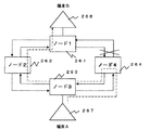
一方、また、図24に示すように、ATMネットワークを構成するノードをリング状に結合したシステムがある。すなわち、複数のノード261〜264を外回りのリング伝送路265と内回りのリング伝送路266で結合し、各ノードには、画像データ、テキストデータ、音声、映像データ等を入出力するカメラやパーソナルコンピュータ等の端末(A)267、端末(B)268を接続し、例えば端末(A)267から端末(B)268に対して画像データやテキストデータ等をATMネットワークで送信するシステムである。ここで、各ノード261〜264は、64Kbps,1.5Mbps,2Mbps等の既存のSTM回線インタフェース部とATM交換機を備えるものである。
【0007】
このようなリング状伝送路で結合されたATMネットワークにおいて、通常は、端末(A)267から端末(B)268へデータを送信する場合、図中に破線で示すように一方のリング伝送路(図26の例では外回りのリング伝送路264)が用いられる。ここで、図25に「×」印で示すように、端末(A)267から端末(B)268に至る伝送路中の中継ノードであるノード264または中継伝送路中に障害が発生した場合、破線で示すように中継ノード264でループバックが実施され、待機系の内回りのリング伝送路266を経て端末(B)に至る伝送路が確保され、端末(A)267から端末(B)268へのデータが伝送される。
【0008】
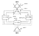
しかし、図26に「×」印で示すように、端末(B)268が接続されているノード261に障害が発生した場合、図26に破線で示すように、ノード264とノード262でループバックが実施され、端末(A)267が出力したデータが図のように端末(A)267に戻ってきてしまう。このため、端末(B)268の障害が検出できず、端末(A)267に障害警報が出力されないという問題がある。
【0009】
これに対し、リング状ネットワークシステムにおける伝送路障害を救済するためのループバックスイッチを用いる方法として、BLSR(Bidrectional Line Switched Ring)という技術がある。このBLSRでは、リングシステム内でノードがどのように接続されているかを示すノード連鎖情報と、回線単位にADD/DROPした信号がどこのノードでアサインされているかを示すスケルチ情報を設定するスケルチテーブルが設けられ、このスケルチテーブルを用いて回線切替を行うようにしている。
【0010】
図30は、そのスケルチテーブルの構成を示すものであり、このスケルチテーブルは、ノード連鎖情報、クロスコネクトタイプ情報、スケルチ情報、WORKLINE情報とで構成されている。
【0011】
ノード連鎖情報は、リングシステム内でノードがどのように接続されているかを表し、クロスコネクトタイプ情報はそのチャンネル即ち、回線の種類を表し、片方向型の回線は1WAY、双方向型の回線は2WAY、インタコネクションのPrimary NODEは2WAYBR、インタコネクション(ON PROT)回線のPrimary NODEは2WAYBRPP、インタコネクション(ON PROT)回線のSecondary NODEは2WAYBRPSとする。
【0012】
スケルチ情報は回線単位にその回線のADD NODE、DROP NODEを示し、それぞれ2ノードが設定できる。特に片方向回線(1WAY)設定時にはADD/DROP NODEと回線の方向性を意識して設定する。WORKLine情報はチャンネル単位にADD/DROPした信号がどこのノード間でWORKラインを使用しているかを表す情報である。また、TOチャンネルとしてプロテクションチャンネル(STBY)も梼成要素に加える。
【0013】
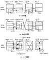
図30に示すスケルチテーブルは伝送路のチャンネル1を用いて図28(a)のインタコネクション回線、チャンネル2を用いて図28(b)のインタコネクション(ON PROT)回線、チャンネル3を用いて図29(c)のブロードキャスト回線を設定している例である。尚、図27(a)に示す一般的な回線の場合もこのスケルチテーブルを使用して設定できる。
【0014】
このスケルチテーブルはノード別に示されているが、その中の図31(d)に示すノード4のスケルチテーブルを使用しての設定状態を説明する。インタコネクション回線(チャンネル1)、インタコネクション(ON PROT)回線(チャンネル2)でWEST側のTOチャンネル1,2のスケルチ情報には、ADDNODE(1)にPrimary NODEであるノート3(NODE3)を設定し、ADD NODE(2)にSecondary NODEであるノード2 (NODE2)を設定し、DROP NODE1に終端であるノード1(NODE1)を設定する。さらにEAST側のTOチャンネル1、2のスケルチ情報にはADD NODE(1)にノード1(NODE1)、DROP NODE(1)にノード3(NODE3)、DLOP NODE(2)にノード2(NODE2)が設定されている。
【0015】
ブロードキャスト回線は、1WAY回線の組み合わせとしてスケルチテーブルに設定する。このブロードキャスト回線は終端ノードであるノード3、ノード4でノード障害が先生してもミスコネクションは発生しないため、スケルチ情報のDROP NODEは最長の終端ノードであるノードド2を設定する。従って、スケルチテーブルは、EAST側のTOチャンネル3のスケルチ情報のADD NODE(1)にノード1(NODE1)、DROP NODE(1)に最長の終端ノードのノード2(NODE2)を設定する。
【0016】
前述したように図28は各種回線例を示したものであるが、この中の(a)インタコネクション回線と(b)インタコネクション(ON PROT)回線との相違はノード3とノード2との間の回線をWORKチャンネルを使用するかSTBYチャンネルを使用するかの逢いで、後者は特にノード2がプロテクションを要しない場合など、STBYチャンネルを使用することによりWORKチャンネル側を空けて他の用途に使用できるようにし、回線の使用効率を上げたものである。またノード3のサービスセレクタSS31は、トリピスクリからの信号とラインからの信号を回線単位で選択するもので、このSS31で回線分岐するノードをプライマリノード、また分岐先ノードをセコンダリイノードと呼杯する。
【0017】
伝送路障害があった場合、各回線はループバックスイッチを行うがこの回線例ではミスコネクションは発生しない。またノード障害に対しても1ケのノード障害に対してはミスコネクションは発生しないが、2ケのノードが障害となるとミスコネクションが発生する。
【0018】
図29を参照してこの場合のミスコネクションに対する対応方法を説明する。
【0019】
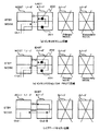
図29は、ノード3とノード2とにノード障害が同時に発生し、ノード3、ノード2に隣接するノード4、ノード1で伝送路の救済処理を開始する。ノード4、ノード1は従来と同じ障害ノードの検出方法によってノード3、ノード2が同時にノード障害となったことを認識する。ノード4はスケルチテーブルのWORKチャンネルのスケルチ情報を参照して、ノード障害となったノード3、ノード2と通信しているパスがあるか否かを検索する。STBYチャンネルは伝送路の救済時のために使用されるため検索する必要はない。
【0020】
その結果、スケルチテーブルでTOチャンネルがWEST(WORK)−1。WEST(WORK)−2,EAST(WORK)−1、EAST(WORK)−2,EAST(WORK)−3を発見する。ADD NONE(1)、ADDNODE(2)またはDROP NODE(1)、DROP NODE(2)が同時に設定されている場合、そのパスはインタコネクションのために使用されているため、ADD NODE(1),ADD NODE(2)またはDROPNODE(1),DROP NODE(2)が同時にノード障害となったと認識したとき、ミスコネクションが発生する可能性のあるチャンネルと認識する。
【0021】
従って、この例では、WEST(WORK)−1,WEST(WORK)−2,EAST(WORK)−1,EAST(WORK)−2が上記条件に当てはまるためチャンネルにPATH AISを挿入することを決定する。
【0022】
EAST(WORK)一3はDROP NODE(1)にノード2が設定されているが1WAYパスであるためPATH AISを挿入対象チャンネルとしない。実際にPATH AISを挿入する方法については、「ADD NODE」に障害ノードを発見した場合には、そのWORKチャンネルに対してPATH AIS201を挿入し、「DROP NODE」に障害ノードを発見した場合にはSTBYチャンネルに対してPATH AIS202を挿入する。
【0023】
従ってこの例では、図31(2)においてWEST(WORK)−1、WEST(WORK)−2とWEST(STBY)−1,WEST(STBY)一2にPATH AIS301,302を挿入する。このミスコネクション防止の処理が終わった後に、ループバックスイッチを行って伝送路の救済を行う。
【0024】
【発明が解決しようとする課題】
しかしながら、上記特開平5−63761号公報に開示された方法にあっては、送信側と受信側との間で、時間情報が正常に受信されたか、受信されなかったのかを常に確認し合うためのプロトコルが必要になる。このため、送信側と受信側に具備させるプロトコルが複雑になるという問題がある。
【0025】
一方、OAMセルを用いて対向ATM交換機との間の導通試験、性能試験、警報通知を行なう方法にあっては、一方のATM交換機のセル分解組立て部と他方のATM交換機のセル分解組立て部との間の回線障害しか検出することができず、セル化する前の通信路部分とデセル化した後の通信路部分との間にまで範囲を広げて回線の正常または異常を検出することができないという問題がある。
【0026】
また、回線より受信した警報情報のOAMセルは、ユーザデータ(ペイロードデータ)セル流と多重して転送されるが、警報内容に変化が無い時でも常にユーザデータに多重化されて転送されるため、ーザデータ伝送効率を低下させるという問題がある。
【0027】
また、リング伝送路を用いたATMネットワークシステムにおいて、対向ノートで障害が発生した場合、その障害が発生した対向ノードの手前で伝送路がループバックされるため、(1)自ノードで出力したデータが該ループバック点で折り返されて自ノードに戻ってきてしまい、対向装置が断となっても障害が検出されないという問題と、(2)図27〜図31で説明したように、ループバック時にミスコネクションにP・AISを出力する方法では、ATMセルまたはパケット等の論理コネクションには対応できないという問題がある。
【0028】
本発明は、送信側および受信側の装置に複雑なプロトコルを具備させることなく、回線障害を検出することができる回線障害検出方法および装置を提供することを第1の目的とする。
【0029】
また、本発明は、セル化する前の通信路部分とデセル化した後の通信路部分との間にまで範囲を広げて回線の正常または異常を検出することができる回線障害検出方法を提供することを第2の目的とする。
【0030】
また、本発明は、ユーザデータの伝送効率の低下を最小限に抑え、警報情報を転送することができる警報情報転送方法を提供することを第3の目的とする。
【0031】
さらに、本発明は、リング状ネットワーク構成における対向装置で障害が起きてもATMコネクション/パケットコネクションレベルで自ノードで対向装置の障害を検出し、端末にその障害情報を出力することができる回線障害検出方法を提供すること第4の目的とする。
【0032】
【課題を解決するための手段】
上記目的を達成するため、請求項1の発明は、回線インタフェースから入力されたデータを固定ビット長のデータに組立て、送信先に向けて送信する通信システムにおける回線障害検出方法であって、送信側装置において回線インタフェースから入力されたデータをペイロード部分と警報データ部分とに分離した後、警報データ部分に誤り検出符号を付加し、その誤り検出符号が付加された警報データ部分と前記ペイロード部分とを同一送信単位の固定長データに組立てて送信先に送信し、受信側装置において送信側から受信した固定長データをペイロード部分と警報データ部分とに分離し、その分離した警報データ部分の誤りの有無を該警報データ部分に付加された誤り検出符号によって検出し、警報データ部分に誤りが無ければ、受信したペイロード部分と警報データ部分とを同一送信単位の固定長データに組立てて受信端回線インタフェースに送出し、警報データ部分に誤りが有れば回線障害が発生したものと判定し、回線断の警報データを受信端回線インタフェースに送出することを特徴とする。
【0033】
また、請求項2の発明は、請求項1の発明において、警報データ部分の誤りが予め設定した値以上にわたって連続した場合に前記回線断の警報データを送出し、設定値未満の場合は誤りが無かった最後の警報データを受信端回線インタフェースに送出することを特徴とする。
【0034】
また、請求項3の発明は、請求項1または2の発明において、送信側から受信した固定長データを順次格納する受信バッファのアンダフローを検出し、予め設定した時間以上にわたってアンダフローが検出された場合は回線断の警報データを受信端回線インタフェースに送出することを特徴とする。
【0035】
また、請求項4の発明は、請求項1〜3の発明において、前記警報データ部分は、警報内容の変化時のみ受信端回線インタフェースに送出することを特徴とする。
【0036】
また、請求項5の発明は、請求項1〜4の発明において、前記警報データ部分に付加する誤り検出符号の算出式をペイロード部分の双方向パスの上り/下り方向に応じて異ならせることを特徴とする。
【0037】
また、請求項6の発明は、回線インタフェースから入力されたデータを固定ビット長のデータに組立て、送信先に向けて送信する通信システムにおける回線障害検出方法であって、送信側装置において回線インタフェースから入力されたデータをペイロード部分と警報データ部分とに分離した後、警報データ部分に誤り検出符号を付加し、その誤り検出符号が付加された警報データ部分と前記ペイロード部分とを同一送信単位の固定長データに組立てて異なるコネクションで送信先に送信し、受信側装置において送信側から受信した固定長データをペイロード部分と警報データ部分とに分離し、その分離した警報データ部分の誤りの有無を該警報データ部分に付加された誤り検出符号によって検出し、警報データ部分に誤りが無ければ、受信したペイロード部分と警報データ部分とを同一送信単位の固定長データに組立てて受信端回線インタフェースに送出し、警報データ部分に誤りが有れば回線障害が発生したものと判定し、回線断の警報データを受信端回線インタフェースに送出することを特徴とする。
【0038】
また、請求項7の発明は、回線インタフェースから入力されたデータを固定ビット長のデータに組立て、送信先に向けて送信する通信システムにおける回線障害検出方法であって、送信側装置において回線インタフェースから入力されたデータをペイロード部分と警報データ部分とに分離し、警報データ部分に対し双方向パスの上り/下り方向に応じて異なる算出式の誤り検出符号を付加し、その誤り検出符号が付加された警報データ部分と前記ペイロード部分とを固定長データに組立てて送信先に送信した後、送信先の装置からの下り方向パスによるデータ受信を待ち、下り方向パスでデータを受信したならば、その受信データの誤り検出符号の算出式が下り方向に対応しているか否かを判定し、下り方向に対応している場合は受信データ中の警報データ部分に付加された誤り検出符号によって警報データ部分の誤りの有無を検出し、送信側装置が送信したデータがループバックして下り方向パスで当該送信側装置に戻って来た場合は、誤り検出符合の算出式の不一致によって送信先装置に障害が発生したものと判定し、送信先の装置においては、送信側から受信した固定長データの警報データ部分の誤りの有無を該警報データ部分に付加された上り方向の算出式の誤り検出符号によって検出し、誤りが有れば回線障害が発生したものと判定し、回線断の警報データを受信端回線インタフェースに送出することを特徴とする。
【0039】
また、請求項8の発明は、請求項7の発明において、送信側から受信した固定長データを順次格納する受信バッファのアンダフローを検出し、予め設定した時間以上にわたってアンダフローが検出された場合は回線断の警報データを受信端回線インタフェースに送出することを特徴とする。
【0040】
また、請求項9の発明は、回線インタフェースから入力されたデータを固定ビット長のデータに組立て、送信先に向けて送信する通信システムにおける回線障害検出方法であって、送信側装置において回線インタフェースから入力されたデータをペイロード部分と警報データ部分とに分離し、警報データ部分に対し双方向パスの上り/下り方向に応じて異なる算出式の誤り検出符号を付加し、その誤り検出符号が付加された警報データ部分と前記ペイロード部分とを固定長データに組立てて異なるコネクションで送信先に送信した後、送信先の装置からの下り方向パスによるデータ受信を待ち、下り方向パスでデータを受信したならば、その受信データの誤り検出符号の算出式が下り方向に対応しているか否かを判定し、下り方向に対応している場合は受信データ中の警報データ部分に付加された誤り検出符号によって警報データ部分の誤りの有無を検出し、送信側装置が送信したデータがループバックして下り方向パスで当該送信側装置に戻って来た場合は、誤り検出符合の算出式の不一致によって送信先装置に障害が発生したものと判定し、送信先の装置においては、送信側から受信した固定長データの警報データ部分の誤りの有無を該警報データ部分に付加された上り方向の算出式の誤り検出符号によって検出し、誤りが有れば回線障害が発生したものと判定し、回線断の警報データを受信端回線インタフェースに送出することを特徴とする。
【0041】
また、請求項10の発明は、回線インタフェースから入力されたデータを固定ビット長のデータに組立て、送信先に向けて送信する通信システムにおける伝送装置であって、送信側の伝送装置は、回線インタフェースから入力されたデータをペイロード部分と警報データ部分とに分離する手段と、分離された警報データ部分に誤り検出符号を付加する手段と、誤り検出符号が付加された警報データ部分と前記ペイロード部分とを同一送信単位の固定長データに組立てて送信先に送信する手段とを備え、受信側の伝送装置は、送信側伝送装置から受信した固定長データをペイロード部分と警報データ部分とに分離する手段と、分離した警報データ部分の誤りの有無を該警報データ部分に付加された誤り検出符号によって検出し、警報データ部分に誤りが無ければ、受信したペイロード部分と警報データ部分とを同一送信単位の固定長データに組立てて受信端回線インタフェースに送出し、警報データ部分に誤りが有れば回線障害が発生したものと判定し、回線断の警報データを受信端回線インタフェースに送出する手段とを備えることを特徴とする。
【0046】
【発明の実施の形態】
以下、この発明に係わる回線障害検出方法の一実施の形態を添付図面を参照して詳細に説明する。
【0047】
図1は、この発明を適用する通信システムの一実施の形態を示す構成図であり、最も簡単な構成例として、ATM交換機1と2とをATMクロスコネクタ(VPH)等の交換機間接続装置3、4によって接続した構成を示している。
【0048】
各ATM交換機1,2には、複数のDSU(Digital Service Unit;ディジタル回線終端装置)が5−1〜5−n,6−1〜6−nが接続され、これらのDSU5−1〜5−n,6−1〜6−nにはコンピュータ7、9や電話機8が端末装置として接続され、テキストデータや映像、音声などのデータを交換するようになっている。
【0049】
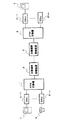
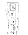
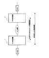
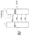
図2は、ATM交換機1、2内に設けられる回線インタフェース部の送信部の詳細構成の一実施形態を示すブロック構成図であり、回線データ受信部101、ペイロード/警報データ分離部102、誤り検出符号付与部103、セル/パケット組立て部104、セル/パケット送信部105とを備え、回線データ受信部101にはDSUを介してコンピュータ7などの端末装置からのデータが入力される。
【0050】
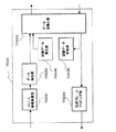
図3は、ATM交換機に設けられる回線インタフェース部の受信部の詳細構成の一実施形態を示すブロック構成図であり、回線障害検出部106、セル/パケット分解部107、ペイロードデータ/警報データ分離部109、誤り検出部110、回線断警報出力部111、ペイロードデータ/警報データ合成部112、回線データ送出部113とを備えている。
【0051】
このような構成において、ATM交換機1を送信側装置、ATM交換機2を受信側装置であると仮定した場合、送信側のATM交換機1の回線インタフェース部は例えばDSU5−1から入力されたデータを回線データ受信部101で受信し、ペイロードデータ/警報データ分離部102に入力する。ペイロードデータ/警報データ分離部102は、入力されたデータをペイロード部分と警報データ部分とに分離する。
【0052】
ここで、警報データとは、回線断、同期外れなどの回線障害を示す情報であり、回線受信端で検出した情報である。
【0053】
ペイロードデータ/警報データ分離部102は、分離したペイロードデータはセル/パケット組立て部104に入力し、警報データは誤り検出符号付与部103に入力する。誤り検出符号付与部103は、入力された警報データ部分に誤り検出符号を付加し、セル/パケット組立て部104に入力する。セル/パケット組立て部104は、誤り検出符号が付加された警報データ部分とペイロードデータ/警報データ分離部102が分離したペイロード部分とを1つのセル/パケットに組立ててセル/パケット送信部105から送信先のATM交換機2に送信する。この場合、セル化はITU−T I.363.1の基準に従う。
【0054】
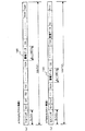
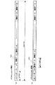
また、警報データの送信の仕方ついては、図4に示すように、1つのコネクションで送信するようにしてもよいし、図5および図6に示すように、別のコネクションで送信するようにしてもよい。なお、図4〜図6において、SNはシーケンス番号、SHはSARヘッダバイト、SPはストラクチャポインタバイト、TS1〜TS93はペイロードを構成する8ビットのデータである。警報データ120は、8ビットまたは16ビットのデータで構成される。
【0055】
これに対し、受信側のATM交換機2は、送信側からのATMセル回線障害検出部106とセル/パケット分解部107で受信する。回線障害検出部106は、ネットワークの入り口の回線障害、例えば回線断、フレーム同期外れ等を検出し、回線断警報出力部111に報告する。
【0056】
一方、セル/パケット分解部107は、受信したセルの分解を行ない、ペイロードデータ/警報データ分離部109に入力する。ペイロードデータ/警報データ分離部109は、受信したセルをペイロード部分と警報データ部分とに分離し、その分離した警報データ部分を誤り検出部110に入力する。誤り検出部110は、警報データ部分の誤りの有無を該警報データ部分に付加された誤り検出符号によって検出し、その検出結果を回線断警報出力部111に入力する。
【0057】
一方、アンダフロー検出部108は、セル/パケットを受信する受信バッファのアンダフローを検出し、予め設定した時間以上にわたってアンダフローが検出された場合は、このことを回線断警報出力部111に報告する。
【0058】
回線断警報出力部111は、誤り検出部110における検査の結果、警報データ部分に誤りが無ければ、受信したペイロード部分と警報データ部分とをペイロードデータ/警報データ合成部112において同一送信単位の固定長データであるセルに組立てさせて回線データ送出部113から受信端回線インタフェースに送出する。
【0059】
しかし、警報データ部分に誤りが有れば回線障害が発生したものと判定し、回線断の警報データを回線データ送出部113から受信端回線インタフェースに送出させる。
【0060】
また、回線断警報出力部111は、アンダフロー検出部108が予め設定した時間以上にわたってアンダフローを検出した場合にも、回線断の警報データを回線データ送出部113から受信端回線インタフェースに送出させる。さらに、回線障害検出部106がネットワークの入り口の回線障害、例えば回線断、フレーム同期外れ等を検出した場合にも、回線断の警報データを回線データ送出部113から受信端回線インタフェースに送出させる。
【0061】
このように、警報データに対し誤り検出符号を付加して受信側に送信し、受信側において誤り検出符号によって警報データの誤りの有無を検査し、誤りがある場合は、回線断の警報データを受信端回線インタフェースに送出させることにより、送信側装置と受信側装置に回線の状態を確認し合うためのプロトコルを設ける必要がなくなり、プロトコルが複雑化するのを防止でき、回線の異常を簡単に検出することができる。
【0062】
なお、警報データに誤りがあった場合に、直ちに回線断の警報データを出力するようにしているが、誤りが予め設定した値以上にわたって連続した場合に回線断の警報データを出力し、設定値未満の場合は誤りが無かった最後の警報データのみを出力するようにしてもよい。
【0063】
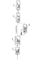
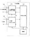
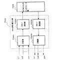
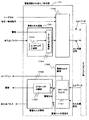
図7は、本発明の第2の実施の形態を示すATM交換機の構成を示すブロック図である。この実施形態のATM交換機701は、6.3Mbpsの既存回線706を収容する6.3M既存回線インタフェース部702と、ATM網707を収容するATM網インタフェース部703と、ATMセルのルーティングを行なうATMスイッチ部704と、全体を制御する制御部705とを備えている。
【0064】
6.3M既存回線インタフェース部702に入力された映像やテキストなどのデータは、この6.3M既存回線インタフェース部702で回線伝送フレームの終端が行われ、53バイトのATMセルに変換され,ATMスイッチ部704に送出される。ATMスイッチ部704は、入力されたATMセルのセルヘッダにより予め設定されたATM網インタフェース部703へ転送する。
【0065】
ATM網インタフェース部703へ入力されたATMセルは、ATM網707を介して対向のATM交換機へと転送され、対向側の6.3M既存回線へとルーティングされる。
【0066】
図8に6.3M既存回線インタフェース部702の詳細構成を示している。 図示する6.3M既存回線インタフェース部702は、回線インタフェース部7021、フレーム終端部7022、セル分解・組立て部7023、ATMスイッチインタフェース部7024を備えている。
【0067】
6.3M既存回線706から入力されたデータは、回線インタフェース部7021で光/電気変換、伝送符号変換され、次のフレム終端部7022で6.3Mフォーマットにアサインされたデータ流のフレーム同期ビッートによりフレーム同期、伝送フレームからのデータの抽出が行なわれる。抽出されたデータはセル分解・組立て部7023で予め設定されたVPI(仮想パス番号),VCI(仮想チャンネル番号)の5バイトのセルヘッダが付加された53バイトのATMセルに変換される。ATMセルは,ATMスイッチインタフェース部7024を介してATMスイッチ部704ヘ入力される。
【0068】
図9は、フレーム終端部7022の詳細構成を示すブロック図であり、図示するフレーム終端部7022は、フレーム同期処理部70221、データ抽出部70222、データ切換え部70223、伝送フレームマッピング部70224、試験データ発生部70225、試験データ比較部70226を備え、ATM通信システムの運用開始前または運用中の障害発生時に、試験データ発生部70225から試験データを発生させ、設定された回線を経由して対向する回線インタフェース部の回線終端部に向けて送信し、この対向する回線終端部を経由して戻ってきた試験データと送信した試験データとを試験データ比較部70226で比較し、その異同によって対向する回線インタフェース部の回線終端部に到る回線の異常の有無を検出するように構成されている。
【0069】
ここで、試験データ発生部70225は、固定長のランダムデータを繰り返し発生する構成となっている。試験データ発生部70225から発生された試験データは、ATM通信システムの運用開始前または運用中の障害発生時に、データ切換え部70223の入力がデータ抽出部7022側から試験データ発生部70225側へ切り換えられることにより、データ切換え部70223を経由してセル分解・組立て部7023に入力される。そして、セル分解・組立て部7023でATMセルに変換され、対向のATM交換機の回線インタフェース部の回線終端部に向けて送信される。
【0070】
対向のATM交換機における回線インタフェース部の回線終端部は、受信した試験データを逆の経路で送信元の回線終端部7022に送り返す。
【0071】
これに対し、データ切換え部70223を経由して戻って来た試験データを受信した試験データ比較部70226は、試験データ発生部70225が送信した試験データと戻って来た試験データとを比較し、両者が不一致であれば、対向のATM交換機の回線インタフェース部の回線終端部に到る経路に回線異常があるものと判定し、ATM交換機701の制御部705に通知する。しかし、一致している場合は、回線は正常であるものとして制御部705に通知する。
【0072】
なお、データ切換え部70223は、制御部705からの切り換えコマンドにより、通常はデータ抽出部70222と伝送フレームマッピング部70224に接続されている。
【0073】
このように、通信システムの運用開始前または運用中の障害発生時に、試験データ発生部70225から試験データを発生させ、設定された回線を経由して対向する回線インタフェース部の回線終端部に向けて送信し、この対向する回線終端部を経由して戻ってきた試験データと送信した試験データとを試験データ比較部70226で比較し、その異同によって対向する回線インタフェース部の回線終端部に到る回線の異常の有無を検出することにより、OAMセルでは実現できなかったエンド・エンドでの通話路の正常性の確認を試験器等を接続することなく行うことができる。
【0074】
すなわち、図10に示すように、OAMセルを用いた回線の確認範囲は、セル分解・組立て部までであるが、上記のように構成することにより、フレーム終端部までの範囲に拡大し、デセル化された部分までを含めた回線の正常・不正常の確認を行なうことが出来る。
【0075】
図11は、セル分解・組立て部7023の詳細構成を示すブロック図であり、図示するセル分解・組立て部7023は多重部70231、AAL1送信部70232、AAL1受信部70234、分離部70235とを備え、固定ビットレート(CBR)でデータを送受する構成になっている。
【0076】
従来、複数回線の固定ビットレートの信号を多重する場合は、入力する回線の帯域が例えば、1.536Kbps(24TS)の場合、そのうちの例えば384Kbps(6TS)のみ使用するときも、1.536Kbps分だけ多重化している。このため、伝送効率(スループット)が低い上、システム全体のトラフィックが大きくなり、その他の回線を増やすことが難しくなるという問題があった。
【0077】
また、低速の場合(例えば、64Kbps)、セル化するのに約6msかかるため、電話等の即時性を要求される回線では伝送遅延が問題になり、より速くセル化することが望まれていた。
【0078】
図11のセル分解・組立て部7023は、このような問題を解決する機能を新たに設けたものである。すなわち、使用する帯域が入力する回線帯域より小さい場合は、使用する帯域部分だけを多重化することにより、システムのトラフィックを低くし、また、回線数の増加を容易に可能にする。さらに、複数回線上の使用帯域をまとめて1ブロックとしてセル化することにより、1つの回線での使用帯域分をセル化するより速くセル化するようにしたものである。以下、詳しく説明する。
【0079】
図11において、多重部70231は、受信回線Li1〜Linからのデータを入力し、多重化して出力する。次のAAL1送信部70232は、多重化されたデータをITU−T I.432に規定された基準に従い、セル化してATMスイッチインタフェース部7024に出力する。
【0080】
一方、ATMスイッチインタフェース部7024から受信したATMセルは、AAL1受信部70234でITU−T I.432に規定された基準に従い、デセル化され、分離部702355で各回線Lo1〜Lonに分離されて出力される。
【0081】
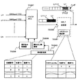
図12は、セル分解・組立て部7023の組立側の詳細な構成を示す図であり、受信回線Li1〜Linから入力されたCBRデータは、多重部70231内のバッファメモリ70237の各回線毎に割り当てられた領域に、書き込み制御部70238によって回線番号順に書き込まれる。ここで、帯域設定部70240が設けられ、各回線毎に使用する帯域のタイムスロット(TS)の先頭値と最終値とが予め設定されている。図12の例では、「回線番号1」のデータは、TS=1〜6までを使用することが設定されている。
【0082】
読み出し制御部70239は、設定された各回線のタイムスロットの値にしたがってバッファメモリ70237に格納された受信回線Li1〜LinからのCBRデータを読み出し、多重化する。これによって、「回線番号1」のCBRデータAは、1フレームの中のTS=1〜6に多重化されてAAL1送信部70232に入力され、ここでITU−T I.432に規定された基準に従いセル化される。
【0083】
図13は、受信回線Li1〜Linが64Kbpsの帯域の場合の多重化の様子を示す図である。ここで示す例は、帯域設定部70240における帯域設定を受信回線LiについてTSの先頭値を1、最終値を1、次の受信回線Li1+1についてTSの先頭値を2、最終値を2とし、受信回線からのデータを2TS毎にバッファメモリ70237に蓄積していき、さらに、AAL1送信部70232内のコネクション設定部70241でセル化の先頭値=1,最終値=2とし、1回線毎に2TSを1ブロックとしてセル化する場合を示している。このようにすることによって、1TSごとに蓄積していく場合の半分の時間でセル化が可能になる。
【0084】
図14は、セル分解・組立部7023の分解側の詳細な構成を示す図である。
【0085】
ATM交換機から受信したセルは、AAL1受信部70232でITU−T I.432に規定された基準に従いデセル化される。デセル化されたデータは、分離部70235内のバッファメモリ70245に書き込み制御部70246によって書き込まれる。帯域設定部70248には、予め各回線毎に使用する帯域のTSの先頭値と最終値および回線の伝送帯域が設定されている。そこで、読み出し制御部70247は帯域設定部70248に設定された各回線のタイムスロットの値にしたがってバッファメモリ70245に格納されたデータを読み出し、分離する。
【0086】
例えば、回線番号=1について、その使用帯域が384Kbps(6TS)で伝送帯域が1.536Mbps(24TS)の場合、使用帯域の方が伝送帯域より小さいため、6TSのデータを読み出した後、帯域設定部70248に設定されている回線番号=1の伝送帯域と使用帯域の差から18TS分をデータ付加部70249から固定データとして読み出し、回線番号=1に対応するセレクタ70250に入力し、18TS分の固定データを6TSのデータに付加して回線番号=1の回線から出力させる。
【0087】
これによって、デセル化されたデータの帯域も回線毎に制御することが出来る。
【0088】
そして、伝送効率(スループット)を高くすることができ、収容回線のトラフィックが小さくなったことにより、回線の増設が容易になる。更に、2つ以上の回線のデータを1ブロックにしてセル化することにより電話等の即時性を要求される回線では伝送遅延の問題を解消することが可能になる。
【0089】
次に、ユーザデータの伝送効率の低下を最小限に抑えて警報情報を転送する実施形態について説明する。
【0090】
図15は、ATM交換機の回線インタフェース部の他の実施形態を示すブロック図である。この実施形態の回線インタフェース部は図7の6.3M既存回線インタフェース部に設けけられるものである。
【0091】
図15に示す回線インタフェース部は、6.3M回線フレーム終端部171、警報検出/挿入部172、セル化/デセル化部173、警報情報セル挿入/検出部174とから構成されている。
【0092】
6.3M既存回線からのデータは、図7の実施形態と同様にして6.3M回線フレーム終端部171で回線伝送フレームの終端が行われ、警報検出/挿入部172でフレームの特定ビットから警報情報が検出され、ユーザデータ(ペイロード)と警報情報データとに分離される。
【0093】
次段のセル化/デセル化部173へはユーザデータのみが転送され、予め設定されたVPIとVCIが付加され、53バイトのATMセルとして警報情報セル挿入/検出部174へ送出される。警報情報セル挿入/検出部174では、警報検出/挿入部172からの警報情報を元に指定のペイロードタイプ値のATMヘッダを付加し、このATMヘッダの付加された警報データをユーザデータセル流の無効セルの位置に挿入し、ATMスイッチ部(図7の704に相当)ヘと転送する。
【0094】
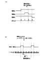
図16は、警報検出/挿入部172と警報情報セル挿入/検出部174の入出力関係を抽出した図であり、回線の状態や保守情報としての警報情報として、警報A、B、Cを転送する場合を例に示している。
【0095】
回線側からの警報A.B,Cは警報検出/挿入部172で監視されており、れそれぞれの警報内容が変化した時点で、図20(A)のタイムチャートに示すように、警報内容が変化したことを示す警報変化点パルスが警報検出/挿入部172から出力される。なお、図20では、警報A,B,Cの変化をパルスで示しているが、警報そのものがパルスであることを示しているものではない。
【0096】
変化点パルスと響報A,B,Cは、警報情報セル挿入/検出部174へ転送され、図20(B)のタイムチャートに示すように、警報変化点パルスが“1”のときの警報A.B.Cの状態がセルのペイロード部分となり、所定のペイロードタイプ値と予め設定されたVPI、VCI値が付加されATMセルとなる。
【0097】
このATMセルはセル化/デセル化部173からのユーザデータセル流と有効/無効セル表示信号により無効セルの位置に挿入され、ATMスイッチ部ヘと送出される。
【0098】
この場合、警報変化点での警報情報セルの送出数は、システムの信頼性の観点から、ネットワーク上でのセル損失を考慮して、任意に設定できるものである。
【0099】
図17に、回線フレーム終端部171、警報検出/挿入部172、セル化/デセル化部173の入出力関係を示し、図18に警報検出/挿入部172の内部のデータ/警報分離部1721、データ/警報多重部1722の詳細構成を示している。
【0100】
図18に示すように、データ/警報分離部1721の出力側には、分離した警報データの変化点を抽出し、変化点パルスとして出力する警報変化点抽出部1723が設けられている。また、データ/警報多重部1722の入力側には、対向装置から受信した警報データを変化点パルスが変化した時点で取り込んで更新する警報状態更新部1724が設けられている。
【0101】
図19は、警報情報セル挿入/検出部174の詳細構成を示すブロック図であり、警報セル生成部1741、セル多重部1742、警報セル分離部1746、警報セル分解部1745とを備え、警報変化点パルスが“1”のときの警報の状態がセルのペイロード部分となり、ATMヘッダ生成部1743で生成された所定のペイロードタイプ値と予め設定されたVPI、VCI値がATMヘッダ多重部1744で付加され、ATMセルとなってセル多重部174に入力される。
【0102】
このATMセルはセル化/デセル化部173からのユーザデータセル流と有効/無効セル表示信号により無効セルの先頭位置に挿入され、ATMスイッチ部ヘと送出される。
【0103】
一方、ATMスイッチ部から入力されたセルは警報セル分離部1746のVPI/VCIフィルタ1747でフィルタリングされ、ユーザセルと警報セルに分離される。分離された警報セルは、警報セル先頭表示信号により警報セル分解部1745のATMヘッダ分離部1748でヘッダ部分が分離されて警報データとして出力される。
【0104】
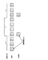
図21に、従来技術と本発明での警報報情報セルの転送形態の相違を示す。従来は警報情報をセル化/デセル化部173へ転送し、指定のATMヘッダを付加し警報情報の値をそのままセル化するようにしていたため、図21に示すように、警報内容の変化の有無に関わらず、常時、セルを転送し続ける形態となる。しかし、実際の連用形態では警報情報はほとんど変化することなく異常が発生した場合や保守運用の必要がある場合のみ変化するものであるため、同一の値をセルとして転送することとなる。
【0105】
本発明では、図21に示すように、この警報情報の内容に変化のあった場合のみセルを発生させ、その状態を変化させる形態とする。
【0106】
これにより、ユーザデータの伝送効率の低下を最小限に抑えて警報情報を転送することができる。なお、このような警報情報の転送形態は、図1や図7で示した実施形態にも同様に適用することができる。
【0107】
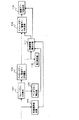
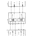
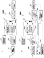
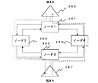
次に、リング状伝送路でATMセルを送受信する場合に、対向装置で障害が起きてもATMコネクション/パケットコネクションレベルで自ノードで対向装置の障害を検出し、端末にその障害情報を出力することができる回線障害検出方法の実施形態について図22(a),(b)を用いて説明する。
【0108】
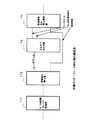
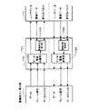
図22(a)は、ATM交換機の回線インタフェース部の送信部の構成を示すブロック図、同図(b)は受信部の構成を示すブロック図である。図22(a)において、240は入力端子であり、回線データが入力される。回線データ受信部241は、図2の実施形態と同様にして入力端子240からの回線データを受信し、ペイロードデータ/警報データ分離部242にフレームデータを出力する。
【0109】
ペイロードデータ/警報データ分離部242は、受信したフレームデータから警報データとペイロードデータとをそれぞれ分離する。誤り検出選択制御回路243は、警報データに付与する誤り検出符号の算出式をパスの上り方向/下り方向により異なるものを選択する。
【0110】
すなわち、図23のようなリング状伝送路において、端末(A)267から端末(B)268への上り方向の通信パスでは誤り符号タイプ(A)の算出式で算出した誤り検出符号を選択する。一方、端末(B)268から端末(A)267への下り方向の通信パスではノード261内のATM交換機において誤り符号タイプ(B)の算出式で算出した誤り検出符号を選択するようにする。
【0111】
このように誤り検出符合を双方向パスの上り方向と下り方向で異ならせることにより、対向ノードに障害が発生して自ノードから送信したセルがループバックされて自ノードに戻ってきても誤り検出符号の計算式が異なるため、対向側のノードで障害が発生したものとして検出することができる。
【0112】
誤り検出符号付与部244a,244bでは、ペイロードデータ/警報データ分離部242で抽出分離された警報データに誤り検出符号を付加し、選択部245に結果を出力する。ここで、誤り検出符号付与部244a,244bでは、誤り検出符号の計算式が異なる。
【0113】
選択部245では、誤り符号選択制御部243で選択された誤り検出符号を選択し、セル/パケットアセンブリ部246に出力する。セル/パケットアセンブリ部246は,ペイロードデータと誤り検出符号が付加された警報データを以下の方法でセル/パケットヘのアセンブリを行う。この場合、セル化はITU・TI・363・1のAAL1に従う。
【0114】
ペイロードデータと警報データを、図4に示したように1つのコネクションで伝送ペイロードデータと警報データを、図5、図6に示したように、別のコネクションで伝送セル/パケット伝送部247は、アセンブリされた、セル/パケットを対向のノードの受信部へ転送する。
【0115】
次に、図22(b)に示す受信部について説明する。
【0116】
まず、回線障害検出部258では送信部からネットワークを介して転送されてくるネットワークの入り口の回線障害を監視する。ネットワークの障害(回線断、フレーム同期外れ等)が生じたときには、回線断警報出力部256に通知し、端末で警報を出力する。
【0117】
セル/パケットデアセンブリ部249では、受信したセル/パケットのデアセンブリを行う。この場合のデセル化はITU−TI・363・1のAAL1に従う。
【0118】
アンダフロー検出部250では受信したセル/パケットを蓄積するバッファメモリのアンダフローの有無を監視し、アンダフローが所定の設定時間以上続いた場合には、回線断警報出力部256に通知する。
【0119】
デアセンブリされたデータは、ペイロード/警報データ分離部251において、それぞれへペイロード部と警報部とに分離され、分離された警報データは誤り検出部(1)252a,(2)252bで、送信側の誤り検出符号付与部244aまたは244bで付加された誤り検出符号により誤りの有無を計算する。
【0120】
誤り検出部(1)252a,(2)252bでは、送信部の誤り検出符号付与部244aまたは244bで付加された誤り検出符号に対応した誤り検出符号計算式により誤りを計算している。誤り検出制御部253は、前記送信部と同様に、設定された双方向パスの上り/下り方向により誤り検出回路252aまたは252bの結果を選択するように選択部254に指示を出す。選択部254では選択結果をペイロードデータ/警報データ合成部255、及び回線断出力制御部256に出力する。
【0121】
ペイロードデータ/警報データ合成部255は、合成したデータを回線断警報出力部257に出力する。回線断警報出力部257では、回線断警報出力と送信側からの警報データをそのまま出力する動作を行う。
【0122】
回線断警報出力動作では、以下の3つの通知のどれか1つが通知された場合、またはアンダフロー検出部250のアンダフロー誤りが無く、送信側から回線断の警報が送られた場合、
A)回線障害検出部258からの回線障害の通知
B)アンダフロー検出部250からアンダフロー有りの通知
C)誤り検出部(1)252a,(2)252bからの誤り有りの通知
を行う。
【0123】
一方、ペイロードデータ/警報データ合成部255は、分離部251で分離されたペイロードデータと警報データとを合成して図示しない回線データ出力部から回線データとして回線側に出力する。
【0124】
以上のように、(1)AAL1のアンダフロー、(2)警報データヘの誤り検出符号の付与、(3)受信側のネットワークの入り口の回線断検出を監視することにより、送信側から受信側までの中縦ノード回線に異常が生じたときに受信側で回線断を検出することが可能となる。
【0125】
特に、双方向パスの上り/下り方向に応じて、誤り検出符号を異ならせているため、リング状伝送路でATMセルを送信するネットワークにおいて対向ノードが障害になってループバックがなされて自ノードが出力したデータが折り返ってきた時でも、対向ノードの誤りを確実に検出でき、加えてコネクシヨン毎に対応前記検出が可能になり、該当端末へ対向装置の障害を出力することができる。
【0126】
なお、誤り検出符号の計算式を上り方向と下り方向で異ならせる方法は、図1や図7の実施形態にも適用することができる。
【0127】
【発明の効果】
以上のように本発明によれば、送信側および受信側の装置に複雑なプロトコルを具備させることなく、回線障害を検出することができる。
【0128】
また、セル化する前の通信路部分とデセル化した後の通信路部分との間にまで範囲を広げて回線の正常または異常を検出することができる。
【0129】
また、ユーザデータの伝送効率の低下を最小限に抑え、警報情報を転送することができる。
【0130】
さらに、リング状ネットワーク構成における対向装置で障害が起きてもATMコネクション/パケットコネクションレベルで自ノードで対向装置の障害を検出し、端末にその障害情報を出力することができる。
【図面の簡単な説明】
【図1】この発明を適用するATM通信システムの一実施の形態を示す構成図。
【図2】図1のATM交換機内に設けられる回線インタフェース部の送信部の詳細構成の一実施形態を示すブロック構成図。
【図3】図1におけるATM交換機に設けられる回線インタフェース部の受信部の詳細構成の一実施形態を示すブロック構成図。
【図4】警報データを1つのコネクションで送信する場合のマッピング図。
【図5】警報データとペイロードデータとを別のコネクションで送信する場合のペイロードデータのマッピング図。
【図6】警報データとペイロードデータとを別のコネクションで送信する場合の警報データのマッピング図。
【図7】本発明の第2の実施形態を示すATM交換機の構成図。
【図8】図7における6.3M既存回線インタフェース部の詳細構成図。
【図9】図8におけるフレーム終端部の詳細構成図。
【図10】図9の構成を使用した場合の通信路の確認可能範囲を示す説明図。
【図11】セル分解・組立て部の詳細構成図。
【図12】セル分解・組立て部の組立側の詳細な構成を示す図。
【図13】受信回線Li1〜Linが64Kbpsの帯域の場合の多重化の様子を示す図。
【図14】セル分解・組立部の分解側の詳細な構成を示す図。
【図15】ATM交換機の回線インタフェース部の他の実施形態を示すブロック図。
【図16】警報検出/挿入部と警報情報セル挿入/検出部の入出力関係を抽出した図。
【図17】回線フレーム終端部、警報検出/挿入部、セル化/デセル化部の入出力関係を示す図。
【図18】警報検出/挿入部の内部のデータ/警報分離部、データ/警報多重部の詳細構成図。
【図19】警報情報セル挿入/検出部の詳細構成を示すブロック図。
【図20】警報内容の変化点と警報データの関係を示す図。
【図21】従来技術と本発明での警報報情報セルの転送形態の相違を示す図。
【図22】ATM交換機の回線インタフェース部の送信部および受信部の構成を示すブロック図。
【図23】誤り検出符号を双方向パスの上り方向と下り方向で異ならせて伝送するリング状伝送路の例を示す図。
【図24】ATMネットワークを構成するノードをリング状に結合したシステムの例を示す図。
【図25】端末(A)から端末(B)に至る伝送路中の中継ノード中に障害が発生した場合に、ループバックが実施されることを示す図。
【図26】端末(B)が接続されているノードに障害が発生した場合に、端末(A)が出力したデータが端末(A)に戻ってきてしまうことを示す図。
【図27】従来技術における通常状態、伝送路障害時の切替状態を示すブロック図。
【図28】各種分岐回線例の構成を示すブロック図。
【図29】ノード障害時のスケルチテーブルの構成を示すブロック図。
【図30】スケルチテーブルの従来構成を示すブロック図。
【図31】スケルチテーブルのさらに従来構成を示すブロック図。
【符号の説明】
1,2 ATM交換機
102 ペイロードデータ/警報データ分離部
103 誤り検出符号付与部
106 回線障害検出部
107 アンダフロー検出部
110 誤り検出部
111 回線断警報出力部
120 警報データ
243 誤り検出符号選択制御部
1723 警報変化点抽出部
1724 警報状態更新部
7022 フレーム終端部
70225 試験データ発生部
70226 試験データ比較部
70237 バッファメモリ
70240 帯域設定部
70241 コネクション設定部[0001]
BACKGROUND OF THE INVENTION
The present invention relates to a line failure detection method and apparatus and a warning information transfer method in a communication system that assembles data input from a line interface into fixed bit length data (ATM cells or packets) and transmits the data to a destination. is there.
[0002]
[Prior art]
2. Description of the Related Art Conventionally, there is a communication system in which data such as video, audio, and text is assembled into fixed-length cells or packets and transmitted from a transmission side device to a reception side device. Here, the transmission side device and the reception side device are, for example, ATM exchanges.
[0003]
In such a communication system, when a failure occurs in a line or communication path from the transmission end to the reception end and a situation in which a predetermined transmission quality cannot be guaranteed, the line or communication path It is necessary to take measures to disconnect the line so that it will not be used.
[0004]
Conventionally, as a method of detecting a line or communication path failure, for example, as disclosed in Japanese Patent Laid-Open No. 5-63361, the transmission data is transmitted with time information up to the next transmission data added, If the time information can be confirmed normally on the reception side, a normal reception confirmation signal is returned to the transmission side. If the time information cannot be confirmed normally, a retransmission request is transmitted to the transmission side, or the line is in an abnormal state. Some output to the outside.
[0005]
On the other hand, in the ATM network system, when alarm information indicating a line failure detected at the receiving end, such as line disconnection or loss of synchronization, is transferred to the opposite destination device, OAM for maintenance management is included in the ATM cell flow. A cell (Operation And Maintenance; OAM cell) is inserted, alarm information is inserted into this OAM cell, transmitted to the opposite ATM switch, and the OAM cell is disassembled by the opposite ATM switch Information is extracted and transmitted to the line side of the receiving end.
[0006]
On the other hand, as shown in FIG. 24, there is a system in which nodes constituting an ATM network are coupled in a ring shape. That is, a plurality of
[0007]
In such an ATM network coupled by a ring-shaped transmission line, normally, when transmitting data from the terminal (A) 267 to the terminal (B) 268, one ring transmission line ( In the example of FIG. 26, an outer ring transmission line 264) is used. Here, as indicated by the “x” mark in FIG. 25, when a failure occurs in the
[0008]
However, when a failure occurs in the
[0009]
On the other hand, as a method using a loopback switch for relieving a transmission path failure in a ring network system, there is a technique called BLSR (Bidirectional Line Switched Ring). In this BLSR, a squelch table for setting node chain information indicating how nodes are connected in a ring system and squelch information indicating where a ADD / DROP signal is assigned to each line. The squelch table is used to perform line switching.
[0010]
FIG. 30 shows the configuration of the squelch table, which is composed of node chain information, cross-connect type information, squelch information, and WORKLINE information.
[0011]
The node chain information represents how nodes are connected in the ring system, the cross-connect type information represents the channel, that is, the type of the line, the one-way line is 1 WAY, and the bidirectional line is 2WAY, the primary NODE of the interconnection is 2WAYBR, the primary NODE of the interconnection (ON PROT) line is 2WAYBRPP, and the secondary NODE of the interconnection (ON PROT) line is 2WAYBRPS.
[0012]
The squelch information indicates the ADD NODE and DROP NODE of the line for each line, and two nodes can be set for each. In particular, when setting a one-way line (1WAY), it is set in consideration of ADD / DROP NODE and the directionality of the line. The WORKLine information is information indicating which node the ADD / DROP signal for each channel uses the WORK line. In addition, a protection channel (STBY) is added to the generation element as a TO channel.
[0013]
The squelch table shown in FIG. 30 is shown using the
[0014]
Although this squelch table is shown for each node, the setting state using the squelch table of
[0015]
The broadcast line is set in the squelch table as a combination of 1WAY lines. Since this broadcast line does not cause a misconnection even if a node failure is detected in the
[0016]
As described above, FIG. 28 shows various line examples. The difference between the (a) interconnection line and the (b) interconnection (ON PROT) line is between the
[0017]
When there is a transmission line failure, each line performs a loopback switch, but no misconnection occurs in this line example. In addition, a misconnection does not occur for a single node failure, but a misconnection occurs when two nodes fail.
[0018]
With reference to FIG. 29, a method for dealing with a misconnection in this case will be described.
[0019]
In FIG. 29, node failures occur simultaneously in the
[0020]
As a result, the TO channel is WEST (WORK) -1 on the squelch table. Discover WEST (WORK) -2, EAST (WORK) -1, EAST (WORK) -2, EAST (WORK) -3. If ADD NONE (1), ADDNODE (2) or DROP NODE (1), DROP NODE (2) are set at the same time, the path is being used for interconnection, so ADD NODE (1), When ADD NODE (2), DROPNODE (1), and DROP NODE (2) recognize that a node failure has occurred at the same time, the channel is recognized as a channel that may cause a misconnection.
[0021]
Therefore, in this example, since WEST (WORK) -1, WEST (WORK) -2, EAST (WORK) -1, and EAST (WORK) -2 satisfy the above conditions, it is determined to insert PATH AIS into the channel. .
[0022]
In EAST (WORK) 13,
[0023]
Therefore, in this example, PATH AIS 301 and 302 are inserted into WEST (WORK) -1, WEST (WORK) -2, WEST (STBY) -1, and WEST (STBY) 1-2 in FIG. After this misconnection prevention processing is completed, a loopback switch is performed to relieve the transmission path.
[0024]
[Problems to be solved by the invention]
However, in the method disclosed in the above-mentioned Japanese Patent Laid-Open No. 5-63761, in order to always confirm whether the time information is normally received or not received between the transmitting side and the receiving side. Protocol is required. For this reason, there is a problem that the protocol provided on the transmission side and the reception side becomes complicated.
[0025]
On the other hand, in the method of conducting a continuity test, performance test, and alarm notification with an opposing ATM switch using an OAM cell, a cell disassembly / assembly unit of one ATM switch and a cell disassembly / assembly unit of the other ATM switch It is possible to detect only the line failure between the two, and it is not possible to detect the normality or abnormality of the line by extending the range between the communication path part before cell conversion and the communication path part after decelization. There is a problem.
[0026]
Also, the alarm information OAM cell received from the line is multiplexed and transferred with the user data (payload data) cell stream, but is always multiplexed and transferred to the user data even when there is no change in the alarm contents. There is a problem of lowering the data transmission efficiency.
[0027]
In addition, in an ATM network system using a ring transmission path, when a failure occurs in the opposite note, the transmission path is looped back before the opposite node where the failure has occurred. (1) Data output from the own node Loop back at the loopback point and return to its own node, and there is a problem that the failure is not detected even if the opposite device is disconnected, and (2) as described in FIGS. The method of outputting P · AIS to a miss connection has a problem that it cannot cope with a logical connection such as an ATM cell or a packet.
[0028]
A first object of the present invention is to provide a line failure detection method and apparatus capable of detecting a line failure without providing a complicated protocol in the transmission side and reception side devices.
[0029]
In addition, the present invention provides a line failure detection method capable of detecting the normality or abnormality of a line by expanding the range between a communication path portion before cell conversion and a communication path portion after decelization. This is the second purpose.
[0030]
A third object of the present invention is to provide an alarm information transfer method capable of transferring alarm information while minimizing a decrease in transmission efficiency of user data.
[0031]
Furthermore, the present invention provides a line failure that can detect the failure of the opposite device at the own node at the ATM connection / packet connection level and output the failure information to the terminal even if the failure occurs in the opposite device in the ring network configuration. It is a fourth object to provide a detection method.
[0032]
[Means for Solving the Problems]
In order to achieve the above object, the invention of
[0033]
Further, the invention of
[0034]
The invention of
[0035]
According to a fourth aspect of the present invention, in the first to third aspects of the present invention, the alarm data portion is sent to the receiving end line interface only when the alarm content changes.
[0036]
The invention of
[0037]
According to a sixth aspect of the present invention, there is provided a line failure detection method in a communication system for assembling data input from a line interface into data of a fixed bit length and transmitting the data to a transmission destination. After separating the input data into a payload part and an alarm data part, an error detection code is added to the alarm data part, and the alarm data part to which the error detection code is added and the payload part are fixed in the same transmission unit. It is assembled into long data and transmitted to the transmission destination through a different connection, and the fixed length data received from the transmission side is separated into the payload part and the alarm data part in the receiving side device, and the presence or absence of an error in the separated alarm data part It is detected by the error detection code added to the alarm data part. If there is no error in the alarm data part, it is received. The payload part and the alarm data part are assembled into fixed-length data in the same transmission unit and sent to the receiving end line interface. If there is an error in the alarm data part, it is determined that a line failure has occurred, and a line break alarm is issued. Data is transmitted to the receiving end line interface.
[0038]
Further, the invention of
[0039]
The invention of
[0040]
According to a ninth aspect of the present invention, there is provided a line failure detection method in a communication system for assembling data input from a line interface into fixed bit length data and transmitting the data to a transmission destination. The input data is separated into a payload part and an alarm data part, and an error detection code of a different calculation formula is added to the alarm data part according to the up / down direction of the bidirectional path, and the error detection code is added. If the alarm data part and the payload part are assembled into fixed-length data and transmitted to the transmission destination via different connections, data reception by the downstream path from the transmission destination device is waited, and data is received by the downstream path. For example, it is determined whether the error detection code calculation formula of the received data corresponds to the downlink direction. If there is an error detection code added to the alarm data portion in the received data, the presence or absence of an error in the alarm data portion is detected, and the data transmitted by the transmitting device loops back to the transmitting device in the downlink path. If it returns, it is determined that a failure has occurred in the destination device due to a mismatch in the calculation formula of the error detection code, and the destination device has an error in the alarm data portion of the fixed-length data received from the transmission side. Is detected by the error detection code in the upstream calculation formula added to the alarm data part, and if there is an error, it is determined that a line failure has occurred, and the line break alarm data is sent to the receiving end line interface. It is characterized by sending out.
[0041]
According to a tenth aspect of the present invention, there is provided a transmission apparatus in a communication system for assembling data input from a line interface into fixed-bit length data and transmitting the data to a transmission destination. Means for separating the data input from the payload part and the alarm data part, means for adding an error detection code to the separated alarm data part, the alarm data part to which the error detection code is added, and the payload part Means for assembling the data into fixed length data in the same transmission unit and transmitting the data to the transmission destination, and the transmission device on the receiving side separates the fixed length data received from the transmission device on the payload side into a payload portion and an alarm data portion. And the presence or absence of an error in the separated alarm data part is detected by the error detection code added to the alarm data part, and the alarm data part If there is no error, the received payload part and alarm data part are assembled into fixed-length data in the same transmission unit and sent to the receiving end line interface. If there is an error in the alarm data part, it is determined that a line failure has occurred. And means for sending line disconnection alarm data to the receiving end line interface.
[0046]
DETAILED DESCRIPTION OF THE INVENTION
Hereinafter, an embodiment of a line fault detection method according to the present invention will be described in detail with reference to the accompanying drawings.
[0047]
FIG. 1 is a block diagram showing an embodiment of a communication system to which the present invention is applied. As the simplest configuration example, an
[0048]
A plurality of DSUs (Digital Service Units) 5-1 to 5-n and 6-1 to 6-n are connected to the ATM switches 1 and 2, and these DSUs 5-1 to 5-
[0049]
FIG. 2 is a block configuration diagram showing an embodiment of a detailed configuration of the transmission unit of the line interface unit provided in the ATM exchanges 1 and 2. The line
[0050]
FIG. 3 is a block diagram showing an embodiment of a detailed configuration of the receiving unit of the line interface unit provided in the ATM switch. The line
[0051]
In such a configuration, when it is assumed that the
[0052]
Here, the alarm data is information indicating a line failure such as line disconnection or loss of synchronization, and is information detected at the line receiving end.
[0053]
The payload data / alarm
[0054]
Further, the alarm data may be transmitted through one connection as shown in FIG. 4, or may be transmitted through another connection as shown in FIGS. Good. 4 to 6, SN is a sequence number, SH is a SAR header byte, SP is a structure pointer byte, and TS1 to TS93 are 8-bit data constituting a payload. The
[0055]
On the other hand, the
[0056]
On the other hand, the cell /
[0057]
On the other hand, the
[0058]
The line disconnection
[0059]
However, if there is an error in the alarm data portion, it is determined that a line failure has occurred, and the line break alarm data is sent from the line
[0060]
The line disconnection
[0061]
In this way, an error detection code is added to the alarm data and transmitted to the receiving side, and the receiving side checks whether there is an error in the alarm data by using the error detection code. By sending the data to the receiving end line interface, it is not necessary to provide a protocol for checking the line status between the transmitting side device and the receiving side device. Can be detected.
[0062]
If there is an error in the alarm data, the line disconnection alarm data is output immediately, but if the error continues for more than a preset value, the line disconnection alarm data is output and the set value If it is less than, only the last alarm data with no error may be output.
[0063]
FIG. 7 is a block diagram showing the configuration of the ATM exchange showing the second embodiment of the present invention. The
[0064]
Data such as video and text input to the 6.3M existing
[0065]
The ATM cell input to the ATM
[0066]
FIG. 8 shows a detailed configuration of the 6.3M existing
[0067]
The data input from the 6.3
[0068]
FIG. 9 is a block diagram showing a detailed configuration of the
[0069]
Here, the test
[0070]
The line termination unit of the line interface unit in the opposite ATM switch sends the received test data back to the transmission
[0071]
On the other hand, the test
[0072]
The
[0073]
In this way, test data is generated from the test
[0074]
That is, as shown in FIG. 10, the confirmation range of the line using the OAM cell is up to the cell disassembly / assembly unit, but by configuring as described above, the range is expanded to the frame end unit. It is possible to check the normality / incorrectness of the line including up to the part that has been changed.
[0075]
FIG. 11 is a block diagram showing a detailed configuration of the cell disassembly /
[0076]
Conventionally, when a signal of a fixed bit rate of a plurality of lines is multiplexed, if the bandwidth of the input line is 1.536 Kbps (24 TS), for example, only 384 Kbps (6 TS) is used, for example, 1.536 Kbps Only multiplexed. For this reason, there is a problem that the transmission efficiency (throughput) is low, the traffic of the entire system is increased, and it is difficult to increase other lines.
[0077]
In addition, in the case of a low speed (for example, 64 Kbps), since it takes about 6 ms to make a cell, transmission delay becomes a problem in a line such as a telephone that requires immediacy, and it is desired to make a cell faster. .
[0078]
The cell disassembly /
[0079]
In FIG. 11, a
[0080]
On the other hand, the ATM cell received from the ATM
[0081]
FIG. 12 is a diagram showing a detailed configuration on the assembly side of the cell disassembling /
[0082]
The
[0083]
FIG. 13 is a diagram showing a state of multiplexing when the reception lines Li1 to Lin are in a band of 64 Kbps. In the example shown here, the band setting in the
[0084]
FIG. 14 is a diagram showing a detailed configuration on the disassembly side of the cell disassembly /
[0085]
The cell received from the ATM switch is sent to the ITU-T I.D. The data is decelerated according to the criteria defined in 432. The decelerated data is written into the
[0086]
For example, for the line number = 1, when the use band is 384 Kbps (6TS) and the transmission band is 1.536 Mbps (24TS), the use band is smaller than the transmission band. 18TS is read as fixed data from the
[0087]
As a result, the bandwidth of the decelerated data can also be controlled for each line.
[0088]
Further, the transmission efficiency (throughput) can be increased, and the traffic on the accommodation line is reduced, so that the addition of the line becomes easy. Further, by making data of two or more lines into one block and making it into a cell, it is possible to solve the problem of transmission delay in a line such as a telephone that requires immediacy.
[0089]
Next, an embodiment in which alarm information is transferred while minimizing a decrease in user data transmission efficiency will be described.
[0090]
FIG. 15 is a block diagram showing another embodiment of the line interface unit of the ATM switch. The line interface unit of this embodiment is provided in the 6.3M existing line interface unit of FIG.
[0091]
The line interface unit shown in FIG. 15 includes a 6.3M line
[0092]
The data from the 6.3M existing line is terminated at the 6.3M line
[0093]
Only the user data is transferred to the cell conversion /
[0094]
FIG. 16 is a diagram in which the input / output relationship between the alarm detection /
[0095]
Alarm from line side B and C are monitored by the alarm detection /
[0096]
The change point pulse and the echoes A, B, and C are transferred to the alarm information cell insertion /
[0097]
This ATM cell is inserted at the position of the invalid cell by the user data cell stream and the valid / invalid cell display signal from the cell conversion /
[0098]
In this case, the number of alarm information cells transmitted at the alarm change point can be arbitrarily set in consideration of cell loss on the network from the viewpoint of system reliability.
[0099]
17 shows the input / output relationship of the line
[0100]
As shown in FIG. 18, on the output side of the data /
[0101]
FIG. 19 is a block diagram showing a detailed configuration of the alarm information cell insertion /
[0102]
This ATM cell is inserted at the head position of the invalid cell by the user data cell stream and the valid / invalid cell display signal from the cell conversion /
[0103]
On the other hand, the cell input from the ATM switch unit is filtered by the VPI /
[0104]
FIG. 21 shows the difference in the alarm information cell transfer mode between the prior art and the present invention. Conventionally, the alarm information is transferred to the cellization /
[0105]
In the present invention, as shown in FIG. 21, only when there is a change in the contents of the alarm information, a cell is generated and its state is changed.
[0106]
As a result, it is possible to transfer alarm information while minimizing a decrease in the transmission efficiency of user data. Note that such a transfer mode of alarm information can be similarly applied to the embodiments shown in FIG. 1 and FIG.
[0107]
Next, when an ATM cell is transmitted / received via a ring-shaped transmission line, even if a failure occurs in the opposite device, the failure of the opposite device is detected at the own node at the ATM connection / packet connection level, and the failure information is output to the terminal. An embodiment of a line failure detection method that can be used will be described with reference to FIGS.
[0108]
FIG. 22A is a block diagram showing the configuration of the transmission unit of the line interface unit of the ATM switch, and FIG. 22B is a block diagram showing the configuration of the reception unit. In FIG. 22A, 240 is an input terminal to which line data is input. The line
[0109]
The payload data / alarm
[0110]
That is, in the ring-shaped transmission line as shown in FIG. 23, the error detection code calculated by the calculation formula of error code type (A) is selected in the upstream communication path from terminal (A) 267 to terminal (B) 268. . On the other hand, in the downstream communication path from the terminal (B) 268 to the terminal (A) 267, the error detection code calculated by the calculation formula of the error code type (B) is selected in the ATM switch in the
[0111]
By making the error detection code different between the upstream and downstream directions of the bidirectional path in this way, error detection is possible even if a failure occurs in the opposite node and the cell transmitted from the local node is looped back and returned to the local node. Since the calculation formulas of the codes are different, it can be detected that a failure has occurred in the opposite node.
[0112]
The error detection
[0113]
The
[0114]
Payload data and alarm data, transmission payload data and alarm data in one connection as shown in FIG. 4, transmission cell /
[0115]
Next, the receiving unit shown in FIG.
[0116]
First, the line
[0117]
The cell /
[0118]
The underflow detection unit 250 monitors the presence or absence of an underflow in the buffer memory that accumulates the received cells / packets, and notifies the line disconnection alarm output unit 256 when the underflow continues for a predetermined set time.
[0119]
The deassembled data is separated into a payload part and an alarm part in the payload /
[0120]
In the error detection units (1) 252a and (2) 252b, errors are calculated by an error detection code calculation formula corresponding to the error detection code added by the error detection
[0121]
The payload data / alarm
[0122]
In the line disconnection alarm output operation, when any one of the following three notifications is notified, or when there is no underflow error of the underflow detection unit 250 and a line disconnection alarm is sent from the transmission side,
A) Notification of a line failure from the line
B) Notification of underflow from the underflow detection unit 250
C) Notification of error from the error detection units (1) 252a and (2) 252b
I do.
[0123]
On the other hand, the payload data / alarm
[0124]
As described above, by monitoring (1) AAL1 underflow, (2) adding an error detection code to alarm data, and (3) detecting line disconnection at the network entrance on the receiving side, from the transmitting side to the receiving side It is possible to detect a line disconnection on the receiving side when an abnormality occurs in the middle / longitudinal node line.
[0125]
In particular, since the error detection code is made different according to the up / down direction of the bidirectional path, the opposite node becomes a failure in the network that transmits the ATM cell on the ring-shaped transmission path, and a loopback is performed. Even when the data output by the device is returned, it is possible to reliably detect the error of the opposite node, and further, the detection can be performed for each connection, and the failure of the opposite device can be output to the corresponding terminal.
[0126]
Note that the method of making the error detection code calculation formula different between the upstream direction and the downstream direction can also be applied to the embodiments of FIG. 1 and FIG.
[0127]
【The invention's effect】
As described above, according to the present invention, it is possible to detect a line failure without providing a complicated protocol in the devices on the transmission side and the reception side.
[0128]
Also, it is possible to detect the normality or abnormality of the line by expanding the range between the communication path portion before cell conversion and the communication path portion after decelization.
[0129]
In addition, it is possible to transfer alarm information while minimizing a decrease in the transmission efficiency of user data.
[0130]
Further, even if a failure occurs in the opposite device in the ring network configuration, the failure of the opposite device can be detected by the own node at the ATM connection / packet connection level, and the failure information can be output to the terminal.
[Brief description of the drawings]
FIG. 1 is a configuration diagram showing an embodiment of an ATM communication system to which the present invention is applied.
FIG. 2 is a block configuration diagram showing an embodiment of a detailed configuration of a transmission unit of a line interface unit provided in the ATM switch of FIG. 1;
FIG. 3 is a block configuration diagram showing an embodiment of a detailed configuration of a receiving unit of a line interface unit provided in the ATM switch in FIG. 1;
FIG. 4 is a mapping diagram when alarm data is transmitted through one connection.
FIG. 5 is a mapping diagram of payload data when alarm data and payload data are transmitted by different connections.
FIG. 6 is a mapping diagram of alarm data when alarm data and payload data are transmitted through different connections.
FIG. 7 is a configuration diagram of an ATM exchange showing a second embodiment of the present invention.
FIG. 8 is a detailed configuration diagram of a 6.3M existing line interface unit in FIG. 7;
9 is a detailed configuration diagram of a frame end portion in FIG. 8. FIG.
FIG. 10 is an explanatory diagram showing a checkable range of a communication path when the configuration of FIG. 9 is used.
FIG. 11 is a detailed configuration diagram of a cell disassembly / assembly unit.
FIG. 12 is a diagram showing a detailed configuration of an assembly side of a cell disassembly / assembly unit.
FIG. 13 is a diagram showing a state of multiplexing when the receiving lines Li1 to Lin are in a band of 64 Kbps.
FIG. 14 is a diagram showing a detailed configuration on the disassembly side of the cell disassembly / assembly unit.
FIG. 15 is a block diagram showing another embodiment of a line interface unit of an ATM switch.
FIG. 16 is a diagram in which an input / output relationship between an alarm detection / insertion unit and an alarm information cell insertion / detection unit is extracted.
FIG. 17 is a diagram showing an input / output relationship of a line frame termination unit, an alarm detection / insertion unit, and a cell / decell unit.
FIG. 18 is a detailed configuration diagram of a data / alarm separation unit and a data / alarm multiplexing unit inside the alarm detection / insertion unit.
FIG. 19 is a block diagram showing a detailed configuration of an alarm information cell insertion / detection unit.
FIG. 20 is a diagram showing a relationship between a change point of alarm content and alarm data.
FIG. 21 is a diagram showing a difference in transfer form of alarm report information cells between the prior art and the present invention.
FIG. 22 is a block diagram showing a configuration of a transmission unit and a reception unit of a line interface unit of an ATM switch.
FIG. 23 is a diagram showing an example of a ring-shaped transmission path for transmitting error detection codes with different directions in the upstream and downstream directions of the bidirectional path.
FIG. 24 is a diagram showing an example of a system in which nodes constituting an ATM network are coupled in a ring shape.
FIG. 25 is a diagram showing that loopback is performed when a failure occurs in a relay node in a transmission path from a terminal (A) to a terminal (B).
FIG. 26 is a diagram showing that data output from the terminal (A) returns to the terminal (A) when a failure occurs in the node to which the terminal (B) is connected.
FIG. 27 is a block diagram showing a normal state and a switching state at the time of a transmission line failure in the prior art.
FIG. 28 is a block diagram showing the configuration of various branch line examples.
FIG. 29 is a block diagram showing a configuration of a squelch table when a node failure occurs.
FIG. 30 is a block diagram showing a conventional configuration of a squelch table.
FIG. 31 is a block diagram showing a further conventional configuration of a squelch table.
[Explanation of symbols]
1,2 ATM switch
102 Payload data / alarm data separator
103 Error detection code assigning unit
106 Line failure detection unit
107 Underflow detector
110 Error detection unit
111 Line disconnection alarm output section
120 Alarm data
243 Error detection code selection control unit
1723 Alarm change point extraction unit
1724 Alarm status update unit
7022 Frame end
70225 Test data generator
70226 test data comparison part
70237 buffer memory
70240 Band setting unit
70241 Connection setting section
Claims (10)
送信側装置において回線インタフェースから入力されたデータをペイロード部分と警報データ部分とに分離した後、警報データ部分に誤り検出符号を付加し、その誤り検出符号が付加された警報データ部分と前記ペイロード部分とを同一送信単位の固定長データに組立てて送信先に送信し、
受信側装置において送信側から受信した固定長データをペイロード部分と警報データ部分とに分離し、その分離した警報データ部分の誤りの有無を該警報データ部分に付加された誤り検出符号によって検出し、警報データ部分に誤りが無ければ、受信したペイロード部分と警報データ部分とを同一送信単位の固定長データに組立てて受信端回線インタフェースに送出し、警報データ部分に誤りが有れば回線障害が発生したものと判定し、回線断の警報データを受信端回線インタフェースに送出することを特徴とする回線障害検出方法。A line failure detection method in a communication system that assembles data input from a line interface into fixed bit length data and transmits the data to a destination,
After the data input from the line interface is separated into a payload part and an alarm data part in the transmission side device, an error detection code is added to the alarm data part, and the alarm data part to which the error detection code is added and the payload part Are assembled into fixed-length data in the same transmission unit and sent to the destination,
The fixed-length data received from the transmission side in the receiving side device is separated into a payload part and an alarm data part, and the presence or absence of an error in the separated alarm data part is detected by an error detection code added to the alarm data part, If there is no error in the alarm data part, the received payload part and the alarm data part are assembled into fixed-length data in the same transmission unit and sent to the receiving end line interface, and if there is an error in the alarm data part, a line failure occurs. A line failure detection method comprising: determining that the connection has been made, and sending line disconnection alarm data to the receiving end line interface.
送信側装置において回線インタフェースから入力されたデータをペイロード部分と警報データ部分とに分離した後、警報データ部分に誤り検出符号を付加し、その誤り検出符号が付加された警報データ部分と前記ペイロード部分とを同一送信単位の固定長データに組立てて異なるコネクションで送信先に送信し、
受信側装置において送信側から受信した固定長データをペイロード部分と警報データ部分とに分離し、その分離した警報データ部分の誤りの有無を該警報データ部分に付加された誤り検出符号によって検出し、警報データ部分に誤りが無ければ、受信したペイロード部分と警報データ部分とを同一送信単位の固定長データに組立てて受信端回線インタフェースに送出し、警報データ部分に誤りが有れば回線障害が発生したものと判定し、回線断の警報データを受信端回線インタフェースに送出することを特徴とする回線障害検出方法。 A line failure detection method in a communication system that assembles data input from a line interface into fixed bit length data and transmits the data to a destination,
After the data input from the line interface is separated into a payload part and an alarm data part in the transmission side device, an error detection code is added to the alarm data part, and the alarm data part to which the error detection code is added and the payload part Are assembled into fixed-length data in the same transmission unit and sent to the destination over different connections.
The fixed-length data received from the transmission side in the receiving side device is separated into a payload part and an alarm data part, and the presence or absence of an error in the separated alarm data part is detected by an error detection code added to the alarm data part, If there is no error in the alarm data part, the received payload part and the alarm data part are assembled into fixed-length data in the same transmission unit and sent to the receiving end line interface, and if there is an error in the alarm data part, a line failure occurs. A line failure detection method comprising: determining that the connection has been made, and transmitting line disconnection alarm data to the receiving end line interface .
送信側装置において回線インタフェースから入力されたデータをペイロード部分と警報データ部分とに分離し、警報データ部分に対し双方向パスの上り/下り方向に応じて異なる算出式の誤り検出符号を付加し、その誤り検出符号が付加された警報データ部分と前記ペイロード部分とを固定長データに組立てて送信先に送信した後、送信先の装置からの下り方向パスによるデータ受信を待ち、下り方向パスでデータを受信したならば、その受信データの誤り検出符号の算出式が下り方向に対応しているか否かを判定し、下り方向に対応している場合は受信データ中の警報データ部分に付加された誤り検出符号によって警報データ部分の誤りの有無を検出し、送信側装置が送信したデータがループバックして下り方向パスで当該送信側装置に戻って来た場合は、誤り検出符合の算出式の不一致によって送信先装置に障害が発生したものと判定し、
送信先の装置においては、送信側から受信した固定長データの警報データ部分の誤りの有無を該警報データ部分に付加された上り方向の算出式の誤り検出符号によって検出し、誤りが有れば回線障害が発生したものと判定し、回線断の警報データを受信端回線インタフェースに送出することを特徴とする回線障害検出方法。A line failure detection method in a communication system that assembles data input from a line interface into fixed bit length data and transmits the data to a destination,
The data input from the line interface in the transmission side device is separated into a payload part and an alarm data part, and an error detection code of a different calculation formula is added to the alarm data part according to the up / down direction of the bidirectional path, After the alarm data part to which the error detection code is added and the payload part are assembled into fixed-length data and transmitted to the transmission destination, data reception by the downstream path from the transmission destination apparatus is waited, and data is transmitted on the downstream path. Is received, it is determined whether or not the calculation formula of the error detection code of the received data corresponds to the downlink direction. If it corresponds to the downlink direction, it is added to the alarm data portion in the received data. The error detection code detects the presence or absence of an error in the alarm data portion, and the data transmitted by the transmitting device loops back and returns to the transmitting device in the downlink path. If came, determines that the failure to the destination device by a mismatch of the calculation formula of the error-detecting signs occur,
The apparatus of destination, the presence of an error alarm data, fixed length data received from the transmitting side is detected by the error detection code calculation formula uplink added to the alarm data portion, if there is an error A line failure detection method characterized in that it is determined that a line failure has occurred and line break alarm data is sent to the receiving end line interface.
送信側装置において回線インタフェースから入力されたデータをペイロード部分と警報データ部分とに分離し、警報データ部分に対し双方向パスの上り/下り方向に応じて異なる算出式の誤り検出符号を付加し、その誤り検出符号が付加された警報データ部分と前記ペイロード部分とを固定長データに組立てて異なるコネクションで送信先に送信した後、送信先の装置からの下り方向パスによるデータ受信を待ち、下り方向パスでデータを受信したならば、その受信データの誤り検出符号の算出式が下り方向に対応しているか否かを判定し、下り方向に対応している場合は受信データ中の警報データ部分に付加された誤り検出符号によって警報データ部分の誤りの有無を検出し、送信側装置が送信したデータがループバックして下り方向パスで当該送信側装置に戻って来た場合は、誤り検出符合の算出式の不一致によって送信先装置に障害が発生したものと判定し、
送信先の装置においては、送信側から受信した固定長データの警報データ部分の誤りの有無を該警報データ部分に付加された上り方向の算出式の誤り検出符号によって検出し、誤りが有れば回線障害が発生したものと判定し、回線断の警報データを受信端回線インタフェースに送出することを特徴とする回線障害検出方法。 A line failure detection method in a communication system that assembles data input from a line interface into fixed bit length data and transmits the data to a destination,
The data input from the line interface in the transmission side device is separated into a payload part and an alarm data part, and an error detection code of a different calculation formula is added to the alarm data part according to the up / down direction of the bidirectional path, After assembling the alarm data part to which the error detection code is added and the payload part into fixed-length data and transmitting it to the transmission destination through a different connection, waiting for data reception from the transmission destination device through the downstream path, If data is received on the path, it is determined whether or not the error detection code calculation formula of the received data corresponds to the downlink direction. The added error detection code detects the presence or absence of an error in the alarm data part, and the data transmitted by the transmitting side device is looped back to the downstream path. If came back to the transmission side apparatus, it is determined that a failure in the transmission destination device by the mismatch calculation formula error detection sign occurs,
In the transmission destination device, the presence or absence of an error in the alarm data portion of the fixed-length data received from the transmission side is detected by the error detection code of the upstream calculation formula added to the alarm data portion. A line failure detection method characterized in that it is determined that a line failure has occurred and line break alarm data is sent to the receiving end line interface .
送信側の伝送装置は、回線インタフェースから入力されたデータをペイロード部分と警報データ部分とに分離する手段と、分離された警報データ部分に誤り検出符号を付加する手段と、誤り検出符号が付加された警報データ部分と前記ペイロード部分とを同一送信単位の固定長データに組立てて送信先に送信する手段とを備え、
受信側の伝送装置は、送信側伝送装置から受信した固定長データをペイロード部分と警報データ部分とに分離する手段と、分離した警報データ部分の誤りの有無を該警報データ部分に付加された誤り検出符号によって検出し、警報データ部分に誤りが無ければ、受信したペイロード部分と警報データ部分とを同一送信単位の固定長データに組立てて受信端回線インタフェースに送出し、警報データ部分に誤りが有れば回線障害が発生したものと判定し、回線断の警報データを受信端回線インタフェースに送出する手段とを備えることを特徴とする伝送装置。A transmission apparatus in a communication system that assembles data input from a line interface into fixed bit length data and transmits the data to a destination,
The transmission apparatus on the transmission side is provided with means for separating data input from the line interface into a payload part and an alarm data part, means for adding an error detection code to the separated alarm data part, and an error detection code. The alarm data part and the payload part are assembled into fixed-length data of the same transmission unit and transmitted to the transmission destination,
The transmission device on the reception side includes means for separating the fixed-length data received from the transmission device on the transmission side into a payload portion and an alarm data portion, and an error added to the alarm data portion indicating whether there is an error in the separated alarm data portion. If there is no error in the alarm data part detected by the detection code, the received payload part and the alarm data part are assembled into fixed-length data of the same transmission unit and sent to the receiving end line interface, and there is an error in the alarm data part. And a means for determining that a line failure has occurred and sending out alarm data for line disconnection to the receiving end line interface.
Priority Applications (3)
| Application Number | Priority Date | Filing Date | Title |
|---|---|---|---|
| JP18769998A JP3607080B2 (en) | 1998-04-10 | 1998-07-02 | Line failure detection method and apparatus |
| US09/288,663 US6614760B1 (en) | 1998-04-10 | 1999-04-09 | ATM transmission equipment |
| CA002268563A CA2268563C (en) | 1998-04-10 | 1999-04-09 | Atm transmission equipment |
Applications Claiming Priority (3)
| Application Number | Priority Date | Filing Date | Title |
|---|---|---|---|
| JP10-99366 | 1998-04-10 | ||
| JP9936698 | 1998-04-10 | ||
| JP18769998A JP3607080B2 (en) | 1998-04-10 | 1998-07-02 | Line failure detection method and apparatus |
Publications (2)
| Publication Number | Publication Date |
|---|---|
| JPH11355275A JPH11355275A (en) | 1999-12-24 |
| JP3607080B2 true JP3607080B2 (en) | 2005-01-05 |
Family
ID=26440502
Family Applications (1)
| Application Number | Title | Priority Date | Filing Date |
|---|---|---|---|
| JP18769998A Expired - Fee Related JP3607080B2 (en) | 1998-04-10 | 1998-07-02 | Line failure detection method and apparatus |
Country Status (1)
| Country | Link |
|---|---|
| JP (1) | JP3607080B2 (en) |
Cited By (1)
| Publication number | Priority date | Publication date | Assignee | Title |
|---|---|---|---|---|
| CN106597160A (en) * | 2016-12-13 | 2017-04-26 | 广东金赋科技股份有限公司 | Electronic device fault detection method and apparatus |
Families Citing this family (1)
| Publication number | Priority date | Publication date | Assignee | Title |
|---|---|---|---|---|
| KR100431465B1 (en) * | 2001-12-21 | 2004-05-14 | 엘지전자 주식회사 | Method for Detecting Obstacle of Data Transmission Line |
-
1998
- 1998-07-02 JP JP18769998A patent/JP3607080B2/en not_active Expired - Fee Related
Cited By (1)
| Publication number | Priority date | Publication date | Assignee | Title |
|---|---|---|---|---|
| CN106597160A (en) * | 2016-12-13 | 2017-04-26 | 广东金赋科技股份有限公司 | Electronic device fault detection method and apparatus |
Also Published As
| Publication number | Publication date |
|---|---|
| JPH11355275A (en) | 1999-12-24 |
Similar Documents
| Publication | Publication Date | Title |
|---|---|---|
| JP3087182B2 (en) | ATM demultiplexing | |
| US5796720A (en) | Control method of asynchronous data communications | |
| US5640512A (en) | Maintenance method and apparatus for providing a high-integrity, unidirectional, standardized ATM/SONET/DS3 transport signal link for a video distribution network | |
| JPH07212382A (en) | Communication system | |
| JPH07202924A (en) | Communication system | |
| US6452934B1 (en) | Packet forwarding apparatus | |
| JPH10505974A (en) | Integrated multi-structure digital cross-connect integrated office link | |
| JPH0779237A (en) | Asynchronous transfer mode link recovery method | |
| JPH0993254A (en) | Ad-drop multiplexer supporting fixed length cell | |
| US5754528A (en) | Virtual ring configuration method and virtual ring system | |
| US6614760B1 (en) | ATM transmission equipment | |
| US20020065073A1 (en) | Extended-cell communication network and transmission apparatus | |
| US7269129B2 (en) | Transmitting apparatus | |
| US20060077991A1 (en) | Transmission apparatus and transmission system | |
| US6333915B1 (en) | On-line line monitor system | |
| JP3607080B2 (en) | Line failure detection method and apparatus | |
| US6839319B2 (en) | Office recognition method in ring network | |
| JP5357436B2 (en) | Transmission equipment | |
| Cisco | Network Interface (Trunk) Cards | |
| Cisco | Network Interface (Trunk) Cards | |
| JPH0454738A (en) | Receiving end switching transmission system | |
| Cisco | Network Interface (Trunk Cards) | |
| Cisco | Network Interface (Trunk) Cards | |
| Cisco | Network Interface (Trunk Cards) | |
| Cisco | Network Interface (Trunk) Cards |
Legal Events
| Date | Code | Title | Description |
|---|---|---|---|
| A977 | Report on retrieval |
Free format text: JAPANESE INTERMEDIATE CODE: A971007 Effective date: 20040629 |
|
| A131 | Notification of reasons for refusal |
Free format text: JAPANESE INTERMEDIATE CODE: A131 Effective date: 20040706 |
|
| A521 | Request for written amendment filed |
Free format text: JAPANESE INTERMEDIATE CODE: A523 Effective date: 20040826 |
|
| TRDD | Decision of grant or rejection written | ||
| A01 | Written decision to grant a patent or to grant a registration (utility model) |
Free format text: JAPANESE INTERMEDIATE CODE: A01 Effective date: 20040921 |
|
| A61 | First payment of annual fees (during grant procedure) |
Free format text: JAPANESE INTERMEDIATE CODE: A61 Effective date: 20041006 |
|
| FPAY | Renewal fee payment (event date is renewal date of database) |
Free format text: PAYMENT UNTIL: 20081015 Year of fee payment: 4 |
|
| FPAY | Renewal fee payment (event date is renewal date of database) |
Free format text: PAYMENT UNTIL: 20081015 Year of fee payment: 4 |
|
| FPAY | Renewal fee payment (event date is renewal date of database) |
Free format text: PAYMENT UNTIL: 20091015 Year of fee payment: 5 |
|
| FPAY | Renewal fee payment (event date is renewal date of database) |
Free format text: PAYMENT UNTIL: 20101015 Year of fee payment: 6 |
|
| FPAY | Renewal fee payment (event date is renewal date of database) |
Free format text: PAYMENT UNTIL: 20111015 Year of fee payment: 7 |
|
| FPAY | Renewal fee payment (event date is renewal date of database) |
Free format text: PAYMENT UNTIL: 20111015 Year of fee payment: 7 |
|
| FPAY | Renewal fee payment (event date is renewal date of database) |
Free format text: PAYMENT UNTIL: 20121015 Year of fee payment: 8 |
|
| LAPS | Cancellation because of no payment of annual fees |