JP3577902B2 - Thermal flow sensor - Google Patents
Thermal flow sensor Download PDFInfo
- Publication number
- JP3577902B2 JP3577902B2 JP21507697A JP21507697A JP3577902B2 JP 3577902 B2 JP3577902 B2 JP 3577902B2 JP 21507697 A JP21507697 A JP 21507697A JP 21507697 A JP21507697 A JP 21507697A JP 3577902 B2 JP3577902 B2 JP 3577902B2
- Authority
- JP
- Japan
- Prior art keywords
- temperature
- upstream
- downstream
- heat generating
- temperature detecting
- Prior art date
- Legal status (The legal status is an assumption and is not a legal conclusion. Google has not performed a legal analysis and makes no representation as to the accuracy of the status listed.)
- Expired - Lifetime
Links
Images


Landscapes
- Measuring Volume Flow (AREA)
Description
【0001】
【発明の属する技術分野】
本発明は、例えば自動車のエンジン制御や空調機器など、空気等流体の流速計測が必要な場所に使用される流速センサに関し、特にその検出感度向上および測定可能流速範囲の拡大に関するものである。
【0002】
【従来の技術】
図27は例えば特公平5−7659号公報に示された従来の熱式流速センサ(従来例1)の要部断面図であり、図28はその上面図である。図において、1はシリコン基板、2はこのシリコン基板1にエッチングにより形成された空気スペース、3,4はこの空気スペース2上に架橋された薄膜部材すなわち薄肉部、5はヒーター、6,7はそれぞれ上流側および下流側熱感知センサ、8は周囲の空気の温度をモニタする比較抵抗である。上流側および下流側熱感知センサ6,7はヒーター5を挟んで対称な位置に配されている。ヒーター5および熱感知センサ6,7は、例えば窒化シリコンからなる薄膜の絶縁層9,10により包まれて薄肉部3,4を形成している。
【0003】
この従来の熱式流速センサの基本的な動作について説明する。図28において、ヒーター5はシリコン基板1の温度より200℃高くなる温度に加熱されている。シリコン基板1の温度は周囲の空気の温度とほとんど同じであり、比較抵抗8により測定される。空気の流れがないときには、熱感知センサ6,7は、ヒーター5の熱により、平均で約140℃に熱せられる。すなわち、熱感知センサ6,7はヒーター5に対して正確に対称に配置されているので、空気の流速が0のときにはこの2つのセンサの温度は同一になり、熱感知センサ6,7の抵抗値に差は生じない。従って、この2つの熱感知センサ6,7に微小測定電流を流しても電圧の差は発生しない。
【0004】
空気の流れがあるときには、上流側に位置する熱感知センサ6はヒーター5へ向かう空気の流れにより熱が運び去られるため冷やされ、一方、下流側に位置する熱感知センサ7はヒーター5からの空気の流れによって熱せられることになる。図29に熱感知センサ6,7の温度の流速依存性を示す。流速が速くなるにつれて、上流側の熱感知センサ6の温度は低下し、下流側の熱感知センサ7の温度は上昇している。これによって生ずる熱感知センサ6,7の間の抵抗値の差が電圧値の差をもたらし、この電位差から流速が測定される。この2つの熱感知センサの温度差を縦軸にとったグラフを図30に示す。流速(横軸)と温度差(縦軸)が一対一に対応しており、流速センサとして利用できることが判る。
【0005】
図31および図32にこれらの機能を実現するための回路例を示す。図31に示された回路はヒーター5の温度を制御するためのものであり、図32に示された回路は熱感知センサ6,7の間の抵抗値の差に比例する電圧信号を得るためのものである。
【0006】
図31に示される温度制御回路は、ヒーター5の温度を、比較抵抗8によって検出される周囲温度よりも一定温度高く保つためのホイストンブリッジ回路46により構成される。ホイストンブリッジ回路46はヒーター5と抵抗45により一辺を、比較抵抗8と抵抗47,48により他辺を構成している。アンプ49,50からなる積分回路は出力の電位を変化させることでブリッジ回路46がバランスするように動作し、ヒーター5によって消費される電力を一定に保つようにする。
【0007】
図32に示す回路はヒーター5の上流側に位置する熱感知センサ6と下流側に位置する熱感知センサ7との間の差を検出するためのものである。この回路は、アンプ72からなる定電流電源部52と、アンプ66,68,70からなる差動増幅部54から構成される。定電流電源部52は、一辺に高インピーダンス抵抗56,58と、他辺に零調用可変抵抗60および熱感知センサ6,7を有するホイストンブリッジ回路を駆動する。差動増幅部54の利得は可変抵抗62により調整される。出力端64は熱感知センサ6,7の間の抵抗値の差に比例する出力電圧を出力する。
【0008】
【発明が解決しようとする課題】
このタイプの熱式流速センサを、測定可能流速範囲が広く感度の良いものにするためには、熱感知センサ6,7の温度が、広い流速範囲にわたって大きく変化することが望ましい。しかし、従来の熱式流速センサでは、流速が0の時に下流側の熱感知センサ7がすでにヒーター5の温度の6〜7割近くまで熱せられているため、ヒーター5から空気を介して伝達される熱量は少なく、しかも比較的低い流速で飽和温度に達する。図29を見ると、実際に下流側感温抵抗体7の温度変化は小さく、5m/s以上ではすでに飽和傾向にあることが判る。
【0009】
図33にヒーター5および感温抵抗体6,7における熱の移動を表した模式図を示す。図において、Q1はヒーター5から空気への熱伝達量、Q2はヒーター5から薄膜部材を介して上流側熱感知センサ6へ伝わる熱伝導量、Q3はヒーター5から薄膜部材を介して下流側熱感知センサ7へ伝わる熱伝導量、Q4は上流側熱感知センサ6から空気への熱伝達量、Q5は空気から下流側熱感知センサ7への熱伝達量である。
【0010】
下流側熱感知センサ7について見ると、Q3とQ5の2つの熱流入が起こっている。このうちQ3は流速には依存せず、流速依存性を持つのはQ5のみである。Q5は熱感知センサ7の上を通過する空気と熱感知センサ7自身との温度差に比例する。流速0のときの熱流入の大半はQ3によると考えてよいが、図29に示したように、この時すでに熱感知センサ7は140℃まで加熱されている。このため、熱感知センサ7と空気との温度差が小さくなり、この温度差に比例するQ5も大きくできない。よって、流れが存在する状態でも熱感知センサ7の温度上昇は小さい。しかも、多少なりとも温度上昇が起これば、空気との温度差はさらに縮小され、飽和状態により近づくことになる。その結果、図30に示したように、流速が増大するとともに上流と下流の熱感知センサ6,7の温度差の変化は小さくなり、感度は低下していく。
【0011】
また、上流側熱感知センサ6について言えば、ヒーター5から伝わった熱量Q2の一部がQ4となって空気に伝わる。Q2は空気の流速には依存しないが、Q4は流速が速くなるにつれて増大するので、熱感知センサ6の温度は流速の増大とともに降下する。この場合、Q2の値が大きいほどQ4の変化幅が広くとれ、感度の向上、および測定可能流速範囲の拡大には有利である。図29を見ても、上流側熱感知センサ6の温度は大きな傾きを持って変化している。しかし、例えば自動車のエンジン制御などに使用する場合は、図29に示されている流速範囲(0〜2000ft/min=0〜10m/sec)では不十分で、少なくとも0〜50m/secの測定範囲は必要である。図29の上流側熱感知センサ6の温度変化の勾配を(−40℃)/(10m/sec)と考えれば、流速が50m/secに達するまでに、この温度変化の勾配が徐々に減少していくことは明らかである。その結果、流速が増大するとともに上流側と下流側の熱感知センサ6,7の温度差の変化は小さくなり、感度は低下していく。
【0012】
さらに、F.Mayerらの研究(F.Mayer et al : Transducers■95 Eurosensors IX 132−C2 pp.528−531)によれば、流速が速くなると下流側の熱感知センサ7の温度が低下することが報告されている。この現象は本願発明者の行った実験によっても確認されている(図34)。また、Li Quiらの研究(Li Qui et al : Transducers■95 Eurosensors IX 130−C2 pp.520−523)によれば、ある流速以上で上下流の熱感知センサ6,7の温度差が低下することが報告されている。これらの報告は、流速が増大すると、出力の2値化(一つの出力に対応する流速ポイントが2つ存在すること)が起こり得ることを示している。これにより、測定可能流速範囲の拡大が制限される。
【0013】
このように、従来の温度差を用いた熱式流速センサにおいては、流速が増大するとともに感度が低下し、測定可能流速範囲も大きく取れないという問題点があった。
【0014】
本発明は、上記のような課題を解決するためになされたもので、感度を向上できるとともに測定可能流速範囲を拡大できる熱式流速センサを得ることを目的とする。
【0015】
【課題を解決するための手段】
本発明の第1の構成による熱式流速センサは、薄肉部が形成された半導体基板と、この薄肉部に形成された発熱部と、同じく薄肉部に形成され、前記発熱部の上流側および下流側にそれぞれ配置された上流側および下流側温度検出部と、前記発熱部の極めて近傍に設けられた第3の温度検出部を備えるとともに、前記上流側温度検出部より上流側に流体温度検出部を備え、前記発熱部を前記流体温度検出部により検出された流体温度に対して定温度差駆動した時に前記上流側温度検出部、下流側温度検出部、および第3の温度検出部との間に生じる温度差から流速を検出するようにしたものである。
【0016】
本発明の第2の構成による熱式流速センサは、薄肉部が形成された半導体基板と、この薄肉部に形成された発熱部と、同じく薄肉部に形成され、前記発熱部の上流側および下流側にそれぞれ配置された上流側および下流側温度検出部と、発熱部の上流側近傍に設けられた第4の温度検出部を備えるとともに、前記上流側温度検出部より上流側に流体温度検出部を備え、前記発熱部を前記流体温度検出部により検出された流体温度に対して定温度差駆動した時に生じる前記上流側温度検出部と下流側温度検出部との温度差から得られる信号により空気流速を検出する熱式流速センサにおいて、前記温度差信号に増幅を施す際に、その利得を前記第4の温度検出部の抵抗値によって変化させるようにしたものである。
【0017】
本発明の第3の構成による熱式流速センサは、薄肉部が形成された半導体基板と、この薄肉部に形成された発熱部と、同じく薄肉部に形成され、前記発熱部の上流側および下流側にそれぞれ配置された上流側および下流側温度検出部と、発熱部の上流側近傍に設けられた第4の温度検出部を備えるとともに、前記上流側温度検出部より上流側に流体温度検出部を備え、前記発熱部を前記流体温度検出部により検出された流体温度に対して定温度差駆動した時に生じる前記上流側温度検出部と下流側温度検出部との温度差から得られる信号により空気流速を検出する熱式流速センサにおいて、前記上流側、および下流側温度検出部の温度を検出するために流す電流値を前記第4の温度検出部の抵抗値によって変化させるようにしたものである。
【0018】
本発明の第4の構成による熱式流速センサは、薄肉部が形成された半導体基板と、この薄肉部に形成された発熱部と、同じく薄肉部に形成され、前記発熱部の上流側および下流側にそれぞれ配置された上流側および下流側温度検出部と、発熱部の上流側近傍に設けられた第4の温度検出部を備えるとともに、前記上流側温度検出部より上流側に流体温度検出部を備え、前記発熱部を前記流体温度検出部により検出された流体温度に対して定温度差駆動した時に生じる前記上流側温度検出部と下流側温度検出部との温度差から得られる信号により空気流速を検出する熱式流速センサにおいて、前記温度差信号に加えるバイアス信号を前記第4の温度検出部の抵抗値によって変化させるようにしたものである。
【0019】
本発明の第5の構成による熱式流速センサは、薄肉部が形成された半導体基板と、この薄肉部に形成された発熱部と、同じく薄肉部に形成され、前記発熱部の上流側および下流側にそれぞれ配置された上流側および下流側温度検出部と、発熱部の上流側および下流側にそれぞれ設けられた第4および第5の温度検出部を備えるとともに、前記上流側温度検出部より上流側に流体温度検出部を備え、前記発熱部を前記流体温度検出部により検出された流体温度に対して定温度差駆動した時に生じる前記上流側温度検出部と下流側温度検出部との温度差から得られる信号により空気流速を検出する熱式流速センサにおいて、前記第4,第5の温度検出部の抵抗値を用いて流速以外の原因による請求項2から4に記載の利得、電流、バイアス信号の変動を相殺するようにしたものである。
【0020】
本発明の第6の構成による熱式流速センサは、薄肉部が形成された半導体基板と、この薄肉部に形成された発熱部と、同じく薄肉部に形成され、前記発熱部の上流側および下流側にそれぞれ配置された上流側および下流側温度検出部を備えるとともに、前記上流側温度検出部より上流側に流体温度検出部を備え、前記発熱部を前記流体温度検出部により検出された流体温度に対して定温度差駆動した時に生じる前記上流側温度検出部と下流側温度検出部との温度差から得られる信号により空気流速を検出する熱式流速センサにおいて、前記発熱部と温度検出部を前記薄肉部上の空気の流れに対して下流側に偏った位置に配置するようにしたものである。
【0021】
【発明の実施の形態】
実施の形態1.
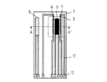
以下、本発明の実施の形態を図について説明する。図1は本発明の実施の形態1を示す上面図、図2は図1のA−A´線断面図である。ただし、図2の断面図は図1の上面図を多少拡大して示しており、これは、以降の同様のA−A´線断面図においても同じである。図において、1はシリコン基板、2はシリコン基板1を裏からエッチングして形成した空気スペース、3は空気スペース2上に設けられたダイヤフラム型薄肉部である。5は発熱部すなわち発熱抵抗体、6,7は発熱抵抗体5の上流側および下流側にそれぞれ配置された上流側および下流側温度検出部すなわち上流側および下流側感温抵抗体、8は上流側感温抵抗体6より上流側に配置され流体の温度を測定する流体温度検出部すなわち流体温度検出用感温抵抗体、9,10は絶縁層、11は発熱抵抗体5のごく近傍に配置された発熱抵抗体温度検出部、すなわち発熱抵抗体温度検出用感温抵抗体、12は発熱抵抗体5、上流側および下流側感温抵抗体6,7、流体温度検出用感温抵抗体8、並びに発熱抵抗体温度検出用感温抵抗体11の両端をそれぞれボンディングパッド13に接続する配線である。薄肉部3は絶縁層9,10、並びに絶縁層9,10に挟まれた発熱抵抗体5、及び感温抵抗体6,7,11から構成されている。
【0022】
発熱抵抗体5、感温抵抗体6,7、流体温度検出用感温抵抗体8は、スパッタ、あるいは蒸着などの成膜技術により薄膜形成した後、エッチングにより所望の抵抗値になるようにパターニングしている。抵抗材料としては、信頼性の高い白金などを使用することが望ましい。
【0023】
発熱抵抗体5は、流体温度検出用感温抵抗体8によって測定される空気の温度よりも常に一定温度だけ高くなるように定温度差駆動されている。図3は基本的な定温度差駆動回路の簡略回路図であり、発熱抵抗体5、流体温度検出用感温抵抗体8、及び固定抵抗14,15によりブリッジ回路を構成している。空気の流速の変動により発熱抵抗体5の温度が変化したり、空気の温度が変化して流体温度検出用感温抵抗体8の温度が変化したりして、ブリッジ回路のバランスが崩れると、差動増幅器16、及び、トランジスタ17が発熱抵抗体5に流れる加熱電流を制御し、元のバランス状態に戻すように働く。この結果、発熱抵抗体5と流体温度検出用感温抵抗体8との温度差が常に一定に保たれる。18は電源である。
【0024】
図4は基本的な温度差検出回路の簡略図であり、詳しくは、上流側感温抵抗体6と下流側感温抵抗体7の温度差を検出するための温度差検出回路の簡略図を示す。定電流源19により上流側感温抵抗体6(Ru)と下流側感温抵抗体7(Rd)に一定電流Isを流し、両者の両端電圧の差を取って、増幅回路部20により増幅し、出力端21から出力電圧Voutとして出力する。この場合の出力電圧Voutは以下の式で表される。
Vout=Vref+G・Rs0・αs・Is・(Td−Tu) …(1)
ここで、Rs0は上流側、および下流側感温抵抗体6,7の0℃の時の抵抗値、αsは上流側、及び下流側感温抵抗体6,7の抵抗温度係数である。また、Vref(38)は(Td−Tu)が負になった場合、つまり空気の流れが逆流の場合でも正の出力が得られるようにするために加えているバイアス電圧で定電圧源を用いている。上流側、および下流側感温抵抗体6,7を同じ材質で同じパターンに形成することにより、両者のRs0とαs はほぼ同一の値が得られる。また、Td,Tsはそれぞれ上流側、及び下流側感温抵抗体6,7の温度である。Gは増幅回路部により決定されるゲインであり、次式で表される。
G=1+(R2 /R1 ) …(2)
ただし、R2 /R1 =R4 /R3
また、上流側感温抵抗体6と下流側感温抵抗体7の温度差(Td−Tu)は近似的に以下のように表せる。
Td−Tu=AUnΔT …(3)
ここで、Uは空気の流速、△Tは図3の定温度差駆動回路により一定に保たれる空気と発熱抵抗体5との温度差、Aは係数である。式(1)と(3)を組み合わせると出力電圧Voutが流速Uに依存することが判る。
Vout=Vref+G・Rs0・αs・Is・AUn・ΔT …(4)
【0025】
前述したように、図3に示す定温度差駆動回路により、式(4)中の△Tは一定に保たれるはずである。しかし、実際には、発熱抵抗体5の発する熱が流体温度検出用感温抵抗体8にも伝わるため、流体温度検出用感温抵抗体8の温度は空気の温度よりも高くなっている。この流体温度検出用感温抵抗体8の温度上昇は空気の流速が小さいほど大きく、流速が速くなるにつれて流体温度検出用感温抵抗体8は冷却され、空気の温度に近づいていく。発熱抵抗体5の温度はこの流体温度検出用感温抵抗体8よりも一定温度高くなるように制御されるため、発熱抵抗体5の温度も空気の流速が大きくなるとともに低下することになる。従って、式(4)の△Tは実際は一定ではなく、流速が増すにつれて小さくなる。この△Tの負の流速依存性により、出力電圧Voutの流速依存性が抑えられ、感度や測定可能流速範囲が低下する。
【0026】
本実施の形態では、前述の△Tの流速による変動を、発熱抵抗体温度検出用感温抵抗体11により検出し、この発熱抵抗体温度検出用感温抵抗体11と上流側感温抵抗体6と下流側感温抵抗体7の3つの感温抵抗体の温度変化から出力電圧を導出するため、△Tの持つ負の流速依存性をキャンセルできる。
【0027】
図5は本発明の実施の形態1に係わる温度差検出用回路の簡略図である。この例ではまず、差動増幅器25により、下流側感温抵抗体7の温度に依存する電圧から発熱抵抗体温度検出用感温抵抗体11の温度に依存する電圧を引き算し、その後差動増幅器26によりさらに上流側感温抵抗体の温度に依存する電圧を引き算して出力電圧としている。こうすることにより、発熱抵抗体温度検出用感温抵抗体11の温度低下分が加味された出力電圧が発生するのでセンサの感度や測定可能流量範囲を向上できる。もちろん、図4に示すような増幅回路部を通した後の電圧を出力電圧としても良い。
【0028】
図5に示す3つの感温抵抗体6,7,11の+端側の電圧の流速による変化の様子を図6に示す。上流側感温抵抗体6の電圧27(Vu)と発熱抵抗体温度検出用感温抵抗体11の電圧29(Vsh)は流速が増すにつれて低下し、下流側感温抵抗体7の電圧28(Vd)は流速が増すにつれて上昇する。固定抵抗22,23,24を調節することにより、流速が零の時の3つの電圧を Vd=Vu+Vsh となるようにすることができる。図6においてVd―Vshを計算すると、流速が零の時にVuと一致し、傾きがVdよりも大きい曲線30が得られる。この曲線30からさらにVu曲線27を引き算すれば、単にVd−Vuを計算した曲線より傾きが大きい曲線が得られ、この電圧を出力とすることにより、センサの感度を向上させることが出来る。
【0029】
上記の効果は図5に示した回路だけではなく、図7および図8に示したような回路によっても実現することが出来る。図7はまず上流側感温抵抗体6の電圧27(Vu)と発熱抵抗体温度検出用感温抵抗体11の電圧(Vsh)を加算回路31により足し算し、その結果得られた電圧を下流側感温抵抗体7の電圧28(Vd)から引算して出力電圧を得る回路、図8はまず上流側感温抵抗体6の電圧27(Vu)から下流側感温抵抗体7の電圧28(Vd)を引き算し、その後、発熱抵抗体温度検出用感温抵抗体11の電圧(Vsh)を引き算して出力電圧を得る回路である。図5、図7、図8の回路を簡単に式で表すと以下のようになる。
図5:(Vd−Vsh)−Vu
図7:Vd−(Vu+Vsh)
図8:(Vd−Vu)−Vsh
【0030】
また、図9に示すような定電圧源32と定電流源19を併用した回路でも同様の効果を得ることが出来る。図9の回路において電圧Vdは下式で表される。
Vd=Rd・Vc/(Rd+Rsh)=1・Vc/{1+(Rsh/Rd)} …(5)
式(5)から判るようにRshが低下するとVdは大きくなる。このVdからVuを引き算すれば、発熱抵抗体温度検出用感温抵抗体11の温度低下分を加味した出力電圧Voutが得られる。
【0031】
さらに、図10に示すように、上流側感温抵抗体6と発熱抵抗体温度検出用感温抵抗体11を直列に接続して定電流を流し、その最上段の電圧Vuと下流側感温抵抗体7の電圧Vdとの差を取ることによっても、発熱抵抗体温度検出用感温抵抗体11の温度低下分を加味した出力電圧Voutが得られる。
【0032】
実施の形態2.
図11は本発明の実施の形態2を示す上面図、図12は図11のA−A´線断面図である。図において、シリコン基板1の薄肉部3に、発熱抵抗体5と発熱抵抗体5の上流側に感温抵抗体6,33a,33b、および下流側に感温抵抗体7がそれぞれ形成されている。2個の上流側感温抵抗体33a,33bは同じ材質で同じパーターンに形成されているため、同じ抵抗温度特性を持つ。また、同じ温度になるようにごく近接した位置に形成されている。
【0033】
この実施の形態においても、前述の実施の形態1と同様に、発熱抵抗体5、上流側感温抵抗体6、下流側感温抵抗体7、流体温度検出用感温抵抗体8を用いて温度差検出タイプの空気流速センサが構成される。このタイプのセンサの出力電圧Voutは前述した式(4)で表される。ここで増幅回路部のゲインGは図4の回路を用いると、前述した式2と同様に表される。
【0034】
図4のR1〜R4は全て固定抵抗を用いていたが、この実施形態では図13に示すように、R1に図11の感温抵抗体33aを使用し、R3には感温抵抗体33bを使用している。この感温抵抗体33aと33bの抵抗値をR33とおくと、増幅回路部のゲインGは次式のようになる。
G=1+R2/R33 …(6)
感温抵抗体33aと33bはともに発熱抵抗体5の上流側に位置しているため、流速が増大するとともにその温度は低下し、抵抗値も低下する。このため式(6)で表されるゲインGは逆に流速が増大するとともに大きくなる。よって式(4)で表される出力電圧Voutは、流速が増大すると、このゲインGの増大効果も含んだ形で大きくなり、ゲインGが固定されている場合に比べ、出力電圧Voutの流量依存性は大きくなり、センサの感度も向上し、測定可能流速範囲も拡大する。
【0035】
実施の形態3.
図14は本発明の実施の形態3に係わる定電流供給回路の簡略図である。図において、32は定電圧源、35,36は固定抵抗である。図4で示した回路では定電流源19を用いていたが、この図14に示す回路はこの定電流源19に代わって感度と測定範囲を改善する働きをする定電流回路である。図のように回路を構成すると、次式で表される定電流Isが端子AB間に流れる。
Is=Vi/R33=R36・Vc/{(R35+R36)・R33}=Vc/{1+(R35/R36)・R33}…(7)
式(7)のR33を固定すると一定電流Isを得ることが出来る。しかし、本実施形態3においては図13に示すように、このR33に上流側感温抵抗体33aを用いることを特徴とする。上流側感温抵抗体33aは空気の流速が増大すると冷却され、抵抗値が下がるため、式(7)で表される電流Isは逆に流速の増大とともに大きくなる。よって式(4)で表される出力電圧Voutは、流速が増大すると、この電流Isの増大効果も含んだ形で大きくなり、電流Isが固定されている場合に比べ、出力電圧Voutの流量依存性は大きくなり、センサの感度も向上し、測定可能流速範囲も拡大する。
【0036】
実施の形態4.
図15は本発明の実施の形態4に係わる定電流供給回路の簡略図である。この回路を用いると電流Isは次式のように表される。
Is=Vi/R35=R36・Vc/{(R33+R36)・R35}=Vc/{1+(R33/R36)・R35}…(8)
上流側感温抵抗体33aは空気の流速が増大すると冷却され、抵抗値(R33)が下がるため、式(8)で表される電流Isは逆に流速の増大とともに大きくなる。よって式(4)で表される出力電圧Voutは、流速が増大すると、この電流Isの増大効果も含んだ形で大きくなり、電流Isが固定されている場合に比べ、出力電圧Voutの流量依存性は大きくなり、センサの感度も向上し、測定可能流速範囲も拡大する。もちろん、2つの上流側感温抵抗体33a,33bを用いて実施の形態3と4を組み合わせ効果を倍増させても良い。
【0037】
実施の形態5.
図16は本発明の実施の形態5に係わるバイアス電圧供給回路の簡略図である。図において、32は定電圧源、37は固定抵抗である。図4で示した回路では、バイアス電圧Vref (38)に定電圧源を用いていたが、本実施形態4においては、図16に示すように定電圧源の電圧を分圧して出力する定電圧回路を用いてバイアス電圧Vref を印加している。しかも、R33に図11に示した上流側感温抵抗体33aを用いている。図16の回路における出力端Cの電圧(Vref)は次式で表される。
Vref=R37・Vc/(R37+R33)=1・Vc/{1+(R33/R37)} …(9)
【0038】
上流側感温抵抗体33aは空気の流速が増大すると冷却され、抵抗値(R33)が下がるため、式(8)で表される電圧Vref は逆に流速の増大とともに大きくなる。よって式(4)で表される出力電圧Voutは、流速が増大すると、このバイアス電圧Vref の増大効果も含んだ形で大きくなり、バイアス電圧Vref が固定されている場合に比べ、出力電圧Voutの流量依存性は大きくなり、センサの感度も向上し、測定可能流速範囲も拡大する。
【0039】
実施の形態6.
図17は本発明の実施の形態6を示す上面図、図18は図17のA−A´線断面図である。図において、シリコン基板1の薄肉部3に、発熱抵抗体5と発熱抵抗体5の上流側に感温抵抗体6,33a,33b、および下流側に感温抵抗体7,34a,34bがそれぞれ形成されている。4個の上流側感温抵抗体33a,33b、及び34a,34bは同じ材質で同じ形成方法により形成されている。また、上流側感温抵抗体33aと33b、及び、下流側感温抵抗体34aと34bはそれぞれ同じ温度になるようにごく近接した位置に形成されている。
【0040】
この実施の形態においても、前述の実施の形態2と同様に、発熱抵抗体5、上流側感温抵抗体6、下流側感温抵抗体7、流体温度検出用感温抵抗体8を用いて温度差検出タイプの空気流速センサが構成される。実施の形態2では、増幅回路部20のゲインGに上流側感温抵抗体33aによって流速依存性を持たせてセンサの感度を向上させており、ゲインGは式(6)でG=1+R2 /R33)として表された。
【0041】
しかし、上流側感温抵抗体33aの抵抗値R33は空気の温度や湿度など流速以外の空気の状態によっても変化する。このため、流速が一定でも空気の温度等が変化すればゲインGも変化することになり、空気の温度などが変化するような場合には正確な流速検知は出来ない。そこで、本実施の形態6では、図19に示す回路図のように、増幅回路部20の固定抵抗R2,R4の代わりに、下流側感温抵抗体34aと34bを用いる。このときゲインGは次式で表される。
G=1+R34a/R33a …(10)
【0042】
上流側感温抵抗体33aと33bは、流速が増大するとともにその温度は低下し、抵抗値も低下する。また、下流側感温抵抗体34aと34bは、流速が増大するとともにその温度は若干上昇し、抵抗値も上昇する。このため式(10)で表されるゲインGは流速が増大するとともに大きくなる。よって式(4)で表される出力電圧Voutは、流速が増大すると、このゲインGの増大効果も含んだ形で大きくなり、ゲインGが固定されている場合に比べ、出力電圧Voutの流量依存性は大きくなり、センサの感度も向上し、測定可能流速範囲も拡大する。
【0043】
さらに、流速以外の条件によりR33が変化した場合、同じ材質で同じ方法により形成されたR34も同様に変化するため、ゲインGは変化しない。例えば、空気の温度が上昇して上流側感温抵抗体33aと33bの抵抗値が10%増加したとすれば、下流側感温抵抗体34aと34bの抵抗値も10%増加するため、両者の変化はキャンセルされ、ゲインGは一定に保たれる。このように、本実施の形態6によれば、ゲインGを流速によってのみ変化させ、空気の温度などその他の因子には依存しないようにでき、空気の温度などが変化する場合にも使用できる。
【0044】
実施の形態7.
本実施の形態7に係わるセンサの上面図と断面図は実施の形態6で示した図17,図18と同じである。この実施の形態においても、前述の実施の形態4と同様に、発熱抵抗体5、上流側感温抵抗体6、下流側感温抵抗体7、流体温度検出用感温抵抗体8を用いて温度差検出タイプの空気流速センサが構成される。実施の形態4では、上流、及び下流側感温抵抗体6,7に流す電流値Isを上流側感温抵抗体33aを用いて変化させてセンサの感度を向上させており、この電流値Isは式(8)で表された。
【0045】
しかし、上流側感温抵抗体33aの抵抗値R33は空気の温度や湿度など流速以外の空気の状態によっても変化する。このため、流速が一定でも空気の温度等が変化すれば電流値Isも変化することになり、空気の温度などが変化するような場合には正確な流速検知は出来ない。そこで、本実施形態7では、図20に示す回路図のように、固定抵抗R36の代わりに、下流側感温抵抗体34aを用いる。このとき電流値Isは次式で表される。

上流側感温抵抗体33aは、流速が増大するとともにその温度は低下し、抵抗値R33aも低下する。また、下流側感温抵抗体34aは、流速が増大するとともにその温度は若干上昇し、抵抗値R34aも上昇する。このため式(11)で表される電流値Isは流速が増大するとともに大きくなる。よって式(4)で表される出力電圧Voutは、流速が増大すると、この電流値Isの増大効果も含んだ形で大きくなり、電流値Isが固定されている場合に比べ、出力電圧Voutの流量依存性は大きくなり、センサの感度も向上し、測定可能流速範囲も拡大する。
【0047】
さらに、流速以外の条件によりR33aが変化した場合、同じ材質で同じ方法により形成されたR34aも同様に変化するため、電流値Isは変化しない。例えば、空気の温度が上昇して上流側感温抵抗体33aの抵抗値が10%増加したとすれば、下流側感温抵抗体34aの抵抗値も10%増加するため、両者の変化はキャンセルされ、電流値Isは一定に保たれる。このように、本実施の形態7によれば、電流値Isを流速によってのみ変化させ、空気の温度などその他の因子には依存しないようにでき、空気の温度などが変化する場合にも使用できる。
【0048】
実施の形態8.
本実施の形態8に係わるセンサの上面図と断面図は実施の形態6で示した図17,図18と同じである。この実施の形態においても、前述の実施の形態5と同様に、発熱抵抗体5、上流側感温抵抗体6、下流側感温抵抗体7、流体温度検出用感温抵抗体8を用いて温度差検出タイプの空気流速センサが構成される。実施の形態5では、バイアス電圧Vrefを上流側感温抵抗体33aを用いて変化させてセンサの感度を向上させており、この場合のバイアス電圧Vrefは式(9)で表された。
【0049】
しかし、上流側感温抵抗体33aの抵抗値R33は空気の温度や湿度など流速以外の空気の状態によっても変化する。このため、流速が一定でも空気の温度等が変化すればバイアス電圧Vrefも変化することになり、空気の温度などが変化するような場合には正確な流速検知は出来ない。そこで、本実施形態8では、図21に示す回路図のように、固定抵抗R37の代わりに、下流側感温抵抗体34aを用いる。このときバイアス電圧Vrefは次式で表される。
Vref=R34a・Vc/(R34a+R33a)=1・Vc/{1+(R33a/R34a)} …(9)
【0050】
上流側感温抵抗体33aは、流速が増大するとともにその温度は低下し、抵抗値R33aも低下する。また、下流側感温抵抗体34aは、流速が増大するとともにその温度は若干上昇し、抵抗値R34aも上昇する。このため式(12)で表されるバイアス電圧Vrefは流速が増大するとともに大きくなる。よって式(4)で表される出力電圧Voutは、流速が増大すると、このバイアス電圧Vrefの増大効果も含んだ形で大きくなり、バイアス電圧Vrefが固定されている場合に比べ、出力電圧Voutの流量依存性は大きくなり、センサの感度も向上し、測定可能流速範囲も拡大する。
【0051】
さらに、流速以外の条件によりR33aが変化した場合、同じ材質で同じ方法により形成されたR34aも同様に変化するため、バイアス電圧Vrefは変化しない。例えば、空気の温度が上昇して上流側感温抵抗体33aの抵抗値が10%増加したとすれば、下流側感温抵抗体34aの抵抗値も10%増加するため、両者の変化はキャンセルされ、バイアス電圧Vrefは一定に保たれる。このように、本実施の形態8によれば、バイアス電圧Vrefを流速によってのみ変化させ、空気の温度などその他の因子には依存しないようにでき、空気の温度などが変化する場合にも使用できる。
【0052】
実施の形態9.
図22は本発明の実施の形態9を示す上面図、図23は図22のA−A´線断面図である。図において、シリコン基板1の薄肉部3に、発熱抵抗体5、その上流側に感温抵抗体6、および下流側に感温抵抗体7がそれぞれ形成されている。抵抗体5,6,7は薄肉部3の下流側に偏った位置に形成されているため、上流側感温抵抗体6から薄肉部3の上流側エッジ部までの距離は、下流側感温抵抗体7から薄肉部3の下流側エッジ部までの距離よりも大きくなっている。
【0053】
このように、抵抗体5,6,7を薄肉部3の下流側に偏った位置に形成することにより、上流側感温抵抗体6の流速増大による温度降下を大きくでき、また下流側感温抵抗体7の流速増大による温度上昇も大きくできる。
【0054】
このことを裏付ける実験結果を図24,25,26に示す。この実験は、図24に示すような薄肉部3の幅の異なる2種類の流速センサに実際に空気の流れを与え、上流側、及び、下流側感温抵抗体6,7の温度の流速による変化を調べたものである。その結果が図25と図26で、図25は2つのセンサの上流側感温抵抗体6の流速による温度変化を比較したグラフ、図26は2つのセンサの下流側感温抵抗体7の流速による温度変化を比較したグラフである。
【0055】
図25を見ると、薄肉部3の幅が大きい方が上流側感温抵抗体6の温度変化が大きいことが判る。つまり、上流側感温抵抗体6の温度変化を大きくするには薄肉部3の幅が大きい方が有利である。また、図26を見ると、薄肉部3の幅が小さい方が下流側感温抵抗体7の温度変化が大きいことが判る。つまり、下流側感温抵抗体7の温度変化を大きくするには薄肉部3の幅が小さい方が有利である。
【0056】
以上の実験結果から、図22のように薄肉部3の下流側に偏った位置に抵抗体5,6,7を形成することにより、上流側感温抵抗体6と下流側感温抵抗体7の温度変化を、抵抗体5,6,7が薄肉部の中央にあるときよりも大きくすることができ、両者の温度差もより大きな値が得られる。その結果、センサの感度を向上させ、測定可能流速範囲を拡大することが出来る。
【0057】
【発明の効果】
本発明の第1の構成である熱式流速センサによれば、薄肉部が形成された半導体基板と、この薄肉部に形成された発熱部と、同じく薄肉部に形成され、前記発熱部の上流側および下流側にそれぞれ配置された上流側および下流側温度検出部と、前記発熱部の極めて近傍に設けられた第3の温度検出部を備えるとともに、前記上流側温度検出部より上流側に流体温度検出部を備え、前記発熱部を前記流体温度検出部により検出された流体温度に対して定温度差駆動した時に前記上流側温度検出部、下流側温度検出部、および第3の温度検出部との間に生じる温度差から流速を検出するようにしたので、流体温度検出部の温度低下による発熱部の温度低下分が出力に加味され、センサの感度向上と測定可能流速範囲の拡大が実現できる。
【0058】
また、本発明の第2の構成である熱式流速センサによれば、薄肉部が形成された半導体基板と、この薄肉部に形成された発熱部と、同じく薄肉部に形成され、前記発熱部の上流側および下流側にそれぞれ配置された上流側および下流側温度検出部と、発熱部の上流側近傍に設けられた第4の温度検出部を備えるとともに、前記上流側温度検出部より上流側に流体温度検出部を備え、前記発熱部を前記流体温度検出部により検出された流体温度に対して定温度差駆動した時に生じる前記上流側温度検出部と下流側温度検出部との温度差から得られる信号により空気流速を検出する熱式流速センサにおいて、前記温度差信号に増幅を施す際に、その利得を前記第4の温度検出部の抵抗値によって変化させるようにしたので、利得の持つ流量依存性の分だけセンサの感度を向上させることができ、測定可能流速範囲も拡大できる。
【0059】
また、本発明の第3の構成である熱式流速センサによれば、薄肉部が形成された半導体基板と、この薄肉部に形成された発熱部と、同じく薄肉部に形成され、前記発熱部の上流側および下流側にそれぞれ配置された上流側および下流側温度検出部と、発熱部の上流側近傍に設けられた第4の温度検出部を備えるとともに、前記上流側温度検出部より上流側に流体温度検出部を備え、前記発熱部を前記流体温度検出部により検出された流体温度に対して定温度差駆動した時に生じる前記上流側温度検出部と下流側温度検出部との温度差から得られる信号により空気流速を検出する熱式流速センサにおいて、前記上流側、および下流側温度検出部の温度を検出するために流す電流値を前記第4の温度検出部の抵抗値によって変化させるようにしたので、電流の持つ流量依存性の分だけセンサの感度を向上させることができ、測定可能流速範囲も拡大できる。
【0060】
また、本発明の第4の構成である熱式流速センサによれば、薄肉部が形成された半導体基板と、この薄肉部に形成された発熱部と、同じく薄肉部に形成され、前記発熱部の上流側および下流側にそれぞれ配置された上流側および下流側温度検出部と、発熱部の上流側近傍に設けられた第4の温度検出部を備えるとともに、前記上流側温度検出部より上流側に流体温度検出部を備え、前記発熱部を前記流体温度検出部により検出された流体温度に対して定温度差駆動した時に生じる前記上流側温度検出部と下流側温度検出部との温度差から得られる信号により空気流速を検出する熱式流速センサにおいて、前記温度差信号に加えるバイアス信号を前記第4の温度検出部の抵抗値によって変化させるようにしたので、バイアス信号の持つ流量依存性の分だけセンサの感度を向上させることができ、測定可能流速範囲も拡大できる。
【0061】
また、本発明の第5の構成である熱式流速センサによれば、薄肉部が形成された半導体基板と、この薄肉部に形成された発熱部と、同じく薄肉部に形成され、前記発熱部の上流側および下流側にそれぞれ配置された上流側および下流側温度検出部と、発熱部の上流側および下流側にそれぞれ設けられた第4および第5の温度検出部を備えるとともに、前記上流側温度検出部より上流側に流体温度検出部を備え、前記発熱部を前記流体温度検出部により検出された流体温度に対して定温度差駆動した時に生じる前記上流側温度検出部と下流側温度検出部との温度差から得られる信号により空気流速を検出する熱式流速センサにおいて、前記第4,第5の温度検出部の抵抗値を用いて流速以外の原因による請求項2から4に記載の利得、電流、バイアス信号の変動を相殺するようにしたので、空気の流速以外の条件が変化する場合でも正確な流速検知ができる。
【0062】
また、本発明の第6の構成である熱式流速センサによれば、薄肉部が形成された半導体基板と、この薄肉部に形成された発熱部と、同じく薄肉部に形成され、前記発熱部の上流側および下流側にそれぞれ配置された上流側および下流側温度検出部を備えるとともに、前記上流側温度検出部より上流側に流体温度検出部を備え、前記発熱部を前記流体温度検出部により検出された流体温度に対して定温度差駆動した時に生じる前記上流側温度検出部と下流側温度検出部との温度差から得られる信号により空気流速を検出する熱式流速センサにおいて、前記発熱部と温度検出部を前記薄肉部上の空気の流れに対して下流側に偏った位置に配置するようにしたので、上流側温度検出部と下流側温度検出部の温度変化をより大きくすることができ、両者の温度差もより大きな値が得られ、センサの感度を向上させ、測定可能流速範囲を拡大することができる。
【図面の簡単な説明】
【図1】本発明の実施の形態1を示す上面図である。
【図2】図1のA−A′線断面図である。
【図3】基本的な定温度差駆動回路の簡略図である。
【図4】基本的な温度差検出回路の簡略図である。
【図5】本発明の実施の形態1に係わる温度差検出用回路の簡略図である。
【図6】本発明の実施の形態1に係わる流速による各抵抗の電圧変化を表したグラフである。
【図7】本発明の実施の形態1に係わる温度差検出用回路の簡略図である。
【図8】本発明の実施の形態1に係わる温度差検出用回路の簡略図である。
【図9】本発明の実施の形態1に係わる温度差検出用回路の簡略図である。
【図10】本発明の実施の形態1に係わる温度差検出用回路の簡略図である。
【図11】本発明の実施の形態2,3を示す上面図である。
【図12】図11のA−A′線断面図である。
【図13】本発明の実施の形態2に係わる温度差検出用回路の簡略図である。
【図14】本発明の実施の形態3に係わる定電流供給回路の簡略図である。
【図15】本発明の実施の形態4に係わる定電流供給回路の簡略図である。
【図16】本発明の実施の形態5に係わるバイアス電圧供給回路の簡略図である。
【図17】本発明の実施の形態6を示す上面図である。
【図18】図17のA−A′線断面図である。
【図19】本発明の実施の形態6に利用される温度差検出回路の簡略図である。
【図20】本発明の実施の形態7に係わる定電流供給回路の簡略図である。
【図21】本発明の実施の形態8に係わるバイアス電圧供給回路の簡略図である。
【図22】本発明の実施の形態9に係わる上面図である。
【図23】本発明の実施の形態9に係わる断面図である。
【図24】本発明の実施の形態9を裏付ける実験結果を示す図である。
【図25】本発明の実施の形態9を裏付ける実験結果を示す図である。
【図26】本発明の実施の形態9を裏付ける実験結果を示す図である。
【図27】従来例を示す断面図である。
【図28】図27の上面図である。
【図29】従来例に係わる感温抵抗体温度の流速依存性を示す図である。
【図30】従来例に係わる感温抵抗体の温度差の流速依存性を示す図である。
【図31】従来例に係わるヒーター温度制御回路図である。
【図32】従来例に係わる温度差検出回路図である。
【図33】従来例に係わる薄肉部の熱伝達模式図である。
【図34】別の従来例に係わる感温抵抗体温度の流速依存性である。
【符号の説明】
1 シリコン基板、2 空気スペース、3 薄肉部、5 発熱抵抗体、6 上流側感温抵抗体、7 下流側感温抵抗体、8 流体温度検出用感温抵抗体、11発熱抵抗体温度検出用感温抵抗体、33a,b 上流側感温抵抗体、34a,b 下流側感温抵抗体。[0001]
TECHNICAL FIELD OF THE INVENTION
The present invention relates to a flow rate sensor used in a place where a flow rate measurement of a fluid such as air is required, for example, an engine control of an automobile or an air conditioner, and more particularly to an improvement in detection sensitivity and an expansion of a measurable flow rate range.
[0002]
[Prior art]
FIG. 27 is a sectional view of a main part of a conventional thermal flow velocity sensor (conventional example 1) disclosed in Japanese Patent Publication No. 5-7659, for example, and FIG. 28 is a top view thereof. In the figure, 1 is a silicon substrate, 2 is an air space formed on the
[0003]
The basic operation of this conventional thermal flow sensor will be described. In FIG. 28, the
[0004]
When there is an air flow, the
[0005]
FIG. 31 and FIG. 32 show circuit examples for realizing these functions. The circuit shown in FIG. 31 is for controlling the temperature of the
[0006]
The temperature control circuit shown in FIG. 31 is configured by a Whiston bridge circuit 46 for keeping the temperature of the
[0007]
The circuit shown in FIG. 32 is for detecting a difference between the
[0008]
[Problems to be solved by the invention]
In order to make this type of thermal flow sensor have a wide range of measurable flow speeds and high sensitivity, it is desirable that the temperature of the
[0009]
FIG. 33 is a schematic diagram showing heat transfer in the
[0010]
Looking at the downstream
[0011]
As for the
[0012]
Further, F.I. According to a study by Mayer et al. (F. Mayer et al: Transducers @ 95 Eurosensors IX 132-C2 pp. 528-531), it is reported that the temperature of the downstream
[0013]
As described above, the conventional thermal flow rate sensor using the temperature difference has a problem that the sensitivity decreases as the flow rate increases, and the measurable flow rate range cannot be widened.
[0014]
The present invention has been made to solve the above-described problems, and has as its object to provide a thermal flow sensor capable of improving sensitivity and expanding a measurable flow speed range.
[0015]
[Means for Solving the Problems]
The thermal type flow sensor according to the first configuration of the present invention has a semiconductor substrate on which a thin portion is formed, a heat generating portion formed on the thin portion, and an upstream and downstream side of the heat generating portion which are also formed on the thin portion. And a third temperature detecting section provided very close to the heat generating section, and a fluid temperature detecting section located upstream of the upstream temperature detecting section. And when the heat generating unit is driven at a constant temperature difference with respect to the fluid temperature detected by the fluid temperature detecting unit, between the upstream temperature detecting unit, the downstream temperature detecting unit, and the third temperature detecting unit. The flow velocity is detected from the temperature difference generated at the time.
[0016]
The thermal type flow sensor according to the second configuration of the present invention has a semiconductor substrate on which a thin portion is formed, a heat generating portion formed on the thin portion, and an upstream and downstream side of the heat generating portion which are also formed on the thin portion. And a fourth temperature detection unit provided near the upstream side of the heating unit, and a fluid temperature detection unit located upstream of the upstream temperature detection unit. And air generated by a signal obtained from a temperature difference between the upstream temperature detection unit and the downstream temperature detection unit that is generated when the heating unit is driven at a constant temperature difference with respect to the fluid temperature detected by the fluid temperature detection unit. In the thermal type flow rate sensor for detecting a flow rate, when amplifying the temperature difference signal, the gain is changed by the resistance value of the fourth temperature detecting section.
[0017]
The thermal type flow sensor according to the third configuration of the present invention is a semiconductor substrate having a thin portion, a heat generating portion formed in the thin portion, and a heat generating portion formed in the same thin portion, and an upstream side and a downstream side of the heat generating portion. And a fourth temperature detection unit provided near the upstream side of the heating unit, and a fluid temperature detection unit located upstream of the upstream temperature detection unit. And air generated by a signal obtained from a temperature difference between the upstream temperature detection unit and the downstream temperature detection unit that is generated when the heating unit is driven at a constant temperature difference with respect to the fluid temperature detected by the fluid temperature detection unit. In the thermal type flow rate sensor for detecting a flow rate, the value of a current flowing for detecting the temperatures of the upstream and downstream temperature detecting sections is changed by the resistance value of the fourth temperature detecting section. .
[0018]
The thermal flow sensor according to the fourth configuration of the present invention is a semiconductor substrate having a thin portion, a heat generating portion formed in the thin portion, and a heat generating portion formed in the thin portion, and an upstream side and a downstream side of the heat generating portion. And a fourth temperature detection unit provided near the upstream side of the heating unit, and a fluid temperature detection unit located upstream of the upstream temperature detection unit. And air generated by a signal obtained from a temperature difference between the upstream temperature detection unit and the downstream temperature detection unit that is generated when the heating unit is driven at a constant temperature difference with respect to the fluid temperature detected by the fluid temperature detection unit. In a thermal type flow rate sensor for detecting a flow rate, a bias signal to be added to the temperature difference signal is changed by a resistance value of the fourth temperature detection section.
[0019]
A thermal flow sensor according to a fifth aspect of the present invention is a semiconductor substrate having a thin-walled portion, a heating portion formed in the thin-walled portion, and a heating portion formed in the thin-walled portion. And a fourth and a fifth temperature detector provided respectively on the upstream side and the downstream side of the heat generating part, and an upstream side and a downstream side of the upstream side temperature detector. A temperature difference between the upstream temperature detection unit and the downstream temperature detection unit that occurs when the heating unit is driven by a constant temperature difference with respect to the fluid temperature detected by the fluid temperature detection unit. 5. The gain, current, and bias according to
[0020]
A thermal flow sensor according to a sixth aspect of the present invention is a thermal flow sensor having a thin-walled portion, a heat-generating portion formed on the thin-walled portion, and a heat-generating portion formed on the thin-walled portion. And an upstream side and a downstream side temperature detecting unit disposed respectively on the sides, and a fluid temperature detecting unit provided upstream from the upstream side temperature detecting unit, and the heat generating unit detects the fluid temperature detected by the fluid temperature detecting unit. In a thermal type flow rate sensor that detects an air flow rate based on a signal obtained from a temperature difference between the upstream side temperature detection section and the downstream side temperature detection section that is generated when a constant temperature difference drive is performed, the heating section and the temperature detection section are It is arranged at a position deviated downstream with respect to the flow of air on the thin portion.
[0021]
BEST MODE FOR CARRYING OUT THE INVENTION
Hereinafter, embodiments of the present invention will be described with reference to the drawings. FIG. 1 is a top view showing the first embodiment of the present invention, and FIG. 2 is a sectional view taken along line AA ′ of FIG. However, the cross-sectional view of FIG. 2 is a slightly enlarged view of the top view of FIG. 1, and this is the same in the following similar cross-sectional views along the line AA ′. In the figure, 1 is a silicon substrate, 2 is an air space formed by etching the
[0022]
The
[0023]
The
[0024]
FIG. 4 is a simplified diagram of a basic temperature difference detection circuit. More specifically, FIG. 4 is a simplified diagram of a temperature difference detection circuit for detecting a temperature difference between the upstream
Vout = Vref + G · Rs0 · αs · Is · (Td−Tu) (1)
Here, Rs0 is the resistance value of the upstream and downstream temperature
G = 1 + (R2 / R1) (2)
Where R2 / R1 = R4 / R3
The temperature difference (Td-Tu) between the upstream
Td-Tu = AU n ΔT (3)
Here, U is the flow velocity of air, ΔT is the temperature difference between the air and the
Vout = Vref + G · Rs0 · αs · Is · AU n ・ ΔT (4)
[0025]
As described above, ΔT in equation (4) should be kept constant by the constant temperature difference drive circuit shown in FIG. However, in practice, the heat generated by the
[0026]
In the present embodiment, the above-described fluctuation due to the flow rate of ΔT is detected by the heating resistor temperature detecting
[0027]
FIG. 5 is a simplified diagram of a temperature difference detection circuit according to
[0028]
FIG. 6 shows how the voltages at the positive ends of the three temperature-
[0029]
The above effects can be realized not only by the circuit shown in FIG. 5 but also by the circuits shown in FIGS. FIG. 7 shows that the voltage 27 (Vu) of the upstream
Figure 5: (Vd-Vsh) -Vu
Figure 7: Vd- (Vu + Vsh)
Figure 8: (Vd-Vu) -Vsh
[0030]
The same effect can be obtained by a circuit using both the
Vd = Rd · Vc / (Rd + Rsh) = 1 · Vc / {1+ (Rsh / Rd)} (5)
As can be seen from equation (5), when Rsh decreases, Vd increases. By subtracting Vu from this Vd, an output voltage Vout that takes into account the temperature drop of the heating resistor temperature detecting temperature
[0031]
Further, as shown in FIG. 10, the upstream
[0032]
FIG. 11 is a top view showing the second embodiment of the present invention, and FIG. 12 is a sectional view taken along line AA ′ of FIG. In the figure, a
[0033]
Also in this embodiment, similarly to the first embodiment, the
[0034]
Although R1 to R4 in FIG. 4 all use fixed resistors, in this embodiment, as shown in FIG. 13, the temperature sensitive resistor 33a of FIG. 11 is used for R1, and the temperature
G = 1 + R2 / R33 (6)
Since the temperature-
[0035]
FIG. 14 is a simplified diagram of a constant current supply circuit according to
Is = Vi / R33 = R36.Vc / {(R35 + R36) .R33} = Vc / {1+ (R35 / R36) .R33} (7)
When R33 in the equation (7) is fixed, a constant current Is can be obtained. However, the third embodiment is characterized in that an upstream temperature-sensitive resistor 33a is used for this R33 as shown in FIG. The upstream temperature-sensitive resistor 33a is cooled when the flow velocity of the air increases, and the resistance value decreases. Therefore, the current Is expressed by the equation (7) increases with the flow velocity. Therefore, the output voltage Vout expressed by the equation (4) increases as the flow velocity increases, including the effect of increasing the current Is, and the output voltage Vout depends on the flow rate of the output voltage Vout as compared with the case where the current Is is fixed. Performance, sensor sensitivity is improved, and the measurable flow velocity range is expanded.
[0036]
Embodiment 4 FIG.
FIG. 15 is a simplified diagram of a constant current supply circuit according to Embodiment 4 of the present invention. Using this circuit, the current Is is represented by the following equation.
Is = Vi / R35 = R36.Vc / {(R33 + R36) .R35} = Vc / {1+ (R33 / R36) .R35} (8)
The upstream temperature-sensitive resistor 33a is cooled when the flow rate of the air increases, and the resistance value (R33) decreases. Therefore, the current Is represented by the equation (8) increases with the flow rate. Therefore, the output voltage Vout expressed by the equation (4) increases as the flow velocity increases, including the effect of increasing the current Is, and the output voltage Vout depends on the flow rate of the output voltage Vout as compared with the case where the current Is is fixed. Performance, sensor sensitivity is improved, and the measurable flow velocity range is expanded. Of course, the effects may be doubled by combining the third and fourth embodiments using two upstream temperature-
[0037]
FIG. 16 is a simplified diagram of a bias voltage supply circuit according to
Vref = R37 · Vc / (R37 + R33) = 1 · Vc / {1+ (R33 / R37)} (9)
[0038]
The upstream temperature-sensitive resistor 33a is cooled when the flow velocity of the air increases, and the resistance value (R33) decreases. Therefore, the voltage Vref expressed by the equation (8) increases with the increase of the flow velocity. Therefore, the output voltage Vout expressed by the equation (4) increases as the flow velocity increases, including the effect of increasing the bias voltage Vref, and the output voltage Vout of the output voltage Vout is smaller than when the bias voltage Vref is fixed. The flow rate dependency increases, the sensitivity of the sensor improves, and the measurable flow velocity range is expanded.
[0039]
FIG. 17 is a top view showing the sixth embodiment of the present invention, and FIG. 18 is a sectional view taken along line AA ′ of FIG. In the figure, a
[0040]
Also in this embodiment, similarly to the above-described second embodiment, the
[0041]
However, the resistance value R33 of the upstream temperature-sensitive resistor 33a also changes depending on the state of the air other than the flow speed, such as the temperature and humidity of the air. For this reason, even if the flow velocity is constant, if the temperature of the air changes, the gain G also changes. If the temperature of the air changes, the flow velocity cannot be accurately detected. Therefore, in the sixth embodiment, as shown in the circuit diagram of FIG. 19, the downstream temperature-
G = 1 + R34a / R33a (10)
[0042]
The temperature of the upstream temperature-
[0043]
Further, when R33 changes due to conditions other than the flow velocity, the gain G does not change because R34 formed of the same material by the same method also changes. For example, if the temperature of the air rises and the resistance values of the upstream
[0044]
The top view and the cross-sectional view of the sensor according to the seventh embodiment are the same as FIGS. 17 and 18 shown in the sixth embodiment. Also in this embodiment, similarly to the above-described fourth embodiment, the
[0045]
However, the resistance value R33 of the upstream temperature-sensitive resistor 33a also changes depending on the state of the air other than the flow velocity, such as the temperature and humidity of the air. For this reason, even if the flow velocity is constant, if the temperature of the air changes, the current value Is also changes. If the temperature of the air changes, the flow velocity cannot be accurately detected. Therefore, in the seventh embodiment, as shown in the circuit diagram of FIG. 20, the downstream temperature-
The temperature of the upstream temperature-sensitive resistor 33a decreases as the flow velocity increases, and the resistance value R33a also decreases. Further, the temperature of the downstream temperature-
[0047]
Further, when R33a changes due to conditions other than the flow velocity, R34a formed of the same material by the same method also changes, so that the current value Is does not change. For example, if the temperature of the air rises and the resistance value of the upstream temperature-sensitive resistor 33a increases by 10%, the resistance value of the downstream temperature-
[0048]
The top view and cross-sectional view of the sensor according to the eighth embodiment are the same as FIGS. 17 and 18 shown in the sixth embodiment. In this embodiment, similarly to the above-described fifth embodiment, the
[0049]
However, the resistance value R33 of the upstream temperature-sensitive resistor 33a also changes depending on the state of the air other than the flow velocity, such as the temperature and humidity of the air. For this reason, even if the flow velocity is constant, if the air temperature or the like changes, the bias voltage Vref also changes. If the air temperature or the like changes, accurate flow velocity detection cannot be performed. Therefore, in the eighth embodiment, as shown in the circuit diagram of FIG. 21, the downstream-side
Vref = R34a · Vc / (R34a + R33a) = 1 · Vc / {1+ (R33a / R34a)} (9)
[0050]
The temperature of the upstream temperature-sensitive resistor 33a decreases as the flow velocity increases, and the resistance value R33a also decreases. Further, the temperature of the downstream temperature-
[0051]
Further, when R33a changes due to conditions other than the flow velocity, the bias voltage Vref does not change because R34a formed of the same material and by the same method changes similarly. For example, if the temperature of the air rises and the resistance value of the upstream temperature-sensitive resistor 33a increases by 10%, the resistance value of the downstream temperature-
[0052]
FIG. 22 is a top view showing the ninth embodiment of the present invention, and FIG. 23 is a sectional view taken along line AA ′ of FIG. In the drawing, a
[0053]
As described above, by forming the
[0054]
Experimental results supporting this fact are shown in FIGS. In this experiment, the flow of air was actually given to two types of flow rate sensors having different widths of the
[0055]
25, it can be seen that the larger the width of the
[0056]
From the above experimental results, by forming the
[0057]
【The invention's effect】
According to the thermal type flow velocity sensor of the first configuration of the present invention, the semiconductor substrate having the thin portion, the heat generating portion formed in the thin portion, and the heat generating portion also formed in the thin portion, and the upstream of the heat generating portion An upstream side and a downstream side temperature detecting section disposed on the side and the downstream side, respectively, and a third temperature detecting section provided very close to the heat generating section, and a fluid is provided upstream of the upstream side temperature detecting section. A temperature detecting unit, wherein when the heating unit is driven at a constant temperature difference with respect to the fluid temperature detected by the fluid temperature detecting unit, the upstream temperature detecting unit, the downstream temperature detecting unit, and the third temperature detecting unit The flow rate is detected from the temperature difference that occurs between the sensor and the sensor, so the temperature drop of the heat generating part due to the temperature drop of the fluid temperature detector is added to the output, improving the sensor sensitivity and expanding the measurable flow rate range. it can.
[0058]
Further, according to the thermal type flow rate sensor of the second configuration of the present invention, the semiconductor substrate having the thin portion formed therein, the heat generating portion formed in the thin portion, and the heat generating portion formed in the thin portion also, Upstream and downstream temperature detectors respectively disposed on the upstream side and the downstream side, and a fourth temperature detector provided in the vicinity of the upstream side of the heat generating unit, and an upstream side from the upstream temperature detector. A fluid temperature detection unit, and the temperature difference between the upstream temperature detection unit and the downstream temperature detection unit that occurs when the heating unit is driven at a constant temperature difference with respect to the fluid temperature detected by the fluid temperature detection unit. In the thermal flow velocity sensor that detects the air flow velocity based on the obtained signal, when amplifying the temperature difference signal, the gain is changed by the resistance value of the fourth temperature detection unit. Flow rate dependence Min can be only improve the sensitivity of the sensor, the measurable flow rate range can be enlarged.
[0059]
Further, according to the thermal flow rate sensor having the third configuration of the present invention, the semiconductor substrate having the thin portion, the heat generating portion formed in the thin portion, and the heat generating portion also formed in the thin portion, Upstream and downstream temperature detectors respectively disposed on the upstream side and the downstream side, and a fourth temperature detector provided in the vicinity of the upstream side of the heat generating unit, and an upstream side from the upstream temperature detector. A fluid temperature detection unit, and the temperature difference between the upstream temperature detection unit and the downstream temperature detection unit that occurs when the heating unit is driven at a constant temperature difference with respect to the fluid temperature detected by the fluid temperature detection unit. In a thermal type flow velocity sensor that detects an air flow velocity based on an obtained signal, a current value flowing for detecting the temperatures of the upstream and downstream temperature detection sections is changed by a resistance value of the fourth temperature detection section. Made In, it is possible to improve the amount corresponding sensitivity of the sensor of the flow rate dependency with the current, the measurable flow rate range can be enlarged.
[0060]
Further, according to the thermal flow rate sensor having the fourth configuration of the present invention, the semiconductor substrate having the thin portion formed therein, the heat generating portion formed in the thin portion, and the heat generating portion also formed in the thin portion, Upstream and downstream temperature detectors respectively disposed on the upstream side and the downstream side, and a fourth temperature detector provided in the vicinity of the upstream side of the heat generating unit, and an upstream side from the upstream temperature detector. A fluid temperature detection unit, and the temperature difference between the upstream temperature detection unit and the downstream temperature detection unit that occurs when the heating unit is driven at a constant temperature difference with respect to the fluid temperature detected by the fluid temperature detection unit. In the thermal type flow velocity sensor that detects the air velocity based on the obtained signal, the bias signal to be added to the temperature difference signal is changed by the resistance value of the fourth temperature detection unit. Minute can be only improve the sensitivity of the sensor, the measurable flow rate range can be enlarged.
[0061]
Further, according to the thermal flow rate sensor having the fifth configuration of the present invention, the semiconductor substrate having the thin portion formed therein, the heat generating portion formed in the thin portion, and the heat generating portion also formed in the thin portion, Upstream and downstream temperature detectors respectively disposed on the upstream side and the downstream side, and fourth and fifth temperature detectors respectively provided on the upstream side and the downstream side of the heat generating unit. A fluid temperature detection unit provided upstream of the temperature detection unit, wherein the heating unit is driven by a constant temperature difference with respect to the fluid temperature detected by the fluid temperature detection unit, and the upstream temperature detection unit and the downstream temperature detection are generated. 5. A thermal flow sensor for detecting an air flow velocity based on a signal obtained from a temperature difference between the first and second temperature detectors, wherein the resistance value of the fourth and fifth temperature detectors is used to cause a cause other than the flow velocity. Gain, current, and Since so as to offset the variation of the astigmatism signal may correct the flow rate detection even when conditions other than the flow velocity of the air is changed.
[0062]
Further, according to the thermal flow rate sensor having the sixth configuration of the present invention, the semiconductor substrate having the thin portion, the heat generating portion formed in the thin portion, and the heat generating portion also formed in the thin portion, An upstream side and a downstream side temperature detector are respectively arranged on the upstream side and the downstream side, and a fluid temperature detector is provided on the upstream side of the upstream side temperature detector, and the heat generating part is provided by the fluid temperature detector. In the thermal type flow rate sensor for detecting an air flow rate by a signal obtained from a temperature difference between the upstream temperature detection section and the downstream temperature detection section which is generated when a constant temperature difference driving is performed with respect to the detected fluid temperature, the heat generation section And the temperature detector are arranged at a position deviated downstream with respect to the flow of air on the thin portion, so that the temperature change between the upstream temperature detector and the downstream temperature detector can be further increased. Yes, both Temperature difference also obtained a larger value, the sensitivity of the sensor is improved, it is possible to expand the measurable flow rate range.
[Brief description of the drawings]
FIG. 1 is a top view showing a first embodiment of the present invention.
FIG. 2 is a sectional view taken along line AA ′ of FIG.
FIG. 3 is a simplified diagram of a basic constant temperature difference drive circuit.
FIG. 4 is a simplified diagram of a basic temperature difference detection circuit.
FIG. 5 is a simplified diagram of a circuit for detecting a temperature difference according to the first embodiment of the present invention.
FIG. 6 is a graph showing a voltage change of each resistor according to a flow rate according to the first embodiment of the present invention.
FIG. 7 is a simplified diagram of a circuit for detecting a temperature difference according to the first embodiment of the present invention.
FIG. 8 is a simplified diagram of a circuit for detecting a temperature difference according to the first embodiment of the present invention.
FIG. 9 is a simplified diagram of a circuit for detecting a temperature difference according to the first embodiment of the present invention.
FIG. 10 is a simplified diagram of a circuit for detecting a temperature difference according to the first embodiment of the present invention.
FIG. 11 is a top
FIG. 12 is a sectional view taken along line AA ′ of FIG. 11;
FIG. 13 is a simplified diagram of a temperature difference detection circuit according to a second embodiment of the present invention.
FIG. 14 is a simplified diagram of a constant current supply circuit according to a third embodiment of the present invention.
FIG. 15 is a simplified diagram of a constant current supply circuit according to a fourth embodiment of the present invention.
FIG. 16 is a simplified diagram of a bias voltage supply circuit according to a fifth embodiment of the present invention.
FIG. 17 is a top view showing the sixth embodiment of the present invention.
18 is a sectional view taken along line AA 'of FIG.
FIG. 19 is a simplified diagram of a temperature difference detection circuit used in
FIG. 20 is a simplified diagram of a constant current supply circuit according to a seventh embodiment of the present invention.
FIG. 21 is a simplified diagram of a bias voltage supply circuit according to an eighth embodiment of the present invention.
FIG. 22 is a top view according to the ninth embodiment of the present invention.
FIG. 23 is a sectional view according to a ninth embodiment of the present invention.
FIG. 24 is a diagram showing experimental results supporting the ninth embodiment of the present invention.
FIG. 25 is a diagram showing experimental results supporting the ninth embodiment of the present invention.
FIG. 26 is a diagram showing experimental results supporting the ninth embodiment of the present invention.
FIG. 27 is a sectional view showing a conventional example.
FIG. 28 is a top view of FIG. 27.
FIG. 29 is a diagram showing the flow velocity dependence of the temperature of a temperature-sensitive resistor according to a conventional example.
FIG. 30 is a diagram showing the flow rate dependence of the temperature difference of the temperature-sensitive resistor according to the conventional example.
FIG. 31 is a heater temperature control circuit diagram according to a conventional example.
FIG. 32 is a circuit diagram of a temperature difference detection circuit according to a conventional example.
FIG. 33 is a schematic diagram of heat transfer of a thin portion according to a conventional example.
FIG. 34 is a flow rate dependence of the temperature of a temperature sensitive resistor according to another conventional example.
[Explanation of symbols]
Claims (6)
Priority Applications (1)
| Application Number | Priority Date | Filing Date | Title |
|---|---|---|---|
| JP21507697A JP3577902B2 (en) | 1997-08-08 | 1997-08-08 | Thermal flow sensor |
Applications Claiming Priority (1)
| Application Number | Priority Date | Filing Date | Title |
|---|---|---|---|
| JP21507697A JP3577902B2 (en) | 1997-08-08 | 1997-08-08 | Thermal flow sensor |
Publications (2)
| Publication Number | Publication Date |
|---|---|
| JPH1151954A JPH1151954A (en) | 1999-02-26 |
| JP3577902B2 true JP3577902B2 (en) | 2004-10-20 |
Family
ID=16666364
Family Applications (1)
| Application Number | Title | Priority Date | Filing Date |
|---|---|---|---|
| JP21507697A Expired - Lifetime JP3577902B2 (en) | 1997-08-08 | 1997-08-08 | Thermal flow sensor |
Country Status (1)
| Country | Link |
|---|---|
| JP (1) | JP3577902B2 (en) |
Families Citing this family (2)
| Publication number | Priority date | Publication date | Assignee | Title |
|---|---|---|---|---|
| DE10000496A1 (en) * | 2000-01-08 | 2001-07-12 | Bosch Gmbh Robert | Gas flow determination method and device |
| WO2003012376A1 (en) | 2000-05-15 | 2003-02-13 | Hitachi, Ltd. | Thermal air flow rate measuring apparatus and its flowmeter and internal combustion engine and thermal air flow rate measuring method using it |
-
1997
- 1997-08-08 JP JP21507697A patent/JP3577902B2/en not_active Expired - Lifetime
Also Published As
| Publication number | Publication date |
|---|---|
| JPH1151954A (en) | 1999-02-26 |
Similar Documents
| Publication | Publication Date | Title |
|---|---|---|
| US5753815A (en) | Thermo-sensitive flow sensor for measuring flow velocity and flow rate of a gas | |
| US7287424B2 (en) | Thermal type flow measurement apparatus having asymmetrical passage for flow rate measurement | |
| JP2704048B2 (en) | Current difference type thermal mass flow transducer | |
| JP4839395B2 (en) | Thermal flow meter | |
| JP4157034B2 (en) | Thermal flow meter | |
| JP4608843B2 (en) | Flow measuring device | |
| JPH10197309A (en) | Measuring element for thermal air flowmeter and thermal air flowmeter | |
| JPH0989619A (en) | Heat-sensitive flowmeter | |
| JP4470743B2 (en) | Flow sensor | |
| JP3802443B2 (en) | Flow rate sensor | |
| JP3969167B2 (en) | Fluid flow measuring device | |
| JP3293469B2 (en) | Thermal flow sensor | |
| JP3577902B2 (en) | Thermal flow sensor | |
| JP3454265B2 (en) | Thermal flow sensor | |
| JP5029509B2 (en) | Flow sensor | |
| JP2002005717A (en) | Thermal flow sensor | |
| JP5178261B2 (en) | Thermal flow meter | |
| JP3706283B2 (en) | Flow sensor circuit | |
| JPH0663800B2 (en) | Heater temperature control circuit | |
| JPH11351936A (en) | Thermal flow-rate sensor and thermal flow-rate detection circuit | |
| JP2000275075A (en) | Thermal flow sensor | |
| JPH09243423A (en) | Flow rate measuring apparatus | |
| JP4089657B2 (en) | Air flow sensor | |
| JPH10142249A (en) | Flow sensor | |
| JPH0943019A (en) | Thermal flow-rate measuring apparatus |
Legal Events
| Date | Code | Title | Description |
|---|---|---|---|
| A977 | Report on retrieval |
Free format text: JAPANESE INTERMEDIATE CODE: A971007 Effective date: 20040315 |
|
| A131 | Notification of reasons for refusal |
Free format text: JAPANESE INTERMEDIATE CODE: A131 Effective date: 20040330 |
|
| TRDD | Decision of grant or rejection written | ||
| A01 | Written decision to grant a patent or to grant a registration (utility model) |
Free format text: JAPANESE INTERMEDIATE CODE: A01 Effective date: 20040622 |
|
| A61 | First payment of annual fees (during grant procedure) |
Free format text: JAPANESE INTERMEDIATE CODE: A61 Effective date: 20040705 |
|
| FPAY | Renewal fee payment (event date is renewal date of database) |
Free format text: PAYMENT UNTIL: 20070723 Year of fee payment: 3 |
|
| FPAY | Renewal fee payment (event date is renewal date of database) |
Free format text: PAYMENT UNTIL: 20080723 Year of fee payment: 4 |
|
| FPAY | Renewal fee payment (event date is renewal date of database) |
Free format text: PAYMENT UNTIL: 20090723 Year of fee payment: 5 |
|
| FPAY | Renewal fee payment (event date is renewal date of database) |
Free format text: PAYMENT UNTIL: 20100723 Year of fee payment: 6 |
|
| FPAY | Renewal fee payment (event date is renewal date of database) |
Free format text: PAYMENT UNTIL: 20100723 Year of fee payment: 6 |
|
| FPAY | Renewal fee payment (event date is renewal date of database) |
Free format text: PAYMENT UNTIL: 20110723 Year of fee payment: 7 |
|
| FPAY | Renewal fee payment (event date is renewal date of database) |
Free format text: PAYMENT UNTIL: 20110723 Year of fee payment: 7 |
|
| FPAY | Renewal fee payment (event date is renewal date of database) |
Free format text: PAYMENT UNTIL: 20120723 Year of fee payment: 8 |
|
| FPAY | Renewal fee payment (event date is renewal date of database) |
Free format text: PAYMENT UNTIL: 20120723 Year of fee payment: 8 |
|
| FPAY | Renewal fee payment (event date is renewal date of database) |
Free format text: PAYMENT UNTIL: 20130723 Year of fee payment: 9 |
|
| R250 | Receipt of annual fees |
Free format text: JAPANESE INTERMEDIATE CODE: R250 |
|
| R250 | Receipt of annual fees |
Free format text: JAPANESE INTERMEDIATE CODE: R250 |
|
| R250 | Receipt of annual fees |
Free format text: JAPANESE INTERMEDIATE CODE: R250 |
|
| EXPY | Cancellation because of completion of term |