JP3555893B2 - Capture trap for concentratingly capturing pests, pest monitoring device equipped with the trap, and pest monitoring system - Google Patents
Capture trap for concentratingly capturing pests, pest monitoring device equipped with the trap, and pest monitoring system Download PDFInfo
- Publication number
- JP3555893B2 JP3555893B2 JP2002301668A JP2002301668A JP3555893B2 JP 3555893 B2 JP3555893 B2 JP 3555893B2 JP 2002301668 A JP2002301668 A JP 2002301668A JP 2002301668 A JP2002301668 A JP 2002301668A JP 3555893 B2 JP3555893 B2 JP 3555893B2
- Authority
- JP
- Japan
- Prior art keywords
- trap
- pest monitoring
- image
- photographing
- adhesive surface
- Prior art date
- Legal status (The legal status is an assumption and is not a legal conclusion. Google has not performed a legal analysis and makes no representation as to the accuracy of the status listed.)
- Expired - Fee Related
Links
Images

Description
【0001】
【発明の属する技術分野】
本発明は、昆虫類をはじめとする有害生物の工場など施設内への侵入を監視するための、有害生物を集中捕獲するための捕獲用トラップ、捕獲用トラップを備えた有害生物監視装置及び有害生物監視システムに関するものである。
【0002】
【従来の技術】
近年、消費者の商品に対する安全意識の高まりにより、主に食品等への異物混入に対するクレームが多数発生するようになっている。これらの異物混入の事例では、特に昆虫類が原因となるものが多くなっているため、工場など施設内における昆虫対策が重要な課題となっている。
【0003】
昆虫類の混入事故を防止するためには、昆虫類が侵入・発生しないための施設管理と、昆虫類を施設内で発見したときの殺虫剤散布等による防除作業が必要となる。これらの対策の前提として、多くの食品生産工場等の施設においては、昆虫類を捕獲する捕獲用トラップを用いて昆虫類の生息実態を検査し、その結果を分析して上記の対策を講じることが行われている。
【0004】
上記の捕獲用トラップは、昆虫類を効率的に捕獲するために、昆虫を捕える粘着面を備えた粘着トラップや、飛翔昆虫を誘引光源に誘き寄せて捕獲するライトトラップなどが用いられており、トラップの構造について捕獲効率を高めるための発明もなされている(例えば、特許文献1参照)。
【0005】
【特許文献1】
特開2001−321056号公報
【0006】
【発明が解決しようとする課題】
上記のようなトラップを用いて行なわれる昆虫類の生息実態の検査においては、月に1〜2回の頻度でトラップの状況を確認することが一般的である。このような方法では、実際に異物が混入してしまった後に対策を講ずることとなるので、既に手遅れとなっている場合も少なくない。異物混入を防止するためには検査の頻度を高めることが望ましいが、防虫対策を施した施設内では通常は稀にしか異常が検出されないため、例えば毎日検査を行なうことすると、多数のトラップを対象に担当者が連日の調査・回収作業を行うこととなり、コスト対効果の面で問題がある。
【0007】
このような事情から、低コストでリアルタイム性の高い検査を行うことが可能な監視システムが求められるが、監視の対象となる昆虫類は微小なものが多く、かつ粘着面にも広く散在しやすいものであるため、例えば監視カメラを用いて撮影することとしても少ない台数のカメラで精緻な撮影を行うことは容易でないという問題がある。
【0008】
本発明は、このような課題に対応して、昆虫類をはじめとする有害生物の工場など施設内への侵入をリアルタイムに監視することが可能な、有害生物を集中捕獲するための捕獲用トラップ、捕獲用トラップを備えた有害生物監視装置及び有害生物監視システムを提供することを目的とするものである。
【0009】
【課題を解決するための手段】
このような課題を解決するために、第一の発明は、有害生物を捕獲するための捕獲用トラップと、前記捕獲用トラップの少なくとも一部を撮影するトラップ撮影手段と、を備える有害生物監視装置であって、前記捕獲用トラップには、誘引光源の下に、底面退出口より広い上面侵入口を有する通過部が設けられ、前記底面退出口の下部には有害生物を捕獲するための粘着面が、水平面に対して傾斜して設けられており、前記トラップ撮影手段は、前記粘着面の少なくとも一部を撮影することを特徴とする有害生物監視装置である。前記粘着面は、水平面に対して45度以上の角度に傾斜して設けられていることを特徴とすることもできる。前記上面侵入口の直径に対する前記底面退出口の直径の比率は、100分の11以下であることを特徴とすることもできる。
【0010】
この発明は、粘着トラップなどの捕獲用トラップを用いて昆虫類などの有害生物を捕獲し、捕獲したトラップに監視カメラ等を併設して撮影の対象となる範囲を限定することにより、監視カメラによる撮影を可能にすることを特徴とする。通常の状態では飛翔などにより散在してカメラでは監視しにくい昆虫類などの有害生物を、トラップに対象を限定することで、効率的に撮影して監視することが可能になる。
【0011】
ここで有害生物としては、主として異物混入の対象となる昆虫類を対象とするが、施設内への侵入を防ぐ必要がある生物であれば、ネズミなどの動物類も含まれる。有害であることには、当該生物が毒性を有することだけではなく、人に不快感を与えるなど心理的に有害であることも含まれる。捕獲用トラップには、粘着トラップやライトトラップなど、有害生物を捕獲することが可能な全てのトラップが含まれる。
【0012】
第二の発明は、有害生物を捕獲するための捕獲用トラップと、前記捕獲用トラップの少なくとも一部を撮影するトラップ撮影手段と、前記トラップ撮影手段が撮影した画像を通信ネットワークで接続された前記画像の管理装置に送信する画像送信手段と、を備える有害生物監視システムであって、前記捕獲用トラップには、誘引光源の下に、底面退出口より広い上面侵入口を有する通過部が設けられ、前記底面退出口の下部には有害生物を捕獲するための粘着面が、水平面に対して傾斜して設けられており、前記トラップ撮影手段は、前記粘着面の少なくとも一部を撮影することを特徴とする有害生物監視システムである。
【0013】
この発明は、前記第一の発明の有害生物監視装置から撮影した画像について通信ネットワークを通じて管理者に送信できるよう構成することにより、管理者によるリアルタイムの監視を可能にする。管理装置は管理者が送信された画像を管理できる機器であればよく、管理専用のサーバであってもよいし、汎用的に用いられるパソコンを使用してもよい。通信ネットワークには、インターネットの他にイントラネット、専用線などのデータ通信が可能な全てのネットワークが含まれる。
【0015】
前記第一の発明及び前記第二の発明では、粘着トラップなどの捕獲用トラップを用いて昆虫類などの有害生物を捕獲して、カメラにより撮影して監視する対象を限定するが、より効果的かつ効率的に画像を撮影するためには、少しでも狭い表面積の上に有害生物を集中的に捕獲できることが好ましい。前記第一の発明及び前記第二の発明は、主として飛翔性の昆虫類を対象に、一般の粘着トラップでは粘着面に昆虫類が散在して撮影すべき領域が広がってしまう問題に対処するため、誘引光源に集まった昆虫類を粘着面に集中させて、集中させた粘着面のみを撮影することで効率化するよう構成したものである。
【0016】
微小な昆虫が誘引光源であるランプ付近に接近すると、ランプへの衝突、落下、再飛来を繰返すことを発見したため、ランプの下側に通過部を設け、上面の侵入口を底面の退出口より広く構成したところ、昆虫が途中で止まることなく退出口の下に設けられた従来のトラップより狭い面積の粘着面に集中的に捕獲することが可能になった。
【0018】
さらに、前記第二の発明では、前記トラップ撮影手段は、所定の間隔で前記粘着面の少なくとも一部を撮影し、前記画像送信手段は、前記トラップ撮影手段が所定の間隔で撮影した前記粘着面の画像を送信することを特徴とすることもできる。前記トラップ撮影手段は連続して前記捕獲用トラップを撮影し、前記画像送信手段は連続して撮影した画像の一部に変化が生じた場合に変化が生じた後の画像を送信することを特徴としてもよい。前記トラップ撮影手段は連続して前記捕獲用トラップを撮影し、前記画像送信手段は有害生物が付着した画像を選択して送信することを特徴としてもよい。
【0019】
上記の第一の方法においては、例えば1時間毎といった定期的な撮影のタイミングを設定して、画像を撮影・送信することにより、監視者やシステムに負担の少ない検査が可能になる。第二の方法においては、撮影した画像を直前に撮影した画像と対比することにより、変化した画像のみを送信するよう設定することで、無駄な画像の送受信を排除してハードウェアやネットワークにかかる負担を軽減することができる。第三の方法においては、有害生物が付着した画像のみを選択的に送信することにより、有害生物が発生していない状態の無駄な画像の送受信を排除して、同様にハードウェアやネットワークにかかる負担を軽減することができる。第二、第三の方法における連続した撮影とは、動画のように切れ目なく撮影を行ってもよいし、10分毎、1時間毎のように一定間隔をあけて断続的に撮影を行うものであってもよい。
【0020】
【発明の実施の形態】
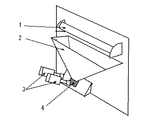
本発明の好ましい実施の形態について、図面を用いて以下に説明する。図1は、本発明にかかる有害生物を集中捕獲するための捕獲用トラップを備えた有害生物監視システムの構成の一例を示す図である。図2は、本発明にかかる有害生物を集中捕獲するための捕獲用トラップの正面図、側面図及び平面図である。図3は、本発明にかかる有害生物を集中捕獲するための捕獲用トラップの斜視図である。
【0021】
図1において、本発明にかかる有害生物監視システムは監視装置10であり、トラップ11、監視カメラ12、制御装置13、ルータ14、モデム15より構成されている。監視装置10は、インターネットを通じて管理用サーバ20と接続されており、監視カメラ12で撮影された画像データは、制御装置13が指定した送信先に対してルータ14を通じて、管理用サーバ20に送信される。管理用サーバ20には監視用端末30からインターネットを通じてアクセスし、画像データを参照することができる。
【0022】
また、監視装置10は、専用電話回線41を通じてモデム42を備えた監視用端末40と接続するよう構成してもよい。監視カメラ12で撮影された画像データは、制御装置13が指定した送信先に対してモデム15よりダイヤルアップで専用電話回線41に接続され、モデム42を介して監視用端末40に送信される。
【0023】
従来の検査方法では、トラップに設けた長大な粘着リボン、粘着紙又は粘着テープを月1回など定期的に回収し、昆虫等の数を人手で数える作業を行っていた。これに対して本発明は、トラップ11に監視カメラ12を併設して、トラップの粘着面などの有害生物が存在する部分を撮影することで、撮影された画像データを用いてリアルタイム監視や遠隔監視を可能としている。
【0024】
このように監視用端末30又は40で有害生物の侵入状況をリアルタイム監視することにより、異常が生じた場合には即座に通報して、対策を講じることが可能になる。また、遠隔監視を可能とすることによって、頻繁に以上が生じるわけではない有害生物侵入の監視を集中的に行なうことにより、監視要員の合理化を図ることもできる。
【0025】
ここで使用するトラップ11については、使用する監視カメラ12がなるべく少数で、かつ容易に撮影することができるように、撮影の対象となる範囲をなるべく狭くすることが好ましい。そのためには、図2及び図3に示したような、粘着面に集中捕獲が可能な捕獲用トラップを用いることが好ましい。
【0026】
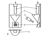
図2及び図3に示した捕獲用トラップは、誘引ランプ1、通過装置2及び粘着面4から構成される。図2のAは正面図、Bは側面図、Cは平面図である。粘着面4を撮影する監視カメラ3を設けると、監視用装置として利用することができる。
【0027】
本発明にかかる捕獲用トラップは、誘引ランプ1の下側に、広い上面部の侵入口と狭い底面部の退出口を有する通過装置2が設けられ、退出口の下側に昆虫を捕獲する粘着面3が設けられていることを特徴とするものであれば、材料や形態が限定されるものではない。通過装置は金属、プラスチック、紙などの材質が使用でき、水平断面が円形、半円形、四辺形又は三角形などとすること可能であり、上面部と底面部とが相違したり、ランプとの接続部分などが必要に応じて変形されたものであってもよいが、なるべく落下する昆虫が滑り落ちやすい材料や角度の形態であることが好ましい。
【0028】
微小な昆虫が誘引ランプ付近に接近すると、直接ランプに衝突する場合、また周囲を旋回してからランプに触れる場合も行動半径は限られたものであるため、その範囲で衝突、落下、再飛来を繰り返す。誘引ランプの下側に広い上面側の侵入口とこれより狭い底面側の退出口を備えた通過装置を設けると、昆虫は途中で止まることなく退出口の下側に備えられた、狭い面積の粘着面に集中的に捕獲される。
【0029】
ここで、粘着面4を監視カメラ3で撮影するよう構成すると、広範な範囲に監視カメラを設けることが必要なくなる。また、微小な昆虫を撮影する場合であっても、撮影対象となる部分を絞り込むことにより、撮影の精度を高めることができる。このように、本発明にかかる捕獲用トラップは昆虫類の撮影に適したものであり、この捕獲用トラップによって昆虫の侵入状況を確実かつ容易に監視することが可能になる。尚、粘着面4のサイズと数や監視カメラ3の性能と数を調整することにより、監視の精度を必要に応じて変更することもできる。
【0030】
撮影する画像は動画であっても静止画であってよいが、動画の場合には管理者が監視用カメラで常に監視を行わなければならないことと、データ容量が多くなるため通信ネットワークに負荷がかかるという問題がある。前者の監視負担については、管理用サーバ20や監視用端末30又は40の側で画像の変化を自動的にとらえるよう設定を行なってもよいが、動画用の全てのデータを送信することは無駄が多いため、監視装置10の画像送信側で、制御装置13において何らかの処理を行って送信する画像を制御することが望ましい。
【0031】
まず、有害生物の侵入は、通常の管理体制が施された施設内においては、左程頻繁におこるものではないため、例えば10分毎や1時間毎といった撮影間隔を設けて監視を行なうことも可能である。監視側では、設定された間隔で直前に受信した画像と比較して、異常が生じていないかを確認すればよい。
【0032】
次に、撮影側では継続的に、又は一定間隔をおいて断続的に撮影を行い、その中から画像の一部に変化が生じたもののみを選択して送信することもできる。このように設定すると、変化が生じた、つまり異常の生じた場合の画像のみを送信するため、画像送信によるシステムやネットワークにかかる負荷を軽減することができる。制御装置13は、新たに撮影した画像を直前に撮影した画像と対比し、変化が生じている場合のみ送信するよう設定される。
【0033】
さらに、撮影側では継続的に、又は一定間隔をおいて断続的に撮影を行い、その中から有害生物が付着したもののみを選択して送信することもできる。このように設定すると、有害生物の付着した問題の生じている場合の画像のみを送信するため、画像送信によるシステムやネットワークにかかる負荷を軽減することができる。制御装置13には、通常の状態における画像と有害生物の画像のパターンを記憶させておき、新たに撮影した画像が通常の状態と異なり、有害生物の画像を認識した場合のみ、その画像を送信するよう設定される。
【0034】
【実施例】
実施例1
縦型誘引ランプの下に、上面侵入口直径10cm、深さ14cm、底面退出口直径1.1cmの紙製コーンを取り付け、その1.5cm下に60度の角度で5cm四方の粘着面を設置した。この装置を夜間室内で窓に面して1時間点灯したところ、33匹の微小昆虫が粘着紙上の3cm四方内に捕獲され、モニターカメラでも容易に観察できた。
【0035】
実施例2
上面侵入口直径10cm、深さ11cm、底面退出口直径0.5cmの紙製コーンによっても、実施例1とほぼ同様の結果が得られた。
【0036】
実施例3
誘引ランプの下に,上面侵入口直径15cm、深さ9cm、底面退出口直径0.8cmのアルミ製のロートを取り付け、その下に45度傾斜の粘着面を設置したものを実施例1と同様に夜間室内で窓に面して1時間点灯したところ、21匹の微小昆虫が粘着紙上の3cm四方内に捕獲され、モニターカメラでも容易に観察できた。
【0037】
【発明の効果】
本発明にかかる監視装置及び監視システムにより、昆虫類をはじめとする有害生物の工場など施設内への侵入をリアルタイムに監視し、異常が発生した場合は即座に通報して対策を講じることが可能になる。
【0038】
また、本発明にかかる捕獲用トラップを用いることにより、少数の監視カメラを用いるだけで、有害生物の侵入を効率的に監視することができる。
【図面の簡単な説明】
【図1】本発明にかかる有害生物を集中捕獲するための捕獲用トラップを備えた有害生物監視システムの構成の一例を示す図である。
【図2】本発明にかかる有害生物を集中捕獲するための捕獲用トラップの正面図、側面図及び平面図である。
【図3】本発明にかかる有害生物を集中捕獲するための捕獲用トラップの斜視図である。
【符号の説明】
10 監視装置
11 トラップ
12 監視カメラ
13 制御装置
14 ルータ
15 モデム
20 管理用サーバ
30 監視用端末
40 監視用端末
41 専用電話回線
42 モデム
A 正面図
B 側面図
C 平面図
1 誘引ランプ
2 通過装置
3 監視カメラ
4 粘着面[0001]
TECHNICAL FIELD OF THE INVENTION
The present invention relates to a trap for collecting pests in a concentrated manner, a pest monitoring device provided with the trap, and a pest monitor for monitoring the invasion of pests such as insects into facilities such as factories. It relates to a biological monitoring system.
[0002]
[Prior art]
2. Description of the Related Art In recent years, as consumers have become more aware of the safety of commodities, a large number of complaints have been made mainly regarding foreign substances entering foods and the like. In these cases of foreign matter contamination, insects in particular are increasing in number, so that insect countermeasures in facilities such as factories have become an important issue.
[0003]
In order to prevent insects from being mixed, it is necessary to manage facilities to prevent insects from invading and generating, and to control insects by spraying insecticides when they are found in the facilities. As a premise of these measures, in many facilities such as food production factories, inspect the habitat of insects using traps for catching insects, analyze the results and take the above measures. Has been done.
[0004]
In order to efficiently capture insects, the trap for trapping includes an adhesive trap having an adhesive surface for catching insects, a light trap for attracting flying insects to an attracting light source and capturing them, and the like. An invention for improving the trapping efficiency of the trap structure has also been made (for example, see Patent Document 1).
[0005]
[Patent Document 1]
JP 2001-321056 A
[Problems to be solved by the invention]
In the inspection of the actual state of insects that are carried out using traps as described above, it is common to check the status of traps once or twice a month. In such a method, a countermeasure is taken after the foreign matter is actually mixed in, so that there are many cases where it is already too late. To prevent contamination, it is desirable to increase the frequency of inspections.However, abnormalities are usually rarely detected in facilities where insect repellent measures have been taken. In addition, the person in charge of conducting the survey and collection work every day has a problem in terms of cost effectiveness.
[0007]
Under such circumstances, a monitoring system capable of performing a low-cost, high-real-time inspection is required. However, the insects to be monitored are many small ones, and are easily scattered widely on the adhesive surface. Therefore, there is a problem that it is not easy to perform a precise photographing with a small number of cameras, for example, even when photographing using a surveillance camera.
[0008]
The present invention is directed to a trap for capturing pests in a concentrated manner, which can monitor intrusion of pests such as insects into a factory or the like in real time in response to such a problem. It is an object of the present invention to provide a pest monitoring device and a pest monitoring system including a trap for capturing.
[0009]
[Means for Solving the Problems]
In order to solve such a problem, a first invention is a pest monitoring device comprising: a trap for capturing pests; and a trap photographing means for photographing at least a part of the trap for trapping. In the trap for trapping, under the attraction light source, there is provided a passage portion having an upper surface entrance wider than the bottom exit, and an adhesive surface for trapping pests below the bottom exit. Is provided to be inclined with respect to a horizontal plane , and the trap photographing means photographs at least a part of the adhesive surface. The adhesive surface may be provided to be inclined at an angle of 45 degrees or more with respect to a horizontal plane . The ratio of the diameter of the bottom outlet to the diameter of the upper inlet may be 11/100 or less.
[0010]
The present invention captures pests such as insects using a trap for trapping such as an adhesive trap, and attaches a surveillance camera or the like to the captured trap to limit an area to be photographed. It is characterized in that photographing is enabled. In a normal state, pests such as insects scattered due to flight and are difficult to monitor with a camera can be efficiently photographed and monitored by limiting the target to traps.
[0011]
Here, the pests mainly target insects to be contaminated with foreign substances, but include animals such as rats as long as they need to prevent entry into the facility. Harmfulness includes not only toxicity of the organism but also psychological harm such as discomfort to humans. Capture traps include all traps capable of capturing pests, such as sticky traps and light traps.
[0012]
The second invention is characterized in that a trap for capturing pests, trap photographing means for photographing at least a part of the trap for trapping, and an image photographed by the trap photographing means are connected by a communication network. An image transmitting means for transmitting the image to the image management device, wherein the trap for trapping is provided with a passage section having an upper surface entrance wider than the bottom exit under the attraction light source. An adhesive surface for capturing pests is provided below the bottom outlet, and is inclined with respect to a horizontal plane , and the trap photographing unit photographs at least a part of the adhesive surface. It is a pest monitoring system characterized by:
[0013]
According to the present invention, an image captured by the pest monitoring device of the first invention can be transmitted to an administrator through a communication network, thereby enabling real-time monitoring by the administrator. The management device may be any device capable of managing the transmitted image by the administrator, and may be a dedicated server for management or a personal computer used for general purposes. The communication network includes all networks capable of data communication, such as an intranet and a dedicated line, in addition to the Internet.
[0015]
In the first invention and the second invention, a pest such as an insect is captured by using a trap for trapping such as an adhesive trap, and a target to be monitored by photographing with a camera is limited. In order to capture images efficiently and efficiently, it is preferable that pests can be intensively captured on even a small surface area. The first invention and the second invention are mainly intended for flying insects, and in general sticky traps, to cope with the problem that insects are scattered on the adhesive surface and the area to be photographed is widened. In this configuration, the insects gathered in the attracting light source are concentrated on the adhesive surface, and only the concentrated adhesive surface is photographed to increase the efficiency.
[0016]
When a small insect approached the lamp, which is the attracting light source, it was discovered that the lamp repeatedly collides with, fell, and re-joined the lamp. The wide configuration makes it possible for insects to be intensively caught on an adhesive surface having a smaller area than a conventional trap provided below an exit without stopping on the way.
[0018]
Further, in the second invention, the trap photographing unit photographs at least a part of the adhesive surface at a predetermined interval, and the image transmitting unit transmits the adhesive surface photographed at a predetermined interval by the trap photographing unit. images may also be characterized to transmit the. The trap photographing means continuously photographs the trap for capture, and the image transmitting means transmits an image after the change occurs when a part of the continuously photographed image changes. It may be. The trap photographing means may continuously photograph the trap for trapping, and the image transmitting means may select and transmit an image to which a pest is attached.
[0019]
In the first method described above, by setting the timing of regular photographing, for example, every one hour, and photographing and transmitting the image, it is possible to perform an inspection with less burden on a monitor or a system. In the second method, the photographed image is compared with the image photographed immediately before, so that only the changed image is set to be transmitted. The burden can be reduced. In the third method, by selectively transmitting only images to which pests are attached, unnecessary transmission and reception of images in which no pests are occurring are eliminated, and the same applies to hardware and networks. The burden can be reduced. The continuous shooting in the second and third methods refers to continuous shooting such as a moving image or intermittent shooting at regular intervals such as every 10 minutes and every hour. It may be.
[0020]
BEST MODE FOR CARRYING OUT THE INVENTION
Preferred embodiments of the present invention will be described below with reference to the drawings. FIG. 1 is a diagram showing an example of the configuration of a pest monitoring system including a trap for collecting pests in a concentrated manner according to the present invention. FIG. 2 is a front view, a side view, and a plan view of a trap for intensively capturing pests according to the present invention. FIG. 3 is a perspective view of a trap for intensively capturing pests according to the present invention.
[0021]
In FIG. 1, the pest monitoring system according to the present invention is a monitoring device 10 and includes a trap 11, a
[0022]
Further, the monitoring device 10 may be configured to be connected to a
[0023]
In the conventional inspection method, a long and long adhesive ribbon, adhesive paper or adhesive tape provided on the trap is periodically collected, such as once a month, and the number of insects or the like is manually counted. On the other hand, according to the present invention, a
[0024]
In this way, by monitoring the invading state of pests in real time by the monitoring
[0025]
Regarding the trap 11 used here, it is preferable that the range to be photographed is as narrow as possible so that the number of the
[0026]
The trap for capture shown in FIGS. 2 and 3 is composed of an
[0027]
The trap for trapping according to the present invention is provided with a pass-through
[0028]
When a small insect approaches the attracting lamp, the radius of action is limited when it directly collides with the lamp, or when it turns around and then touches the lamp. repeat. If a pass-through device with a wide upper entrance and a narrower exit at the bottom is provided below the induction lamp, insects will not stop halfway, Collected on the sticky surface.
[0029]
Here, if the surveillance camera 3 is configured to photograph the adhesive surface 4, it is not necessary to provide a surveillance camera in a wide range. Further, even in the case of photographing a small insect, the precision of the photographing can be improved by narrowing down the portion to be photographed. As described above, the trap for capturing according to the present invention is suitable for photographing insects, and the trap for trapping makes it possible to reliably and easily monitor the invasion state of insects. In addition, by adjusting the size and number of the adhesive surface 4 and the performance and number of the surveillance camera 3, the accuracy of monitoring can be changed as needed.
[0030]
The image to be captured may be a moving image or a still image, but in the case of a moving image, the administrator must constantly monitor with a surveillance camera. There is such a problem. Regarding the former monitoring burden, the
[0031]
First, pest invasion does not occur as frequently as in a facility with a normal management system, so monitoring may be performed at intervals of 10 minutes or 1 hour, for example. It is possible. The monitoring side may compare the image received immediately before at the set interval to check whether an abnormality has occurred.
[0032]
Next, the photographing side can photograph continuously or intermittently at regular intervals, and select and transmit only a part of the image in which a change has occurred. With this setting, only the image when a change has occurred, that is, when an abnormality has occurred is transmitted, so that the load on the system or network due to the image transmission can be reduced. The
[0033]
Further, the photographing side can perform photographing continuously or intermittently at regular intervals, and select and transmit only those to which pests have adhered. With this setting, only the image when the problem with the pests is attached is transmitted, so that the load on the system or the network due to the image transmission can be reduced. The
[0034]
【Example】
Example 1
A paper cone with a diameter of 10 cm at the top entrance, a depth of 14 cm and a diameter of 1.1 cm at the bottom exit is attached under the vertical invitation lamp, and an adhesive surface of 5 cm square is installed at an angle of 60 degrees 1.5 cm below it. did. When this device was turned on for 1 hour facing the window in the room at night, 33 small insects were captured within 3 cm squares on the adhesive paper and could be easily observed with a monitor camera.
[0035]
Example 2
Almost the same results as in Example 1 were obtained with a paper cone having a top inlet diameter of 10 cm, a depth of 11 cm, and a bottom outlet diameter of 0.5 cm.
[0036]
Example 3
An aluminum funnel with a top entrance diameter of 15 cm, a depth of 9 cm, and a bottom exit diameter of 0.8 cm was attached under the induction lamp, and a 45-degree inclined adhesive surface was installed underneath the same as in Example 1. When the room was turned on for 1 hour facing the window in the night room, 21 small insects were caught in a 3 cm square on the adhesive paper and could be easily observed with a monitor camera.
[0037]
【The invention's effect】
With the monitoring device and the monitoring system according to the present invention, it is possible to monitor intrusion of insects and other pests into a facility such as a factory in real time, and immediately report any abnormalities and take countermeasures. become.
[0038]
In addition, by using the trap for capture according to the present invention, the invasion of pests can be efficiently monitored using only a small number of surveillance cameras.
[Brief description of the drawings]
FIG. 1 is a diagram showing an example of a configuration of a pest monitoring system including a trap for collecting pests in a concentrated manner according to the present invention.
FIG. 2 is a front view, a side view, and a plan view of a trap for intensively capturing pests according to the present invention.
FIG. 3 is a perspective view of a trap for intensively capturing pests according to the present invention.
[Explanation of symbols]
DESCRIPTION OF SYMBOLS 10 Monitoring device 11
Claims (5)
前記捕獲用トラップの少なくとも一部を撮影するトラップ撮影手段と、
を備える有害生物監視装置であって、
前記捕獲用トラップには、誘引光源の下に、底面退出口より広い上面侵入口を有する通過部が設けられ、前記底面退出口の下部には有害生物を捕獲するための粘着面が、水平面に対して傾斜して設けられており、
前記トラップ撮影手段は、前記粘着面の少なくとも一部を撮影すること
を特徴とする有害生物監視装置。A trap for capturing pests,
Trap photographing means for photographing at least a part of the trap for capturing,
A pest monitoring device comprising:
The trap for trap is provided with a passage portion having an upper surface entrance wider than the bottom exit under the attracting light source, and an adhesive surface for catching pests is provided below the bottom exit on a horizontal surface . It is provided at an angle to the
The pest monitoring device, wherein the trap photographing unit photographs at least a part of the adhesive surface.
前記捕獲用トラップの少なくとも一部を撮影するトラップ撮影手段と、
前記トラップ撮影手段が撮影した画像を通信ネットワークで接続された前記画像の管理装置に送信する画像送信手段と、
を備える有害生物監視システムであって、
前記捕獲用トラップには、誘引光源の下に、底面退出口より広い上面侵入口を有する通過部が設けられ、前記底面退出口の下部には有害生物を捕獲するための粘着面が、水平面に対して傾斜して設けられており、
前記トラップ撮影手段は、前記粘着面の少なくとも一部を撮影すること
を特徴とする有害生物監視システム。A trap for capturing pests,
Trap photographing means for photographing at least a part of the trap for capturing,
Image transmitting means for transmitting the image photographed by the trap photographing means to the image management device connected via a communication network,
A pest monitoring system comprising:
The trap for trap is provided with a passage portion having an upper surface entrance wider than the bottom exit under the attracting light source, and an adhesive surface for catching pests is provided below the bottom exit on a horizontal surface . It is provided at an angle to the
The pest monitoring system, wherein the trap photographing unit photographs at least a part of the adhesive surface.
前記画像送信手段は、前記トラップ撮影手段が所定の間隔で撮影した前記粘着面の画像を送信すること
を特徴とする請求項2記載の有害生物監視システム。The trap photographing means photographs at least a part of the adhesive surface at a predetermined interval,
3. The pest monitoring system according to claim 2, wherein the image transmitting unit transmits an image of the adhesive surface photographed at a predetermined interval by the trap photographing unit.
Priority Applications (1)
| Application Number | Priority Date | Filing Date | Title |
|---|---|---|---|
| JP2002301668A JP3555893B2 (en) | 2002-10-16 | 2002-10-16 | Capture trap for concentratingly capturing pests, pest monitoring device equipped with the trap, and pest monitoring system |
Applications Claiming Priority (1)
| Application Number | Priority Date | Filing Date | Title |
|---|---|---|---|
| JP2002301668A JP3555893B2 (en) | 2002-10-16 | 2002-10-16 | Capture trap for concentratingly capturing pests, pest monitoring device equipped with the trap, and pest monitoring system |
Publications (2)
| Publication Number | Publication Date |
|---|---|
| JP2004135538A JP2004135538A (en) | 2004-05-13 |
| JP3555893B2 true JP3555893B2 (en) | 2004-08-18 |
Family
ID=32449956
Family Applications (1)
| Application Number | Title | Priority Date | Filing Date |
|---|---|---|---|
| JP2002301668A Expired - Fee Related JP3555893B2 (en) | 2002-10-16 | 2002-10-16 | Capture trap for concentratingly capturing pests, pest monitoring device equipped with the trap, and pest monitoring system |
Country Status (1)
| Country | Link |
|---|---|
| JP (1) | JP3555893B2 (en) |
Families Citing this family (7)
| Publication number | Priority date | Publication date | Assignee | Title |
|---|---|---|---|---|
| JP4953073B2 (en) * | 2007-04-12 | 2012-06-13 | 日本パルスモーター株式会社 | Insect trapping device |
| ITAR20110005A1 (en) * | 2011-02-28 | 2012-08-29 | Leonardo Spacone | MONITORING DEVICE FOR INSECTS, SMALL ANIMALS AND THE LIKE |
| CN106614440B (en) * | 2016-09-30 | 2022-10-25 | 桂林电子科技大学 | Intelligent crop pest forecasting system based on Internet of things |
| CN107094729A (en) * | 2017-05-22 | 2017-08-29 | 常州大学 | The machine visual detection device and method of counting of insect inside silo |
| AR113566A1 (en) * | 2017-11-07 | 2020-05-20 | Gerardo R Marchesini | INTEGRATED SYSTEM TO CONTROL, DETECT, MONITOR, EVALUATE AND TREAT CROP PESTS |
| CN112104845A (en) * | 2020-10-13 | 2020-12-18 | 广州韦斯浩环保科技有限公司 | Intelligent monitor of fly catching lamp platform |
| CN117099757B (en) * | 2023-08-25 | 2024-04-23 | 肇庆市承铭农业技术开发有限公司 | Method for monitoring solenopsis invicta by using solenopsis invicta prevention device |
Family Cites Families (3)
| Publication number | Priority date | Publication date | Assignee | Title |
|---|---|---|---|---|
| JP3435746B2 (en) * | 1993-09-20 | 2003-08-11 | 富士通株式会社 | Remote monitoring device |
| JP2001045945A (en) * | 1999-08-06 | 2001-02-20 | Terada Seisakusho Co Ltd | Device for investigating generation of pest |
| JP2001258454A (en) * | 2000-03-17 | 2001-09-25 | N Bii T Kk | Mothproofing tool comprising light source for suppressing behavior of insect |
-
2002
- 2002-10-16 JP JP2002301668A patent/JP3555893B2/en not_active Expired - Fee Related
Also Published As
| Publication number | Publication date |
|---|---|
| JP2004135538A (en) | 2004-05-13 |
Similar Documents
| Publication | Publication Date | Title |
|---|---|---|
| EP2632506B1 (en) | A real-time insect monitoring device | |
| CN111726986B (en) | System and method | |
| JP6949988B2 (en) | Domain identification method, device, storage medium and processor | |
| DE602004012409T2 (en) | PEST CONTROL SYSTEM | |
| CN109886999B (en) | Position determination method, device, storage medium and processor | |
| KR101980788B1 (en) | Trapping apparatus for pest monitoring and the method using the same | |
| KR101986222B1 (en) | Vermin Prevention System based on IoT Technology with Sound Detection | |
| EP3682737B1 (en) | System and method for counting agricultural pests inside a trap | |
| JP3555893B2 (en) | Capture trap for concentratingly capturing pests, pest monitoring device equipped with the trap, and pest monitoring system | |
| CN111165466A (en) | Method, device and system for repelling insects | |
| KR20200091524A (en) | Crop management system | |
| KR101471876B1 (en) | Control apparatus and method for trap | |
| CN112471103A (en) | Harmful organism comprehensive intelligent monitoring and preventing system | |
| JP7165354B2 (en) | Cloud-based harmful animal capture system | |
| CN217359877U (en) | Forest disease and pest monitoring and early warning system based on Internet of things | |
| KR100877552B1 (en) | Interactive system for automatic winding machine and operating method of the same | |
| KR101471873B1 (en) | Control managemement apparatus and method for trap | |
| Holguin et al. | Electronic traps for automated monitoring of insect populations | |
| KR101317910B1 (en) | Insect-pest prevention robot system by auto-attraction | |
| Potamitis et al. | Smart traps for automatic remote monitoring of Rhynchophorus ferrugineus (Coleoptera: Curculionidae) | |
| CN112806337A (en) | Target killing method, device, storage medium and electronic device | |
| WO2021029062A1 (en) | Catching device and server for catching device | |
| KR20030032838A (en) | A remote pest management system and a method thereof, and a real-time pest managing method | |
| Loughlin | Developments in the world of insect detection | |
| CN115413634B (en) | Deinsectization device for greenhouse |
Legal Events
| Date | Code | Title | Description |
|---|---|---|---|
| A131 | Notification of reasons for refusal |
Free format text: JAPANESE INTERMEDIATE CODE: A131 Effective date: 20040220 |
|
| A521 | Written amendment |
Free format text: JAPANESE INTERMEDIATE CODE: A523 Effective date: 20040223 |
|
| TRDD | Decision of grant or rejection written | ||
| A01 | Written decision to grant a patent or to grant a registration (utility model) |
Free format text: JAPANESE INTERMEDIATE CODE: A01 Effective date: 20040507 |
|
| A61 | First payment of annual fees (during grant procedure) |
Free format text: JAPANESE INTERMEDIATE CODE: A61 Effective date: 20040507 |
|
| R150 | Certificate of patent or registration of utility model |
Free format text: JAPANESE INTERMEDIATE CODE: R150 |
|
| R250 | Receipt of annual fees |
Free format text: JAPANESE INTERMEDIATE CODE: R250 |
|
| FPAY | Renewal fee payment (event date is renewal date of database) |
Free format text: PAYMENT UNTIL: 20130521 Year of fee payment: 9 |
|
| R250 | Receipt of annual fees |
Free format text: JAPANESE INTERMEDIATE CODE: R250 |
|
| LAPS | Cancellation because of no payment of annual fees |