JP3143605U - Surface decoration structure of articles - Google Patents
Surface decoration structure of articles Download PDFInfo
- Publication number
- JP3143605U JP3143605U JP2008002830U JP2008002830U JP3143605U JP 3143605 U JP3143605 U JP 3143605U JP 2008002830 U JP2008002830 U JP 2008002830U JP 2008002830 U JP2008002830 U JP 2008002830U JP 3143605 U JP3143605 U JP 3143605U
- Authority
- JP
- Japan
- Prior art keywords
- coating layer
- metal coating
- surface decoration
- base material
- decoration structure
- Prior art date
- Legal status (The legal status is an assumption and is not a legal conclusion. Google has not performed a legal analysis and makes no representation as to the accuracy of the status listed.)
- Ceased
Links
Images


Classifications
-
- C—CHEMISTRY; METALLURGY
- C23—COATING METALLIC MATERIAL; COATING MATERIAL WITH METALLIC MATERIAL; CHEMICAL SURFACE TREATMENT; DIFFUSION TREATMENT OF METALLIC MATERIAL; COATING BY VACUUM EVAPORATION, BY SPUTTERING, BY ION IMPLANTATION OR BY CHEMICAL VAPOUR DEPOSITION, IN GENERAL; INHIBITING CORROSION OF METALLIC MATERIAL OR INCRUSTATION IN GENERAL
- C23C—COATING METALLIC MATERIAL; COATING MATERIAL WITH METALLIC MATERIAL; SURFACE TREATMENT OF METALLIC MATERIAL BY DIFFUSION INTO THE SURFACE, BY CHEMICAL CONVERSION OR SUBSTITUTION; COATING BY VACUUM EVAPORATION, BY SPUTTERING, BY ION IMPLANTATION OR BY CHEMICAL VAPOUR DEPOSITION, IN GENERAL
- C23C14/00—Coating by vacuum evaporation, by sputtering or by ion implantation of the coating forming material
- C23C14/58—After-treatment
- C23C14/5873—Removal of material
-
- B—PERFORMING OPERATIONS; TRANSPORTING
- B05—SPRAYING OR ATOMISING IN GENERAL; APPLYING FLUENT MATERIALS TO SURFACES, IN GENERAL
- B05D—PROCESSES FOR APPLYING FLUENT MATERIALS TO SURFACES, IN GENERAL
- B05D5/00—Processes for applying liquids or other fluent materials to surfaces to obtain special surface effects, finishes or structures
- B05D5/06—Processes for applying liquids or other fluent materials to surfaces to obtain special surface effects, finishes or structures to obtain multicolour or other optical effects
- B05D5/067—Metallic effect
-
- B—PERFORMING OPERATIONS; TRANSPORTING
- B44—DECORATIVE ARTS
- B44C—PRODUCING DECORATIVE EFFECTS; MOSAICS; TARSIA WORK; PAPERHANGING
- B44C1/00—Processes, not specifically provided for elsewhere, for producing decorative surface effects
- B44C1/22—Removing surface-material, e.g. by engraving, by etching
- B44C1/228—Removing surface-material, e.g. by engraving, by etching by laser radiation
-
- C—CHEMISTRY; METALLURGY
- C23—COATING METALLIC MATERIAL; COATING MATERIAL WITH METALLIC MATERIAL; CHEMICAL SURFACE TREATMENT; DIFFUSION TREATMENT OF METALLIC MATERIAL; COATING BY VACUUM EVAPORATION, BY SPUTTERING, BY ION IMPLANTATION OR BY CHEMICAL VAPOUR DEPOSITION, IN GENERAL; INHIBITING CORROSION OF METALLIC MATERIAL OR INCRUSTATION IN GENERAL
- C23C—COATING METALLIC MATERIAL; COATING MATERIAL WITH METALLIC MATERIAL; SURFACE TREATMENT OF METALLIC MATERIAL BY DIFFUSION INTO THE SURFACE, BY CHEMICAL CONVERSION OR SUBSTITUTION; COATING BY VACUUM EVAPORATION, BY SPUTTERING, BY ION IMPLANTATION OR BY CHEMICAL VAPOUR DEPOSITION, IN GENERAL
- C23C14/00—Coating by vacuum evaporation, by sputtering or by ion implantation of the coating forming material
- C23C14/06—Coating by vacuum evaporation, by sputtering or by ion implantation of the coating forming material characterised by the coating material
- C23C14/14—Metallic material, boron or silicon
-
- C—CHEMISTRY; METALLURGY
- C23—COATING METALLIC MATERIAL; COATING MATERIAL WITH METALLIC MATERIAL; CHEMICAL SURFACE TREATMENT; DIFFUSION TREATMENT OF METALLIC MATERIAL; COATING BY VACUUM EVAPORATION, BY SPUTTERING, BY ION IMPLANTATION OR BY CHEMICAL VAPOUR DEPOSITION, IN GENERAL; INHIBITING CORROSION OF METALLIC MATERIAL OR INCRUSTATION IN GENERAL
- C23C—COATING METALLIC MATERIAL; COATING MATERIAL WITH METALLIC MATERIAL; SURFACE TREATMENT OF METALLIC MATERIAL BY DIFFUSION INTO THE SURFACE, BY CHEMICAL CONVERSION OR SUBSTITUTION; COATING BY VACUUM EVAPORATION, BY SPUTTERING, BY ION IMPLANTATION OR BY CHEMICAL VAPOUR DEPOSITION, IN GENERAL
- C23C18/00—Chemical coating by decomposition of either liquid compounds or solutions of the coating forming compounds, without leaving reaction products of surface material in the coating; Contact plating
- C23C18/16—Chemical coating by decomposition of either liquid compounds or solutions of the coating forming compounds, without leaving reaction products of surface material in the coating; Contact plating by reduction or substitution, e.g. electroless plating
- C23C18/1601—Process or apparatus
- C23C18/1603—Process or apparatus coating on selected surface areas
- C23C18/1605—Process or apparatus coating on selected surface areas by masking
-
- C—CHEMISTRY; METALLURGY
- C23—COATING METALLIC MATERIAL; COATING MATERIAL WITH METALLIC MATERIAL; CHEMICAL SURFACE TREATMENT; DIFFUSION TREATMENT OF METALLIC MATERIAL; COATING BY VACUUM EVAPORATION, BY SPUTTERING, BY ION IMPLANTATION OR BY CHEMICAL VAPOUR DEPOSITION, IN GENERAL; INHIBITING CORROSION OF METALLIC MATERIAL OR INCRUSTATION IN GENERAL
- C23C—COATING METALLIC MATERIAL; COATING MATERIAL WITH METALLIC MATERIAL; SURFACE TREATMENT OF METALLIC MATERIAL BY DIFFUSION INTO THE SURFACE, BY CHEMICAL CONVERSION OR SUBSTITUTION; COATING BY VACUUM EVAPORATION, BY SPUTTERING, BY ION IMPLANTATION OR BY CHEMICAL VAPOUR DEPOSITION, IN GENERAL
- C23C18/00—Chemical coating by decomposition of either liquid compounds or solutions of the coating forming compounds, without leaving reaction products of surface material in the coating; Contact plating
- C23C18/16—Chemical coating by decomposition of either liquid compounds or solutions of the coating forming compounds, without leaving reaction products of surface material in the coating; Contact plating by reduction or substitution, e.g. electroless plating
- C23C18/1601—Process or apparatus
- C23C18/1603—Process or apparatus coating on selected surface areas
- C23C18/1607—Process or apparatus coating on selected surface areas by direct patterning
- C23C18/161—Process or apparatus coating on selected surface areas by direct patterning from plating step, e.g. inkjet
-
- C—CHEMISTRY; METALLURGY
- C23—COATING METALLIC MATERIAL; COATING MATERIAL WITH METALLIC MATERIAL; CHEMICAL SURFACE TREATMENT; DIFFUSION TREATMENT OF METALLIC MATERIAL; COATING BY VACUUM EVAPORATION, BY SPUTTERING, BY ION IMPLANTATION OR BY CHEMICAL VAPOUR DEPOSITION, IN GENERAL; INHIBITING CORROSION OF METALLIC MATERIAL OR INCRUSTATION IN GENERAL
- C23C—COATING METALLIC MATERIAL; COATING MATERIAL WITH METALLIC MATERIAL; SURFACE TREATMENT OF METALLIC MATERIAL BY DIFFUSION INTO THE SURFACE, BY CHEMICAL CONVERSION OR SUBSTITUTION; COATING BY VACUUM EVAPORATION, BY SPUTTERING, BY ION IMPLANTATION OR BY CHEMICAL VAPOUR DEPOSITION, IN GENERAL
- C23C18/00—Chemical coating by decomposition of either liquid compounds or solutions of the coating forming compounds, without leaving reaction products of surface material in the coating; Contact plating
- C23C18/16—Chemical coating by decomposition of either liquid compounds or solutions of the coating forming compounds, without leaving reaction products of surface material in the coating; Contact plating by reduction or substitution, e.g. electroless plating
- C23C18/1601—Process or apparatus
- C23C18/1603—Process or apparatus coating on selected surface areas
- C23C18/1607—Process or apparatus coating on selected surface areas by direct patterning
- C23C18/1612—Process or apparatus coating on selected surface areas by direct patterning through irradiation means
-
- C—CHEMISTRY; METALLURGY
- C23—COATING METALLIC MATERIAL; COATING MATERIAL WITH METALLIC MATERIAL; CHEMICAL SURFACE TREATMENT; DIFFUSION TREATMENT OF METALLIC MATERIAL; COATING BY VACUUM EVAPORATION, BY SPUTTERING, BY ION IMPLANTATION OR BY CHEMICAL VAPOUR DEPOSITION, IN GENERAL; INHIBITING CORROSION OF METALLIC MATERIAL OR INCRUSTATION IN GENERAL
- C23C—COATING METALLIC MATERIAL; COATING MATERIAL WITH METALLIC MATERIAL; SURFACE TREATMENT OF METALLIC MATERIAL BY DIFFUSION INTO THE SURFACE, BY CHEMICAL CONVERSION OR SUBSTITUTION; COATING BY VACUUM EVAPORATION, BY SPUTTERING, BY ION IMPLANTATION OR BY CHEMICAL VAPOUR DEPOSITION, IN GENERAL
- C23C18/00—Chemical coating by decomposition of either liquid compounds or solutions of the coating forming compounds, without leaving reaction products of surface material in the coating; Contact plating
- C23C18/16—Chemical coating by decomposition of either liquid compounds or solutions of the coating forming compounds, without leaving reaction products of surface material in the coating; Contact plating by reduction or substitution, e.g. electroless plating
- C23C18/1601—Process or apparatus
- C23C18/1633—Process of electroless plating
- C23C18/1646—Characteristics of the product obtained
- C23C18/165—Multilayered product
-
- C—CHEMISTRY; METALLURGY
- C23—COATING METALLIC MATERIAL; COATING MATERIAL WITH METALLIC MATERIAL; CHEMICAL SURFACE TREATMENT; DIFFUSION TREATMENT OF METALLIC MATERIAL; COATING BY VACUUM EVAPORATION, BY SPUTTERING, BY ION IMPLANTATION OR BY CHEMICAL VAPOUR DEPOSITION, IN GENERAL; INHIBITING CORROSION OF METALLIC MATERIAL OR INCRUSTATION IN GENERAL
- C23C—COATING METALLIC MATERIAL; COATING MATERIAL WITH METALLIC MATERIAL; SURFACE TREATMENT OF METALLIC MATERIAL BY DIFFUSION INTO THE SURFACE, BY CHEMICAL CONVERSION OR SUBSTITUTION; COATING BY VACUUM EVAPORATION, BY SPUTTERING, BY ION IMPLANTATION OR BY CHEMICAL VAPOUR DEPOSITION, IN GENERAL
- C23C18/00—Chemical coating by decomposition of either liquid compounds or solutions of the coating forming compounds, without leaving reaction products of surface material in the coating; Contact plating
- C23C18/16—Chemical coating by decomposition of either liquid compounds or solutions of the coating forming compounds, without leaving reaction products of surface material in the coating; Contact plating by reduction or substitution, e.g. electroless plating
- C23C18/1601—Process or apparatus
- C23C18/1633—Process of electroless plating
- C23C18/1655—Process features
- C23C18/1664—Process features with additional means during the plating process
- C23C18/1667—Radiant energy, e.g. laser
-
- C—CHEMISTRY; METALLURGY
- C23—COATING METALLIC MATERIAL; COATING MATERIAL WITH METALLIC MATERIAL; CHEMICAL SURFACE TREATMENT; DIFFUSION TREATMENT OF METALLIC MATERIAL; COATING BY VACUUM EVAPORATION, BY SPUTTERING, BY ION IMPLANTATION OR BY CHEMICAL VAPOUR DEPOSITION, IN GENERAL; INHIBITING CORROSION OF METALLIC MATERIAL OR INCRUSTATION IN GENERAL
- C23C—COATING METALLIC MATERIAL; COATING MATERIAL WITH METALLIC MATERIAL; SURFACE TREATMENT OF METALLIC MATERIAL BY DIFFUSION INTO THE SURFACE, BY CHEMICAL CONVERSION OR SUBSTITUTION; COATING BY VACUUM EVAPORATION, BY SPUTTERING, BY ION IMPLANTATION OR BY CHEMICAL VAPOUR DEPOSITION, IN GENERAL
- C23C18/00—Chemical coating by decomposition of either liquid compounds or solutions of the coating forming compounds, without leaving reaction products of surface material in the coating; Contact plating
- C23C18/16—Chemical coating by decomposition of either liquid compounds or solutions of the coating forming compounds, without leaving reaction products of surface material in the coating; Contact plating by reduction or substitution, e.g. electroless plating
- C23C18/1601—Process or apparatus
- C23C18/1633—Process of electroless plating
- C23C18/1689—After-treatment
-
- C—CHEMISTRY; METALLURGY
- C23—COATING METALLIC MATERIAL; COATING MATERIAL WITH METALLIC MATERIAL; CHEMICAL SURFACE TREATMENT; DIFFUSION TREATMENT OF METALLIC MATERIAL; COATING BY VACUUM EVAPORATION, BY SPUTTERING, BY ION IMPLANTATION OR BY CHEMICAL VAPOUR DEPOSITION, IN GENERAL; INHIBITING CORROSION OF METALLIC MATERIAL OR INCRUSTATION IN GENERAL
- C23C—COATING METALLIC MATERIAL; COATING MATERIAL WITH METALLIC MATERIAL; SURFACE TREATMENT OF METALLIC MATERIAL BY DIFFUSION INTO THE SURFACE, BY CHEMICAL CONVERSION OR SUBSTITUTION; COATING BY VACUUM EVAPORATION, BY SPUTTERING, BY ION IMPLANTATION OR BY CHEMICAL VAPOUR DEPOSITION, IN GENERAL
- C23C18/00—Chemical coating by decomposition of either liquid compounds or solutions of the coating forming compounds, without leaving reaction products of surface material in the coating; Contact plating
- C23C18/16—Chemical coating by decomposition of either liquid compounds or solutions of the coating forming compounds, without leaving reaction products of surface material in the coating; Contact plating by reduction or substitution, e.g. electroless plating
- C23C18/31—Coating with metals
-
- C—CHEMISTRY; METALLURGY
- C23—COATING METALLIC MATERIAL; COATING MATERIAL WITH METALLIC MATERIAL; CHEMICAL SURFACE TREATMENT; DIFFUSION TREATMENT OF METALLIC MATERIAL; COATING BY VACUUM EVAPORATION, BY SPUTTERING, BY ION IMPLANTATION OR BY CHEMICAL VAPOUR DEPOSITION, IN GENERAL; INHIBITING CORROSION OF METALLIC MATERIAL OR INCRUSTATION IN GENERAL
- C23C—COATING METALLIC MATERIAL; COATING MATERIAL WITH METALLIC MATERIAL; SURFACE TREATMENT OF METALLIC MATERIAL BY DIFFUSION INTO THE SURFACE, BY CHEMICAL CONVERSION OR SUBSTITUTION; COATING BY VACUUM EVAPORATION, BY SPUTTERING, BY ION IMPLANTATION OR BY CHEMICAL VAPOUR DEPOSITION, IN GENERAL
- C23C18/00—Chemical coating by decomposition of either liquid compounds or solutions of the coating forming compounds, without leaving reaction products of surface material in the coating; Contact plating
- C23C18/54—Contact plating, i.e. electroless electrochemical plating
-
- C—CHEMISTRY; METALLURGY
- C23—COATING METALLIC MATERIAL; COATING MATERIAL WITH METALLIC MATERIAL; CHEMICAL SURFACE TREATMENT; DIFFUSION TREATMENT OF METALLIC MATERIAL; COATING BY VACUUM EVAPORATION, BY SPUTTERING, BY ION IMPLANTATION OR BY CHEMICAL VAPOUR DEPOSITION, IN GENERAL; INHIBITING CORROSION OF METALLIC MATERIAL OR INCRUSTATION IN GENERAL
- C23C—COATING METALLIC MATERIAL; COATING MATERIAL WITH METALLIC MATERIAL; SURFACE TREATMENT OF METALLIC MATERIAL BY DIFFUSION INTO THE SURFACE, BY CHEMICAL CONVERSION OR SUBSTITUTION; COATING BY VACUUM EVAPORATION, BY SPUTTERING, BY ION IMPLANTATION OR BY CHEMICAL VAPOUR DEPOSITION, IN GENERAL
- C23C2/00—Hot-dipping or immersion processes for applying the coating material in the molten state without affecting the shape; Apparatus therefor
- C23C2/26—After-treatment
-
- C—CHEMISTRY; METALLURGY
- C23—COATING METALLIC MATERIAL; COATING MATERIAL WITH METALLIC MATERIAL; CHEMICAL SURFACE TREATMENT; DIFFUSION TREATMENT OF METALLIC MATERIAL; COATING BY VACUUM EVAPORATION, BY SPUTTERING, BY ION IMPLANTATION OR BY CHEMICAL VAPOUR DEPOSITION, IN GENERAL; INHIBITING CORROSION OF METALLIC MATERIAL OR INCRUSTATION IN GENERAL
- C23C—COATING METALLIC MATERIAL; COATING MATERIAL WITH METALLIC MATERIAL; SURFACE TREATMENT OF METALLIC MATERIAL BY DIFFUSION INTO THE SURFACE, BY CHEMICAL CONVERSION OR SUBSTITUTION; COATING BY VACUUM EVAPORATION, BY SPUTTERING, BY ION IMPLANTATION OR BY CHEMICAL VAPOUR DEPOSITION, IN GENERAL
- C23C28/00—Coating for obtaining at least two superposed coatings either by methods not provided for in a single one of groups C23C2/00 - C23C26/00 or by combinations of methods provided for in subclasses C23C and C25C or C25D
-
- Y—GENERAL TAGGING OF NEW TECHNOLOGICAL DEVELOPMENTS; GENERAL TAGGING OF CROSS-SECTIONAL TECHNOLOGIES SPANNING OVER SEVERAL SECTIONS OF THE IPC; TECHNICAL SUBJECTS COVERED BY FORMER USPC CROSS-REFERENCE ART COLLECTIONS [XRACs] AND DIGESTS
- Y10—TECHNICAL SUBJECTS COVERED BY FORMER USPC
- Y10T—TECHNICAL SUBJECTS COVERED BY FORMER US CLASSIFICATION
- Y10T156/00—Adhesive bonding and miscellaneous chemical manufacture
- Y10T156/17—Surface bonding means and/or assemblymeans with work feeding or handling means
- Y10T156/1702—For plural parts or plural areas of single part
- Y10T156/1705—Lamina transferred to base from adhered flexible web or sheet type carrier
- Y10T156/1707—Discrete spaced laminae on adhered carrier
-
- Y—GENERAL TAGGING OF NEW TECHNOLOGICAL DEVELOPMENTS; GENERAL TAGGING OF CROSS-SECTIONAL TECHNOLOGIES SPANNING OVER SEVERAL SECTIONS OF THE IPC; TECHNICAL SUBJECTS COVERED BY FORMER USPC CROSS-REFERENCE ART COLLECTIONS [XRACs] AND DIGESTS
- Y10—TECHNICAL SUBJECTS COVERED BY FORMER USPC
- Y10T—TECHNICAL SUBJECTS COVERED BY FORMER US CLASSIFICATION
- Y10T428/00—Stock material or miscellaneous articles
- Y10T428/12—All metal or with adjacent metals
- Y10T428/12493—Composite; i.e., plural, adjacent, spatially distinct metal components [e.g., layers, joint, etc.]
- Y10T428/12535—Composite; i.e., plural, adjacent, spatially distinct metal components [e.g., layers, joint, etc.] with additional, spatially distinct nonmetal component
- Y10T428/12556—Organic component
- Y10T428/12569—Synthetic resin
-
- Y—GENERAL TAGGING OF NEW TECHNOLOGICAL DEVELOPMENTS; GENERAL TAGGING OF CROSS-SECTIONAL TECHNOLOGIES SPANNING OVER SEVERAL SECTIONS OF THE IPC; TECHNICAL SUBJECTS COVERED BY FORMER USPC CROSS-REFERENCE ART COLLECTIONS [XRACs] AND DIGESTS
- Y10—TECHNICAL SUBJECTS COVERED BY FORMER USPC
- Y10T—TECHNICAL SUBJECTS COVERED BY FORMER US CLASSIFICATION
- Y10T428/00—Stock material or miscellaneous articles
- Y10T428/24—Structurally defined web or sheet [e.g., overall dimension, etc.]
- Y10T428/24802—Discontinuous or differential coating, impregnation or bond [e.g., artwork, printing, retouched photograph, etc.]
- Y10T428/24835—Discontinuous or differential coating, impregnation or bond [e.g., artwork, printing, retouched photograph, etc.] including developable image or soluble portion in coating or impregnation [e.g., safety paper, etc.]
-
- Y—GENERAL TAGGING OF NEW TECHNOLOGICAL DEVELOPMENTS; GENERAL TAGGING OF CROSS-SECTIONAL TECHNOLOGIES SPANNING OVER SEVERAL SECTIONS OF THE IPC; TECHNICAL SUBJECTS COVERED BY FORMER USPC CROSS-REFERENCE ART COLLECTIONS [XRACs] AND DIGESTS
- Y10—TECHNICAL SUBJECTS COVERED BY FORMER USPC
- Y10T—TECHNICAL SUBJECTS COVERED BY FORMER US CLASSIFICATION
- Y10T428/00—Stock material or miscellaneous articles
- Y10T428/24—Structurally defined web or sheet [e.g., overall dimension, etc.]
- Y10T428/24802—Discontinuous or differential coating, impregnation or bond [e.g., artwork, printing, retouched photograph, etc.]
- Y10T428/24917—Discontinuous or differential coating, impregnation or bond [e.g., artwork, printing, retouched photograph, etc.] including metal layer
Landscapes
- Chemical & Material Sciences (AREA)
- Chemical Kinetics & Catalysis (AREA)
- Engineering & Computer Science (AREA)
- Materials Engineering (AREA)
- Mechanical Engineering (AREA)
- Metallurgy (AREA)
- Organic Chemistry (AREA)
- General Chemical & Material Sciences (AREA)
- Health & Medical Sciences (AREA)
- Toxicology (AREA)
- Physics & Mathematics (AREA)
- Optics & Photonics (AREA)
- Electrochemistry (AREA)
- General Health & Medical Sciences (AREA)
- Laminated Bodies (AREA)
- Physical Vapour Deposition (AREA)
- Eyeglasses (AREA)
- Other Surface Treatments For Metallic Materials (AREA)
Abstract
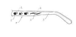
【課題】加工が容易であって、任意デザインの金属光沢による高級感のある装飾模様を形成することができ、要に臨んで、立体的な装飾模様を形成することも可能な物品の表面装飾構造を提供する。
【解決手段】基材1の表面において、少なくとも金属光沢を有する金属材料が層着した金属被膜層2を形成する一方、この金属被膜層2の少なくとも一部には剥離部21を設け、この剥離部21において前記基材1の表面が露出して、当該基材1の外観と残存した金属被膜層2の金属光沢との相異により装飾模様を形成し、基材1および金属被膜層2がそれぞれ表出した状態で、これらの表面が透光性を有する合成樹脂材料からなるクリアコーティング層3によって被覆して、前記金属光沢による装飾模様の表面を保護する。
【選択図】図1A surface decoration of an article which can be easily processed, can form a high-grade decorative pattern with a metallic luster of an arbitrary design, and can form a three-dimensional decorative pattern when necessary. Provide structure.
On the surface of a base material, a metal coating layer is formed on which at least a metallic material having a metallic luster is deposited, and at least a part of the metal coating layer is provided with a peeling portion. The surface of the base material 1 is exposed in the portion 21, and a decorative pattern is formed by the difference between the appearance of the base material 1 and the metallic luster of the remaining metal coating layer 2. In the state where they are exposed, these surfaces are covered with a clear coating layer 3 made of a synthetic resin material having translucency to protect the surface of the decorative pattern with metallic luster.
[Selection] Figure 1
Description
本考案は、物品装飾の改良、更に詳しくは、加工が容易であって、任意デザインの金属光沢による高級感のある装飾模様を形成することができ、要に臨んで、立体的な装飾模様を形成することも可能な物品の表面装飾構造に関するものである。 The present invention is an improvement of the decoration of the article, more specifically, it is easy to process and can form a high-grade decorative pattern with a metallic luster of any design. The present invention relates to a surface decoration structure of an article that can be formed.
周知のとおり、眼鏡フレームや時計、アクセサリーなどの宝飾品や携帯電話などは、その物品自体の形状に意匠性が求められているほか、その表面の色彩や図柄、質感などもデザインを構成する重要な要素である。 As is well known, jewelry frames such as eyeglass frames, watches, accessories, and mobile phones are required to have a design for the shape of the article itself, and the color, design, texture, etc. of the surface are also important for the design. Element.
従来、物品を装飾するものとしては、例えば、物品基材の表面全体に一様な金属メッキ加工を施したものが知られている(例えば、特許文献1参照)。 2. Description of the Related Art Conventionally, as an item for decorating an article, for example, an article obtained by performing uniform metal plating on the entire surface of an article substrate is known (for example, see Patent Document 1).
しかしながら、このような表面装飾にあっては、単に物品基材全体に一様な金属光沢が付与されただけのものであったため、物品基材自体の形状は変化しないで単に表面の質感が変更されるに過ぎない。 However, in such a surface decoration, since the uniform metallic luster was simply given to the entire article base material, the shape of the article base material itself did not change and the surface texture was simply changed. It is only done.
したがって、このような装飾効果は単調で質感以上の装飾性が表現されていないため意外性がなく、物品基材自体の形状による美感を凌駕することができないとともに、折角の金属光沢による高級感が、カバーリング手法の単調さゆえに相殺されて没却されてしまうおそれもあった。
本考案は、従来の物品装飾に上記のような不満があったことに鑑みて為されたものであり、その目的とするところは、加工が容易であって、任意デザインの金属光沢による高級感のある装飾模様を形成することができ、要に臨んで、立体的な装飾模様を形成することも可能な物品の表面装飾構造を提供することにある。 The present invention has been made in view of the above-mentioned dissatisfaction with conventional article decorations, and the object of the present invention is to provide an easy-to-process and high-class feeling due to metallic luster of any design. It is an object of the present invention to provide a surface decoration structure for an article that can form a decorative pattern having a certain shape and can form a three-dimensional decorative pattern.
本考案者が上記課題を解決するために採用した手段を添付図面を参照して説明すれば次のとおりである。 Means adopted by the present inventors for solving the above-described problems will be described with reference to the accompanying drawings.
即ち、本考案は、基材1の表面において、少なくとも金属光沢を有する金属材料が層着した金属被膜層2を形成する一方、
この金属被膜層2の少なくとも一部には剥離部21を設け、この剥離部21において前記基材1の表面が露出して、当該基材1の外観と残存した金属被膜層2の金属光沢との相異により装飾模様Pを形成し、
基材1および金属被膜層2がそれぞれ表出した状態で、これらの表面が透光性を有する合成樹脂材料からなるクリアコーティング層3によって被覆して、前記金属光沢による装飾模様Pの表面を保護するという技術的手段を採用したことによって、物品の表面装飾構造を完成させた。
That is, the present invention forms the
A
With the
また、本考案は、上記課題を解決するために、必要に応じて上記手段に加え、金属被膜層2における剥離部21を、レーザー光を照射することにより設けるという技術的手段を採用した。
Moreover, in order to solve the said subject, this invention employ | adopted the technical means of providing the
更にまた、本考案は、上記課題を解決するために、必要に応じて上記手段に加え、基材1を透光性を有する透明または半透明のプラスチック材料にして、照射したレーザー光を基材1を透過せしめて、当該基材1の対向側表面にも対称形状の剥離部21を設けて、装飾模様Pを形成するという技術的手段を採用した。
Furthermore, in order to solve the above-mentioned problems, the present invention makes the base material 1 a transparent or translucent plastic material having translucency in addition to the above means as necessary, and the irradiated laser light is the base material. 1 was used, and the technical means of forming the decorative pattern P by providing a
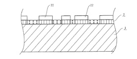
更にまた、本考案は、上記課題を解決するために、必要に応じて上記手段に加え、金属被膜層2における剥離部21を、金属被膜層2の表面の少なくとも一部にマスキング剤22を付着してマスキング部を形成する一方、非マスキング部における金属被膜層2を剥離することにより設けるという技術的手段を採用した。
Furthermore, in order to solve the above-mentioned problems, the present invention attaches a
更にまた、本考案は、上記課題を解決するために、必要に応じて上記手段に加え、金属被膜層2における剥離部21を設けるときに、パッド印刷、シルクスクリーン印刷、オフセット印刷、凸版印刷あるいは凹版印刷によりマスキング剤22を塗布するという技術的手段を採用した。
Furthermore, in order to solve the above-described problems, the present invention provides pad printing, silk screen printing, offset printing, letterpress printing, or the like when providing the
更にまた、本考案は、上記課題を解決するために、必要に応じて上記手段に加え、金属被膜層2を、電気メッキ、または、化学メッキ、置換メッキなどの無電解メッキ、または、真空蒸着、スパッタリング、イオンプレーティング、イオンビーム蒸着、物理蒸着(PVD)、化学蒸着(CVD)などの真空メッキ、または、溶融メッキの何れかによって形成するという技術的手段を採用した。
Furthermore, in order to solve the above-mentioned problems, the present invention adds a
更にまた、本考案は、上記課題を解決するために、必要に応じて上記手段に加え、基材1の使用材料を、プラスチック、金属、木、竹、べっ甲、石のうちの何れかにするという技術的手段を採用した。
Furthermore, in order to solve the above-mentioned problems, the present invention makes the material used for the
更にまた、本考案は、上記課題を解決するために、必要に応じて上記手段に加え、金属被膜層2の金属材料を、アルミニウム、チタン、モリブデン、亜鉛、コバルト、ニッケル、クロム、金、銀、銅、鉄などの金属、黄銅(Cu−Fe)、ステンレス(Fe−Ni−Cr)、青銅(Cu−Sn)などの合金、酸化珪素、酸化チタン、ITO(酸化インジウムスズ)、DLC(ダイヤモンドライクカーボン)、窒化チタン、炭化チタンのうちの何れかにするという技術的手段を採用した。
Furthermore, in order to solve the above-mentioned problems, the present invention provides a metal material for the
更にまた、本考案は、上記課題を解決するために、必要に応じて上記手段に加え、クリアコーティング層3の合成樹脂材料を、アクリル系、ポリエステル系、ウレタン系、ポリオレフィン系、フッ素系、エポキシ系、酢酸ビニル系、クロロプレン系などの有機樹脂、無機系ポリマーを配合した有機樹脂、紫外線硬化型樹脂、電子線硬化型樹脂などの無色透明樹脂にするという技術的手段を採用した。
Furthermore, in order to solve the above-described problems, the present invention can provide a synthetic resin material for the
本考案にあっては、基材の表面において、少なくとも金属光沢を有する金属材料を層着した金属被膜層を形成する一方、この金属被膜層の少なくとも一部には剥離部を設け、この剥離部において前記基材の表面を露出して、当該基材の外観と残存した金属被膜層の金属光沢との相異により装飾模様を形成して、基材および金属被膜層がそれぞれ表出した状態で、これらの表面が透光性を有する合成樹脂材料からなるクリアコーティング層によって被覆して、前記金属光沢による装飾模様の表面を保護したことによって、簡単な加工工程で、任意デザインの金属光沢による高級感のある装飾模様を形成することができる。 In the present invention, on the surface of the substrate, a metal coating layer is formed by laminating at least a metallic material having a metallic luster, and at least a part of the metal coating layer is provided with a peeling portion. In the state where the surface of the base material is exposed, a decorative pattern is formed by the difference between the appearance of the base material and the metallic luster of the remaining metal coating layer, and the base material and the metal coating layer are respectively exposed. By covering these surfaces with a clear coating layer made of a synthetic resin material having translucency and protecting the surface of the decorative pattern with the metallic luster, the high-grade with any design metallic luster can be achieved with a simple processing process. A decorative pattern with a feeling can be formed.
また、必要に応じて、基材を透光性を有する透明または半透明のプラスチック材料にして、照射したレーザー光を基材に透過せしめることによって、当該基材の対向側表面にも対称形状の剥離部を設けて、立体的な装飾模様を形成することも可能であることから、装飾品の表面加工における実用的利用価値は頗る高いと云える。 In addition, if necessary, the base material is made of a transparent or translucent plastic material having translucency, and the irradiated laser light is transmitted through the base material, so that the opposite surface of the base material has a symmetrical shape. Since it is possible to provide a peeling portion to form a three-dimensional decorative pattern, it can be said that the practical utility value in the surface processing of the decorative article is very high.
本考案を実施するための最良の形態を具体的に図示した図面に基づいて更に詳細に説明すると、次のとおりである。 BEST MODE FOR CARRYING OUT THE INVENTION The best mode for carrying out the present invention will be described in more detail with reference to the drawings specifically shown as follows.
『第1実施形態』
本考案の第1実施形態を図1から図4に基づいて説明する。図1中、符号1で指示するものは基材であり、また、符号2で指示するものは金属被膜層であり、この金属被膜層2は、少なくとも金属光沢を有する金属材料を前記基材1の表面に層着したものである。
“First Embodiment”
A first embodiment of the present invention will be described with reference to FIGS. In FIG. 1, what is indicated by
更にまた、符号3で指示するものはクリアコーティング層であり、このクリアコーティング層3は、透光性を有する合成樹脂材料からなる。
Furthermore, what is indicated by
しかして、本考案の装飾構造を構成するにあっては、まず、基材1の表面において、少なくとも金属光沢を有する金属材料が層着した金属被膜層2を形成する(図2参照)。基材1の具体的な材料としては、合成樹脂(ポリエチレンテレフタレート、ポリブチレンテレフタレート、エポキシ、ポリカーボネート、アセチルセルロース(アセテート)、ナイロン、ABS樹脂、ポリアセタール、ポリイミド、フッ素系樹脂など)、金属(ニッケル銅亜鉛合金(洋白)、銅合金、ニッケル合金、チタン、ステンレス、アルミニウム合金、超弾性合金など)、木、竹、べっ甲、石などを採用することができ、本実施形態では、合成樹脂(アセチルセルロース)を採用する。
Therefore, in configuring the decorative structure of the present invention, first, the
また、コーティングの対象とする前記基材1による装飾品としては、眼鏡、ライター、時計、イヤリング、ブレスレット、ネックレス、指輪、筆記具、携帯電話などから選択することができ、本実施形態では、眼鏡のテンプルについて採用する。
In addition, the decorative article made of the
そして、この金属被膜層2を形成するには、電気メッキ、または、化学メッキ、置換メッキなどの無電解メッキ、または、真空蒸着、スパッタリング、イオンプレーティング、イオンビーム蒸着、物理蒸着(PVD)、化学蒸着(CVD)などの真空メッキ、または、溶融メッキの何れかの方法を採用し得る。本実施形態では、定着性の優れたスパッタ方式のイオンプレーティング法を使用することにより、確実かつ強固に層着させることができる。
And in order to form this
具体的には、基材1をイオンプレーティング装置内に取り付け、アルゴン雰囲気中で基材表面をボンバードクリーニングする。この際、定着性の観点から、前処理として、前記基材1の表面にエッチング処理を施すのが好ましい。次いで、この表面に、金属被膜層2としてチタンメッキ被膜をスパッタ方式のイオンプレーティング法により形成する。
Specifically, the
なお、前記金属被膜層2の金属材料としては、アルミニウム、チタン、モリブデン、亜鉛、コバルト、ニッケル、クロム、金、銀、銅、鉄などの金属、黄銅(Cu−Fe)、ステンレス(Fe−Ni−Cr)、青銅(Cu−Sn)などの合金、酸化珪素、酸化チタン、ITO(酸化インジウムスズ)、DLC(ダイヤモンドライクカーボン)、窒化チタン、炭化チタンなどを採用することができ、反射率が高い銀やアルミニウムを用いるのが好ましい。
In addition, as a metal material of the said
また、上記金属材料のうち、合金材料については、真空蒸着法やイオンプレーティング法が適さないため、超高真空スパッタ法などを採用することができ、また、酸化物や窒化物については、チャンバー内の雰囲気ガスにより生成することができる。 Of the above metal materials, the vacuum evaporation method and the ion plating method are not suitable for the alloy material, so an ultra-high vacuum sputtering method can be adopted. It can be generated by the atmospheric gas inside.
次に、この金属被膜層2の少なくとも一部に剥離部21を設けて、この剥離部21において前記基材1の表面を露出せしめて、当該基材1の外観と残存した金属被膜層2の金属光沢との相異により装飾模様Pを形成する。
Next, a
本実施形態では、金属被膜層2における剥離部21は、剥離しようとする部分にレーザー光(YAG)を照射して、図中の×印部分を除去することにより設ける(図3参照)。この際、レーザー光の照射位置について、コンピュータによる数値制御(NC制御)プログラムを使用することができ、また、コンピュータ上でデザインされた装飾模様Pのデータとリンクさせることもできる。
In this embodiment, the
然る後、基材1および金属被膜層2がそれぞれ表出した状態で、これらの表面を透光性を有する合成樹脂材料からなるクリアコーティング層3によって被覆することによって、前記金属光沢による装飾模様Pの表面を保護する(図1参照)。
Thereafter, with the
本実施形態におけるクリアコーティング層3は、透明または半透明のクリア合成樹脂材料(好ましくは熱硬化性樹脂)から成る。ここで、透明または半透明とは、全光線透過率が40%以上、好ましくは50%以上のものである。
The
また、クリア合成樹脂材料としては、例えば、透明度の高いアクリル系、ポリエステル系、ウレタン系、ポリオレフィン系、フッ素系、エポキシ系、酢酸ビニル系、クロロプレン系などの有機樹脂や、或いはこれらの縮み模様を形成する樹脂や無機系ポリマーを配合した有機樹脂、紫外線硬化型樹脂、電子線硬化型樹脂などの無色透明樹脂も使用できる。なお、透明性を損なわない範囲で、防錆顔料、着色顔料、染料などを必要に応じて添加しても良い。 Moreover, as a clear synthetic resin material, for example, highly transparent acrylic resin, polyester resin, urethane resin, polyolefin resin, fluorine resin, epoxy resin, vinyl acetate resin, chloroprene resin, or a shrinking pattern thereof can be used. A colorless and transparent resin such as an organic resin blended with a resin to be formed or an inorganic polymer, an ultraviolet curable resin, or an electron beam curable resin can also be used. In addition, a rust preventive pigment, a color pigment, a dye, or the like may be added as necessary as long as the transparency is not impaired.
そして、このクリアコーティング層3における合成樹脂塗料の塗布方法は、スプレー法や転写法、ディッピング法などの常法を用いることができ、層厚は10〜50μmが好ましい。
In addition, as a method for applying the synthetic resin paint in the
こうして形成された本実施形態の装飾構造は、基材1の表面の外観と残存した金属被膜層2の金属光沢との相異により、任意デザインの金属光沢による高級感のある装飾模様を簡単に形成することができる(図4参照)。
The decorative structure of this embodiment formed in this way can easily create a high-class decorative pattern with a metallic luster of any design due to the difference between the appearance of the surface of the
『第2実施形態』
次に、本考案の第2実施形態を図5から図7に基づいて説明する。本実施形態は、第1実施形態を発展させたものであり、まず、基材1を透光性を有する透明または半透明のプラスチック材料にして、レーザー光を基材1の表面に照射するとともに、このレーザー光は、更に当該基材1を透過する。(図5参照)。
“Second Embodiment”
Next, a second embodiment of the present invention will be described with reference to FIGS. This embodiment is an extension of the first embodiment. First, the
こうすることにより、透過したレーザー光により、当該基材1の対向側表面にも対称形状の剥離部21を形成せしめて、装飾模様Pを形成することができる。
By doing so, the decorative peeling pattern P can be formed by forming the
然る後、第1実施形態同様に、表面にそれぞれクリアコーティング層3を設けることによって、装飾構造を完成させることができる。本実施形態によれば、簡単な加工で立体的な装飾模様を形成することができる(図6および図7参照)。
Thereafter, as in the first embodiment, the decorative structure can be completed by providing the
『第3実施形態』
次に、本考案の第3実施形態を図8から図10に基づいて説明する。本実施形態における金属被膜層2の剥離部21は以下のように形成する。まず、金属被膜層2の表面の少なくとも一部にマスキング剤22を付着してマスキング部を形成する(図8参照)。
“Third embodiment”
Next, a third embodiment of the present invention will be described with reference to FIGS. The peeling
具体的には、金属被膜層2における剥離部21を設けるときに、パッド印刷、シルクスクリーン印刷、オフセット印刷、凸版印刷あるいは凹版印刷によりマスキング剤22を塗布することができ、本実施形態では、作業性の良好なパッド印刷を採用する。
Specifically, the masking
この際、マスキング剤として塗布剤を使用するときは、樹脂系やゴム系のものを塗布するが、テープやフィルムなどを貼り付けて被覆する手段も採用することができる。 At this time, when an application agent is used as the masking agent, a resin or rubber-based material is applied, but a means of applying a tape or a film to cover it can also be employed.
そして、非マスキング部における金属被膜層2(図9中の×印部分)を剥離する。この際、剥離剤を用いて剥離することができ、この金属剥離剤としては、シアン系(シアン化ソーダなど)、アンモニア系、キレート剤、酸化剤、苛性カリ、硫酸系、過水系、フッ素−過水系、硝酸系などを採用することができる。
Then, the
こうして金属被覆層2の非マスキング部を剥離した後は、更に、塗布したマスキング剤22を、トリクロロエチレン、トルエン等の有機溶剤、炭酸ソーダ、苛性ソーダなどの液剤を用いて、(図10中の×印部分を)除去する。
After the non-masking portion of the
然る後、他の実施形態同様に、表面にクリアコーティング層3を設けることによって、装飾構造を完成させることができる(図1参照)。
Thereafter, as in the other embodiments, the decorative structure can be completed by providing the
本考案は、概ね上記のように構成されるが、本考案は図示の実施形態に限定されるものでは決してなく、「実用新案登録請求の範囲」の記載内において種々の変更が可能であって、基材1の使用材料と金属被膜層2の使用材料は、デザインや物性の相性を考慮して、適宜組み合わせることができる。
The present invention is generally configured as described above. However, the present invention is not limited to the illustrated embodiment, and various modifications can be made within the description of “the scope of claims for utility model registration”. The material used for the
1 基材
2 金属被膜層
21 剥離部
22 マスキング剤
3 クリアコーティング層
P 装飾模様
1
21 Peeling part
22
Claims (9)
この金属被膜層2の少なくとも一部には剥離部21が設けられており、この剥離部21において前記基材1の表面が露出して、当該基材1の外観と残存した金属被膜層2の金属光沢との相異により装飾模様Pが形成されており、
基材1および金属被膜層2がそれぞれ表出した状態で、これらの表面が透光性を有する合成樹脂材料からなるクリアコーティング層3によって被覆されて、前記金属光沢による装飾模様Pの表面が保護されていることを特徴とする物品の表面装飾構造。 While the surface of the substrate 1 is formed with a metal coating layer 2 on which a metallic material having at least metallic luster is deposited,
At least a part of the metal coating layer 2 is provided with a peeling portion 21, and the surface of the base material 1 is exposed at the peeling portion 21, and the appearance of the base material 1 and the remaining metal coating layer 2. A decorative pattern P is formed due to the difference from metallic luster,
With the base material 1 and the metal coating layer 2 exposed, these surfaces are covered with a clear coating layer 3 made of a synthetic resin material having translucency, so that the surface of the decorative pattern P with the metallic luster is protected. A surface decoration structure for an article.
Priority Applications (4)
| Application Number | Priority Date | Filing Date | Title |
|---|---|---|---|
| JP2008002830U JP3143605U (en) | 2008-05-01 | 2008-05-01 | Surface decoration structure of articles |
| EP09738694A EP2281696A4 (en) | 2008-05-01 | 2009-04-08 | Article-surface decorative structure and method of processing for the same |
| PCT/JP2009/057196 WO2009133757A1 (en) | 2008-05-01 | 2009-04-08 | Article-surface decorative structure and method of processing for the same |
| US12/681,334 US8067083B2 (en) | 2008-05-01 | 2009-04-08 | Surface ornamental structure of an article and a method for ornamentally working the surface structure of the article |
Applications Claiming Priority (1)
| Application Number | Priority Date | Filing Date | Title |
|---|---|---|---|
| JP2008002830U JP3143605U (en) | 2008-05-01 | 2008-05-01 | Surface decoration structure of articles |
Related Child Applications (1)
| Application Number | Title | Priority Date | Filing Date |
|---|---|---|---|
| JP2009174851A Continuation JP4465408B2 (en) | 2009-07-28 | 2009-07-28 | Surface decoration structure of article and processing method thereof |
Publications (1)
| Publication Number | Publication Date |
|---|---|
| JP3143605U true JP3143605U (en) | 2008-07-31 |
Family
ID=41254977
Family Applications (1)
| Application Number | Title | Priority Date | Filing Date |
|---|---|---|---|
| JP2008002830U Ceased JP3143605U (en) | 2008-05-01 | 2008-05-01 | Surface decoration structure of articles |
Country Status (4)
| Country | Link |
|---|---|
| US (1) | US8067083B2 (en) |
| EP (1) | EP2281696A4 (en) |
| JP (1) | JP3143605U (en) |
| WO (1) | WO2009133757A1 (en) |
Cited By (9)
| Publication number | Priority date | Publication date | Assignee | Title |
|---|---|---|---|---|
| JP2010051979A (en) * | 2008-08-26 | 2010-03-11 | Key Tranding Co Ltd | Method for producing decorative molded body |
| JP2010052161A (en) * | 2008-08-26 | 2010-03-11 | Key Tranding Co Ltd | Method of manufacturing decorative molded form |
| JP2010222057A (en) * | 2009-02-27 | 2010-10-07 | Yoshino Kogyosho Co Ltd | Synthetic resin bottle and method for molding the same |
| US8227049B2 (en) * | 2008-12-18 | 2012-07-24 | Paul Wen | Method for forming patterns by vacuum coating |
| KR101468062B1 (en) * | 2013-06-10 | 2014-12-02 | 주식회사 화진 | Decoration Element including Hydro transfer printed Pattern Layer and Method For Manufacturing the same |
| KR101480167B1 (en) * | 2013-06-18 | 2015-01-08 | 주식회사 화진 | Decoration Element including a Hydro transfer printed Pattern Layer and a Protruded Pattern Layer Method For Manufacturing the same |
| JP2015525146A (en) * | 2012-05-30 | 2015-09-03 | エリコン・サーフェス・ソリューションズ・アクチェンゲゼルシャフト,トリュープバッハ | PVD coating embedded in lacquer coating |
| JP2016055160A (en) * | 2014-09-04 | 2016-04-21 | ダンロップスポーツ株式会社 | Article with metallic strip and method of making the same |
| JP2018083308A (en) * | 2016-11-22 | 2018-05-31 | 紀伊産業株式会社 | Decorative molded body with notch pattern and method for manufacture thereof |
Families Citing this family (29)
| Publication number | Priority date | Publication date | Assignee | Title |
|---|---|---|---|---|
| US8367304B2 (en) | 2008-06-08 | 2013-02-05 | Apple Inc. | Techniques for marking product housings |
| US20100045538A1 (en) * | 2008-08-19 | 2010-02-25 | Motorola, Inc. | Rf transparent housing having a metallic appearance |
| US9173336B2 (en) | 2009-05-19 | 2015-10-27 | Apple Inc. | Techniques for marking product housings |
| US8663806B2 (en) | 2009-08-25 | 2014-03-04 | Apple Inc. | Techniques for marking a substrate using a physical vapor deposition material |
| US8809733B2 (en) | 2009-10-16 | 2014-08-19 | Apple Inc. | Sub-surface marking of product housings |
| US10071583B2 (en) | 2009-10-16 | 2018-09-11 | Apple Inc. | Marking of product housings |
| US9845546B2 (en) | 2009-10-16 | 2017-12-19 | Apple Inc. | Sub-surface marking of product housings |
| CN102448263A (en) * | 2010-10-14 | 2012-05-09 | 深圳富泰宏精密工业有限公司 | Electronic device shell and manufacturing method thereof |
| US20120248001A1 (en) | 2011-03-29 | 2012-10-04 | Nashner Michael S | Marking of Fabric Carrying Case for Portable Electronic Device |
| US9280183B2 (en) | 2011-04-01 | 2016-03-08 | Apple Inc. | Advanced techniques for bonding metal to plastic |
| CN102950836A (en) * | 2011-08-29 | 2013-03-06 | 深圳富泰宏精密工业有限公司 | Plastic product and manufacturing method thereof |
| EP2574419A1 (en) * | 2011-09-29 | 2013-04-03 | Borbet GmbH | Wheel with optically designed outer surface and method for producing same |
| EP3266814B1 (en) * | 2011-10-27 | 2019-05-15 | Garmor Inc. | Method for preparing a composite comprising graphene structures and the composite |
| US10071584B2 (en) | 2012-07-09 | 2018-09-11 | Apple Inc. | Process for creating sub-surface marking on plastic parts |
| CA2904059C (en) | 2013-03-08 | 2019-06-11 | Garmor Inc. | Graphene entrainment in a host |
| WO2014138596A1 (en) | 2013-03-08 | 2014-09-12 | Garmor, Inc. | Large scale oxidized graphene production for industrial applications |
| US9434197B2 (en) | 2013-06-18 | 2016-09-06 | Apple Inc. | Laser engraved reflective surface structures |
| US9314871B2 (en) | 2013-06-18 | 2016-04-19 | Apple Inc. | Method for laser engraved reflective surface structures |
| WO2016028756A1 (en) | 2014-08-18 | 2016-02-25 | Garmor, Inc. | Graphite oxide entrainment in cement and asphalt composite |
| CN105274519B (en) * | 2015-01-13 | 2018-05-04 | 珠海罗西尼表业有限公司 | The surface treatment method and stainless steel Watchcase of stainless steel |
| US10351711B2 (en) | 2015-03-23 | 2019-07-16 | Garmor Inc. | Engineered composite structure using graphene oxide |
| JP6563029B2 (en) | 2015-04-13 | 2019-08-21 | ガーマー インク.Garmor, Inc. | Graphite oxide reinforcing fiber in host such as concrete or asphalt |
| US11482348B2 (en) | 2015-06-09 | 2022-10-25 | Asbury Graphite Of North Carolina, Inc. | Graphite oxide and polyacrylonitrile based composite |
| CA2997109C (en) | 2015-09-21 | 2021-05-11 | Garmor Inc. | Low-cost, high-performance composite bipolar plate |
| JP6994028B2 (en) | 2016-10-26 | 2022-01-14 | ガーマー インク. | Additive-coated particles for low-cost, high-performance materials |
| FR3099713B1 (en) * | 2019-08-05 | 2023-04-14 | Cie Plastic Omnium Se | Process for manufacturing a transparent vehicle part |
| FR3099714B1 (en) | 2019-08-05 | 2023-04-14 | Cie Plastic Omnium Se | Process for manufacturing a transparent vehicle part |
| US11791061B2 (en) | 2019-09-12 | 2023-10-17 | Asbury Graphite North Carolina, Inc. | Conductive high strength extrudable ultra high molecular weight polymer graphene oxide composite |
| CN116770245B (en) * | 2023-06-13 | 2023-12-05 | 广州鑫铂颜料科技有限公司 | Method for preparing metal surface protective coating by vacuum coating process |
Family Cites Families (9)
| Publication number | Priority date | Publication date | Assignee | Title |
|---|---|---|---|---|
| US5145212A (en) * | 1988-02-12 | 1992-09-08 | American Banknote Holographics, Inc. | Non-continuous holograms, methods of making them and articles incorporating them |
| JPH01241500A (en) | 1988-03-24 | 1989-09-26 | Mitsubishi Metal Corp | Production of precious metal composit form |
| US5266771A (en) * | 1991-12-05 | 1993-11-30 | Amf Irrevocable Trust | Ornament having patterned ornamental indicia thereon, and method and apparatus for fabricating same |
| JPH062369U (en) * | 1992-06-12 | 1994-01-14 | セントラル硝子株式会社 | Holographic ornament |
| JPH07237400A (en) | 1994-02-25 | 1995-09-12 | Pentel Kk | Manufacture of ornamental body |
| DE19702977C2 (en) * | 1997-01-28 | 2001-02-08 | Brocke Kg I B S | Process for the production of operating, decorative or display elements by means of laser radiation |
| FR2806936B1 (en) * | 2000-04-03 | 2002-10-18 | Oreal | ARTICLE DECORATED BY A LASER BEAM AND METHOD FOR DECORATING SUCH AN ARTICLE |
| JP2002154276A (en) * | 2000-07-31 | 2002-05-28 | Hewlett Packard Co <Hp> | Transparent protecting overcoat for printed medium |
| JP2002187398A (en) | 2000-12-20 | 2002-07-02 | Seiko Epson Corp | Surface treating method and decorative article |
-
2008
- 2008-05-01 JP JP2008002830U patent/JP3143605U/en not_active Ceased
-
2009
- 2009-04-08 US US12/681,334 patent/US8067083B2/en not_active Expired - Fee Related
- 2009-04-08 EP EP09738694A patent/EP2281696A4/en not_active Withdrawn
- 2009-04-08 WO PCT/JP2009/057196 patent/WO2009133757A1/en active Application Filing
Cited By (9)
| Publication number | Priority date | Publication date | Assignee | Title |
|---|---|---|---|---|
| JP2010051979A (en) * | 2008-08-26 | 2010-03-11 | Key Tranding Co Ltd | Method for producing decorative molded body |
| JP2010052161A (en) * | 2008-08-26 | 2010-03-11 | Key Tranding Co Ltd | Method of manufacturing decorative molded form |
| US8227049B2 (en) * | 2008-12-18 | 2012-07-24 | Paul Wen | Method for forming patterns by vacuum coating |
| JP2010222057A (en) * | 2009-02-27 | 2010-10-07 | Yoshino Kogyosho Co Ltd | Synthetic resin bottle and method for molding the same |
| JP2015525146A (en) * | 2012-05-30 | 2015-09-03 | エリコン・サーフェス・ソリューションズ・アクチェンゲゼルシャフト,トリュープバッハ | PVD coating embedded in lacquer coating |
| KR101468062B1 (en) * | 2013-06-10 | 2014-12-02 | 주식회사 화진 | Decoration Element including Hydro transfer printed Pattern Layer and Method For Manufacturing the same |
| KR101480167B1 (en) * | 2013-06-18 | 2015-01-08 | 주식회사 화진 | Decoration Element including a Hydro transfer printed Pattern Layer and a Protruded Pattern Layer Method For Manufacturing the same |
| JP2016055160A (en) * | 2014-09-04 | 2016-04-21 | ダンロップスポーツ株式会社 | Article with metallic strip and method of making the same |
| JP2018083308A (en) * | 2016-11-22 | 2018-05-31 | 紀伊産業株式会社 | Decorative molded body with notch pattern and method for manufacture thereof |
Also Published As
| Publication number | Publication date |
|---|---|
| WO2009133757A1 (en) | 2009-11-05 |
| US8067083B2 (en) | 2011-11-29 |
| EP2281696A1 (en) | 2011-02-09 |
| US20100209731A1 (en) | 2010-08-19 |
| EP2281696A4 (en) | 2012-11-07 |
Similar Documents
| Publication | Publication Date | Title |
|---|---|---|
| JP3143605U (en) | Surface decoration structure of articles | |
| US9034488B2 (en) | Coated metallic products and methods for making the same | |
| JP3659354B1 (en) | Decorative product, method of manufacturing decorative product, and watch | |
| KR20080094688A (en) | Object comprising a relatively soft carrier material and a relatively hard decorative layer, and method for the production thereof | |
| JP3555660B1 (en) | Decorative article, method of manufacturing decorative article, and clock | |
| JP4465408B2 (en) | Surface decoration structure of article and processing method thereof | |
| KR101699412B1 (en) | Metal card and method of manufacturing metal card method therefor | |
| JP2006027023A (en) | Decorative article, clock, electronic equipment and manufacturing method of decorative article | |
| JP2022008477A (en) | Component for watch and watch | |
| JP2008150660A (en) | Method for manufacturing ornament, ornament and timepiece | |
| KR101317855B1 (en) | Method for manufacturing insert injection mold and insert injection mold using the same | |
| JP6950473B2 (en) | Watch parts and watches | |
| JP3134340U (en) | Decorative coating structure of articles | |
| JP6950474B2 (en) | Watch parts and watches | |
| CN116034320A (en) | Black component and preparation method thereof | |
| JP2007275144A (en) | Ornament and watch | |
| JP2005232516A (en) | Ornament and watch | |
| JP3144446U (en) | Plastic glasses decoration temple | |
| KR101525912B1 (en) | Laser pattern machined decoration plate and its manufacturing method | |
| JP2017207390A (en) | Ornament, manufacturing method for the same, and timepiece | |
| JP2005121962A (en) | Display plate and method for manufacturing the same | |
| JP3117502U (en) | Protective film laminate structure of germanium layer in ornaments | |
| KR100931216B1 (en) | An ornaments for clothing with hologram and manufatur method of the ornaments | |
| JP2005272901A (en) | Method for producing ornament, ornament and timepiece | |
| KR200478633Y1 (en) | Ring attached metal sticker |
Legal Events
| Date | Code | Title | Description |
|---|---|---|---|
| A521 | Request for written amendment filed |
Free format text: JAPANESE INTERMEDIATE CODE: A523 Effective date: 20080521 |
|
| R150 | Certificate of patent or registration of utility model |
Free format text: JAPANESE INTERMEDIATE CODE: R150 |
|
| FPAY | Renewal fee payment (event date is renewal date of database) |
Free format text: PAYMENT UNTIL: 20110709 Year of fee payment: 3 |
|
| FPAY | Renewal fee payment (event date is renewal date of database) |
Free format text: PAYMENT UNTIL: 20110709 Year of fee payment: 3 |
|
| S111 | Request for change of ownership or part of ownership |
Free format text: JAPANESE INTERMEDIATE CODE: R323114 |
|
| FPAY | Renewal fee payment (event date is renewal date of database) |
Free format text: PAYMENT UNTIL: 20110709 Year of fee payment: 3 |
|
| R350 | Written notification of registration of transfer |
Free format text: JAPANESE INTERMEDIATE CODE: R350 |
|
| FPAY | Renewal fee payment (event date is renewal date of database) |
Free format text: PAYMENT UNTIL: 20110709 Year of fee payment: 3 |
|
| FPAY | Renewal fee payment (event date is renewal date of database) |
Free format text: PAYMENT UNTIL: 20110709 Year of fee payment: 3 |
|
| S801 | Written request for registration of abandonment of right |
Free format text: JAPANESE INTERMEDIATE CODE: R321801 |
|
| ABAN | Cancellation due to abandonment | ||
| FPAY | Renewal fee payment (event date is renewal date of database) |
Free format text: PAYMENT UNTIL: 20110709 Year of fee payment: 3 |
|
| R350 | Written notification of registration of transfer |
Free format text: JAPANESE INTERMEDIATE CODE: R350 |