JP2023047024A - surveying system - Google Patents
surveying system Download PDFInfo
- Publication number
- JP2023047024A JP2023047024A JP2021155915A JP2021155915A JP2023047024A JP 2023047024 A JP2023047024 A JP 2023047024A JP 2021155915 A JP2021155915 A JP 2021155915A JP 2021155915 A JP2021155915 A JP 2021155915A JP 2023047024 A JP2023047024 A JP 2023047024A
- Authority
- JP
- Japan
- Prior art keywords
- surveying
- unit
- pole
- target
- surveying instrument
- Prior art date
- Legal status (The legal status is an assumption and is not a legal conclusion. Google has not performed a legal analysis and makes no representation as to the accuracy of the status listed.)
- Pending
Links
- 238000005259 measurement Methods 0.000 claims description 70
- 238000012545 processing Methods 0.000 claims description 39
- 238000004891 communication Methods 0.000 claims description 31
- 238000001514 detection method Methods 0.000 claims description 15
- 210000003813 thumb Anatomy 0.000 claims description 10
- 230000001360 synchronised effect Effects 0.000 claims description 9
- 210000005224 forefinger Anatomy 0.000 claims 1
- 238000010586 diagram Methods 0.000 description 13
- 238000000034 method Methods 0.000 description 10
- 238000012986 modification Methods 0.000 description 10
- 230000004048 modification Effects 0.000 description 10
- 210000003811 finger Anatomy 0.000 description 7
- 230000003287 optical effect Effects 0.000 description 5
- 230000001133 acceleration Effects 0.000 description 4
- 238000003780 insertion Methods 0.000 description 3
- 230000037431 insertion Effects 0.000 description 3
- 230000006870 function Effects 0.000 description 2
- 210000004247 hand Anatomy 0.000 description 2
- 210000003128 head Anatomy 0.000 description 2
- 238000013459 approach Methods 0.000 description 1
- 230000005540 biological transmission Effects 0.000 description 1
- 230000000694 effects Effects 0.000 description 1
- 230000005438 electron bubble Effects 0.000 description 1
- 230000004424 eye movement Effects 0.000 description 1
- 210000000887 face Anatomy 0.000 description 1
- 238000009434 installation Methods 0.000 description 1
- 239000004973 liquid crystal related substance Substances 0.000 description 1
- 239000011159 matrix material Substances 0.000 description 1
- 238000007781 pre-processing Methods 0.000 description 1
- 238000002271 resection Methods 0.000 description 1
- 239000011347 resin Substances 0.000 description 1
- 229920005989 resin Polymers 0.000 description 1
- 230000000007 visual effect Effects 0.000 description 1
- 239000002699 waste material Substances 0.000 description 1
Images


Classifications
-
- G—PHYSICS
- G01—MEASURING; TESTING
- G01S—RADIO DIRECTION-FINDING; RADIO NAVIGATION; DETERMINING DISTANCE OR VELOCITY BY USE OF RADIO WAVES; LOCATING OR PRESENCE-DETECTING BY USE OF THE REFLECTION OR RERADIATION OF RADIO WAVES; ANALOGOUS ARRANGEMENTS USING OTHER WAVES
- G01S17/00—Systems using the reflection or reradiation of electromagnetic waves other than radio waves, e.g. lidar systems
- G01S17/02—Systems using the reflection of electromagnetic waves other than radio waves
- G01S17/06—Systems determining position data of a target
- G01S17/42—Simultaneous measurement of distance and other co-ordinates
-
- G—PHYSICS
- G01—MEASURING; TESTING
- G01C—MEASURING DISTANCES, LEVELS OR BEARINGS; SURVEYING; NAVIGATION; GYROSCOPIC INSTRUMENTS; PHOTOGRAMMETRY OR VIDEOGRAMMETRY
- G01C15/00—Surveying instruments or accessories not provided for in groups G01C1/00 - G01C13/00
- G01C15/002—Active optical surveying means
-
- G—PHYSICS
- G02—OPTICS
- G02B—OPTICAL ELEMENTS, SYSTEMS OR APPARATUS
- G02B27/00—Optical systems or apparatus not provided for by any of the groups G02B1/00 - G02B26/00, G02B30/00
- G02B27/01—Head-up displays
- G02B27/017—Head mounted
- G02B27/0172—Head mounted characterised by optical features
-
- G—PHYSICS
- G06—COMPUTING; CALCULATING OR COUNTING
- G06F—ELECTRIC DIGITAL DATA PROCESSING
- G06F1/00—Details not covered by groups G06F3/00 - G06F13/00 and G06F21/00
- G06F1/16—Constructional details or arrangements
- G06F1/1613—Constructional details or arrangements for portable computers
- G06F1/163—Wearable computers, e.g. on a belt
-
- G—PHYSICS
- G06—COMPUTING; CALCULATING OR COUNTING
- G06F—ELECTRIC DIGITAL DATA PROCESSING
- G06F3/00—Input arrangements for transferring data to be processed into a form capable of being handled by the computer; Output arrangements for transferring data from processing unit to output unit, e.g. interface arrangements
- G06F3/01—Input arrangements or combined input and output arrangements for interaction between user and computer
- G06F3/011—Arrangements for interaction with the human body, e.g. for user immersion in virtual reality
-
- G—PHYSICS
- G06—COMPUTING; CALCULATING OR COUNTING
- G06F—ELECTRIC DIGITAL DATA PROCESSING
- G06F3/00—Input arrangements for transferring data to be processed into a form capable of being handled by the computer; Output arrangements for transferring data from processing unit to output unit, e.g. interface arrangements
- G06F3/01—Input arrangements or combined input and output arrangements for interaction between user and computer
- G06F3/02—Input arrangements using manually operated switches, e.g. using keyboards or dials
- G06F3/023—Arrangements for converting discrete items of information into a coded form, e.g. arrangements for interpreting keyboard generated codes as alphanumeric codes, operand codes or instruction codes
-
- G—PHYSICS
- G06—COMPUTING; CALCULATING OR COUNTING
- G06T—IMAGE DATA PROCESSING OR GENERATION, IN GENERAL
- G06T19/00—Manipulating 3D models or images for computer graphics
- G06T19/006—Mixed reality
-
- G—PHYSICS
- G01—MEASURING; TESTING
- G01S—RADIO DIRECTION-FINDING; RADIO NAVIGATION; DETERMINING DISTANCE OR VELOCITY BY USE OF RADIO WAVES; LOCATING OR PRESENCE-DETECTING BY USE OF THE REFLECTION OR RERADIATION OF RADIO WAVES; ANALOGOUS ARRANGEMENTS USING OTHER WAVES
- G01S17/00—Systems using the reflection or reradiation of electromagnetic waves other than radio waves, e.g. lidar systems
- G01S17/66—Tracking systems using electromagnetic waves other than radio waves
-
- G—PHYSICS
- G01—MEASURING; TESTING
- G01S—RADIO DIRECTION-FINDING; RADIO NAVIGATION; DETERMINING DISTANCE OR VELOCITY BY USE OF RADIO WAVES; LOCATING OR PRESENCE-DETECTING BY USE OF THE REFLECTION OR RERADIATION OF RADIO WAVES; ANALOGOUS ARRANGEMENTS USING OTHER WAVES
- G01S7/00—Details of systems according to groups G01S13/00, G01S15/00, G01S17/00
- G01S7/48—Details of systems according to groups G01S13/00, G01S15/00, G01S17/00 of systems according to group G01S17/00
- G01S7/51—Display arrangements
-
- G—PHYSICS
- G02—OPTICS
- G02B—OPTICAL ELEMENTS, SYSTEMS OR APPARATUS
- G02B27/00—Optical systems or apparatus not provided for by any of the groups G02B1/00 - G02B26/00, G02B30/00
- G02B27/01—Head-up displays
- G02B27/0101—Head-up displays characterised by optical features
- G02B2027/0141—Head-up displays characterised by optical features characterised by the informative content of the display
-
- G—PHYSICS
- G02—OPTICS
- G02B—OPTICAL ELEMENTS, SYSTEMS OR APPARATUS
- G02B27/00—Optical systems or apparatus not provided for by any of the groups G02B1/00 - G02B26/00, G02B30/00
- G02B27/01—Head-up displays
- G02B27/017—Head mounted
- G02B2027/0178—Eyeglass type
-
- G—PHYSICS
- G06—COMPUTING; CALCULATING OR COUNTING
- G06F—ELECTRIC DIGITAL DATA PROCESSING
- G06F2203/00—Indexing scheme relating to G06F3/00 - G06F3/048
- G06F2203/038—Indexing scheme relating to G06F3/038
- G06F2203/0381—Multimodal input, i.e. interface arrangements enabling the user to issue commands by simultaneous use of input devices of different nature, e.g. voice plus gesture on digitizer
-
- G—PHYSICS
- G06—COMPUTING; CALCULATING OR COUNTING
- G06T—IMAGE DATA PROCESSING OR GENERATION, IN GENERAL
- G06T2219/00—Indexing scheme for manipulating 3D models or images for computer graphics
- G06T2219/004—Annotating, labelling
Landscapes
- Engineering & Computer Science (AREA)
- Physics & Mathematics (AREA)
- General Physics & Mathematics (AREA)
- Theoretical Computer Science (AREA)
- General Engineering & Computer Science (AREA)
- Human Computer Interaction (AREA)
- Computer Hardware Design (AREA)
- Electromagnetism (AREA)
- Radar, Positioning & Navigation (AREA)
- Remote Sensing (AREA)
- Computer Networks & Wireless Communication (AREA)
- Optics & Photonics (AREA)
- Computer Graphics (AREA)
- Software Systems (AREA)
- Eye Examination Apparatus (AREA)
- User Interface Of Digital Computer (AREA)
- Arrangements For Transmission Of Measured Signals (AREA)
Abstract
Description
本発明は、一人で測量を行う作業者の作業効率を向上させる測量システムに関する。 TECHNICAL FIELD The present invention relates to a surveying system that improves the work efficiency of a worker who surveys alone.
近年は作業者が一人(ワンマン)で測量を行うことも多くなっている(例えば、特許文献1)。作業者が表示部と入力部を備えたデバイスを携帯し、ターゲット付きのポールを持って測定点へ移動して、デバイスの表示部で測定点を確認し、入力部から遠隔で測量機に測距・測角を指示することで、作業者一人で測量をすることが可能となっている。 In recent years, surveying is often conducted by a single operator (one-man) (for example, Patent Document 1). A worker carries a device equipped with a display and an input unit, holds a pole with a target and moves to a measurement point, confirms the measurement point on the display of the device, and remotely sends a survey to the surveying instrument from the input unit. By instructing distance and angle measurement, it is possible for a single operator to perform surveying.
しかし、作業者は、デバイスの表示部を確認しながら移動し、測定のときには入力部から測定の命令を入力せねばならず、一連の動作に時間がかかるという問題があった。 However, the operator has to move while checking the display of the device, and has to input the measurement command from the input section when measuring, which causes a problem that a series of operations takes time.
本発明は、このような問題を改善するために成されたものであり、作業者一人での測量の作業効率を向上させる測量システムを提供する。 SUMMARY OF THE INVENTION The present invention has been made to solve such problems, and provides a surveying system that improves the work efficiency of surveying by a single operator.
上記問題を解決するため、本開示のある態様では、ターゲット(7)と、前記ターゲット(7)が取り付けられるポール(5)と、前記ターゲット(7)までの距離を計測する測距部(26)と、前記測距部(26)の向く鉛直角と水平角を測角する測角部(21,22)と、前記測角部(21,22)の鉛直角および水平角を設定された角度に駆動する駆動部(23,24)と、通信部(28)と、入力された命令を実施する演算制御部(25)とを備え、前記ターゲット(5)の測距及び測角が可能な測量機(2)と、前記ポール(7)に取付けられ、通信部(33)と、命令を入力する入力部(34)とを有し、前記測量機(2)と通信して前記測量機(2)に命令を送るコントローラ(3)と、通信部(44)と、ディスプレイ(41)と、装置の位置を検出する相対位置検出センサ(45)と、装置の方向を検出する相対方向検出センサ(46)とを備えるアイウェア装置(4)と、測量現場の測定点を記憶する記憶部(64)と、前記アイウェア装置(4)の位置および方向に関する情報を受領し、前記測定点の座標と同期する同期計測部(651)を備える演算処理部(65)とを備え、前記ディスプレイ(41)には、測量現場の風景に重ねて、前記演算処理部(65)が算出した前記測定点が表示され、前記コントローラ(3)から入力された命令により前記測量機(2)による測距および測角が実施される測量システム(1)を提供する。 In order to solve the above problem, in one aspect of the present disclosure, a target (7), a pole (5) to which the target (7) is attached, and a distance measuring unit (26) that measures the distance to the target (7) ), angle measuring units (21, 22) for measuring the vertical angle and horizontal angle to which the distance measuring unit (26) faces, and the vertical and horizontal angles of the angle measuring units (21, 22) are set. Equipped with a driving unit (23, 24) for driving an angle, a communication unit (28), and an arithmetic control unit (25) for executing an input command, capable of measuring the range and angle of the target (5) a surveying instrument (2), a communication section (33) attached to the pole (7), and an input section (34) for inputting commands, communicating with the surveying instrument (2) to perform the surveying A controller (3) for sending commands to the machine (2), a communication unit (44), a display (41), a relative position detection sensor (45) for detecting the position of the device, and a relative direction for detecting the direction of the device. an eyewear device (4) comprising a detection sensor (46); a storage (64) for storing measurement points of a survey site; and an arithmetic processing unit (65) including a synchronous measurement unit (651) that synchronizes with the coordinates of the point, and the display (41) displays the results calculated by the arithmetic processing unit (65) superimposed on the scenery of the survey site. Provided is a surveying system (1) in which the measurement point is displayed and distance measurement and angle measurement are performed by the surveying instrument (2) according to commands input from the controller (3).
これにより、アイウェア装置で測定点を測量現場の風景に重ねて確認でき、さらにポールに取付けたコントローラにより、ポールを把持したまま測量機に命令を送ることができる。測量に必要な行動を無駄なく実施でき、一人での測量の作業効率が向上する。 As a result, the measurement point can be superimposed on the scenery of the survey site with the eyewear device, and the controller attached to the pole can send commands to the surveying instrument while holding the pole. Actions required for surveying can be carried out without waste, and the work efficiency of surveying by one person is improved.
また、ある態様では、前記コントローラ(3)は、前記ポール(5)に取付するための取付部(31)を有し、前記入力部(34)は押圧スイッチであり、前記押圧スイッチは、押圧方向が前記取付部(31)に向かうように配置されているように構成した。この態様によれば、ポールに取付けられたコントローラの押圧スイッチを押すときには、ポールに向かって押すことができる。安定した状態で押すことができ、手振れを防止でき、一人での作業効率が向上する。 In one aspect, the controller (3) has a mounting portion (31) for mounting to the pole (5), the input portion (34) is a push switch, and the push switch is a push switch. It is arranged so that the direction faces the mounting portion (31). According to this aspect, when pressing the push switch of the controller attached to the pole, it can be pushed toward the pole. It can be pushed in a stable state, preventing camera shake and improving the work efficiency of one person.
また、ある態様では、前記入力部(34)は、前記コントローラ(6)が取り付けられた前記ポール(5)を支持した状態において、前記ポール(7)を把持した状態の作業者の少なくとも親指および人差し指の可動範囲内で入力可能であるように配置した。この態様によれば、作業者は少なくとも親指および人差し指の可動範囲で命令を入力できるため、残りの三本の指と手のひらでポールを把持できる。ポールを把持したまま命令入力しやすい構成で、作業効率が向上する。 Further, in one aspect, the input section (34) is provided at least with the thumb and thumb of a worker holding the pole (7) while supporting the pole (5) to which the controller (6) is attached. It is arranged so that input is possible within the movable range of the index finger. According to this aspect, since the operator can input commands with at least the movable range of the thumb and index finger, the pole can be gripped with the remaining three fingers and the palm. The configuration makes it easy to input commands while holding the pole, improving work efficiency.
また、ある態様では、前記測量機(2)は、前記ターゲット(7)を自動追尾する追尾部(27)を有し、前記ターゲット(7)が前記測定点から所定範囲内にあると、自動で追尾を行い、前記ディスプレイ(41)には、リアルタイムに前記ターゲット(7)の位置情報が表示されるように構成した。この態様によれば、ターゲットがロックされた状態では、詳しい情報が追加されるため、精度が高い状態でポールを測定位置に短時間で設置できる。 In one aspect, the surveying instrument (2) has a tracking section (27) that automatically tracks the target (7), and when the target (7) is within a predetermined range from the measurement point, the surveying instrument (2) automatically and the position information of the target (7) is displayed in real time on the display (41). According to this aspect, since detailed information is added when the target is locked, the pole can be set at the measurement position with high accuracy in a short time.
また、ある態様では、前記記憶部(64)および演算処理部(65)は、前記測量機(2)に備えられるように構成した。ソフトウェア的、あるいはハードウェア的に測量機に含まれることで、構成要素を減らすことができる。設定を測量機で行うことができるため、全体の構成をシンプルにできる。 In one aspect, the storage section (64) and the arithmetic processing section (65) are configured to be provided in the surveying instrument (2). By including software or hardware in the surveying instrument, the number of components can be reduced. Since the settings can be made with the surveying instrument, the overall configuration can be simplified.
以上の説明から明らかなように、本発明によれば、作業者一人での測量の作業効率を向上させる測量システムを提供することができる。 As is clear from the above description, according to the present invention, it is possible to provide a surveying system that improves the work efficiency of surveying by a single operator.
以下、本開示の構成の具体的な実施形態を、図面を参照しながら説明する。実施の形態は、発明を限定するものではなく例示であって、実施の形態に記述されるすべての特徴やその組み合わせは、必ずしも発明の本質的なものであるとは限らない。また、同一の構成を持つものは同一の符号を付して、説明を省略する。 Hereinafter, specific embodiments of the configuration of the present disclosure will be described with reference to the drawings. The embodiments are illustrative rather than limiting the invention, and not all features and combinations thereof described in the embodiments are necessarily essential to the invention. Moreover, those having the same configuration are denoted by the same reference numerals, and the description thereof is omitted.
(実施形態)
図1は、本発明の好適な実施形態である測量システム1の外観斜視図であり、測量現場での作業イメージを示している。本実施形態に係る測量システム1は、ターゲット7とコントローラ3が装着されたポール5、測量機2、処理PC6、アイウェア装置4、を備える。
(embodiment)
FIG. 1 is an external perspective view of a
測量機2は、基準点中心上に三脚を用いて設置される。測量機2は、整準器の上に設けられた基盤部2aと、基盤部2aを軸H-H周りに水平に回転する托架部2bと、托架部2bの中央で軸V-V周りに鉛直回転する望遠鏡2cとを有する。
The
アイウェア装置4は、作業者の頭部に装着される。処理PC6は、測量現場内に設置される。
The
ポール5は下端を測定点に概ね鉛直に設置して使用される。ターゲット7は、測量機2の測量目標物であり、全方位から入射される光を再帰反射する光学特性を有している。ターゲット7の光学中心(光学的な反射点)はポール5の中心軸上となるように取り付けられており、取り付け高(ポール5下端から光学中心までの距離)は既知である。
The
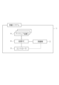
図2は、測量システム1の構成ブロック図である。測量システム1において、アイウェア装置4、測量機2、およびコントローラ3は、処理PC6に無線接続される(有線接続も可)。またコントローラ3は測量機2の遠隔操作装置であり、離れた場所から無線で測量機2に命令を送信するように構成されている。コントローラ3は処理PC6を介して測量機2と情報を送受信する構成にしてもよい。本実施形態においては、作業者は一人を想定しているが、アイウェア装置4の数は、特に限定されず、1つであってもよく複数であってもよい。アイウェア装置4が複数の場合、各アイウェア装置4は固有のID等で識別可能に構成される。
FIG. 2 is a configuration block diagram of the
(測量機2)
図3は測量機2の構成ブロック図である。測量機2は、モータドライブトータルステーションであり、水平角検出器21、鉛直角検出器22、水平回転駆動部23、鉛直回転駆動部24、演算制御部25、測距部26、追尾部27、通信部28、記憶部29、表示部18、入力部19を備える。
(Surveying instrument 2)
FIG. 3 is a configuration block diagram of the
水平角検出器21と鉛直角検出器22は、エンコーダである。水平角検出器21は、托架部2bの回転軸に設けられ、托架部2bの水平角を検出する。鉛直角検出器22は、望遠鏡2cの回転軸に設けられ、望遠鏡2cの鉛直角を検出する。
The
水平回転駆動部23および鉛直回転駆動部24はモータである。水平回転駆動部23は托架部2bの回転軸を動かし、鉛直回転駆動部24は、望遠鏡2cの回転軸を動かす。両駆動部の協働により、望遠鏡2cの向きが変更される。水平角検出器21と鉛直角検出器22とで、測角部を構成する。水平回転駆動部23および鉛直回転駆動部24とで、駆動部を構成する。
The horizontal
測距部26は、送光部と受光部を備え、例えば赤外パルスレーザ等の測距光を送光部から出射し、その反射光を受光部で受光し、測距光と内部参照光との位相から測距する。測距部は、プリズム測定のみならず、ノンプリズム測定も可能となっている。
The
追尾部27は、測距光とは異なる波長の赤外線レーザなどの追尾光として出射する追尾送光系と、CCDセンサまたはCMOSセンサなどのイメージセンサを有する追尾受光系を有する。追尾部27は、追尾光を含む風景画像と追尾光を除いた風景画像を取得し、両画像を演算制御部25に送る。演算制御部25は、両画像の差分からターゲット像の中心を求め、ターゲット像の中心と望遠鏡2cの視軸中心からの隔たりが一定値以内に収まる位置をターゲットの位置として検出し、常に望遠鏡2cがターゲットの方向を向くように、自動追尾する。
The
通信部28は、外部ネットワークとの通信を可能にするものであり、例えば、インターネットプロトコル(TCP/IP)を用いてインターネットを接続し、処理PC6およびコントローラ3と情報の送受信を行う。無線通信はこれに制限されず、既知の無線通信を使用することができる。測量機2が測定(測距・測角)した測定結果は、通信部28を介して処理PC6へ送られる。
The
演算制御部25は、CPUを備えたマイクロコントローラであり、制御として、通信部28を介した情報の送受信、水平回転駆動部23および鉛直回転駆動部24による各回転軸の駆動、測距部26による測距、水平角検出器21および鉛直角検出器22による測角、追尾部27による自動追尾を行う。
The
記憶部29は、ROMおよびRAMを備える。ROMには演算制御部25のためのプログラムが収納され、RAMにて各制御が実行される。
The
表示部18、入力部19は、測量機2のインターフェースである。入力部は、電源キー、数字キー、実行キーなどを有し、作業者が、測量機2の操作や測量機2に対する情報を入力できる。本実施形態においては、測量作業の指令や結果の確認などは、通信部28を介して処理PC6にて行うことも可能となっている。また、測量機2への命令は、コントローラ6からも可能となっている。
The
(コントローラ3)
図4は、コントローラ3の外観図です。図5は、コントローラ3の使用状態であり、ポール5に取付けられ、使用者がポール5を把持している状態を示す。図6は、コントローラ3の構成ブロック図である。
(Controller 3)
FIG. 4 is an external view of the
コントローラ3は、棒状のポール5に着脱可能に取付けられるための取付部31を有し、取付部31の挿通孔31aをポール5に挿通させて、締結部31bによりポール5の所望の高さ位置に取り外し可能に固定される。
The
コントローラ3は、測量機2の遠隔操作装置であり、チルトセンサ32と、通信部33と、入力部34、制御部35を備える。
The
通信部33は、通信部28と同等の構成を備え、測量機2および処理PC6と情報の送受信が可能となっている。アイウェア装置4と情報の送受信を行ってもよい。
The
チルトセンサ32は、基準状態からの傾斜角を計測するセンサである。本実施形態では、チルトセンサ32は加速度を計測可能な加速度センサで構成され、水平状態を基準として重力加速度を計測して、水平面に沿う一方向周りの傾きと、水平面に沿う一方向と直交する他方向周りの傾きとの両方を計測することが可能となっている。コントローラ3はポール5に取付けられた状態で使用されるため、チルトセンサ32は自身が取り付けられるポール5の鉛直状態から傾きを計測する。計測結果は、通信部33により処理PC6を介してアイウェア装置4へ送られ、電子気泡管として表示される。
The
入力部34は、操作用の押圧スイッチであり、十字キー34aとその中心に配置される円形スイッチ34bから成り、複数のスイッチにより、命令の選択/決定/キャンセルが可能な構成となっている。入力された命令は、測量機2へ送られる。
The
制御部35は、少なくともCPUおよびメモリ(RAM、ROM)を集積回路に実装したマイクロコンピュータである。制御部35は、チルトセンサ32の測定結果および入力部34で入力された情報を、通信部33を介して処理PC6または測量機に出力する。
The
コントローラ3は、全体が手のひらに収まる程度に小さくコンパクトに構成される。入力部34は挿通孔31aの近傍に設けられ、コントローラ3の筐体の表面で、入力のための複数のスイッチが全て直近の筐体外縁から5cm以内程度にまとまって配置されている。これは、作業者がポール5を把持した状態で、作業者の親指が載置される位置(作業者の親指の可動範囲内)であり、作業者はポール5を把持したまま、入力部34を操作できる形態となっている。コントローラ3は、作業者が少なくとも片手の数本の指および手の平でポール5を把持しつつ、残りの指(本実施形態では親指)でスイッチ操作ができるように構成されている。これにより、作業者はポール5を持って測定点Yを決定したときに、その姿勢のまま測量機2に測定(測距・測角)の実施命令を送ることができる。作業者が測量機2に命令を送る行動でポール5が傾いてしまうことが抑制される。作業者は目線も外さずに、両手でポール5を掴んだまま一連の行動が可能となる。入力部34は押圧スイッチで、決定の実施は直観的でわかりやすい。両手でポール5を把持して、位置決めを確実に行うことができ、なおかつそのままスイッチを押すことができるため、ポール5が傾くことを抑制できる。測量に本質的には不要な動作が省略され、時間短縮可能かつユーザーフレンドリーで、測量工程を効率良く行うことができる。
The
本実施形態においては、入力部34のスイッチの押圧方向は、取付部31、特に挿通孔31a(使用状態ではポール5)へ向かう方向となっている。このように、コントローラ3がポール5に取付けられた際に、おおむねポール5へ向かって指で押し付けるように構成されていると好ましい。これは把持されて固定されるポール5に向かって作業者がスイッチを押す構成とすると、作業者が操作しやすく、押圧行動で姿勢が傾くことを抑制できるためである。操作スイッチである入力部34の設けられた筐体の表面は鉛直からやや傾斜しており、ポール5を把持したときに、自然に載置される親指の位置に合わせて設けられ、作業者がよりスイッチを押しやすい構成となっている。また、必要押圧力を低くすることも作業者が押しやすく、好ましい。背面に決定スイッチを配置して、作業者が人差し指と親指で操作できるようにすると、操作性が向上し、好ましい。スピーカーや発光部(LED)を設け、操作に合わせて音や光が生ずる構成とすると、作業者が入力を確認でき、好ましい。
In this embodiment, the pressing direction of the switch of the
(アイウェア装置4)
図6はアイウェア装置4の外観斜視図である。図7はアイウェア装置4の構成ブロック図である。
(Eyewear device 4)
FIG. 6 is an external perspective view of the
アイウェア装置4は、作業者の頭部に装着されるウェアラブルデバイスであり、ディスプレイ41と、制御部42と、演算制御部43、通信部44、相対位置検出センサ45、相対方向検出センサ46、記憶部47、操作スイッチ48を備える。
The
ディスプレイ41は、作業者が装着したときに、作業者の両眼を覆うゴーグルレンズ型の透過ディスプレイである。一例として、ディスプレイ41は、ハーフミラーによる光学シースルーのディスプレイであり、現場風景(以下、「現物」という)の実像に重ねて、制御部42が受信した虚像が合成された映像を観察できるように構成されている。
The
通信部44は、前述の通信部と同等の構成を備え、測量機2および処理PC6と情報の送受信を行う。
The
相対位置検出センサ45は、測量現場に設置された、GPS用アンテナ、WiFi(登録商標)アクセスポイント、超音波発振器などから無線測位を行い、測量現場内でのアイウェア装置4の位置を検出する。
The relative
相対方向検出センサ46は、三軸加速度センサまたはジャイロセンサと、傾斜センサとの組み合わせから成る。相対方向検出センサ46は、上下方向をZ軸、左右方向をY軸、前後方向をX軸として、アイウェア装置4の傾きを検出する。
The relative
記憶部47は、例えばメモリカードである。記憶部47は、アイウェア装置4の演算制御部43が機能を実行するためのプログラムを格納している。操作スイッチ48は、例えば、アイウェア装置4の電源をON/OFFするための電源ボタンである。
The
制御部42は、少なくともCPUおよびメモリ(RAM、ROM)を集積回路に実装したマイクロコンピュータである。演算制御部43は、相対位置検出センサ45および相対方向検出センサ46の検出したアイウェア装置4の位置および方向の情報を処理PC6に、通信部44を介して出力する。また、処理PC6から測定点Yの位置データを受信して、ディスプレイ41上の現場の風景に重ねて表示する。また、コントローラ3のチルトセンサ32の測定結果を電子気泡管として表示させる。
The
(処理PC6)
図9は、処理PC6の構成ブロック図である。処理PC6は、汎用パーソナルコンピュータ、PLD(programmable Logic Device)などによる専用ハードウェア、タブレット端末、またはスマートフォンなどである。処理PC6は、通信部61と、表示部62と、操作部63と、記憶部64と、演算処理部65を有する。
(Processing PC 6)
FIG. 9 is a configuration block diagram of the
通信部61は、前述の通信部と同等の構造を有し、測量機2およびアイウェア装置4と情報の送受信を行う。
The
表示部62は、例えば液晶ディスプレイである。操作部63は、キーボード、マウスなどであり、種々の入力・選択・決定を可能にする。
The
記憶部64は、例えばHDDドライブである。記憶部64は、測量現場の情報、少なくとも、測量現場で測定すべき測定点Y(Y1,Y2,Y3・・・)の座標データである測定点データDを格納する。
The
演算処理部65は、少なくともCPUおよびメモリ(RAM、ROMなど)を集積回路に実装した制御ユニットである。演算処理部65には、同期計測部651がソフトウェア的に構成されている。 The arithmetic processing unit 65 is a control unit in which at least a CPU and memory (RAM, ROM, etc.) are mounted on an integrated circuit. A synchronization measurement unit 651 is configured in software in the arithmetic processing unit 65 .
同期計測部651は、測量機2の位置および方向に関する情報と、アイウェア装置4の位置・方向に関する情報を受信し、測量機2の座標空間と、測定点データDの座標空間と、アイウェア装置4の座標空間とが一致するように変換してアイウェア装置4に送信する。
The synchronous measurement unit 651 receives information about the position and direction of the surveying
以下、このように座標空間の異なる装置またはデータにおける位置および方向に関する情報の座標空間を一致させ、共通の基準点を原点とする空間で、それぞれの装置に関する相対位置・相対方向を管理することを同期という。 In the following, it is assumed that the coordinate spaces of information regarding positions and directions in devices or data with different coordinate spaces are matched in this way, and the relative positions and relative directions of each device are managed in a space with a common reference point as the origin. called synchronous.
(測定方法)
次に、測量システム1の使用の例(杭打ち作業)を説明する。図10は、測量システム1を用いた作業の工程フローである。図11は、ステップS102~S105の作業イメージ図である。図12および図13は測量システム1によるアイウェア装置4から見える画像の一例である。
(Measuring method)
Next, an example of use of the surveying system 1 (pile driving work) will be described. FIG. 10 is a process flow of work using the
まず、ステップS101で、前処理として、作業者はCADデータや杭打ちのため測定点データDを含む測量現場の情報を処理PC6に入力する。入力された情報は、処理PC6の記憶部64に収納される。
First, in step S101, as preprocessing, the operator inputs CAD data and information on the surveying site including the measurement point data D for piling into the
次に、ステップS102に移行して、作業者は、測量現場に、基準点と基準方向を設定する。基準点は、規定座標など、現場内の任意の点を選択する。基準方向は、基準点とは別の特徴点を任意に選択し、基準点-特徴点の方向とする。 Next, in step S102, the operator sets a reference point and a reference direction at the survey site. The reference point is any arbitrary point in the field, such as specified coordinates. For the reference direction, a feature point other than the reference point is arbitrarily selected, and the reference point-feature point direction is used.
次に、ステップS103に移行して、作業者は、測量機2の同期を行う。具体的には、作業者は、現場内の基準点に測量機2を設置し、上記基準点と上記特徴点を含む後方交会などの観測により、測量機2の絶対座標を把握する。測量機2は、座標情報を処理PC6に送信する。処理PC6の同期計測部651は、基準点の絶対座標を(x,y,z)=(0,0,0)に変換し、かつ基準方向を水平角0度と認識して、以後、測量機2からの情報に関して、基準点を原点とする空間で、測量機2の相対位置・相対方向を管理する。
Next, the operator proceeds to step S<b>103 to synchronize the surveying
次に、ステップS104に移行して、作業者は、アイウェア装置4の同期を行う。具体的には、基準点にアイウェア装置4を設置し、ディスプレイ41の中心を基準方向に一致させ、相対位置検出センサ45の(x,y,z)を(0,0,0)、かつ、相対方向検出センサ46の(roll,pitch,yaw)を(0,0,0)とする。処理PC6の同期計測部651は、以後、アイウェア装置4から取得するデータについて、基準点を原点とする空間で、アイウェア装置4の相対位置・相対方向を管理する。この結果、アイウェア装置4についても、基準点を原点とする空間で、相対位置・相対方向が管理される。
Next, in step S104, the operator synchronizes the
アイウェア装置4の同期は、上記方法に限定されず、例えば、アイウェア装置4に、アイウェア装置4の中心および方向軸を示したレーザ装置を設け、レーザをガイドにして、基準点および基準方向を一致させることにより行ってもよい。
Synchronization of the
あるいは、測量機2にアイウェア装置4の収納位置を設け、あらかじめアイウェア装置4と測量機2の相対関係を確定させておき、アイウェア装置4を測量機2の収納位置に収納した状態で、同期を開始することで、両者の相対関係を一致させてもよい。
Alternatively, a storage position for the
次に、ステップS105に移行して、アイウェア装置4のディスプレイ41に、同期された測定点データDが表示される。作業者がアイウェア装置4を装着して測量現場内を眺めと、アイウェア装置4の現物に対する相対位置・相対方向は処理PC6で管理されているから、処理PC6からアイウェア装置4に、現物(ディスプレイ41越しに見える風景の実像)に同期された測定点データDが虚像として表示される。
Next, the process proceeds to step S105, and the synchronized measurement point data D is displayed on the
図12は、アイウェア装置4を装着した作業者のディスプレイ41越しに見える表示の一例である。現物は実線、虚像は破線で示されている。図12に示すように、アイウェア装置4を装着した作業者は、測定点Yを、現物に重ねて確認することができる。即ち、各測定点Y(Y1、Y2、Y3・・・)は同期されて、現場に合わせて、対応箇所に虚像の逆三角マークM(M1、M2、M3・・・)として視認できるように示される。任意の点(図12では測量機2の設置点)からの所定距離毎にラインLが、マトリックス状に表示される。逆三角マーク(M1、M2、M3・・・)は、未測定と測定済みとでは色分けされる、作業者(アイウェア装置4)からの距離が大きいほど小さく表示されるなど、認識しやすく表示されると好ましい。
FIG. 12 is an example of a display seen through the
次に、ステップS106に移行して、次に測定すべき測定点Yn(杭打ち点)が決定される。作業者は、コントローラ3が装着されたポール5を把持し、ディスプレイ41に測定点Y(Y1,Y2,Y3・・・)として表示される逆三角マークM(M1、M2、M3・・・)から、入力部34で次の測定点Ynとして一つの逆三角マークMnを選択して決定する。例えば、選択中の逆三角マークMnはディスプレイ41上で点滅し、次の測定点Ynとして決定されると、当該逆三角マークMnはサークルCで囲まれるなど、作業者にわかりやすく表示される。測量機2は、決定された測定点Ynへ望遠鏡2cを向ける。
Next, the process proceeds to step S106 to determine the measurement point Yn (stakeout point) to be measured next. The operator grips the
次に、ステップS107に移行して、作業者は、測定すべき測定点Ynへポール5を持って移動する。ターゲット7が、測定点Ynから所定範囲(おおむね1m)まで近づくと、測量機2にターゲット7がロックされ、追尾部27が自動追尾を開始する。図13(A)はターゲット7がロックされた際にディスプレイ41に追加される虚像である。図13においては、全てディスプレイ41に表示される虚像であり、実線で示す。詳細なターゲット7の位置情報として、測定点Ynまでの距離と方向の詳細な画像R11、およびポール5の傾きを示す電子気泡管の画像R12が、ディスプレイ41に表示される。電子気泡管の色は、傾きの大きさに応じて色が変化すると好ましい。追尾中は随時データが送信され、リアルタイムにターゲット7の位置およびポール5の傾きがディスプレイ41に表示される。
Next, in step S107, the operator moves the
ディスプレイ41には、これに限られず、状況に応じて、入力可能な命令が画像で表示されてもよい。図13(B)では一例として追尾時の追加画像を示す。測距・測角を測量機2に命令する「測定」の画像R21、ターゲット7のロックが外れてしまったときのための「再追尾」の画像R21、メニュー画像に移行するための「メニュー」の画像R23、などの命令が文字のみの画像で示される。選択された命令はハイライト表示などにより、作業者に理解しやすく示される。
The
図13(C)に示される画像R3は、メニュー内容の一例であり、接続されるコントロールデバイスを示し、ディスプレイ41にアイコンとして表示される。例えば、画像R31は、コントローラ3を示す。画像R32は、グローブ型のコントロールデバイスを示す。本デバイスではグローブに設けられたセンサから、手の動きで測量機への命令が入力可能となっている。画像R33は、アイウェア装置4にオプションとして追加されるアイセンサであり、目の動きで命令の入力が可能となっている。画像R34は、スマートフォンや専用端末などの別体として構成されるコントロールデバイスである。本デバイスではディスプレイやスイッチを備え、スイッチから入力が可能となっている。
An image R3 shown in FIG. 13(C) is an example of the contents of the menu, shows connected control devices, and is displayed as an icon on the
測量システム1は、コントローラ3以外にも、1以上の命令入力可能なデバイス(コントロールデバイス)を備えることができ、複数のデバイスと同時接続可能で、接続されたデバイスのいずれからも命令の入力が可能となっている。本実施形態ではコントローラ3が測量機2のコントロールデバイスとして接続されており、画像R31は接続されていることを示すためにハイライト表示されている。測量システム1においては、複数のコントロールデバイスと測量機2とを接続可能に構成することで、作業者の熟練度や装置との相性に合わせて、快適な作業環境を構築できる。
In addition to the
次に、ステップS108に移行して、作業者は、ディスプレイ41に表示される画像R1およびR2で詳細な位置と、ポール5の傾きを把握して、測定点Ynにポール5をおおむね鉛直に立てる。作業者がそのままの姿勢でコントローラ3の入力部34(円形スイッチ34b)を押して、測定の開始の命令を測量機2に送ると、測量機2が測距および測角を開始し、測定結果が処理PC6に送られる。
Next, in step S108, the operator grasps the detailed position and inclination of the
次に、ステップS109で測定点の測定が完了すると、測定データは処理PC6に送られ、また次の測定すべき測定点Ynの選択にステップS106へ移動し、全ての測定点Yの測定が完了するまでステップS106~ステップS109を繰り返す。全ての測定点Yの測定を終えると、終了する。
Next, when the measurement of the measurement points is completed in step S109, the measurement data is sent to the
(作用効果)
上記に示すように、測量システム1によれば、アイウェア装置4に測定点Y(Y1、Y2、Y3・・・)が表示され、作業者は現物の風景に重ねて位置を把握できる。命令の入力も作業者がポール5を持ったままに行うことができる。無駄な作業が省略されて作業者一人での測量が効率化される。従来のように、ディスプレイを有するデバイスを所持する必要がなく、デバイス操作のために、ディスプレイへ目線をそらすことも、入力のために手を移動させたり、片手でポールを支える必要もない。また、押す動作により、命令指示が即座に確実に実施される。作業者は一人で測量の一連の作業をシームレスに行うことができ、作業効率が向上する。
(Effect)
As described above, according to the
(変形例1)
図14本実施の形態の変形例に係るコントローラ103の外観斜視図である。図15はコントローラ103の使用状態を示す。同じ構成を示すものは同じ符号を付して説明を省略する。
(Modification 1)
< Figure 14 >It is the appearance perspective view of
コントローラ103は、概略、コントローラ3と同等の構成を有し、入力部134は、ホイールスイッチを用いている。ホイールスイッチは、スイッチ本体であるホイール(回転盤)が、軸支かつ付勢されて保持されており、複数の入力動作が可能となっている。例えば、表面のホイールが回転することで「選択」、押圧されることで「決定」、長押しされることで「キャンセル」が入力される。入力については、一例でありこれに限られない。作業者がポール5を把持したまま、親指一本でコントローラ103に入力でき、容易に測量機2を遠隔操作することができる。
The
(変形例2)
図16本実施の形態の別の変形例に係るコントローラ203の外観斜視図である。図17はコントローラ203の使用状態を示す。同じ構成を示すものは同じ符号を付して説明を省略する。
(Modification 2)
16 is an external perspective view of
コントローラ203は、外殻が柔軟性を有する樹脂部材で構成されたシートから成り、一方向に長い帯状の外観を有し、全体が自在に変形可能となっている。表面中央に入力部34が設けられ、シートに覆われた内側に機器類が内蔵されている。使用時には、中央から端部に延びる取付部231がポール5に巻き付けられる。取付部231の裏面には面ファスナが設けられており、ポール5に容易に取り外し可能に装着される。コントローラ203はポール5の太さに関わらず簡単に取り付けられる。
The
以上、本発明の好ましい実施形態について述べたが、上記の実施形態は本発明の一例に過ぎない。例えば、演算処理部65および記憶部64を測量機2に含めることができる。これにより、処理PC6の機能を測量機2に集約でき、設定が容易になり、持ち運びや移動が容易になる。このように当業者の知識に基づいて変形させることが可能である。
Although preferred embodiments of the present invention have been described above, the above embodiments are merely examples of the present invention. For example, the arithmetic processing unit 65 and the
このような変形や実施例の組み合わせは当業者の知識に基づいて行うことができ、そのような形態も本発明の範囲に含まれる。 Such modifications and combinations of embodiments can be made based on the knowledge of those skilled in the art, and such forms are also included in the scope of the present invention.
1 :測量システム
2 :測量機
3 :コントローラ
4 :アイウェア装置
5 :ポール
6 :処理PC
7 :ターゲット
21 :水平角検出器
22 :鉛直角検出器
23 :水平回転駆動部
24 :鉛直回転駆動部
25 :演算制御部
26 :測距部
27 :追尾部
28 :通信部
29 :記憶部
31 :取付部
33 :通信部
34 :入力部
41 :ディスプレイ
42 :制御部
43 :演算制御部
44 :通信部
45 :相対位置検出センサ
46 :相対方向検出センサ
61 :通信部
64 :記憶部
65 :演算処理部
651 :同期計測部
Y :測定点
1: Surveying system 2: Surveying instrument 3: Controller 4: Eyewear device 5: Pole 6: Processing PC
7 : Target 21 : Horizontal angle detector 22 : Vertical angle detector 23 : Horizontal rotation driving unit 24 : Vertical rotation driving unit 25 : Calculation control unit 26 : Distance measuring unit 27 : Tracking unit 28 : Communication unit 29 : Storage unit 31 : Mounting part 33 : Communication part 34 : Input part 41 : Display 42 : Control part 43 : Calculation control part 44 : Communication part 45 : Relative position detection sensor 46 : Relative direction detection sensor 61 : Communication part 64 : Storage part 65 : Calculation Processing unit 651: synchronous measurement unit Y: measurement point
Claims (5)
前記ターゲット(7)までの距離を計測する測距部(26)と、前記測距部(26)の向く鉛直角と水平角を測角する測角部(21,22)と、前記測角部(21,22)の鉛直角および水平角を設定された角度に駆動する駆動部(23,24)と、通信部(28)と、入力された命令を実施する演算制御部(25)とを備え、前記ターゲット(5)の測距及び測角が可能な測量機(2)と、
前記ポール(7)に着脱可能に取付けられ、通信部(33)と、命令を入力する入力部(34)とを有し、前記測量機(2)と通信して前記測量機(2)に命令を送るコントローラ(3)と、
通信部(44)と、ディスプレイ(41)と、装置の位置を検出する相対位置検出センサ(45)と、装置の方向を検出する相対方向検出センサ(46)とを備えるアイウェア装置(4)と、
測量現場の測定点を記憶する記憶部(64)と、
前記アイウェア装置(4)の位置および方向に関する情報を受領し、前記測定点の座標と同期する同期計測部(651)を備える演算処理部(65)と、
を備え、
前記ディスプレイ(41)には、測量現場の風景に重ねて、前記演算処理部(65)が算出した前記測定点が表示され、前記コントローラ(3)から入力された命令により前記測量機(2)による測距および測角が実施される、
ことを特徴とする測量システム(1)。 a target (7), a pole (5) to which said target (7) is attached;
a distance measuring unit (26) for measuring the distance to the target (7); angle measuring units (21, 22) for measuring vertical and horizontal angles to which the distance measuring unit (26) faces; driving units (23, 24) for driving the vertical and horizontal angles of the units (21, 22) to set angles; a communication unit (28); and an arithmetic control unit (25) for executing an input command. a surveying instrument (2) capable of measuring the range and angle of the target (5);
It is detachably attached to the pole (7), has a communication section (33) and an input section (34) for inputting commands, and communicates with the surveying instrument (2) to send the surveying instrument (2). a controller (3) sending instructions;
An eyewear device (4) comprising a communication unit (44), a display (41), a relative position detection sensor (45) for detecting the position of the device, and a relative direction detection sensor (46) for detecting the orientation of the device. and,
a storage unit (64) for storing measurement points at a survey site;
an arithmetic processing unit (65) comprising a synchronous measurement unit (651) that receives information about the position and direction of the eyewear device (4) and synchronizes with the coordinates of the measurement point;
with
The display (41) displays the measurement points calculated by the arithmetic processing unit (65) superimposed on the scenery of the surveying site, and the surveying instrument (2) is displayed according to the command input from the controller (3). Ranging and angle measurements are performed by
A surveying system (1) characterized by:
前記入力部(34)は押圧スイッチであり、前記押圧スイッチは、押圧方向が前記取付部(31)に向かうように配置されている、
ことを特徴とする請求項1に記載の測量システム(1)。 The controller (3) has a mounting portion (31) for mounting to the pole (5),
The input portion (34) is a press switch, and the press switch is arranged so that the pressing direction is directed toward the mounting portion (31).
Surveying system (1) according to claim 1, characterized in that:
ことを特徴とする請求項1または請求項2に記載の測量システム。 The input section (34) is configured to operate within the movable range of at least the thumb and forefinger of the worker holding the pole (7) in a state in which the pole (5) to which the controller (6) is attached is supported. arranged to be enterable,
3. The surveying system according to claim 1 or 2, characterized in that:
ことを特徴とする請求項1~請求項3のいずれかに記載の測量システム(1)。 The surveying instrument (2) has a tracking unit (27) for automatically tracking the target (7), and when the target (7) is within a predetermined range from the measurement point, the surveying instrument (2) automatically tracks the target (7). The display (41) displays the position information of the target (7) in real time,
The surveying system (1) according to any one of claims 1 to 3, characterized in that:
ことを特徴とする請求項1~請求項4のいずれかに記載の測量システム(1)。 The storage unit (64) and the arithmetic processing unit (65) are provided in the surveying instrument (2),
The surveying system (1) according to any one of claims 1 to 4, characterized in that:
Priority Applications (3)
| Application Number | Priority Date | Filing Date | Title |
|---|---|---|---|
| JP2021155915A JP2023047024A (en) | 2021-09-24 | 2021-09-24 | surveying system |
| US17/940,558 US20230114255A1 (en) | 2021-09-24 | 2022-09-08 | Survey system |
| EP22197177.3A EP4160143A1 (en) | 2021-09-24 | 2022-09-22 | Survey system |
Applications Claiming Priority (1)
| Application Number | Priority Date | Filing Date | Title |
|---|---|---|---|
| JP2021155915A JP2023047024A (en) | 2021-09-24 | 2021-09-24 | surveying system |
Publications (1)
| Publication Number | Publication Date |
|---|---|
| JP2023047024A true JP2023047024A (en) | 2023-04-05 |
Family
ID=83438826
Family Applications (1)
| Application Number | Title | Priority Date | Filing Date |
|---|---|---|---|
| JP2021155915A Pending JP2023047024A (en) | 2021-09-24 | 2021-09-24 | surveying system |
Country Status (3)
| Country | Link |
|---|---|
| US (1) | US20230114255A1 (en) |
| EP (1) | EP4160143A1 (en) |
| JP (1) | JP2023047024A (en) |
Family Cites Families (4)
| Publication number | Priority date | Publication date | Assignee | Title |
|---|---|---|---|---|
| JP5060358B2 (en) | 2008-03-25 | 2012-10-31 | 株式会社トプコン | Surveying system |
| EP2431708A1 (en) * | 2010-09-16 | 2012-03-21 | Leica Geosystems AG | Geodesic measuring system with camera integrated in a remote control unit |
| EP3246660B1 (en) * | 2016-05-19 | 2019-10-30 | Hexagon Technology Center GmbH | System and method for referencing a displaying device relative to a surveying instrument |
| US20220283327A1 (en) * | 2018-12-13 | 2022-09-08 | Leica Geosystems Ag | Measurement method, measurement systems and auxiliary measurement instruments |
-
2021
- 2021-09-24 JP JP2021155915A patent/JP2023047024A/en active Pending
-
2022
- 2022-09-08 US US17/940,558 patent/US20230114255A1/en active Pending
- 2022-09-22 EP EP22197177.3A patent/EP4160143A1/en active Pending
Also Published As
| Publication number | Publication date |
|---|---|
| US20230114255A1 (en) | 2023-04-13 |
| EP4160143A1 (en) | 2023-04-05 |
Similar Documents
| Publication | Publication Date | Title |
|---|---|---|
| US10416708B2 (en) | Accessory and information processing system | |
| US10940573B2 (en) | Hand-held tool system | |
| US9377303B2 (en) | Surveying appliance and method having a targeting functionality which is based on the orientation of a remote control unit and is scalable | |
| JP4626671B2 (en) | Input device and control system | |
| JP2004108939A (en) | Remote control system of survey airplane | |
| EP2466440B1 (en) | Display control program, display control apparatus, display control system, and display control method | |
| CN103502772A (en) | Coordinate positioning machine controller | |
| JP7240996B2 (en) | Surveying system and surveying method using eyewear device | |
| CN107153446A (en) | Virtual reality system and tracker device | |
| JP2018036720A (en) | Virtual space observation system, method and program | |
| JPWO2009072471A1 (en) | Input device, control device, control system, control method, and handheld device | |
| US20090128485A1 (en) | Pointing input device | |
| JP2010142404A (en) | Game program, and game apparatus | |
| JP2013210906A (en) | Control method, control device and program | |
| JP2023047024A (en) | surveying system | |
| JP2021177157A (en) | Eyewear display system | |
| JP5945297B2 (en) | GAME PROGRAM AND GAME DEVICE | |
| JP2023047025A (en) | surveying system | |
| US20110069007A1 (en) | Pointing device | |
| JP2023047026A (en) | surveying system | |
| JP3223025U (en) | Controller for electronic equipment | |
| CN111061384A (en) | Touch control pen with range finder | |
| US11681370B2 (en) | Handheld controller and control method | |
| JP7442285B2 (en) | Surveying system and method using eyewear equipment | |
| JP2021177156A (en) | Eyewear display system |
Legal Events
| Date | Code | Title | Description |
|---|---|---|---|
| RD02 | Notification of acceptance of power of attorney |
Free format text: JAPANESE INTERMEDIATE CODE: A7422 Effective date: 20231120 |