JP2023047026A - surveying system - Google Patents
surveying system Download PDFInfo
- Publication number
- JP2023047026A JP2023047026A JP2021155917A JP2021155917A JP2023047026A JP 2023047026 A JP2023047026 A JP 2023047026A JP 2021155917 A JP2021155917 A JP 2021155917A JP 2021155917 A JP2021155917 A JP 2021155917A JP 2023047026 A JP2023047026 A JP 2023047026A
- Authority
- JP
- Japan
- Prior art keywords
- unit
- surveying
- target
- input
- display
- Prior art date
- Legal status (The legal status is an assumption and is not a legal conclusion. Google has not performed a legal analysis and makes no representation as to the accuracy of the status listed.)
- Pending
Links
- 230000033001 locomotion Effects 0.000 claims abstract description 20
- 238000005259 measurement Methods 0.000 claims description 67
- 238000012545 processing Methods 0.000 claims description 36
- 238000004891 communication Methods 0.000 claims description 23
- 239000003550 marker Substances 0.000 claims description 19
- 238000001514 detection method Methods 0.000 claims description 14
- 230000004424 eye movement Effects 0.000 claims description 11
- 238000003384 imaging method Methods 0.000 claims description 9
- 230000001360 synchronised effect Effects 0.000 claims description 9
- 210000000887 face Anatomy 0.000 claims description 2
- 238000010586 diagram Methods 0.000 description 13
- 238000000034 method Methods 0.000 description 9
- 230000003287 optical effect Effects 0.000 description 5
- 230000006870 function Effects 0.000 description 3
- 230000004397 blinking Effects 0.000 description 2
- 210000003128 head Anatomy 0.000 description 2
- 238000012986 modification Methods 0.000 description 2
- 230000004048 modification Effects 0.000 description 2
- 230000001133 acceleration Effects 0.000 description 1
- 238000013459 approach Methods 0.000 description 1
- 230000005540 biological transmission Effects 0.000 description 1
- 238000004040 coloring Methods 0.000 description 1
- 230000000694 effects Effects 0.000 description 1
- 238000009434 installation Methods 0.000 description 1
- 239000004973 liquid crystal related substance Substances 0.000 description 1
- 239000011159 matrix material Substances 0.000 description 1
- 238000007781 pre-processing Methods 0.000 description 1
- 238000002271 resection Methods 0.000 description 1
- 230000000007 visual effect Effects 0.000 description 1
- 239000002699 waste material Substances 0.000 description 1
Images


Classifications
-
- G—PHYSICS
- G01—MEASURING; TESTING
- G01C—MEASURING DISTANCES, LEVELS OR BEARINGS; SURVEYING; NAVIGATION; GYROSCOPIC INSTRUMENTS; PHOTOGRAMMETRY OR VIDEOGRAMMETRY
- G01C3/00—Measuring distances in line of sight; Optical rangefinders
-
- G—PHYSICS
- G06—COMPUTING; CALCULATING OR COUNTING
- G06F—ELECTRIC DIGITAL DATA PROCESSING
- G06F3/00—Input arrangements for transferring data to be processed into a form capable of being handled by the computer; Output arrangements for transferring data from processing unit to output unit, e.g. interface arrangements
- G06F3/01—Input arrangements or combined input and output arrangements for interaction between user and computer
- G06F3/011—Arrangements for interaction with the human body, e.g. for user immersion in virtual reality
- G06F3/013—Eye tracking input arrangements
-
- G—PHYSICS
- G01—MEASURING; TESTING
- G01C—MEASURING DISTANCES, LEVELS OR BEARINGS; SURVEYING; NAVIGATION; GYROSCOPIC INSTRUMENTS; PHOTOGRAMMETRY OR VIDEOGRAMMETRY
- G01C1/00—Measuring angles
- G01C1/02—Theodolites
-
- G—PHYSICS
- G01—MEASURING; TESTING
- G01C—MEASURING DISTANCES, LEVELS OR BEARINGS; SURVEYING; NAVIGATION; GYROSCOPIC INSTRUMENTS; PHOTOGRAMMETRY OR VIDEOGRAMMETRY
- G01C15/00—Surveying instruments or accessories not provided for in groups G01C1/00 - G01C13/00
- G01C15/002—Active optical surveying means
-
- G—PHYSICS
- G01—MEASURING; TESTING
- G01C—MEASURING DISTANCES, LEVELS OR BEARINGS; SURVEYING; NAVIGATION; GYROSCOPIC INSTRUMENTS; PHOTOGRAMMETRY OR VIDEOGRAMMETRY
- G01C15/00—Surveying instruments or accessories not provided for in groups G01C1/00 - G01C13/00
- G01C15/02—Means for marking measuring points
- G01C15/06—Surveyors' staffs; Movable markers
-
- G—PHYSICS
- G01—MEASURING; TESTING
- G01S—RADIO DIRECTION-FINDING; RADIO NAVIGATION; DETERMINING DISTANCE OR VELOCITY BY USE OF RADIO WAVES; LOCATING OR PRESENCE-DETECTING BY USE OF THE REFLECTION OR RERADIATION OF RADIO WAVES; ANALOGOUS ARRANGEMENTS USING OTHER WAVES
- G01S17/00—Systems using the reflection or reradiation of electromagnetic waves other than radio waves, e.g. lidar systems
- G01S17/66—Tracking systems using electromagnetic waves other than radio waves
-
- G—PHYSICS
- G02—OPTICS
- G02B—OPTICAL ELEMENTS, SYSTEMS OR APPARATUS
- G02B27/00—Optical systems or apparatus not provided for by any of the groups G02B1/00 - G02B26/00, G02B30/00
- G02B27/01—Head-up displays
- G02B27/0101—Head-up displays characterised by optical features
-
- G—PHYSICS
- G06—COMPUTING; CALCULATING OR COUNTING
- G06F—ELECTRIC DIGITAL DATA PROCESSING
- G06F3/00—Input arrangements for transferring data to be processed into a form capable of being handled by the computer; Output arrangements for transferring data from processing unit to output unit, e.g. interface arrangements
- G06F3/01—Input arrangements or combined input and output arrangements for interaction between user and computer
- G06F3/011—Arrangements for interaction with the human body, e.g. for user immersion in virtual reality
- G06F3/012—Head tracking input arrangements
-
- G—PHYSICS
- G02—OPTICS
- G02B—OPTICAL ELEMENTS, SYSTEMS OR APPARATUS
- G02B27/00—Optical systems or apparatus not provided for by any of the groups G02B1/00 - G02B26/00, G02B30/00
- G02B27/01—Head-up displays
- G02B27/0101—Head-up displays characterised by optical features
- G02B2027/0141—Head-up displays characterised by optical features characterised by the informative content of the display
Landscapes
- Engineering & Computer Science (AREA)
- Physics & Mathematics (AREA)
- General Physics & Mathematics (AREA)
- Theoretical Computer Science (AREA)
- General Engineering & Computer Science (AREA)
- Radar, Positioning & Navigation (AREA)
- Remote Sensing (AREA)
- Human Computer Interaction (AREA)
- Electromagnetism (AREA)
- Optics & Photonics (AREA)
- Computer Networks & Wireless Communication (AREA)
- Eye Examination Apparatus (AREA)
- User Interface Of Digital Computer (AREA)
Abstract
Description
本発明は、一人で測量を行う作業者の作業効率を向上させる測量システムに関する。 TECHNICAL FIELD The present invention relates to a surveying system that improves the work efficiency of a worker who surveys alone.
近年は作業者が一人(ワンマン)で測量を行うことも多くなっている(例えば、特許文献1)。作業者が表示部と入力部を備えたデバイスを携帯し、ターゲット付きのポールを持って測定点へ移動して、デバイスの表示部で測定点を確認し、入力部から遠隔で測量機に測距・測角を指示することで、作業者一人で測量をすることが可能となっている。 In recent years, surveying is often conducted by a single operator (one-man) (for example, Patent Document 1). A worker carries a device equipped with a display and an input unit, holds a pole with a target and moves to a measurement point, confirms the measurement point on the display of the device, and remotely sends a survey to the surveying instrument from the input unit. By instructing distance and angle measurement, it is possible for a single operator to perform surveying.
しかし、作業者は、デバイスの表示部を確認しながら移動し、測定のときには入力部から測定の命令を入力せねばならず、一連の動作に時間がかかるという問題があった。 However, the operator has to move while checking the display of the device, and has to input the measurement command from the input section when measuring, which causes a problem that a series of operations takes time.
本発明は、このような問題を改善するために成されたものであり、作業者一人での測量の作業効率を向上させる測量システムを提供する。 SUMMARY OF THE INVENTION The present invention has been made to solve such problems, and provides a surveying system that improves the work efficiency of surveying by a single operator.
上記問題を解決するため、本開示のある態様では、ターゲット(7)と、前記ターゲット(7)が取り付けられるポール(5)と、前記ターゲット(7)までの距離を計測する測距部(26)と、前記測距部(26)の向く鉛直角と水平角を測角する測角部(21,22)と、前記測角部(21,22)の鉛直角および水平角を設定された角度に駆動する駆動部(23,24)と、通信部(28)と、入力された命令を実施する演算制御部(25)とを備え、前記ターゲット(5)の測距及び測角が可能な測量機(2)と、装着者の目の動きを検出するアイセンサ(31)と、各種命令を入力する入力部(34)と、通信部(44)と、ディスプレイ(41)と、装置の位置を検出する相対位置検出センサ(45)と、装置の方向を検出する相対方向検出センサ(46)とを備えるアイウェア装置(4)と、測量現場の測定点を記憶する記憶部(64)と、前記アイウェア装置(4)の位置および方向に関する情報を受領し、前記測定点の座標と同期する同期計測部(651)を備える演算処理部(65)と、を備え、前記ディスプレイ(41)には、測量現場の風景に重ねて、前記演算処理部(65)が算出した前記測定点が表示され、前記アイセンサ(31)が検出した目の動きに応じた命令が入力部(34)より入力され、前記入力部(34)からの命令により前記測量機(2)による測距および測角が実施される、測量システム(1)を提供する。 In order to solve the above problem, in one aspect of the present disclosure, a target (7), a pole (5) to which the target (7) is attached, and a distance measuring unit (26) that measures the distance to the target (7) ), angle measuring units (21, 22) for measuring the vertical angle and horizontal angle to which the distance measuring unit (26) faces, and the vertical and horizontal angles of the angle measuring units (21, 22) are set. Equipped with a driving unit (23, 24) for driving an angle, a communication unit (28), and an arithmetic control unit (25) for executing an input command, capable of measuring the range and angle of the target (5) a surveying instrument (2), an eye sensor (31) for detecting eye movement of the wearer, an input section (34) for inputting various commands, a communication section (44), a display (41), and equipment An eyewear device (4) comprising a relative position detection sensor (45) for detecting a position and a relative direction detection sensor (46) for detecting the direction of the device, and a storage section (64) for storing measurement points on a survey site. and an arithmetic processing unit (65) including a synchronous measurement unit (651) that receives information about the position and direction of the eyewear device (4) and synchronizes with the coordinates of the measurement point, and the display (41 ) displays the measurement points calculated by the arithmetic processing unit (65) superimposed on the scenery of the survey site, and commands corresponding to eye movements detected by the eye sensor (31) are input to the input unit (34). To provide a surveying system (1) in which the surveying instrument (2) performs distance measurement and angle measurement according to commands from the input unit (34).
この態様によれば、アイウェア装置で測定点を測量現場の風景に重ねて確認でき、さらにポールを把持したままの姿勢で、目の動きで測量機に命令を送ることができる。測量に必要な行動を無駄なく実施でき、作業者一人での測量の作業効率が向上する。 According to this aspect, the eyewear device can superimpose the measurement point on the scenery of the surveying site and confirm it, and furthermore, the command can be sent to the surveying instrument by the movement of the eye while holding the pole. Actions required for surveying can be carried out without waste, and the work efficiency of surveying by a single worker is improved.
また、ある態様では、前記アイセンサ(31)は、装着者の視線を検知する視線センサであり、前記(41)ディスプレイには、前記視線センサに基づいた視線マーカが表示され、前記ディスプレイには、前記入力部(34)として各種の命令が画像表示され、前記視線マーカにより選択された画像が命令として入力されるように構成した。この態様によれば、視線マーカにより、ディスプレイを見ながら命令を入力できる。 In one aspect, the eye sensor (31) is a line-of-sight sensor that detects the line of sight of the wearer, the display (41) displays a line-of-sight marker based on the line-of-sight sensor, and the display: Various commands are image-displayed as the input unit (34), and an image selected by the line-of-sight marker is input as a command. According to this aspect, the line-of-sight marker allows the command to be input while looking at the display.
また、ある態様では、前記アイセンサ(31)は目の動きを検出する撮像装置(132)と、前記撮像装置が検出した動きと予め登録された複数のモーションとのマッチング判定を行う判定部(133)とを有し、前記入力部(34)は、前記判定部(133)がマッチング判定したモーションに対応する命令を入力するように構成した。目の動きだけで命令を入力でき、視線を外さず、そのままの姿勢で命令を入力できる。 In one aspect, the eye sensor (31) includes an imaging device (132) that detects eye movement, and a determination unit (133) that determines matching between the movement detected by the imaging device and a plurality of pre-registered motions. ), and the input unit (34) is configured to input a command corresponding to the motion determined as matching by the determination unit (133). You can enter commands just by moving your eyes, and you can enter commands without changing your line of sight.
また、ある態様では、前記測量機(2)は、前記ターゲット(7)を自動追尾する追尾部(27)を有し、前記ターゲット(7)が前記測定点から所定範囲内にあると、自動で追尾を行い、前記ディスプレイ(41)には、リアルタイムに前記ターゲット(7)の位置情報が表示されるように構成した。この態様によれば、ターゲットがロックされた状態では、詳しい位置情報が追加されるため、ポールを測定位置により高精度に短時間で設置できる。 In one aspect, the surveying instrument (2) has a tracking section (27) that automatically tracks the target (7), and when the target (7) is within a predetermined range from the measurement point, the surveying instrument (2) automatically and the position information of the target (7) is displayed in real time on the display (41). According to this aspect, when the target is locked, the detailed position information is added, so the pole can be set at the measurement position with high accuracy in a short time.
また、ある態様では、前記記憶部(64)および前記演算処理部(65)は、前記測量機(2)に備えられるように構成した。ソフトウェア的、またはハードウェア的に測量機に含まれることで、構成要素を減らすことができる。設定を測量機で行うことができるため、全体の構成をシンプルにすることができる。 In one aspect, the storage section (64) and the arithmetic processing section (65) are configured to be provided in the surveying instrument (2). By being included in the surveying instrument in terms of software or hardware, the number of components can be reduced. Since the settings can be made with the surveying instrument, the overall configuration can be simplified.
以上の説明から明らかなように、本発明によれば、作業者一人での測量の作業効率を向上させる測量システムを提供することができる。 As is clear from the above description, according to the present invention, it is possible to provide a surveying system that improves the work efficiency of surveying by a single operator.
以下、本開示の構成の具体的な実施形態を、図面を参照しながら説明する。実施の形態は、発明を限定するものではなく例示であって、実施の形態に記述されるすべての特徴やその組み合わせは、必ずしも発明の本質的なものであるとは限らない。また、同一の構成を持つものは同一の符号を付して、説明を省略する。 Hereinafter, specific embodiments of the configuration of the present disclosure will be described with reference to the drawings. The embodiments are illustrative rather than limiting the invention, and not all features and combinations thereof described in the embodiments are necessarily essential to the invention. Moreover, those having the same configuration are denoted by the same reference numerals, and the description thereof is omitted.
(実施形態)
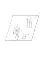
図1は、本発明の好適な実施形態である測量システム1の外観斜視図であり、測量現場での作業イメージを示している。本実施形態に係る測量システム1は、ターゲット7が装着されたポール5、測量機2、処理PC6、アイウェア装置4を備える。
(embodiment)
FIG. 1 is an external perspective view of a
測量機2は、基準点中心上に三脚を用いて設置される。測量機2は、整準器の上に設けられた基盤部2aと、基盤部2aを軸H-H周りに水平に回転する托架部2bと、托架部2bの中央で軸V-V周りに鉛直回転する望遠鏡2cとを有する。
The
アイウェア装置4は、作業者の頭部に装着される。処理PC6は、測量現場内に設置される。
The
ポール5は下端を測定点に概ね鉛直に設置して使用される。ターゲット7は、測量機2の測量目標物であり、全方位から入射される光を再帰反射する光学特性を有している。ターゲット7の光学中心(光学的な反射点)はポール5の中心軸上となるように取り付けられており、取り付け高(ポール5下端から光学中心までの距離)は既知である。
The
図2は、測量システム1の構成ブロック図である。測量システム1において、アイウェア装置4、測量機2、処理PC6は、相互に無線接続される(有線接続も可)。アイウェア装置4は、測量機2の遠隔操作機能を備えており、離れた場所から無線で測量機2に命令を送信するように構成されている。本実施形態においては、作業者は一人を想定しているが、アイウェア装置4の数は、特に限定されず、1つであってもよく複数であってもよい。アイウェア装置4が複数の場合、各アイウェア装置4は固有のIDなどで識別可能に構成される。
FIG. 2 is a configuration block diagram of the
(測量機2)
図3は測量機2の構成ブロック図である。測量機2は、モータドライブトータルステーションであり、水平角検出器21、鉛直角検出器22、水平回転駆動部23、鉛直回転駆動部24、演算制御部25、測距部26、追尾部27、通信部28、記憶部29、表示部18、入力部19を備える。
(Surveying instrument 2)
FIG. 3 is a configuration block diagram of the
水平角検出器21と鉛直角検出器22は、エンコーダである。水平角検出器21は、托架部2bの回転軸に設けられ、托架部2bの水平角を検出する。鉛直角検出器22は、望遠鏡2cの回転軸に設けられ、望遠鏡2cの鉛直角を検出する。
The
水平回転駆動部23および鉛直回転駆動部24はモータである。水平回転駆動部23は托架部2bの回転軸を動かし、鉛直回転駆動部24は、望遠鏡2cの回転軸を動かす。両駆動部の協働により、望遠鏡2cの向きが変更される。水平角検出器21と鉛直角検出器22とで、測角部を構成する。水平回転駆動部23および鉛直回転駆動部24とで、駆動部を構成する。
The horizontal
測距部26は、送光部と受光部を備え、例えば赤外パルスレーザ等の測距光を送光部から出射し、その反射光を受光部で受光し、測距光と内部参照光との位相から測距する。測距部は、プリズム測定のみならず、ノンプリズム測定も可能となっている。
The
追尾部27は、測距光とは異なる波長の赤外線レーザなどの追尾光として出射する追尾送光系と、CCDセンサまたはCMOSセンサなどのイメージセンサを有する追尾受光系を有する。追尾部27は、追尾光を含む風景画像と追尾光を除いた風景画像を取得し、両画像を演算制御部25に送る。演算制御部25は、両画像の差分からターゲット像の中心を求め、ターゲット像の中心と望遠鏡2cの視軸中心からの隔たりが一定値以内に収まる位置をターゲットの位置として検出し、常に望遠鏡2cがターゲットの方向を向くように、自動追尾する。
The
通信部28は、外部ネットワークとの通信を可能にするものであり、例えば、インターネットプロトコル(TCP/IP)を用いてインターネットを接続し、処理PC6およびアイウェア装置4と情報の送受信を行う。無線通信はこれに制限されず、既知の無線通信を使用することができる。測量機2が測定(測距・測角)した測定結果は、通信部28を介して処理PC6へ送られる。
The
演算制御部25は、CPUを備えたマイクロコントローラであり、制御として、通信部28を介した情報の送受信、水平回転駆動部23および鉛直回転駆動部24による各回転軸の駆動、測距部26による測距、水平角検出器21および鉛直角検出器22による測角、追尾部27による自動追尾を行う。
The
記憶部29は、ROMおよびRAMを備える。ROMには演算制御部25のためのプログラムが収納され、RAMにて各制御が実行される。
The
表示部18、入力部19は、測量機2のインターフェースである。入力部は、電源キー、数字キー、実行キーなどを有し、作業者が、測量機2の操作や測量機2に対する情報を入力できる。本実施形態においては、測量作業の指令や結果の確認などは、通信部28を介して処理PC6にて行うことも可能となっている。また、測量機2への命令は、アイウェア装置4からも可能となっている。
The
(アイウェア装置4)
図4はアイウェア装置4の外観斜視図である。図5はアイウェア装置4の構成ブロック図である。
(Eyewear device 4)
FIG. 4 is an external perspective view of the
アイウェア装置4は、作業者の頭部に装着されるウェアラブルデバイスであり、ディスプレイ41、制御部42と、演算制御部43、通信部44、相対位置検出センサ45、相対方向検出センサ46、記憶部47、アイセンサ31、および入力部34を備える。
The
ディスプレイ41は、作業者が装着したときに、作業者の両眼を覆うゴーグルレンズ型の透過ディスプレイである。一例として、ディスプレイ41は、ハーフミラーによる光学シースルーのディスプレイであり、現場風景(以下、「現物」という)の実像に重ねて、制御部42が投影させた虚像を観察できるように構成されている。
The
通信部44は、前述の通信部と同等の構成を備え、測量機2および処理PC6と情報の送受信を行う。
The
相対位置検出センサ45は、測量現場に設置された、GPS用アンテナ、WiFi(登録商標)アクセスポイント、超音波発振器などから無線測位を行い、測量現場内でのアイウェア装置4の位置を検出する。
The relative
相対方向検出センサ46は、三軸加速度センサまたはジャイロセンサと、傾斜センサとの組み合わせから成る。相対方向検出センサ46は、上下方向をZ軸、左右方向をY軸、前後方向をX軸として、アイウェア装置4の傾きを検出する。
The relative
記憶部47は、例えばメモリカードである。記憶部47は、アイウェア装置4の演算制御部43が機能を実行するためのプログラムを格納している。
The
アイセンサ31は、装着者の視線を検知する視線センサであり、ディスプレイ41の後ろ側(装着者の顔の方向)に設けられている。アイセンサ31は、CCDやCMOSなどの撮像装置と画像処理装置を含み、目頭位置と虹彩位置の位置関係に基づき管理者の視線を検出し、ディスプレイ41における装着者の視線の位置座標を検出する。ディスプレイ41には、アイセンサ31が検出した視線の位置座標に対応する場所に、視線マーカEMが表示される。
The
入力部34は、ソフトウェア的に構成され、ディスプレイ41上に、「測量」「再追尾」などの命令の内容がアイコンや文字列などの画像(虚像)として表示される。アイセンサ31と組み合わせて用いられ、作業者が表示された画像に視線マーカEMを所定時間以上合わせることで、命令は実行される。所定の視線の動きを命令決定の動作としてもよい。例えば、視線が消失する「まばたき」を、ゆっくり二度することで、視線マーカEMに選択されていた命令が実行されるように構成してもよい。
The
制御部42は、少なくともCPUおよびメモリ(RAM、ROM)を集積回路に実装したマイクロコンピュータである。演算制御部43は、相対位置検出センサ45および相対方向検出センサ46の検出したアイウェア装置4の位置および方向の情報を処理PC6に、通信部44を介して出力する。処理PC6から測定点Yの位置データを受信して、ディスプレイ41上の現場の風景に重ねて表示する。また、アイセンサ31の検出した視線の位置座標から、作業者の視線に合わせてディスプレイ41に視線マーカEMを表示し、状況に合わせて命令を画像として表示し、決定された命令の処理を実行する。
The
(処理PC6)
図6は、処理PC6の構成ブロック図である。処理PC6は、汎用パーソナルコンピュータ、PLD(programmable Logic Device)などによる専用ハードウェア、タブレット端末、またはスマートフォンなどである。処理PC6は、通信部61と、表示部62と、操作部63と、記憶部64と、演算処理部65を有する。
(Processing PC 6)
FIG. 6 is a configuration block diagram of the
通信部61は、前述の通信部と同等の構造を有し、測量機2およびアイウェア装置4と情報の送受信を行う。
The
表示部62は、例えば液晶ディスプレイである。操作部63は、キーボード、マウスなどであり、種々の入力・選択・決定を可能にする。
The
記憶部64は、例えばHDDドライブである。記憶部64は、測量現場の情報、少なくとも、測量現場で測定すべき測定点Y(Y1,Y2,Y3・・・)の座標データである測定点データDを格納する。
The
演算処理部65は、少なくともCPUおよびメモリ(RAM、ROMなど)を集積回路に実装した制御ユニットである。演算処理部65には、同期計測部651がソフトウェア的に構成されている。 The arithmetic processing unit 65 is a control unit in which at least a CPU and memory (RAM, ROM, etc.) are mounted on an integrated circuit. A synchronization measurement unit 651 is configured in software in the arithmetic processing unit 65 .
同期計測部651は、測量機2の位置および方向に関する情報と、アイウェア装置4の位置・方向に関する情報を受信し、測量機2の座標空間と、測定点データDの座標空間と、アイウェア装置4の座標空間とが一致するように変換してアイウェア装置4に送信する。
The synchronous measurement unit 651 receives information about the position and direction of the surveying
以下、このように座標空間の異なる装置またはデータにおける位置および方向に関する情報の座標空間を一致させ、共通の基準点を原点とする空間で、それぞれの装置に関する相対位置・相対方向を管理することを同期という。 In the following, it is assumed that the coordinate spaces of information regarding positions and directions in devices or data with different coordinate spaces are matched in this way, and the relative positions and relative directions of each device are managed in a space with a common reference point as the origin. called synchronous.
(測定方法)
次に、測量システム1の使用の例(杭打ち作業)を説明する。図7は、測量システム1を用いた作業の工程フローである。図8は、ステップS102~S105の作業イメージ図である。図9および図10は測量システム1によるアイウェア装置4から見える画像の一例である。
(Measuring method)
Next, an example of use of the surveying system 1 (pile driving work) will be described. FIG. 7 is a process flow of work using the
まず、ステップS101で、前処理として、作業者はCADデータや杭打ちのため測定点データDを含む測量現場の情報を処理PC6に入力する。入力された情報は、処理PC6の記憶部64に収納される。
First, in step S101, as preprocessing, the operator inputs CAD data and information on the surveying site including the measurement point data D for piling into the
次に、ステップS102に移行して、作業者は、測量現場に、基準点と基準方向を設定する。基準点は、規定座標など、現場内の任意の点を選択する。基準方向は、基準点とは別の特徴点を任意に選択し、基準点-特徴点の方向とする。 Next, in step S102, the operator sets a reference point and a reference direction at the survey site. The reference point is any arbitrary point in the field, such as specified coordinates. For the reference direction, a feature point other than the reference point is arbitrarily selected, and the reference point-feature point direction is used.
次に、ステップS103に移行して、作業者は、測量機2の同期を行う。具体的には、作業者は、現場内の基準点に測量機2を設置し、上記基準点と上記特徴点を含む後方交会などの観測により、測量機2の絶対座標を把握する。測量機2は、座標情報を処理PC6に送信する。処理PC6の同期計測部651は、基準点の絶対座標を(x,y,z)=(0,0,0)に変換し、かつ基準方向を水平角0度と認識して、以後、測量機2からの情報に関して、基準点を原点とする空間で、測量機2の相対位置・相対方向を管理する。
Next, the operator proceeds to step S<b>103 to synchronize the surveying
次に、ステップS104に移行して、作業者は、アイウェア装置4の同期を行う。具体的には、基準点にアイウェア装置4を設置し、ディスプレイ41の中心を基準方向に一致させ、相対位置検出センサ45の(x,y,z)を(0,0,0)、かつ、相対方向検出センサ46の(roll,pitch,yaw)を(0,0,0)とする。処理PC6の同期計測部651は、以後、アイウェア装置4から取得するデータについて、基準点を原点とする空間で、アイウェア装置4の相対位置・相対方向を管理する。この結果、アイウェア装置4についても、基準点を原点とする空間で、相対位置・相対方向が管理される。
Next, in step S104, the operator synchronizes the
アイウェア装置4の同期は、上記方法に限定されず、例えば、アイウェア装置4に、アイウェア装置4の中心および方向軸を示したレーザ装置を設け、レーザをガイドにして、基準点および基準方向を一致させることにより行ってもよい。
Synchronization of the
あるいは、測量機2にアイウェア装置4の収納位置を設け、あらかじめアイウェア装置4と測量機2の相対関係を確定させておき、アイウェア装置4を測量機2の収納位置に収納した状態で、同期を開始することで、両者の相対関係を一致させてもよい。
Alternatively, a storage position for the
次に、ステップS105に移行して、アイウェア装置4のディスプレイ41に、同期された測定点データDが表示される。作業者がアイウェア装置4を装着して測量現場内を眺めと、アイウェア装置4の現物に対する相対位置・相対方向は処理PC6で管理されているから、処理PC6からアイウェア装置4に、現物(ディスプレイ41越しに見える風景の実像)に同期された測定点データDが虚像として表示される。また、アイウェア装置4を装着した作業者の視線がアイセンサ31に検知され、ディスプレイ41の視線対応位置に視線マーカEMが表示される。
Next, the process proceeds to step S105, and the synchronized measurement point data D is displayed on the
図9は、アイウェア装置4を装着した作業者のディスプレイ41越しに見える表示の一例である。現物は実線、虚像は破線で示されている。図9に示すように、アイウェア装置4を装着した作業者は、測定点Yを、現物に重ねて確認することができる。即ち、各測定点Y(Y1、Y2、Y3・・・)は同期されて、現場に合わせて、対応箇所に虚像の逆三角形マークM(M1、M2、M3・・・)として視認できるように示される。任意の点(図12では測量機2の設置点)からの所定距離毎にラインLが、マトリックス状に表示される。逆三角形マークM(M1、M2、M3・・・)は、未測定と測定済みとでは色分けされる、作業者(アイウェア装置4)からの距離が大きいほど小さく表示されるなど、認識しやすく表示されると好ましい。
FIG. 9 shows an example of a display seen through the
さらに、ディスプレイ41には、作業者の視線座標位置に、視線マーカEMが表示される。図9では墨で着色した円形で示されている。作業者の視線移動に対応して、視線マーカEMもリアルタイムに移動する。
Furthermore, the
次に、ステップS106に移行して、次に測定すべき測定点Yn(杭打ち点)が決定される。作業者は、ディスプレイ41に測定点Y(Y1,Y2,Y3・・・)として表示される逆三角形マークM(M1,M2,M3・・・)から、次の測定点Ynとして一つの逆三角形マークMnを選択して決定する。作業者は、次に測定すべき測定点Ynの逆三角形マークMnを見つめて、視線マーカEMを逆三角形マークMnに合わせる。視線マーカEMが逆三角形マークMnに重なると、逆三角形マークMnは選択された状態となり点滅するため、そのまま視線を外さず所定時間(3秒程度)が経過すると、次の測定点Ynとして決定される。次の測定点Ynとして選択された当該逆三角形マークMnは、サークルCで囲まれるなど、作業者にわかりやすく表示される。本ステップでは逆三角形マークMnは選択可能な入力部34でもあり、対応位置に選択肢としてディスプレイ41に表示される。測量機2は、決定された測定点Ynへ望遠鏡2cを向ける。
Next, the process proceeds to step S106, and a measurement point Yn (stakeout point) to be measured next is determined. The operator selects one inverted triangle as the next measurement point Yn from the inverted triangle marks M (M1, M2, M3, . . . ) displayed as measurement points Y (Y1, Y2, Y3, . Mark Mn is selected and determined. The operator gazes at the inverted triangular mark Mn of the measurement point Yn to be measured next, and aligns the line-of-sight marker EM with the inverted triangular mark Mn. When the line-of-sight marker EM overlaps the inverted triangular mark Mn, the inverted triangular mark Mn is selected and blinks. Therefore, if the line of sight is not removed and a predetermined time (about 3 seconds) elapses, the next measurement point Yn is determined. be. The inverted triangular mark Mn selected as the next measurement point Yn is surrounded by a circle C, and is displayed in an easy-to-understand manner for the operator. In this step, the inverted triangular mark Mn is also the
次に、ステップS107に移行して、作業者は、測定すべき測定点Ynへポール5を持って移動する。ターゲット7が、測定点Ynから所定範囲(おおむね1m)まで近づくと、測量機2にターゲット7がロックされ、追尾部27が自動追尾を開始する。図10(A)はターゲット7がロックされた際にディスプレイ41に追加される虚像である。図10においては、全てディスプレイに41表示される虚像であり、実線で示す。詳細なターゲット7の位置情報として、測定点Ynまでの距離と方向の詳細が画像R1として表示され、さらに入力部34として入力可能な選択肢が画像R2としてディスプレイ41に表示される。
Next, in step S107, the operator moves the
追尾中は随時データが送信され、リアルタイムにターゲット7の位置が画像R1に表示される。測量機2への命令も可能であり、状況に応じて入力可能な命令が画像表示される。図10(B)に一例として、追尾時の命令の画像R2を示す。ターゲット7のロックが外れてしまったときは「再追尾」の画像R22を、メニュー画面に移行する場合には「メニュー」の画像R23を、それぞれ視線マーカEMで選択することで、各種命令が実行される。
Data is transmitted at any time during tracking, and the position of the
図10(C)に示される画像R3は、メニュー内容の一例であり、接続されるコントロールデバイスを示し、ディスプレイ41にアイコンとして表示される。例えば、画像R31は、ポール5に取り付けされる小型のコントールデバイスを示す。本デバイスでは入力のみ可能で、小型であるため作業者はポール5を把持したまま命令の入力が可能である。画像R32は、グローブ型のコントロールデバイスを示す。本デバイスではグローブに設けられたセンサから、手の動きで測量機への命令が入力可能となっている。画像R33は、アイウェア装置4を示し、目の動きで命令の入力が可能となっている。画像R34は、スマートフォンや専用端末などの別体として構成されるコントロールデバイスである。本デバイスではディスプレイやスイッチを備え、スイッチから入力が可能となっている。
An image R3 shown in FIG. 10(C) is an example of the contents of the menu, shows connected control devices, and is displayed on the
測量システム1は、1以上の命令入力可能なデバイス(コントロールデバイス)を備えることができ、複数のデバイスと同時接続可能で、接続されたデバイスのいずれからも命令の入力が可能となっている。本実施形態ではアイウェア装置4が測量機2のコントロールデバイスとして接続されており、画像R33は接続されていることを示すためにハイライト表示されている。測量システム1においては、複数のコントロールデバイスと測量機2とを接続可能に構成することで、作業者の熟練度や装置との相性に合わせて、快適な作業環境を構築できる。
The
次に、ステップS108に移行して、作業者は、ディスプレイ41に表示される画像R1で詳細な位置を把握して、測定点Ynにポール5をおおむね鉛直に立てる。作業者がそのままの姿勢で、「測定」の画像R21を見つめて視線マーカEMを合わせ、そのまま数秒見つめ続けると、測定の開始の命令が測量機2に送られ、測量機2が測距および測角を開始し、測定結果が処理PC6に送られる。
Next, in step S108, the operator grasps the detailed position from the image R1 displayed on the
次に、ステップS109で測定点の測定が完了すると、測定データは処理PC6に送られ、また次の測定すべき測定点Ynの選択にステップS106へ移動し、全ての測定点Yの測定が完了するまでステップS106~ステップS109を繰り返す。全ての測定点Yの測定を終えると、終了する。
Next, when the measurement of the measurement points is completed in step S109, the measurement data is sent to the
(作用効果)
上記に示すように、測量システム1によれば、アイウェア装置4に測定点Y(Y1、Y2、Y3・・・)が表示され、作業者は現物の風景に重ねて位置を把握できる。アイウェア装置4から視線により命令の入力ができるため、作業者はポール5を持ったまま動かずに命令の入力ができる。無駄な作業が省略されて作業者一人での測量が効率化される。従来のように、ディスプレイや入力部を有するデバイスを所持する必要がなく、デバイス操作のために、ディスプレイへ目線をそらすことも、入力のために手を移動させたり、片手だけでポールを支える必要もない。作業者は一人で測量の一連の作業をシームレスに行うことができ、作業効率が向上する。
(Effect)
As described above, according to the
入力部34の画像については、視線マーカEMが選択中である場合には、点滅、ハイライト、色付けなどにより、選択が視認されるように構成されると好ましい。選択中にあと何秒見つめ続ければよいかをゲージで表示する、スピーカを設けて、操作に合わせて音を発生させるなど、作業者に入力をわかりやすく確認できるように構成されると、より好ましい。
It is preferable that the image of the
(第2実施形態)
図11は本実施の第2実施形態の係る測量システム101に備えられるアイウェア装置104の外観斜視図である。図12はアイウェア装置104の構成ブロック図である。同じ構成を示すものは同じ符号を付して説明を省略する。
(Second embodiment)
FIG. 11 is an external perspective view of an
測量システム101は、概略、測量システム1と同等の構成を有し、アイウェア装置104を有する。アイウェア装置104もアイウェア装置4と、概略同等の構成を有し、入力部134、および、アイセンサ131として撮像装置132および判定部133を有する。
The surveying system 101 has roughly the same configuration as the
撮像装置132は、装着者の目の動きを検出し、判定部133は、撮像装置132が検出した動きと予め登録された複数のモーション(目の動きのパターン)とのマッチング判定を行う。入力部134は、判定部133がマッチング判定したモーションに対応する命令を入力する。本実施形態では、視線マーカEMは用いずに、目の動きのパターンから、直接に各種命令を入力する。
The
例えば、作業者がウィンクすることで「選択(次へ)」、所定時間以上両眼を閉じることで「キャンセル(戻る)」、両眼をゆっくり二度まばたきすることで「決定」など、あらかじめ登録された目の動きのパターンと命令の内容を対応させておく。作業者が所定の目の動きをすることで、これをアイセンサ131に検知させて、測量機2へ命令を入力する。入力可能な命令をディスプレイ41に画像として表示させ、選択されている命令(画像)を点滅やハイライト表示させると好ましい。判定されて実行された命令が理解されるように、操作に合わせて音や光を発すると、なお好ましい。ディスプレイ41への視線マーカEMの表示の必要がなくなり、よりシンプルな構成となる。作業者は、目の動きだけで測量機2を操作可能となる。
For example, the operator can wink to "select (next)," close both eyes for a predetermined time to "cancel (return)," blink both eyes slowly twice to "confirm," etc. The pattern of the eye movement and the content of the command are made to correspond. When the operator makes a predetermined eye movement, it is detected by the
以上、本発明の好ましい実施形態について述べたが、上記の実施形態は本発明の一例に過ぎない。例えば、演算処理部65および記憶部64を測量機2に含めることができる。これにより、処理PC6の機能を測量機2に集約でき、設定が容易になり、持ち運びや移動が容易になる。このように当業者の知識に基づいて変形させることが可能である。
Although preferred embodiments of the present invention have been described above, the above embodiments are merely examples of the present invention. For example, the arithmetic processing unit 65 and the
このような変形や実施例の組み合わせは当業者の知識に基づいて行うことができ、そのような形態も本発明の範囲に含まれる。 Such modifications and combinations of embodiments can be made based on the knowledge of those skilled in the art, and such forms are also included in the scope of the present invention.
1 :測量システム
2 :測量機
4 :アイウェア装置
5 :ポール
6 :処理PC
7 :ターゲット
19 :入力部
21 :水平角検出器
22 :鉛直角検出器
23 :水平回転駆動部
24 :鉛直回転駆動部
25 :演算制御部
26 :測距部
27 :追尾部
28 :通信部
29 :記憶部
31 :アイセンサ
32 :判定部
34 :入力部
41 :ディスプレイ
42 :制御部
43 :演算制御部
44 :通信部
45 :相対位置検出センサ
46 :相対方向検出センサ
47 :記憶部
61 :通信部
64 :記憶部
65 :演算処理部
132 :撮像装置
133 :判定部
134 :入力部
651 :同期計測部
EM :視線マーカ
Y :測定点
1: Surveying system 2: Surveying instrument 4: Eyewear device 5: Pole 6: Processing PC
7 : Target 19 : Input Unit 21 : Horizontal Angle Detector 22 : Vertical Angle Detector 23 : Horizontal Rotation Drive Unit 24 : Vertical Rotation Drive Unit 25 : Calculation Control Unit 26 : Ranging Unit 27 : Tracking Unit 28 : Communication Unit 29 : Storage unit 31 : Eye sensor 32 : Judgment unit 34 : Input unit 41 : Display 42 : Control unit 43 : Calculation control unit 44 : Communication unit 45 : Relative position detection sensor 46 : Relative direction detection sensor 47 : Storage unit 61 : Communication unit 64: storage unit 65: arithmetic processing unit 132: imaging device 133: determination unit 134: input unit 651: synchronous measurement unit EM: line-of-sight marker Y: measurement point
Claims (5)
前記ターゲット(7)までの距離を計測する測距部(26)と、前記測距部(26)の向く鉛直角と水平角を測角する測角部(21,22)と、前記測角部(21,22)の鉛直角および水平角を設定された角度に駆動する駆動部(23,24)と、通信部(28)と、入力された命令を実施する演算制御部(25)とを備え、前記ターゲット(5)の測距及び測角が可能な測量機(2)と、
装着者の目の動きを検出するアイセンサ(31)と、各種命令を入力する入力部(34)と、通信部(44)と、ディスプレイ(41)と、装置の位置を検出する相対位置検出センサ(45)と、装置の方向を検出する相対方向検出センサ(46)とを備えるアイウェア装置(4)と、
測量現場の測定点を記憶する記憶部(64)と、
前記アイウェア装置(4)の位置および方向に関する情報を受領し、前記測定点の座標と同期する同期計測部(651)を備える演算処理部(65)と、
を備え、
前記ディスプレイ(41)には、測量現場の風景に重ねて、前記演算処理部(65)が算出した前記測定点が表示され、前記アイセンサ(31)が検出した目の動きに応じた命令が入力部(34)より入力され、前記入力部(34)からの命令により前記測量機(2)による測距および測角が実施される、
ことを特徴とする測量システム(1)。 a target (7), a pole (5) to which said target (7) is attached;
a distance measuring unit (26) for measuring the distance to the target (7); angle measuring units (21, 22) for measuring vertical and horizontal angles to which the distance measuring unit (26) faces; driving units (23, 24) for driving the vertical and horizontal angles of the units (21, 22) to set angles; a communication unit (28); and an arithmetic control unit (25) for executing an input command. a surveying instrument (2) capable of measuring the range and angle of the target (5);
An eye sensor (31) that detects the movement of the wearer's eyes, an input section (34) that inputs various commands, a communication section (44), a display (41), and a relative position detection sensor that detects the position of the device. an eyewear device (4) comprising (45) and a relative orientation sensor (46) for detecting the orientation of the device;
a storage unit (64) for storing measurement points at a survey site;
an arithmetic processing unit (65) comprising a synchronous measurement unit (651) that receives information about the position and direction of the eyewear device (4) and synchronizes with the coordinates of the measurement point;
with
The display (41) displays the measurement points calculated by the arithmetic processing unit (65) superimposed on the landscape of the survey site, and commands are input according to eye movements detected by the eye sensor (31). input from a unit (34), and distance measurement and angle measurement are performed by the surveying instrument (2) according to a command from the input unit (34);
A surveying system (1) characterized by:
ことを特徴とする請求項1に記載の測量システム(1)。 The eye sensor (31) is a line-of-sight sensor that detects the line of sight of the wearer, the display (41) displays a line-of-sight marker based on the line-of-sight sensor, and the display (41) receives the input As a part (34), various commands are displayed as images, and the images selected by the line-of-sight markers are input as commands;
Surveying system (1) according to claim 1, characterized in that:
ことを特徴とする請求項1に記載の測量システム(1)。 The eye sensor (31) has an imaging device (132) that detects eye movement, and a determination unit (133) that performs matching determination between the movement detected by the imaging device and a plurality of motions registered in advance, The input unit (34) inputs a command corresponding to the motion determined by the determination unit (133) as matching.
Surveying system (1) according to claim 1, characterized in that:
ことを特徴とする請求項1~請求項3のいずれかに記載の測量システム(1)。 The surveying instrument (2) has a tracking unit (27) for automatically tracking the target (7), and when the target (7) is within a predetermined range from the measurement point, the surveying instrument (2) automatically tracks the target (7). The display (41) displays the position information of the target (7) in real time,
The surveying system (1) according to any one of claims 1 to 3, characterized in that:
ことを特徴とする請求項1~請求項4のいずれかに記載の測量システム(1)。 The storage unit (64) and the arithmetic processing unit (65) are provided in the surveying instrument (2),
The surveying system (1) according to any one of claims 1 to 4, characterized in that:
Priority Applications (3)
| Application Number | Priority Date | Filing Date | Title |
|---|---|---|---|
| JP2021155917A JP2023047026A (en) | 2021-09-24 | 2021-09-24 | surveying system |
| US17/940,595 US11966508B2 (en) | 2021-09-24 | 2022-09-08 | Survey system |
| EP22196356.4A EP4155878A1 (en) | 2021-09-24 | 2022-09-19 | Survey system |
Applications Claiming Priority (1)
| Application Number | Priority Date | Filing Date | Title |
|---|---|---|---|
| JP2021155917A JP2023047026A (en) | 2021-09-24 | 2021-09-24 | surveying system |
Publications (1)
| Publication Number | Publication Date |
|---|---|
| JP2023047026A true JP2023047026A (en) | 2023-04-05 |
Family
ID=83362541
Family Applications (1)
| Application Number | Title | Priority Date | Filing Date |
|---|---|---|---|
| JP2021155917A Pending JP2023047026A (en) | 2021-09-24 | 2021-09-24 | surveying system |
Country Status (3)
| Country | Link |
|---|---|
| US (1) | US11966508B2 (en) |
| EP (1) | EP4155878A1 (en) |
| JP (1) | JP2023047026A (en) |
Family Cites Families (12)
| Publication number | Priority date | Publication date | Assignee | Title |
|---|---|---|---|---|
| US6094625A (en) * | 1997-07-03 | 2000-07-25 | Trimble Navigation Limited | Augmented vision for survey work and machine control |
| US20030014212A1 (en) | 2001-07-12 | 2003-01-16 | Ralston Stuart E. | Augmented vision system using wireless communications |
| JP5060358B2 (en) * | 2008-03-25 | 2012-10-31 | 株式会社トプコン | Surveying system |
| JP4824793B2 (en) * | 2009-07-06 | 2011-11-30 | 東芝テック株式会社 | Wearable terminal device and program |
| US9557812B2 (en) * | 2010-07-23 | 2017-01-31 | Gregory A. Maltz | Eye gaze user interface and calibration method |
| CN107430403B (en) | 2015-03-31 | 2021-03-23 | 深圳市大疆创新科技有限公司 | System and method with geo-fencing device level |
| EP3246660B1 (en) * | 2016-05-19 | 2019-10-30 | Hexagon Technology Center GmbH | System and method for referencing a displaying device relative to a surveying instrument |
| EP3460394B1 (en) * | 2017-09-26 | 2020-06-03 | Hexagon Technology Center GmbH | Surveying instrument, augmented reality (ar)-system and method for referencing an ar-device relative to a reference system |
| US20220283327A1 (en) | 2018-12-13 | 2022-09-08 | Leica Geosystems Ag | Measurement method, measurement systems and auxiliary measurement instruments |
| JP7240996B2 (en) * | 2019-09-18 | 2023-03-16 | 株式会社トプコン | Surveying system and surveying method using eyewear device |
| JP2022007185A (en) * | 2020-06-25 | 2022-01-13 | 株式会社トプコン | Eyewear display system |
| US11221217B1 (en) * | 2020-07-09 | 2022-01-11 | Trimble Inc. | Layout workflow with augmented reality and optical prism |
-
2021
- 2021-09-24 JP JP2021155917A patent/JP2023047026A/en active Pending
-
2022
- 2022-09-08 US US17/940,595 patent/US11966508B2/en active Active
- 2022-09-19 EP EP22196356.4A patent/EP4155878A1/en active Pending
Also Published As
| Publication number | Publication date |
|---|---|
| EP4155878A1 (en) | 2023-03-29 |
| US11966508B2 (en) | 2024-04-23 |
| US20230098762A1 (en) | 2023-03-30 |
Similar Documents
| Publication | Publication Date | Title |
|---|---|---|
| AU2018330755B2 (en) | Displaying a virtual image of a building information model | |
| EP3460394B1 (en) | Surveying instrument, augmented reality (ar)-system and method for referencing an ar-device relative to a reference system | |
| JP7240996B2 (en) | Surveying system and surveying method using eyewear device | |
| JP6399692B2 (en) | Head mounted display, image display method and program | |
| CN113348428A (en) | Virtual object display device and virtual object display method | |
| JP2022007185A (en) | Eyewear display system | |
| JP2018063540A (en) | Method for assisting in input to application providing content using head-mounted device, program for sing computer to implement the same, and content display device | |
| JP7234011B2 (en) | Location information display device and surveying system | |
| EP3910407A1 (en) | Eyewear display system and eyewear display method | |
| JP2023047026A (en) | surveying system | |
| JP7341861B2 (en) | Management system and method using eyewear device | |
| EP4155666A1 (en) | Survey system | |
| US20230114255A1 (en) | Survey system | |
| JP7442285B2 (en) | Surveying system and method using eyewear equipment | |
| US11663786B2 (en) | Eyewear display system | |
| WO2022208600A1 (en) | Wearable terminal device, program, and display method | |
| JP2023077246A (en) | Survey support system and survey support method | |
| JP2024027006A (en) | Surveying system, surveying method, and program for surveying | |
| JP2018063704A (en) | Method for assisting in input to application providing content using head-mounted device, program for sing computer to implement the same, and content display device |
Legal Events
| Date | Code | Title | Description |
|---|---|---|---|
| RD02 | Notification of acceptance of power of attorney |
Free format text: JAPANESE INTERMEDIATE CODE: A7422 Effective date: 20231120 |