JP2023032278A - Video display device and method for controlling the same, and program - Google Patents
Video display device and method for controlling the same, and program Download PDFInfo
- Publication number
- JP2023032278A JP2023032278A JP2021138310A JP2021138310A JP2023032278A JP 2023032278 A JP2023032278 A JP 2023032278A JP 2021138310 A JP2021138310 A JP 2021138310A JP 2021138310 A JP2021138310 A JP 2021138310A JP 2023032278 A JP2023032278 A JP 2023032278A
- Authority
- JP
- Japan
- Prior art keywords
- display device
- information
- diopter
- user
- changing
- Prior art date
- Legal status (The legal status is an assumption and is not a legal conclusion. Google has not performed a legal analysis and makes no representation as to the accuracy of the status listed.)
- Pending
Links
Images


Classifications
-
- G—PHYSICS
- G02—OPTICS
- G02B—OPTICAL ELEMENTS, SYSTEMS OR APPARATUS
- G02B27/00—Optical systems or apparatus not provided for by any of the groups G02B1/00 - G02B26/00, G02B30/00
- G02B27/01—Head-up displays
- G02B27/0179—Display position adjusting means not related to the information to be displayed
-
- G—PHYSICS
- G02—OPTICS
- G02B—OPTICAL ELEMENTS, SYSTEMS OR APPARATUS
- G02B27/00—Optical systems or apparatus not provided for by any of the groups G02B1/00 - G02B26/00, G02B30/00
- G02B27/01—Head-up displays
- G02B27/017—Head mounted
- G02B27/0172—Head mounted characterised by optical features
-
- G—PHYSICS
- G02—OPTICS
- G02B—OPTICAL ELEMENTS, SYSTEMS OR APPARATUS
- G02B27/00—Optical systems or apparatus not provided for by any of the groups G02B1/00 - G02B26/00, G02B30/00
- G02B27/01—Head-up displays
- G02B27/0101—Head-up displays characterised by optical features
- G02B2027/0132—Head-up displays characterised by optical features comprising binocular systems
- G02B2027/0134—Head-up displays characterised by optical features comprising binocular systems of stereoscopic type
-
- G—PHYSICS
- G02—OPTICS
- G02B—OPTICAL ELEMENTS, SYSTEMS OR APPARATUS
- G02B27/00—Optical systems or apparatus not provided for by any of the groups G02B1/00 - G02B26/00, G02B30/00
- G02B27/01—Head-up displays
- G02B27/0101—Head-up displays characterised by optical features
- G02B2027/0138—Head-up displays characterised by optical features comprising image capture systems, e.g. camera
-
- G—PHYSICS
- G02—OPTICS
- G02B—OPTICAL ELEMENTS, SYSTEMS OR APPARATUS
- G02B27/00—Optical systems or apparatus not provided for by any of the groups G02B1/00 - G02B26/00, G02B30/00
- G02B27/01—Head-up displays
- G02B27/0101—Head-up displays characterised by optical features
- G02B2027/014—Head-up displays characterised by optical features comprising information/image processing systems
-
- G—PHYSICS
- G02—OPTICS
- G02B—OPTICAL ELEMENTS, SYSTEMS OR APPARATUS
- G02B27/00—Optical systems or apparatus not provided for by any of the groups G02B1/00 - G02B26/00, G02B30/00
- G02B27/01—Head-up displays
- G02B27/0179—Display position adjusting means not related to the information to be displayed
- G02B2027/0187—Display position adjusting means not related to the information to be displayed slaved to motion of at least a part of the body of the user, e.g. head, eye
Landscapes
- Physics & Mathematics (AREA)
- General Physics & Mathematics (AREA)
- Optics & Photonics (AREA)
- Testing, Inspecting, Measuring Of Stereoscopic Televisions And Televisions (AREA)
Abstract
Description
本発明は、映像表示装置における視度調整の技術に関する。 The present invention relates to technology for adjusting visibility in an image display device.
使用者が頭部に装着して使用する映像表示装置や、使用者が眼鏡のように装着して使用する映像表示装置がある。使用者の眼の近傍に表示部が配置され、使用者の左右それぞれの眼に対して視差映像の表示処理が行われる。表示される視差映像を使用者が視認することによって、視差映像に表示された物体についての立体感が得られる。 2. Description of the Related Art There are video display devices worn by users on their heads and video display devices worn by users like eyeglasses. A display unit is arranged in the vicinity of the user's eyes, and parallax image display processing is performed for each of the user's left and right eyes. By visually recognizing the displayed parallax images, the user can obtain a stereoscopic effect of the object displayed in the parallax images.
特許文献1では、表示画像の違和感を軽減し、長時間の連続使用における観察者の酔いを軽減するための技術が開示されている。使用者の眼の状態に基づいて、表示された視差映像の内、網膜に焦点が合っている部分を除く他の部分には、ぼやけるように画像処理が施される。 Japanese Patent Application Laid-Open No. 2004-200000 discloses a technique for reducing the discomfort of a displayed image and reducing the motion sickness of an observer during continuous use for a long period of time. Based on the user's eye condition, image processing is performed so that other portions of the displayed parallax image, excluding the portion focused on the retina, are blurred.
ところで人間がある物体を見る際には、2つの眼の視線が交差する角度である輻輳角と、眼球内の水晶体の焦点距離が、物体から眼までの距離に応じて変化する。現実空間においては、輻輳角と水晶体の焦点距離との関係が常におおよそ一致する。 By the way, when a human sees an object, the convergence angle, which is the angle at which the lines of sight of the two eyes intersect, and the focal length of the crystalline lens in the eyeball change according to the distance from the object to the eye. In the real space, the relationship between the angle of convergence and the focal length of the crystalline lens is always approximately the same.
特許文献1に開示された従来技術では、表示される視差映像によって物体位置の変化は表現されるが、映像表示装置の光軸方向における視差映像の表示位置(視度)は常に一定である。従って、視差映像として表示される、ある物体の像を使用者が見ると、使用者の輻輳角は、その物体の位置に応じて変化する。この時、現実空間での経験に基づいて水晶体の焦点距離は輻輳角の大きさに応じて変化する。この場合、水晶体の焦点距離と映像表示装置の視度とが不一致となる可能性がある。結果として使用者は、表示された視差映像に焦点が合わず、鮮明に見ることが困難となる等、良好な視認性が確保できない場合がある。 In the prior art disclosed in Patent Document 1, changes in object positions are represented by the displayed parallax images, but the display position (visibility) of the parallax images in the optical axis direction of the image display device is always constant. Therefore, when a user sees an image of a certain object displayed as a parallax image, the user's angle of convergence changes according to the position of the object. At this time, the focal length of the crystalline lens changes according to the magnitude of the convergence angle based on experience in the real space. In this case, there is a possibility that the focal length of the lens and the dioptric power of the image display device do not match. As a result, the user may not be able to focus on the displayed parallax image, and it may be difficult to see the image clearly.
従って、映像表示装置の視度調整では、装置内のレンズを駆動する方法等により、使用者の輻輳角を定める視差映像内の物体の位置に応じて視度を変更することが望ましい。しかしながら、使用者の輻輳角と水晶体の焦点距離との関係は、年齢や視力等による影響のために個人差がある。仮に映像表示装置にて視度を視差映像内の表示物体の位置に応じて一律に変更したとすると、使用者によっては、表示された視差映像に焦点が合わず、鮮明に見ることが困難となってしまい、良好な視認性を確保できない。また、映像表示装置が消費電力を節減しない通常モードであるか、または長時間の使用のための省電力モードであるかによって、適切なレンズ駆動速度が異なる場合がある。このような使用者の違い(個人差)や映像表示装置の動作モード等を含む使用状態によって、適切な視度変更動作が異なる場合がある。
本発明の目的は、使用状態に対応した視度変更を可能とする映像表示装置を提供することである。
Therefore, in adjusting the visibility of the image display device, it is desirable to change the visibility according to the position of the object in the parallax image that determines the convergence angle of the user, for example, by driving the lens in the device. However, the relationship between the user's convergence angle and the focal length of the crystalline lens differs from person to person due to influences such as age and visual acuity. If the diopter of the image display device were uniformly changed according to the position of the displayed object in the parallax image, it would be difficult for some users to see the displayed parallax image clearly. and good visibility cannot be ensured. Also, the appropriate lens drive speed may differ depending on whether the video display device is in a normal mode that does not save power consumption or in a power saving mode for long-term use. Appropriate dioptric power changing operations may differ depending on such differences in users (individual differences) and usage conditions including the operation mode of the image display device.
SUMMARY OF THE INVENTION It is an object of the present invention to provide an image display device capable of changing dioptric power in accordance with usage conditions.
本発明の実施形態の映像表示装置は、使用者の左眼および右眼に対してそれぞれ映像を表示する第1および第2の表示光学系を備える映像表示装置であって、前記第1および第2の表示光学系による映像における表示物体の物体位置を算出する算出手段と、前記物体位置および前記映像表示装置の使用状態の情報に基づいて前記第1および第2の表示光学系に係る視度の変更を行う視度変更手段と、を備えることを特徴とする。 An image display device according to an embodiment of the present invention is an image display device comprising first and second display optical systems for displaying images to the left eye and right eye of a user, respectively. Calculation means for calculating an object position of a display object in an image by the display optical system of 2, and diopter associated with the first and second display optical systems based on the information on the object position and the usage state of the image display device. and dioptric power changing means for changing the
本発明の映像表示装置によれば、使用状態に対応した視度変更を可能とする表示装置を提供することができる。 According to the image display device of the present invention, it is possible to provide a display device capable of changing the dioptric power corresponding to the state of use.
以下に、本発明の実施形態を、添付図面に基づいて詳細に説明する。実施形態では、頭部装着型や眼鏡型等の映像表示装置における視度変更制御の例を示すが、本発明は視差映像の表示が可能な各種形態の映像表示装置への適用が可能である。なお、視差映像は視点の異なる複数の画像からなる、視差を有する映像である。 Embodiments of the present invention will be described in detail below with reference to the accompanying drawings. In the embodiments, an example of diopter change control in a video display device such as a head-mounted type or glasses type is shown, but the present invention can be applied to various types of video display devices capable of displaying parallax video. . Note that the parallax video is a video with parallax, which is composed of a plurality of images from different viewpoints.
図1は、本実施形態にかかわる映像表示装置1の概略構成を示す図である。各部の詳細は後述するが映像データ取得部100、表示処理部101、視度変更指示部106、物体位置算出部108、使用者情報記録部109、動作モード記録部110は例えばCPU等の1つ以上のプロセッサがプログラムを読出し実行することで実現される。映像表示装置1を、使用者が頭部に装着して使用する形態と、眼鏡のように装着して使用する形態がある。いずれの形態でも、使用者の左眼2a,右眼2bに対して近傍に映像表示装置1を固定することができる。なお、使用者の左眼2aに関連する構成要素の符号には記号aを付記し、使用者の右眼2bに関連する構成要素の符号には記号bを付記することによって区別する。
FIG. 1 is a diagram showing a schematic configuration of a video display device 1 according to this embodiment. Although the details of each unit will be described later, the image
映像表示装置1は映像データ取得部100と表示処理部101を備える。映像データ取得部100は表示用の映像データを外部装置やネットワーク等を通じて取得する。表示処理部101は取得された映像データに対して表示倍率の調整処理等を行う。処理された映像データは、2つの表示部102a,102bに送られて表示される。例えば、映像データを2つの表示部102a,102bへの各データに分割して表示する構成がある。この構成に限定されることなく、1つの表示部の画面を2つに分割して、分割された画面に映像データを表示する構成でもよい。
The video display device 1 includes a video
映像表示装置1は、左眼2a、右眼2bにそれぞれ対応する第1および第2の表示光学系を備える。第1の表示光学系はレンズ103aを有し、第2の表示光学系はレンズ103bを有する。表示部102a,102bに表示された映像はそれぞれに対応するレンズ103a,103bを通して左眼2a,右眼2bに対して提示される。
The image display device 1 includes first and second display optical systems respectively corresponding to the
視度変更駆動部104a,104bはモータ等の駆動源を有していて、それぞれ、レンズ103a,103bの駆動を行う。つまりレンズ103a,103bは、視度変更駆動部104a,104bによって、それらの光軸に沿う方向(矢印104a1,104b1参照)に移動する。本実施形態においては、レンズ103a,103bの光軸103a1,103b1が、表示部102a,102bおよび眼2a,2bの中心をそれぞれ通るものとして説明するが、これに限定されるものではない。
The dioptric power
図2は、視度変更駆動部104a,104bによってレンズ103a,103bが移動する時の状態の説明図である。図2(A)は、レンズ103a,103bを表示部102a,102bの近くにそれぞれ移動させた時の状態を示す図である。図2(B)は、レンズ103a,103bを眼2a,2bの近くにそれぞれ移動させた時の状態を示す図である。観察者である使用者は、その眼2a,2bで表示部102a,102bを、レンズ103a,103bを通して見た時に虚像105a,105bを視認する。観察者の眼2a,2bの位置を基準とした、光軸103a1,103b1の方向の虚像105a,105bの位置を、虚像結像位置iとして定義する。
FIG. 2 is an explanatory diagram of the state when the
図2(A)および図2(B)に示すように、レンズ103a,103bの位置を変更することによって、虚像結像位置iを変更することができる。例えば、レンズ103a,103bが表示部102a,102bに近づくにつれて、虚像結像位置iは眼2a,2bに近づいていく。逆に、レンズ103a,103bが眼2a,2bに近づくと、虚像結像位置iは眼2a,2bから遠ざかる。従って、視度変更駆動部104a,104bによってレンズ103a,103bを移動することにより、視度の変更が可能となる。
As shown in FIGS. 2A and 2B, the virtual image formation position i can be changed by changing the positions of the
本実施形態ではレンズ103a,103bが表示部102a,102bに近づくと、虚像結像位置iは眼2a,2bに近づく構成を示したが、これに限定されることはない。レンズ103a,103bが表示部102a,102bに近づくと、虚像結像位置iが眼2a,2bから遠ざかる構成でも構わない。また、視度を変更するために、視度変更駆動部104a,104bによってレンズ103a,103bを移動させる構成を示したが、光学部材の移動に限定されない。例えば、視度変更駆動部104a,104bによって表示部102a,102bを移動させる構成でも構わない。また、レンズ103a,103bの移動を伴わない方法、例えば液体レンズを使用する方法等を採用して、視度変更駆動部104a,104bを構成する実施形態でもよい。また、モータを用いて視度変更を行う構成においてモータの駆動方式は限定されないが、映像表示装置1は観察者の耳の近くに位置するため静粛性の高いモータが好ましい。例えば、ボイスコイルモータや振動波モータ等が好ましい。また、図1、図2では、レンズ103a,103bを一枚で表現しているが、それぞれ複数枚のレンズで構成されていてもよく、視度変更時にそれぞれ複数枚のレンズの位置を移動させる構成でもよい。
In the present embodiment, when the
図1の視度変更指示部106は、表示映像における表示物体の位置に対する視度の変更量を決定し、変更量に対応する指示を行う。具体的には視度変更指示部106は視度変更駆動部104a,104bから現在の虚像結像位置iの情報を取得し、次回の虚像結像位置iを決定して視度変更駆動部104a,104bに指示する。ここで、虚像結像位置iとレンズ103a,103bの位置とは対応関係にあるため、現在の虚像結像位置iの情報として現在のレンズ103a,103bの位置の情報を用いてもよい。表示部102a,102bを移動させる構成の場合には、現在の虚像結像位置iの情報として現在の表示部102a,102bの位置の情報を用いてもよい。以上のように、現在の虚像結像位置iの情報として、表示部102a,102bとレンズ103a,103bの相対位置の情報を用いてもよい。
The dioptric power
図3を参照して、映像データについて説明する。図3は、映像データの一例100Dについて説明するための模式図である。映像データ100Dは、例えば、左眼用表示部102aに表示される左眼用映像100aおよび右眼用表示部102bに表示される右眼用映像100bのデータから構成される。
Video data will be described with reference to FIG. FIG. 3 is a schematic diagram for explaining an example 100D of video data. The
本実施形態では映像データ100Dが、2つの映像100a,100bの各データから構成される例を示すが、これに限定されることはない。例えば3次元データに基づいて表示処理部101で処理され、2つの表示部102a,102bそれぞれに表示される視差映像が生成される構成でもよい。また、映像表示装置1に搭載されたカメラで撮影された映像のデータを映像データ100Dの少なくとも一部として扱ってもよい。このような構成によって、映像表示装置1にて拡張現実空間の表現形式で映像を表示することが可能となる。例えば映像表示装置1に搭載されたカメラで撮影した映像と、事前に作成された3次元データに基づく映像とを重ね合わせることで映像データ100Dが作成されて、合成映像が表示される。
Although the
図3に示すように、左眼用映像100aおよび右眼用映像100bの各データには表示物体107a,107bのデータが含まれている。本実施形態においては、表示物体107a,107bが、それぞれ一つの場合を示すが、これに限定されることはない。例えばカメラで撮影した映像に複数の物体が表示される構成でもよい。その場合、例えば使用者の眼2a,2bの視線方向を検知可能な、視線方向検知センサが装置に搭載される。使用者の視線が向いている物体を、表示物体107a,107bとして扱う処理が行われる。
As shown in FIG. 3, each data of the left-
図4は、観察者が表示映像を、レンズを通して目視した時の状態を示す模式図である。図3に示した映像データ100Dに対応する、左眼用映像100aが左眼用表示部102aに表示され、右眼用映像100bが右眼用表示部102bに表示される。観察者はその眼2a,2bでレンズ103a,103bを通して、表示部102a,102bの表示映像を観察する。この時、観察者の眼2a,2bには、図4に示すように虚像105a,105bが映る。表示物体107a,107bについては虚像105a,105b内の、光軸103a1,103b1に直交する方向であって、光軸103a1,103b1からそれぞれ距離Xa,Xbだけ離れた位置に表示される。
FIG. 4 is a schematic diagram showing a state when an observer views a displayed image through a lens. A left-
観察者が表示物体107a,107bをそれぞれ眼2a,2bで注視するとき、矢印で示すように眼2a,2bが回転してそれぞれ表示物体107a,107bの方向を向く。この時、眼2a,2bの水晶体の光軸2a1,2b1はそれぞれ、表示物体107a,107bを通るように傾いた状態となる。光軸2a1と光軸2b1とがなす角度は、輻輳角θと呼ばれる。この状態で観察者には、表示物体107a,107bが融像し、一つの物体として見える。つまり表示物体107cが、眼2a,2bの位置を基準とした、光軸103a1,103b1の方向の仮想物体位置Zに存在するかのように見える。観察者の視認している物体の位置Zと輻輳角θには相関関係があり、この相関関係を、人間は日常の経験から得られる感覚として有している。従って、観察者(使用者)は表示物体107a,107bを見た時の輻輳角θに基づいて、仮想物体位置Zに表示物体107cが存在すると認識する。
When the observer gazes at the display objects 107a and 107b with the
図1に示す物体位置算出部108は、映像データ100Dに係る表示物体107a,107bの、光軸103a1,103b1からの距離Xa、Xbに基づいて、図4に示す関係の幾何学的計算から仮想物体位置Zを算出することができる。
Based on the distances Xa and Xb from the optical axes 103a1 and 103b1 of the display objects 107a and 107b related to the
図1に示す使用者情報記録部109および動作モード記録部110は、映像表示装置1の使用状態の情報をプロセッサに接続されたメモリに記録する使用状態記録部の一例である。本実施形態では使用者情報および動作モードの情報の例を説明するが、これに限定されず、本発明の要旨の範囲内で種々の変形および変更が可能である。
The user
使用者情報記録部109は、使用者情報を記録することができる。図5を参照して具体例を示す。図5は、物体距離(縦軸)に対する使用者の視度(横軸)の変化量を模式的に示したグラフである。図5に線(A)で示すように、一般的に人の視度は、物体距離に応じて変化する。人が物体距離の近い物体を見ている場合、近い位置に視度が合い、逆に物体距離が遠い物体を見ている場合には遠い位置に視度が合うように変化する。この結果、人は物体距離が近い物体であっても、遠い物体であっても鮮明に物体を見ることができる。
The user
図5にて線(A)で示す物体距離と視度との関係の場合、物体距離が変化するにつれて視度が大きく変化している。一方で、線(B)で示す物体距離と視度との関係の場合、物体距離が変化しても、視度はあまり変化していない。これは、例えば加齢の影響による眼の水晶体の焦点調節能力の低下に起因することがある。そのため、若年層の場合には線(A)のような関係を示す人が多く、中高年層の場合には線(B)のような関係を示す人が多い傾向がある。線(B)のような関係を示す人の場合、鮮明に見える物体距離の範囲が狭く、物体距離が遠いものや近いものを鮮明に見ることが難しくなることが多い。このような人の場合、一般的には老眼鏡のような、物体を見る位置によって視度の異なる眼鏡を使用することによって、物体距離が遠いものや近いものであっても鮮明に見ることができる。 In the case of the relationship between the object distance and the diopter indicated by the line (A) in FIG. 5, the diopter greatly changes as the object distance changes. On the other hand, in the case of the relationship between the object distance and the diopter shown by line (B), even if the object distance changes, the diopter does not change much. This may be due, for example, to the diminished focusing ability of the lens of the eye due to aging effects. For this reason, many young people tend to show a relationship like line (A), and many middle-aged and older people tend to show a relationship like line (B). In the case of a person who exhibits a relationship such as line (B), the range of object distances that can be seen clearly is narrow, and it is often difficult to clearly see an object that is far or close. For such people, by using glasses with different diopters depending on the viewing position of the object, such as reading glasses, objects can be seen clearly even if the distance is far or close. .
図5にて線(C)で示す物体距離と視度との関係の場合、物体距離の変化量と視度の変化量との関係は線(A)の場合と同じでも、同じ物体距離での視度が異なる。これは近視や遠視等の影響により、鮮明に見える物体距離が異なる場合である。このような人の場合、物体距離と視度が線(A)で示すような関係となるように矯正するための眼鏡を使用することが多い。 In the case of the relationship between the object distance and the dioptric power indicated by the line (C) in FIG. have different diopters. This is the case where the object distance that can be seen clearly differs due to the influence of myopia, hyperopia, or the like. Such people often use spectacles to correct the relationship between the object distance and the diopter as shown by line (A).
以上のように、物体距離に対する使用者の視度には個人差があり、物体距離の変化量に対する視度の変化量は個人ごとに異なる。使用者情報記録部109は、使用者ごとの物体距離と視度との関係に基づく情報を記録している。記録方法では、例えば、表示部102a,102bによって、仮想物体位置Zの異なる視度測定用の表示が行われる。視度変更駆動部104a,104bにより視度が変更され、仮想物体位置Zに対して視度の合うレンズ103a,103bの位置を記録する処理が実行される。また使用者の視度変化に関して線(A)に示す特性に近いのか、線(B)に示す特性に近いのかは、おおむね年齢により推定が可能である。そのため、例えば使用時に使用者の年齢の入力処理が行われ、入力された年齢から推定されたデータを使用者情報記録部109に記録する方法がある。なお、使用者情報記録部109に記録する情報の記録方法については、特定の方法に限定されない。
As described above, the diopter of the user with respect to the object distance varies among individuals, and the amount of change in diopter with respect to the amount of change in the object distance differs from person to person. The user
図1に示す動作モード記録部110は、映像表示装置1の動作モードを記録することができる。具体的には、映像表示装置1は、消費電力を節減しない通常モードと、省電力モードを有する。動作モード記録部110は2つのモードのうち、どちらのモードが設定されているかを示すデータを記録する。なお、上記2つのモードは例示であり、必要に応じて各種動作モードのデータを動作モード記録部110に記録することができる。
The operation
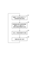
図6のフローチャートを参照して、映像表示装置1の動作について説明する。図6のフローチャートは、映像表示装置1の電源がオンされる等して表示部102a,102bへの映像表示を開始させるときにS1から実行される。S1で物体位置算出部108は、映像データ100Dに係る表示物体107a,107bを、使用者がその眼2a,2bで見た場合の仮想物体位置Zを算出する。
The operation of the image display device 1 will be described with reference to the flowchart of FIG. The flowchart of FIG. 6 is executed from S1 when image display on the
S2で視度変更指示部106は、視度変更駆動部104,104bが行う視度変更動作に関して、適切な動作指示情報を算出する。その際にはS1で算出された仮想物体位置Zの情報と、使用者情報記録部109および動作モード記録部110にそれぞれ記録されている使用者情報、動作モードの情報が使用される。
In S2, the visibility
S2で使用される使用者情報は、例えば図5に示すような使用者に関する物体距離と視度との関係に基づく情報である。視度変更指示部106は使用者に関する物体距離と視度との関係に基づいて、視度変更駆動部104a,104bが行う視度変更動作の指示情報を算出する。
The user information used in S2 is, for example, information based on the relationship between the object distance and diopter for the user as shown in FIG. The diopter
図7は、視度変更指示部106が算出する、仮想物体位置Z(縦軸)と映像表示装置1の視度(横軸)との関係を示すグラフである。例えば図5の線(A)で示す特性を有する第1の使用者を想定する。この場合、図7の線(D)で示す特性となるように、視度変更駆動部104a,104bへの動作指示が行われる。また図5の線(B)、線(C)で示す特性を有する第2、第3の使用者の場合にはそれぞれ、図7の線(E)、線(F)で示す特性となるように、視度変更駆動部104a,104bへの動作指示が行われる。従って、第1の使用者の場合に比べて、第2の使用者の場合、映像表示装置1の視度変更範囲が狭くなる。また、第1の使用者の場合に比べて、第3の使用者の場合、映像表示装置1の視度変更範囲は同じであるが、仮想物体位置Zが同じである場合の視度が異なる。このように使用者に応じた視度変更動作が行われることによって、使用者ごとに物体距離に対する視度の変化量が異なっていたとしても、使用者の違いによらず適切な視度での鮮明な表示が可能となる。
FIG. 7 is a graph showing the relationship between the virtual object position Z (vertical axis) and the visibility (horizontal axis) of the image display device 1 calculated by the visibility
また、図6のS2で使用される動作モードの情報は、動作モード記録部110に記録された動作モードの情報である。S2では、仮想物体位置Zや使用者情報に基づいて算出された視度となるように、視度変更駆動部104a,104bの駆動時の速度が動作モードに応じて変更される。動作モード記録部110に記録された動作モードが通常モードである場合、視度変更駆動部104a,104bは駆動可能な最大の速度で視度を変更する。一方、動作モード記録部110に記録された動作モードが省電力モードである場合、視度変更駆動部104a,104bは通常モードの場合の駆動速度よりも遅い速度で視度を変更する。視度変更の駆動速度が小さいと、視度の合わないタイミングが発生し、表示に違和感が生じる可能性がある。表示の違和感を抑制するためには、視度変更の駆動速度を極力大きくすることが望ましい。一方で、視度変更の駆動速度を大きくするためには、レンズ103a,103bを高速で駆動する必要があるので、より多くの電力を必要とする。従って、通常モードの場合には、できる限り表示の違和感を抑制するために、より大きな駆動速度で視度変更が行われる。また省電力モードの場合、多少の表示の違和感については許容し、消費電力がより少ない、通常モード時よりも小さい駆動速度で視度変更が行われる。すなわち動作モードに応じて視度変更の駆動時間を調整する制御が可能である。このような構成によって、映像表示装置1の使用状態に合わせて適切な駆動を実現することができる。
The operational mode information used in S2 of FIG. 6 is the operational mode information recorded in the operational
本実施形態では、使用者情報と動作モードの両方を用いて、適切な視度変更の動作制御を行う構成を示した。これに限らず、使用者情報または動作モードに基づいて適切な視度変更の動作制御を行う構成でもよい。例えば、使用者情報に基づいて視度変更の駆動速度を変更してもよく、視度変更範囲が狭い場合のほうが視度変更範囲が広い場合よりも視度変更の駆動速度を遅くしてもよい。また、使用者情報および動作モード以外の情報に基づいて、仮想物体位置Zに対する視度変更の動作制御を行う構成にしてもよい。 In this embodiment, a configuration is shown in which both user information and an operation mode are used to appropriately control the operation of changing the diopter. The configuration is not limited to this, and the configuration may be such that operation control for appropriately changing the dioptric power is performed based on the user information or the operation mode. For example, the driving speed for changing the diopter may be changed based on the user information, and the driving speed for changing the diopter may be slower when the diopter change range is narrower than when the diopter change range is wide. good. Further, the configuration may be such that the operation control for changing the dioptric power with respect to the virtual object position Z is performed based on information other than the user information and the operation mode.
図6のS3では、視度変更指示部106がS2で決定した視度変更動作を、視度変更駆動部104a,104bにそれぞれ指示し、視度変更駆動部104a,104bが動作する。レンズ103a,103bの駆動により、映像表示装置1の視度変更が行われる。次にS4で表示部102a,102bは、表示処理部101の指示に従って、映像データ100Dに対応する映像を表示する。
In S3 of FIG. 6, the visibility
本実施形態においては、S3で実施した視度変更動作の後に、S4で表示部102a,102bの表示処理が行われる構成である。これに限定されず、S3およびS4の処理を同時に行う構成や、S3の前にS4の処理を実行する構成でもよい。
In this embodiment, the display processing of the
以上に示した構成によって、使用者の相違や動作モード等の、映像表示装置1の使用状態に応じて、仮想物体位置Zに基づく視度変更動作を適切に行うことができる。使用者ごとに異なる物体距離と視度との関係等の個人差や、映像表示装置1の動作モードの相違等、映像表示装置1の使用状態の如何に関わらず、適切な視度変更動作を実現できる。本実施形態によれば、使用者が異なる場合でも仮想物体位置Zに関わらず鮮明な表示が可能であり、使用状態によっては映像表示装置1を長時間にわたって使用することが可能となる。なお、映像表示装置1の使用状態の情報である使用者の情報等については、使用するたびに使用者または外部装置によって入力されるようにしてもよい。 With the configuration described above, it is possible to appropriately perform the dioptric power changing operation based on the virtual object position Z according to the usage state of the image display device 1 such as the difference in users and the operation mode. Appropriate diopter changing operation is performed regardless of the usage state of the image display device 1, such as individual differences such as the relationship between the object distance and the diopter that differ for each user, and differences in the operation modes of the image display device 1. realizable. According to this embodiment, even if the user is different, a clear display is possible regardless of the virtual object position Z, and the image display device 1 can be used for a long time depending on the usage condition. User information, which is information on the state of use of the image display device 1, may be input by the user or an external device each time the device is used.
以上、本発明の好ましい実施形態について説明したが、本発明は前記実施形態に限定されず、その要旨の範囲内で種々の変形および変更が可能である。 Although preferred embodiments of the present invention have been described above, the present invention is not limited to the above embodiments, and various modifications and changes are possible within the scope of the gist of the present invention.
(その他の実施形態)
本発明は、上述の実施形態の1以上の機能を実現するプログラムを、ネットワーク又は記憶媒体を介してシステム又は装置に供給し、そのシステム又は装置のコンピュータにおける1つ以上のプロセッサがプログラムを読出し実行する処理でも実現可能である。また、1以上の機能を実現する回路(例えば、ASIC)によっても実現可能である。
(Other embodiments)
The present invention supplies a program that implements one or more functions of the above-described embodiments to a system or apparatus via a network or a storage medium, and one or more processors in the computer of the system or apparatus reads and executes the program. It can also be realized by processing to It can also be implemented by a circuit (for example, ASIC) that implements one or more functions.
1 映像表示装置
101 表示処理部
102a,102b 表示部
103a,103b レンズ
104a,104b 視度変更駆動部
106 視度変更指示部
108 物体位置算出部
109 使用者情報記録部
110 動作モード記録部
1
Claims (10)
前記第1および第2の表示光学系による映像における表示物体の物体位置を算出する算出手段と、
前記物体位置および前記映像表示装置の使用状態の情報に基づいて前記第1および第2の表示光学系に係る視度の変更を行う視度変更手段と、を備える
ことを特徴とする映像表示装置。 An image display device comprising first and second display optical systems for displaying images respectively to the left eye and right eye of a user,
a calculating means for calculating an object position of a display object in the images by the first and second display optical systems;
and a dioptric power changing means for changing the dioptric power of the first and second display optical systems based on information on the position of the object and the state of use of the video display apparatus. .
ことを特徴とする請求項1に記載の映像表示装置。 2. The image display device according to claim 1, further comprising recording means for recording information on the state of use.
ことを特徴とする請求項2に記載の映像表示装置。 3. The video display device according to claim 2, wherein said recording means records information on a user or information on an operation mode of said video display device as said usage state information.
前記第1および第2の表示光学系を構成する光学部材または表示部を移動させることが可能な駆動手段と、
前記駆動手段の駆動を指示する指示手段と、を備え、
前記指示手段は、前記使用状態の情報から前記物体位置に対する視度の変更量を決定し、前記変更量に対応する指示を前記駆動手段に行う
ことを特徴とする請求項2または請求項3に記載の映像表示装置。 The dioptric power changing means is
driving means capable of moving optical members or display units constituting the first and second display optical systems;
and an instruction means for instructing the driving of the driving means,
4. The apparatus according to claim 2, wherein the instruction means determines a change amount of dioptric power with respect to the object position from the information on the state of use, and issues an instruction corresponding to the change amount to the drive means. The video display device described.
前記視度変更手段は、前記記録手段から取得される前記使用者に関する情報を用いて前記変更量を決定する
ことを特徴とする請求項4に記載の映像表示装置。 The recording means records, as the information on the user, information on the amount of change in dioptric power with respect to an object distance,
5. The image display apparatus according to claim 4, wherein said dioptric power changing means determines said change amount using information about said user acquired from said recording means.
前記視度変更手段は、前記記録手段から取得される前記動作モードの情報を用いて、前記物体位置に対する視度を変更する時間を調整する
ことを特徴とする請求項4に記載の映像表示装置。 The recording means records information on the operation mode of the image display device,
5. The image display device according to claim 4, wherein the dioptric power changing unit adjusts the time for changing the dioptric power with respect to the object position using the information of the operation mode acquired from the recording unit. .
前記視度変更手段は、前記第1のモードにて第1の速度で視度の変更が可能であり、前記第2のモードにて前記第1の速度よりも遅い第2の速度で視度の変更が可能である
ことを特徴とする請求項6に記載の映像表示装置。 The operation mode is a first mode and a second mode in which power consumption is suppressed more than the first mode,
The diopter changing means is capable of changing the diopter at a first speed in the first mode, and changing the diopter at a second speed slower than the first speed in the second mode. 7. The image display device according to claim 6, wherein the change of is possible.
ことを特徴とする請求項1乃至7のいずれか1項に記載の映像表示装置。 The image display device according to any one of claims 1 to 7, wherein the first and second display optical systems display images having parallax.
前記第1および第2の表示光学系による映像における表示物体の物体位置を算出する工程と、
前記物体位置の情報および前記映像表示装置の使用状態の情報に基づいて前記第1および第2の表示光学系に係る視度の変更を行う工程と、を有する
ことを特徴とする映像表示装置の制御方法。 A control method executed by an image display device having first and second display optical systems for displaying images to the left eye and right eye of a user, respectively, comprising:
a step of calculating an object position of a display object in images by the first and second display optical systems;
and changing the dioptric power of the first and second display optical systems based on the information on the position of the object and the information on the state of use of the image display device. control method.
ことを特徴とするプログラム。
A program that causes a computer of a video display device to execute each step according to claim 9 .
Priority Applications (3)
| Application Number | Priority Date | Filing Date | Title |
|---|---|---|---|
| JP2021138310A JP2023032278A (en) | 2021-08-26 | 2021-08-26 | Video display device and method for controlling the same, and program |
| US17/885,653 US11740478B2 (en) | 2021-08-26 | 2022-08-11 | Display device, control method thereof, and recording medium |
| CN202211025907.4A CN115728958A (en) | 2021-08-26 | 2022-08-25 | Display device, control method thereof, and recording medium |
Applications Claiming Priority (1)
| Application Number | Priority Date | Filing Date | Title |
|---|---|---|---|
| JP2021138310A JP2023032278A (en) | 2021-08-26 | 2021-08-26 | Video display device and method for controlling the same, and program |
Publications (1)
| Publication Number | Publication Date |
|---|---|
| JP2023032278A true JP2023032278A (en) | 2023-03-09 |
Family
ID=85287188
Family Applications (1)
| Application Number | Title | Priority Date | Filing Date |
|---|---|---|---|
| JP2021138310A Pending JP2023032278A (en) | 2021-08-26 | 2021-08-26 | Video display device and method for controlling the same, and program |
Country Status (3)
| Country | Link |
|---|---|
| US (1) | US11740478B2 (en) |
| JP (1) | JP2023032278A (en) |
| CN (1) | CN115728958A (en) |
Family Cites Families (10)
| Publication number | Priority date | Publication date | Assignee | Title |
|---|---|---|---|---|
| JP2762677B2 (en) * | 1990-04-24 | 1998-06-04 | ソニー株式会社 | Optical device |
| US5737012A (en) * | 1994-12-01 | 1998-04-07 | Olympus Optical Co., Ltd. | Head mounted image display apparatus and image forming apparatus related thereto |
| JP2006195084A (en) | 2005-01-12 | 2006-07-27 | Sharp Corp | Display apparatus |
| US7828439B2 (en) * | 2008-01-21 | 2010-11-09 | Krall Jeffrey P | System and method for measuring fixation disparity and proprioceptive misalignment of the visual system |
| US7693256B2 (en) * | 2008-03-19 | 2010-04-06 | C-Rad Innovation Ab | Phase-contrast X-ray imaging |
| US8446676B2 (en) * | 2010-09-16 | 2013-05-21 | Olympus Corporation | Head-mounted display device |
| TWI531817B (en) * | 2014-01-16 | 2016-05-01 | 中強光電股份有限公司 | Virtual image display module and optical lens |
| US11138793B2 (en) * | 2014-03-14 | 2021-10-05 | Magic Leap, Inc. | Multi-depth plane display system with reduced switching between depth planes |
| US10445860B2 (en) * | 2015-12-08 | 2019-10-15 | Facebook Technologies, Llc | Autofocus virtual reality headset |
| US11137610B1 (en) * | 2020-12-24 | 2021-10-05 | Raytrx, Llc | System, method, and non-transitory computer-readable storage media related wearable pupil-forming display apparatus with variable opacity and dynamic focal length adjustment |
-
2021
- 2021-08-26 JP JP2021138310A patent/JP2023032278A/en active Pending
-
2022
- 2022-08-11 US US17/885,653 patent/US11740478B2/en active Active
- 2022-08-25 CN CN202211025907.4A patent/CN115728958A/en active Pending
Also Published As
| Publication number | Publication date |
|---|---|
| CN115728958A (en) | 2023-03-03 |
| US20230068868A1 (en) | 2023-03-02 |
| US11740478B2 (en) | 2023-08-29 |
Similar Documents
| Publication | Publication Date | Title |
|---|---|---|
| US11132056B2 (en) | Predictive eye tracking systems and methods for foveated rendering for electronic displays | |
| JP5967597B2 (en) | Image display device and image display method | |
| US10871825B1 (en) | Predictive eye tracking systems and methods for variable focus electronic displays | |
| US10241329B2 (en) | Varifocal aberration compensation for near-eye displays | |
| JP6507241B2 (en) | Head-mounted display device and vision assistance method using the same | |
| JP6339239B2 (en) | Head-mounted display device and video display system | |
| JP3802630B2 (en) | Stereoscopic image generating apparatus and stereoscopic image generating method | |
| JP6378781B2 (en) | Head-mounted display device and video display system | |
| WO2020123561A1 (en) | Adaptive viewports for hypervocal viewport (hvp) displays | |
| JPH03292093A (en) | Three-dimensional display device | |
| JPWO2016021034A1 (en) | 3D gaze point location algorithm | |
| US11300805B2 (en) | Stereoscopic eyeglasses, method for designing eyeglass lens to be used for the stereoscopic eyeglasses, and method for observing stereoscopic image | |
| EP3871033B1 (en) | Fresnel-based varifocal lens assembly for vr or ar displays | |
| US11221487B2 (en) | Method and device of field sequential imaging for large field of view augmented/virtual reality | |
| CN111580273A (en) | Video transmission type head-mounted display and control method thereof | |
| GB2595909A (en) | Gaze tracking apparatus and systems | |
| JP2023032278A (en) | Video display device and method for controlling the same, and program | |
| JPH0756517A (en) | Spectacle type image display device | |
| US20210176454A1 (en) | Video Engine for Generating an Enhanced Impression of Depth Based Upon Two-Dimensioned Video Content | |
| CN117998071A (en) | Eye movement tracking light field 3D display method and device, electronic equipment and storage medium |