JP2022534320A - Context Determination for Matrix-Based Intra Prediction - Google Patents
Context Determination for Matrix-Based Intra Prediction Download PDFInfo
- Publication number
- JP2022534320A JP2022534320A JP2021571532A JP2021571532A JP2022534320A JP 2022534320 A JP2022534320 A JP 2022534320A JP 2021571532 A JP2021571532 A JP 2021571532A JP 2021571532 A JP2021571532 A JP 2021571532A JP 2022534320 A JP2022534320 A JP 2022534320A
- Authority
- JP
- Japan
- Prior art keywords
- mode
- video block
- block
- current
- video
- Prior art date
- Legal status (The legal status is an assumption and is not a legal conclusion. Google has not performed a legal analysis and makes no representation as to the accuracy of the status listed.)
- Pending
Links
- 238000000034 method Methods 0.000 claims abstract description 286
- 241000023320 Luma <angiosperm> Species 0.000 claims abstract description 99
- OSWPMRLSEDHDFF-UHFFFAOYSA-N methyl salicylate Chemical compound COC(=O)C1=CC=CC=C1O OSWPMRLSEDHDFF-UHFFFAOYSA-N 0.000 claims abstract description 98
- 239000011159 matrix material Substances 0.000 claims abstract description 56
- 238000012545 processing Methods 0.000 claims abstract description 54
- 238000006243 chemical reaction Methods 0.000 claims abstract description 32
- 239000013598 vector Substances 0.000 claims description 62
- 230000011664 signaling Effects 0.000 claims description 20
- 230000004044 response Effects 0.000 claims description 18
- 238000004590 computer program Methods 0.000 claims description 11
- 230000015654 memory Effects 0.000 claims description 9
- 238000005070 sampling Methods 0.000 claims description 2
- 238000001914 filtration Methods 0.000 description 67
- 230000008569 process Effects 0.000 description 50
- PXFBZOLANLWPMH-UHFFFAOYSA-N 16-Epiaffinine Natural products C1C(C2=CC=CC=C2N2)=C2C(=O)CC2C(=CC)CN(C)C1C2CO PXFBZOLANLWPMH-UHFFFAOYSA-N 0.000 description 23
- 238000005516 engineering process Methods 0.000 description 22
- 238000005192 partition Methods 0.000 description 12
- 238000013139 quantization Methods 0.000 description 11
- 238000009795 derivation Methods 0.000 description 10
- 238000010586 diagram Methods 0.000 description 9
- 238000010276 construction Methods 0.000 description 8
- 238000012935 Averaging Methods 0.000 description 7
- 230000006835 compression Effects 0.000 description 6
- 238000007906 compression Methods 0.000 description 6
- 238000012360 testing method Methods 0.000 description 6
- 208000037170 Delayed Emergence from Anesthesia Diseases 0.000 description 3
- 230000003044 adaptive effect Effects 0.000 description 3
- 238000007792 addition Methods 0.000 description 3
- 238000004891 communication Methods 0.000 description 3
- 238000013507 mapping Methods 0.000 description 3
- 230000009466 transformation Effects 0.000 description 3
- FZEIVUHEODGHML-UHFFFAOYSA-N 2-phenyl-3,6-dimethylmorpholine Chemical compound O1C(C)CNC(C)C1C1=CC=CC=C1 FZEIVUHEODGHML-UHFFFAOYSA-N 0.000 description 2
- 101100129500 Caenorhabditis elegans max-2 gene Proteins 0.000 description 2
- 230000008901 benefit Effects 0.000 description 2
- 238000004422 calculation algorithm Methods 0.000 description 2
- 230000006837 decompression Effects 0.000 description 2
- 230000001419 dependent effect Effects 0.000 description 2
- 238000013461 design Methods 0.000 description 2
- 238000006073 displacement reaction Methods 0.000 description 2
- 230000003993 interaction Effects 0.000 description 2
- 230000003287 optical effect Effects 0.000 description 2
- 230000002093 peripheral effect Effects 0.000 description 2
- 238000003672 processing method Methods 0.000 description 2
- 238000013515 script Methods 0.000 description 2
- 238000000926 separation method Methods 0.000 description 2
- 238000013519 translation Methods 0.000 description 2
- 230000000007 visual effect Effects 0.000 description 2
- QEDQZYNGDXULGO-UHFFFAOYSA-N 3-methyl-2-(3-methylphenyl)morpholine Chemical compound CC1NCCOC1C1=CC=CC(C)=C1 QEDQZYNGDXULGO-UHFFFAOYSA-N 0.000 description 1
- 238000003491 array Methods 0.000 description 1
- 230000003190 augmentative effect Effects 0.000 description 1
- 230000003796 beauty Effects 0.000 description 1
- 230000000903 blocking effect Effects 0.000 description 1
- 238000004364 calculation method Methods 0.000 description 1
- 230000001413 cellular effect Effects 0.000 description 1
- 230000008859 change Effects 0.000 description 1
- OVBPIULPVIDEAO-LBPRGKRZSA-N folic acid Chemical compound C=1N=C2NC(N)=NC(=O)C2=NC=1CNC1=CC=C(C(=O)N[C@@H](CCC(O)=O)C(O)=O)C=C1 OVBPIULPVIDEAO-LBPRGKRZSA-N 0.000 description 1
- 230000006870 function Effects 0.000 description 1
- 230000007274 generation of a signal involved in cell-cell signaling Effects 0.000 description 1
- 238000012986 modification Methods 0.000 description 1
- 230000004048 modification Effects 0.000 description 1
- 238000004321 preservation Methods 0.000 description 1
- 230000000644 propagated effect Effects 0.000 description 1
- 238000013138 pruning Methods 0.000 description 1
- 238000011946 reduction process Methods 0.000 description 1
- 239000004065 semiconductor Substances 0.000 description 1
- 238000000638 solvent extraction Methods 0.000 description 1
- 230000002123 temporal effect Effects 0.000 description 1
- 230000001131 transforming effect Effects 0.000 description 1
Images


Classifications
-
- H—ELECTRICITY
- H04—ELECTRIC COMMUNICATION TECHNIQUE
- H04N—PICTORIAL COMMUNICATION, e.g. TELEVISION
- H04N19/00—Methods or arrangements for coding, decoding, compressing or decompressing digital video signals
- H04N19/10—Methods or arrangements for coding, decoding, compressing or decompressing digital video signals using adaptive coding
- H04N19/102—Methods or arrangements for coding, decoding, compressing or decompressing digital video signals using adaptive coding characterised by the element, parameter or selection affected or controlled by the adaptive coding
- H04N19/103—Selection of coding mode or of prediction mode
- H04N19/11—Selection of coding mode or of prediction mode among a plurality of spatial predictive coding modes
-
- H—ELECTRICITY
- H04—ELECTRIC COMMUNICATION TECHNIQUE
- H04N—PICTORIAL COMMUNICATION, e.g. TELEVISION
- H04N19/00—Methods or arrangements for coding, decoding, compressing or decompressing digital video signals
- H04N19/10—Methods or arrangements for coding, decoding, compressing or decompressing digital video signals using adaptive coding
- H04N19/102—Methods or arrangements for coding, decoding, compressing or decompressing digital video signals using adaptive coding characterised by the element, parameter or selection affected or controlled by the adaptive coding
- H04N19/103—Selection of coding mode or of prediction mode
- H04N19/105—Selection of the reference unit for prediction within a chosen coding or prediction mode, e.g. adaptive choice of position and number of pixels used for prediction
-
- H—ELECTRICITY
- H04—ELECTRIC COMMUNICATION TECHNIQUE
- H04N—PICTORIAL COMMUNICATION, e.g. TELEVISION
- H04N19/00—Methods or arrangements for coding, decoding, compressing or decompressing digital video signals
- H04N19/10—Methods or arrangements for coding, decoding, compressing or decompressing digital video signals using adaptive coding
- H04N19/102—Methods or arrangements for coding, decoding, compressing or decompressing digital video signals using adaptive coding characterised by the element, parameter or selection affected or controlled by the adaptive coding
- H04N19/119—Adaptive subdivision aspects, e.g. subdivision of a picture into rectangular or non-rectangular coding blocks
-
- H—ELECTRICITY
- H04—ELECTRIC COMMUNICATION TECHNIQUE
- H04N—PICTORIAL COMMUNICATION, e.g. TELEVISION
- H04N19/00—Methods or arrangements for coding, decoding, compressing or decompressing digital video signals
- H04N19/10—Methods or arrangements for coding, decoding, compressing or decompressing digital video signals using adaptive coding
- H04N19/102—Methods or arrangements for coding, decoding, compressing or decompressing digital video signals using adaptive coding characterised by the element, parameter or selection affected or controlled by the adaptive coding
- H04N19/132—Sampling, masking or truncation of coding units, e.g. adaptive resampling, frame skipping, frame interpolation or high-frequency transform coefficient masking
-
- H—ELECTRICITY
- H04—ELECTRIC COMMUNICATION TECHNIQUE
- H04N—PICTORIAL COMMUNICATION, e.g. TELEVISION
- H04N19/00—Methods or arrangements for coding, decoding, compressing or decompressing digital video signals
- H04N19/10—Methods or arrangements for coding, decoding, compressing or decompressing digital video signals using adaptive coding
- H04N19/134—Methods or arrangements for coding, decoding, compressing or decompressing digital video signals using adaptive coding characterised by the element, parameter or criterion affecting or controlling the adaptive coding
- H04N19/157—Assigned coding mode, i.e. the coding mode being predefined or preselected to be further used for selection of another element or parameter
- H04N19/159—Prediction type, e.g. intra-frame, inter-frame or bidirectional frame prediction
-
- H—ELECTRICITY
- H04—ELECTRIC COMMUNICATION TECHNIQUE
- H04N—PICTORIAL COMMUNICATION, e.g. TELEVISION
- H04N19/00—Methods or arrangements for coding, decoding, compressing or decompressing digital video signals
- H04N19/10—Methods or arrangements for coding, decoding, compressing or decompressing digital video signals using adaptive coding
- H04N19/169—Methods or arrangements for coding, decoding, compressing or decompressing digital video signals using adaptive coding characterised by the coding unit, i.e. the structural portion or semantic portion of the video signal being the object or the subject of the adaptive coding
- H04N19/17—Methods or arrangements for coding, decoding, compressing or decompressing digital video signals using adaptive coding characterised by the coding unit, i.e. the structural portion or semantic portion of the video signal being the object or the subject of the adaptive coding the unit being an image region, e.g. an object
- H04N19/176—Methods or arrangements for coding, decoding, compressing or decompressing digital video signals using adaptive coding characterised by the coding unit, i.e. the structural portion or semantic portion of the video signal being the object or the subject of the adaptive coding the unit being an image region, e.g. an object the region being a block, e.g. a macroblock
-
- H—ELECTRICITY
- H04—ELECTRIC COMMUNICATION TECHNIQUE
- H04N—PICTORIAL COMMUNICATION, e.g. TELEVISION
- H04N19/00—Methods or arrangements for coding, decoding, compressing or decompressing digital video signals
- H04N19/10—Methods or arrangements for coding, decoding, compressing or decompressing digital video signals using adaptive coding
- H04N19/169—Methods or arrangements for coding, decoding, compressing or decompressing digital video signals using adaptive coding characterised by the coding unit, i.e. the structural portion or semantic portion of the video signal being the object or the subject of the adaptive coding
- H04N19/186—Methods or arrangements for coding, decoding, compressing or decompressing digital video signals using adaptive coding characterised by the coding unit, i.e. the structural portion or semantic portion of the video signal being the object or the subject of the adaptive coding the unit being a colour or a chrominance component
-
- H—ELECTRICITY
- H04—ELECTRIC COMMUNICATION TECHNIQUE
- H04N—PICTORIAL COMMUNICATION, e.g. TELEVISION
- H04N19/00—Methods or arrangements for coding, decoding, compressing or decompressing digital video signals
- H04N19/40—Methods or arrangements for coding, decoding, compressing or decompressing digital video signals using video transcoding, i.e. partial or full decoding of a coded input stream followed by re-encoding of the decoded output stream
-
- H—ELECTRICITY
- H04—ELECTRIC COMMUNICATION TECHNIQUE
- H04N—PICTORIAL COMMUNICATION, e.g. TELEVISION
- H04N19/00—Methods or arrangements for coding, decoding, compressing or decompressing digital video signals
- H04N19/50—Methods or arrangements for coding, decoding, compressing or decompressing digital video signals using predictive coding
- H04N19/59—Methods or arrangements for coding, decoding, compressing or decompressing digital video signals using predictive coding involving spatial sub-sampling or interpolation, e.g. alteration of picture size or resolution
-
- H—ELECTRICITY
- H04—ELECTRIC COMMUNICATION TECHNIQUE
- H04N—PICTORIAL COMMUNICATION, e.g. TELEVISION
- H04N19/00—Methods or arrangements for coding, decoding, compressing or decompressing digital video signals
- H04N19/50—Methods or arrangements for coding, decoding, compressing or decompressing digital video signals using predictive coding
- H04N19/593—Methods or arrangements for coding, decoding, compressing or decompressing digital video signals using predictive coding involving spatial prediction techniques
-
- H—ELECTRICITY
- H04—ELECTRIC COMMUNICATION TECHNIQUE
- H04N—PICTORIAL COMMUNICATION, e.g. TELEVISION
- H04N19/00—Methods or arrangements for coding, decoding, compressing or decompressing digital video signals
- H04N19/70—Methods or arrangements for coding, decoding, compressing or decompressing digital video signals characterised by syntax aspects related to video coding, e.g. related to compression standards
Landscapes
- Engineering & Computer Science (AREA)
- Multimedia (AREA)
- Signal Processing (AREA)
- Compression Or Coding Systems Of Tv Signals (AREA)
Abstract
ビデオコーディングのためのマトリクスベースイントラ予測方法を含む、デジタルビデオコーディングのためのデバイス、システム及び方法が、記載される。代表的な態様では、ビデオ処理のための方法は、ビデオのルーマビデオブロックがマトリクスベースイントラ予測(MIP)モードを用いてコーディングされるかどうかの第1決定を実行するステップと、ルーマビデオブロックが、ビデオの現在のクロマビデオブロックのためのクロマイントラモードを決定するために適用可能であるとの第2決定を実行するステップと、第1決定及び第2決定に基づき、現在のクロマビデオブロックに使用されるクロマイントラモードに関する第3決定を実行するステップと、第3決定に基づき、現在のクロマビデオブロックと現在のクロマビデオブロックのビットストリーム表現との間の変換を実行するステップとを含む。Devices, systems and methods for digital video coding are described, including matrix-based intra-prediction methods for video coding. In a representative aspect, a method for video processing comprises the steps of: performing a first determination whether a luma video block of a video is coded using a matrix-based intra-prediction (MIP) mode; , making a second determination that is applicable to determining a chroma intra mode for a current chroma video block of video; and based on the first determination and the second determination: making a third determination regarding the chroma intra mode to be used; and performing a conversion between the current chroma video block and a bitstream representation of the current chroma video block based on the third determination.
Description
[関連出願への相互参照]
適用可能な特許法及び/又はパリ条約に従う規則の下で、本願は、2019年6月5日に出願された国際特許出願第PCT/CN2019/090205号の優先権及び利益を適宜請求するよう行われる。法の下での全ての目的のために、上記の出願の全開示は、本願の開示の部分として参照により援用される。
[Cross reference to related application]
Under applicable patent law and/or regulations pursuant to the Paris Convention, this application is hereby made to claim priority and benefit of International Patent Application No. PCT/CN2019/090205 filed June 5, 2019. will be For all purposes under the law, the entire disclosure of the above application is incorporated by reference as part of the present disclosure.
[技術分野]
本特許文献は、ビデオコーディング技術、デバイス及びシステムに関係がある。
[Technical field]
This patent document relates to video coding techniques, devices and systems.
ビデオ圧縮の進歩にかかわらず、デジタルビデオは依然として、インターネット及び他のデジタル通信ネットワーク上での最大のバンド幅使用を占めている。ビデオを受信し表示することができるユーザデバイスの接続数が増えるにつれて、デジタルビデオ利用のためのバンド幅需要は増え続けることが予想される。 Despite advances in video compression, digital video still accounts for the largest bandwidth usage on the Internet and other digital communication networks. Bandwidth demand for digital video usage is expected to continue to grow as the number of user device connections capable of receiving and displaying video increases.
デジタルビデオコーディングに関連したデバイス、システム及び方法、具体的には、ビデオコーディングのためのマトリクスベースイントラ予測方法が、記載される。記載されている方法は、既存のビデオコーディング標準規格(例えば、High Efficiency Video Coding(HEVC))及び将来のビデオコーディング標準規格(例えば、Versatile Video Coding(VVC))又はコーデックに適用されてもよい。 Devices, systems and methods related to digital video coding and, in particular, matrix-based intra-prediction methods for video coding are described. The methods described may be applied to existing video coding standards (eg, High Efficiency Video Coding (HEVC)) and future video coding standards (eg, Versatile Video Coding (VVC)) or codecs.
1つの代表的な態様で、開示されている技術は、ビデオ処理のための方法を提供するために使用され得る。例示的な方法は、ビデオのルーマビデオブロックが、該ルーマビデオブロックの予測ブロックが、前記ビデオの前にコーディングされたサンプルに対して、マトリクスベクトル乗算演算が後に続き、選択的にアップサンプリング動作が後に続く境界ダウンサンプリング動作を実行することによって決定されるマトリクスベースイントラ予測(Matrix-based Intra Prediction,MIP)モードを用いてコーディングされるかどうかの第1決定を実行するステップと、前記ルーマビデオブロックが、前記ビデオの現在のクロマビデオブロックのためのクロマイントラモードを決定するために適用可能であるとの第2決定を実行するステップであり、前記第2決定の実行は、前記現在のクロマビデオブロックに関連した現在のピクチャの左上ルーマサンプルに対する前記現在のクロマビデオブロックの左上サンプルに基づき、前記第2決定の実行は、現在のビデオユニットのカラーフォーマット及び/又は前記ルーマビデオブロックに対する前記現在のクロマビデオブロックの大きさに基づく、ステップと、前記第1決定及び前記第2決定に基づき、前記現在のクロマビデオブロックに使用される前記クロマイントラモードに関する第3決定を実行するステップと、前記第3決定に基づき、前記現在のクロマビデオブロックと該現在のクロマビデオブロックのビットストリーム表現との間の変換を実行するステップとを含む。 In one exemplary aspect, the disclosed technology can be used to provide a method for video processing. An exemplary method includes a luma video block of a video in which a predictive block of the luma video block is a matrix-vector multiplication operation followed by an optional upsampling operation on previously coded samples of the video. performing a first determination whether the luma video block is coded using a Matrix-based Intra Prediction (MIP) mode determined by performing a subsequent boundary downsampling operation; is applicable to determine a chroma intra mode for a current chroma video block of said video, said performing said second determining comprises: performing said current chroma video Based on the top left sample of the current chroma video block relative to the top left luma sample of the current picture associated with the block, performing the second determination includes: color format of the current video unit and/or the current video block for the luma video block. based on the size of a chroma video block; making a third decision regarding the chroma intra mode to be used for the current chroma video block based on the first decision and the second decision; 3, based on the determination, performing a conversion between the current chroma video block and a bitstream representation of the current chroma video block.
他の代表的な態様では、開示されている技術は、ビデオ処理のための方法を提供するために使用され得る。例示的な方法は、ビデオのルーマビデオブロックが、該ルーマビデオブロックの予測ブロックが、前記ビデオの前にコーディングされたサンプルに対して、マトリクスベクトル乗算演算が後に続き、選択的にアップサンプリング動作が後に続く境界ダウンサンプリング動作を実行することによって決定されるマトリクスベースイントラ予測(MIP)モードを用いてコーディングされるとの第1決定を実行するステップと、前記第1決定に基づき、導出モード(Derived Mode,DM)が、前記ルーマビデオブロックに関連した現在のクロマビデオブロックのためのクロマイントラモードとして使用されるかどうかに関して、規則に従って、第2決定を実行するステップと、前記第2決定に基づき、前記現在のクロマビデオブロックと該現在のクロマビデオブロックのビットストリーム表現との間の変換を実行するステップとを含む。 In other exemplary aspects, the disclosed techniques can be used to provide a method for video processing. An exemplary method includes a luma video block of a video in which a predictive block of the luma video block is a matrix-vector multiplication operation followed by an optional upsampling operation on previously coded samples of the video. performing a first determination to be coded using a matrix-based intra-prediction (MIP) mode determined by performing a subsequent boundary downsampling operation; Mode, DM) is used as a chroma intra mode for a current chroma video block associated with said luma video block, making a second determination according to a rule; , performing a conversion between the current chroma video block and a bitstream representation of the current chroma video block.
他の代表的な態様では、開示されている技術は、ビデオ処理のための方法を提供するために使用され得る。例示的な方法は、ビデオの現在のビデオブロックが、該現在のビデオブロックの予測ブロックが、前記ビデオの前にコーディングされたサンプルに対して、マトリクスベクトル乗算演算が後に続き、選択的にアップサンプリング動作が後に続く境界ダウンサンプリング動作を実行することによって決定されるマトリクスベースイントラ予測(MIP)モードでコーディングされることを決定するステップと、前記決定するステップに基づき、規則に基づいて最確モード(Most Probable Mode,MPM)リストを生成するステップであり、前記規則は、前記MPMリストが、前記現在のビデオブロックの隣接ビデオブロックについて生成された他のMPMリストから独立して生成されることを定める、前記生成するステップと、前記MPMリストを用いて前記現在のビデオブロックと該現在のビデオブロックのビットストリーム表現との間の変換を実行するステップとを含む。 In other exemplary aspects, the disclosed techniques can be used to provide a method for video processing. An exemplary method selectively upsamples a current video block of a video, a prediction block of the current video block, on previously coded samples of the video, followed by a matrix-vector multiplication operation. determining that the operation is coded in a matrix-based intra-prediction (MIP) mode determined by performing a subsequent boundary downsampling operation; generating a Most Probable Mode (MPM) list, wherein said rule stipulates that said MPM list is generated independently from other MPM lists generated for neighboring video blocks of said current video block. , the generating and performing a conversion between the current video block and a bitstream representation of the current video block using the MPM list.
他の代表的な態様では、開示されている技術は、ビデオ処理のための方法を提供するために使用され得る。例示的な方法は、ビデオの現在のビデオブロックの予測ブロックが、前記ビデオの前にコーディングされたサンプルに対して、マトリクスベクトル乗算演算が後に続き、選択的にアップサンプリング動作が後に続く境界ダウンサンプリング動作を実行することによって決定されるマトリクスベースイントラ予測(MIP)モードを用いて、前記現在のビデオブロックをエンコードするステップであり、規則が、前記MIPモードで使用されるマトリクスの数と前記現在のビデオブロックの大きさとの間の関係を記述する、ステップと、前記現在のビデオブロックのエンコードされた表現を前記現在のビデオブロックのビットストリーム表現に加えるステップとを含む。 In other exemplary aspects, the disclosed techniques can be used to provide a method for video processing. An exemplary method is that a prediction block of a current video block of a video is boundary downsampled followed by a matrix-vector multiplication operation, optionally followed by an upsampling operation, on previously coded samples of said video. encoding the current video block using a matrix-based intra-prediction (MIP) mode determined by performing an operation, wherein a rule determines the number of matrices used in the MIP mode and the current describing a relationship between sizes of video blocks; and adding an encoded representation of the current video block to a bitstream representation of the current video block.
他の代表的な態様では、開示されている技術は、ビデオ処理のための方法を提供するために使用され得る。例示的な方法は、ビデオの現在のビデオブロックが、前記ビデオの前にコーディングされたサンプルに対して、マトリクスベクトル乗算演算が後に続き、選択的にアップサンプリング動作が後に続く境界ダウンサンプリング動作を実行することによって決定されるマトリクスベースイントラ予測(MIP)モードを用いて、前記現在のビデオブロックの予測ブロックがビットストリーム表現においてエンコードされていることを決定するステップであり、規則が、前記MIPモードで使用されるマトリクスの数と前記現在のビデオブロックの大きさとの間の関係を記述する、ステップと、前記ビットストリーム表現をパースしデコードすることによって、前記現在のビデオブロックのデコードされた表現を生成するステップとを含む。 In other exemplary aspects, the disclosed techniques can be used to provide a method for video processing. An exemplary method performs a boundary downsampling operation followed by a matrix-vector multiplication operation, optionally followed by an upsampling operation, on previously coded samples of said video for a current video block of a video. determining that a prediction block of said current video block is encoded in a bitstream representation using a matrix-based intra prediction (MIP) mode determined by: describing the relationship between the number of matrices used and the size of the current video block; and parsing and decoding the bitstream representation to generate a decoded representation of the current video block. and the step of
他の代表的な態様では、開示されている技術は、ビデオ処理のための方法を提供するために使用され得る。この例示的な方法は、アフィン線形重み付きイントラ予測(Affine Linear Weighted Intra Prediction,ALWIP)モードを用いて現在のビデオブロックがコーディングされていることを決定するステップと、該決定に基づき、非ALWIPイントラモードのための最確モード(MPM)リストの少なくとも一部に基づいて前記ALWIPモードのためのMPMリストの少なくとも一部を構成するステップと、前記ALWIPモードのための前記MPMリストに基づき、前記現在のビデオブロックと該現在のビデオブロックのビットストリーム表現との間の変換を実行するステップとを含む。 In other exemplary aspects, the disclosed techniques can be used to provide a method for video processing. This exemplary method comprises the steps of determining that a current video block is coded using an Affine Linear Weighted Intra Prediction (ALWIP) mode; configuring at least a portion of an MPM list for the ALWIP mode based at least in part on a most probable mode (MPM) list for the mode; and a bitstream representation of the current video block.
他の代表的な態様では、開示されている技術は、ビデオ処理のための方法を提供するために使用され得る。この例示的な方法は、現在のビデオブロックのルーマ成分がアフィン線形重み付きイントラ予測(ALWIP)モードを用いてコーディングされていることを決定するステップと、該決定に基づき、クロマイントラモードを推測するステップと、該クロマイントラモードに基づき、前記現在のビデオブロックと該現在のクロマビデオブロックのビットストリーム表現との間の変換を実行するステップとを含む。 In other exemplary aspects, the disclosed techniques can be used to provide a method for video processing. This exemplary method comprises the steps of determining that a luma component of a current video block is coded using an affine linear weighted intra prediction (ALWIP) mode, and inferring a chroma intra mode based on the determination. and performing a conversion between the current video block and a bitstream representation of the current chroma video block based on the chroma intra mode.
更なる他の代表的な態様では、開示されている技術は、ビデオ処理のための方法を提供するために使用され得る。この例示的な方法は、アフィン線形重み付きイントラ予測(ALWIP)モードを用いて現在のビデオブロックがコーディングされていることを決定するステップと、該決定に基づき、前記現在のビデオブロックと該現在のビデオブロックのビットストリーム表現との間の変換を実行するステップとを含む。 In yet another exemplary aspect, the disclosed techniques can be used to provide a method for video processing. This exemplary method comprises the steps of: determining that a current video block is coded using an affine linear weighted intra prediction (ALWIP) mode; and performing a conversion to and from a bitstream representation of the video block.
更なる他の代表的な態様では、開示されている技術は、ビデオ処理のための方法を提供するために使用され得る。この例示的な方法は、アフィン線形重み付きイントラ予測(ALWIP)モードとは異なったコーディングモードを用いて現在のビデオブロックがコーディングされていることを決定するステップと、該決定に基づき、前記現在のビデオブロックと該現在のクロマビデオブロックのビットストリーム表現との間の変換を実行するステップとを含む。 In yet another exemplary aspect, the disclosed techniques can be used to provide a method for video processing. This exemplary method comprises the steps of: determining that a current video block is coded using a coding mode different from an affine linear weighted intra prediction (ALWIP) mode; performing a conversion between a video block and a bitstream representation of the current chroma video block.
更なる他の代表的な態様では、開示されている技術は、ビデオ処理のための方法を提供するために使用され得る。この例示的な方法は、現在のビデオブロックについて、アフィン線形重み付きイントラ予測(ALWIP)モードを用いて第1予測を生成するステップと、該第1予測に基づき、ポジション依存イントラ予測結合(Position Dependent intra Prediction Combination,PDPC)を用いて第2予測を生成するステップと、該第2予測に基づき、前記現在のビデオブロックと該現在のビデオブロックのビットストリーム表現との間の変換を実行するステップとを含む。 In yet another exemplary aspect, the disclosed techniques can be used to provide a method for video processing. This exemplary method comprises the steps of generating a first prediction using an affine linear weighted intra prediction (ALWIP) mode for a current video block; intra Prediction Combination, PDPC) to generate a second prediction, and performing a transform between the current video block and a bitstream representation of the current video block based on the second prediction; including.
更なる他の代表的な態様では、開示されている技術は、ビデオ処理のための方法を提供するために使用され得る。この例示的な方法は、アフィン線形重み付きイントラ予測(ALWIP)モードを用いて現在のビデオブロックがコーディングされていることを決定するステップと、前記ALWIPモードに基づき、前記現在のビデオブロックの複数のサブブロックを予測するステップと、該予測に基づき、前記現在のビデオブロックと該現在のビデオブロックのビットストリーム表現との間の変換を実行するステップとを含む。 In yet another exemplary aspect, the disclosed techniques can be used to provide a method for video processing. This exemplary method comprises the steps of determining that a current video block is coded using an affine linear weighted intra prediction (ALWIP) mode; predicting a sub-block; and performing a transform between the current video block and a bitstream representation of the current video block based on the prediction.
更なる他の代表的な態様では、ビデオ処理の方法が開示される。方法は、現在のビデオブロックのための規則に基づき、前記現在のビデオブロックと該現在のビデオブロックのビットストリーム表現との間の変換中に、アフィン線形重み付きイントラ予測(ALWIP)モードの使用を示すフラグのコンテキストを決定するステップと、前記ALWIPモードに基づき、前記現在のビデオブロックの複数のサブブロックを予測するステップと、該予測に基づき、前記現在のビデオブロックと該現在のクロマビデオブロックのビットストリーム表現との間の変換を実行するステップとを含む。 In yet another representative aspect, a method of video processing is disclosed. The method includes using an affine linear weighted intra prediction (ALWIP) mode during conversion between the current video block and a bitstream representation of the current video block based on rules for the current video block. predicting a plurality of sub-blocks of the current video block based on the ALWIP mode; and based on the predictions of the current video block and the current chroma video block. and performing a conversion to and from a bitstream representation.
更なる他の代表的な態様では、ビデオ処理の方法が開示される。方法は、アフィン線形重み付きイントラ予測(ALWIP)モードを用いて現在のビデオブロックがコーディングされていることを決定するステップと、前記現在のビデオブロックと該現在のクロマビデオブロックのビットストリーム表現との間の変換中に、前記ALWIPモードに関連したアップサンプリングプロセスでの前記現在のビデオブロックのサンプルに対する少なくとも2つのフィルタリング段を実行するステップとを含み、前記少なくとも2つのフィルタリング段のうちの第1フィルタリング段における前記サンプルの第1精度は、前記少なくとも2つのフィルタリング段のうちの第2フィルタリング段における前記サンプルの第2精度とは異なる。 In yet another representative aspect, a method of video processing is disclosed. A method comprises the steps of: determining that a current video block is coded using an affine linear weighted intra prediction (ALWIP) mode; and bitstream representations of said current video block and said current chroma video block. performing at least two stages of filtering on the samples of the current video block in an upsampling process associated with the ALWIP mode during conversion between A first precision of the samples in a stage is different than a second precision of the samples in a second one of the at least two filtering stages.
更なる他の態様では、ビデオ処理の方法が開示される。方法は、アフィン線形重み付きイントラ予測(ALWIP)モードを用いて現在のビデオブロックがコーディングされていることを決定するステップと、前記現在のビデオブロックと該現在のビデオブロックのビットストリーム表現との間の変換中に、前記ALWIPモードに関連したアップサンプリングプロセスでの前記現在のビデオブロックのサンプルに対する少なくとも2つのフィルタリング段を実行するステップとを含み、前記アップサンプリングプロセスは、垂直及び水平の両方のアップサンプリングが実行される場合に一定順序で実行される。 In yet another aspect, a method of video processing is disclosed. between determining that a current video block is coded using an affine linear weighted intra prediction (ALWIP) mode; and a bitstream representation of the current video block and the current video block. and performing at least two stages of filtering on the samples of the current video block in an upsampling process associated with the ALWIP mode, the upsampling process including both vertical and horizontal upsampling. When sampling is performed, it is performed in a fixed order.
更なる他の態様では、ビデオ処理の方法が開示される。方法は、アフィン線形重み付きイントラ予測(ALWIP)モードを用いて現在のビデオブロックがコーディングされていることを決定するステップと、前記現在のビデオブロックと該現在のビデオブロックのビットストリーム表現との間の変換中に、前記ALWIPモードに関連したアップサンプリングプロセスでの前記現在のビデオブロックのサンプルに対する少なくとも2つのフィルタリング段を実行するステップとを含み、前記変換は、前記アップサンプリングプロセスより前に転置動作を実行することを含む。 In yet another aspect, a method of video processing is disclosed. between determining that a current video block is coded using an affine linear weighted intra prediction (ALWIP) mode; and a bitstream representation of the current video block and the current video block. and performing at least two stages of filtering on the samples of the current video block in the upsampling process associated with the ALWIP mode during the transformation of the ALWIP mode, wherein the transformation comprises a transpose operation prior to the upsampling process. including running
更なる他の代表的な態様では、上記の方法は、プロセッサ実行可能なコードの形で具現され、コンピュータ可読プログラム媒体に記憶される。 In yet another exemplary aspect, the above method is embodied in processor-executable code stored on a computer-readable program medium.
更なる他の代表的な態様では、上記の方法を実行するよう構成されている又はそのように動作可能であるデバイスが開示される。デバイスは、この方法を実装するようプログラムされているプロセッサを含んでもよい。 In yet another exemplary aspect, a device configured or operable to perform the above method is disclosed. The device may include a processor programmed to implement the method.
更なる他の代表的な態様では、ビデオデコーダ装置が、本明細書で記載される方法を実装してもよい。 In yet another exemplary aspect, a video decoder apparatus may implement the methods described herein.
開示されている技術の上記及び他の態様及び特徴は、図面、明細書、及び特許請求の範囲で更に詳細に記載される。 These and other aspects and features of the disclosed technology are described in further detail in the drawings, specification, and claims.
より高い解像度のビデオに対する需要の高まりにより、ビデオコーディング方法及び技術は、最新の技術において遍在している。ビデオコーデックは、通常、デジタルビデオを圧縮又は圧縮解除する電子回路又はソフトウェアを含み、より高いコーディング効率をもたらすよう改善され続けている。ビデオコーデックは、圧縮されていないビデオを圧縮された形式へ変換し、あるいは、その逆も同様である。ビデオ品質と、ビデオを表すために使用されるデータの量(ビットレートによって決定される)と、符号化及び復号化アルゴリズムの複雑さと、データ損失及びエラーに対する敏感さと、編集の容易さと、ランダムアクセスと、エンド間遅延(レイテンシ)との間には、複雑な関係が存在している。圧縮された形式は、通常、標準のビデオ圧縮規格、例えば、High Efficiency Video Coding(HEVC)標準規格(H.265又はMPEG-H Part2としても知られている)、最終決定されるべきVersatile Video Coding(VVC)標準規格、あるいは、他の現在及び/又は将来のビデオコーディング標準規格に従う。 Due to the increasing demand for higher resolution video, video coding methods and techniques are ubiquitous in the state of the art. Video codecs typically include electronic circuitry or software that compresses or decompresses digital video, and are continually being improved to provide higher coding efficiency. A video codec converts uncompressed video into compressed form or vice versa. Video quality, amount of data used to represent the video (determined by bitrate), complexity of encoding and decoding algorithms, susceptibility to data loss and errors, ease of editing, random access and end-to-end delay (latency). Compressed formats are usually standard video compression standards, such as the High Efficiency Video Coding (HEVC) standard (also known as H.265 or MPEG-H Part 2), Versatile Video Coding to be finalized. (VVC) standard, or other current and/or future video coding standards.
開示されている技術の実施形態は、ランタイム性能を改善するよう既存のビデオコーディング標準規格(例えば、HEVC、H.265)及び将来の標準規格に適用されてもよい。セクション見出しは、記載の読みやすさを改善するために本明細書で使用されており、議論又は実施形態(及び/又は実装)を各々のセクションにのみ限定されるものでは決してない。 Embodiments of the disclosed techniques may be applied to existing video coding standards (eg, HEVC, H.265) and future standards to improve runtime performance. Section headings are used herein to improve readability of the description and are in no way intended to limit the discussion or embodiments (and/or implementations) solely to their respective sections.
1 HEVCに関する寸評
1.1 HEVC/H.265におけるイントラ予測
イントラ予測は、検討されているカラーチャネルにおいて前に再構成されたサンプルを用いて所与の変換ブロック(Transform Block,TB)のサンプルを生成することを含む。イントラ予測モードは、ルーマチャネル及びクロマチャネルについて別々にシグナリングされ。クロマチャネルイントラ予測モードは、任意に、「DM_CHROMA」モードによりルーマチャネルイントラ予測モードに依存する。イントラ予測モードは予測ブロック(Prediction Block,PB)レベルでシグナリングされるが、イントラ予測プロセスは、CUの残差四分木ヒエラルキに従って、TBレベルで適用され、それによって、1つのTBのコーディングがCU内の次のTBのコーディングに影響を及ぼすことを可能にするので、参照値として使用されるサンプルまでの距離が低減される。
1 A short comment on HEVC 1.1 HEVC/H. Intra Prediction in H.265 Intra prediction involves generating samples for a given Transform Block (TB) using previously reconstructed samples in the color channel under consideration. Intra-prediction modes are signaled separately for luma and chroma channels. The chroma channel intra-prediction mode optionally depends on the luma channel intra-prediction mode via the "DM_CHROMA" mode. Although the intra-prediction mode is signaled at the Prediction Block (PB) level, the intra-prediction process is applied at the TB level according to the CU's residual quadtree hierarchy, whereby one TB's coding is applied to the CU. The distance to the samples used as reference values is reduced, as it allows to influence the coding of the next TB in .
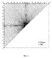
HEVCは、35個のイントラ予測モード、すなわち、DCモード、プレーナーモード(planer mode)、及び33個の指向性又は「角度」イントラ予測モードを含む。33個の角度イントラ予測モードは図1に表されている。 HEVC includes 35 intra-prediction modes: DC mode, planar mode, and 33 directional or "angular" intra-prediction modes. The 33 angular intra-prediction modes are represented in FIG.
クロマカラーチャネルに関連したPBについては、イントラ予測モードは、プレーナー、DC、水平、垂直、「DM_CHROMA」モード又は時々対角モード「34」のどれかとして指定される。 For PB associated with chroma color channels, the intra-prediction mode is specified as either planar, DC, horizontal, vertical, "DM_CHROMA" mode or sometimes diagonal mode "34".
4:2:2及び4:2:0のクロマフォーマットについては、クロマPBは、(夫々)2つ又は4つのルーマPBと重なり合う可能性があることに留意されたい。この場合に、DM_CHROMAのルーマ方向は、これらのルーマPBの左上から取られる。 Note that for 4:2:2 and 4:2:0 chroma formats, a chroma PB may overlap two or four luma PBs (respectively). In this case, the luma direction of DM_CHROMA is taken from the top left of these lumas PB.
DM_CHROMAモードは、ルーマカラーチャネルPBのイントラ予測モードがクロマカラーチャネルPBに適用されることを示す。これは比較的に一般的であるから、intra_chroma_pred_modeの最確モードコーディングスキームは、このモードが選択されることを優先してバイアスされる。 The DM_CHROMA mode indicates that the intra-prediction mode of the luma color channel PB is applied to the chroma color channel PB. Since this is relatively common, the intra_chroma_pred_mode most probable mode coding scheme is biased in favor of this mode being selected.
2 VVCでのイントラ予測の例
2.1 67個のイントラ予測モードによるイントラモードコーディング
自然ビデオで提示される任意のエッジ方向を捕捉するために、指向性イントラモードの数は、HEVCで使用される33から、65に拡張される。追加の指向性モードは、図2で赤色破線矢印として表されており、プレーナーモード及びDCモードは同じままである。これらのより密なイントラ予測モードは、全てのブロックサイズについて、ルーマ及びクロマの両方のイントラ予測のために適用される。
2 Examples of Intra Prediction in VVC 2.1 Intra Mode Coding with 67 Intra Prediction Modes A number of directional intra modes are used in HEVC to capture arbitrary edge directions presented in natural video 33 is extended to 65. Additional directional modes are represented as red dashed arrows in FIG. 2, and the planar and DC modes remain the same. These denser intra-prediction modes are applied for both luma and chroma intra-prediction for all block sizes.
2.2 交差成分線形モデル(CCLM)の例
いくつかの実施形態において、交差成分冗長性を低減するために、交差成分線形モデル(Cross-Component Linear Model,CCLM)予測モード(LMとも呼ばれる)がJEMでは使用されている。このため、クロマサンプルは、次のように線形モデルを使用することによって、同じCUの再構成されたルーマサンプルに基づき予測される:
predC(i,j)=α・recL’(i,j)+β (1)
2.2 Cross-Component Linear Model (CCLM) Examples In some embodiments, to reduce cross-component redundancy, the Cross-Component Linear Model (CCLM) prediction mode (also called LM) is Used in JEM. Thus, the chroma samples are predicted based on the reconstructed luma samples of the same CU by using a linear model as follows:
pred C (i, j)=α·rec L ′(i, j)+β (1)
ここで、predC(i,j)は、CUにおける予測されたクロマサンプルを表し、recL’(i,j)は、同じCUのダウンサンプリングされた再構成されたルーマサンプルを表す。線形モデルパラメータα及びβは、2つのサンプルからのルーマ値及びクロマ値の間の関係から導出される。それらのサンプルは、ダウンサンプリングされた隣接ルーマサンプルの組内で最小サンプル値及び最大サンプル値を夫々有しているサンプル、並びにそれらの対応するクロマサンプルである。図3は、CCLMモードに関与する現在のブロックのサンプル並びに左及び上サンプルの位置の例を示す。 where pred C (i,j) represents the predicted chroma samples in the CU and rec L ′(i,j) represents the downsampled reconstructed luma samples of the same CU. The linear model parameters α and β are derived from the relationship between the luma and chroma values from the two samples. Those samples are the samples having the minimum and maximum sample values in the set of downsampled adjacent luma samples, respectively, and their corresponding chroma samples. FIG. 3 shows an example of the samples of the current block involved in CCLM mode and the positions of the left and top samples.
このパラメータ計算は、復号化プロセスの部分として実行され、エンコーダ探索動作としてだけではない。結果として、α及びβの値をデコーダへ運ぶためにシンタックスは使用されない。 This parameter calculation is performed as part of the decoding process and not just as an encoder search operation. As a result, no syntax is used to convey the values of α and β to the decoder.
クロマイントラモードコーディングについては、全部で8つのイントラモードがクロマイントラモードコーディングのために許されている。これらのモードは、5つの従来のイントラモードと、3つの交差成分線形モデルモード(CCLM、LM_A、及びLM_L)とを含む。クロマモードコーディングは、対応するルーマブロックのイントラ予測モードに直接に依存する。ルーマ及びクロマ成分のための別個のブロックパーティション化構造がIスライスでは有効にされるので、1つのクロマブロックは複数のルーマブロックに対応し得る。従って、クロマDMモードについては、現在のクロマブロックの中心位置を変換する対応するルーマブロックのイントラ予測モードは、直接に受け継がれる。 For chroma intra-mode coding, a total of 8 intra-modes are allowed for chroma intra-mode coding. These modes include five conventional intra modes and three cross-component linear model modes (CCLM, LM_A, and LM_L). Chroma mode coding directly depends on the intra-prediction mode of the corresponding luma block. A separate block partitioning structure for luma and chroma components is enabled in I slices, so that one chroma block can correspond to multiple luma blocks. Therefore, for the chroma DM mode, the intra-prediction mode of the corresponding luma block that transforms the center position of the current chroma block is directly inherited.
2.3 多重参照ライン(MRL)イントラ予測
多重参照ライン(Multiple Reference Line,MRL)イントラ予測は、イントラ予測のためにより多くの参照ラインを使用する。図4には、4つの参照ラインの例が表されている。セグメントA及びFのサンプルは、再構成された隣接サンプルからフェッチされないが、夫々、セグメントB及びEからの最も近いサンプルでパディングされる。HEVCイントラピクチャ予測は、最も近い参照ライン(すなわち、参照ライン0)を使用する。MRLでは、2つの追加ライン(参照ライン1及び参照ライン3)が使用される。選択された参照ラインのインデックス(mrl_idx)は、シグナリングされて、イントラ予測子を生成するために使用される。0よりも大きい参照ラインインデックスについては、MPMリストに追加の参照ラインモードのみを含め、残りのモードなしでmpmインデックスのみをシグナリングする。
2.3 Multiple Reference Line (MRL) Intra Prediction Multiple Reference Line (MRL) intra prediction uses more reference lines for intra prediction. An example of four reference lines is represented in FIG. The samples in segments A and F are not fetched from the reconstructed neighboring samples, but are padded with the closest samples from segments B and E, respectively. HEVC intra-picture prediction uses the closest reference line (ie, reference line 0). In MRL, two additional lines (
2.4 イントラサブパーティション(ISP)
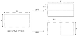
イントラサブパーティション(Intra Sub-Partitions,ISP)ツールは、ルーマイントラ予測されたブロックを、ブロックサイズに応じて、垂直又は水平方向に2又は4つのサブパーティションに分割する。例えば、ISPの最小ブロックサイズは4×8(又は8×4)である。ブロックサイズが4×8(又は8×4)よりも大きい場合には、対応するブロックは4つのサブパーティションによって分割される。図5は、2つの可能性の例を示す。全てのサブパーティションは、少なくとも16個のサンプルを有するという条件を満たす。
2.4 Intra Subpartition (ISP)
The Intra Sub-Partitions (ISP) tool divides the luma intra-predicted block vertically or horizontally into 2 or 4 sub-partitions depending on the block size. For example, ISP's minimum block size is 4×8 (or 8×4). If the block size is larger than 4x8 (or 8x4), the corresponding block is divided by 4 sub-partitions. FIG. 5 shows examples of two possibilities. All subpartitions meet the condition of having at least 16 samples.
サブパーティションごとに、再構成されたサンプルは、残差信号を予測信号に加えることによって取得される。ここで、残差信号は、エントロピ復号化、逆量子化及び逆変換などのプロセスによって生成される。従って、各サブパーティションの再構成されたサンプル値は、次のサブパーティションの予測を生成するために利用可能であり、各サブパーティションは、繰り返し処理される。更には、処理されるべき最初のサブパーティションは、CUの左上サンプルを含み、次いで下方向に(水平分割)又は右方向に(垂直分割)続くものである。結果として、サブパーティション予測信号を生成するために使用される参照サンプルは、ラインの左側及び上側にのみ位置している。全てのサブパーティションは、同じイントラモードを共有する。 For each sub-partition, reconstructed samples are obtained by adding the residual signal to the prediction signal. Here, the residual signal is generated by processes such as entropy decoding, inverse quantization and inverse transform. Thus, the reconstructed sample values for each sub-partition are available to generate predictions for the next sub-partition, and each sub-partition is iteratively processed. Furthermore, the first subpartition to be processed contains the top left sample of the CU, and then continues downward (horizontal split) or rightward (vertical split). As a result, the reference samples used to generate the sub-partition prediction signal are located only on the left and top sides of the line. All subpartitions share the same intra mode.
2.5 アフィン線形重み付きイントラ予測(ALWIP又はマトリクスベースイントラ予測)
アフィン線形重み付きイントラ予測(ALWIP、マトリクスベースイントラ予測(MIP)の別名でも知られる)は、JVET-N0217で提案されている。
2.5 Affine Linear Weighted Intra Prediction (ALWIP or Matrix-Based Intra Prediction)
Affine Linear Weighted Intra Prediction (ALWIP, also known as Matrix-Based Intra Prediction (MIP)) is proposed in JVET-N0217.
JVET-N0127では、2つのテストが行われる。テスト1では、ALWIPは、8Kバイトのメモリ制限及びサンプルあたり多くても4回の乗算で設計される。テスト2は、テスト1と類似しているが、メモリ要件及びモデルアーキテクチャに関して設計を単純化している。
Two tests are performed in JVET-N0127. In
○ 全てのブロック形状について、マトリクス及びオフセットベクトルの1つの組。 o One set of matrices and offset vectors for all block shapes.
○ 全てのブロック形状について、モード数を19に低減。 ○ Reduced number of modes to 19 for all block shapes.
○ メモリ要件を5760個の10ビット値、つまり、7.20キロバイトに低減。 o Reduced memory requirements to 5760 10-bit values, or 7.20 kilobytes.
○ 予測されたサンプルの線形補間が、第1テストで見られる反復補間を置き換えて、方向ごとに1つのステップで実行される。 o A linear interpolation of the predicted samples is performed, one step per direction, replacing the iterative interpolation seen in the first test.
2.5.1 JVET-N0217のテスト1
幅W及び高さHの長方形ブロックのサンプルを予測するために、アフィン線形重み付きイントラ予測(ALWIP)は、ブロックの左にあるH個の再構成された隣接境界サンプルの1列と、ブロックの上にあるW個の再構成された隣接境界サンプルの1列とを入力として取る。再構成されたサンプルが利用不可能である場合には、それらは、従来のイントラ予測で行われるように生成される。
2.5.1
To predict a rectangular block of samples of width W and height H, affine linear weighted intra prediction (ALWIP) uses a column of H reconstructed adjacent boundary samples to the left of the block and Take as input a column of W reconstructed adjacent boundary samples above. If reconstructed samples are not available, they are generated as is done in conventional intra-prediction.
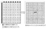
境界サンプルの中から、W=H=4の場合には4つのサンプルが、他の全ての場合には8つのサンプルが、平均化によって抽出される。 Among the boundary samples, 4 samples are extracted by averaging when W=H=4 and 8 samples in all other cases.
マトリクスベクトル乗算及びそれに続くオフセットの加算は、平均化されたサンプルを入力として実行される。その結果、元のブロックのサンプルのサブサンプリングされたセットに関する予測信号は低減される。 A matrix-vector multiplication followed by offset addition is performed with the averaged samples as input. As a result, the prediction signal for the subsampled set of samples of the original block is reduced.
残りのポジションでの予測信号は、方向ごとに単一ステップの線形補間である線形補間によって、サブサンプリングされたセットに関する予測信号から生成される。 The predictions at the remaining positions are generated from the predictions for the subsampled set by linear interpolation, which is a single step linear interpolation for each direction.
予測信号を生成するために必要なマトリクス及びオフセットベクトルは、マトリクスの3つのセットS0、S1、S2から取られる。セットS0は、各マトリクスが16個の行及び4つの列を有する18個の行列A0
i(i∈{0,・・・,17})と、夫々のサイズが16である18個のオフセットベクトルb0
i(i∈{0,・・・,17})とから成る。そのセットのマトリクス及びオフセットは、サイズ4×4のブロックのために使用される。セットS1は、各マトリクスが16個の行及び8つの列を有する10個の行列A1
i(i∈{0,・・・,9})と、夫々のサイズが16である10個のオフセットベクトルb1
i(i∈{0,・・・,9})とから成る。そのセットのマトリクス及びオフセットは、サイズ4×8、8×4、及び8×8のブロックのために使用される。最後に、セットS2は、各マトリクスが64個の行及び8つの列を有する6つの行列A2
i(i∈{0,・・・,5})と、夫々のサイズが64である6つのオフセットベクトルb2
i(i∈{0,・・・,5})とから成る。そのセットのマトリクス及びオフセットは、全ての他のブロック形状のために使用される。
The matrices and offset vectors needed to generate the prediction signals are taken from three sets of matrices S 0 , S 1 , S 2 . The set S 0 consists of 18 matrices A 0 i (iε{0, . . . , 17}) with each matrix having 16 rows and 4 columns and 18 and offset vectors b 0 i (iε{0, . . . , 17}). That set of matrices and offsets is used for blocks of
マトリクスベクトル席の計算に必要な乗算の総数は、常に、4×W×H以下である。つまり、サンプルあたり多くても4回の乗算がALWIPモードのために必要とされる。 The total number of multiplications required to compute a matrix vector seat is always less than or equal to 4*W*H. That is, at most four multiplications per sample are required for ALWIP mode.
2.5.2 境界の平均化
第1ステップで、入力される境界bdrytop及びbdryleftは、より小さい境界bdryred
top及びbdryred
leftに低減される。ここで、bdryred
top及びbdryred
leftは両方とも、4×4ブロックの場合には2つのサンプルから成り、他の全ての場合には4つのサンプルから成る。
2.5.2 Boundary Averaging In a first step, the incoming bounds bdry_top and bdry_left are reduced to smaller bounds bdry_red_top and bdry_red_left . where bdry_red_top and bdry_red_left both consist of 2 samples for 4x4 blocks and 4 samples for all other cases.
4×4ブロックの場合に、0≦i<2については、

さもなければ、ブロック幅WがW=4・2kとして与えられる場合に、0≦i<4については、

2つの低減された境界bdryred
top及びbdryred
leftは、低減された境界ベクトルbdryredに連結される。よって、低減された境界ベクトルbdryredは、4×4形状のブロックについてはサイズが4であり、他の全ての形状のブロックについてはサイズが8である。modeがALWIPモードを指す場合に、この連結は、次のように定義される:

最終的に、サブサンプリングされた予測信号の補間のために、大きいブロックに対しては、平均された境界の第2バージョンが必要とされる。つまり、min(W,H)>8かつW≧Hである場合に、W=8*2lと記述され、0≦i<8については、

min(W,H)>8かつH>Wである場合に、bdryred leftが同様に定義される。 bdry red left is similarly defined if min(W, H)>8 and H>W.
2.5.3 マトリクスベクトル乗算による低減された予測信号の生成
低減された入力ベクトルbdryredから、低減された予測信号predredを生成する。後者の信号は、幅Wred及び高さHredのダウンサンプリングされたブロックに関する信号である。ここで、Wred及びHredは、

低減された予測信号predredは、マトリクスベクトル積を計算してオフセットを加えることによって、計算される:
predred=A・bdryred+b
The reduced prediction signal pred_red is computed by computing the matrix-vector product and adding an offset:
pred red =A*bdry red +b
ここで、Aは、Wred・Hred個の行と、W=H=4の場合に4つの列、他の全ての場合に8つの列とを有するマトリクスである。bは、サイズWred・Hredのベクトルである。 where A is a matrix with W red H red rows and 4 columns if W=H=4 and 8 columns in all other cases. b is a vector of size W red · H red .
マトリクスA及びベクトルbは、次のように、セットS0、S1、S2のうちの1つから取られる。次のように、インデックスidx=idx(W,H)を定義する:

更に、次のように、mを置く:

次いで、idx≦1又はidx=2かつmin(W,H)>4である場合に、A=Aidx m及びb=bidx mを置く。idx=2かつmin(W,H)=4である場合に、Aを、W=4である場合には、ダウンサンプリングされたブロック内の奇数x座標に対応し、あるいは、H=4である場合には、ダウンサンプリングされたブロック内の奇数y座標に対応するAidx mのあらゆる行を除くことによって現れるマトリクスであるとする。 Then put A=A idx m and b=b idx m if idx≦1 or idx=2 and min(W,H)>4. A if idx=2 and min(W,H)=4 corresponds to an odd x-coordinate in the downsampled block if W=4, or H=4 If , be the matrix that appears by removing every row of A idx m that corresponds to an odd y-coordinate in the downsampled block.
最終的に、低減された予測信号は、次の場合に、その転置で置換される:
○ W=H=4かつmode≧18
○ max(W,H)=8かつmode≧10
○ max(W,H)>8かつmode≧6
Finally, the reduced prediction signal is replaced by its transpose when:
o W=H=4 and mode≧18
o max(W, H)=8 and mode≧10
o max(W, H) > 8 and mode > 6
predredの計算に必要な乗算の数は、W=H=4の場合に4である。これは、この場合に、Aが4つの列及び16個の行を有するからである。他の全ての場合に、Aは、8つの列及びWred・Hred個の行を有しており、このような場合には、8・Wred・Hred≦4・W・H回の乗算が必要とされると直ちに確かめられる。つまり、これらの場合にも、サンプルあたり多くても4回の乗算が、predredを計算するために必要とされる。 The number of multiplications required to compute pred red is 4 if W=H=4. This is because in this case A has 4 columns and 16 rows. In all other cases, A has 8 columns and W red · H red rows, in which case 8 · W red · H red ≤ 4 · W · H It is verified immediately when multiplication is required. That is, even in these cases, at most four multiplications per sample are required to compute pred_red .
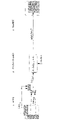
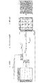
2.5.4 ALWIPプロセス全体の説明
平均化、マトリクスベクトル乗算及び線形補間の全プロセスは、図6~9において異なる形状ごとに説明されている。残りの形状は、表されている場合のうちの1つで見られるように扱われることに留意されたい。
2.5.4 Overall ALWIP Process Description The overall process of averaging, matrix-vector multiplication and linear interpolation is illustrated for different shapes in FIGS. Note that the remaining shapes are treated as seen in one of the cases represented.
1.4×4ブロックを考えると、ALWIPは、境界の各軸に沿って2つの平均を取る。結果として得られる4つの入力サンプルがマトリクスベクトル乗算に入る。マトリクスは、セットS0から取られる。オフセットを加えた後、これは、16個の最終的な予測サンプルをもたらす。線形補間は、予測信号を生成するために必要とされな。よって、サンプルあたり全部で(4・16)/(4・4)=4回の乗算が実行される。 Given a 1.4×4 block, ALWIP takes two averages along each axis of the boundary. The resulting four input samples enter the matrix-vector multiplication. The matrix is taken from set S0 . After adding the offset, this yields 16 final prediction samples. No linear interpolation is required to generate the prediction signal. Thus, a total of (4·16)/(4·4)=4 multiplications are performed per sample.
2.8×8ブロックを考えると、ALWIPは、境界の各軸に沿って4つの平均を取る。結果として得られる8つの入力サンプルがマトリクスベクトル乗算に入る。マトリクスは、セットS1から取られる。これは、予測ブロックの奇数ポジションでの16個のサンプルをもたらす。よって、サンプルあたり全部で(8・16)/(8・8)=2回の乗算が実行される。オフセットを加えた後、これらのサンプルは、低減された上境界を使用することによって垂直方向で補間される。水平補間は、元の左境界を使用することによって続く。 Given a 2.8×8 block, ALWIP takes four averages along each axis of the boundary. The resulting eight input samples enter the matrix-vector multiplication. The matrix is taken from set S1. This yields 16 samples at odd positions in the prediction block. Thus, a total of (8·16)/(8·8)=2 multiplications are performed per sample. After adding the offset, these samples are vertically interpolated by using the reduced upper bound. Horizontal interpolation continues by using the original left boundary.
3.8×4ブロックを考えると、ALWIPは、境界の水平軸に沿って4つの平均を、及び左境界において4つの元の境界値を取る。結果として得られる8つの入力サンプルがマトリクスベクトル乗算に入る。マトリクスは、セットS1から取られる。これは、予測ブロックの奇数水平ポジション及び各垂直ポジションでの16個のサンプルをもたらす。よって、サンプルあたり全部で(8・16)/(8・4)=4回の乗算が実行される。オフセットを加えた後、これらのサンプルは、元の左境界を使用することによって水平方向で補間される。 Given a 3.8×4 block, ALWIP takes 4 averages along the horizontal axis of the boundary and 4 original boundary values at the left boundary. The resulting eight input samples enter the matrix-vector multiplication. The matrix is taken from set S1. This yields 16 samples at odd horizontal positions and each vertical position of the prediction block. Thus, a total of (8·16)/(8·4)=4 multiplications are performed per sample. After adding the offset, these samples are interpolated horizontally by using the original left boundary.
4.16×16ブロックを考えると、ALWIPは、境界の各軸に沿って4つの平均を取る。結果として得られる8つの入力サンプルがマトリクスベクトル乗算に入る。マトリクスは、セットS2から取られる。これは、予測ブロックの奇数ポジションでの64個のサンプルをもたらす。よって、サンプルあたり全部で(8・64)/(16・16)=2回の乗算が実行される。オフセットを加えた後、これらのサンプルは、上境界の8つの平均を使用することによって垂直方向で補間される。水平補間は、元の左境界を使用することによって続く。補間プロセスは、この場合に、如何なる乗算も加えない。そのため、全部で、サンプルあたり2回乗算が、ALWIP予測を計算するために必要とされる。 Given a 4.16×16 block, ALWIP takes four averages along each axis of the boundary. The resulting eight input samples enter the matrix-vector multiplication. The matrix is taken from set S2. This yields 64 samples at odd positions in the prediction block. Thus, a total of (8·64)/(16·16)=2 multiplications are performed per sample. After adding the offset, these samples are vertically interpolated by using the eight averages of the upper bound. Horizontal interpolation continues by using the original left boundary. The interpolation process does not add any multiplication in this case. So, in total, two multiplications per sample are required to compute the ALWIP prediction.
より大きい形状については、プロシージャは本質的に同じであり、サンプルあたりの乗算の数が4よりも少ないことをチェックすることは容易である。 For larger shapes the procedure is essentially the same and it is easy to check that the number of multiplications per sample is less than 4.
W>8である場合に、W×8ブロックについては、サンプルが奇数水平ポジション及び各垂直ポジションで与えられるということで、水平補間のみが必要である。 If W>8, then for W×8 blocks only horizontal interpolation is needed, in that samples are given at odd horizontal positions and at each vertical position.
最後に、W>8である場合に、W×4ブロックについては、ダウンサンプリングされたブロックの水平軸に沿った奇数エントリに対応するあらゆる行を除くことによって現れるマトリクスをA_kbeとする。よって、出力サイズは32であり、やはり、水平補間のみが実行される。 Finally, for W×4 blocks, where W>8, let A_kbe be the matrix that results from removing every row corresponding to an odd entry along the horizontal axis of the downsampled block. So the output size is 32 and again only horizontal interpolation is performed.
転置された場合は、然るべく扱われる。 If transposed, it is treated accordingly.
2.5.5 単一ステップの線形補間
max(W,H)≧8である場合に、W×Hブロックについては、予測信号は、線形補間によってWred×Hredでの低減された信号predredから生じる。ブロック形状に応じて、線形補間は、垂直方向、水平方向、又は両方の方向において行われる。線形補間が両方の方向において適用されるべき場合に、それは、W<Hである場合には、最初に水平方向において適用され、そうでない場合には、最初に垂直方向において適用される。
2.5.5 Single-Step Linear Interpolation For W×H blocks, if max(W,H)≧8, the prediction signal is the reduced signal pred at W red ×H red by linear interpolation. arises from red . Depending on the block shape, linear interpolation can be done vertically, horizontally, or both. If linear interpolation is to be applied in both directions, it is applied first in the horizontal direction if W<H, otherwise it is applied first in the vertical direction.
一般性を失わずに、max(W,H)≧8かつW≧HのW×Hブロックを考える。その場合に、一次元の線形補間は次のように実行される。一般性を失わずに、垂直方向における線形補間について記載すれば十分である。最初に、低減された予測信号は、境界信号によって上に拡張される。垂直アップサンプリング係数Uver=H/Hredを定義し、Uver=2Uver>1と記載する。その場合に、拡張された低減された予測信号を:

次いで、この拡張された低減された予測信号から、垂直方向に線形補間された予測信号が:

2.5.6 提案されているイントラ予測モードのシグナル伝達
イントラモードでのコーディングユニット(Coding Unit,CU)ごとに、ALWIPモードが対応する予測ユニット(Prediction Unit,PU)に適用されるべきであるか否かを示すフラグは、ビットストリームで送信される。後者のインデックスのシグナル伝達は、JVET-M0043と同じ方法でMRLと調和する。ALWIPモードが適用されるべきである場合に、ALWIPモードのインデックスpredmodeは、3つのMPSを含むMPMリストを用いてシグナリングされる。
2.5.6 Proposed Intra Prediction Mode Signaling For each Coding Unit (CU) in intra mode, ALWIP mode should be applied to the corresponding Prediction Unit (PU). A flag indicating whether or not is transmitted in the bitstream. Signaling of the latter index is consistent with MRL in the same way as JVET-M0043. If ALWIP mode is to be applied, the ALWIP mode index predmode is signaled using an MPM list containing 3 MPS.
ここで、MPMの導出は、次のように、上側及び左側のPUのイントラモードを用いて実行される。ALWIPモードを各従来のイントラ予測モードpredmodeAngularに割り当てる3つの固定テーブルmap_angular_to_alwipidx(idx∈{0,1,2})が存在する:
predmodeALWIP
=map_angular_to_alwipidx[predmodeAngular]
Here, the MPM derivation is performed using the intra modes of the upper and left PUs as follows. There are three fixed tables map_angular_to_alwip idx (idxε{0,1,2}) that assign ALWIP modes to each conventional intra-prediction mode predmode Angular :
predmode ALWIP
=map_angular_to_alwip idx [predmode Angular ]
幅W及び高さHのPUごとに、3つのセットのうちのどれからALWIPパラメータがセクション2.5.3で取られるべきかを示すインデックスを定義する:
idx(PU)=idx(W,H)∈{0,1,2}
For each PU of width W and height H, define an index indicating from which of the three sets the ALWIP parameters should be taken in section 2.5.3:
idx(PU)=idx(W,H)ε{0,1,2}
上側予測ユニットPUaboveが利用可能であって、現在のPUと同じCTUに属し、イントラモードにある場合に、idx(PU)=idx(PUabove)であるならば、かつ、ALWIPがALWIPモードpredmodeALWIP
aboveでPUaboveに適用されるならば:
modeALWIP
above=predmodeALWIP
above
を置く。
If the upper prediction unit PU above is available, belongs to the same CTU as the current PU, and is in intra mode, then idx(PU)=idx(PU above ), and ALWIP is ALWIP mode predmode If applied to a PU above with ALWIP above :
mode ALWIP above =predmode ALWIP above
put the
上側PUが利用可能であって、現在のPUと同じCTUに属し、イントラモードにある場合に、従来のイントラ予測モードpredmodeAngular
aboveが上側PUに適用されるならば:
modeALWIP
above=map_angular_to_alwipidx(PUabove)[predmodeAngular
above]
を置く。
If the upper PU is available, belongs to the same CTU as the current PU, and is in intra mode, then the conventional intra prediction mode predmode Angular above is applied to the upper PU:
mode ALWIP above = map_angular_to_alwip idx (PU above) [predmode Angular above ]
put the
他の全ての場合に:
modeALWIP
above=-1
を置く。これは、このモードが利用不可能であることを意味する。同じように、しかし、左側PUが現在のPUと同じCTUに属する必要があるという制限なしで、モードmodeALWIP
leftを導出する。
In all other cases:
mode ALWIP above = -1
put the This means that this mode is not available. Similarly, derive the mode mode ALWIP left , but without the restriction that the left PU must belong to the same CTU as the current PU.
最後に、3つの固定デフォルトリストlistidx(idx∈{0,1,2})が与えられる。各リストは3つの相異なるALWIPモードを含む。デフォルトリストlistidx(PU)並びにモードmodeALWIP above及びmodeALWIP leftから、デフォルト値に-1を代入し、繰り返しを排除することによって、3つの相異なるMPMを構成する。 Finally, three fixed default lists list idx (idxε{0,1,2}) are provided. Each list contains three different ALWIP modes. From the default list list idx(PU) and modes mode ALWIP above and mode ALWIP left , construct three different MPMs by substituting -1 for the default value and eliminating repetitions.
ALWIP MPMリスト構成で使用される左隣接ブロック及び上隣接ブロックは、図10に示されるA1及びB1である。 The left neighbor and top neighbor blocks used in ALWIP MPM list construction are A1 and B1 shown in FIG.
2.5.7 従来のルーマ及びクロマイントラ予測モードのための適応MPMリスト導出
提案されているALWIPモードは、次のように、従来のイントラ予測モードのMPMベースコーディングと調和する。従来のイントラ予測モードのルーマ及びクロマMPMリスト導出プロセスは、所与のPUに関してALWIPモードpredmodeALWIPを従来のイントラ予測モードの1つにマッピングする固定テーブルmap_alwip_to_angularidx(idx∈{0,1,2})を使用する:
predmodeAngular
=map_alwip_to_angularidx[predmodeALWIP]
2.5.7 Adaptive MPM list derivation for conventional luma and chroma intra-prediction modes The proposed ALWIP mode harmonizes with the MPM-based coding of conventional intra-prediction modes as follows. The traditional intra prediction mode luma and chroma MPM list derivation process uses a fixed table map_alwip_to_angular idx (idx ∈ {0,1,2}) that maps the ALWIP mode predmode ALWIP to one of the conventional intra prediction modes for a given PU. ) using:
Predmode Angular
=map_alwip_to_angular idx [predmode ALWIP ]
ルーマMPMリスト導出のために、ALWIPモードpredmodeALWIPを使用する隣接ルーマブロックに遭遇するときにはいつでも、このブロックは、それがあたかも従来のイントラ予測モードpredmodeAngularを使用しているかのように扱われる。クロマMPMリスト導出のために、現在のルーマブロックがALWIPモードを使用するときにはいつでも、同じマッピングが、ALWIPモードを従来のイントラ予測モードに変換するために使用される。 For luma MPM list derivation, whenever a neighboring luma block using ALWIP mode predmode ALWIP is encountered, this block is treated as if it were using conventional intra-prediction mode predmode Angular . For chroma MPM list derivation, whenever the current luma block uses ALWIP mode, the same mapping is used to convert ALWIP mode to conventional intra-prediction mode.
2.5.8 対応する修正された作業草案
いくつかの実施形態において、このセクションで記載されるように、intra_lwip_frag、intra_lwip_mpm_flag、intra_lwip_mpm_idx及びintra_lwip_mpm_remainderに関連する部分が、開示されている技術の実施形態に基づいて作業草案に加えられている。
2.5.8 Corresponding Modified Working Drafts In some embodiments, portions relating to intra_lwip_flag, intra_lwip_mpm_flag, intra_lwip_mpm_idx, and intra_lwip_mpm_remainder, as described in this section, may be modified according to embodiments of the disclosed technology. have been added to the working draft.
いくつかの実施形態において、このセクションで記載されるように、<begin>及び<end>タグは、開示されている技術の実施形態に基づいた作業草案に対する追加及び修正を表すために使用される。 In some embodiments, as described in this section, <begin> and <end> tags are used to represent additions and modifications to working drafts based on embodiments of the disclosed technology. .


ALWIPの概要
幅W及び高さHの長方形ブロックのサンプルを予測するために、アフィン線形重み付きイントラ予測(ALWIP)は、ブロックの左にあるH個の再構成された隣接境界サンプルの1列と、ブロックの上にあるW個の再構成された隣接境界サンプルの1列とを入力として取る。再構成されたサンプルが利用不可能である場合には、それらは、従来のイントラ予測で行われるように生成される。ALWIPは、ルーマイントラブロックにのみ適用される。クロマイントラブロックについては、従来のイントラコーディングモードが適用される。
Overview of ALWIP To predict a rectangular block of samples of width W and height H, affine linear weighted intra prediction (ALWIP) uses a column of H reconstructed adjacent boundary samples to the left of the block and , and a column of W reconstructed neighboring boundary samples over the block as inputs. If reconstructed samples are not available, they are generated as is done in conventional intra-prediction. ALWIP only applies to luma intra blocks. For chroma intra blocks, the conventional intra-coding mode is applied.
予測信号の生成は、次の3つのステップに基づく:
1.境界サンプルの中から、W=H=4の場合には4つのサンプルが、他の全ての場合には8つのサンプルが、平均化によって抽出される。
2.マトリクスベクトル乗算及びそれに続くオフセットの加算が、平均化されたサンプルを入力として実行される。その結果、元のブロックのサンプルのサブサンプリングされたセットに関する予測信号は低減される。
3.残りのポジションでの予測信号が、方向ごとに単一ステップの線形補間である線形補間によって、サブサンプリングされたセットに関する予測信号から生成される。
The prediction signal generation is based on the following three steps:
1. Among the boundary samples, 4 samples are extracted by averaging when W=H=4 and 8 samples in all other cases.
2. A matrix-vector multiplication followed by offset addition is performed with the averaged samples as input. As a result, the prediction signal for the subsampled set of samples of the original block is reduced.
3. Predictions at the remaining positions are generated from the predictions for the subsampled set by linear interpolation, which is a single step linear interpolation for each direction.
ALWIPモードが適用されるべきである場合に、ALWIPモードのインデックスpredmodeは、3つのMPMを含むMPMリストを用いてシグナリングされる。ここで、MPMの導出は、次のように、上側及び左側のPUのイントラモードを用いて実行される。ALWIPモードを各従来のイントラ予測モードpredmodeAngularに割り当てる3つの固定テーブルmap_angular_to_alwipidx(idx∈{0,1,2})が存在する:
predmodeALWIP
=map_angular_to_alwipidx[predmodeAngular]
If ALWIP mode is to be applied, the ALWIP mode index predmode is signaled using an MPM list containing three MPMs. Here, the MPM derivation is performed using the intra modes of the upper and left PUs as follows. There are three fixed tables map_angular_to_alwip idx (idxε{0,1,2}) that assign ALWIP modes to each conventional intra-prediction mode predmode Angular :
predmode ALWIP
=map_angular_to_alwip idx [predmode Angular ]
幅W及び高さHのPUごとに、3つのセットのうちのどれからALWIPパラメータが取られるべきかを示すインデックスを定義する:
idx(PU)=idx(W,H)∈{0,1,2}
For each PU of width W and height H, define an index indicating from which of the three sets the ALWIP parameters should be taken:
idx(PU)=idx(W,H)ε{0,1,2}
上側予測ユニットPUaboveが利用可能であって、現在のPUと同じCTUに属し、イントラモードにある場合に、idx(PU)=idx(PUabove)であるならば、かつ、ALWIPがALWIPモードpredmodeALWIP
aboveでPUaboveに適用されるならば:
modeALWIP
above=predmodeALWIP
above
を置く。
If the upper prediction unit PU above is available, belongs to the same CTU as the current PU, and is in intra mode, then idx(PU)=idx(PU above ), and ALWIP is ALWIP mode predmode If applied to a PU above with ALWIP above :
mode ALWIP above =predmode ALWIP above
put the
上側PUが利用可能であって、現在のPUと同じCTUに属し、イントラモードにある場合に、従来のイントラ予測モードpredmodeAngular
aboveが上側PUに適用されるならば:
modeALWIP
above=map_angular_to_alwipidx(PUabove)[predmodeAngular
above]
を置く。
If the upper PU is available, belongs to the same CTU as the current PU, and is in intra mode, then the conventional intra prediction mode predmode Angular above is applied to the upper PU:
mode ALWIP above = map_angular_to_alwip idx(PU above) [predmode Angular above ]
put the
他の全ての場合に:
modeALWIP
above=-1
を置く。これは、このモードが利用不可能であることを意味する。同じように、しかし、左側PUが現在のPUと同じCTUに属する必要があるという制限なしで、モードmodeALWIP
leftを導出する。
In all other cases:
mode ALWIP above = -1
put the This means that this mode is not available. Similarly, derive the mode mode ALWIP left , but without the restriction that the left PU must belong to the same CTU as the current PU.
最後に、3つの固定デフォルトリストlistidx(idx∈{0,1,2})が与えられる。各リストは3つの相異なるALWIPモードを含む。デフォルトリストlistidx(PU)並びにモードmodeALWIP above及びmodeALWIP leftから、デフォルト値に-1を代入し、繰り返しを排除することによって、3つの相異なるMPMを構成する。 Finally, three fixed default lists list idx (idxε{0,1,2}) are provided. Each list contains three different ALWIP modes. From the default list list idx(PU) and modes mode ALWIP above and mode ALWIP left , construct three different MPMs by substituting -1 for the default value and eliminating repetitions.
ルーマMPMリスト導出のために、ALWIPモードpredmodeALWIPを使用する隣接ルーマブロックに遭遇するときにはいつでも、このブロックは、それがあたかも従来のイントラ予測モードpredmodeAngularを使用しているかのように扱われる。
predmodeAngular
=map_alwip_to_angularidx[predmodeALWIP]
For luma MPM list derivation, whenever a neighboring luma block using ALWIP mode predmode ALWIP is encountered, this block is treated as if it were using conventional intra-prediction mode predmode Angular .
Predmode Angular
=map_alwip_to_angular idx [predmode ALWIP ]
3 VVCでの変換
3.1 多重変換選択(MTS)
HEVCで用いられているDCT-IIに加えて、多重変換選択(Multiple Transform Selection,MTS)スキームが、インターコーディングされたブロック及びイントラコーディングされたブロックの両方をコーディングする残差のために使用される。それは、DCT8/DST7からの複数の選択された変換を使用する。新たに導入された変換マトリクスは、DST-VII及びDCT-VIIIである。
3 Conversion in VVC 3.1 Multiple Conversion Selection (MTS)
In addition to DCT-II used in HEVC, a Multiple Transform Selection (MTS) scheme is used for residual coding both inter- and intra-coded blocks. . It uses multiple selected transforms from DCT8/DST7. The newly introduced transform matrices are DST-VII and DCT-VIII.
3.2 JVET-N0193で提案されている縮小された2次変換(RST)
縮小された2次変換(Reduced Secondary Transform,RST)は、4×4及び8×8について夫々、16×16及び16×64の分離不可能な変換を適用する。1次の順方向及び逆方向の変換は依然として、2つの1次元(1-D)水平/垂直変換パスと同じように実行される。2次の順方向及び逆方向の変換は、1次変換のそれとは別のプロセスステップである。エンコーダについては、1次順方向変換が最初に実行され、次いで、2次順方向変換及び量子化、そして、CABACビット符号化が続く。デコーダについては、CABACビット復号化及び逆量子化、それから2次逆方向変換が最初に実行され、次いで、1次逆方向変換が続く。RSTは、イントラスライス及びインタースライスの両方
で、イントラコーディングされたTUにのみ適用される。
3.2 Reduced Quadratic Transform (RST) proposed in JVET-N0193
The Reduced Secondary Transform (RST) applies 16x16 and 16x64 non-separable transforms for 4x4 and 8x8, respectively. First-order forward and inverse transforms are still performed in the same way as two one-dimensional (1-D) horizontal/vertical transform passes. The second order forward and inverse transforms are separate process steps from that of the first order transform. For the encoder, the first order forward transform is performed first, followed by the second order forward transform and quantization, followed by CABAC bit encoding. For the decoder, CABAC bit decoding and inverse quantization, then secondary inverse transform are first performed, followed by primary inverse transform. RST is only applied to intra-coded TUs in both intra-slice and inter-slice.
統合された6-MPMリストは、多重参照ライン(Multiple Reference Line,MRL)及びイントラサブパーティション(Intra Sub-Partition,ISP)コーディングツールが適用されるか否かに関わらず、イントラブロックに対して提案されている。MPMリストは、VTM4.0で見られるように左側及び上側隣接ブロックのイントラモードに基づき構成される。左側のモードはLeftと表され、上側ブロックのモードはAboveと表されるとすれば、統合MPMリストは次のように構成される:
● 隣接するブロックが利用不可能であるとき、そのイントラモードはデフォルトでプレーナー(Planar)にセットされる。
● Left及びAboveの両モードが非角度モードである場合:
a. MPAリスト→{Planar,DC,V,H,V-4,V+4}
● Left及びAboveのうちの一方のモードが角度モードであり、他方が非角度である場合:
a. Left及びAboveのうちの大きい方のモードとしてモードMaxをセット
b. MPMリスト→{Planar,Max,DC,Max-1,Max+1,Max-2}
● Left及びAboveが両方とも角度であり、それらが異なる場合:
a. Left及びAboveのうちの大きい方のモードとしてモードMaxをセット
b. モードLeft及びAboveの差が2以上62以下の範囲内にある場合:
i. MPMリスト→{Planar,Left,Above,DC,Max-1,Max+1}
c. そうでない場合
i. MPMリスト→{Planar,Left,Above,DC,Max-2,Max+2}
● Left及びAboveが両方とも角度であり、それらが同じである場合:
a. MPMリスト→{Planar,Left,Left-1,Left+1,DC,Lef-2}
A unified 6-MPM list is proposed for intra blocks regardless of whether Multiple Reference Line (MRL) and Intra Sub-Partition (ISP) coding tools are applied. It is The MPM list is constructed based on the intra mode of the left and top neighboring blocks as seen in VTM 4.0. If the mode of the left side is denoted Left and the mode of the upper block is denoted Above, then the consolidated MPM list is constructed as follows:
- When an adjacent block is unavailable, its intra mode defaults to Planar.
● If both Left and Above modes are non-angle modes:
a. MPA list → {Planar, DC, V, H, V-4, V+4}
- If one mode of Left and Above is angular mode and the other is non-angular:
a. Set mode Max as the larger mode of Left and Above b. MPM list → {Planar, Max, DC, Max-1, Max+1, Max-2}
- If Left and Above are both angles and they are different:
a. Set mode Max as the larger mode of Left and Above b. If the difference between modes Left and Above is in the range of 2 to 62:
i. MPM list → {Planar, Left, Above, DC, Max-1, Max+1}
c. if not
i. MPM list → {Planar, Left, Above, DC, Max-2, Max+2}
- If Left and Above are both angles and they are the same:
a. MPM list → {Planar, Left, Left-1, Left+1, DC, Lef-2}
その上、MPMインデックスコードワードの第1ビンは、CABACコンテキストコード化される。現在のイントラブロックがMRLを有効にされているか、ISPを有効にされているかどうか、あるいは、通常のイントラブロックであるかどうかに対応して、全部で3つのコンテキストが使用される。 Additionally, the first bin of the MPM index codeword is CABAC context coded. A total of three contexts are used, depending on whether the current intra block is MRL enabled, ISP enabled, or a normal intra block.
統合MPMリスト構成で使用される左隣接ブロック及び上隣接ブロックは、図10に示されるA2及びB2である。 The left neighbor block and above neighbor block used in the combined MPM list construction are A2 and B2 shown in FIG.
1つのMPMフラグが最初にコーディングされる、ブロックがMPMリスト内のモードの1つでコーディングされる場合に、MPMインデックスが更にコーディングされる。そうでない場合には、残りのモード(MPMを除く)へのインデックスがコーディングされる。 An MPM index is also coded if the block is coded in one of the modes in the MPM list, where one MPM flag is coded first. Otherwise, the indices to the remaining modes (except MPM) are coded.
4 既存の実施における欠点の例
JVET-N0217でのALWIPの設計には、次の問題がある。
4 Examples of shortcomings in existing implementations The design of ALWIP in JVET-N0217 has the following problems.
1)2019年3月のJVET会議で、統合6-MPMリスト生成がMRLモード、ISPモード、及び通常のイントラモードのために採用された。しかし、アフィン線形重み付き予測モードは、異なった3-MPMリスト構成を使用する。このことは、MPMリスト構成を複雑にする。複雑なMPMリスト構成は、特に、4×4サンプルなどの小さいブロックについて、デコーダのスループットを損なう可能性がある。 1) At the JVET meeting in March 2019, a unified 6-MPM list generation was adopted for MRL mode, ISP mode and normal intra mode. However, the affine linear weighted prediction mode uses a different 3-MPM list construction. This complicates the MPM list construction. Complex MPM list construction can hurt decoder throughput, especially for small blocks such as 4×4 samples.
2)ALWIPは、ブロックのルーマ成分にしか適用されない。ALWPコーディングされたブロックのクロマ成分については、クロマモードインデックスがコーディングされて、デコーダへ送信される。その結果、不必要なシグナリングが生じることがある。 2) ALWIP only applies to the luma component of a block. For chroma components of ALWP coded blocks, the chroma mode index is coded and sent to the decoder. As a result, unnecessary signaling may occur.
3)他のコーディングツールとのALWIPのインタラクションが考慮されるべきである。 3) ALWIP's interaction with other coding tools should be considered.
4)uspBdryXを
![]()
![]()
5)予測サンプルをアップサンプリングするとき、丸めは適用されない。 5) No rounding is applied when upsampling the prediction samples.
7)多すぎるコンテキスト(例えば、4)が、ALWIPフラグ(例えば、intra_lwip_flag)をコーディングする際に使用される。 7) Too many contexts (eg, 4) are used in coding the ALWIP flag (eg, intra_lwip_flag).
8)垂直アップサンプリング及び水平アップサンプリングの両方が必要とされるとき、アップサンプリング順序はブロック形状に依存する。これはハードウェアフレンドリではない。 8) When both vertical and horizontal upsampling are required, the upsampling order depends on the block shape. This is not hardware friendly.
9)線形補間フィルタがアップサンプリングのために使用されるが、これは非効率である場合がある。 9) A linear interpolation filter is used for upsampling, which can be inefficient.
5 マトリクスベースのイントラコーディングのための例示的な方法
目下開示されている技術の実施形態は、既存の実施の欠点を解消し、それによって、コーディング効率はより高いが計算複雑性は低いビデオコーディングをもたらす。ビデオコーディングのための、本明細書で記載されるようなマトリクスベースイントラ予測方法は、既存のビデオコーディング標準規格及び将来のビデオコーディング標準規格の両方を強化することができ、様々な実施について記載された以下の例で説明される。以下で与えられている開示されている技術の例は、一般概念を説明しており、限定として解釈されるよう意図されない。例において、それとは反対に明示的に示されない限りは、これらの例で記載される様々な特徴は組み合わされてもよい。
5 Exemplary Methods for Matrix-Based Intra-Coding Embodiments of the presently disclosed technology overcome shortcomings of existing implementations, thereby providing video coding with higher coding efficiency but lower computational complexity. Bring. Matrix-based intra-prediction methods such as those described herein for video coding can enhance both existing and future video coding standards, and various implementations are described. is explained in the following example. Examples of the disclosed technology provided below illustrate general concepts and are not intended to be construed as limitations. In the examples, various features described in these examples may be combined unless explicitly indicated to the contrary.
以下の説明では、イントラ予測モードは、角度イントラ予測モード(DC、プレーナー、CCLM及び他の可能なイントラ予測モードを含む)を指し、一方、イントラモードは、通常のイントラモード、又はMRL、又はISP、又はALWIPを指す。 In the following description, intra-prediction mode refers to angular intra-prediction mode (including DC, planar, CCLM and other possible intra-prediction modes), while intra-mode refers to normal intra-mode, or MRL, or ISP , or ALWIP.
以下の説明では、「他のイントラモード」は、ALWIPを除いた、通常のイントラモード、又はMRL、又はISPなどの1つ又は複数のイントラモードを指すことがある。 In the following description, "other intra modes" may refer to normal intra modes, excluding ALWIP, or one or more intra modes such as MRL or ISP.
以下の説明では、SatShit(x,n)は、

一例で、offset0及び/又はoffset1は、(1<<n)>>1又は(1<<(n-1))にセットされる。他の例では、offset0及び/又はoffset1は0にセットされる。 In one example, offset0 and/or offset1 are set to (1<<n)>>1 or (1<<(n-1)). In other examples, offset0 and/or offset1 are set to zero.
他の例では、offset0=offset1=((1<<n)>>1)-1又は((1<<(n-1)))-1である。 In other examples, offset0=offset1=((1<<n)>>1)-1 or ((1<<(n-1)))-1.
Clip3(min,max,x)は、

ALWIPのためのMPMリスト構成
1.ALWIPのためのMPMリストの全体又は部分が、非ALWIPイントラモード(例えば、通常のイントラモード、MRL、又はISP)のためのMPMリストを構成するための全体的又は部分的なプロシージャに従って構成され得る、ことが提案される。
a.一例で、ALWIPのためのMPMリストのサイズは、非ALWIPイントラモードのためのMPMリストのそれと同じであってもよい。
i.例えば、MPMリストのサイズは、ALWP及び非ALWIPイントラモードの両方について6である。
b.一例で、ALWIPのためのMPMリストは、非ALWIPイントラモードのためのMPMリストから導出され得る。
i.一例で、非ALWIPイントラモードのためのMPMリストが最初に構成されてもよい。その後に、それらの部分又は全部が、ALWIPコーディングされたブロックのためのMPMリストに更に加えられ得るMPMに変換され得る。
1)代替的に、更に、変換されたMPMをALWIPコーディングされたブロックのためのMPMリストに加えるとき、プルーニングが適用されてもよい。
2)デフォルトのモードが、ALWIPコーディングされたブロックのためのMPMリストに加えられてもよい。
a.一例で、デフォルトのモードは、非ALWIPイントラモードのMPMリストから変換されたものの前に加えられてもよい。
b.代替的に、デフォルトのモードは、非ALWIPイントラモードのMPMリストから変換されたものの後に加えられてもよい。
c.代替的に、デフォルトのモードは、非ALWIPイントラモードのMPMリストから変換されたものと交互に加えられてもよい。
d.一例で、デフォルトのモードは、全種類のブロックについて同じであるよう固定されてもよい。
e.代替的に、デフォルトのモードは、隣接するブロックの利用可能性、隣接するブロックのモード情報、ブロック寸法などのコーディングされた情報に従って決定されてもよい。
ii.一例で、非ALWIPイントラモードのためのMPMリスト内の1つのイントラ予測モードは、ALWIPのためのMPMリストに置かれるときに、その対応するALWIPイントラ予測モードに変換されてもよい。
1)代替的に、非ALWIPイントラモードのためのMPMリスト内の全てのイントラ予測モードは、ALWIPのためのMPMリストを構成するために使用される前に、対応するALWIPイントラ予測モードに変換されてもよい。
2)代替的に、非ALWIPイントラモードのためのMPMリストがALWIPのためのMPMリストを導出するために更に使用される場合に、全ての候補イントラ予測モード(隣接するブロックからのイントラ予測モードと、プレーナー及びDC等のデフォルトのイントラ予測モードとを含んでもよい)が、非ALWIPイントラモードのためのMPMリストを構成するために使用される前に、対応するALWIPイントラ予測モードに変換されてもよい。
3)一例で、2つの変換されたALWIPイントラ予測モードが比較されてもよい。
a.一例で、それらが同じである場合に、それらのうちの一方のみがALWIPのためのMPMリストに置かれ得る。
b.一例で、それらが同じである場合に、それらのうちの一方のみが非ALWIPイントラモードのためのMPMリストに置かれ得る。
iii.一例で、非ALWIPイントラモードのためのMPMリスト内のS個のイントラ予測モードのうちのK個が、ALWIPのためのMPMリストとして選択されてもよい。例えば、Kは3に等しく、Sは6に等しい。
1)一例で、非ALWIPイントラモードのためのMPMリスト内の最初のK個のイントラ予測モードが、ALWIPのためのMPMリストとして選択され得る。
MPM list configuration for ALWIP1 . All or part of the MPM list for ALWIP may be constructed according to the whole or partial procedure for constructing the MPM list for non-ALWIP intramodes (e.g. regular intramode, MRL, or ISP). , is proposed.
a. In one example, the size of the MPM list for ALWIP may be the same as that of the MPM list for non-ALWIP intra mode.
i. For example, the MPM list size is 6 for both ALWP and non-ALWIP intra mode.
b. In one example, the MPM list for ALWIP can be derived from the MPM list for non-ALWIP intra mode.
i. In one example, the MPM list for non-ALWIP intra mode may be configured first. Afterwards, some or all of them can be converted to MPMs that can be further added to the MPM list for ALWIP coded blocks.
1) Alternatively, pruning may also be applied when adding the transformed MPM to the MPM list for the ALWIP coded block.
2) A default mode may be added to the MPM list for ALWIP coded blocks.
a. In one example, the default mode may be prepended to those converted from the MPM list of non-ALWIP intra modes.
b. Alternatively, the default mode may be added after the one converted from the MPM list of non-ALWIP intra modes.
c. Alternatively, the default mode may be alternately added with one converted from the MPM list of non-ALWIP intra modes.
d. In one example, the default mode may be fixed to be the same for all types of blocks.
e. Alternatively, the default mode may be determined according to coded information such as neighboring block availability, neighboring block mode information, block dimensions, and the like.
ii. In one example, one intra-prediction mode in the MPM list for non-ALWIP intra-mode may be converted to its corresponding ALWIP intra-prediction mode when placed in the MPM list for ALWIP.
1) Alternatively, all intra-prediction modes in the MPM list for non-ALWIP intra-modes are converted to corresponding ALWIP intra-prediction modes before being used to construct the MPM list for ALWIP. may
2) Alternatively, all candidate intra-prediction modes (intra-prediction modes from neighboring blocks and , planar and DC) may be converted to the corresponding ALWIP intra prediction modes before being used to construct the MPM list for the non-ALWIP intra modes. good.
3) In one example, two transformed ALWIP intra-prediction modes may be compared.
a. In one example, only one of them can be placed in the MPM list for ALWIP if they are the same.
b. In one example, if they are the same, only one of them can be put in the MPM list for non-ALWIP intra mode.
iii. In one example, K out of the S intra prediction modes in the MPM list for the non-ALWIP intra mode may be selected as the MPM list for ALWIP. For example, K equals 3 and S equals 6.
1) In one example, the first K intra-prediction modes in the MPM list for non-ALWIP intra modes may be selected as the MPM list for ALWIP.
2.ALWIPのためのMPMリストを導出するために使用される1つ又は複数の隣接するブロックは、非ALWIPイントラモード(例えば、通常のイントラモード、MRL、又はISP)のためのMPMリストを構成するためにも使用され得る、ことが提案される。
a.一例で、ALWIPのためのMPMリストを導出するために使用される、現在のブロックの左にある隣接ブロックは、非ALWIPイントラモードのためのMPMリストを導出するために使用されるものと同じであるべきである。
i.現在のブロックの左上隅が(xCb,yCb)であり、現在のブロックの幅及び高さがW及びHであるとすれば、一例で、ALWIP及び非ALWIPイントラモードの両方のためのMPMリストを導出するために使用される左隣接ブロックは、ポジション(xCb-1,yCb)をカバーし得る。代替例では、ALWIP及び非ALWIPイントラモードの両方のためのMPMリストを導出するために使用される左隣接ブロックは、ポジション(xCb-1,yCb+H-1)をカバーしてもよい。
ii.例えば、統合されたMPMリストで使用される左隣接ブロック及び上隣接ブロックは、図10に示されるA2及びB2である。
b.一例で、ALWIPのためのMPMリストを導出するために使用される、現在のブロックの上にある隣接ブロックは、非ALWIPイントラモードのためのMPMリストを導出するために使用されるものと同じであるべきである。
i.現在のブロックの左上隅が(xCb,yCb)であり、現在のブロックの幅及び高さがW及びHであるとすれば、一例で、ALWIP及び非ALWIPイントラモードの両方のためのMPMリストを導出するために使用される上隣接ブロックは、ポジション(xCb,yCb-1)をカバーし得る。代替例では、ALWIP及び非ALWIPイントラモードの両方のためのMPMリストを導出するために使用される上隣接ブロックは、ポジション(xCb+W-1,yCb-1)をカバーしてもよい。
ii.例えば、統合されたMPMリストで使用される左隣接ブロック及び上隣接ブロックは、図10に示されるA1及びB1である。
2. One or more contiguous blocks used to derive the MPM list for ALWIP to construct the MPM list for non-ALWIP intra modes (e.g. normal intra mode, MRL, or ISP) It is proposed that it can also be used for
a. In one example, the neighboring blocks to the left of the current block used to derive the MPM list for ALWIP are the same as those used to derive the MPM list for non-ALWIP intra mode. should be.
i. Given that the upper left corner of the current block is (xCb, yCb) and the width and height of the current block are W and H, in one example, the MPM list for both ALWIP and non-ALWIP intra modes is The left neighbor block used for derivation may cover position (xCb-1, yCb). Alternatively, the left neighbor block used to derive the MPM lists for both ALWIP and non-ALWIP intra modes may cover position (xCb-1, yCb+H-1).
ii. For example, the left neighbor block and top neighbor block used in the merged MPM list are A2 and B2 shown in FIG.
b. In one example, the neighboring blocks above the current block used to derive the MPM list for ALWIP are the same as those used to derive the MPM list for non-ALWIP intra modes. should be.
i. Given that the upper left corner of the current block is (xCb, yCb) and the width and height of the current block are W and H, in one example, the MPM list for both ALWIP and non-ALWIP intra modes is The upper neighbor block used to derive may cover position (xCb, yCb-1). Alternatively, the upper neighbor block used to derive the MPM lists for both ALWIP and non-ALWIP intra modes may cover position (xCb+W−1, yCb−1).
ii. For example, the left neighbor block and top neighbor block used in the merged MPM list are A1 and B1 shown in FIG.
3.ALWIPのためのMPMリストは、現在のブロックの幅及び/又は高さに従って異なる方法で構成され得る、ことが提案される。
a.一例で、異なる隣接ブロックが、異なるブロック寸法についてアクセスされてもよい。
3. It is proposed that the MPM list for ALWIP can be constructed in different ways according to the width and/or height of the current block.
a. In one example, different neighboring blocks may be accessed for different block dimensions.
4.ALWIPのためのMPMリスト及び非ALWIPイントラモードのためのMPMリストは、同じプロシージャによるが異なるパラメータにより構成され得る、ことが提案される。
a.一例で、非ALWIPイントラモードのMPMリスト構成プロシージャにおけるS個のイントラ予測モードのうちのK個は、ALWIPモードで使用されるMPMリストのために導出され得る。例えば、Kは3に等しく、Sは6に等しい。
i.一例で、MPMリスト構成プロシージャにおける最初のK個のイントラ予測モードは、ALWIPモードで使用されるMPMリストのために導出され得る。
b.一例で、MPMリスト内の最初のモードは異なってもよい。
i.例えば、非ALWIPイントラモードのためのMPMリスト内の最初モードはPlanarであり得るが、それは、ALWIPのためのMPMリストではMode X0であり得る。
1)一例で、X0は、Planarから変換されたALWIPイントラ予測モードであってもよい。
c.一例で、MPMリスト内のスタッフィング(stuffing)モードは異なってもよい。
i.例えば、非ALWIPイントラモードのためのMPMリスト内の最初の3つのスタッフィングモードは、DC、垂直(Vertical)、及び水平(Horizontal)であり得るが、それらは、ALWIPのためのMPMリストではMode X1、X2、X3であり得る。
1)一例で、X1、X2、X3は、異なるsizeIdごとに異なってもよい。
ii.一例で、スタッフィングモードの数は異なってもよい。
d.一例で、MPMリスト内の隣接するモードは異なってもよい。
i.例えば、隣接するブロックの通常のイントラ予測モードは、非ALWIPイントラモードのためのMPMリストを構成するために使用される。そして、それらは、ALWIPモードのためのMPMリストを構成するためのALWIPイントラ予測モードに変換される。
e.一例で、MPMリスト内のシフトされたモードは異なってもよい。
i.例えば、Xが通常のイントラ予測モードであり、K0が整数である場合に、X+K0が、非ALWIPイントラモードのためのMPMリストに置かれてもよい。そして、YがALWIPイントラ予測モードであり、K1が整数である場合に、Y+K1が、ALWIPのためのMPMリストに置かれてもよい。ここで、K0はK1とは異なり得る。
1)一例で、K1は、幅及び高さに依存してもよい。
4. It is proposed that the MPM list for ALWIP and the MPM list for non-ALWIP intra mode can be configured according to the same procedure but with different parameters.
a. In one example, K out of S intra prediction modes in the MPM list construction procedure for non-ALWIP intra mode may be derived for the MPM list used in ALWIP mode. For example, K equals 3 and S equals 6.
i. In one example, the first K intra-prediction modes in the MPM list construction procedure may be derived for the MPM list used in ALWIP mode.
b. In one example, the first mode in the MPM list may be different.
i. For example, the first mode in the MPM list for non-ALWIP intra mode may be Planar, but it may be Mode X0 in the MPM list for ALWIP.
1) In one example, X0 may be the ALWIP intra prediction mode converted from Planar.
c. In one example, the stuffing modes within the MPM list may be different.
i. For example, the first three stuffing modes in the MPM list for non-ALWIP intra modes can be DC, Vertical, and Horizontal, but they are Mode X1 in the MPM list for ALWIP. , X2, X3.
1) In one example, X1, X2, X3 may be different for different sizeIds.
ii. In one example, the number of stuffing modes may differ.
d. In one example, adjacent modes in the MPM list may be different.
i. For example, normal intra prediction modes of neighboring blocks are used to construct MPM lists for non-ALWIP intra modes. They are then converted to ALWIP intra-prediction mode to construct the MPM list for ALWIP mode.
e. In one example, the shifted modes within the MPM list may be different.
i. For example, where X is the normal intra prediction mode and K0 is an integer, X+K0 may be placed in the MPM list for non-ALWIP intra modes. Then, where Y is the ALWIP intra-prediction mode and K1 is an integer, Y+K1 may be placed in the MPM list for ALWIP. Here, K0 can be different from K1.
1) In one example, K1 may depend on width and height.
5.隣接するブロックは、非ALWIPイントラモードで現在のブロックのMPMリストを構成するときにそれがALWIPでコーディングされているならば、利用不可能であるとして扱われる、ことが提案される。
a.代替的に、隣接するブロックは、非ALWIPイントラモードで現在のブロックのMPMリストを構成するときにそれがALWIPでコーディングされているならば、予め定義されたイントラ予測モード(例えば、Planar)でコーディングされているものとして扱われる。
5. It is proposed that a neighboring block is treated as unavailable if it is coded in ALWIP when constructing the MPM list of the current block in non-ALWIP intra mode.
a. Alternatively, the neighboring block is coded with a predefined intra-prediction mode (e.g., Planar) if it was coded with ALWIP when constructing the MPM list for the current block in non-ALWIP intra mode. treated as if
6.隣接するブロックは、ALWIPモードで現在のブロックのMPMリストを構成するときにそれが非ALWIPイントラモードでコーディングされているならば、利用不可能であるとして扱われる、ことが提案される。
a.代替的に、隣接するブロックは、ALWIPモードで現在のブロックのMPMリストを構成するときにそれが非ALWIPイントラモードでコーディングされているならば、予め定義されたALWIPイントラ予測モードXでコーディングされているものとして扱われる。
i.一例で、Xは、幅及び/又は高さなどのブロック寸法に依存してもよい。
6. It is proposed that a neighboring block is treated as unavailable if it is coded in non-ALWIP intra mode when constructing the MPM list of the current block in ALWIP mode.
a. Alternatively, the neighboring block is coded with predefined ALWIP intra prediction mode X if it is coded in non-ALWIP intra mode when constructing the MPM list of the current block in ALWIP mode. treated as if they exist.
i. In one example, X may depend on block dimensions such as width and/or height.
7.ALWIPフラグの保存をラインバッファから削除することが提案される。
a.一例で、アクセスされるべき2番目のブロックが現在のブロックと比較して異なったLCU/CTU行/領域に位置するとき、2番目のブロックがALWIPでコーディングされるかどうかの条件チェックはスキップされる。
b.一例で、アクセスされるべき2番目のブロックが現在のブロックと比較して異なったLCU/CTU行/領域に位置するとき、2番目のブロックは、非ALWIPモードと同じように扱われ、例えば、通常のイントラコーディングされたブロックとして扱われる。
7. It is proposed to remove the saving of the ALWIP flag from the line buffer.
a. In one example, when the second block to be accessed is located in a different LCU/CTU row/region compared to the current block, the conditional check of whether the second block is ALWIP coded is skipped. be.
b. In one example, when the second block to be accessed is located in a different LCU/CTU row/region compared to the current block, the second block is treated the same as in non-ALWIP mode, e.g. Treated as a normal intra-coded block.
8.ALWIPフラグをエンコードするとき、K個以下のコンテキスト(K>=0)が使用され得る。
a.一例で、K=1である。
8. When encoding the ALWIP flag, no more than K contexts (K>=0) may be used.
a. In one example, K=1.
9.ALWIPモードに関連したモードインデックスを直接に保存するのではなく、ALWIPコーディングされたブロックの変換されたイントラ予測モードを保存することが提案される。
a.一例で、1つのALWIPコーディングされたブロックに関連したデコードされたモードインデックスは、例えば、セクション2.5.7で記載されたmap_alwip_to_angularに従って、通常のイントラモードにマッピングされる。
b.代替的に、更に、ALWIPフラグの保存は全体として削除される。
c.代替的に、更に、ALWIPモードの保存は全体として削除される。
d.代替的に、更に、1つの隣接する/現在のブロックがコーディングされるかどうかのALWIPフラグによる条件チェックはスキップされてもよい。
e.代替的に、更に、ALWIPコーディングされたブロック及び1つのアクセスされたブロックに関連した通常のイントラ予測のために割り当てられたモードの変換は、スキップされてもよい。
9. Rather than directly storing the mode indices associated with the ALWIP modes, it is proposed to store the transformed intra-prediction modes of ALWIP coded blocks.
a. In one example, the decoded mode indices associated with one ALWIP coded block are mapped to normal intra mode, eg, according to map_alwip_to_angular described in Section 2.5.7.
b. Alternatively, the preservation of the ALWIP flag is also eliminated altogether.
c. Alternatively, in addition, saving ALWIP mode is removed altogether.
d. Alternatively, the conditional check by the ALWIP flag of whether one neighboring/current block is also coded may be skipped.
e. Alternately, the transformation of modes assigned for normal intra-prediction associated with ALWIP coded blocks and one accessed block may also be skipped.
異なる色成分に対するALWIP
10.推測されたクロマイントラモード(例えば、DMモード)は、対応するルーマブロックがALWIPモードでコーディングされる場合には常に適用され得る、ことが提案される。
a.一例で、クロマイントラモードは、対応するルーマブロックがALWIPモードでコーディングされる場合に、シグナリングによらず、DMモードであると推測される。
b.一例で、対応するルーマブロックは、所与のポジション(例えば、現在のクロマブロックの左上、現在のクロマブロックの中央)に位置するクロマサンプルの対応するサンプルを変換するものであってよい。
c.一例で、DMモードは、対応するルーマブロックのイントラ予測モードに従って、例えば、その(ALWIP)モードを通常のイントラモードの1つにマッピングすることにより、導出されてもよい。
ALWIP for different color components
10. It is proposed that the inferred chroma intra mode (eg, DM mode) can be applied whenever the corresponding luma block is coded in ALWIP mode.
a. In one example, chroma intra mode is inferred to be DM mode regardless of signaling if the corresponding luma block is coded in ALWIP mode.
b. In one example, the corresponding luma block may transform the corresponding sample of the chroma sample located at a given position (eg, top left of the current chroma block, middle of the current chroma block).
c. In one example, the DM mode may be derived according to the intra prediction mode of the corresponding luma block, eg by mapping its (ALWIP) mode to one of the normal intra modes.
11.クロマブロックの対応するルーマブロックがALWIPモードでコーディングされるとき、いくつかのDMモードが導出され得る。 11. Several DM modes can be derived when the corresponding luma block of a chroma block is coded in ALWIP mode.
12.クロマモード決定プロセス(例えば、直接モード/導出モード)で、それがALWIPコーディングされているかどうか及び/又はそのALWIPモードを決定するために使用される対応するルーマブロックは、コーディングされたクロマブロックの大きさ及び/又はカラーフォーマットとともに左上ポジションに応じて決定され得る。
a.コーディングされたクロマブロックの左上ポジションが(xCb,yCb)であり、コーディングされたクロマブロックの幅及び高さが夫々CbWidth及びCbHeightであるとして、全てのポジション及び長さはルーマサンプルユニット内にある。
b.一例で、対応するルーマブロックは、ポジション(xCb+offsetX,yCb+offsetY)をカバーするルーマブロック(例えば、コーディングブロック)として選択されてもよく、offsetX及びoffsetYの両方が0に等しいことは許されない。
i.一例で、offsetX=(CbWidth/2)又は(CbWidth/2-1)又は(CbWidth/2+1)である。
ii.一例で、offsetY=(CbHeight/2)又は(CbHeight/2-1)又は(CbHeight/2+1)である。
12. In the chroma mode determination process (e.g., direct mode/derived mode), the corresponding luma block used to determine whether it is ALWIP coded and/or its ALWIP mode is the size of the coded chroma block. can be determined according to the upper left position along with the height and/or color format.
a. All positions and lengths are in luma sample units, where the upper left position of the coded chroma block is (xCb, yCb) and the width and height of the coded chroma block are CbWidth and CbHeight, respectively.
b. In one example, the corresponding luma block may be selected as the luma block (eg, coding block) covering position (xCb+offsetX, yCb+offsetY), where both offsetX and offsetY are not allowed to equal zero.
i. In one example, offsetX=(CbWidth/2) or (CbWidth/2-1) or (CbWidth/2+1).
ii. In one example, offsetY=(CbHeight/2) or (CbHeight/2-1) or (CbHeight/2+1).
13.1つの対応するルーマブロックがALWIPモードでコーディングされる場合に、特別なモードがクロマブロックに割り当てられる、ことが提案される。
a.一例で、特別なモードは、ALWIPコーディングされたブロックに関連したイントラ予測モードに関わらず、所与の通常のイントラ予測モードであるよう定義される。
b.一例で、イントラ予測の異なる方法がこの特別のモードに割り当てられてもよい。
c.代替的に、ルーマブロックがALWIPモードでコーディングされる場合に、クロマDMモードのための関連する通常のイントラモードは、識別された特別なモードであると常に推測され得る。
d.代替的に、更に、クロマモードのシグナリングはスキップされてもよい。
e.代替的に、クロマブロックの対応するルーマブロックがALWIPモードでコーディングされ、DMモードがクロマブロックについてシグナリングされるとき、予め定義されたイントラ予測モードがクロマブロックについて適用される。
i.例えば、予め定義されたイントラ予測モードはPlanarモードであってよい。
ii.例えば、予め定義されたイントラ予測モードは、スクリーンコンテンツの指示などのコーディングされた情報に依存してもよい。
1)一例で、スクリーンコンテンツの指示により、コンテンツがカメラにより捕捉されたコンテンツであることが示される場合には、それはPlanarモードにセットされ得る。
2)一例で、スクリーンコンテンツの指示により、コンテンツがスクリーンコンテンツであることが示される場合には、それは水平予測モードにセットされ得る。
f.一例で、クロマブロックの対応するルーマブロックがALWIPモードでコーディングされるとき、DMモードはクロマブロックについて決して使用され得ない。
i.例えば、DMモードに関するシンタックスはシグナリングされなくてもよい。
1)一例で、対応するルーマブロックがALWIPモードであり、sps_cclm_enabled_flagがFALSEに等しい場合に、4つのクロマモードが、クロマブロックについてシグナリングされることを許され得る。
a.例えば、この場合に、多くても2つのビンが、イントラクロマモードの2値化のために必要とされ得る。
2)一例で、対応するルーマブロックがALWIPモードであり、sps_cclm_enabled_flagがTRUEである場合に、7つのクロマモードが、クロマブロックについてシグナリングされることを許され得る。
a.例えば、この場合に、多くても4つのビンが、イントラクロマモードの2値化のために必要とされ得る。
13. It is proposed that a special mode is assigned to a chroma block if one corresponding luma block is coded in ALWIP mode.
a. In one example, a special mode is defined to be a given normal intra-prediction mode regardless of the intra-prediction mode associated with ALWIP-coded blocks.
b. In one example, different methods of intra prediction may be assigned to this special mode.
c. Alternatively, if luma blocks are coded in ALWIP mode, the associated normal intra mode for chroma DM mode can always be assumed to be the identified special mode.
d. Alternatively, chroma mode signaling may also be skipped.
e. Alternatively, a predefined intra-prediction mode is applied for a chromablock when the corresponding luma block of the chromablock is coded in ALWIP mode and DM mode is signaled for the chromablock.
i. For example, the predefined intra-prediction mode may be Planar mode.
ii. For example, predefined intra-prediction modes may depend on coded information, such as indications of screen content.
1) In one example, if the screen content indication indicates that the content is captured by a camera, it can be set to Planar mode.
2) In one example, if the screen content indication indicates that the content is screen content, it may be set to horizontal prediction mode.
f. In one example, DM mode can never be used for a chroma block when the corresponding luma block of the chroma block is coded in ALWIP mode.
i. For example, the syntax for DM mode may not be signaled.
1) In one example, four chroma modes may be allowed to be signaled for a chroma block if the corresponding luma block is in ALWIP mode and sps_cclm_enabled_flag is equal to FALSE.
a. For example, in this case at most two bins may be required for binarization in intrachroma mode.
2) In one example, seven chroma modes may be allowed to be signaled for a chroma block if the corresponding luma block is in ALWIP mode and sps_cclm_enabled_flag is TRUE.
a. For example, in this case at most 4 bins may be required for binarization in intrachroma mode.
14.ALWIPがクロマ成分にも適用され得る、ことが提案される。
a.一例で、マトリクス及び/又はバイアスベクトルは、異なる色成分ごとに異なってもよい。
b.一例で、マトリクス及び/又はバイアスベクトルは、Cb及びCrについて一緒に、予め定義されてもよい。
i.一例で、Cb及びCr成分は連結されてもよい。
ii.一例で、Cb及びCr成分はインターリーブされてもよい。
c.一例で、クロマ成分は、対応するルーマブロックと同じALWIPイントラ予測モードを共有してもよい。
i.一例で、同じALWIPイントラ予測モードは、対応するルーマブロックがALWIPモードを適用し、クロマブロックがDMモードでコーディングされる場合に、クロマ成分に対して適用される。
ii.一例で、同じALWIPイントラ予測モードがクロマ成分に対して適用され、その後の線形補間はスキップされ得る。
iii.一例で、同じALWIPイントラ予測モードは、サブサンプリングされたマトリクス及び/又はバイアスベクトルでクロマ成分に対して適用される。
d.一例で、異なる成分ごとのALWIPイントラ予測モードの数は異なってもよい。
i.例えば、クロマ成分のためのALWIPイントラ予測モードの数は、同じブロック幅及び高さのルーマ成分のためのそれよりも少なくてもよい。
14. It is proposed that ALWIP can also be applied to chroma components.
a. In one example, the matrices and/or bias vectors may be different for different color components.
b. In one example, matrices and/or bias vectors may be predefined for Cb and Cr together.
i. In one example, the Cb and Cr moieties may be linked.
ii. In one example, the Cb and Cr components may be interleaved.
c. In one example, chroma components may share the same ALWIP intra-prediction mode as the corresponding luma block.
i. In one example, the same ALWIP intra-prediction mode is applied to a chroma component when the corresponding luma block applies ALWIP mode and the chroma block is coded in DM mode.
ii. In one example, the same ALWIP intra-prediction mode may be applied to the chroma components and subsequent linear interpolation may be skipped.
iii. In one example, the same ALWIP intra-prediction mode is applied to chroma components with sub-sampled matrices and/or bias vectors.
d. In one example, the number of ALWIP intra-prediction modes for different components may differ.
i. For example, the number of ALWIP intra-prediction modes for chroma components may be less than that for luma components of the same block width and height.
ALWIPの適用性
15.ALWIPが適用可能であるかどうかはシグナリングされもよい、ことが提案される。
a.例えば、それは、シーケンスレベルで(例えば、SPSにおいて)、ピクチャレベルで(例えば、SPS若しくはピクチャヘッダにおいて)、スライスレベルで(例えば、スライスヘッダにおいて)、タイルグループレベルで(例えば、タイルグループヘッダにおいて)、タイルレベルで、CTU行レベルで、又はCTUレベルでシグナリングされてもよい。
b.例えば、intra_lwip_flagはシグナリングされなくてもよく、ALWIPが適用されない場合に0であると推測される。
Applicability of ALWIP15 . It is proposed that whether ALWIP is applicable may be signaled.
a. For example, it can be at sequence level (e.g. in SPS), picture level (e.g. in SPS or picture header), slice level (e.g. in slice header), tile group level (e.g. in tile group header). , may be signaled at the tile level, at the CTU row level, or at the CTU level.
b. For example, the intra_lwip_flag may not be signaled and is assumed to be 0 when ALWIP does not apply.
16.ALWIPが適用可能であるかどうかはブロック幅(W)及び/又は高さ(H)に依存してもよい、ことが提案される。
c.例えば、ALWIPは、W>=T1(又はW>T1)かつH>=T2(又はH>T2)である場合に適用され得ない。例えば、T1=T2=32である。
i.例えば、ALWIPは、W<=T1(又はW<T1)かつH<=T2(又はH<T2)である場合に適用され得ない。例えば、T1=T2=32である。
d.例えば、ALWIPは、W>=T1(又はW>T1)あるいはH>=T2(又はH>T2)である場合に適用され得ない。例えば、T1=T2=32である。
i.例えば、ALWIPは、W<=T1(又はW<T1)あるいはH<=T2(又はH<T2)である場合に適用され得ない。例えば、T1=T2=32である。
e.例えば、ALWIPは、W+H>=T(又はW+H>T)である場合に適用され得ない。例えば、T=256である。
i.例えば、ALWIPは、W+H<=T(又はW+H<T)である場合に適用され得ない。例えば、T=256である。
f.例えば、ALWIPは、W×H>=T(又はW×H>T)である場合に適用され得ない。例えば、T=256である。
i.例えば、ALWIPは、W×H<=T(又はW×H<T)である場合に適用され得ない。例えば、T=256である。
g.例えば、intra_lwip_flagはシグナリングされなくてもよく、ALWIPが適用されない場合に0であると推測される。
16. It is proposed that whether ALWIP is applicable may depend on block width (W) and/or height (H).
c. For example, ALWIP cannot be applied when W>=T1 (or W>T1) and H>=T2 (or H>T2). For example, T1=T2=32.
i. For example, ALWIP cannot be applied when W<=T1 (or W<T1) and H<=T2 (or H<T2). For example, T1=T2=32.
d. For example, ALWIP cannot be applied when W>=T1 (or W>T1) or H>=T2 (or H>T2). For example, T1=T2=32.
i. For example, ALWIP cannot be applied when W<=T1 (or W<T1) or H<=T2 (or H<T2). For example, T1=T2=32.
e. For example, ALWIP cannot be applied when W+H>=T (or W+H>T). For example, T=256.
i. For example, ALWIP cannot be applied when W+H<=T (or W+H<T). For example, T=256.
f. For example, ALWIP cannot be applied when W×H>=T (or W×H>T). For example, T=256.
i. For example, ALWIP cannot be applied when W×H<=T (or W×H<T). For example, T=256.
g. For example, the intra_lwip_flag may not be signaled and is assumed to be 0 when ALWIP does not apply.
ALWIPにおける計算の問題
17.ALWIPに関与する如何なるシフト演算も、数値をSだけ左シフト又は右シフトすることしかできない、ことが提案される。ここで、Sは0以上でなければならない。
a.一例で、右シフト演算は、Sが0に等しいか又は0よりも大きいときに異なってもよい。
i.一例で、upsBdryX[x]は、uDwn>1であるときには、
![]()
![]()
b.一例で、upsBdryX[x]は、
![]()
a. In one example, right shift operations may differ when S is equal to or greater than zero.
i. In one example, upsBdryX[x] is, when uDwn>1,
![]()
![]()
b. In one example, upsBdryX[x] is
![]()
18.結果は、ALWIPのアップサンプリングプロセスで小数点切り下げ又は小数点切り上げされるべきである、ことが提案される。
a.一例で、

a. In one example,
他のコーディングツールとのインタラクション
19.ALWIPはCIIPコーディングされたブロックに使用され得る、ことが提案される。
a.一例で、CIIPコーディングされたブロックにおいて、ALWIPイントラ予測モード、又はPlanarなどの通常のイントラ予測モードが、イントラ予測信号を生成するために使用されるかどうかは、明示的にシグナリングされ得る。
b.一例で、ALWIPイントラ予測モード、又はPlanarなどの通常のイントラ予測モードが、イントラ予測信号を生成するために使用され得るかどうかは、暗黙的に推測されてもよい。
i.一例で、ALWIPイントラ予測モードは、CIIPコーディングされたブロックで決して使用され得ない。
1)代替的に、通常のイントラ予測は、CIIPコーディングされたブロックで決して使用され得ない。
ii.一例で、ALWIPイントラ予測モード、又はPlanarなどの通常のイントラ予測モードが、イントラ予測信号を生成するために使用されるかどうかは、隣接するブロックの情報から推測されてもよい。
Interaction with other coding tools19 . It is proposed that ALWIP can be used for CIIP coded blocks.
a. In one example, in CIIP-coded blocks, whether ALWIP intra-prediction mode or normal intra-prediction mode such as Planar is used to generate intra-prediction signals can be explicitly signaled.
b. In one example, it may be implicitly inferred whether an ALWIP intra-prediction mode, or a normal intra-prediction mode such as Planar, may be used to generate the intra-prediction signal.
i. In one example, ALWIP intra-prediction mode can never be used in CIIP-coded blocks.
1) Alternatively, normal intra prediction can never be used in CIIP coded blocks.
ii. In one example, whether ALWIP intra-prediction mode or normal intra-prediction mode such as Planar is used to generate intra-prediction signals may be inferred from information of neighboring blocks.
20.CCLMモードで隣接ルーマサンプルをダウンサンプリングするために使用されるプロシージャの全体又は部分は、ALWIPモードで隣接サンプルをダウンサンプリングするために使用されてもよい、ことが提案される。
a.代替的に、ALWIPモードで隣接ルーマサンプルをダウンサンプリングするために使用されるプロシージャの全体又は部分が、CCLMモードで隣接サンプルをダウンサンプリングするために使用されてもよい。
b.ダウンサンプリングプロシージャは、CCLMプロセス及びALWIPプロセスで使用されるときに異なるパラメータ/引数を用いて呼び出されてもよい。
c.一例で、CCLMプロセスでのダウンサンプリング方法(例えば、隣接するルーマ位置の選択、ダウンサンプリングフィルタ)は、ALWIPプロセスで利用されてもよい。
d.隣接ルーマサンプルをダウンサンプリングするために使用されるプロシージャは、少なくとも、ダウンサンプリングされたポジションの選択、ダウンサンプリングフィルタ、丸め及びクリッピング演算を含む。
20. It is proposed that the whole or part of the procedure used for downsampling neighboring luma samples in CCLM mode may also be used for downsampling neighboring samples in ALWIP mode.
a. Alternatively, all or part of the procedure used to downsample adjacent luma samples in ALWIP mode may be used to downsample adjacent samples in CCLM mode.
b. The downsampling procedure may be called with different parameters/arguments when used in the CCLM and ALWIP processes.
c. In one example, the downsampling methods (eg, selection of adjacent luma locations, downsampling filters) in the CCLM process may be utilized in the ALWIP process.
d. The procedure used to downsample adjacent luma samples includes at least selection of downsampled positions, downsampling filters, rounding and clipping operations.
21.ALWIPモードでコーディングされたブロックは、RST又は/及び2次変換又は/及び回転変換又は/及び分離不可能な2次変換(Non-Separable Secondary Transform,NSST)を適用することができない、ことが提案される。
a.一例で、かような制約が適用され得るか否かは、例えば、(15)で記載されている条件と同じ、ブロックの大きさ情報に依存してもよい。
b.代替的に、ALWIPモードは、RST又は/及び2次変換又は/及び回転変換又は/及びNSSTが適用されるときに許可され得ない。
c.代替的に、ALWIPモードでコーディングされたブロックは、RST又は/及び2次変換又は/及び回転変換又は/及び分離不可能な2次変換(NSST)を適用してもよい。
i.一例で、変換マトリクスの選択はALWIPイントラ予測モード次第であってもよい。
ii.一例で、変換マトリクスの選択は、ALWIPイントラ予測モードから変換される通常のイントラ予測モード次第であってもよい。
iii.一例で、変換マトリクスの選択は、ALWIPイントラ予測モードから変換される通常のイントラ予測モードの分類次第であってもよい。
21. It is proposed that blocks coded in ALWIP mode cannot apply RST or/and secondary transform or/and rotation transform or/and Non-Separable Secondary Transform (NSST). be done.
a. In one example, whether such a constraint can be applied may depend on block size information, for example the same condition described in (15).
b. Alternatively, ALWIP mode may not be allowed when RST or/and quadratic transform or/and rotation transform or/and NSST are applied.
c. Alternatively, blocks coded in ALWIP mode may apply RST or/and quadratic transforms or/and rotation transforms or/and non-separable quadratic transforms (NSST).
i. In one example, the selection of transform matrices may depend on the ALWIP intra-prediction mode.
ii. In one example, the selection of transform matrix may depend on the normal intra prediction mode to be transformed from the ALWIP intra prediction mode.
iii. In one example, the selection of transform matrices may depend on the classification of normal intra prediction modes that are transformed from ALWIP intra prediction modes.
22.ALWIPモードでコーディングされたブロックは、ブロックベースDPCM(BDPCM)又は残差RDPCMを適用することができない、ことが提案される。
a.代替的に、ALWIPモードは、BDPCM又はRDPCMが適用されるときに許可され得ない。
22. It is proposed that blocks coded in ALWIP mode cannot apply block-based DPCM (BDPCM) or residual RDPCM.
a. Alternatively, ALWIP mode may not be allowed when BDPCM or RDPCM are applied.
23.ALWIPモードでコーディングされたブロックは、DCT-IIのみを変換として使用し得る、ことが提案される。
a.一例で、変換マトリクスインデックスのシグナリングは常にスキップされる。
b.代替的に、ALWIPモードでコーディングされたブロックに使用される変換は、明示的にシグナリングされるのではなく暗黙的導出され得る、ことが提案される。例えば、変換は、JVET-M0303で提案されている方法に従って選択されてもよい。
c.代替的に、ALWIPモードでコーディングされたブロックは変換スキップのみを使用し得る、ことが提案される。
i.代替的に、更に、ALWIPが使用されるとき、変換スキップの利用の指示のシグナリングはスキップされる。
d.一例で、ALWIPモード情報(例えば、有効化/無効化、予測モードインデックス)は、変換マトリクスの指示の後に条件付きでシグナリングされてもよい。
i.一例で、所与の変換マトリクス(変換スキップ又はDCT-II)については、ALWIPモード情報の指示はシグナリングされてもよい。
ii.代替的に、更に、ALWIPモード情報の指示は、いくつかの予め定義された変換マトリクスについてはスキップされてもよい。
23. It is proposed that blocks coded in ALWIP mode can only use DCT-II as transform.
a. In one example, the signaling of transform matrix indices is always skipped.
b. Alternatively, it is proposed that the transforms used for blocks coded in ALWIP mode may be implicitly derived rather than explicitly signaled. For example, transforms may be selected according to the method proposed in JVET-M0303.
c. Alternatively, it is proposed that blocks coded in ALWIP mode may only use transform skip.
i. Alternatively, also when ALWIP is used, the signaling of skip translation usage indication is skipped.
d. In one example, ALWIP mode information (eg, enable/disable, prediction mode index) may be conditionally signaled after the transform matrix indication.
i. In one example, for a given transform matrix (transform skip or DCT-II), an indication of ALWIP mode information may be signaled.
ii. Alternatively, the indication of ALWIP mode information may also be skipped for some predefined transform matrices.
24.ALWIPモードでコーディングされたブロックは、選択された変換がモード依存するときに、ALWIPイントラ予測モードから変換された通常のイントラ予測でコーディングされると見なされる、ことが提案される。 24. It is proposed that blocks coded in ALWIP mode are considered to be coded with normal intra prediction transformed from ALWIP intra prediction mode when the selected transform is mode dependent.
25.ALWIPモードは、変換スキップを使用しなくてもよい。
a.例えば、この場合に、変換スキップの利用の指示を更にシグナリングする必要はない。
b.代替的に、ALWIPモードは、変換スキップが適用されるときに許可され得ない。
i.例えば、この場合に、変換スキップが適用されるときには、ALWIPモード情報をシグナリングする必要はない。
25. ALWIP mode may not use conversion skipping.
a. For example, in this case there is no need to further signal the use of skip conversion.
b. Alternatively, ALWIP mode may not be allowed when conversion skip is applied.
i. For example, in this case, there is no need to signal ALWIP mode information when translation skip is applied.
26.デブロッキングフィルタ、サンプル適応オフセット(Sample Adaptive Offset,SAO)、適応ループフィルタ(Adaptive Loop Filter,ALF)などのフィルタリングプロセスで、フィルタをどのように選択すべきか、及び/又はサンプルをフィルタすべきかどうかは、ALWIPの利用によって決定されてもよい。 26. In filtering processes such as deblocking filters, Sample Adaptive Offset (SAO), Adaptive Loop Filter (ALF), etc., how filters should be selected and/or whether samples should be filtered. , may be determined by the use of ALWIP.
27.フィルタ処理されていない隣接サンプルが、ALWIPモードで使用されてもよい。
a.代替的に、フィルタ処理された隣接サンプルがALWIPモードで使用されてもよい。
b.一例で、フィルタ処理された隣接サンプルは、ダウンサンプリングのために使用されてもよく、フィルタ処理されていない隣接サンプルは、アップサンプリングのために使用されてもよい。
c.一例で、フィルタ処理されていない隣接サンプルは、ダウンサンプリングのために使用されてもよく、フィルタ処理された隣接サンプルは、アップサンプリングのために使用されてもよい。
d.一例で、フィルタ処理された左隣接サンプルは、アップサンプリングのために使用されてもよく、フィルタ処理されていない上隣接サンプルは、アップサンプリングのために使用されてもよい。
e.一例で、フィルタ処理されていない左隣接サンプルは、アップサンプリングのために使用されてもよく、フィルタ処理された上隣接サンプルは、アップサンプリングのために使用されてもよい。
f.一例で、フィルタ処理された又はフィルタ処理されていない隣接サンプルが使用されるかどうかは、ALWIPモードに依存してもよい。
i.一例で、ALWIPモードは、従来のイントラ予測モードに変換されてもよく、フィルタ処理された又はフィルタ処理されていない隣接サンプルが使用されるかどうかは、変換された従来のイントラ予測モードに依存してもよい。例えば、かような決定は、従来のイントラ予測モードと同じである。
ii.代替的に、フィルタ処理された又はフィルタ処理されていない隣接サンプルがALWIPモードに使用されるかどうかは、シグナリングされてもよい。
g.一例で、フィルタ処理されたサンプルは、従来のイントラ予測モードと同じように生成されてもよい。
27. Unfiltered neighboring samples may be used in ALWIP mode.
a. Alternatively, filtered neighboring samples may be used in ALWIP mode.
b. In one example, filtered neighboring samples may be used for downsampling, and unfiltered neighboring samples may be used for upsampling.
c. In one example, unfiltered neighboring samples may be used for downsampling, and filtered neighboring samples may be used for upsampling.
d. In one example, the filtered left neighbor sample may be used for upsampling, and the unfiltered top neighbor sample may be used for upsampling.
e. In one example, an unfiltered left neighbor sample may be used for upsampling, and a filtered top neighbor sample may be used for upsampling.
f. In one example, whether filtered or unfiltered neighboring samples are used may depend on the ALWIP mode.
i. In one example, ALWIP mode may be converted to conventional intra prediction mode, and whether filtered or unfiltered neighboring samples are used depends on the converted conventional intra prediction mode. may For example, such determination is the same as in conventional intra-prediction mode.
ii. Alternatively, whether filtered or unfiltered neighboring samples are used for ALWIP mode may be signaled.
g. In one example, filtered samples may be generated in the same manner as in conventional intra-prediction mode.
28.どのマトリクス又は/及びオフセットベクトルが使用されるかは、リシェーピング(別名、LMCS,Luma Mapping with Chroma Scaling)情報に依存してもよい。
a.一例で、リシェーピングがオン及びオフであるときに異なるマトリクス又は/及びオフセットベクトルが使用されてもよい。
b.一例で、異なるマトリクス又は/及びオフセットベクトルは、異なるリシェーピングパラメータごとに使用されてもよい。
c.一例で、ALWIPは、元のドメインで常に実行されてもよい。
i.例えば、隣接するサンプルは、ALWIPで使用される前に元のドメインにマッピングされる(リシェーピングが適用される場合)。
28. Which matrix or/and offset vector is used may depend on reshaping (aka LMCS, Luma Mapping with Chroma Scaling) information.
a. In one example, different matrices or/and offset vectors may be used when reshaping is on and off.
b. In one example, different matrices or/and offset vectors may be used for different reshaping parameters.
c. In one example, ALWIP may always run in the original domain.
i. For example, adjacent samples are mapped to the original domain (if reshaping is applied) before being used in ALWIP.
29.ALWIPは、リシェーピングが適用されるときに無効にされてもよい。
a.代替的に、リシェーピングは、ALWIPが有効にされるときに無効にされてもよい。
b.一例で、ALWIPは、リシェーピングが適用されるときに、HDR(High Dynamic Range)コンテンツについて無効にされてもよい。
29. ALWIP may be disabled when reshaping is applied.
a. Alternatively, reshaping may be disabled when ALWIP is enabled.
b. In one example, ALWIP may be disabled for High Dynamic Range (HDR) content when reshaping is applied.
30.ALWIPで使用されるマトリクスは、サンプルビットデプスに依存してもよい。
a.だいたいて木に、更に、ALWIPで使用されるオフセット値は、サンプルビットデプスに依存してもよい。
b.代替的に、マトリクスパラメータ及びオフセット値は、NビットサンプルについてMビット精度で保存され得る(M<=N)。例えば、マトリクスパラメータ及びオフセット値は、10ビットサンプルについて8ビット精度で保存され得る。
c.サンプルビットデプスは、ルーマなどの色成分についての入力アレイのビットデプスであってもよい。
d.サンプルビットデプスは、ルーマなどの色成分について内部配列/再構成されたサンプルのビットデプスであってもよい。
30. The matrix used in ALWIP may depend on the sample bit depth.
a. The offset values used in more or less trees, and also in ALWIP, may depend on the sample bit depth.
b. Alternatively, matrix parameters and offset values can be stored with M-bit precision for N-bit samples (M<=N). For example, matrix parameters and offset values may be stored with 8-bit precision for 10-bit samples.
c. The sample bit depth may be the bit depth of the input array for color components such as luma.
d. The sample bit depth may be the bit depth of the inter-ordered/reconstructed samples for color components such as luma.
31.特定のブロックサイズについてのマトリクスパラメータ及び/又はオフセット値は、他のブロックサイズについてのマトリクスパラメータ及び/又はオフセット値から導出されてもよい。 31. Matrix parameters and/or offset values for a particular block size may be derived from matrix parameters and/or offset values for other block sizes.
32.一例で、8×8ブロックの16×8マトリクスは、4×4ブロックの16×4マトリクスから導出され得る。 32. In one example, a 16x8 matrix of 8x8 blocks can be derived from a 16x4 matrix of 4x4 blocks.
33.ALWIPによって生成された予測は、更に使用されるべき予測信号を得るために処理されることになる中間信号として扱われ得る、ことが提案される。
a.一例で、ポジション依存イントラ予測複合(Position Dependent intra Prediction Combination,PDPC)は、更に使用されるべき予測信号生成するために、ALWIPによって生成された予測に適用されてもよい。
i.一例で、PDPCは、ブロックがPlanar又はDCなどの特定の通常のイントラ予測モードでコーディングされるのと同じように、ALWIPコーディングされたブロックに対して行われる。
ii.一例で、PDPCは、ALWIPいんとrALWIPモードから変換される通常のイントラ予測モードでコーディングされたブロックと同じように、ALWIPコーディングされたブロックに対して行われる。
iii.一例で、PDPCは、ALWIPコーディングされたブロックに対して条件付きで適用される。
1)例えば、PDPCは、PDPCが、ALWIPイントラ予測モードから変換される通常のイントラ予測モードに対して適用されるときにのみ、ALWIPコーディングされたブロックに対して適用される。
b.一例で、ALWIPによって生成された境界サンプル予測は、更に使用されるべき予測信号を生成するために、隣接するサンプルでフィルタリングされ得る。
i.一例で、境界サンプルに対するフィルタリングは、ブロックがPlanar又はDCなどの特定の通常のイントラ予測モードでコーディングされるのと同じように、ALWIPコーディングされたブロックに対して行われる。
ii.一例で、境界サンプルに対するフィルタリングは、ALWIPイントラ予測モードから変換される通常のイントラ予測モードでコーディングされたブロックと同じように、ALWIPコーディングされたブロックに対して行われる。
iii.一例で、境界サンプルに対するフィルタリングは、ALWIPコーディングされたブロックに対して条件付きで行われる。
1)例えば、境界サンプルに対するフィルタリングは、境界サンプルに対するフィルタリングが、ALWIPイントラ予測モードから変換される通常のイントラ予測モードに対して適用されるときにのみ、ALWIPコーディングされたブロックに対して適用される。
33. It is proposed that predictions generated by ALWIP can be treated as intermediate signals that are to be processed to obtain prediction signals to be used further.
a. In one example, Position Dependent intra Prediction Combination (PDPC) may be applied to predictions generated by ALWIP to generate prediction signals to be used further.
i. In one example, PDPC is performed on ALWIP coded blocks in the same way that blocks are coded in a particular normal intra-prediction mode, such as Planar or DC.
ii. In one example, PDPC is performed on ALWIP coded blocks in the same manner as blocks coded in normal intra-prediction mode converted from ALWIP and rALWIP modes.
iii. In one example, PDPC is conditionally applied to ALWIP coded blocks.
1) For example, PDPC is applied to ALWIP coded blocks only when PDPC is applied to normal intra prediction modes converted from ALWIP intra prediction modes.
b. In one example, the boundary sample predictions produced by ALWIP can be filtered with neighboring samples to produce a prediction signal to be used further.
i. In one example, filtering on boundary samples is done for ALWIP coded blocks in the same way that blocks are coded in a particular normal intra-prediction mode such as Planar or DC.
ii. In one example, filtering on boundary samples is performed on ALWIP coded blocks in the same manner as blocks coded in normal intra prediction mode that are converted from ALWIP intra prediction mode.
iii. In one example, filtering on boundary samples is conditionally performed on ALWIP coded blocks.
1) For example, filtering on boundary samples is applied to ALWIP coded blocks only when filtering on boundary samples is applied to normal intra prediction modes converted from ALWIP intra prediction modes. .
34.双線形補間フィルタ以外の補間フィルタがALWIPのアップサンプリングプロセスで使用され得る、ことが提案される。
a.一例で、4-タップ補間フィルタが、ALWIPのアップサンプリングプロセスで使用されてもよい。
i.例えば、クロマ成分について動き補償を行うために使用されるVVCでの4-タップ補間フィルタが、ALWIPのアップサンプリングプロセスで使用されてもよい。
ii.例えば、角度イントラ予測を行うために使用されるVVCでの4-タップ補間フィルタが、ALWIPのアップサンプリングプロセスで使用されてもよい。
iii.例えば、ルーマ成分について動き補償を行うために使用されるVVCでの8-タップ補間フィルタが、ALWIPのアップサンプリングプロセスで使用されてもよい。
34. It is proposed that interpolation filters other than bilinear interpolation filters can be used in the ALWIP upsampling process.
a. In one example, a 4-tap interpolation filter may be used in the ALWIP upsampling process.
i. For example, the 4-tap interpolation filter in VVC used to perform motion compensation on the chroma components may be used in the ALWIP upsampling process.
ii. For example, the 4-tap interpolation filter in VVC used to do angular intra prediction may be used in the ALWIP upsampling process.
iii. For example, the 8-tap interpolation filter in VVC used to perform motion compensation on the luma component may be used in the ALWIP upsampling process.
35.ALWIPモードでコーディングされたブロック内のサンプルは、異なる方法で予測され得る。
a.一例で、W×Hブロックについては、その中のsW×sHサブブロックの予測が、それにsW×sH ALWIPを適用することによって生成され得る。
i.一例で、W×Hブロックについては、その左上のW/2×H/2ブロックの予測が、それにW/2×H/2 ALWIPを適用することによって生成され得る。
ii.一例で、W×Hブロックについては、その左のW/2×Hブロックの予測が、それにW/2×H ALWIPを適用することによって生成され得る。
iii.一例で、W×Hブロックについては、その上のW×H/2ブロックの予測が、それにW×H/2 ALWIPを適用することによって生成され得る。
iv.一例で、sW×sHサブブロックは、利用可能な左又は/及び上隣接サンプルを有してもよい。
b.一例で、サブブロックのポジションをどのように決定すべきかは、ブロックの大きさに依存してもよい。
i.例えば、W>=Hであるとき、その左のW/2×Hブロックの予測は、それにW/2×H ALWIPを適用することによって生成され得る。
ii.例えば、H>=Wであるとき、その上のW×H/2ブロックの予測は、それにW×H/2 ALWIPを適用することによって生成され得る。
iii.例えば、WがHに等しいとき、その左上のW/2×H/2ブロックの予測は、それにW/2×H/2 ALWIPを適用することによって生成され得る。
c.一例で、更に、残りのサンプル(サンプルはsW×sHサブブロックに属さない)の予測は、W×H ALWIPを適用することによって生成され得る。
i.代替的に、残りのサンプルの予測は、従来のイントラ予測を適用することによって(例えば、変換されたイントラ予測モードをイントラモードとして使用して)生成されてもよい。
ii.更に、計算は、sW×sHサブブロック内のサンプルについてはスキップされてもよい。
35. Samples in blocks coded in ALWIP mode may be predicted differently.
a. In one example, for a WxH block, predictions of sWxsH sub-blocks therein may be generated by applying sWxsH ALWIP to it.
i. In one example, for a WxH block, a prediction of its upper left W/2xH/2 block may be generated by applying W/2xH/2 ALWIP to it.
ii. In one example, for a WxH block, the prediction of its left W/2xH block may be generated by applying W/2xH ALWIP to it.
iii. In one example, for a WxH block, a prediction for a WxH/2 block above it may be generated by applying WxH/2 ALWIP to it.
iv. In one example, an sW×sH sub-block may have available left or/and top neighboring samples.
b. In one example, how to determine the position of a sub-block may depend on the size of the block.
i. For example, when W>=H, the prediction of the W/2×H block to its left may be generated by applying W/2×H ALWIP to it.
ii. For example, when H>=W, a prediction for a W×H/2 block above it can be generated by applying W×H/2 ALWIP to it.
iii. For example, when W equals H, the prediction of its upper left W/2×H/2 block can be generated by applying W/2×H/2 ALWIP to it.
c. In one example, further predictions for the remaining samples (the samples do not belong to the sWxsH sub-block) can be generated by applying WxH ALWIP.
i. Alternatively, predictions for the remaining samples may be generated by applying conventional intra prediction (eg, using the transformed intra prediction mode as the intra mode).
ii. Additionally, the computation may be skipped for samples within the sW×sH sub-block.
36.ALWIPモードでコーディングされたブロック内のサンプルは、サブブロック(例えば、サイズsW×sHを有する)レベルで予測され得る。
a.一例で、sW×sH ALWIPは、隣接する再構成されたサンプル(例えば、境界サブサンプルの場合)又は/及び隣接する予測されたサンプル(例えば、インターサブブロックの場合)を用いて各サブブロックに適用され得る。
b.一例で、サブブロックは、ラスタスキャン順序で予測されてもよい。
c.一例で、サブブロックは、ジグザグ順序で予測されてもよい。
d.一例で、サブブロックの幅(高さ)は、sWMax(sHMax)よりも大きくなくてもよい。
e.一例で、幅若しくは高さのどちらか又は幅及び高さの両方でブロックがしきい値Lよりも大きい(又はそれに等しい)とき、そのブロックは複数のサブブロックに分割されてもよい。
f.しきい値Lは、予め定義されるか、あるいは、SPS/PPS/ピクチャ/スライス/タイルグループ/タイルレベルでシグナリングされてもよい。
i.代替的に、しきい値は、ブロックサイズ、ピクチャタイプ、時間レイヤインデックス、などのような特定のコーディングされた情報に依存してもよい。
36. Samples in blocks coded in ALWIP mode may be predicted at the sub-block (eg, with size sW×sH) level.
a. In one example, the sW×sH ALWIP is calculated for each sub-block using neighboring reconstructed samples (eg, for boundary sub-samples) or/and neighboring predicted samples (eg, for inter-sub-blocks). can be applied.
b. In one example, sub-blocks may be predicted in raster scan order.
c. In one example, sub-blocks may be predicted in zigzag order.
d. In one example, the width (height) of a sub-block may not be greater than sWMax (sHMax).
e. In one example, when a block is greater than (or equal to) threshold L in either width or height, or both width and height, the block may be split into multiple sub-blocks.
f. The threshold L may be predefined or signaled at the SPS/PPS/picture/slice/tile group/tile level.
i. Alternatively, the threshold may depend on specific coded information such as block size, picture type, temporal layer index, and so on.
37.隣接するサンプル(隣接又は非隣接)は、ALWIPで使用される前にフィルタリングされる、ことが提案される。
a.代替的に、隣接するサンプルは、ALWIPで使用される前にフィルタリングされない。
b.代替的に、隣接するステップは、ALWIPで使用される前に条件付きでフィルタリングされる。
i.例えば、隣接するサンプルは、ALWIPイントラ予測モードが1つ又はいくつかの特定の値に等しいときにのみ、ALWIPで使用される前にフィルタリングされる。
37. It is proposed that adjacent samples (adjacent or non-adjacent) are filtered before being used in ALWIP.
a. Alternatively, adjacent samples are not filtered before being used in ALWIP.
b. Alternatively, adjacent steps are conditionally filtered before being used in ALWIP.
i. For example, neighboring samples are filtered before being used in ALWIP only when the ALWIP intra-prediction mode is equal to one or some specific value.
38.ALWIPフラグをコーディングするときに、算術符号でALWIPフラグのコンテキストを導出する方法は、現在のブロックの全ての大きさについて同じである。
a.一例で、算術符号でALWIPフラグのコンテキストを導出する方法は、(Abs(Log2(cbWidth)-Log2(CbHeight)))が1よりも大きいか否かにかかわらず同じである。ここで、cbWidth及びcbHeighthが、夫々、現在のブロックの幅及び高さである。
b.一例で、算術符号でのALWIPフラグのコンテキストの導出は、隣接するブロックのALWIP情報及び/又は隣接するブロックの利用可能性にのみ依存する。
i.一例で、複数の隣接ブロックのALWIP情報(例えば、intra_lwip_flag)及び/又は隣接ブロックの利用可能性は直接に使用される。例えば、左及び上隣接ブロックのALWIPフラグ及び/又は左及び上隣接ブロックの利用可能性が、算術符号でALWIPフラグのコンテキストを導出するために使用される。例は表5に示される。代替的に、更に、コンテキストインデックスオフセットctxInc=(condL&&availableL)+(condA&&availableA)+ctxSetIdx×3である。


d.一例で、ALWIPフラグは、算術符号でバイパスコーディングされる。
e.代替的に、K個のコンテンツが、算術符号でALWIPフラグをコーディングするために使用されてもよい。使用されるコンテンツは、ブロックの大きさ(例えば、Wとして表される幅及びHとして表される高さ)に依存してもよい。
i.一例で、Kは2に等しい。W>N×H又はH>N×W(例えば、N=2)であるときには、第1コンテキストが使用され、そうでない場合には、第2コンテキストが使用される。
38. When coding the ALWIP flag, the method of deriving the context of the ALWIP flag in arithmetic code is the same for all sizes of the current block.
a. In one example, the method of deriving the context of the ALWIP flag in arithmetic code is the same regardless of whether (Abs(Log2(cbWidth)-Log2(CbHeight))) is greater than one. where cbWidth and cbHeight are the width and height of the current block, respectively.
b. In one example, the derivation of the context of the ALWIP flag in arithmetic code depends only on the ALWIP information of neighboring blocks and/or the availability of neighboring blocks.
i. In one example, the ALWIP information (eg, intra_lwip_flag) of multiple neighboring blocks and/or the availability of neighboring blocks is used directly. For example, the ALWIP flags of the left and above neighbors and/or the availability of the left and above neighbors are used to derive the context of the ALWIP flags in arithmetic codes. Examples are shown in Table 5. Alternatively, also context index offset ctxInc=(condL&&availableL)+(condA&&availableA)+ctxSetIdx×3.
d. In one example, the ALWIP flag is bypass coded with an arithmetic code.
e. Alternatively, the K contents may be used to code the ALWIP flag in arithmetic code. The content used may depend on the size of the block (eg, width denoted as W and height denoted as H).
i. In one example, K equals two. The first context is used when W>N×H or H>N×W (eg, N=2), otherwise the second context is used.
39.N(N>=0)個のコンテキストが、算術符号でALWIPフラグ(例えば、intra_lwip_flag)をコーディングするために使用され得る、ことが提案される。
a.一例で、Nは3に等しい。2つの隣接又は/及び非隣接ブロックのALWIPフラグ及び/又は利用可能性が、算術符号でALWIPフラグの使用されるコンテンツを導出するために使用され得る。
i.一例で、2つの隣接ブロックは、上ブロック(例えば、図10のB1)及び左ブロック(例えば、図10のA1)を含んでもよい。
ii.一例で、2つの隣接ブロックは、上ブロック及び左下ブロック(例えば、図10のA2)を含んでもよい。
iii.一例で、2つの隣接ブロックは、上ブロック及び右上ブロック(例えば、図10のB2)を含んでもよい。
iv.一例で、2つの隣接ブロックは、右上ブロック(例えば、図10のB2)及び左ブロック(例えば、図10のB1)を含んでもよい。
v.一例で、2つの隣接ブロックは、右上ブロック(例えば、図10のB2)及び左下ブロック(例えば、図10のA2)を含んでもよい。
vi.一例で、2つの隣接ブロックは、左ブロック(例えば、図10のA1)及び左下ブロック(例えば、図10のA2)を含んでもよい。
vii.一例で、隣接ブロックは、図10とは別なふうに定義されてもよく、例は図16に示されている。2つの隣接ブロックは、{右上、上、左上、左、左下}ブロックのうちのいずれか2つを含み得る。例えば、2つの隣接ブロックは、{B0,B1,B2,A0,A1}にあるブロックのうちのいずれか2つを含み得る。
b.一例で、Nは2に等しい。1つの隣接又は/及び非隣接ブロックのALWIPフラグ及び/又は利用可能性が、算術符号でALWIPフラグの使用されるコンテンツを導出するために使用され得る。
i.一例で、隣接ブロックは、{右上、上、左上、左、左下}ブロックのうちのいずれか1つであってよい。隣接ブロックの例は、図10に示されている。
ii.一例で、隣接ブロックは、{右上、上、左上、左、左下}ブロックのうちのいずれか1つであってよい。隣接ブロックの例は、図16に示されている。
c.一例で、1つの固定コンテキストが、算術符号でALWIPフラグをコーディングするために使用されてもよい。
d.一例で、ALWIPフラグは、算術符号でバイパスコーディングされてもよい。図16は、隣接するブロックの例を示す。
39. It is proposed that N (N>=0) contexts may be used to code the ALWIP flag (eg, intra_lwip_flag) in arithmetic code.
a. In one example, N equals three. The ALWIP flag and/or availability of two adjacent and/or non-adjacent blocks can be used to derive the content of the ALWIP flag used in the arithmetic code.
i. In one example, the two adjacent blocks may include a top block (eg, B1 in FIG. 10) and a left block (eg, A1 in FIG. 10).
ii. In one example, the two adjacent blocks may include a top block and a bottom left block (eg, A2 in FIG. 10).
iii. In one example, the two adjacent blocks may include a top block and a top right block (eg, B2 in FIG. 10).
iv. In one example, the two adjacent blocks may include an upper right block (eg, B2 in FIG. 10) and a left block (eg, B1 in FIG. 10).
v. In one example, the two adjacent blocks may include an upper right block (eg, B2 in FIG. 10) and a lower left block (eg, A2 in FIG. 10).
vi. In one example, the two adjacent blocks may include a left block (eg, A1 in FIG. 10) and a lower left block (eg, A2 in FIG. 10).
vii. In one example, neighboring blocks may be defined differently than in FIG. 10, an example is shown in FIG. Two adjacent blocks may include any two of the {top right, top, top left, left, bottom left} blocks. For example, two neighboring blocks may include any two of the blocks in {B0, B1, B2, A0, A1}.
b. In one example, N equals two. The ALWIP flag and/or availability of one adjacent or/and non-adjacent block can be used to derive the content used of the ALWIP flag in the arithmetic code.
i. In one example, the neighbor block may be any one of {top right, top, top left, left, bottom left} blocks. An example of neighboring blocks is shown in FIG.
ii. In one example, the neighbor block may be any one of {top right, top, top left, left, bottom left} blocks. Examples of neighboring blocks are shown in FIG.
c. In one example, one fixed context may be used to code the ALWIP flag in arithmetic code.
d. In one example, the ALWIP flag may be bypass coded with an arithmetic code. FIG. 16 shows an example of adjacent blocks.
40.低減された境界サンプルが、アップサンプリング境界サンプルを計算せずに生成され得る、ことが提案される。
a.一例で、アップサンプリング境界サンプルポジションに位置している参照サンプルは、予測アップサンプリングプロセスのために直接に使用される。
i.一例で、アップサンプリング境界サンプルは、複数の隣接参照サンプルを平均することによって計算されなくてもよい。
b.一例で、低減された境界サンプルは、参照サンプル及びダウンスケーリング係数から直接に計算され得る。
i.一例で、ダウンサンプリング係数は、変換ブロックサイズ及びダウンサンプリングされた境界サイズによって計算され得る。
40. It is proposed that the reduced boundary samples can be generated without computing the upsampling boundary samples.
a. In one example, reference samples located at upsampling boundary sample positions are used directly for the predictive upsampling process.
i. In one example, the upsampling boundary samples may not be calculated by averaging multiple neighboring reference samples.
b. In one example, the reduced boundary samples can be calculated directly from the reference samples and the downscaling factor.
i. In one example, the downsampling factor can be calculated by the transform block size and the downsampled boundary size.
41.マトリクス乗算のために使用される低減された境界サンプルは、1つの段階で生成され得る、ことが提案される。
a.一例で、それらは、1つの段階で、元の再構成された隣接サンプルから直接に生成され得る(VVC WD4は、セクション2.2.1.5.4.4で記載されるように、ALWIP低減境界サンプルを生成するために2段階のダウンサンプリングを使用することに留意されたい)。ここで、元の再構成された隣接サンプルは、更なる処理を伴わないデコードされた隣接サンプルであってよい。例えば、元の再構成された隣接サンプルは、角度インター予測サンプルを生成するために使用され得る。
b.一例で、低減された境界サンプルは、現在のブロックの上隣接行及び/又は左隣接列に位置する元の再構成されたサンプルから生成され得る。
i.例えば、N個の低減された境界サンプルが、現在のブロックに(所与の順序で)隣接しているM個の元の再構成されたサンプルから生成される必要があるとすれば、各K個の連続した元の再構成された隣接サンプルが、1つの出力される低減された境界サンプルを得るために使用され得る。
1)一例で、K=M/Nである。
a.代替的に、K=(M+N/2)/Nである。
2)一例で、1つの出力される低減された境界サンプルは、K個の連続した元の再構成された隣接サンプルの平均として導出されてもよい。
3)一例で、1つの出力される低減された境界サンプルは、K個の連続した元の再構成された隣接サンプルの加重平均として導出されてもよい。
c.一例で、左側の低減された境界サンプルは、現在のブロックの左隣接列に位置している元の再構成されたサンプルから生成され得、一方、上側の低減された境界サンプルは、現在のブロックの上隣接行に位置している元の再構成されたサンプルから生成され得る。
i.例えば、図17に表されているように、boundaryleft及びboundarytopと夫々表されている、左境界及び上境界上の4つの低減された境界サンプルが、現在の16×16ALWIPブロックの左/上側の元の隣接する再構成されたサンプル(図中、16×16ブロックに隣接する灰色グリッドとしてマークされている)によって生成される。
d.低減された境界サンプルをどのように生成すべきかは、ブロック寸法/コーディングされた情報(例えば、イントラ予測モード、変換タイプ、など)に依存してもよい。
e.一例で、上記の方法は、低減された境界サンプルを生成することを必要とするALWIPブロックの全サイズ(例えば、4×4ALWIPブロックから64×64ALWIPブロック)に適用され得る。
f.一例で、現在のブロックの左隣接列及び現在のブロックの上隣接行についての低減された境界サンプルの生成プロセスは、異なる方法で行われてもよい。
i.例えば、8×4ALWIPブロックについては、予め定義された低減された境界サンプルの数は上に4及び左に4であり、8×4ALWIPブロックの上行に位置している8つの隣接サンプルは、上側で4つの低減された境界サンプルを生成するために使用され、一方、8×4ALWIPブロックの左列に位置している4つの隣接サンプルは、左側で4つの低減された境界サンプルとして直接にコピーされる。
41. It is proposed that the reduced boundary samples used for matrix multiplication can be generated in one stage.
a. In one example, they can be generated directly from the original reconstructed neighboring samples in one step (VVC WD4 is ALWIP Note that we use two stages of downsampling to generate the reduced boundary samples). Here, the original reconstructed neighboring samples may be the decoded neighboring samples without further processing. For example, the original reconstructed neighboring samples can be used to generate angular inter prediction samples.
b. In one example, the reduced boundary samples may be generated from the original reconstructed samples located in the upper neighboring row and/or left neighboring column of the current block.
i. For example, if N reduced boundary samples need to be generated from the M original reconstructed samples that are adjacent (in a given order) to the current block, then each K consecutive original reconstructed neighboring samples may be used to obtain one output reduced boundary sample.
1) In one example, K=M/N.
a. Alternatively, K=(M+N/2)/N.
2) In one example, one output reduced boundary sample may be derived as the average of K consecutive original reconstructed neighboring samples.
3) In one example, one output reduced boundary sample may be derived as a weighted average of K consecutive original reconstructed neighboring samples.
c. In one example, the left reduced boundary samples may be generated from the original reconstructed samples located in the left neighboring column of the current block, while the upper reduced boundary samples are generated from the current block can be generated from the original reconstructed samples located in the upper adjacent row of .
i. For example, as depicted in FIG. 17, the four reduced boundary samples on the left and top boundaries, denoted boundary left and boundary top respectively, correspond to the left/top of the current 16×16 ALWIP block. (marked in the figure as a gray grid adjacent to a 16×16 block) by the original adjacent reconstructed samples of .
d. How to generate the reduced boundary samples may depend on the block size/coded information (eg, intra-prediction mode, transform type, etc.).
e. In one example, the above method can be applied to all sizes of ALWIP blocks (eg, 4×4 ALWIP blocks to 64×64 ALWIP blocks) that need to generate reduced boundary samples.
f. In one example, the process of generating reduced boundary samples for the left neighboring column of the current block and the above neighboring row of the current block may be performed in different ways.
i. For example, for an 8x4 ALWIP block, the predefined number of reduced boundary samples is 4 above and 4 to the left, and the eight neighboring samples located in the upper row of the 8x4 ALWIP block are Used to generate the 4 reduced boundary samples, while the 4 neighboring samples located in the left column of the 8x4 ALWIP block are directly copied as the 4 reduced boundary samples on the left. .
42.低減された予測ブロックから最終的な予測ブロックを生成するためにアップサンプリングプロセスで元の再構成された隣接サンプル(現在のブロックに隣接又は非隣接)の全て又はいくつかを使用することが、提案される。
a.一例で、元の再構成された隣接サンプルは、現在のブロックの上隣接行及び/又は左隣接列に位置してよい。例は図18に示されており、64×64の最終的な予測ブロックは、8×8の低減された予測ブロック及び64×64ブロックの元の再構成された隣接サンプルからアップサンプリングによって生成される。
i.代替的に、更に、低減された境界サンプルは、低減された予測ブロックを得るためのマトリクス乗算のためにのみ使用されればよく、最終的な予測ブロックを生成するためのアップサンプリングプロセスでは使用されない。例えば、K個の低減された境界サンプルは、M×Nの低減された予測ブロックを生成するためにALWIPのマトリクス乗算に入力され得るが、アップサンプリングプロセスで最終的な予測ブロックを生成するために使用されなくてもよい。例えば、K=8であり、M×Nは8×8である。
b.一例で、選択された元の再構成された隣接サンプルが、低減された予測ブロックから最終的な予測ブロックを生成するためにアップサンプリングプロセスで使用されてもよい。
i.例えば、現在のブロックの左にある全ての元の再構成された隣接サンプルが選択されてもよい。
ii.例えば、現在のブロックの上にある全ての元の再構成された隣接サンプルが選択されてもよい。
iii.例えば、現在のブロックの左にある各M個の連続した元の再構成された隣接サンプルのうちのK個が選択されてもよい。例えば、K=1、M=2/4/8である。
1)例えば、各M個の連続した元の再構成された隣接サンプルのうちの後方のK個のサンプルが選択されてもよい。
2)例えば、各M個の連続した元の再構成された隣接サンプルのうちの最初のK個のサンプルが選択されてもよい。
iv.例えば、現在のブロックの上にある各M個の連続した元の再構成された隣接サンプルのうちのK個が選択されてもよい。例えば、K=1、M=2/4/8である。
1)例えば、各M個の連続した元の再構成された隣接サンプルのうちの後方のK個のサンプルが選択されてもよい。
2)例えば、各M個の連続した元の再構成された隣接サンプルのうちの最初のK個のサンプルが選択されてもよい。
v.例えば、選択は、ブロックの幅及び高さに依存してもよい。blkWoyobi blkHは夫々、ALWIPブロックの幅及び高さを表すとする。また、(blkX,blkY)は、ブロックの左上ポジションを表す。
1)例えば、blkWがblkH以上である場合に、現在のブロックの左にある全ての元の再構成された隣接サンプルが選択され得、かつ/あるいは、Mによって表される、現在のブロックの上にある選択された元の再構成された隣接サンプルの数は、blkWに依存し得る。
a.一例で、現在のブロックの上にあるk番目の選択されたサンプルは、ポジション(blkX+(k+1)×blkW/M-1,blkY-1)にあってよく、ここで、kは0からM-1である。
b.例えば、blkW<=8である場合に、M=4である。
c.例えば、blkW>8である場合に、M=8である。
d.代替的に、blkWとblkHの間の関係にかかわらず、現在のブロックの左にある全ての元の再構成された隣接サンプルが選択され得、かつ/あるいは、現在のブロックの上にあるM個の元の再構成された隣接サンプルが選択され得る。ここで、Mは上記の規則によって決定される。
2)例えば、blkWがblkHよりも小さい場合に、現在のブロックの上にある全ての元の再構成された隣接サンプルが選択され得、かつ/あるいは、Mによって表される、現在のブロックの左にある選択された元の再構成された隣接サンプルの数は、blkHに依存し得る。
a.一例で、現在のブロックの左にあるk番目の選択されたサンプルは、ポジション(blkX-1,blkY+(k+1)×blkH/M-1)にあってよく、ここで、kは0からM-1である。
b.例えば、blkH<=8である場合に、M=4である。
c.例えば、blkH>8である場合に、M=8である。
d.代替的に、blkWとblkHの間の関係にかかわらず、現在のブロックの上にある全ての元の再構成された隣接サンプルが選択され得、かつ/あるいは、現在のブロックの左にあるM個の元の再構成された隣接サンプルが選択され得る。ここで、Mは上記の規則によって決定される。
c.一例で、ALWIPアップサンプリングのために使用される隣接するサンプルは、最終的な予測ブロックを生成するために使用される前に更に変更(例えば、フィルタリング、ここで、フィルタはN-タップフィルタであってよく、例えば、N=2又は3である)されてもよい。
i.一例で、隣接するサンプルのフィルタリングプロセスは、ALWIPモードに従って適応的に適用され得る。
d.最終的な予測ブロックをどのように生成すべきか(例えば、線形補間)は、ブロック寸法/コーディングされた情報(例えば、イントラ予測方向、変換タイプ、など)に依存してもよい。
42. It is proposed to use all or some of the original reconstructed neighboring samples (adjacent or non-adjacent to the current block) in the upsampling process to generate the final prediction block from the reduced prediction block. be done.
a. In one example, the original reconstructed neighboring samples may be located in the upper neighboring row and/or the left neighboring column of the current block. An example is shown in Figure 18, where the 64x64 final prediction block is generated by upsampling from the 8x8 reduced prediction block and the original reconstructed neighboring samples of the 64x64 block. be.
i. Alternatively, the reduced boundary samples may also be used only for matrix multiplication to obtain the reduced prediction block and not used in the upsampling process to generate the final prediction block. . For example, the K reduced boundary samples may be input to ALWIP's matrix multiplication to produce an M×N reduced prediction block, while in the upsampling process to produce the final prediction block May not be used. For example, K=8 and M×N is 8×8.
b. In one example, the selected original reconstructed neighboring samples may be used in the upsampling process to generate the final prediction block from the reduced prediction block.
i. For example, all original reconstructed neighboring samples to the left of the current block may be selected.
ii. For example, all original reconstructed neighboring samples above the current block may be selected.
iii. For example, K out of every M consecutive original reconstructed neighboring samples to the left of the current block may be selected. For example, K=1 and M=2/4/8.
1) For example, the last K samples of each M consecutive original reconstructed neighboring samples may be selected.
2) For example, the first K samples of each M consecutive original reconstructed neighboring samples may be selected.
iv. For example, K out of each M consecutive original reconstructed neighboring samples above the current block may be selected. For example, K=1 and M=2/4/8.
1) For example, the last K samples of each M consecutive original reconstructed neighboring samples may be selected.
2) For example, the first K samples of each M consecutive original reconstructed neighboring samples may be selected.
v. For example, the selection may depend on the width and height of the block. Let blkWoyobi blkH denote the width and height of the ALWIP block, respectively. (blkX, blkY) represents the upper left position of the block.
1) For example, if blkW is greater than or equal to blkH, all original reconstructed neighboring samples to the left of the current block may be selected and/or The number of selected original reconstructed neighboring samples in can depend on blkW.
a. In one example, the k-th selected sample above the current block may be at position (blkX+(k+1)×blkW/M−1, blkY−1), where k is 0 to M− 1.
b. For example, if blkW<=8, then M=4.
c. For example, if blkW>8, then M=8.
d. Alternatively, regardless of the relationship between blkW and blkH, all original reconstructed neighboring samples to the left of the current block may be selected and/or M , the original reconstructed neighboring samples may be selected. where M is determined by the rules above.
2) For example, if blkW is less than blkH, all original reconstructed neighboring samples above the current block may be selected and/or left of the current block, denoted by M The number of selected original reconstructed neighboring samples in can depend on blkH.
a. In one example, the k-th selected sample to the left of the current block may be at position (blkX−1, blkY+(k+1)×blkH/M−1), where k is 0 to M− 1.
b. For example, if blkH<=8, then M=4.
c. For example, if blkH>8, then M=8.
d. Alternatively, regardless of the relationship between blkW and blkH, all original reconstructed neighboring samples above the current block may be selected and/or M , the original reconstructed neighboring samples may be selected. where M is determined by the rules above.
c. In one example, adjacent samples used for ALWIP upsampling are further modified (e.g., filtered, where the filter is an N-tap filter) before being used to generate the final prediction block. for example N=2 or 3).
i. In one example, the adjacent sample filtering process may be adaptively applied according to the ALWIP mode.
d. How the final prediction block should be generated (eg, linear interpolation) may depend on block dimensions/coded information (eg, intra-prediction direction, transform type, etc.).
43.一例で、サンプルは、ALWIPでのアップサンプリングプロセスにおいて異なるフィルタリング段階で異なる精度を有してもよい。「サンプル」は、予測サンプル、又はアップサンプリングプロセスの前若しくは後の任意の中間サンプルを指し得る。
a.一例で、ALWIPでのアップサンプリングプロセスにおいて、サンプルは、第1フィルタリング段階で水平方向に第1次元に沿ってアップサンプリングされ、次いで、サンプルは、第2フィルタリング段階で垂直方向に第2次元に沿ってアップサンプリングされる。
i.代替的に、ALWIPでのアップサンプリングプロセスにおいて、サンプルは、第1フィルタリング段階で垂直方向に第1次元に沿ってアップサンプリングされ、次いで、サンプルは、第2フィルタリング段階で水平方向に第2次元に沿ってアップサンプリングされる。
b.一例で、第1フィルタリング段階での右シフト又は除算によらない出力されたアップサンプリング結果は、第2フィルタリング段階への入力サンプルとして使用されてもよい。
i.一例で、第2フィルタリング段階での出力されたアップサンプリングフィルタリング結果は、最終的なアップサンプリングされた結果を導出するために、Shift1だけ右シフトされるか、又はDem1で除され得る。
ii.一例で、第1フィルタリング段階での出力されたアップサンプリングフィルタリング結果は、最終的なアップサンプリングされた結果を導出するために、Shift2だけ右シフトされるか、又はDem2で除され得る。
1)一例で、Shfit1=2×Shift2、Dem1=Dem2×Dem2である。
iii.一例で、第2フィルタリング段階へ入力されるが、第1フィルタリング段階での出力されたアップサンプリング結果ではないサンプルは、第2フィルタリング段階へ入力される前に、Shift3だけ左シフトされるか、又はDem3を乗じられ得る。
1)一例で、Shift3=Shift1、Dem3=Dem2である。
c.一例で、第1フィルタリング段階での出力されたアップサンプリング結果は、第2フィルタリング段階への入力サンプルとして使用される前に、Shift1だけ右シフトされるか、又はDem1で除され得る。
i.一例で、第2フィルタリング段階での出力されたアップサンプリングフィルタリング結果は、最終的なアップサンプリングされた結果を導出するために、Shift2だけ右シフトされるか、又はDem2で除され得る。ここで、Shift2は、Shift1に等しくなくてもよく、例えば、Shift2>Shift1であり、Dem2は、Dem1に等しくなくてもよく、例えば、Dem2>Dem1である。
ii.一例で、第1フィルタリング段階での出力されたアップサンプリングフィルタリング結果は、最終的なアップサンプリングされた結果を導出するために、Shift3だけ右シフトされるか、又はDem3で除され得る。ここで、Shitf3は、Shift1に等しくてもよく、Dem3は、Dem1に等しくなくてもよい。
1)一例で、Shfit3=Shift1+Shift2である。
iii.一例で、第2フィルタリング段階へ入力されるが、第1フィルタリング段階での出力されたアップサンプリング結果ではないサンプルは、第2フィルタリング段階へ入力される前に、左シフトされるか、又は係数を乗じられ得る。
d.一例で、第1フィルタリング段階での出力されたアップサンプリング結果は、第2フィルタリング段階への入力サンプルとして使用される前に、Shift1だけ左シフトされるか、又はDem1を乗じられ得る。
i.一例で、第2フィルタリング段階での出力されたアップサンプリングフィルタリング結果は、最終的なアップサンプリングされた結果を導出するために、右シフトされるか、又は係数で除され得る。
ii.一例で、第1フィルタリング段階での出力されたアップサンプリングフィルタリング結果は、最終的なアップサンプリングされた結果を導出するために、右シフトされるか、又は係数で除され得る。
iii.一例で、第2フィルタリング段階へ入力されるが、第1フィルタリング段階での出力されたアップサンプリング結果ではないサンプルは、第2フィルタリング段階へ入力される前に、Shift2だけ左シフトされるか、又はDem2を乗じられ得る。ここで、Shift2は、Shift1に等しくなくてもよく、例えば、Shift2>Shift1であり、Dem1は、Dem2に等しくなくてもよく、例えば、Dem2>Dem1である。
e.一例で、第1フィルタリング段階へ入力されるサンプルは、第1フィルタリング段階への入力サンプルとして使用される前に、Shift1だけ左シフトされるか、又はDem1を乗じられ得る。
i.一例で、第2フィルタリング段階での出力されたアップサンプリングフィルタリング結果は、最終的なアップサンプリングされた結果を導出するために、右シフトされるか、又は係数で除され得る。
ii.一例で、第1フィルタリング段階での出力されたアップサンプリングフィルタリング結果は、最終的なアップサンプリングされた結果を導出するために、右シフトされるか、又は係数で除され得る。
iii.一例で、第2フィルタリング段階へ入力されるが、第1フィルタリング段階での出力されたアップサンプリング結果ではないサンプルは、第2フィルタリング段階へ入力される前に、Shift2だけ左シフトされるか、又はDem2を乗じられ得る。ここで、Shift2は、Shift1に等しくなくてもよく、例えば、Shift2>Shift1であり、Dem2は、Dem1に等しくなくてもよく、例えば、Dem2>Dem1である。
43. In one example, samples may have different accuracies at different filtering stages in the upsampling process in ALWIP. A "sample" may refer to a prediction sample or any intermediate sample before or after the upsampling process.
a. In one example, in the upsampling process in ALWIP, samples are upsampled horizontally along a first dimension in a first filtering stage, and then samples are upsampled vertically along a second dimension in a second filtering stage. is upsampled.
i. Alternatively, in the upsampling process in ALWIP, the samples are upsampled vertically along the first dimension in the first filtering stage, then the samples are upsampled horizontally along the second dimension in the second filtering stage. upsampled along.
b. In one example, the output upsampling results without right shifting or division in the first filtering stage may be used as input samples to the second filtering stage.
i. In one example, the output upsampling filtering result of the second filtering stage can be right-shifted by Shift1 or divided by Dem1 to derive the final upsampled result.
ii. In one example, the output upsampled filtering result of the first filtering stage can be right shifted by Shift2 or divided by Dem2 to derive the final upsampled result.
1) In one example, Shfit1=2*Shift2, Dem1=Dem2*Dem2.
iii. In one example, samples input to the second filtering stage, but not the output upsampled result of the first filtering stage, are left-shifted by Shift3 before being input to the second filtering stage, or Dem3 can be multiplied.
1) In one example, Shift3=Shift1 and Dem3=Dem2.
c. In one example, the output upsampling result of the first filtering stage can be right-shifted by Shift1 or divided by Dem1 before being used as input samples to the second filtering stage.
i. In one example, the output upsampling filtering result of the second filtering stage can be right-shifted by Shift2 or divided by Dem2 to derive the final upsampled result. Here Shift2 may not be equal to Shift1, eg Shift2>Shift1, and Dem2 may not be equal to Dem1, eg Dem2>Dem1.
ii. In one example, the output upsampling filtering result of the first filtering stage can be right-shifted by Shift3 or divided by Dem3 to derive the final upsampled result. Here, Shiftf3 may equal Shift1 and Dem3 may not equal Dem1.
1) In one example, Shift3=Shift1+Shift2.
iii. In one example, samples that are input to the second filtering stage, but which are not the output upsampled result of the first filtering stage, are left-shifted or coefficients are shifted before being input to the second filtering stage. can be multiplied.
d. In one example, the output upsampling result of the first filtering stage can be left-shifted by Shift1 or multiplied by Dem1 before being used as input samples to the second filtering stage.
i. In one example, the output upsampled filtering result of the second filtering stage can be right-shifted or divided by a factor to derive the final upsampled result.
ii. In one example, the output upsampled filtering result of the first filtering stage can be right-shifted or divided by a factor to derive the final upsampled result.
iii. In one example, samples input to the second filtering stage, but not the output upsampled result of the first filtering stage, are left-shifted by Shift2 before being input to the second filtering stage, or Dem2 can be multiplied. Here, Shift2 may not equal Shift1, eg Shift2>Shift1, and Dem1 may not equal Dem2, eg Dem2>Dem1.
e. In one example, samples input to the first filtering stage may be left-shifted by Shift1 or multiplied by Dem1 before being used as input samples to the first filtering stage.
i. In one example, the output upsampled filtering result of the second filtering stage can be right-shifted or divided by a factor to derive the final upsampled result.
ii. In one example, the output upsampled filtering result of the first filtering stage can be right-shifted or divided by a factor to derive the final upsampled result.
iii. In one example, samples input to the second filtering stage, but not the output upsampled result of the first filtering stage, are left-shifted by Shift2 before being input to the second filtering stage, or Dem2 can be multiplied. Here Shift2 may not be equal to Shift1, eg Shift2>Shift1, and Dem2 may not be equal to Dem1, eg Dem2>Dem1.
44.ALWIPでのアップサンプリングは、垂直アップサンプリング及び水平アップサンプリングの両方が必要とされるときに固定順序で実行され得る、ことが提案される。
a.一例で、水平アップサンプリングが最初に実行されてもよく、垂直アップサンプリングは2番目に実行されてもよい。
b.一例で、垂直アップサンプリングが最初に実行されてもよく、水平アップサンプリングは2番目に実行されてもよい。
44. It is proposed that upsampling in ALWIP can be performed in a fixed order when both vertical and horizontal upsampling are required.
a. In one example, horizontal upsampling may be performed first and vertical upsampling may be performed second.
b. In one example, vertical upsampling may be performed first and horizontal upsampling may be performed second.
45.一例で、アップサンプリング前のALWIPでの予測サンプルは、ブロック寸法に応じて転置されてもよい。
a.一例で、W×Hブロックは最初にH×Wブロックに転置されてもよく、それからアップサンプリングが適用され得る。
b.代替的に、更に、アップサンプリングプロセスの後に、アップサンプリングされたサンプルが逆の方法で転置されてもよい。
45. In one example, the prediction samples in ALWIP before upsampling may be transposed according to the block size.
a. In one example, a WxH block may first be transposed into an HxW block, and then upsampling may be applied.
b. Alternatively, also after the upsampling process, the upsampled samples may be transposed in the opposite way.
46.双線形フィルタの代わりの代替的な補間フィルタが、ALWIPでのアップサンプリングのために使用されてもよい、ことが提案される。
a.一例で、(4-タップ、6-タップ、8-タップなどの)ガウスフィルタが使用されてもよい。
b.一例で、(4-タップ、6-タップ、8-タップなどの)キュービックフィルタが使用されてもよい。
c.一例で、クロマサンプルの動き補償で使用される補間フィルタが使用されてもよい。
d.一例で、ルーマサンプルの動き補償で使用される補間フィルタ(6-タップ、8-タップなど)が使用されてもよい。
e.どの補間フィルタが使用されるかは、ブロック寸法に依存してもよい。
f.どの補間フィルタが使用されるかは、アップサンプリング比に依存してもよい。
g.どの補間フィルタが使用されるかは、ALWIPの予測モードに依存してもよい。
h.どの補間フィルタが使用されるかは、いくつのサンプルがアップサンプリングのために利用可能であるかに依存してもよい。
i.例えば、1つの行(又は列)に4つの利用可能なサンプル(隣接する参照サンプルを除く)があるときには、4-タップ補間フィルタが使用され得る。
ii.例えば、1つの行(又は列)に8つの利用可能なサンプル(隣接する参照サンプルを除く)があるときには、4-タップ又は8-タップ補間フィルタが使用され得る。
46. It is proposed that alternative interpolation filters instead of bilinear filters may be used for upsampling in ALWIP.
a. In one example, a Gaussian filter (4-tap, 6-tap, 8-tap, etc.) may be used.
b. In one example, a cubic filter (4-tap, 6-tap, 8-tap, etc.) may be used.
c. In one example, interpolation filters used in motion compensation of chroma samples may be used.
d. In one example, interpolation filters (6-tap, 8-tap, etc.) used in motion compensation of luma samples may be used.
e. Which interpolation filter is used may depend on the block size.
f. Which interpolation filter is used may depend on the upsampling ratio.
g. Which interpolation filter is used may depend on the prediction mode of ALWIP.
h. Which interpolation filter is used may depend on how many samples are available for upsampling.
i. For example, a 4-tap interpolation filter can be used when there are 4 available samples (excluding adjacent reference samples) in a row (or column).
ii. For example, when there are 8 available samples (excluding adjacent reference samples) in a row (or column), a 4-tap or 8-tap interpolation filter can be used.
47.ALWIPモードでコーディングされたブロックのためのMPMは、隣接するブロックから独立して構成され得る、ことが提案される。
a.一例で、ALWIPモードでコーディングされたブロックのためのMPMは、予め定義される。
i.例えば、予め定義されたMPMは、全てのブロック寸法について{M0,M1,M2}である。例えば、M0=0、M1=1、及びM2=2である。
ii.例えば、ALWIPモードでコーディングされたブロックのための予め定義されたMPMは、ブロック寸法に依存してもよい。例えば、ALWIPモードでコーディングされたブロックのための予め定義されたMPMは、セクション2.2.1.5で定義されているsizeIdに依存してもよい。
1)例えば、sizeIDが0に等しいときに、MPMは順に{17,34,5}である。
2)例えば、sizeIDが1に等しいときに、MPMは順に{0,7,16}である。
3)例えば、sizeIDが2に等しいときに、MPMは順に{1,4,6}である。
iii.例えば、ALWIPモードでコーディングされたブロックのための予め定義されたMPMは、最初のK個のマトリクスと関連付けられるよう固定であってよい。
1)一例で、K=3である。
2)一例で、Kはブロック寸法に依存してもよい。
47. It is proposed that the MPM for blocks coded in ALWIP mode can be constructed independently from neighboring blocks.
a. In one example, MPMs for blocks coded in ALWIP mode are predefined.
i. For example, a predefined MPM is {M0, M1, M2} for all block sizes. For example, M0=0, M1=1, and M2=2.
ii. For example, the predefined MPM for blocks coded in ALWIP mode may depend on the block size. For example, the predefined MPM for blocks coded in ALWIP mode may depend on the sizeId defined in Section 2.2.1.5.
1) For example, when sizeID equals 0, the MPMs are {17, 34, 5} in sequence.
2) For example, when sizeID equals 1, the MPMs are {0,7,16} in order.
3) For example, when sizeID equals 2, the MPMs are {1, 4, 6} in order.
iii. For example, the predefined MPM for blocks coded in ALWIP mode may be fixed to be associated with the first K matrices.
1) In one example, K=3.
2) In one example, K may depend on the block size.
48.ブロック寸法にかかわらず、ALWIPに利用されるマトリクスの数を統一することが、提案される。
a.一例で、S個のマトリクスが、全てのブロック寸法について保存され得る。例えば、S=11、S=19、又はS=35である。
b.一例で、ALWIPモードシグナリングは、全てのブロック寸法について同じように行われる。
c.代替的に、更に、マトリクスは、異なるブロック寸法ごとに異なってもよい。
48. It is proposed to unify the number of matrices used for ALWIP regardless of the block size.
a. In one example, S matrices may be stored for all block dimensions. For example, S=11, S=19, or S=35.
b. In one example, ALWIP mode signaling is done the same for all block sizes.
c. Alternatively, the matrix may also be different for different block sizes.
5 実施形態
新たに加えられた部分は、太字イタリック体で強調表示されており、削除された部分は、下線を付されたイタリック体テキストで強調表示されている。
5 Embodiment Newly added portions are highlighted in bold italic type and deleted portions are highlighted in underlined italic text .
5.1 一例
3つのコンテキストが、ALWIPフラグをコーディングするために使用される。

5.2 一例
1つの固定コンテキストが、ALWIPフラグをコーディングするために使用される。

5.3 一例
1ステップで境界低減プロセスを実行する。以下の実施形態は、採択されたJVET-N0220-proposal-test-CE3-4.1_v2に基づく。

5.4 一例
ALWIPでのアップサンプリングプロセスにおいて異なるフィルタリング段階で異なる精度により予測サンプルを導出する。以下の実施形態は、採択されたJVET-N0217-proposal-test-CE3-4.1_v2に基づく。


5.5 ビュレット40に対応する例
ブロック寸法はW×Hであるとする。サンプルP(x,y)(なお、x=Sx,Sx+Kx,Sx+2Kx,Sx+3Kx,・・・、y=Sy,Sy+Ky,Sy+2Ky,Sy+3Ky,・・・)は、アップサンプリングされたサンプルS(x,y)(なお、x=0,1,2,・・・W-1、y=0,1,2,・・・H-1)を導出するためにアップサンプリングプロセスへ入力される。Kx及びKyは、夫々、水平及び垂直方向に沿ったステップサイズである。(Sx,Sy)は開始ポジションである。
5.5 Example corresponding to burette 40 Let the block dimensions be W×H. A sample P(x,y) (where x=Sx, Sx+Kx, Sx+2Kx, Sx+3Kx, . . , y=Sy, Sy+Ky, Sy+2Ky, Sy+3Ky, . ) (where x=0,1,2, . . . W−1, y=0,1,2, . . . H−1). Kx and Ky are the step sizes along the horizontal and vertical directions, respectively. (Sx, Sy) is the starting position.
1-Dアップサンプリングは、第1段階では水平方向で行われ、1-Dアップサンプリングは、第2段階では垂直方向で行われるとする。 Assume that the 1-D upsampling is done horizontally in the first stage and the 1-D upsampling is done vertically in the second stage.
一例で、右シフトを伴わない第1段階での出力結果は:
S’(Sx+Kx-1,Sy)
=F1×P(Sx,Sy)+F2×P(Sx+Kx,Sy)
S’(Sx+Kx-1,Sy+Ky)
=F1×P(Sx,Sy+Ky)+F2×P(Sx+Kx,Sy+Ky)
として導出され得る。F1、F2は、2-タップフィルタの係数であり、F1+F2=2Nである。次いで、第2段階での出力結果は:
S’(Sx+Kx-1,Sy+1)
=F3×S’(Sx+Kx-1,Sy)+F4×S’(Sx+Kx-1,Sy+Ky)
として導出され得る。F3、F4は、2-タップフィルタの係数であり、F3+F4=2Nである。次いで、最終的なアップサンプリングされたサンプル値は:
S(Sx+Kx-1,Sy+1)
=Shift(S’(Sx+Kx-1,Sy+1),2N);
S(Sx+Kx-1,Sy)
=Shift(S’(Sx+Kx-1,Sy),N);
S(Sx+Kx-1,Sy+Ky)
=Shift(S’(Sx+Kx-1,Sy+Ky),N)
として定義され得る。
As an example, the output of the first stage without a right shift is:
S'(Sx+Kx-1, Sy)
=F1×P(Sx,Sy)+F2×P(Sx+Kx,Sy)
S'(Sx+Kx-1, Sy+Ky)
=F1×P(Sx, Sy+Ky)+F2×P(Sx+Kx, Sy+Ky)
can be derived as F1, F2 are the coefficients of the 2-tap filter, F1+F2= 2N . Then the output result in the second stage is:
S'(Sx+Kx-1, Sy+1)
=F3×S′(Sx+Kx−1,Sy)+F4×S′(Sx+Kx−1,Sy+Ky)
can be derived as F3, F4 are the coefficients of the 2-tap filter, F3+F4= 2N . Then the final upsampled sample values are:
S (Sx+Kx-1, Sy+1)
=Shift(S'(Sx+Kx-1, Sy+1), 2N);
S (Sx+Kx-1, Sy)
=Shift(S'(Sx+Kx-1, Sy), N);
S (Sx+Kx-1, Sy+Ky)
=Shift(S'(Sx+Kx-1, Sy+Ky), N)
can be defined as
5.6 一例
低減された境界サンプルを1つの段階で導出し、アップサンプリングのために参照バッファを生成する。以下の実施形態は、採択されたJVET-N0217-proposal-test-CE3-4.1_v2に基づく。

5.7 一例
ALWIPでの固定順序のアップサンプリング(別名、マトリクスベースのイントラ予測、又はMIP)についての例がここでは与えられる。テキストは、JVET-N1001-v6に基づく。
5.7 An Example An example for fixed-order upsampling in ALWIP (aka matrix-based intra-prediction, or MIP) is given here. The text is based on JVET-N1001-v6.
5.7.1 最初の水平アップサンプリング及び次の垂直アップサンプリング


5.7.2 最初の垂直アップサンプリング及び次の水平アップサンプリング


5.8 MPMコーディングのためのJVET-N1001-v7に基づく作業草案の例


上記の例は、以下で記載される方法、例えば、方法1100から1400及び2300から2700に関連して組み込まれてもよい。方法は、ビデオエンコーダ及び/又はデコーダで実装されてもよい。 The above examples may be incorporated in connection with the methods described below, eg, methods 1100-1400 and 2300-2700. The method may be implemented in a video encoder and/or decoder.
図11は、ビデオ処理のための方法の例のフローチャートを示す。方法1100は、ステップ1110で、現在のビデオブロックがアフィン線形重み付きイントラ予測(ALWIP)モードを用いてコーディングされていることを決定することを含む。
FIG. 11 shows a flowchart of an example method for video processing.
方法1100は、ステップ1120で、決定に基づいて、非ALWIPイントラモードのためのMPMリストの少なくとも一部に基づきALWIPモードのためのMPMリストの少なくとも一部を構成することを含む。
At
方法1100は、ステップ1130で、ALWIPモードのためのMPMリストに基づいて、現在のビデオブロックとその現在のビデオブロックのビットストリーム表現との間の変換を実行することを含む。
いくつかの実施形態において、ALWIPモードのMPMリストのサイズは、非ALWIPイントラモードのためのMPMリストのサイズと同じである。例において、ALWIPモードのMPMリストのサイズは6である。 In some embodiments, the size of the MPM list for ALWIP mode is the same as the size of the MPM list for non-ALWIP intra mode. In the example, the size of the MPM list for ALWIP mode is six.
いくつかの実施形態において、方法1100は、ALWIPモードのためのMPMリストにデフォルトのモードを挿入するステップを更に含む。例において、デフォルトのモードは、非ALWIPイントラモードのためのMPMリストに基づくALWIPモードのMPMリストの部分より前に挿入される。他の例においては、デフォルトのモードは、非ALWIPイントラモードのためのMPMリストに基づくALWIPモードのためのMPMリストの部分に続いて挿入される。更なる他の例においては、デフォルトのモードは、非ALWIPイントラモードのためのMPMリストに基づくALWIPモードのためのMPMリストの部分と交互に挿入される。
In some embodiments,
いくつかの実施形態において、ALWIPモードのためのMPMリスト及び非ALWIPイントラモードのためのMPMリストを構成することは、1つ以上の隣接ブロックに基づく。 In some embodiments, constructing the MPM list for ALWIP mode and the MPM list for non-ALWIP intra mode is based on one or more neighboring blocks.
いくつかの実施形態において、ALWIPモードのためのMPMリスト及び非ALWIPイントラモードのためのMPMリストを構成することは、現在のビデオブロックの高さ又は幅に基づく。 In some embodiments, configuring the MPM list for ALWIP mode and the MPM list for non-ALWIP intra mode is based on the height or width of the current video block.
いくつかの実施形態において、ALWIPモードのためのMPMリストを構成することは、非ALWIPイントラモードのためのMPMリストを構成するために使用されるパラメータの第2セットとは異なるパラメータの第1セットに基づく。 In some embodiments, configuring the MPM list for ALWIP mode uses a first set of parameters that is different than the second set of parameters used to configure the MPM list for non-ALWIP intra mode. based on.
いくつかの実施形態において、方法1100は、現在のビデオブロックの隣接ブロックがALWIPモードでコーディングされていることを決定し、非ALWIPイントラモードのためのMPMリストを構成する際に隣接ブロックを利用不可能と指定するステップを更に含む。
In some embodiments, the
いくつかの実施形態において、方法1100は、現在のビデオブロックの隣接ブロックが非ALWIPイントラモードでコーディングされていることを決定し、ALWIPモードのためのMPMリストを構成する際に隣接ブロックを利用不可能と指定するステップを更に含む。
In some embodiments,
いくつかの実施形態において、非ALWIPイントラモードは、通常のイントラモード、多重参照ライン(MRL)イントラ予測モード、又はイントラサブパーティション(ISP)ツールに基づく。 In some embodiments, the non-ALWIP intra modes are based on regular intra modes, multiple reference line (MRL) intra prediction modes, or intra subpartition (ISP) tools.
図12は、ビデオ処理のための方法の例のフローチャートを示す。方法1200は、ステップ1210で、現在のビデオブロックのルーマ成分がアフィン線形重み付きイントラ予測(ALWIP)モードを用いてコーディングされていることを決定することを含む。
FIG. 12 shows a flowchart of an example method for video processing.
方法1200は、ステップ1220で、決定に基づいて、クロマイントラモードを推測することを含む。
方法1200は、ステップ1230で、クロマイントラモードに基づいて、現在のビデオブロックとその現在のビデオブロックのビットストリーム表現との間の変換を実行することを含む。
いくつかの実施形態において、ルーマ成分は、クロマ成分の所定のクロマサンプルをカバーする。例において、所定のクロマサンプルは、クロマ成分の左上サンプル又は中心サンプルである。 In some embodiments, the luma component covers a given chroma sample of the chroma component. In an example, the given chroma sample is the top left or center sample of the chroma component.
いくつかの実施形態において、推測されたクロマイントラモードはDMモードである。いくつかの実施形態において、推測されたクロマイントラモードはALWIPモードである。 In some embodiments, the inferred chroma intra mode is the DM mode. In some embodiments, the inferred chromintra mode is the ALWIP mode.
いくつかの実施形態において、ALWIPモードは、現在のビデオブロックの1つ以上のクロマ成分に適用される。 In some embodiments, ALWIP mode is applied to one or more chroma components of the current video block.
いくつかの実施形態において、ALWIPモードの異なるマトリクス又はバイスベクトルが、現在のビデオブロックの異なる色成分に適用される。例において、異なるマトリクス又はバイアスベクトルは、Cb及びCr成分について一緒に、予め定義される。他の例においては、Cb及びCr成分は連結される。更なる他の例においては、Cb及びCr成分はインターリーブされる。 In some embodiments, different matrices or vice vectors of ALWIP mode are applied to different color components of the current video block. In an example, different matrices or bias vectors are predefined for the Cb and Cr components together. In other examples, the Cb and Cr components are linked. In yet another example, the Cb and Cr components are interleaved.
図13は、ビデオ処理のための方法の例のフローチャートを示す。方法1300は、ステップ1310で、現在のビデオブロックがアフィン線形重み付きイントラ予測(ALWIP)モードを用いてコーディングされていることを決定することを含む。
FIG. 13 shows a flowchart of an example method for video processing.
方法1300は、ステップ1320で、決定に基づいて、現在のビデオブロックとその現在のビデオブロックのビットストリーム表現との間の変換を実行することを含む。
At
いくつかの実施形態において、決定は、シーケンスパラメータセット(SPS)、ピクチャパラメータセット(PPS)、スライスヘッダ、タイルグループヘッダ、タイルヘッダ、コーディングツリーユニット(CTU)行又はCTU領域でのシグナリングに基づく。 In some embodiments, the determination is based on signaling in a sequence parameter set (SPS), picture parameter set (PPS), slice header, tile group header, tile header, coding tree unit (CTU) row or CTU region.
いくつかの実施形態において、決定は、現在のビデオブロックの高さ(H)又は幅(W)に基づく。例において、W>T1又はH>T2である。他の例においては、W≧T1又はH≧T2である。更なる他の例においては、W<T1又はH<T2である。更なる他の例においては、W≦T1又はH≦T2である。更なる他の例においては、T1=32及びT2=32である。 In some embodiments, the determination is based on the height (H) or width (W) of the current video block. In examples, W>T1 or H>T2. In other examples, W≧T1 or H≧T2. In still other examples, W<T1 or H<T2. In still other examples, W≤T1 or H≤T2. In yet another example, T1=32 and T2=32.
いくつかの実施形態において、決定は、現在のビデオブロックの高さ(H)又は幅(W)に基づく。例において、W+H≦Tである。他の例においては、W+T≧Tである。更なる他の例においては、W×H≦Tである。更なる他の例においては、W×H≧Tである。更なる他の例においては、T=256である。 In some embodiments, the determination is based on the height (H) or width (W) of the current video block. In the example, W+H≤T. In another example, W+T≧T. In yet another example, W×H≦T. In yet another example, W×H≧T. In yet another example, T=256.
図14は、ビデオ処理のための方法の例のフローチャートを示す。方法1400は、ステップ1410で、現在のビデオブロックがアフィン線形重み付きイントラ予測(ALWIP)モードとは異なるコーディングモードを用いてコーディングされていることを決定することを含む。
FIG. 14 shows a flowchart of an example method for video processing.
方法1400は、ステップ1420で、決定に基づいて、現在のビデオブロックとその現在のビデオブロックのビットストリーム表現との間の変換を実行することを含む。
At
いくつかの実施形態において、コーディングモードは、イントラ及びインター複合予測(Combined Intra and Inter Prediction,CIIP)モードであり、方法1400は、ALWIPモードと通常のイントラ予測モードとの間の選択を行うステップを更に含む。例において、選択を行うことは、現在のビデオブロックのビットストリーム表現における明示的なシグナリングに基づく。他の例においては、選択を行うことは、所定の規則に基づく。更なる他の例においては、所定の規則は、現在のビデオブロックがCIIPモードを用いてコーディングされるときには常にALWIPモードを選択する。更なる他の例においては、所定の規則は、現在のビデオブロックがCIIPモードを用いてコーディングされるときには常に通常のイントラ予測モードを選択する。
In some embodiments, the coding mode is a Combined Intra and Inter Prediction (CIIP) mode, and the
いくつかの実施形態において、コーディングモードは、交差成分線形モデル(CCLM)予測モードである。例において、ALWIPモードのためのダウンサンプリングプロシージャは、CCLM予測モードのためのダウンサンプリングプロシージャに基づく。他の例においては、ALWIPモードのためのダウンサンプリングプロシージャは、パラメータの第1セットに基づき、CCLM予測モードのためのダウンサンプリングプロシージャは、パラメータの第1セットとは異なるパラメータの第2セットに基づく。更なる他の例においては、ALWIPモード又はCCLM予測モードのためのダウンサンプリングプロシージャは、ダウンサンプリングされたポジションの選択、ダウンサンプリングフィルタの選択、丸め演算又はクリッピング演算、のうちの少なくとも1つを有する。 In some embodiments, the coding mode is a cross-component linear model (CCLM) prediction mode. In an example, the downsampling procedure for ALWIP mode is based on the downsampling procedure for CCLM prediction mode. In another example, the downsampling procedure for ALWIP mode is based on a first set of parameters and the downsampling procedure for CCLM prediction mode is based on a second set of parameters different from the first set of parameters. . In yet another example, the downsampling procedure for ALWIP mode or CCLM prediction mode comprises at least one of downsampled position selection, downsampling filter selection, rounding operation or clipping operation. .
いくつかの実施形態において、方法1400は、縮小された2次変換(RST)、2次変換、回転変換又は分離不可能な2次変換(NSST)のうちの1つ以上を適用するステップを更に含む。
In some embodiments, the
いくつかの実施形態において、方法1400は、ブロックベースの差分パルス符号変調(Differential Pulse Coded Modulation,DPCM)又は残差DPCMを適用するステップを更に含む。
In some embodiments,
いくつかの実施形態において、ビデオ処理方法は、現在のビデオブロックに対する規則に基づいて、現在のビデオブロックとその現在のビデオブロックのビットストリーム表現との間の変換中にアフィン線形重み付きイントラ予測(ALWIP)モードの使用を示すフラグのコンテキストを決定するステップと、ALWIPモードに基づいて、現在のビデオブロックの複数のサブブロックを予測するステップと、予測に基づいて、現在のビデオブロックとその現在のビデオブロックのビットストリーム表現との間の変換を実行するステップとを含む。規則は、アプリオリ法を用いて暗黙的に定められてもよく、あるいは、コーディングされたビットストリームでシグナリングされてもよい。この方法の他の例及び態様は、セクション4の項目37及び38で更に記載されている。
In some embodiments, the video processing method performs affine linear weighted intra prediction ( predicting a plurality of sub-blocks of the current video block based on the ALWIP mode; determining the current video block and its current video block based on the predictions; and performing a conversion to and from a bitstream representation of the video block. The rules may be implicitly defined using an a priori method, or may be signaled in the coded bitstream. Other examples and aspects of this method are further described in
いくつかの実施形態において、ビデオ処理のための方法は、現在のビデオブロックがアフィン線形重み付きイントラ予測(ALWIP)モードを用いてコーディングされていることを決定するステップと、現在のビデオブロックとその現在のビデオブロックのビットストリーム表現との間の変換中に、ALWIPモードに関連したアップサンプリングプロセスにおいて現在のビデオブロックのサンプルに対して少なくとも2つのフィルタリング段階を実行するステップとを含み、少なくとも2つのフィルタリング段階のうちの第1フィルタリング段階におけるサンプルの第1精度は、少なくとも2つのフィルタリング段階のうちの第2フィルタリング段階におけるサンプルの第2精度とは異なる。 In some embodiments, a method for video processing includes determining that a current video block is coded using an affine linear weighted intra prediction (ALWIP) mode; performing at least two filtering stages on the samples of the current video block in an upsampling process associated with ALWIP mode during conversion to and from the bitstream representation of the current video block; A first precision of samples in a first one of the filtering stages is different than a second precision of samples in a second one of the at least two filtering stages.
例において、現在のビデオブロックのサンプルは、予測サンプル、アップサンプリングプロセス前の中間サンプル、又はアップサンプリングプロセス後の中間サンプルである。他の例において、サンプルは、第1フィルタリング段階では水平方向に第1次元でアップサンプリングされ、また、サンプルは、第2フィルタリング段階では垂直方向に第2次元でアップサンプリングされる。更なる他の例においては、サンプルは、第1フィルタリング段階では垂直方向に第1次元でアップサンプリングされ、また、サンプルは、第2フィルタリング段階では水平方向に第2次元でアップサンプリングされる。 In examples, the samples of the current video block are prediction samples, intermediate samples before the upsampling process, or intermediate samples after the upsampling process. In another example, the samples are upsampled horizontally in a first dimension in the first filtering stage, and the samples are upsampled vertically in a second dimension in the second filtering stage. In yet another example, the samples are upsampled vertically in a first dimension in the first filtering stage, and the samples are upsampled horizontally in a second dimension in the second filtering stage.
例において、第1フィルタリング段階の出力は、処理された出力を生成するよう右シフト又は除算され、処理された出力は、第2フィルタリング段階へ入力される。他の例においては、第1フィルタリング段階の出力は、処理された出力を生成するよう左シフト又は乗算され、処理された出力は、第2フィルタリング段階へ入力される。この方法の他の例及び態様は、セクション4の項目40で更に記載されている。
In an example, the output of the first filtering stage is right-shifted or divided to produce the processed output, and the processed output is input to the second filtering stage. In another example, the output of the first filtering stage is left shifted or multiplied to produce the processed output, and the processed output is input to the second filtering stage. Other examples and aspects of this method are further described in
セクション4の項目41から43で更に記載されているように、ビデオ処理方法は、現在のビデオブロックがアフィン線形重み付きイントラ予測(ALWIP)モードを用いてコーディングされていることを決定するステップと、現在のビデオブロックとその現在のビデオブロックのビットストリーム表現との間の変換中に、ALWIPモードに関連したアップサンプリングプロセスにおいて現在のビデオブロックのサンプルに対して少なくとも2つのフィルタリング段階を実行するステップとを含み、アップサンプリングプロセスは、垂直及び水平の両方のアップサンプリングが実行される場合に固定順序で実行される。セクション4の項目41から43で更に記載されているように、他の方法は、現在のビデオブロックがアフィン線形重み付きイントラ予測(ALWIP)モードを用いてコーディングされていることを決定するステップと、現在のビデオブロックとその現在のビデオブロックのビットストリーム表現との間の変換中に、ALWIPモードに関連したアップサンプリングプロセスにおいて現在のビデオブロックのサンプルに対して少なくとも2つのフィルタリング段階を実行するステップとを含み、変換は、アップサンプリングプロセスより前に転置動作を実行することを含む。
As further described in
上記の方法の更なる特徴は、セクション4の項目41から43に記載されている。
Further features of the above method are described in
6 開示されている技術の実施例
図15は、ビデオ処理装置1500のブロック図である。装置1500は、本明細書で説明されている方法の1つ以上を実装するために使用されてよい。装置1500は、スマートフォン、タブレット、コンピュータ、インターネット・オブ・シングス(Internet of Things,IoT)レシーバ、などで具現されてよい。装置1500は、1つ以上のプロセッサ1502、1つ以上のメモリ1504、及びビデオ処理ハードウェア1506を含んでよい。プロセッサ1502は、本明細書で説明されている1つ以上の方法(方法1100から1400及び2300から2700を含むが限られない)を実装するよう構成されてよい。メモリ(複数のメモリ)1504は、本明細書で説明されている方法及び技術を実装するために使用されるデータ及びコードを記憶するために使用されてよい。ビデオ処理ハードウェア1506は、ハードウェア回路で、本明細書で説明されているいくつかの技術を実装するために使用されてよい。
6 Embodiments of the Disclosed Technology FIG. 15 is a block diagram of a
いくつかの実施形態において、ビデオコーディング方法は、図15に関連して記載されているハードウェアプラットフォームで実装される装置を用いて実装されてもよい。 In some embodiments, the video coding method may be implemented using apparatus implemented in the hardware platform described in connection with FIG.
開示されている技術のいくつかの実施形態は、ビデオ処理ツール又はモードを有効にするとの決定又は判断を行うことを含む。例において、ビデオ処理ツール又はモードが有効にされる場合に、エンコードは、ビデオのブロックの処理においてそのツール又はモードを使用又は実装することになるが、ツール又はモードの使用に基づき、必ずしも、結果として得られるビットストリームを変更するわけではない。つまり、ビデオのブロックからビデオのビットストリーム表現への変換は、ビデオ処理ツール又はモードが決定又は判断に基づき有効にされる場合にそのツール又はモードを使用することになる。他の例においては、ビデオ処理ツール又はモードが有効にされる場合に、デコーダは、ビットストリームがそのビデオ処理ツール又はモードに基づき変更されていると知った上で、ビットストリームを処理することになる。つまり、ビデオのビットストリーム表現から美とのブロックへの変換は、決定又は判断に基づき有効にされたビデオ処理ツール又はモードを用いて実行されることになる。 Some embodiments of the disclosed technology involve making a decision or determination to enable a video processing tool or mode. In an example, if a video processing tool or mode is enabled, the encoding will use or implement that tool or mode in processing blocks of video, but not necessarily the result based on use of the tool or mode. It does not change the bitstream obtained as That is, conversion from blocks of video to bitstream representations of video will use video processing tools or modes if those tools or modes are enabled based on the determination or judgment. In another example, when a video processing tool or mode is enabled, the decoder may process the bitstream knowing that the bitstream has been modified based on the video processing tool or mode. Become. That is, the conversion from a bitstream representation of the video to blocks of beauty will be performed using video processing tools or modes that are enabled based on the decision or judgment.
開示されている技術のいくつかの実施形態は、ビデオ処理ツール又はモードを無効にするとの決定又は判断を行うことを含む。例において、ビデオ処理ツール又はモードが無効にされる場合に、エンコーダは、ビデオのブロックからビデオのビットストリーム表現への変換においてそのツール又はモードを使用しない。他の例においては、ビデオ処理ツール又はモードが無効にされる場合に、デコーダは、決定又は判断に基づき無効にされたビデオ処理ツール又はモードを用いてビットストリームは変更されていないと知った上で、ビットストリームを処理することになる。 Some embodiments of the disclosed technology involve making a decision or determination to disable a video processing tool or mode. In an example, when a video processing tool or mode is disabled, the encoder does not use that tool or mode in converting blocks of video to a bitstream representation of video. In another example, when a video processing tool or mode is disabled, the decoder knows that the bitstream has not been modified using the video processing tool or mode that was disabled based on the decision or judgment. to process the bitstream.
図21は、本開示の技術を利用し得る例示的なビデオコーディングシステム100を表すブロック図である。図21に示されるように、ビデオコーディングシステム100は、発信元デバイス110及び送信先デバイス120を含んでよい。発信元デバイス110は、エンコードされたビデオデータを生成し、ビデオ符号化デバイスと呼ばれ得る。送信先デバイス120は、発信元デバイス110によって生成されたエンコードされたビデオデータをデコードすることができ、ビデオ復号化デバイスと呼ばれ得る。発信元デバイス110は、ビデオソース112、ビデオエンコーダ114、及び入力/出力(I/O)インターフェース116を含んでよい。
FIG. 21 is a block diagram representing an exemplary
ビデオソース112は、ビデオ捕捉デバイスなどのソース、ビデオコンテンツプロバイダからビデオデータを受け取るインターフェース、及び/又はビデオデータを生成するコンピュータグラフィクスシステム、あるいは、そのようなソースの組み合わせを含んでよい。ビデオデータは1つ以上のピクチャを有してもよい。ビデオエンコーダ114は、ビットストリームを生成するようビデオソース112からのビデオデータをエンコードする。ビットストリームは、ビデオデータのコーディングされた表現を形成するビットのシーケンスを含んでよい。ビットストリームは、コーディングされたピクチャ及び関連するデータを含んでもよい。コーディングされたピクチャは、ピクチャのコーディングされた表現である。関連するデータは、シーケンスパラメータセット、ピクチャパラメータセット、及び他のシンタックス構造を含んでもよい。I/Oインターフェース116は、変調器/復調器(モデム)及び/又は送信器を含んでよい。エンコードされたビデオデータは、I/Oインターフェース116を介して送信先デバイス120に対してネットワーク130aを通じて直接に伝送されてよい。エンコードされたビデオデータはまた、送信先デバイス120によるアクセスのために記憶媒体/サーバ130bに記憶されてもよい。
送信先デバイス120は、I/Oインターフェース126、ビデオデコーダ124、及び表示デバイス122を含んでよい。
I/Oインターフェース126は、受信器及び/又はモデムを含んでよい。I/Oインターフェース126は、発信元デバイス110又は記憶媒体/サーバ130bからエンコードされたビデオデータを取得してよい。ビデオデコーダ124は、エンコードされたビデオデータをデコードしてよい。表示デバイス122は、デコードされたビデオデータをユーザに表示してよい。表示デバイス122は、送信先デバイス120と一体化されてもよく、あるいは、外付け表示デバイスとインターフェース接続するよう構成されて送信先デバイス120の外にあってもよい。
I/
ビデオエンコーダ114及びビデオデコーダ124は、HEVC(High Efficiency Video Coding)標準規格、VVC(Versatile Video Coding)標準規格、並びに他の現在の及び/又は更なる標準規格などのビデオ圧縮規格に従って作動してもよい。
図22は、ビデオエンコーダ200の例を表すブロックであり、図21に表されているシステム100のビデオエンコーダ114であってよい。
FIG. 22 is a block representation of an example video encoder 200, which may be
ビデオエンコーダ200は、本開示の技術のいずれか又は全てを実行するよう構成されてよい。図22の例において、ビデオエンコーダ200は、複数の機能コンポーネントを含む。本開示で記載される技術は、ビデオエンコーダ200の様々なコンポーネントの間で共有されてもよい。いくつかの例において、プロセッサは、本開示で記載される技術のいずれか又は全てを実行するよう構成されてもよい。 Video encoder 200 may be configured to perform any or all of the techniques of this disclosure. In the example of FIG. 22, video encoder 200 includes multiple functional components. The techniques described in this disclosure may be shared among various components of video encoder 200 . In some examples, a processor may be configured to perform any or all of the techniques described in this disclosure.
ビデオエンコーダ200の機能コンポーネントは、パーティションユニット201と、モード選択ユニット203、動き推定ユニット204、動き補償ユニット205及びイントラ予測ユニット206を含み得る予測ユニット202と、残差生成ユニット207と、変換ユニット208と、量子化ユニット209と、逆量子化ユニット210と、逆変換ユニット211と、再構成ユニット212と、バッファ213と、エントロピ符号化ユニット214とを含んでよい。
The functional components of video encoder 200 are:
他の例において、ビデオエンコーダ200は、より多い、より少ない、又は異なる機能コンポーネントを含んでもよい。例において、予測ユニット202は、イントラブロックコピー(Intra Block Copy,IBC)ユニットを含んでもよい。IBCユニットは、少なくとも1つの参照ピクチャが、現在のビデオブロックが位置しているピクチャであるIBCモードで、予測を実行してよい。
In other examples, video encoder 200 may include more, fewer, or different functional components. In an example,
更に、動き推定ユニット204及び動き補償ユニット205などのいくつかのコンポーネントは、高度に集積されてもよいが、説明のために図22の例では別々に表されている。
Additionally, some components such as
パーティションユニット201は、ピクチャを1つ以上のビデオブロックにパーティション化してよい。ビデオエンコーダ200及びビデオデコーダ300は、様々なビデオブロックサイズをサポートしてよい。
モード選択ユニット203は、例えば、エラー結果に基づいて、イントラ又はインターのコーディングモードの1つを選択し、結果として得られたイントラ又はインターコーディングされたブロックを、残差ブロックデータを生成する残差生成ユニット207へ、及び参照ピクチャとしての使用のために、エンコードされたブロックを再構成する再構成ユニット212へ供給してよい。いくつかの例において、モード選択ユニット203は、予測がインター予測信号及びイントラ予測信号に基づくイントラ及びインター予測複合(Combination of Intra and Inter Prediction,CIIP)モードを選択してもよい。モード選択ユニット203はまた、インター予測の場合に、ブロックの動きベクトルのための分解能(例えば、サブピクセル又は整数ピクセル精度)を選択してもよい。
Mode
現在のビデオブロックに対してインター予測を実行するために、動き推定ユニット204は、バッファ213からの1つ以上の参照フレームを現在のビデオブロックと比較することによって、現在のビデオブロックの動き情報を生成してもよい。動き補償ユニット205は、動き情報と、現在のビデオブロックに関連したピクチャ以外のバッファ213からのピクチャのデコードされたサンプルとに基づいて、現在のビデオブロックの予測されたビデオブロックを決定してもよい。
To perform inter prediction for the current video block,
動き推定ユニット204及び動き補償ユニット205は、例えば、現在のビデオブロックがIスライス、Pスライス、又はBスライスであるかどうかに応じて、現在のビデオブロックのために異なる動作を実行してもよい。
いくつかの例において、動き推定ユニット204は、現在のビデオブロックのために一方向予測を実行してもよく、動き推定ユニット204は、現在のビデオブロックのための参照ビデオブロックをリスト0又はリスト1の参照ピクチャから探してもよい。動き推定ユニット204は、次いで、参照ビデオブロックを含むリスト0又はリスト1内の参照ピクチャを示す参照インデックスと、現在のビデオブロックと参照ビデオブロックとの間の空間変位を示す動きベクトルとを生成してよい。動き推定ユニット204は、現在のビデオブロックの動き情報として参照インデックス、予測方向インジケータ、及び動きベクトルを出力してもよい。動き補償ユニット205は、現在のビデオブロックの動き情報によって示されている参照ビデオブロックに基づいて、現在のブロックの予測されたビデオブロックを生成してもよい。
In some examples,
他の例においては、動き推定ユニット204は、現在のビデオブロックのために双方向予測を実行してもよく、動き推定ユニット204は、現在のビデオブロックのための参照ビデオブロックをリスト0内の参照ピクチャから探してもよく、また、現在のビデオブロックのためのもう1つの参照ビデオブロックをリスト1内の参照ピクチャから探してもよい。動き推定ユニット204は、次いで、参照ビデオブロックを含むリスト0及びリスト1内の参照ピクチャを示す参照インデックスと、参照ビデオブロックと現在のビデオブロックとの間の空間変位を示す動きベクトルとを生成してもよい。動き推定ユニット204は、現在のビデオブロックの動き情報として現在のビデオブロックの参照インデックス及び動きベクトルを出力してもよい。動き補償ユニット205は、現在のビデオブロックの動き情報によって示されている参照ビデオブロックに基づいて、現在のビデオブロックの予測されたビデオブロックを生成してもよい。
In another example,
いくつかの例において、動き推定ユニット204は、デコーダの復号化処理のために動き情報のフルセットを出力してもよい。
In some examples,
いくつかの例において、動き推定ユニット204は、現在のビデオの動き情報のフルセットを出力しなくてもよい。むしろ、動き推定ユニット204は、他のビデオブロックの動き情報を参照して現在のビデオブロックの動き情報をシグナリングしてもよい。例えば、動き推定ユニット204は、現在のビデオブロックの動き情報が隣接ビデオブロックの動き情報と十分に類似していることを決定してもよい。
In some examples,
一例において、動き推定ユニット204は、現在のビデオブロックに関連したシンタックス構造で、現在のビデオブロックが他のビデオブロックと同じ動き情報を有していることをビデオデコーダ300に示す値を示してもよい。
In one example,
他の例においては、動き推定ユニット204は、現在のビデオブロックに関連したシンタックス構造で、他のビデオブロック及び動きベクトル差分(Motion Vector Difference,MVD)を特定してもよい。動きベクトル差分は、現在のビデオブロックの動きベクトルと、特定されているビデオブロックの動きベクトルとの間の差を示す。ビデオデコーダ300は、現在のビデオブロックの動きベクトルを決定するために、特定されているビデオブロックの動きベクトル及び動きベクトル差分を使用してもよい。
In other examples,
上述されたように、ビデオエンコーダ200は、動きベクトルを予測的にシグナリングしてもよい。ビデオエンコーダ200によって実装され得る予測シグナリング技術の2つの例には、アドバンスド動きベクトル予測(Advanced Motion Vector Prediction,AMVP)及びマージモードシグナリングがある。 As described above, video encoder 200 may predictively signal motion vectors. Two examples of predictive signaling techniques that may be implemented by video encoder 200 are Advanced Motion Vector Prediction (AMVP) and merge mode signaling.
イントラ予測ユニット206は、現在のビデオブロックに対してイントラ予測を実行してもよい。イントラ予測ユニット206が現在のビデオブロックに対してイントラ予測を実行する場合に、イントラ予測ユニット206は、同じピクチャ内の他のビデオブロックのデコードされたサンプルに基づいて、現在のビデオブロックの予測データを生成し得る。現在のビデオブロックの予測データは、予測されたビデオブロック及び様々なシンタックス要素を含んでもよい。
残差生成ユニット207は、現在のビデオブロックから現在のビデオブロックの予測されたビデオブロックを減じること(例えば、マイナス符号によって示される)によって、現在のビデオブロックの残差データを生成してもよい。現在のビデオブロックの残差データは、現在のビデオブロック内のサンプルの異なるサンプルコンポーネントに対応する残差ビデオブロックを含んでもよい。
他の例においては、例えば、スキップモードで、現在のビデオブロックの残差データは存在しなくてもよく、残差生成ユニット207は、減算演算を実行しなくてもよい。
In other examples, eg, in skip mode, residual data for the current video block may not exist and
変換処理ユニット208は、現在のビデオブロックに関連した残差ビデオブロックに1つ以上の変換を適用することによって、現在のビデオブロックの1つ以上の変換係数ビデオブロックを生成してもよい。
Transform processing
変換処理ユニット208が現在のビデオブロックに関連した変換係数ビデオブロックを生成した後、量子化ユニット209は、現在のビデオブロックに関連した1つ以上の量子化パラメータ(QP)値に基づいて、現在のビデオブロックに関連した変換係数ビデオブロックを量子化してもよい。
After
逆量子化ユニット210及び逆変換ユニット211は、変換係数ビデオブロックに各々逆量子化及び逆変換を適用して、変換係数ビデオブロックから残差ビデオブロックを再構成してもよい。再構成ユニット212は、再構成された残差ビデオブロックを、予測ユニット202によって生成された1つ以上の予測されたビデオブロックからの対応するサンプルに加えて、バッファ213での記憶のために、現在のブロックに関連した再構成されたビデオブロックを生成してもよい。
Inverse quantization unit 210 and inverse transform unit 211 may apply inverse quantization and inverse transform, respectively, to transform coefficient video blocks to reconstruct residual video blocks from the transform coefficient video blocks.
再構成ユニット212がビデオブロックを再構成した後、ループフィルタリング動作が、ビデオブロックにおいてビデオブロッキングアーチファクトを低減するよう実行されてもよい。
After
エントロピ符号化ユニット214は、ビデオエンコーダ200の他の機能コンポーネントからデータを受け取ってもよい。エントロピ符号化ユニット214がデータを受け取るとき、エントロピ符号化ユニット214は、エントロピエンコードされたデータを生成し、そのエントロピエンコードされたデータを含むビットストリームを生成するよう、1つ以上のエントロピ符号化動作を実行してもよい。 Entropy encoding unit 214 may receive data from other functional components of video encoder 200 . When entropy encoding unit 214 receives data, entropy encoding unit 214 produces entropy encoded data and performs one or more entropy encoding operations to produce a bitstream containing the entropy encoded data. may be executed.
図19は、ビデオデコーダ300の例を表すブロック図であり、図21で表されているシステム100のビデオデコーダ124であってよい。
FIG. 19 is a block diagram representing an example of a video decoder 300, which may be
ビデオデコーダ300は、本開示の技術のいずれか又は全てを実行するよう構成されてよい。図19の例で、ビデオデコーダ300は、複数の機能コンポーネントを含む。本開示で記載される技術は、ビデオデコーダ300の様々なコンポーネントの間で共有されてもよい。いくつかの例で、プロセッサは、本開示で記載される技術のいずれか又は全てを実行するよう構成されてもよい。 Video decoder 300 may be configured to perform any or all of the techniques of this disclosure. In the example of FIG. 19, video decoder 300 includes multiple functional components. The techniques described in this disclosure may be shared among various components of video decoder 300 . In some examples, a processor may be configured to perform any or all of the techniques described in this disclosure.
図19の例において、ビデオデコーダ300は、エントロピ復号化ユニット301と、動き補償ユニット302と、イントラ予測ユニット303と、逆量子化ユニット304と、逆変換ユニット305と、再構成ユニット306と、バッファ307とを含む。ビデオデコーダ300は、いくつかの例において、ビデオエンコーダ200(図5)に関して記載された符号化パスとは概して逆の復号化パスを実行してもよい。
In the example of FIG. 19, the video decoder 300 includes an entropy decoding unit 301, a
エントロピ復号化ユニット301は、エンコードされたビットストリームを取り出し得る。エンコードされたビットストリームは、エントロピコーディングされたビデオデータ(例えば、ビデオデータのエンコードされたブロック)を含んでもよい。エントロピ復号化ユニット301は、エントロピコーディングされたビデオデータをデコードしてよく、エントロピデコードされたビデオデータから、動き補償ユニット302は、動きベクトル、動きベクトル精度、参照ピクチャリストインデックス、及び他の動き情報を含む動き情報を決定し得る。動き補償ユニット302は、例えば、AMVP及びマージモードを実行することによって、そのような情報を決定してもよい。
Entropy decoding unit 301 may retrieve the encoded bitstream. An encoded bitstream may include entropy-coded video data (eg, encoded blocks of video data). Entropy decoding unit 301 may decode entropy-coded video data, from which
動き補償ユニット302は、場合により、補間フィルタに基づく補間を実行して、動き補償されたブロックを生成してもよい。サブピクセル精度で使用される補間フィルタのための識別子は、シンタックス要素に含まれてもよい。
動き補償ユニット302は、参照ブロックのサブ整数ピクセルについて補間値を計算するために、ビデオブロックのエンコード中にビデオエンコーダ200によって使用された補間フィルタを使用してもよい。動き補償ユニット302は、受け取られたシンタックス情報に従って、ビデオエンコーダ200によって使用された補間フィルタを決定し、その補間フィルタを使用して、予測ブロックを生成し得る。
動き補償ユニット302は、エンコードされたビデオシーケンスのフレーム及び/又はスライスをエンコードするために使用されるブロックのサイズと、エンコードされたビデオシーケンスのピクチャの各マクロブロックがどのようにパーティション化されるかを記述するパーティション情報と、各インターコーディングされたブロックについての1つ以上の参照フレーム(及び参照フレームリスト)と、エンコードされたビデオシーケンスをデコードするための他の情報とを決定するために、シンタックス情報のいくつかを使用してもよい。
イントラ予測ユニット303は、空間的に隣接するブロックから予測ブロックを形成するよう、例えば、ビットストリームで受け取られたイントラ予測モードを使用してもよい。逆量子化ユニット304は、ビットストリームで供給されてエントロピ復号化ユニット301によってデコードされた量子化されたビデオブロック係数を逆量子化する、すなわち、量子化解除する。逆変換ユニット305は、逆変換を適用する。
Intra-prediction unit 303 may, for example, use an intra-prediction mode received in the bitstream to form a prediction block from spatially adjacent blocks.
再構成ユニット306は、動き補償ユニット302又はイントラ予測ユニット303によって生成された対応する予測ブロックを残差ブロックに加算して、デコードされたブロックを形成し得る。望まれる場合には、デブロッキングフィルタも、ブロッキネスアーチファクトを取り除くために、デコードされたブロックにフィルタをかけるよう適用されてもよい。デコードされたビデオブロックは、次いで、バッファ307に格納され、バッファ307は、その後の動き補償/イントラ予測のために参照ブロックを提供し、更には、デコードされたビデオを表示デバイスでの提示のために生成する。
本明細書中、「ビデオ処理」という用語は、ビデオ符号化、ビデオ復号化、ビデオ圧縮又はビデオ圧縮解除を指し得る。例えば、ビデオ圧縮アルゴリズムは、ビデオのピクセル表現から、対応するビットストリーム表現への変換中に、又はその逆も同様に、適用されてもよい。現在のビデオブロックのビットストリーム表現は、例えば、シンタックスによって定義されるような、ビットストリーム内で同一位置にあるか又は異なった場所に広がっているかのどちらかであるビットに対応してもよい。例えば、ビデオブロックは、変換及びコーディングされた誤差残余値に関して、更には、ビットストリーム内のヘッダ及び他のフィールドにおけるビットを用いて、エンコードされてよい。更には、変換中、デコーダは、上記の解決法で説明されているように、決定に基づいて、いくつかのフィールドの有無の可能性を分かった上でビットストリームをパースしてもよい。同様に、エンコーダは、特定のシンタックスフィールドが含まれるべきか否かを決定し、それに応じて、ビットストリーム表現からシンタックスフィールドを含めるか又は除くことによって、ビットストリーム表現を生成してもよい。 As used herein, the term "video processing" may refer to video encoding, video decoding, video compression or video decompression. For example, a video compression algorithm may be applied during conversion from a pixel representation of video to a corresponding bitstream representation, or vice versa. The bitstream representation of the current video block may correspond to bits that are either co-located or spread out at different locations within the bitstream, e.g., as defined by the syntax. . For example, video blocks may be encoded in terms of transformed and coded error residual values as well as using bits in headers and other fields within the bitstream. Furthermore, during the transform, the decoder may parse the bitstream knowing the possible presence or absence of some fields based on the decision, as described in the solution above. Similarly, an encoder may generate a bitstream representation by determining whether a particular syntax field should be included and including or excluding syntax fields from the bitstream representation accordingly. .
図20は、本明細書で開示されている様々な技術が実装され得る例示的なビデオ処理システム2000を示すブロック図である。様々な実施には、システム2000のコンポーネントの一部又は全てが含まれ得る。システム2000は、ビデオコンテンツを受け取る入力部2002を含んでよい。ビデオコンテンツは、生の(raw)又は圧縮されていないフォーマットで受け取られてもよく、例えば、8又は10ビットのマルチコンポーネントピクセル値であり、あるいは、圧縮された又はエンコードされたフォーマットであってもよい。入力部2002は、ネットワークインターフェース、ペリフェラルバスインターフェース、又はストレージインターフェースに相当し得る。ネットワークインターフェースの例には、Ethernet(登録商標)、受動光ネットワーク(Passive Optical Network,PON)などの有線インターフェース、及びWi-Fi又はセルラーインターフェースなどの無線インターフェースが含まれる。
FIG. 20 is a block diagram illustrating an exemplary
システム2000は、本明細書で説明されている様々なコーディング又は符号化方法を実装し得るコーディングコンポーネント2004を含んでよい。コーディングコンポーネント2004は、ビデオのコーディングされた表現を生成するよう、入力部2002からコーディングコンポーネント2004の出力部へのビデオの平均ビットレートを低減し得る。従って、コーディング技術は、ビデオ圧縮又はビデオトランスコーディング技術と時々呼ばれる。コーディングコンポーネント2004の出力は、コンポーネント2006によって表されるように、保存されても、あるいは、接続された通信を介して伝送されてもよい。入力部2002で受け取られたビデオの保存又は通信されたビットストリーム(又はコーディングされた)表現は、ピクセル値又は表示インターフェース2010へ送られる表示可能なビデオを生成するコンポーネント2008によって使用されてもよい。ユーザが見ることができるビデオをビットストリーム表現から生成するプロセスは、ビデオ圧縮解除と時々呼ばれる。更に、特定のビデオ処理動作が「コーディング」動作又はツールと呼ばれる一方で、そのようなコーディングツール又は動作はエンコーダで使用され、コーディングの結果を入れ替える対応する復号化ツール又は動作は、デコーダによって実行されることになることが理解されるだろう。
ペリフェラルバスインターフェース又は表示インターフェースの例には、ユニバーサルシリアルバス(USB)又は高精細マルチメディアインターフェース(HDMI(登録商標))又はDisplayport(登録商標)などが含まれ得る。ストレージインターフェースの例には、SATA(Serial Advanced Technology Attachment)、PCI、IDEインターフェース、などがある。本明細書で説明されている技術は、携帯電話機、ラップトップ、スマートフォン、又はデジタルデータ処理及び/又はビデオ表示を実行する能力がある他のデバイスなどの様々な電子デバイスで具現されてもよい。 Examples of peripheral bus interfaces or display interfaces may include Universal Serial Bus (USB) or High Definition Multimedia Interface (HDMI®) or Displayport®, or the like. Examples of storage interfaces include SATA (Serial Advanced Technology Attachment), PCI, IDE interfaces, and the like. The techniques described herein may be embodied in various electronic devices such as mobile phones, laptops, smart phones, or other devices capable of performing digital data processing and/or video display.
いくつかの実施形態において、ALWIPモード又はMIPモードは、ビデオの前にコーディングされたサンプルに対して、マトリクスベクトル乗算演算が後に続き、選択的に(又は任意に)アップサンプリング動作(又は線形補間動作)が後に続く境界ダウンサンプリング動作(又は平均化動作)を実行することによって、現在のビデオブロックの予測ブロックを計算するために使用される。いくつかの実施形態において、ALWIPモード又はMIPモードは、ビデオの前にコーディングされたサンプルに対して境界ダウンサンプリング動作(又は平均化動作)を実行し、その後にマトリクスベクトル乗算演算が続くことによって、現在のビデオブロックの予測ブロックを計算するために使用される。いくつかの実施形態において、ALWIPモード又はMIPモードはまた、マトリクスベクトル乗算演算を実行した後で、アップサンプリング動作(又は線形補間動作)も実行することができる。 In some embodiments, the ALWIP or MIP mode applies a matrix-vector multiplication operation, optionally (or optionally) an upsampling operation (or a linear interpolation operation) to previously coded samples of the video. ) is used to compute the prediction block for the current video block by performing a boundary downsampling operation (or an averaging operation) followed by . In some embodiments, the ALWIP or MIP mode performs a boundary downsampling operation (or an averaging operation) on previously coded samples of the video, followed by a matrix-vector multiplication operation: Used to compute the predicted block for the current video block. In some embodiments, ALWIP or MIP modes can also perform upsampling operations (or linear interpolation operations) after performing matrix-vector multiplication operations.
図23は、ビデオ処理のための例示的な方法のフローチャートを示す。方法2300は、ビデオのルーマビデオブロックが、該ルーマビデオブロックの予測ブロックが、前記ビデオの前にコーディングされたサンプルに対して、マトリクスベクトル乗算演算が後に続き、選択的にアップサンプリング動作が後に続く境界ダウンサンプリング動作を実行することによって決定されるマトリクスベースイントラ予測(Matrix-based Intra Prediction,MIP)モードを用いてコーディングされるかどうかの第1決定を実行するステップ2302と、前記ルーマビデオブロックが、前記ビデオの現在のクロマビデオブロックのためのクロマイントラモードを決定するために適用可能であるとの第2決定を実行するステップ2304であり、前記第2決定の実行は、前記現在のクロマビデオブロックに関連した現在のピクチャの左上ルーマサンプルに対する前記現在のクロマビデオブロックの左上サンプルに基づき、前記第2決定の実行は、現在のビデオユニットのカラーフォーマット及び/又は前記ルーマビデオブロックに対する前記現在のクロマビデオブロックの大きさに基づく、ステップ2304と、前記第1決定及び前記第2決定に基づき、前記現在のクロマビデオブロックに使用される前記クロマイントラモードに関する第3決定を実行するステップ2306と、前記第3決定に基づき、前記現在のクロマビデオブロックと該現在のクロマビデオブロックのビットストリーム表現との間の変換を実行するステップ2308とを含む。
FIG. 23 shows a flowchart of an exemplary method for video processing. The
方法2300のいくつかの実施形態において、前記クロマイントラモードは、直接モード(direct mode)又は導出モード(derived mode)を含む。方法2300のいくつかの実施形態において、前記現在のクロマビデオブロックの前記左上サンプルは、前記ルーマビデオブロック内に位置し、前記現在のクロマビデオブロックの第1幅及び前記現在のクロマビデオブロックの第1高さは、夫々、前記ルーマビデオブロックの第2幅及び前記ルーマビデオブロックの第2高さ以下である。方法2300のいくつかの実施形態において、前記現在のピクチャの前記左上ルーマサンプルに対する前記現在のクロマビデオブロックの前記左上サンプルは、(xCb,yCb)であり、前記ルーマビデオブロック内に位置している(xCb+offsetX,yCb+offsetY)によって表されるポジションの予測モードは、前記現在のクロマビデオブロックのための前記クロマイントラモードを決定するために適用可能であり、前記offsetXは、水平方向でのオフセットであり、前記offsetYは、垂直方向でのオフセットである。方法2300のいくつかの実施形態において、前記offsetX及び前記offsetYの両方がゼロに等しいことは、許されない。方法2300のいくつかの実施形態において、前記offsetXは、前記現在のクロマビデオブロックの幅を2で除したものに等しい。方法2300のいくつかの実施形態において、前記offsetXは、前記ルーマビデオブロックの幅を2で除したものに等しい。方法2300のいくつかの実施形態において、前記offsetXは、前記現在のクロマビデオブロックの幅を2で除した結果から1を引いたものに等しい。
In some embodiments of
方法2300のいくつかの実施形態において、前記offsetXは、前記現在のクロマビデオブロックの幅を2で除した結果に1を加えたものに等しい。方法2300のいくつかの実施形態において、前記offsetYは、前記現在のクロマビデオブロックの高さを2で除したものに等しい。方法2300のいくつかの実施形態において、前記offsetYは、前記ルーマビデオブロックの高さを2で除したものに等しい。方法2300のいくつかの実施形態において、前記offsetYは、前記現在のクロマビデオブロックの高さを2で除した結果から1を引いたものに等しい。方法2300のいくつかの実施形態において、前記offsetYは、前記現在のクロマビデオブロックの高さを2で除した結果に1を加えたものに等しい。
In some embodiments of
図24は、ビデオ処理のための例示的な方法のフローチャートを示す。方法2400は、ビデオのルーマビデオブロックが、該ルーマビデオブロックの予測ブロックが、前記ビデオの前にコーディングされたサンプルに対して、マトリクスベクトル乗算演算が後に続き、選択的にアップサンプリング動作が後に続く境界ダウンサンプリング動作を実行することによって決定されるマトリクスベースイントラ予測(MIP)モードを用いてコーディングされるとの第1決定を実行するステップ2402と、前記第1決定に基づき、導出モード(DM)が、前記ルーマビデオブロックに関連した現在のクロマビデオブロックのためのクロマイントラモードとして使用されるかどうかに関して、規則に従って、第2決定を実行するステップ2404と、前記第2決定に基づき、前記現在のクロマビデオブロックと該現在のクロマビデオブロックのビットストリーム表現との間の変換を実行するステップ2406とを含む。
FIG. 24 shows a flowchart of an exemplary method for video processing. The
方法2400のいくつかの実施形態において、前記規則は、前記ルーマビデオブロックが前記MIPモードを用いてコーディングされることに応答して、前記DMが前記クロマイントラモードとして使用されることを定める。方法2400のいくつかの実施形態において、前記ビットストリーム表現における前記クロマイントラモードのシグナリングは、スキップされる。方法2400のいくつかの実施形態において、前記変換を実行するステップは、前記ビットストリーム表現における前記現在のクロマビデオブロックのための前記DMのシグナリングを含み、前記規則は、予め定義されたイントラ予測モードが前記現在のクロマビデオブロックに適用されることを定める。方法2400のいくつかの実施形態において、前記予め定義されたイントラ予測モードは、プレーナーモード(Planar mode)である。方法2400のいくつかの実施形態において、前記予め定義されたイントラ予測モードは、スクリーンコンテンツに関連したコーディングされた情報に基づく。方法2400のいくつかの実施形態において、前記スクリーンコンテンツがカメラにより捕捉されたスクリーンコンテンツであることを前記コーディングされた情報が示すことに応答して、前記予め定義されたイントラ予測モードはプレーナーモードである。
In some embodiments of
方法2400のいくつかの実施形態において、前記スクリーンコンテンツがカメラにより捕捉されたコンテンツでないことを前記コーディングされた情報が示すことに応答して、前記予め定義されたイントラ予測モードは水平予測モードである。方法2400のいくつかの実施形態において、前記規則は、前記ルーマビデオブロックが前記MIPモードを用いてコーディングされることに応答して、前記クロマイントラモードとして使用されないことを定める。方法2400のいくつかの実施形態において、前記DMは、前記ビットストリーム表現においてシグナリングされない。方法2400のいくつかの実施形態において、4つのクロマモードが、前記クロマイントラモードのために認められ、前記ルーマビデオブロックが前記MIPモードを用いてコーディングされることに応答して、かつ、交差成分線形モデル予測(Cross-Component Linear Model prediction,CCLM)が前記現在のクロマビデオブロックのために有効にされないことをフラグが示すことに応答して、前記現在のクロマビデオブロックのために前記ビットストリーム表現においてシグナリングされる。方法2400のいくつかの実施形態において、多くても2ビットが、前記ビットストリーム表現において前記クロマイントラモードをシグナリングするために使用される。方法2400のいくつかの実施形態において、7つのクロマモードが、前記クロマイントラモードのために認められ、前記ルーマビデオブロックが前記MIPモードを用いてコーディングされることに応答して、かつ、交差成分線形モデル予測(CCML)が前記現在のクロマビデオブロックのために有効にされることをフラグが示すことに応答して、前記現在のクロマビデオブロックのために前記ビットストリーム表現においてシグナリングされる。方法2400のいくつかの実施形態において、多くても4ビットが、前記ビットストリーム表現において前記クロマイントラモードをシグナリングするために使用される。
In some embodiments of
図25は、ビデオ処理のための例示な方法のフローチャートを示す。方法2500は、ビデオの現在のビデオブロックが、該現在のビデオブロックの予測ブロックが、前記ビデオの前にコーディングされたサンプルに対して、マトリクスベクトル乗算演算が後に続き、選択的にアップサンプリング動作が後に続く境界ダウンサンプリング動作を実行することによって決定されるマトリクスベースイントラ予測(MIP)モードでコーディングされることを決定するステップ2502と、前記決定するステップに基づき、規則に基づいて最確モード(Most Probable Mode,MPM)リストを生成するステップ2504であり、前記規則は、前記MPMリストが、前記現在のビデオブロックの隣接ビデオブロックについて生成された他のMPMリストから独立して生成されることを定める、前記生成するステップ2504と、前記MPMリストを用いて前記現在のビデオブロックと該現在のビデオブロックのビットストリーム表現との間の変換を実行するステップ2506とを含む。
FIG. 25 shows a flowchart of an exemplary method for video processing.
方法2500のいくつかの実施形態において、前記MPMリストは、予め定義された最確モードを含む。方法2500のいくつかの実施形態において、前記予め定義された最確モードは、前記現在のビデオブロックの大きさに関わりなく{M0,M1,M2}を含む。方法2500のいくつかの実施形態において、前記予め定義された最確モードは、前記現在のビデオブロックの大きさに基づく。方法2500のいくつかの実施形態において、前記予め定義された最確モードは、前記現在のビデオブロックのブロックサイズタイプを示す識別子に基づく。方法2500のいくつかの実施形態において、前記ブロックサイズタイプを示す前記識別子は、非負値である。方法2500のいくつかの実施形態において、前記識別子は、0、1、又は2を含む。方法2500のいくつかの実施形態において、前記予め定義された最確モードは、前記ブロックサイズタイプの前記識別子が特定の値に等しいことに応答して、{17,34,5}である。方法2500のいくつかの実施形態において、前記特定の値は0である。方法2500のいくつかの実施形態において、前記予め定義された最確モードは、前記ブロックサイズタイプの前記識別子が特定の値に等しいことに応答して、{0,7,16}である。方法2500のいくつかの実施形態において、前記特定の値は1である。方法2500のいくつかの実施形態において、前記予め定義された最確モードは、前記ブロックサイズタイプの前記識別子が特定の値に等しいことに応答して、{1,4,6}である。方法2500のいくつかの実施形態において、前記特定の値は2である。
In some embodiments of
図26は、ビデオ処理のための例示的な方法のフローチャートを示す。方法2600は、ビデオの現在のビデオブロックの予測ブロックが、前記ビデオの前にコーディングされたサンプルに対して、マトリクスベクトル乗算演算が後に続き、選択的にアップサンプリング動作が後に続く境界ダウンサンプリング動作を実行することによって決定されるマトリクスベースイントラ予測(MIP)モードを用いて、前記現在のビデオブロックをエンコードするステップ2602であり、規則が、前記MIPモードで使用されるマトリクスの数と前記現在のビデオブロックの大きさとの間の関係を記述する、ステップ2602と、前記現在のビデオブロックのエンコードされた表現を前記現在のビデオブロックのビットストリーム表現に加えるステップ2604とを含む。
FIG. 26 shows a flowchart of an exemplary method for video processing.
図27は、ビデオ処理のための例示的な方法のフローチャートを示す。方法2700は、ビデオの現在のビデオブロックが、前記ビデオの前にコーディングされたサンプルに対して、マトリクスベクトル乗算演算が後に続き、選択的にアップサンプリング動作が後に続く境界ダウンサンプリング動作を実行することによって決定されるマトリクスベースイントラ予測(MIP)モードを用いて、前記現在のビデオブロックの予測ブロックがビットストリーム表現においてエンコードされていることを決定するステップ2702であり、規則が、前記MIPモードで使用されるマトリクスの数と前記現在のビデオブロックの大きさとの間の関係を記述する、ステップ2702と、前記ビットストリーム表現をパースしデコードすることによって、前記現在のビデオブロックのデコードされた表現を生成するステップ2704とを含む。
FIG. 27 shows a flowchart of an exemplary method for video processing.
方法2600及び/又は2700のいくつかの実施形態において、前記規則は、前記マトリクスの数が前記現在のビデオブロックの前記大きさに基づかないことを定め、前記マトリクスの数は、前もって記憶されており、前記マトリクスの数は、11、19、又は35である。方法2600及び/又は2700のいくつかの実施形態において、前記規則は、前記マトリクスの数が前記現在のビデオブロックの前記大きさに基づかないことを定め、前記MIPモードのシグナリングは、前記現在のビデオブロックの前記ビットストリーム表現に含まれ、前記MIPモードの前記シグナリングは、前記現在のビデオブロックの前記大きさに依存しない。方法2600及び/又は2700のいくつかの実施形態において、前記規則は、前記マトリクスの数が前記現在のビデオブロックの前記大きさに基づくことを定める。
In some embodiments of
本明細書で記載される方法のいずれかのいくつかの実施形態において、変換の実行は、ビットストリーム表現が現在のビデオブロックから生成される符号化動作を含む。本明細書で記載される方法のいずれかのいくつかの実施形態において、変換の実行は、現在のビデオブロックがビットストリーム表現から生成される復号化動作を含む。 In some embodiments of any of the methods described herein, performing a transform comprises an encoding operation in which a bitstream representation is generated from the current video block. In some embodiments of any of the methods described herein, performing the transform includes decoding operations in which the current video block is generated from the bitstream representation.
上記から、目下開示されている技術の具体的な実施形態は、例示のために本明細書で記載されているのであって、様々な変更が、発明の範囲から逸脱せずに行われてもよい、ことが理解されるだろう。従って、目下開示されている技術は、添付の特許請求の範囲によることを除いて、限定されない。 From the above, specific embodiments of the presently disclosed technology are described herein for purposes of illustration, and various changes may be made without departing from the scope of the invention. Good, it will be understood. Accordingly, the presently disclosed technology is not limited except as by the appended claims.
本明細書で記載されている主題及び機能動作の実装は、様々なシステムで、デジタル電子回路で、又は本明細書で開示されている構造及びそれらの構造的同等物を含むコンピュータソフトウェア、ファームウェア、若しくはハードウェアで、あるいは、それらの1つ以上の組み合わせで、実装可能である。本明細書で記載されている主題の実装は、1つ以上のコンピュータプログラム製品、すなわち、データ処理装置による実行のために又はその動作を制御するために有形的かつ非一時的なコンピュータ可読媒体上で符号化されたコンピュータプログラム命令の1つ以上のモジュール、として実装可能である。コンピュータ可読媒体は、機械読み出し可能な記憶デバイス、機械読み出し可能な記憶担体、メモリデバイス、機械読み出し可能な伝搬信号をもたらす組成物、又はそれらの1つ以上の組み合わせであることができる。「データ処理ユニット」又は「データ処理装置」との用語は、例として、プログラム可能なプロセッサ、コンピュータ、又は複数のプロセッサ若しくはコンピュータを含め、データを処理する全ての装置、デバイス、及び機械を包含する。装置は、ハードウェアに加えて、問題となっているコンピュータプログラムのための実行環境を作り出すコード、例えば、プロセッサファームウェア、プロトコルスタック、データベース管理システム、オペレーティングシステム、又はそれらの1つ以上の組み合わせを構成するコード、を含むことができる。 Implementation of the subject matter and functional operations described herein may be in various systems, in digital electronic circuitry, or in computer software, firmware, including the structures disclosed herein and their structural equivalents. or hardware, or a combination of one or more thereof. Implementations of the subject matter described herein may be implemented in one or more computer program products, i.e., on tangible, non-transitory computer-readable media for execution by or for controlling operation of a data processing apparatus. can be implemented as one or more modules of computer program instructions encoded in A computer-readable medium can be a machine-readable storage device, a machine-readable storage carrier, a memory device, a composition for providing a machine-readable propagated signal, or a combination of one or more thereof. The term "data processing unit" or "data processing apparatus" encompasses all apparatus, devices and machines that process data including, by way of example, a programmable processor, computer, or multiple processors or computers. . In addition to hardware, the apparatus comprises code that creates an execution environment for the computer program at issue, such as processor firmware, protocol stacks, database management systems, operating systems, or combinations of one or more thereof. can include code to
コンピュータプログラム(プログラム、ソフトウェア、ソフトウェアアプリケーション、スクリプト、又はコードとしても知られる。)は、コンパイル済み又は解釈済みの言語を含む如何なる形式のプログラミング言語でも記述可能であり、それは、スタンドアロンプログラムとして又はコンピューティング環境における使用に適したモジュール、コンポーネント、サブルーチン、若しくは他のユニットとしてを含め、如何なる形式でもデプロイ可能である。コンピュータプログラムは、必ずしもファイルシステムにおけるファイルに対応しない。プログラムは、問題となっているプログラムに専用の単一のファイルで、又は複数の協調したファイル(例えば、1つ以上のモジュール、サブプログラム、又はコードの部分を保存するファイル)で、他のプログラム又はデータ(例えば、マークアップ言語文書で保存された1つ以上のスクリプト)を保持するファイルの部分において保存可能である。コンピュータプログラムは、1つのコンピュータで、あるいは、1つの場所に位置しているか、又は複数の場所にわたって分布しており、通信ネットワークによって相互接続されている複数のコンピュータで実行されるようデプロイ可能である。 A computer program (also known as a program, software, software application, script, or code) can be written in any form of programming language, including compiled or interpreted language, whether it is a standalone program or a computing It can be deployed in any form, including as modules, components, subroutines or other units suitable for use in the environment. Computer programs do not necessarily correspond to files in a file system. A program can be either in a single file dedicated to the program in question, or in multiple co-ordinated files (e.g., files that store one or more modules, subprograms, or portions of code) and other programs. Or it can be stored in a portion of a file that holds data (eg, one or more scripts stored in a markup language document). A computer program can be deployed to be executed on one computer or on multiple computers located at one site or distributed over multiple sites and interconnected by a communication network. .
本明細書で説明されているプロセス及びロジックフローは、入力データに作用して出力を生成することによって機能を実行するよう1つ以上のコンピュータプログラムを実行する1つ以上のプログラム可能なプロセッサによって実行可能である。プロセス及びロジックフローはまた、専用のロジック回路、例えば、フィールド・プログラマブル・ゲート・アレイ(FPGA)又は特定用途向け集積回路(ASIC)によっても実行可能であり、装置は、そのようなものとして実装可能である。 The processes and logic flows described herein are performed by one or more programmable processors executing one or more computer programs to perform functions by operating on input data and generating output. It is possible. The processes and logic flows can also be performed by dedicated logic circuits, such as Field Programmable Gate Arrays (FPGAs) or Application Specific Integrated Circuits (ASICs), and devices can be implemented as such. is.
コンピュータプログラムの実行に適したプロセッサは、例として、汎用のマイクロプロセッサ及び専用のマイクロプロセッサの両方、並びにあらゆる種類のデジタルコンピュータのいずれか1つ以上のプロセッサを含む。一般に、プロセッサは、リード・オンリー・メモリ若しくはランダム・アクセス・メモリ又はその両方から命令及びデータを読み出すことになる。コンピュータの必須の要素は、命令を実行するプロセッサと、命令及びデータを保存する1つ以上のメモリデバイスとである。一般に、コンピュータはまた、データを保存する1つ以上の大容量記憶デバイス、例えば、磁気、光学磁気ディスク、又は光ディスクを含むか、あるいは、そのような1つ以上の大容量記憶デバイスからのデータの受信若しくはそれへのデータの転送又はその両方のために動作可能に結合されることになる。しかし、コンピュータは、そのようなデバイスを有する必要はない。コンピュータプログラム命令及びデータを保存するのに適したコンピュータ可読媒体は、例として、半導体メモリデバイス、例えば、EPROM、EEPROM、及びフラッシュメモリデバイスを含む全ての形式の不揮発性メモリ、媒体及びメモリデバイスを含む。プロセッサ及びメモリは、専用のロジック回路によって強化されるか、あるいは、それに組み込まれ得る。 Processors suitable for the execution of a computer program include, by way of example, both general and special purpose microprocessors, and any one or more processors of any kind of digital computer. Generally, a processor will read instructions and data from read only memory and/or random access memory. The essential elements of a computer are a processor, which executes instructions, and one or more memory devices, which store instructions and data. Generally, a computer also includes one or more mass storage devices for storing data, such as magnetic, opto-magnetic disks, or optical discs, or stores data from one or more such mass storage devices. operatively coupled for receiving and/or transferring data thereto. However, a computer need not have such devices. Computer-readable media suitable for storing computer program instructions and data include, by way of example, all types of non-volatile memories, media and memory devices including semiconductor memory devices such as EPROM, EEPROM, and flash memory devices. . The processor and memory may be augmented by or embedded in dedicated logic circuitry.
本明細書は、図面とともに、単に実例として見なされるべきであることが意図され、実例とは例を意味する。本明細書で使用されるように、「又は」(or)の使用は、文脈中で別段明示されない限りは、「及び/又は」(and/or)を含むよう意図される。 It is intended that the specification, together with the drawings, be considered as illustrative only, and illustrative is meant as an example. As used herein, the use of "or" is intended to include "and/or" unless the context clearly dictates otherwise.
本明細書は、多数の詳細を含むが、それらは、あらゆる対象の又は請求される可能性があるものの範囲に対する限定としてではなく、むしろ、特定の技術の特定の実施形態に特有であり得る特徴の説明として解釈されるべきである。別々の実施形態に関連して本明細書で説明されている特定の特徴は、単一の実施形態と組み合わせても実装可能である。逆に、単一の実施形態に関連して説明されている様々な特徴はまた、複数の実施形態で別々に、又は何らかの適切なサブコンビネーションで実装可能である。更に、特徴は、特定の組み合わせで動作するものとして先に説明され、更には、そのようなものとして最初に請求されることがあるが、請求されている組み合わせからの1つ以上の特徴は、いくつかの場合に、その組み合わせから削除可能であり、請求されている組み合わせは、サブコンビネーションまたはサブコンビネーションの変形に向けられてもよい。 While this specification contains numerous details, they are not intended as limitations on the scope of any subject matter or what may be claimed, but rather features that may be characteristic of particular embodiments of particular technologies. should be construed as an explanation of Certain features that are described in this specification in the context of separate embodiments can also be implemented in combination in a single embodiment. Conversely, various features that are described in the context of a single embodiment can also be implemented in multiple embodiments separately or in any suitable subcombination. Further, although features may have been previously described, and even first claimed as such, operating in a particular combination, one or more features from the claimed combination may In some cases, the combination may be omitted and the claimed combination may be directed to sub-combinations or variations of sub-combinations.
同様に、動作は、特定の順序で図面において表されているが、これは、所望の結果を達成するために、そのような動作が示されているその特定の順序で又は順次的な順序で実行されること、あるいは、表されている全ての動作が実行されることを求めている、と理解されるべきではない。更に、本明細書で説明されている実施形態における様々なシステムコンポーネントの分離は、全ての実施形態でそのような分離を求めている、と理解されるべきではない。 Similarly, although acts may be presented in the figures in a particular order, it is understood that the specific order in which such acts are presented or the sequential order may be used to achieve desired results. It should not be understood as requiring that it be performed or that all acts represented are performed. Furthermore, the separation of various system components in the embodiments described herein should not be understood as requiring such separation in all embodiments.
ほんのわずかの実施及び例が説明されており、他の実施、強化及び変形は、本特許文献で記載及び例示されているものに基づいて行われ得る。 Only a few implementations and examples have been described and other implementations, enhancements and variations may be made based on what is described and illustrated in this patent document.
[関連出願への相互参照]
本願は、2019年6月5日に出願された国際特許出願第PCT/CN2019/090205号の優先権及び利益を請求して2020年6月5日に出願された国際特許出願第PCT/CN2020/094513号の国内移行である。上記の出願は、その全文を参照により援用される。
[Cross reference to related application]
This application is from International Patent Application No. PCT/CN2019/090205 filed June 5, 2020 claiming priority to and benefit from International Patent Application No. PCT/CN2019/090205 filed June 5, 2019. This is the national entry of CN2020/094513. The above application is incorporated by reference in its entirety .
Claims (47)
ビデオのルーマビデオブロックが、該ルーマビデオブロックの予測ブロックが、前記ビデオの前にコーディングされたサンプルに対して、マトリクスベクトル乗算演算が後に続き、選択的にアップサンプリング動作が後に続く境界ダウンサンプリング動作を実行することによって決定されるマトリクスベースイントラ予測(MIP)モードを用いてコーディングされるかどうかの第1決定を実行するステップと、
前記ルーマビデオブロックが、前記ビデオの現在のクロマビデオブロックのためのクロマイントラモードを決定するために適用可能であるとの第2決定を実行するステップであり、前記第2決定の実行は、前記現在のクロマビデオブロックに関連した現在のピクチャの左上ルーマサンプルに対する前記現在のクロマビデオブロックの左上サンプルに基づき、前記第2決定の実行は、現在のビデオユニットのカラーフォーマット及び/又は前記ルーマビデオブロックに対する前記現在のクロマビデオブロックの大きさに基づく、ステップと、
前記第1決定及び前記第2決定に基づき、前記現在のクロマビデオブロックに使用される前記クロマイントラモードに関する第3決定を実行するステップと、
前記第3決定に基づき、前記現在のクロマビデオブロックと該現在のクロマビデオブロックのビットストリーム表現との間の変換を実行するステップと
を有する方法。 A method for video processing, comprising:
a boundary downsampling operation followed by a matrix-vector multiplication operation, optionally followed by an upsampling operation, on previously coded samples of said video where a luma video block of a video is a prediction block of said video performing a first determination of whether to code using a matrix-based intra prediction (MIP) mode determined by performing
performing a second determination that the luma video block is applicable for determining a chroma intra mode for a current chroma video block of the video, performing the second determination comprising: Based on the top left sample of the current chroma video block relative to the top left luma sample of the current picture associated with the current chroma video block, performing the second determination is based on the color format of the current video unit and/or the luma video block. based on the size of the current chroma video block for
making a third decision regarding the chroma intra mode to be used for the current chroma video block based on the first decision and the second decision;
performing a conversion between the current chroma video block and a bitstream representation of the current chroma video block based on the third determination.
請求項1に記載の方法。 the chroma intra modes include direct modes or derived modes;
The method of claim 1.
前記現在のクロマビデオブロックの第1幅及び前記現在のクロマビデオブロックの第1高さは、夫々、前記ルーマビデオブロックの第2幅及び前記ルーマビデオブロックの第2高さ以下である、
請求項1に記載の方法。 the top left sample of the current chroma video block is located within the luma video block;
a first width of the current chroma video block and a first height of the current chroma video block are less than or equal to a second width of the luma video block and a second height of the luma video block, respectively;
The method of claim 1.
前記ルーマビデオブロック内に位置している(xCb+offsetX,yCb+offsetY)によって表されるポジションの予測モードは、前記現在のクロマビデオブロックのための前記クロマイントラモードを決定するために適用可能であり、
前記offsetXは、水平方向でのオフセットであり、
前記offsetYは、垂直方向でのオフセットである、
請求項1に記載の方法。 the upper left sample of the current chroma video block relative to the upper left luma sample of the current picture is (xCb, yCb);
a prediction mode of a position represented by (xCb+offsetX, yCb+offsetY) located within the luma video block is applicable to determine the chroma intra mode for the current chroma video block;
the offsetX is a horizontal offset,
the offsetY is the offset in the vertical direction;
The method of claim 1.
請求項4に記載の方法。 Both said offsetX and said offsetY are not allowed to be equal to zero;
5. The method of claim 4.
請求項4に記載の方法。 the offsetX is equal to the width of the current chroma video block divided by two;
5. The method of claim 4.
請求項4に記載の方法。 the offsetX is equal to the width of the luma video block divided by two;
5. The method of claim 4.
請求項4に記載の方法。 the offsetX is equal to the result of dividing the width of the current chroma video block by 2 minus 1;
5. The method of claim 4.
請求項4に記載の方法。 the offsetX is equal to the result of dividing the width of the current chroma video block by 2 plus 1;
5. The method of claim 4.
請求項4に記載の方法。 the offsetY is equal to the height of the current chroma video block divided by two;
5. The method of claim 4.
請求項4に記載の方法。 the offsetY is equal to the height of the luma video block divided by two;
5. The method of claim 4.
請求項4に記載の方法。 the offsetY is equal to the result of dividing the height of the current chroma video block by 2 minus 1;
5. The method of claim 4.
請求項4に記載の方法。 the offsetY is equal to the height of the current chroma video block divided by 2 plus 1;
5. The method of claim 4.
ビデオのルーマビデオブロックが、該ルーマビデオブロックの予測ブロックが、前記ビデオの前にコーディングされたサンプルに対して、マトリクスベクトル乗算演算が後に続き、選択的にアップサンプリング動作が後に続く境界ダウンサンプリング動作を実行することによって決定されるマトリクスベースイントラ予測(MIP)モードを用いてコーディングされるとの第1決定を実行するステップと、
前記第1決定に基づき、導出モード(DM)が、前記ルーマビデオブロックに関連した現在のクロマビデオブロックのためのクロマイントラモードとして使用されるかどうかに関して、規則に従って、第2決定を実行するステップと、
前記第2決定に基づき、前記現在のクロマビデオブロックと該現在のクロマビデオブロックのビットストリーム表現との間の変換を実行するステップと
を有する方法。 A method for video processing, comprising:
a boundary downsampling operation followed by a matrix-vector multiplication operation, optionally followed by an upsampling operation, on previously coded samples of said video where a luma video block of a video is a prediction block of said video performing a first determination that is coded using a matrix-based intra-prediction (MIP) mode determined by performing
Based on said first determination, making a second determination, according to a rule, as to whether a derived mode (DM) is to be used as a chroma intra mode for a current chroma video block associated with said luma video block. When,
performing a conversion between the current chroma video block and a bitstream representation of the current chroma video block based on the second determination.
請求項14に記載の方法。 the rules dictate that the DM be used as the chroma intra mode in response to the luma video block being coded using the MIP mode;
15. The method of claim 14.
請求項14に記載の方法。 the chroma intra mode signaling in the bitstream representation is skipped;
15. The method of claim 14.
前記規則は、予め定義されたイントラ予測モードが前記現在のクロマビデオブロックに適用されることを定める、
請求項14に記載の方法。 performing the transform includes signaling the DM for the current chroma video block in the bitstream representation;
the rule defines that a predefined intra-prediction mode is applied to the current chroma video block;
15. The method of claim 14.
請求項17に記載の方法。 the predefined intra-prediction mode is planar mode;
18. The method of claim 17.
請求項17に記載の方法。 the predefined intra-prediction mode is based on coded information related to screen content;
18. The method of claim 17.
請求項19に記載の方法。 responsive to the coded information indicating that the screen content is screen content captured by a camera, the predefined intra-prediction mode is planar mode;
20. The method of claim 19.
請求項19に記載の方法。 responsive to the coded information indicating that the screen content is not content captured by a camera, the predefined intra-prediction mode is a horizontal prediction mode;
20. The method of claim 19.
請求項14に記載の方法。 the rule provides that the luma video block is not used as the chroma intra mode in response to being coded using the MIP mode;
15. The method of claim 14.
請求項22に記載の方法。 the DM is not signaled in the bitstream representation;
23. The method of claim 22.
請求項23に記載の方法。 Four chroma modes are allowed for the chroma intra mode, responsive to the luma video block being coded using the MIP mode, and cross-component linear model prediction (CCLM) to the current signaled in the bitstream representation for the current chroma video block in response to a flag indicating that it is not enabled for the chroma video block;
24. The method of claim 23.
請求項24に記載の方法。 at most 2 bits are used to signal the chroma intra mode in the bitstream representation;
25. The method of claim 24.
請求項23に記載の方法。 Seven chroma modes are allowed for the chroma intra mode, responsive to the luma video block being coded using the MIP mode, and cross-component linear model prediction (CCML) to the current signaled in the bitstream representation for the current chroma video block in response to a flag indicating that it is enabled for the chroma video block;
24. The method of claim 23.
請求項26に記載の方法。 at most 4 bits are used to signal the chroma intra mode in the bitstream representation;
27. The method of claim 26.
ビデオの現在のビデオブロックが、該現在のビデオブロックの予測ブロックが、前記ビデオの前にコーディングされたサンプルに対して、マトリクスベクトル乗算演算が後に続き、選択的にアップサンプリング動作が後に続く境界ダウンサンプリング動作を実行することによって決定されるマトリクスベースイントラ予測(MIP)モードでコーディングされることを決定するステップと、
前記決定するステップに基づき、規則に基づいて最確モード(MPM)リストを生成するステップであり、前記規則は、前記MPMリストが、前記現在のビデオブロックの隣接ビデオブロックについて生成された他のMPMリストから独立して生成されることを定める、前記生成するステップと、
前記MPMリストを用いて前記現在のビデオブロックと該現在のビデオブロックのビットストリーム表現との間の変換を実行するステップと
を有する方法。 A method for video processing, comprising:
a current video block of a video, a prediction block of the current video block, on previously coded samples of said video, followed by a matrix-vector multiplication operation, optionally followed by an upsampling operation; determining to be coded in a matrix-based intra-prediction (MIP) mode determined by performing a sampling operation;
generating a most probable mode (MPM) list based on a rule based on the determining step, wherein the MPM list is based on other MPMs generated for neighboring video blocks of the current video block; said generating step, provided that it is generated independently from a list;
performing a conversion between the current video block and a bitstream representation of the current video block using the MPM list.
請求項28に記載の方法。 the MPM list includes predefined most probable modes;
29. The method of claim 28.
請求項29に記載の方法。 the predefined most probable modes include {M0, M1, M2} regardless of the size of the current video block;
30. The method of claim 29.
請求項29に記載の方法。 the predefined most probable mode is based on the size of the current video block;
30. The method of claim 29.
請求項31に記載の方法。 the predefined most probable mode is based on an identifier indicating a block size type of the current video block;
32. The method of claim 31.
請求項32に記載の方法。 said identifier indicating said block size type is a non-negative value;
33. The method of claim 32.
請求項32に記載の方法。 the identifier comprises 0, 1, or 2;
33. The method of claim 32.
請求項32に記載の方法。 the predefined most probable mode is {17, 34, 5} in response to the identifier of the block size type being equal to a particular value;
33. The method of claim 32.
請求項35に記載の方法。 the specific value is 0;
36. The method of claim 35.
請求項32に記載の方法。 the predefined most probable mode is {0, 7, 16} in response to the identifier of the block size type being equal to a particular value;
33. The method of claim 32.
請求項37に記載の方法。 the specific value is 1;
38. The method of claim 37.
請求項32に記載の方法。 the predefined most probable mode is {1, 4, 6} in response to the identifier of the block size type being equal to a particular value;
33. The method of claim 32.
請求項39に記載の方法。 the specific value is 2;
40. The method of claim 39.
ビデオの現在のビデオブロックの予測ブロックが、前記ビデオの前にコーディングされたサンプルに対して、マトリクスベクトル乗算演算が後に続き、選択的にアップサンプリング動作が後に続く境界ダウンサンプリング動作を実行することによって決定されるマトリクスベースイントラ予測(MIP)モードを用いて、前記現在のビデオブロックをエンコードするステップであり、規則が、前記MIPモードで使用されるマトリクスの数と前記現在のビデオブロックの大きさとの間の関係を記述する、ステップと、
前記現在のビデオブロックのエンコードされた表現を前記現在のビデオブロックのビットストリーム表現に加えるステップと
を有する方法。 A method for video encoding, comprising:
A prediction block of a current video block of a video by performing a boundary downsampling operation followed by a matrix-vector multiplication operation, optionally followed by an upsampling operation, on previously coded samples of said video. encoding the current video block using a determined matrix-based intra prediction (MIP) mode, wherein a rule is the number of matrices used in the MIP mode and the size of the current video block; describing the relationship between the step and
adding an encoded representation of the current video block to a bitstream representation of the current video block.
ビデオの現在のビデオブロックが、前記ビデオの前にコーディングされたサンプルに対して、マトリクスベクトル乗算演算が後に続き、選択的にアップサンプリング動作が後に続く境界ダウンサンプリング動作を実行することによって決定されるマトリクスベースイントラ予測(MIP)モードを用いて、前記現在のビデオブロックの予測ブロックがビットストリーム表現においてエンコードされていることを決定するステップであり、規則が、前記MIPモードで使用されるマトリクスの数と前記現在のビデオブロックの大きさとの間の関係を記述する、ステップと、
前記ビットストリーム表現をパースしデコードすることによって、前記現在のビデオブロックのデコードされた表現を生成するステップと
を有する方法。 A method for video decoding, comprising:
A current video block of a video is determined by performing a boundary downsampling operation followed by a matrix-vector multiplication operation, optionally followed by an upsampling operation, on previously coded samples of said video. determining that a prediction block of said current video block is encoded in a bitstream representation using a matrix-based intra-prediction (MIP) mode, wherein a rule is the number of matrices used in said MIP mode; and the size of the current video block;
generating a decoded representation of the current video block by parsing and decoding the bitstream representation.
前記マトリクスの数は、前もって記憶されており、
前記マトリクスの数は、11、19、又は35である、
請求項41又は42に記載の方法。 the rule stipulates that the number of the matrices is not based on the size of the current video block;
the number of said matrices is stored in advance,
the number of matrices is 11, 19, or 35;
43. A method according to claim 41 or 42.
前記MIPモードのシグナリングは、前記現在のビデオブロックの前記ビットストリーム表現に含まれ、
前記MIPモードの前記シグナリングは、前記現在のビデオブロックの前記大きさに依存しない、
請求項41又は42に記載の方法。 the rule stipulates that the number of the matrices is not based on the size of the current video block;
the MIP mode signaling is included in the bitstream representation of the current video block;
the signaling of the MIP mode is independent of the size of the current video block;
43. A method according to claim 41 or 42.
請求項41又は42に記載の方法。 the rule provides that the number of the matrices is based on the size of the current video block;
43. A method according to claim 41 or 42.
プロセッサと、命令を含む非一時的メモリとを有し、
前記命令は、前記プロセッサによる実行時に、前記プロセッサに、請求項1乃至45のうちいずれか一項に記載の方法を実装させる、
装置。 A device in a video system comprising:
having a processor and a non-transitory memory containing instructions;
The instructions, when executed by the processor, cause the processor to implement the method of any one of claims 1-45,
Device.
請求項1乃至45のうちいずれか一項に記載の方法を実行するためのプログラムコードを含むコンピュータプログラム製品。 A computer program product stored on a non-transitory computer-readable medium, comprising:
46. A computer program product comprising program code for performing the method of any one of claims 1-45.
Priority Applications (1)
| Application Number | Priority Date | Filing Date | Title |
|---|---|---|---|
| JP2023198738A JP2024009223A (en) | 2019-06-05 | 2023-11-24 | Context determination for matrix basis intra-prediction |
Applications Claiming Priority (3)
| Application Number | Priority Date | Filing Date | Title |
|---|---|---|---|
| CNPCT/CN2019/090205 | 2019-06-05 | ||
| CN2019090205 | 2019-06-05 | ||
| PCT/CN2020/094513 WO2020244610A1 (en) | 2019-06-05 | 2020-06-05 | Context determination for matrix-based intra prediction |
Related Child Applications (1)
| Application Number | Title | Priority Date | Filing Date |
|---|---|---|---|
| JP2023198738A Division JP2024009223A (en) | 2019-06-05 | 2023-11-24 | Context determination for matrix basis intra-prediction |
Publications (1)
| Publication Number | Publication Date |
|---|---|
| JP2022534320A true JP2022534320A (en) | 2022-07-28 |
Family
ID=73652964
Family Applications (2)
| Application Number | Title | Priority Date | Filing Date |
|---|---|---|---|
| JP2021571532A Pending JP2022534320A (en) | 2019-06-05 | 2020-06-05 | Context Determination for Matrix-Based Intra Prediction |
| JP2023198738A Pending JP2024009223A (en) | 2019-06-05 | 2023-11-24 | Context determination for matrix basis intra-prediction |
Family Applications After (1)
| Application Number | Title | Priority Date | Filing Date |
|---|---|---|---|
| JP2023198738A Pending JP2024009223A (en) | 2019-06-05 | 2023-11-24 | Context determination for matrix basis intra-prediction |
Country Status (6)
| Country | Link |
|---|---|
| US (2) | US11805275B2 (en) |
| EP (1) | EP3963885A4 (en) |
| JP (2) | JP2022534320A (en) |
| KR (1) | KR20220016833A (en) |
| CN (2) | CN117768652A (en) |
| WO (1) | WO2020244610A1 (en) |
Families Citing this family (14)
| Publication number | Priority date | Publication date | Assignee | Title |
|---|---|---|---|---|
| AU2020256658A1 (en) | 2019-04-12 | 2021-10-28 | Beijing Bytedance Network Technology Co., Ltd. | Most probable mode list construction for matrix-based intra prediction |
| CN117499656A (en) | 2019-04-16 | 2024-02-02 | 北京字节跳动网络技术有限公司 | Matrix derivation in intra-coding mode |
| KR20220002318A (en) | 2019-05-01 | 2022-01-06 | 베이징 바이트댄스 네트워크 테크놀로지 컴퍼니, 리미티드 | Matrix-based intra prediction using filtering |
| CN117097912A (en) | 2019-05-01 | 2023-11-21 | 北京字节跳动网络技术有限公司 | Matrix-based intra-prediction context coding |
| JP2022533190A (en) | 2019-05-22 | 2022-07-21 | 北京字節跳動網絡技術有限公司 | Matrix-based intra-prediction using upsampling |
| CN114051735A (en) | 2019-05-31 | 2022-02-15 | 北京字节跳动网络技术有限公司 | One-step downsampling process in matrix-based intra prediction |
| EP3989565A4 (en) * | 2019-06-24 | 2022-12-28 | LG Electronics Inc. | Luma mapping- and chroma scaling-based video or image coding |
| EP3991408A1 (en) * | 2019-06-25 | 2022-05-04 | InterDigital VC Holdings France, SAS | Method and apparatus for coding/decoding picture data |
| KR20220038127A (en) * | 2019-08-22 | 2022-03-25 | 엘지전자 주식회사 | Matrix-based intra prediction apparatus and method |
| EP4032274A4 (en) * | 2019-09-19 | 2023-11-01 | Telefonaktiebolaget Lm Ericsson (Publ) | Allowing a matrix based intra prediction block to have multiple transform blocks |
| KR20220082847A (en) | 2019-10-28 | 2022-06-17 | 베이징 바이트댄스 네트워크 테크놀로지 컴퍼니, 리미티드 | Syntax signaling and parsing based on color components |
| US11683514B2 (en) * | 2020-12-22 | 2023-06-20 | Tencent America LLC | Method and apparatus for video coding for machine |
| US20220337875A1 (en) * | 2021-04-16 | 2022-10-20 | Tencent America LLC | Low memory design for multiple reference line selection scheme |
| WO2023141970A1 (en) * | 2022-01-28 | 2023-08-03 | Oppo广东移动通信有限公司 | Decoding method, encoding method, decoder, encoder, and encoding and decoding system |
Family Cites Families (161)
| Publication number | Priority date | Publication date | Assignee | Title |
|---|---|---|---|---|
| KR100323676B1 (en) | 2000-01-27 | 2002-02-07 | 구자홍 | Apparatus for receiving digital moving picture |
| US7142601B2 (en) | 2003-04-14 | 2006-11-28 | Mitsubishi Electric Research Laboratories, Inc. | Transcoding compressed videos to reducing resolution videos |
| WO2005086981A2 (en) | 2004-03-10 | 2005-09-22 | Sindhara Supermedia, Inc. | Methods and apparatuses for compressing digital image data with motion prediction |
| US8340177B2 (en) | 2004-07-12 | 2012-12-25 | Microsoft Corporation | Embedded base layer codec for 3D sub-band coding |
| CN100461867C (en) | 2004-12-02 | 2009-02-11 | 中国科学院计算技术研究所 | Inage predicting encoding method in frame |
| JP5026092B2 (en) * | 2007-01-12 | 2012-09-12 | 三菱電機株式会社 | Moving picture decoding apparatus and moving picture decoding method |
| KR101365575B1 (en) | 2007-02-05 | 2014-02-25 | 삼성전자주식회사 | Method and apparatus for encoding and decoding based on inter prediction |
| CN101848383A (en) | 2009-03-24 | 2010-09-29 | 虹软(上海)科技有限公司 | Downsampling decoding method for MPEG2-format video |
| US20100246675A1 (en) | 2009-03-30 | 2010-09-30 | Sony Corporation | Method and apparatus for intra-prediction in a video encoder |
| US20120069906A1 (en) | 2009-06-09 | 2012-03-22 | Kazushi Sato | Image processing apparatus and method (as amended) |
| CN101646081A (en) | 2009-06-18 | 2010-02-10 | 杭州高特信息技术有限公司 | AVS fast intra-frame predicting method and device thereof |
| CN102045560B (en) | 2009-10-23 | 2013-08-07 | 华为技术有限公司 | Video encoding and decoding method and video encoding and decoding equipment |
| KR20110045949A (en) | 2009-10-28 | 2011-05-04 | 삼성전자주식회사 | Method and apparatus for encoding and decoding image by using rotational transform |
| JP5544996B2 (en) | 2010-04-09 | 2014-07-09 | ソニー株式会社 | Image processing apparatus and method |
| JPWO2011125313A1 (en) | 2010-04-09 | 2013-07-08 | 三菱電機株式会社 | Moving picture encoding apparatus and moving picture decoding apparatus |
| EP3499883A3 (en) | 2010-05-14 | 2019-08-14 | Interdigital VC Holdings, Inc | Methods and apparatus for intra coding a block having pixels assigned to groups |
| WO2012014461A1 (en) | 2010-07-28 | 2012-02-02 | パナソニック株式会社 | Encoding method, and decoding method |
| CN102377993B (en) | 2010-08-05 | 2014-09-03 | 富士通株式会社 | Intra-frame prediction mode selection method and system |
| US8885701B2 (en) | 2010-09-08 | 2014-11-11 | Samsung Electronics Co., Ltd. | Low complexity transform coding using adaptive DCT/DST for intra-prediction |
| US8923395B2 (en) | 2010-10-01 | 2014-12-30 | Qualcomm Incorporated | Video coding using intra-prediction |
| CN101977316B (en) | 2010-10-27 | 2012-07-25 | 无锡中星微电子有限公司 | Telescopic coding method |
| US9167252B2 (en) | 2010-12-01 | 2015-10-20 | Texas Instruments Incorporated | Quantization matrix compression in video coding |
| KR102086145B1 (en) | 2010-12-13 | 2020-03-09 | 한국전자통신연구원 | Method for intra prediction and apparatus thereof |
| CN103314588B (en) | 2011-01-07 | 2016-05-11 | 联发科技(新加坡)私人有限公司 | Coding method and device and coding/decoding method and device |
| US8861593B2 (en) | 2011-03-15 | 2014-10-14 | Sony Corporation | Context adaptation within video coding modules |
| JP2012238927A (en) | 2011-05-09 | 2012-12-06 | Sony Corp | Image processing device and image processing method |
| WO2012172779A1 (en) | 2011-06-13 | 2012-12-20 | Panasonic Corporation | Method and apparatus for encoding and decoding video using intra prediction mode dependent adaptive quantization matrix |
| US9392301B2 (en) | 2011-07-01 | 2016-07-12 | Qualcomm Incorporated | Context adaptive entropy coding for non-square blocks in video coding |
| CN102427530B (en) | 2011-10-11 | 2013-10-23 | 北京工业大学 | Intra prediction method |
| US9769479B2 (en) | 2011-10-24 | 2017-09-19 | Infobridge Pte. Ltd. | Image decoding apparatus |
| KR20130049526A (en) | 2011-11-04 | 2013-05-14 | 오수미 | Method for generating reconstructed block |
| US9088796B2 (en) | 2011-11-07 | 2015-07-21 | Sharp Kabushiki Kaisha | Video decoder with enhanced CABAC decoding |
| US9451287B2 (en) | 2011-11-08 | 2016-09-20 | Qualcomm Incorporated | Context reduction for context adaptive binary arithmetic coding |
| AU2013227608B2 (en) | 2012-02-29 | 2016-07-21 | Sony Corporation | Image processing device and method |
| WO2013154028A1 (en) | 2012-04-13 | 2013-10-17 | ソニー株式会社 | Image processing device, and method |
| CN104919798B (en) | 2012-04-16 | 2018-12-14 | 华为技术有限公司 | The method and apparatus of quantization matrix coding |
| US9277211B2 (en) | 2012-04-20 | 2016-03-01 | Futurewei Technologies, Inc. | Binarization scheme for intra prediction residuals and improved intra prediction in lossless coding in HEVC |
| GB2501535A (en) * | 2012-04-26 | 2013-10-30 | Sony Corp | Chrominance Processing in High Efficiency Video Codecs |
| CN104350753B (en) | 2012-06-01 | 2019-07-09 | 威勒斯媒体国际有限公司 | Arithmetic decoding device, picture decoding apparatus, arithmetic coding device and picture coding device |
| DK2869557T3 (en) | 2012-06-29 | 2023-11-06 | Electronics & Telecommunications Res Inst | METHOD AND DEVICE FOR ENCODING/DECODEING IMAGES |
| US9998727B2 (en) | 2012-09-19 | 2018-06-12 | Qualcomm Incorporated | Advanced inter-view residual prediction in multiview or 3-dimensional video coding |
| US10218971B2 (en) | 2012-09-28 | 2019-02-26 | Vid Scale, Inc. | Adaptive upsampling for multi-layer video coding |
| US20140098883A1 (en) | 2012-10-09 | 2014-04-10 | Nokia Corporation | Method and apparatus for video coding |
| US20140286412A1 (en) | 2013-03-25 | 2014-09-25 | Qualcomm Incorporated | Intra dc prediction for lossless coding in video coding |
| US20160073107A1 (en) | 2013-04-15 | 2016-03-10 | Intellectual Discovery Co., Ltd | Method and apparatus for video encoding/decoding using intra prediction |
| EP3050301A1 (en) | 2013-09-24 | 2016-08-03 | VID SCALE, Inc. | Inter-layer prediction for scalable video coding |
| WO2015056955A1 (en) | 2013-10-14 | 2015-04-23 | 삼성전자 주식회사 | Method and apparatus for coding multi-view video, and method and apparatus for decoding multi-view vide |
| JP6359101B2 (en) | 2013-10-14 | 2018-07-18 | マイクロソフト テクノロジー ライセンシング,エルエルシー | Features of intra block copy prediction mode for video and image encoding and decoding |
| US10110910B2 (en) | 2013-10-21 | 2018-10-23 | Vid Scale, Inc. | Parallel decoding method for layered video coding |
| US10397607B2 (en) | 2013-11-01 | 2019-08-27 | Qualcomm Incorporated | Color residual prediction for video coding |
| WO2015089352A1 (en) | 2013-12-13 | 2015-06-18 | Vid Scale, Inc | Color gamut scalable video coding device and method for the phase alignment of luma and chroma using interpolation |
| WO2015103124A1 (en) | 2014-01-02 | 2015-07-09 | Vid Scale, Inc. | Color space conversion |
| US10182241B2 (en) | 2014-03-04 | 2019-01-15 | Microsoft Technology Licensing, Llc | Encoding strategies for adaptive switching of color spaces, color sampling rates and/or bit depths |
| WO2015131388A1 (en) | 2014-03-07 | 2015-09-11 | Qualcomm Incorporated | Simplification of depth intra mode coding in 3d video coding |
| CN105409221B (en) | 2014-04-29 | 2020-03-06 | 微软技术许可有限责任公司 | Encoder-side decision for sample adaptive offset filtering |
| AU2014202921B2 (en) | 2014-05-29 | 2017-02-02 | Canon Kabushiki Kaisha | Method, apparatus and system for de-blocking a block of video samples |
| EP3158734A4 (en) | 2014-06-19 | 2017-04-26 | Microsoft Technology Licensing, LLC | Unified intra block copy and inter prediction modes |
| CN106664416B (en) | 2014-07-06 | 2019-11-05 | Lg电子株式会社 | Handle the method and device thereof of vision signal |
| US9918105B2 (en) | 2014-10-07 | 2018-03-13 | Qualcomm Incorporated | Intra BC and inter unification |
| WO2016074147A1 (en) | 2014-11-11 | 2016-05-19 | Mediatek Singapore Pte. Ltd. | Separated coding tree for luma and chroma |
| TWI511530B (en) | 2014-12-09 | 2015-12-01 | Univ Nat Kaohsiung 1St Univ Sc | Distributed video coding system and decoder for distributed video coding system |
| US10097839B2 (en) | 2014-12-19 | 2018-10-09 | Qualcomm Incorporated | Palette mode for subsampling format |
| US10200711B2 (en) | 2015-03-27 | 2019-02-05 | Qualcomm Incorporated | Motion vector derivation in video coding |
| EP3304907B1 (en) | 2015-06-08 | 2022-03-23 | VID SCALE, Inc. | Intra block copy mode for screen content coding |
| CN115134609A (en) | 2015-06-11 | 2022-09-30 | 杜比实验室特许公司 | Method for encoding and decoding image using adaptive deblocking filtering and apparatus therefor |
| KR101809630B1 (en) | 2015-06-11 | 2017-12-15 | 인텔렉추얼디스커버리 주식회사 | Method and apparatus of image encoding/decoding using adaptive deblocking filtering |
| KR102517615B1 (en) | 2015-06-12 | 2023-04-04 | 파나소닉 아이피 매니지먼트 가부시키가이샤 | Image coding method, image decoding method, image coding device, and image decoding device |
| KR20180008797A (en) * | 2015-06-15 | 2018-01-24 | 엘지전자 주식회사 | Intra prediction mode based image processing method and apparatus therefor |
| US10142627B2 (en) | 2015-06-18 | 2018-11-27 | Qualcomm Incorporated | Intra prediction and intra mode coding |
| US11463689B2 (en) | 2015-06-18 | 2022-10-04 | Qualcomm Incorporated | Intra prediction and intra mode coding |
| US20160373782A1 (en) | 2015-06-18 | 2016-12-22 | Qualcomm Incorporated | Intra prediction and intra mode coding |
| US20160373742A1 (en) | 2015-06-18 | 2016-12-22 | Qualcomm Incorporated | Intra prediction and intra mode coding |
| US20160373770A1 (en) * | 2015-06-18 | 2016-12-22 | Qualcomm Incorporated | Intra prediction and intra mode coding |
| US10841593B2 (en) | 2015-06-18 | 2020-11-17 | Qualcomm Incorporated | Intra prediction and intra mode coding |
| US11477484B2 (en) | 2015-06-22 | 2022-10-18 | Qualcomm Incorporated | Video intra prediction using hybrid recursive filters |
| CN113810691A (en) | 2015-07-08 | 2021-12-17 | 交互数字麦迪逊专利控股公司 | Method and apparatus for enhanced chroma coding using cross-plane filtering |
| TWI764870B (en) | 2015-07-28 | 2022-05-21 | 法商內數位麥德遜專利控股有限公司 | Video signal processing device and method |
| WO2017041271A1 (en) | 2015-09-10 | 2017-03-16 | Mediatek Singapore Pte. Ltd. | Efficient context modeling for coding a block of data |
| CN108353175B (en) | 2015-09-21 | 2021-03-12 | Lg 电子株式会社 | Method and apparatus for processing video signal using coefficient-induced prediction |
| US10681379B2 (en) | 2015-09-29 | 2020-06-09 | Qualcomm Incorporated | Non-separable secondary transform for video coding with reorganizing |
| WO2017069419A1 (en) | 2015-10-22 | 2017-04-27 | 엘지전자 주식회사 | Intra-prediction method and apparatus in video coding system |
| CN108353190B (en) | 2015-11-02 | 2021-01-12 | 杜比实验室特许公司 | Apparatus, method, and computer-readable storage medium for generating video data |
| WO2017084577A1 (en) | 2015-11-18 | 2017-05-26 | Mediatek Inc. | Method and apparatus for intra prediction mode using intra prediction filter in video and image compression |
| US10200719B2 (en) | 2015-11-25 | 2019-02-05 | Qualcomm Incorporated | Modification of transform coefficients for non-square transform units in video coding |
| US10863207B2 (en) | 2015-11-27 | 2020-12-08 | Mediatek Inc. | Method and apparatus of entropy coding and context modelling for video and image coding |
| US10448011B2 (en) * | 2016-03-18 | 2019-10-15 | Mediatek Inc. | Method and apparatus of intra prediction in image and video processing |
| CN108886617B (en) * | 2016-04-06 | 2021-08-27 | 株式会社Kt | Method and apparatus for processing video signal |
| CN114339229B (en) | 2016-05-04 | 2024-04-12 | 夏普株式会社 | System and method for encoding transform data |
| KR20190015216A (en) | 2016-05-05 | 2019-02-13 | 브이아이디 스케일, 인크. | Intra-directional representation based on control points for intra coding |
| EP3244614A1 (en) | 2016-05-13 | 2017-11-15 | Thomson Licensing | A method and a device for decoding an intra predicted block of a picture and corresponding coding method and coding device |
| US10547854B2 (en) | 2016-05-13 | 2020-01-28 | Qualcomm Incorporated | Neighbor based signaling of intra prediction modes |
| US11228770B2 (en) | 2016-05-16 | 2022-01-18 | Qualcomm Incorporated | Loop sample processing for high dynamic range and wide color gamut video coding |
| CN109314790A (en) | 2016-05-23 | 2019-02-05 | 佳稳电子有限公司 | Image treatment method, the image-decoding using it and coding method |
| KR20180136555A (en) | 2016-06-03 | 2018-12-24 | 엘지전자 주식회사 | Intra prediction method and apparatus in video coding system |
| US10484712B2 (en) | 2016-06-08 | 2019-11-19 | Qualcomm Incorporated | Implicit coding of reference line index used in intra prediction |
| US20170374369A1 (en) | 2016-06-24 | 2017-12-28 | Mediatek Inc. | Methods and Apparatuses of Decoder Side Intra Mode Derivation |
| WO2018016823A1 (en) | 2016-07-18 | 2018-01-25 | 한국전자통신연구원 | Image encoding/decoding method and device, and recording medium in which bitstream is stored |
| GB2552323B (en) | 2016-07-18 | 2020-04-29 | Imagination Tech Ltd | Mip map compression |
| KR102191846B1 (en) | 2016-08-15 | 2020-12-17 | 노키아 테크놀로지스 오와이 | Video encoding and decoding |
| US10326986B2 (en) * | 2016-08-15 | 2019-06-18 | Qualcomm Incorporated | Intra video coding using a decoupled tree structure |
| US10368107B2 (en) | 2016-08-15 | 2019-07-30 | Qualcomm Incorporated | Intra video coding using a decoupled tree structure |
| US10721489B2 (en) | 2016-09-06 | 2020-07-21 | Qualcomm Incorporated | Geometry-based priority for the construction of candidate lists |
| CN117201776A (en) * | 2016-09-13 | 2023-12-08 | 韩国电子通信研究院 | Video encoding/decoding method and apparatus, and recording medium storing bit stream |
| EP3301916A1 (en) | 2016-09-30 | 2018-04-04 | Thomson Licensing | Method and apparatus for omnidirectional video coding with adaptive intra most probable modes |
| US10506228B2 (en) | 2016-10-04 | 2019-12-10 | Qualcomm Incorporated | Variable number of intra modes for video coding |
| EP4075798A1 (en) | 2016-10-04 | 2022-10-19 | HFI Innovation Inc. | Method and apparatus for intra chroma coding in image and video coding |
| CN117395408A (en) * | 2016-10-04 | 2024-01-12 | 韩国电子通信研究院 | Method and apparatus for encoding/decoding image, and recording medium |
| US11095893B2 (en) | 2016-10-12 | 2021-08-17 | Qualcomm Incorporated | Primary transform and secondary transform in video coding |
| CN116896633A (en) * | 2016-10-28 | 2023-10-17 | 韩国电子通信研究院 | Video encoding/decoding method and apparatus, and recording medium storing bit stream |
| AU2018206271B2 (en) | 2017-01-04 | 2022-07-14 | Samsung Electronics Co., Ltd. | Video decoding method and apparatus and video encoding method and apparatus |
| WO2018199675A1 (en) | 2017-04-28 | 2018-11-01 | 한국전자통신연구원 | Image encoding/decoding method and device, and recording medium storing bit stream |
| US10638126B2 (en) | 2017-05-05 | 2020-04-28 | Qualcomm Incorporated | Intra reference filter for video coding |
| US10560723B2 (en) | 2017-05-08 | 2020-02-11 | Qualcomm Incorporated | Context modeling for transform coefficient coding |
| WO2018208349A1 (en) | 2017-05-09 | 2018-11-15 | Google Llc | Directional intra-prediction coding |
| US10951908B2 (en) * | 2017-05-24 | 2021-03-16 | Lg Electronics Inc. | Method and device for decoding image according to intra prediction in image coding system |
| CN117119180A (en) | 2017-06-21 | 2023-11-24 | Lg 电子株式会社 | Method and apparatus for decoding image according to intra prediction in image coding system |
| CN112601085A (en) | 2017-06-28 | 2021-04-02 | 华为技术有限公司 | Image data encoding and decoding methods and devices |
| CN117499630A (en) | 2017-07-06 | 2024-02-02 | Lx 半导体科技有限公司 | Image decoding device, image encoding device, and device for transmitting image data |
| CN109302608B (en) | 2017-07-25 | 2021-06-22 | 华为技术有限公司 | Image processing method, device and system |
| WO2019022099A1 (en) | 2017-07-28 | 2019-01-31 | パナソニック インテレクチュアル プロパティ コーポレーション オブ アメリカ | Encoding device, decoding device, encoding method and decoding method |
| US11172203B2 (en) | 2017-08-08 | 2021-11-09 | Mediatek Inc. | Intra merge prediction |
| US11082721B2 (en) | 2017-09-07 | 2021-08-03 | Lg Electronics Inc. | Method and apparatus for entropy-encoding and entropy-decoding video signal |
| CN107749987B (en) | 2017-09-30 | 2020-09-18 | 河海大学 | Digital video image stabilization method based on block motion estimation |
| JP2021010046A (en) | 2017-10-06 | 2021-01-28 | シャープ株式会社 | Image encoding device and image decoding device |
| CN117082246A (en) | 2018-02-14 | 2023-11-17 | 杜比实验室特许公司 | Image reshaping with rate-distortion optimization in video coding |
| KR102618498B1 (en) | 2018-03-08 | 2023-12-27 | 삼성전자주식회사 | Video decoding method and apparatus, and video encoding method and apparatus |
| US10382772B1 (en) | 2018-07-02 | 2019-08-13 | Tencent America LLC | Method and apparatus for video coding |
| KR20200028856A (en) | 2018-09-07 | 2020-03-17 | 김기백 | A method and an apparatus for encoding/decoding video using intra prediction |
| WO2020053394A1 (en) | 2018-09-13 | 2020-03-19 | Fraunhofer-Gesellschaft zur Förderung der angewandten Forschung e.V. | Affine linear weighted intra predictions |
| JP7451504B2 (en) | 2018-09-21 | 2024-03-18 | オッポ広東移動通信有限公司 | Video signal encoding/decoding method and equipment therefor |
| KR20230174287A (en) | 2018-10-07 | 2023-12-27 | 삼성전자주식회사 | Method and device for processing video signal using mpm configuration method for multiple reference lines |
| CN113302921A (en) | 2018-11-08 | 2021-08-24 | Oppo广东移动通信有限公司 | Video signal encoding/decoding method and apparatus for the same |
| TWI755665B (en) | 2018-12-20 | 2022-02-21 | 弗勞恩霍夫爾協會 | Intra predictions using linear or affine transforms with neighbouring sample reduction |
| US11445203B2 (en) | 2019-01-04 | 2022-09-13 | Qualcomm Incorporated | Sub-partition intra prediction in video coding |
| WO2020175915A1 (en) | 2019-02-26 | 2020-09-03 | 주식회사 엑스리스 | Method for encoding/decoding video signal, and apparatus therefor |
| WO2020175938A1 (en) | 2019-02-28 | 2020-09-03 | 주식회사 엑스리스 | Method for encoding/decoding image signal, and device therefor |
| CN112673637A (en) | 2019-03-12 | 2021-04-16 | 株式会社 Xris | Method for encoding/decoding image signal and apparatus therefor |
| US11134257B2 (en) | 2019-04-04 | 2021-09-28 | Tencent America LLC | Simplified signaling method for affine linear weighted intra prediction mode |
| AU2020256658A1 (en) | 2019-04-12 | 2021-10-28 | Beijing Bytedance Network Technology Co., Ltd. | Most probable mode list construction for matrix-based intra prediction |
| CN113748680B (en) | 2019-04-16 | 2024-01-02 | 寰发股份有限公司 | Method and device for encoding and decoding video data in video encoding and decoding system |
| CN117499656A (en) | 2019-04-16 | 2024-02-02 | 北京字节跳动网络技术有限公司 | Matrix derivation in intra-coding mode |
| KR20210133299A (en) | 2019-04-20 | 2021-11-05 | 엘지전자 주식회사 | Video coding method and apparatus based on BDPCM |
| US11381808B2 (en) * | 2019-04-25 | 2022-07-05 | Hfi Innovation Inc. | Method and apparatus of matrix based intra prediction in image and video processing |
| WO2020222484A1 (en) * | 2019-04-27 | 2020-11-05 | 주식회사 윌러스표준기술연구소 | Method and device for processing video signal on basis of intra prediction |
| EP4340367A3 (en) * | 2019-04-27 | 2024-04-24 | Huawei Technologies Co., Ltd. | An encoder, a decoder and corresponding methods of intra prediction |
| KR20220002318A (en) | 2019-05-01 | 2022-01-06 | 베이징 바이트댄스 네트워크 테크놀로지 컴퍼니, 리미티드 | Matrix-based intra prediction using filtering |
| CN117097912A (en) | 2019-05-01 | 2023-11-21 | 北京字节跳动网络技术有限公司 | Matrix-based intra-prediction context coding |
| US11277637B2 (en) * | 2019-05-09 | 2022-03-15 | Qualcomm Incorporated | Reference sampling for matrix intra prediction mode |
| US11284093B2 (en) * | 2019-05-09 | 2022-03-22 | Qualcomm Incorporated | Affine linear weighted intra prediction in video coding |
| US11363284B2 (en) * | 2019-05-09 | 2022-06-14 | Qualcomm Incorporated | Upsampling in affine linear weighted intra prediction |
| TWI771679B (en) | 2019-05-10 | 2022-07-21 | 弗勞恩霍夫爾協會 | Block-based prediction |
| JP2022533190A (en) | 2019-05-22 | 2022-07-21 | 北京字節跳動網絡技術有限公司 | Matrix-based intra-prediction using upsampling |
| CN114051735A (en) | 2019-05-31 | 2022-02-15 | 北京字节跳动网络技术有限公司 | One-step downsampling process in matrix-based intra prediction |
| JP7379543B2 (en) * | 2019-06-03 | 2023-11-14 | エルジー エレクトロニクス インコーポレイティド | Matrix-based intra prediction device and method |
| US11973952B2 (en) | 2019-06-14 | 2024-04-30 | Telefonaktiebolaget Lm Ericsson (Publ) | Simplified downsampling for matrix based intra prediction |
| US11197025B2 (en) | 2019-06-21 | 2021-12-07 | Qualcomm Incorporated | Signaling of matrix intra prediction parameters in video coding |
| MX2021007837A (en) | 2019-06-25 | 2021-08-11 | Guangdong Oppo Mobile Telecommunications Corp Ltd | Mapping method, encoder, decoder, and computer storage medium. |
| WO2021006612A1 (en) | 2019-07-08 | 2021-01-14 | 현대자동차주식회사 | Method and device for intra prediction coding of video data |
| CN110708559B (en) | 2019-09-03 | 2022-03-25 | 北京达佳互联信息技术有限公司 | Image processing method, device and storage medium |
| US20210092405A1 (en) | 2019-09-19 | 2021-03-25 | Qualcomm Incorporated | Matrix combination for matrix-weighted intra prediction in video coding |
| KR20220082847A (en) | 2019-10-28 | 2022-06-17 | 베이징 바이트댄스 네트워크 테크놀로지 컴퍼니, 리미티드 | Syntax signaling and parsing based on color components |
-
2020
- 2020-06-05 CN CN202311453830.5A patent/CN117768652A/en active Pending
- 2020-06-05 CN CN202080043084.0A patent/CN113950836B/en active Active
- 2020-06-05 KR KR1020217038590A patent/KR20220016833A/en active Search and Examination
- 2020-06-05 EP EP20819292.2A patent/EP3963885A4/en active Pending
- 2020-06-05 WO PCT/CN2020/094513 patent/WO2020244610A1/en unknown
- 2020-06-05 JP JP2021571532A patent/JP2022534320A/en active Pending
-
2021
- 2021-11-01 US US17/453,135 patent/US11805275B2/en active Active
-
2023
- 2023-04-04 US US18/295,553 patent/US20230247221A1/en active Pending
- 2023-11-24 JP JP2023198738A patent/JP2024009223A/en active Pending
Non-Patent Citations (2)
| Title |
|---|
| PFAFF, J. ET AL.: "MIP for all channels in the case of 4:4:4-chroma format and of single tree", JOINT VIDEO EXPERTS TEAM (JVET) OF ITU-T SG 16 WP 3 AND ISO/IEC JTC 1/SC 29/WG 11 18TH MEETING: ALPB, vol. JEVT-R0350 (version 1), JPN6023003817, 7 April 2020 (2020-04-07), ISSN: 0004984181 * |
| PFAFF, JONATHAN ET AL.: "CE3: Affine linear weighted intra prediction (CE3-4.1, CE3-4.2) [online]", JOINT VIDEO EXPERTS TEAM (JVET) OF ITU-T SG 16 WP 3 AND ISO/IEC JTC 1/SC 29/WG 11 14TH MEETING: GENE, vol. JVET-N0217 (version 3), JPN6023003816, 25 March 2019 (2019-03-25), ISSN: 0004984182 * |
Also Published As
| Publication number | Publication date |
|---|---|
| KR20220016833A (en) | 2022-02-10 |
| CN113950836B (en) | 2024-01-12 |
| US20230247221A1 (en) | 2023-08-03 |
| EP3963885A1 (en) | 2022-03-09 |
| US20220060745A1 (en) | 2022-02-24 |
| WO2020244610A1 (en) | 2020-12-10 |
| US11805275B2 (en) | 2023-10-31 |
| CN117768652A (en) | 2024-03-26 |
| CN113950836A (en) | 2022-01-18 |
| EP3963885A4 (en) | 2022-12-14 |
| JP2024009223A (en) | 2024-01-19 |
Similar Documents
| Publication | Publication Date | Title |
|---|---|---|
| JP7299342B2 (en) | Video processing method, apparatus, storage medium and storage method | |
| JP2022534320A (en) | Context Determination for Matrix-Based Intra Prediction | |
| JP7403555B2 (en) | Matrix derivation in intracoding mode | |
| JP2024003124A (en) | Restricted upsampling process in matrix-based intra prediction | |
| CN113875233B (en) | Matrix-based intra prediction using upsampling | |
| CN113812150B (en) | Matrix-based intra prediction using filtering | |
| WO2020221372A1 (en) | Context coding for matrix-based intra prediction | |
| JP7404526B2 (en) | Syntactic signaling and parsing based on color components | |
| JPWO2020211807A5 (en) | ||
| RU2815738C2 (en) | Determination of chromaticity coding mode using matrix-based intra-frame prediction | |
| RU2815175C2 (en) | Compilation of list of most probable modes for matrix intra-frame prediction |
Legal Events
| Date | Code | Title | Description |
|---|---|---|---|
| A521 | Request for written amendment filed |
Free format text: JAPANESE INTERMEDIATE CODE: A523 Effective date: 20211201 |
|
| A621 | Written request for application examination |
Free format text: JAPANESE INTERMEDIATE CODE: A621 Effective date: 20211201 |
|
| A977 | Report on retrieval |
Free format text: JAPANESE INTERMEDIATE CODE: A971007 Effective date: 20230120 |
|
| A131 | Notification of reasons for refusal |
Free format text: JAPANESE INTERMEDIATE CODE: A131 Effective date: 20230207 |
|
| A601 | Written request for extension of time |
Free format text: JAPANESE INTERMEDIATE CODE: A601 Effective date: 20230501 |
|
| A521 | Request for written amendment filed |
Free format text: JAPANESE INTERMEDIATE CODE: A523 Effective date: 20230706 |
|
| A131 | Notification of reasons for refusal |
Free format text: JAPANESE INTERMEDIATE CODE: A131 Effective date: 20231010 |
|
| A521 | Request for written amendment filed |
Free format text: JAPANESE INTERMEDIATE CODE: A523 Effective date: 20240109 |
|
| A02 | Decision of refusal |
Free format text: JAPANESE INTERMEDIATE CODE: A02 Effective date: 20240409 |