JP7403555B2 - Matrix derivation in intracoding mode - Google Patents
Matrix derivation in intracoding mode Download PDFInfo
- Publication number
- JP7403555B2 JP7403555B2 JP2021560955A JP2021560955A JP7403555B2 JP 7403555 B2 JP7403555 B2 JP 7403555B2 JP 2021560955 A JP2021560955 A JP 2021560955A JP 2021560955 A JP2021560955 A JP 2021560955A JP 7403555 B2 JP7403555 B2 JP 7403555B2
- Authority
- JP
- Japan
- Prior art keywords
- video block
- block
- alwip
- mode
- video
- Prior art date
- Legal status (The legal status is an assumption and is not a legal conclusion. Google has not performed a legal analysis and makes no representation as to the accuracy of the status listed.)
- Active
Links
- 239000011159 matrix material Substances 0.000 title claims description 60
- 238000009795 derivation Methods 0.000 title description 9
- 238000000034 method Methods 0.000 claims description 214
- 239000013598 vector Substances 0.000 claims description 63
- 238000012545 processing Methods 0.000 claims description 41
- 238000006243 chemical reaction Methods 0.000 claims description 26
- 238000001914 filtration Methods 0.000 claims description 22
- 230000015654 memory Effects 0.000 claims description 9
- 230000004044 response Effects 0.000 claims description 9
- 239000013074 reference sample Substances 0.000 claims 11
- 239000000523 sample Substances 0.000 claims 1
- 241000023320 Luma <angiosperm> Species 0.000 description 45
- OSWPMRLSEDHDFF-UHFFFAOYSA-N methyl salicylate Chemical compound COC(=O)C1=CC=CC=C1O OSWPMRLSEDHDFF-UHFFFAOYSA-N 0.000 description 45
- 230000009466 transformation Effects 0.000 description 24
- 230000008569 process Effects 0.000 description 23
- PXFBZOLANLWPMH-UHFFFAOYSA-N 16-Epiaffinine Natural products C1C(C2=CC=CC=C2N2)=C2C(=O)CC2C(=CC)CN(C)C1C2CO PXFBZOLANLWPMH-UHFFFAOYSA-N 0.000 description 16
- 238000010586 diagram Methods 0.000 description 10
- 238000005516 engineering process Methods 0.000 description 10
- 238000013139 quantization Methods 0.000 description 10
- 238000004590 computer program Methods 0.000 description 9
- 230000011664 signaling Effects 0.000 description 8
- 230000006835 compression Effects 0.000 description 7
- 238000007906 compression Methods 0.000 description 7
- 238000012935 Averaging Methods 0.000 description 6
- 238000005070 sampling Methods 0.000 description 6
- 230000001419 dependent effect Effects 0.000 description 5
- 238000005192 partition Methods 0.000 description 5
- 238000012360 testing method Methods 0.000 description 5
- 230000003044 adaptive effect Effects 0.000 description 3
- 238000007792 addition Methods 0.000 description 3
- 238000004891 communication Methods 0.000 description 3
- 238000010276 construction Methods 0.000 description 3
- 238000013507 mapping Methods 0.000 description 3
- 238000013519 translation Methods 0.000 description 3
- 101100129500 Caenorhabditis elegans max-2 gene Proteins 0.000 description 2
- 208000037170 Delayed Emergence from Anesthesia Diseases 0.000 description 2
- 238000004422 calculation algorithm Methods 0.000 description 2
- 238000004364 calculation method Methods 0.000 description 2
- 230000006837 decompression Effects 0.000 description 2
- 238000013461 design Methods 0.000 description 2
- 238000006073 displacement reaction Methods 0.000 description 2
- 230000003993 interaction Effects 0.000 description 2
- 238000012986 modification Methods 0.000 description 2
- 230000004048 modification Effects 0.000 description 2
- 230000003287 optical effect Effects 0.000 description 2
- 230000002093 peripheral effect Effects 0.000 description 2
- 238000013515 script Methods 0.000 description 2
- 238000000926 separation method Methods 0.000 description 2
- 230000002123 temporal effect Effects 0.000 description 2
- FZEIVUHEODGHML-UHFFFAOYSA-N 2-phenyl-3,6-dimethylmorpholine Chemical compound O1C(C)CNC(C)C1C1=CC=CC=C1 FZEIVUHEODGHML-UHFFFAOYSA-N 0.000 description 1
- QEDQZYNGDXULGO-UHFFFAOYSA-N 3-methyl-2-(3-methylphenyl)morpholine Chemical compound CC1NCCOC1C1=CC=CC(C)=C1 QEDQZYNGDXULGO-UHFFFAOYSA-N 0.000 description 1
- 239000000654 additive Substances 0.000 description 1
- 230000000996 additive effect Effects 0.000 description 1
- 238000003491 array Methods 0.000 description 1
- 230000006399 behavior Effects 0.000 description 1
- 230000002457 bidirectional effect Effects 0.000 description 1
- 230000000903 blocking effect Effects 0.000 description 1
- 230000001413 cellular effect Effects 0.000 description 1
- 239000000470 constituent Substances 0.000 description 1
- 238000012937 correction Methods 0.000 description 1
- 230000001934 delay Effects 0.000 description 1
- 230000006870 function Effects 0.000 description 1
- 230000014509 gene expression Effects 0.000 description 1
- 230000000644 propagated effect Effects 0.000 description 1
- 238000013138 pruning Methods 0.000 description 1
- 238000012552 review Methods 0.000 description 1
- 230000011218 segmentation Effects 0.000 description 1
- 239000004065 semiconductor Substances 0.000 description 1
- 230000035945 sensitivity Effects 0.000 description 1
- 238000000638 solvent extraction Methods 0.000 description 1
- 239000000758 substrate Substances 0.000 description 1
- 238000012546 transfer Methods 0.000 description 1
- 238000000844 transformation Methods 0.000 description 1
- 230000000007 visual effect Effects 0.000 description 1
Images


Classifications
-
- H—ELECTRICITY
- H04—ELECTRIC COMMUNICATION TECHNIQUE
- H04N—PICTORIAL COMMUNICATION, e.g. TELEVISION
- H04N19/00—Methods or arrangements for coding, decoding, compressing or decompressing digital video signals
- H04N19/10—Methods or arrangements for coding, decoding, compressing or decompressing digital video signals using adaptive coding
- H04N19/102—Methods or arrangements for coding, decoding, compressing or decompressing digital video signals using adaptive coding characterised by the element, parameter or selection affected or controlled by the adaptive coding
- H04N19/103—Selection of coding mode or of prediction mode
- H04N19/105—Selection of the reference unit for prediction within a chosen coding or prediction mode, e.g. adaptive choice of position and number of pixels used for prediction
-
- H—ELECTRICITY
- H04—ELECTRIC COMMUNICATION TECHNIQUE
- H04N—PICTORIAL COMMUNICATION, e.g. TELEVISION
- H04N19/00—Methods or arrangements for coding, decoding, compressing or decompressing digital video signals
- H04N19/10—Methods or arrangements for coding, decoding, compressing or decompressing digital video signals using adaptive coding
- H04N19/102—Methods or arrangements for coding, decoding, compressing or decompressing digital video signals using adaptive coding characterised by the element, parameter or selection affected or controlled by the adaptive coding
- H04N19/103—Selection of coding mode or of prediction mode
- H04N19/11—Selection of coding mode or of prediction mode among a plurality of spatial predictive coding modes
-
- H—ELECTRICITY
- H04—ELECTRIC COMMUNICATION TECHNIQUE
- H04N—PICTORIAL COMMUNICATION, e.g. TELEVISION
- H04N19/00—Methods or arrangements for coding, decoding, compressing or decompressing digital video signals
- H04N19/10—Methods or arrangements for coding, decoding, compressing or decompressing digital video signals using adaptive coding
- H04N19/169—Methods or arrangements for coding, decoding, compressing or decompressing digital video signals using adaptive coding characterised by the coding unit, i.e. the structural portion or semantic portion of the video signal being the object or the subject of the adaptive coding
- H04N19/17—Methods or arrangements for coding, decoding, compressing or decompressing digital video signals using adaptive coding characterised by the coding unit, i.e. the structural portion or semantic portion of the video signal being the object or the subject of the adaptive coding the unit being an image region, e.g. an object
- H04N19/176—Methods or arrangements for coding, decoding, compressing or decompressing digital video signals using adaptive coding characterised by the coding unit, i.e. the structural portion or semantic portion of the video signal being the object or the subject of the adaptive coding the unit being an image region, e.g. an object the region being a block, e.g. a macroblock
-
- H—ELECTRICITY
- H04—ELECTRIC COMMUNICATION TECHNIQUE
- H04N—PICTORIAL COMMUNICATION, e.g. TELEVISION
- H04N19/00—Methods or arrangements for coding, decoding, compressing or decompressing digital video signals
- H04N19/10—Methods or arrangements for coding, decoding, compressing or decompressing digital video signals using adaptive coding
- H04N19/102—Methods or arrangements for coding, decoding, compressing or decompressing digital video signals using adaptive coding characterised by the element, parameter or selection affected or controlled by the adaptive coding
- H04N19/132—Sampling, masking or truncation of coding units, e.g. adaptive resampling, frame skipping, frame interpolation or high-frequency transform coefficient masking
-
- H—ELECTRICITY
- H04—ELECTRIC COMMUNICATION TECHNIQUE
- H04N—PICTORIAL COMMUNICATION, e.g. TELEVISION
- H04N19/00—Methods or arrangements for coding, decoding, compressing or decompressing digital video signals
- H04N19/10—Methods or arrangements for coding, decoding, compressing or decompressing digital video signals using adaptive coding
- H04N19/134—Methods or arrangements for coding, decoding, compressing or decompressing digital video signals using adaptive coding characterised by the element, parameter or criterion affecting or controlling the adaptive coding
- H04N19/157—Assigned coding mode, i.e. the coding mode being predefined or preselected to be further used for selection of another element or parameter
- H04N19/159—Prediction type, e.g. intra-frame, inter-frame or bidirectional frame prediction
-
- H—ELECTRICITY
- H04—ELECTRIC COMMUNICATION TECHNIQUE
- H04N—PICTORIAL COMMUNICATION, e.g. TELEVISION
- H04N19/00—Methods or arrangements for coding, decoding, compressing or decompressing digital video signals
- H04N19/10—Methods or arrangements for coding, decoding, compressing or decompressing digital video signals using adaptive coding
- H04N19/169—Methods or arrangements for coding, decoding, compressing or decompressing digital video signals using adaptive coding characterised by the coding unit, i.e. the structural portion or semantic portion of the video signal being the object or the subject of the adaptive coding
- H04N19/18—Methods or arrangements for coding, decoding, compressing or decompressing digital video signals using adaptive coding characterised by the coding unit, i.e. the structural portion or semantic portion of the video signal being the object or the subject of the adaptive coding the unit being a set of transform coefficients
-
- H—ELECTRICITY
- H04—ELECTRIC COMMUNICATION TECHNIQUE
- H04N—PICTORIAL COMMUNICATION, e.g. TELEVISION
- H04N19/00—Methods or arrangements for coding, decoding, compressing or decompressing digital video signals
- H04N19/50—Methods or arrangements for coding, decoding, compressing or decompressing digital video signals using predictive coding
- H04N19/593—Methods or arrangements for coding, decoding, compressing or decompressing digital video signals using predictive coding involving spatial prediction techniques
-
- H—ELECTRICITY
- H04—ELECTRIC COMMUNICATION TECHNIQUE
- H04N—PICTORIAL COMMUNICATION, e.g. TELEVISION
- H04N19/00—Methods or arrangements for coding, decoding, compressing or decompressing digital video signals
- H04N19/70—Methods or arrangements for coding, decoding, compressing or decompressing digital video signals characterised by syntax aspects related to video coding, e.g. related to compression standards
-
- H—ELECTRICITY
- H04—ELECTRIC COMMUNICATION TECHNIQUE
- H04N—PICTORIAL COMMUNICATION, e.g. TELEVISION
- H04N19/00—Methods or arrangements for coding, decoding, compressing or decompressing digital video signals
- H04N19/60—Methods or arrangements for coding, decoding, compressing or decompressing digital video signals using transform coding
- H04N19/61—Methods or arrangements for coding, decoding, compressing or decompressing digital video signals using transform coding in combination with predictive coding
Landscapes
- Engineering & Computer Science (AREA)
- Multimedia (AREA)
- Signal Processing (AREA)
- Compression Or Coding Systems Of Tv Signals (AREA)
Description
本特許文書は、ビデオコーディング技術、装置、およびシステムに関する。 This patent document relates to video coding techniques, apparatus, and systems.
関連出願の相互参照
本出願は、2019年4月16日に出願された国際特許出願PCT/CN2019/082813について優先権および利益を主張する、2020年4月16日に出願された国際特許出願PCT/CN2020/085050に基づくものである。上記の全ての特許出願は、その全体が、参照によりここにおいて包含されている。
Cross-reference to related applications This application claims priority to and benefits from international patent application PCT/CN2019/082813, filed on April 16, 2019, /CN2020/085050. All patent applications mentioned above are incorporated herein by reference in their entirety.
ビデオ圧縮の進歩にもかかわらず、デジタルビデオは、依然として、インターネットおよび他のデジタル通信ネットワークにおける最大の帯域幅使用を占めている。映像の受信および表示が可能な接続ユーザデバイスの数が増加するにつれて、デジタルビデオの利用に対する帯域幅需要は増加し続けることが予想される。 Despite advances in video compression, digital video still accounts for the largest amount of bandwidth usage on the Internet and other digital communication networks. Bandwidth demands for digital video usage are expected to continue to increase as the number of connected user devices capable of receiving and displaying video increases.
デジタルビデオコーディング(digital video coding)に関連する装置、システム、および方法、そして、具体的には、ビデオコーディングのためのマトリクスベースのイントラ予測方法が説明される。説明される方法は、既存のビデオコーディング標準(例えば、高効率ビデオコーディング(HEVC))、および、将来のビデオコーディング標準(例えば、バーサタイルビデオコーディング(VVC))またはコーデックの両方に適用され得る。 Apparatus, systems, and methods related to digital video coding , and specifically matrix-based intra prediction methods for video coding , are described. The described method may be applied to both existing video coding standards (eg, High Efficiency Video Coding (HEVC)) and future video coding standards (eg, Versatile Video Coding (VVC)) or codecs.
ビデオ処理の第1の例示的な方法は、ルールに従って、ビデオの現在ビデオブロックと前記現在ビデオブロックのビットストリーム表現との間の変換を実行するステップを含み、ここで、前記ルールは、前記現在ビデオブロックのサンプルと、前記変換の最中にマトリクス加重イントラ予測(MIP)モードにおいて適用されるマトリクスまたはオフセット値を指定し、かつ、ここで、前記MIPモードは、前記ビデオの以前にコード化されたサンプルについて、境界ダウンサンプリング操作、それに続く行列ベクトル乗算操作、および、選択的にそれに続くアップサンプリング操作を実行することによって、前記現在ビデオブロックの予測ブロックを決定することを含む。 A first example method of video processing includes performing a conversion between a current video block of a video and a bitstream representation of the current video block according to a rule, wherein the rule specifying a sample of a video block and a matrix or offset value to be applied in a matrix weighted intra prediction (MIP) mode during said transformation, and where said MIP mode is a previously coded sample of said video; determining a predictive block of the current video block by performing a boundary downsampling operation, followed by a matrix-vector multiplication operation, and optionally followed by an upsampling operation on the sample.
ビデオ処理の第2の例示的な方法は、現在ビデオブロックについて、マトリクス加重イントラ予測(MIP)モードを使用して、中間予測ブロックを生成するステップであり、前記MIPモードにおいて、前記現在ビデオブロックの前記中間予測ブロックは、ビデオの以前にコード化されたサンプルについて、境界ダウンサンプリング操作、それに続く行列ベクトル乗算操作、および、選択的にそれに続くアップサンプリング操作を実行することによって決定される、ステップと、前記中間予測ブロックに基づいて、追加的操作に基づく最終的な予測ブロックを生成するステップと、前記最終的な予測信号に基づいて、前記現在ビデオブロックと前記現在ビデオブロックのビットストリーム表現との間の変換を実行するステップと、を含む。 A second exemplary method of video processing is to generate, for a current video block, an intermediate prediction block using a matrix weighted intra prediction (MIP) mode, in which the current video block is The intermediate prediction block is determined by performing a boundary downsampling operation, followed by a matrix-vector multiplication operation, and optionally followed by an upsampling operation on previously coded samples of the video. , generating a final prediction block based on an additive operation based on the intermediate prediction block; and generating a bitstream representation of the current video block and the current video block based on the final prediction signal. performing a conversion between.
ビデオ処理の第3の例示的な方法は、ビデオの現在ビデオブロックと前記現在ビデオブロックのビットストリーム表現との間の変換を実行するステップを含み、ここで、前記変換は、マトリクス加重イントラ予測(MIP)モードにおける前記現在ビデオブロックの少なくとも一部に係る複数のサンプルを予測することを含み、そこでは、前記ビデオの以前にコード化されたサンプルについて、境界ダウンサンプリング操作、それに続く行列ベクトル乗算操作、および、選択的にそれに続くアップサンプリング操作を実行することによって、前記現在ビデオブロックの予測ブロックを実行することによって、前記現在ビデオブロックの一部に係る予測ブロックが決定される。 A third example method of video processing includes performing a transformation between a current video block of a video and a bitstream representation of the current video block, wherein the transformation includes matrix-weighted intra prediction ( predicting a plurality of samples for at least a portion of the current video block in MIP) mode, wherein for previously coded samples of the video, a boundary downsampling operation followed by a matrix-vector multiplication operation; A predictive block for the portion of the current video block is determined by performing a predictive block of the current video block, and optionally a subsequent upsampling operation.
ビデオ処理の第4の例示的な方法は、ビデオの現在ビデオブロックと前記現在ビデオブロックのビットストリーム表現との間の変換を実行するステップを含み、ここで、前記変換は、前記変換の最中にマトリクス加重イントラ予測(MIP)モードを適用する以前に、現在ビデオブロックの隣接サンプルをフィルタリングするか否かを示すルールに基づいており、かつ、ここで、前記MIPモードは、前記ビデオの以前にコード化されたサンプルについて、境界ダウンサンプリング操作、それに続く行列ベクトル乗算操作、および、選択的にそれに続くアップサンプリング操作を実行することによって、前記現在ビデオブロックの予測ブロックを決定することを含む。 A fourth example method of video processing includes performing a conversion between a current video block of a video and a bitstream representation of the current video block, wherein the conversion is performed during the conversion. is based on a rule indicating whether to filter adjacent samples of the current video block before applying a matrix-weighted intra prediction (MIP) mode to determining a predictive block of the current video block by performing a boundary downsampling operation, followed by a matrix-vector multiplication operation, and optionally followed by an upsampling operation on the coded samples.
さらに別の代表的な態様において、開示される技術は、ビデオ処理のための方法を提供するために使用され得る。この例示的な方法は、現在ビデオブロックが、アフィン線形加重イントラ予測(ALWIP)モードを使用してコード化されることを決定するステップと、前記決定に基づいて、ALWIPモードのための最確モード(MPM)リストの少なくとも一部を、非ALWIPイントラモードに対するMPMリストの少なくとも一部に基づいて構築するステップと、ALWIPモードに対するMPMリストに基づいて、現在ビデオブロックと現在ビデオブロックのビットストリーム表現との間の変換を実行するステップと、を含む。 In yet another exemplary aspect, the disclosed techniques may be used to provide a method for video processing. This example method includes the steps of determining that a current video block is coded using an affine linear weighted intra prediction (ALWIP) mode; and, based on the determination, determining a most probable mode for the ALWIP mode. constructing a current video block and a bitstream representation of the current video block based on the MPM list for the ALWIP mode; performing a conversion between.
さらに別の代表的な態様において、開示される技術は、ビデオ処理のための方法を提供するために使用され得る。この例示的な方法は、現在ビデオブロックのルマコンポーネントが、アフィン線形加重イントラ予測(ALWIP)モードを使用してコード化されることを決定すること、決定に基づいて、クロマイントラモードを推定すること、および、クロマイントラモードに基づいて、現在ビデオブロックと現在ビデオブロックのビットストリーム表現との間の変換を実行すること、を含む。 In yet another exemplary aspect, the disclosed techniques may be used to provide a method for video processing. This example method includes determining that the luma component of a current video block is coded using an affine linear weighted intra prediction (ALWIP) mode, and estimating a chroma intra prediction mode based on the determination. , and performing a conversion between the current video block and a bitstream representation of the current video block based on the chromintra mode.
さらに別の代表的な態様において、開示される技術は、ビデオ処理のための方法を提供するために使用され得る。この例示的な方法は、現在ビデオブロックが、アフィン線形加重イントラ予測(ALWIP)モードを使用してコード化されることを決定すること、および、決定に基づいて、現在ビデオブロックと現在ビデオブロックのビットストリーム表現との間の変換を実行すること、を含む。 In yet another exemplary aspect, the disclosed techniques may be used to provide a method for video processing. The example method includes determining that the current video block is coded using an affine linear weighted intra prediction (ALWIP) mode, and determining that the current video block and the current video block are coded using an affine linear weighted intra prediction (ALWIP) mode. performing a conversion to and from a bitstream representation.
さらに別の代表的な態様において、開示される技術は、ビデオ処理のための方法を提供するために使用され得る。この例示的な方法は、現在ビデオブロックが、アフィン線形加重イントラ予測(ALWIP)モードとは異なるコーディングモードを使用してコード化されることを決定すること、および、決定に基づいて、現在ビデオブロックと現在ビデオブロックのビットストリーム表現との間の変換を実行すること、を含む。 In yet another exemplary aspect, the disclosed techniques may be used to provide a method for video processing. This example method includes determining that a current video block is coded using a coding mode that is different from an affine linear weighted intra prediction (ALWIP) mode; and a bitstream representation of the current video block.
さらに別の代表的な態様において、開示される技術は、ビデオ処理のための方法を提供するために使用され得る。この例示的な方法は、現在ビデオブロックに対して、アフィン線形加重イントラ予測(ALWIP)モードを使用して、第1予測を生成すること、第1予測に基づいて、位置依存イントラ予測結合(PDPC)を使用して、第2予測を生成すること、および、第2予測に基づいて、現在ビデオブロックと現在ビデオブロックのビットストリーム表現との間の変換を実行すること、を含む。 In yet another exemplary aspect, the disclosed techniques may be used to provide a method for video processing. The exemplary method includes generating a first prediction using an affine linear weighted intra prediction (ALWIP) mode for a current video block; position-dependent intra prediction combining (PDPC) based on the first prediction; ), and performing a transformation between the current video block and a bitstream representation of the current video block based on the second prediction.
さらに別の代表的な態様において、開示される技術は、ビデオ処理のための方法を提供するために使用され得る。この例示的な方法は、現在ビデオブロックが、アフィン線形加重イントラ予測(ALWIP)モードを使用してコード化されることを決定すること、ALWIPモードに基づいて、現在ビデオブロックの複数のサブブロックを予測すること、および、予測に基づいて、現在ビデオブロックと現在ビデオブロックのビットストリーム表現との間の変換を実行すること、を含む。 In yet another exemplary aspect, the disclosed techniques may be used to provide a method for video processing. This example method determines that the current video block is coded using an affine linear weighted intra prediction (ALWIP) mode, and encodes multiple subblocks of the current video block based on the ALWIP mode. and performing a transformation between a current video block and a bitstream representation of the current video block based on the prediction.
さらに別の代表的な態様において、上述の方法は、プロセッサ実行可能コードの形態で具体化され、そして、コンピュータで読取り可能なプログラム媒体に保管される。 In yet another exemplary aspect, the methods described above are embodied in the form of processor-executable code and stored on a computer-readable program medium.
さらに別の代表的な態様において、上述の方法を実行するように構成され、または、動作可能なデバイスが開示される。デバイスは、この方法を実装するようにプログラムされたプロセッサを含んでよい。 In yet another exemplary aspect, a device configured or operable to perform the methods described above is disclosed. The device may include a processor programmed to implement this method.
さらに別の代表的な態様において、ビデオデコーダ装置は、ここにおいて説明される方法を実装することができる。 In yet another exemplary aspect, a video decoder device can implement the methods described herein.
開示される技術に係る上記の態様および特徴は、図面、明細書、および請求項においてより詳細に説明されている。 The above aspects and features of the disclosed technology are set forth in more detail in the drawings, specification, and claims.
より高解像度のビデオに対する要求が増加しているため、ビデオコーディング方法および技術は、現代の技術においては至るところに存在している(ubiquitous)。ビデオコーデックは、典型的には、デジタルビデオを圧縮(compress)または解凍(decompress)する電子回路またはソフトウェアを含み、そして、より高いコーディング効率を提供するために絶えず改良されている。ビデオコーデックは、圧縮されていないビデオを圧縮形式に変換する。ビデオ品質、ビデオを表現するために使用されるデータ量(ビットレートによって決定される)、コーディングおよびデコーディングアルゴリズムの複雑さ、データ損失およびエラーに対する感度、編集の容易さ、ランダムアクセス、および、エンドツーエンド遅延(レイテンシ(latency))の間には複雑な関係が存在している。圧縮フォーマットは、たいてい、標準的なビデオ圧縮仕様、例えば、高効率ビデオコーディング(High Efficiency Video Coding)標準(H.265またはMPEG-H Part2としても、また、知られているもの)、最終化されるバーサタイルビデオコーディング(VVC)標準、または、他の現在及び/又は将来のビデオコーディング標準に準拠している。 Video coding methods and techniques are ubiquitous in modern technology as the demand for higher resolution video increases. Video codecs typically include electronic circuitry or software that compresses or decompresses digital video, and are constantly being improved to provide higher coding efficiency. Video codecs convert uncompressed video into compressed format. Video quality, the amount of data used to represent the video (determined by bit rate), the complexity of coding and decoding algorithms, sensitivity to data loss and errors, ease of editing, random access, and A complex relationship exists between two-end delays (latencies). Compression formats are often finalized using standard video compression specifications, such as the High Efficiency Video Coding standard (also known as H.265 or MPEG-H Part 2). compliant with the Versatile Video Coding (VVC) standard or other current and/or future video coding standards.
開示される技術の実施形態は、ランタイム性能を改善するために、既存のビデオコーディング標準(例えば、HEVC、H.265)および将来の標準に適用され得る。本文書では、説明の可読性を向上させるためにセクション見出しを使用している。そして、説明または実施形態(及び/又は実装)を各セクションのみに決して限定するものではない。 Embodiments of the disclosed technology may be applied to existing video coding standards (eg, HEVC, H.265) and future standards to improve runtime performance. This document uses section headings to improve readability. And the description or embodiments (and/or implementations) are in no way limited to each section.
1 HEVCに関する簡潔なレビュー
1.1 HEVC/H.265におけるイントラ予測
イントラ予測は、考慮されるカラーチャネルにおいて以前に再構成されたサンプルを使用して、所与のTB(変換ブロック(transform block))のサンプルを生成することを含む。イントラ予測モードは、ルマ(luma)チャンネルおよびクロマ(chroma)チャンネルに対して別々に信号化され、クロマチャンネルイントラ予測モードは「DM_CHROMA」モードを介してルマチャンネルイントラ予測モードに任意的に依存している。イントラ予測モードはPB(予測ブロック(prediction block))レベルで信号化されるが、CUの残りのクワッドツリー階層に従って、イントラ予測プロセスがTBレベルで適用され、それにより、1つのTBのコーディングがCU内の次のTBのコーディングに影響することができ、そして、従って、基準値として使用されるサンプルまでの距離が短縮している。
1 A concise review about HEVC
1.1 Intra prediction in HEVC/H.265 Intra prediction involves generating samples for a given TB (transform block) using previously reconstructed samples in the considered color channel. include. Intra prediction mode is signaled separately for luma channel and chroma channel, and chroma channel intra prediction mode is optionally dependent on luma channel intra prediction mode via "DM_CHROMA" mode. There is. The intra-prediction mode is signaled at the PB (prediction block) level, but according to the rest of the quadtree hierarchy of the CU, the intra-prediction process is applied at the TB level, so that the coding of one TB is The distance to the sample that can affect the coding of the next TB within and is therefore used as a reference value is reduced.
HEVCは、35のイントラ予測モードを含んでいる。DCモード、平面モード(planar mode)モード、および33の方向性(directional)または「角度(angular)」イントラ予測モードである。33の角度イントラ予測モードが図1に示されている。 HEVC includes 35 intra prediction modes. DC mode, planar mode, and 33 directional or "angular" intra-prediction modes. Thirty-three angular intra-prediction modes are shown in Figure 1.
クロマカラーチャネルに関連するPBについて、イントラ予測モードは、平面、DC、水平、垂直、「DM_CHROMA」モード、または、ときどき対角モード「34」のいずれかで指定される。 For PBs associated with chroma color channels, the intra prediction mode is specified as either planar, DC, horizontal, vertical, "DM_CHROMA" mode, or sometimes diagonal mode "34".
クロマフォーマット4:2:2および4:2:0について、クロマPBはそれぞれ2つまたは4つのルマPBと(それぞれに)オーバーラップすることがあり、この場合に、DM_CHROMAのルマ方向は、これらのルマPBの左上から取得される。 For chroma formats 4:2:2 and 4:2:0, a chroma PB may overlap (respectively) with two or four luma PBs, in which case the luma direction of DM_CHROMA is Retrieved from the top left of Luma PB.
DM_CHROMAモードは、ルマカラーチャネルPBのイントラ予測モードがクロマカラーチャネルPBに適用されることを示している。これのことは比較的に一般的なので、intra_croma_pred_modeの最確モード(most probable mode)符号化方式は、選択さているこのモードを指示してバイアスされている。 DM_CHROMA mode indicates that the intra prediction mode of the luma color channel PB is applied to the chroma color channel PB. Since this is relatively common, the intra_croma_pred_mode most probable mode encoding scheme is biased to indicate this mode is selected.
2 VVCにおけるイントラ予測の例
2.1 67のイントラ予測モードによるイントラモードコーディング
ナチュラルビデオで提示される任意のエッジ方向をキャプチャするために、方向性イントラモードの数は、HEVCで使用されるように、33から65に拡張される。追加的な方向性モードは、図2において赤色の点線の矢印として描かれており、そして、平面モードおよびDCモードは、同じままである。これらのより高密度の方向性イントラ予測モードは、全てのブロックサイズについて、および、ルマとクロマイントラ予測の両方について適用される。
2 Example of intra prediction in VVC
2.1 Intra-mode coding with 67 intra-prediction modes
To capture any edge direction presented in natural video, the number of directional intra modes is expanded from 33 to 65, as used in HEVC. The additional directional mode is depicted as a red dotted arrow in Figure 2, and the planar mode and DC mode remain the same. These denser directional intra prediction modes apply for all block sizes and for both luma and chroma intra prediction.
2.2 クロスコンポーネント線形モデル(CCLM)の例
いくつかの実施態様において、そして、クロスコンポーネント冗長性を縮小するために、クロスコンポーネント線形モデル(CCLM)予測モード(LMとも呼ばれるもの)が、JEMにおいて使用される。クロマサンプルは、以下のような線形モデルを使用することによって、同じCUの再構成ルマサンプルに基づいて予測される。
2.2 Cross-Component Linear Model (CCLM) Example In some implementations and to reduce cross-component redundancy, a cross-component linear model (CCLM) prediction mode (also referred to as LM) is used in JEM. Ru. Chroma samples are predicted based on the reconstructed luma samples of the same CU by using a linear model as follows.
predc(i,j)=α・recL′(i,j)+β (1) pred c (i, j) = α・rec L ′ (i, j) + β (1)
ここで、predc(i,j)は、CU内の予測クロマサンプルを表し、そして、recL′(i,j)は、同じCUのダウンサンプリングされた再構成ルマサンプルを表している。線形モデルパラメータであるαおよびβは、2つのサンプルからのルマ値とクロマ値との間の関係から導出される。それらは、ダウンサンプリングされた隣接するルマサンプルのセット内で最小サンプル値および最大サンプルを持つルマサンプルであり、そして、対応するクロマサンプルである。図3は、左上のサンプルの位置、および、CCLMモードに関与する現在ブロック(current block)のサンプルの一つの例を示している。 where pred c (i,j) represents the predicted chroma sample within a CU, and rec L '(i,j) represents the downsampled reconstructed luma sample of the same CU. The linear model parameters α and β are derived from the relationship between the luma and chroma values from the two samples. They are the luma samples with the minimum sample value and maximum sample within the set of downsampled adjacent luma samples, and the corresponding chroma samples. Figure 3 shows the location of the top left sample and one example of the samples of the current block involved in CCLM mode.
このパラメータ計算は、デコーディング処理の一部として実行され、そして、単にエンコーダ探索操作として実行されるだけではない。その結果として、αおよびβの値をデコーダに伝達するためにシンタックスが使用されない。 This parameter calculation is performed as part of the decoding process and not just as an encoder search operation. As a result, no syntax is used to convey the values of α and β to the decoder.
クロマイントラモードコーディングでは、クロマイントラモードコーディングのために合計8つのイントラモードが許可されている。これらのモードは、5つの従来のイントラモードと3つのクロスコンポーネント線形モデルモード(CCLM、LM_A、およびLM_L)を含む。クロマモードコーディングは、対応するルマブロックのイントラ予測モードに直接的に依存している。Iスライスではルマ成分およびクロマ成分について別個のブロック分割構造が有効になっている(enabled)ため、1つのクロマブロックが複数のルマブロックに対応することがある。従って、クロマDMモードについて、現在のクロマブロックの中心位置をカバーしている対応するルマブロックのイントラ予測モードが直接的に継承される。 For chroma intra-mode coding , a total of eight intra-modes are allowed for chroma-intra-mode coding . These modes include five conventional intra modes and three cross-component linear model modes (CCLM, LM_A, and LM_L). Chroma mode coding directly depends on the intra prediction mode of the corresponding luma block. I-slices enable separate block partitioning structures for luma and chroma components, so one chroma block may correspond to multiple luma blocks. Therefore, for the chroma DM mode, the intra prediction mode of the corresponding luma block covering the center position of the current chroma block is directly inherited.
2.3多重基準線(MRL)イントラ予測
多重基準線(multiple reference line、MRL)イントラ予測は、イントラ予測のためにより多くの基準線を使用する。図4においては、4つの基準線の例が示されている。ここで、セグメントAおよびFのサンプルは、再構成された隣接サンプルからフェッチされるのではなく、それぞれセグメントBおよびEからの最も近いサンプルで埋め込まれる(padded)。HEVC画像内(intra-picture)予測は、最も近い基準線(すなわち基準線0)を使用する。MRLでは、2つの追加ライン(基準線1および基準線3)が使用される。選択された基準線のインデックス(mrl_idx)は、信号化され、そして、イントラ予測子(predictor)を生成するために使用される。0より大きい、基準線idxは、MPMリストに追加の基準線モードのみ、および、残りのモードがない信号mpmインデックスのみを含む。
2.3 Multiple Reference Line (MRL) Intra Prediction Multiple reference line (MRL) intra prediction uses more reference lines for intra prediction. In FIG. 4, an example of four reference lines is shown. Here, the samples of segments A and F are padded with the closest samples from segments B and E, respectively, rather than being fetched from reconstructed neighboring samples. HEVC intra-picture prediction uses the closest reference line (ie, reference line 0). Two additional lines (Reference Line 1 and Reference Line 3) are used in MRL. The selected baseline index (mrl_idx) is signaled and used to generate an intra-predictor. A baseline idx greater than 0 includes only additional baseline modes in the MPM list and only signal MPM indices with no remaining modes.
2.4 イントラサブパーティション(ISP)
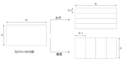
イントラサブパーティション(Intra Sub Partitions、ISP)ツールは、ブロックサイズに応じて、ルマ・イントラ予測ブロックを垂直方向または水平方向に2つまたは4つのサブパーティションへと分割する。例えば、ISPの最小ブロックサイズは4×8(または8×4)である。ブロックサイズが4×8(または8×4)を超える場合、対応するブロックは、4つのサブパーティションで分割される。図5は、2つの可能性の例を示している。全てのサブパーティションは、16サンプル以上を有することの条件を満たしている。
2.4 Intra subpartition (ISP)
The Intra Sub Partitions (ISP) tool divides the luma intra prediction block vertically or horizontally into two or four subpartitions, depending on the block size. For example, the minimum block size for ISPs is 4×8 (or 8×4). If the block size exceeds 4×8 (or 8×4), the corresponding block is divided into four subpartitions. Figure 5 shows an example of two possibilities. All subpartitions satisfy the condition of having 16 or more samples.
各サブパーティションについて、再構成されたサンプルは、予測信号に残留信号を加えることによって獲得される。ここで、残留信号は、エントロピーデコーディング、逆量子化、および逆変換といったプロセスによって生成される。従って、各サブパーティションの再構成されたサンプル値は、次のサブパーティションの予測を生成するために利用可能であり、そして、各サブパーティションは繰り返し処理される。加えて、処理される第1サブパーティションは、CUの左上のサンプルを含んでおり、そして、次いで、下向き(水平分割)または右向き(垂直分割)に続いている。その結果として、サブパーティション予測信号を生成するために使用される参照サンプル(reference sample)は、ラインの左側および上方にのみ配置される。全てのサブパーティションは、同じイントラモードを共有する。 For each subpartition, reconstructed samples are obtained by adding the residual signal to the predicted signal. Here, the residual signal is generated by processes such as entropy decoding , inverse quantization, and inverse transformation. Therefore, the reconstructed sample values of each subpartition are available to generate predictions for the next subpartition, and each subpartition is iterated. In addition, the first sub-partition to be processed includes the top left sample of the CU, and then continues downwards (horizontal split) or to the right (vertical split). As a result, the reference samples used to generate the subpartition prediction signal are placed only to the left and above the line. All subpartitions share the same intra mode.
2.5 アフィン線形加重イントラ予測(ALWIPまたはマトリクスベースのイントラ予測)
アフィン線形加重イントラ予測(Affine linear weighted intra prediction、ALWIP、別名マトリクスベースイントラ予測(MIP))が、JVET‐N0217において提案されている。
2.5 Affine linear weighted intra prediction (ALWIP or matrix-based intra prediction)
Affine linear weighted intra prediction (ALWIP, also known as matrix-based intra prediction (MIP)) is proposed in JVET-N0217.
JVET-N0217では、2つの試験が実施される。テスト1において、ALWIPは、8Kバイトのメモリ制限およびサンプル当たり最大4乗算で設計されている。テスト2はテスト1と同様であるが、さらに、メモリ要求およびモデルアーキテクチャの観点から設計を単純化している。
Two tests will be conducted in JVET-N0217. In test 1, ALWIP is designed with a memory limit of 8K bytes and a maximum of 4 multiplications per sample.
- 全てのブロック形状に対する行列およびオフセットベクトルの単一セット - Single set of matrices and offset vectors for all block shapes
- 全てのブロック形状についてモードの数を19まで削減 - Reduced number of modes to 19 for all block shapes
- メモリ要求を5760の10ビット値、すなわち7.20キロバイトまで削減 - Reduced memory requirements to 5760 10-bit values, or 7.20 kilobytes
-予測されたサンプルの線形補間を、第1テストのように、反復補間を置き換えて、方向ごとに単一ステップで実行 - Linear interpolation of the predicted samples is performed in a single step per direction, replacing iterative interpolation, as in the first test.
2.5.12.5.1JVET-N0217試験1
幅Wおよび高Hの矩形ブロックのサンプルを予測するために、アフィン線形加重イントラ予測(ALWIP)は、入力として、ブロックの左の再構成隣接境界サンプルの1つのラインHと、ブロックの上の再構成隣接境界サンプルの1つのラインWをとる。再構成されたサンプルが利用可能でない場合は、従来のイントラ予測と同様に生成される。
予測信号の生成は、次の3個のステップに基づいている。
2.5.12.5.1JVET-N0217 Exam 1
To predict samples of a rectangular block of width W and height H, affine linear weighted intra prediction (ALWIP) takes as input one line H of the reconstructed neighboring boundary samples to the left of the block and the reconstructed adjacent boundary samples above the block. Take one line W of the constituent adjacent boundary samples. If reconstructed samples are not available, they are generated similarly to traditional intra prediction.
The generation of the predicted signal is based on the following three steps.
境界サンプルから、W=H=4の場合には4個のサンプル、および、他の全ての場合には8個のサンプルが平均化によって抽出される。 From the boundary samples, 4 samples are extracted in the case W=H=4 and 8 samples in all other cases by averaging.
入力として平均化されたサンプルを用いて、行列ベクトル乗算が実行され、オフセットの加算がその後に続く。その結果、元の(original)ブロック内のサンプルのサブサンプリングされたセットについて減少した予測信号が得られる。 Using the averaged samples as input, matrix-vector multiplication is performed, followed by addition of offsets. The result is a reduced predicted signal for the subsampled set of samples within the original block.
残りの位置での予測信号は、各方向における単一ステップ線形補間である線形補間によるサブサンプリングされたセットに対する予測信号から生成される。 The predicted signals at the remaining positions are generated from the predicted signals for the subsampled set by linear interpolation, which is a single step linear interpolation in each direction.
予測信号を生成するために必要なマトリクスおよびオフセットベクトルは、マトリクスの3個の集合(set)S0、S1、S2から得られる。集合S0は、それぞれが16個の行と4個の列を有する18個のマトリクスAi
0、i∈{0,...,17}と、それぞれがサイズ16の18個のオフセットベクトルbi
0、i∈{0,...,17}から構成されている。その集合のマトリクスおよびオフセットベクトルは、サイズ4×4のブロックについて使用される。集合S1は、それぞれが16個の行と8個の列を有する、10個のマトリクスAi
1、i∈{0,...,9}と、それぞれがサイズ16の10個のオフセットベクトルbi
1、i∈{0,...,9}から構成されている。その集合のマトリクスおよびオフセットベクトルは、サイズ4×8、8×4、および8×8のブロックに使用される。最後に、集合S2は、それぞれが64個の行と8個の列を有する6個のマトリクスAi
2、i∈{0,...,5}と、サイズ16の6個のオフセットベクトルbi
2、i∈{0,...,5}から構成されている。その集合のマトリクスおよびオフセットベクトル、または、これらのマトリクスの一部およびオフセットベクトルは、他の全てのブロック形状に使用される。
The matrices and offset vectors needed to generate the prediction signal are obtained from three sets of matrices S 0 , S 1 , S 2 . The set S 0 consists of 18 matrices A i 0 , i∈{0, . . . each having 16 rows and 4 columns. .. .. , 17} and 18 offset vectors b i 0 , i∈{0, . .. .. , 17}. The set matrix and offset vector are used for blocks of size 4x4. The set S 1 consists of 10 matrices A i 1 , i∈{0, . . . each having 16 rows and 8 columns. .. .. , 9} and 10 offset vectors b i 1 , i∈{0, . .. .. , 9}. The set matrix and offset vectors are used for blocks of size 4x8, 8x4, and 8x8. Finally, the set S 2 consists of 6 matrices A i 2 , i∈{0, . . . each with 64 rows and 8 columns. .. .. , 5} and six offset vectors b i 2 of
行列ベクトル積の計算に必要とされる乗算の総数は、常に、4×W×H以下である。言い換えれば、ALWIPモードについて、サンプル当たり最大4回の乗算が必要とされる。 The total number of multiplications required to compute a matrix-vector product is always less than or equal to 4×W×H. In other words, for ALWIP mode, up to 4 multiplications per sample are required.
2.5.2境界の平均化
第1ステップにおいて、入力境界bdrytopおよびbdryleftが、より小さい境界bdrytop
redおよびbdryleft
redに縮小される。ここで、bdrytop
redおよびbdryleft
redは、4×4ブロックの場合は両方とも2個のサンプルで構成され、そして、他の全ての場合は両方とも4個のサンプルで構成される。
2.5.2 Boundary Averaging In the first step, the input boundaries bdry top and bdry left are reduced to smaller boundaries bdry top red and bdry left red . Here, bdry top red and bdry left red are both composed of 2 samples in the case of a 4x4 block, and both composed of 4 samples in all other cases.
4×4ブロックの場合、0≦i<2について、以下を定義する。

そして、bdryleft redを類似的に定義する。 Then, bdry left red is defined analogously.
そうでなければ、ブロック幅Wが、W=4・2kとして与えられる場合、0≦i<4について、以下を定義する。

そして、bdryleft redを類似的に定義する。 Then, bdry left red is defined analogously.
2つの縮小された境界bdrytop
redおよびbdryleft
redは、縮小された境界ベクトルbdryredに連結され、それは、形状4×4のブロックに対してはサイズ4であり、そして、他の全ての形状のブロックに対してはサイズ8である。ALWIPモードを参照する場合、この連結(concatenation)は、以下のように定義される。
The two reduced boundaries bdry top red and bdry left red are concatenated into the reduced boundary vector bdry red , which is of

最後に、サブサンプル予測信号の補間のために、大きなブロックにおいて、平均化境界の第2バージョンが必要とされる。つまり、min(W,H)>8かつW≧Hである場合、W=8*2lであり、0≦i<8について、以下を定義する。

min(W,H)>8かつH>Wである場合、bdryleft redIIを類似的に定義する。 Analogously define bdry left redII if min(W,H)>8 and H>W.
2.5.3 行列ベクトル乗算による縮小予測信号の生成
縮小入力ベクトルbdryredから、縮小予測信号predredを生成する。後者の信号は、幅Wredおよび高さHredのダウンサンプルブロック上の信号である。ここで、WredおよびHredは、以下のように定義される。
2.5.3 Generation of reduced prediction signal by matrix-vector multiplication A reduced prediction signal pred red is generated from the reduced input vector bdry red . The latter signal is the signal on the downsample block of width W red and height H red . Here, W red and H red are defined as follows.


縮小予測信号predredは、行列ベクトル積を計算し、かつ、オフセットを加算することによって計算される。 The reduced prediction signal pred red is computed by computing a matrix-vector product and adding an offset.
predred=A・bdryred+b pred red =A・bdry red +b
ここでAは、マトリクスであり、Wred・Hred行、および、W=H=4の場合に4列、かつ、他の全ての場合に列を有する。bは、サイズWred・Hredのベクトルである。 Here A is a matrix and has W red H red rows and 4 columns if W=H=4 and columns in all other cases. b is a vector of size W red H red .
マトリクスAおよびベクトルbは、集合S0、S1、S2のうち1つから、以下のように得られる。インデックスidx=idx(W,H)を以下のように定義する。 Matrix A and vector b are obtained from one of the sets S 0 , S 1 , S 2 as follows. Index idx=idx(W,H) is defined as follows.

さらに、mを以下のように置く。 Furthermore, set m as follows.

次いで、idx≦1またはidx=2、かつ、min(W,H)>4である場合に、A=Am
idxかつb=bm
idxである。idx=2、かつ、min(W,H)=4である場合に、A=Am
idxかつb=bm
idxである。
idx=2、かつ、min(W,H)=4である場合には、Aを、Am
idxの全ての行を除外することによって生じる行列とする。W=4である場合には、Aを、ダウンサンプリングされたブロック内の奇数のx座標に対応する行列とし、もしくは、H=4である場合には、Aを、ダウンサンプリングされたブロック内の奇数のy座標に対応する行列とする。
Then, if idx≦1 or idx=2 and min(W,H)>4, then A=A m idx and b=b m idx . If idx=2 and min(W,H)=4, then A=A m idx and b=b m idx .
If idx=2 and min(W,H)=4, let A be the matrix resulting from excluding all rows of A m idx . If W=4, let A be the matrix corresponding to the odd x-coordinates in the downsampled block, or if H=4, let A be the matrix corresponding to the odd x-coordinates in the downsampled block. Let it be a matrix corresponding to odd-numbered y-coordinates.
最終的に、以下の場合には、縮小された予測シグナルが、その転置(transpose)で置き換えられる。 Finally, the reduced prediction signal is replaced by its transpose if:
- W=H=4、かつ、mode≧18 - W=H=4 and mode≧18
- max(W,H)=8、かつ、mode≧10 - max(W,H)=8 and mode≧10
- max(W,H)>8、かつ、mode≧6 - max(W,H)>8 and mode≧6
predredの計算に必要な乗法の数は、W=H=4である場合には4である。この場合に、Aは、4列および16行を有するからである。他の全ての場合において、Aは、8列およびWred・Hred個の行を有し、そして、これらの場合には、8・Wred・Hred≦4・W・Hの乗算必要であることを直ちに検証する。すなわち、これらの場合においても、predredを計算するために、1サンプル当たり最大4乗算が必要とされる。 The number of multiplications required to calculate pred red is 4 if W=H=4. This is because in this case A has 4 columns and 16 rows. In all other cases, A has 8 columns and W red H red rows, and in these cases 8 W red H red ≦4 W H multiplications are required. Verify something immediately. That is, even in these cases, a maximum of 4 multiplications per sample are required to calculate pred red .
2.5.4 ALWIPプロセス全体の説明図
平均化、行列ベクトル乗算、および線形補間の全プロセスが、図6-図9における異なる形状について示されている。残りの形状は、図示のケースの1つと同様に扱われることに注意されたい。
2.5.4 Illustration of the entire ALWIP process The entire process of averaging, matrix-vector multiplication, and linear interpolation is illustrated for different shapes in Figures 6-9. Note that the remaining shapes are treated similarly to one of the illustrated cases.
1. 4×4ブロックが与えられた場合、ALWIPは、境界の各軸に沿って2つの平均をとる。結果として生じる4個の入力サンプルは、行列ベクトル乗算に入る。マトリクスは、集合S0からとられる。オフセットを加えた後で、このことは、16個の最終予測サンプルを生じる。予測信号を生成するために、線形補間は必要でない。従って、サンプル当たり合計(4・16)/(4・4)=4回の乗算が実行される。 1. Given a 4x4 block, ALWIP takes two averages along each axis of the boundary. The resulting four input samples go into matrix-vector multiplication. The matrix is taken from the set S0 . After adding the offset, this results in 16 final predicted samples. No linear interpolation is required to generate the predicted signal. Therefore, a total of (4·16)/(4·4)=4 multiplications are performed per sample.
2. 8×8ブロックが与えられた場合、ALWIPは境界の各軸に沿って4つの平均をとる。結果として生じる8個の入力サンプルは、行列ベクトル乗算に入る。マトリクスは、集合S1からとられる。このことは、予測ブロックの奇数位置に16個のサンプルを生じる。従って、サンプル当たり合計(8・16)/(8・8)=2回の乗算が実行される。オフセットを加えた後で、これらのサンプルは、縮小された上部境界を使用することによって垂直に補間される。水平補間が、元の左側の境界を使用することによって続く。 2. Given an 8x8 block, ALWIP takes four averages along each axis of the boundary. The resulting 8 input samples go into matrix-vector multiplication. The matrix is taken from the set S1 . This results in 16 samples in odd positions of the prediction block. Therefore, a total of (8·16)/(8·8)=2 multiplications are performed per sample. After adding the offset, these samples are interpolated vertically by using the reduced top boundary. Horizontal interpolation follows by using the original left border.
3. 8×4ブロックが与えられた場合、ALWIPは境界の水平軸に沿って4つの平均、および、左側境界の4つの元の境界値をとる。結果として生じる8個の入力サンプルは、行列ベクトル乗算に入る。マトリクスは、集合S1からとられる。このことは、予測ブロックの奇数の水平位置および各垂直位置に16個のサンプルを生じる。従って、サンプル当たり合計(8・16)/(8・4)=4回の乗算が実行される。オフセットを加えた後で、これらのサンプルは、元の左側境界を使用して水平方向に補間される。 3. Given an 8x4 block, ALWIP takes the four averages along the horizontal axis of the border and the four original border values on the left border. The resulting 8 input samples go into matrix-vector multiplication. The matrix is taken from the set S1 . This results in 16 samples at odd horizontal positions and each vertical position of the prediction block. Therefore, a total of (8·16)/(8·4)=4 multiplications are performed per sample. After adding the offset, these samples are interpolated horizontally using the original left boundary.
4. 16×16ブロックが与えられた場合、ALWIPは境界の各軸に沿って4つの平均をとる。結果として生じる8個の入力サンプルは、行列ベクトル乗算に入る。マトリクスは、集合S2からとられる。このことは、予測ブロックの奇数位置に64個のサンプルを生じる。従って、サンプル当たり合計(8・64)/(16・16)=2回の乗算が実行される。オフセットを加えた後で、これらのサンプルは、上部境界の8個の平均を使用することにより垂直方向に補間される。水平補間が、元の左側境界を使用することにより後に続く。補間処理は、この場合、いかなる乗法も追加しない。従って、全体として、ALWIP予測を計算するためには、サンプル当たり2回の乗算が必要とされる。 4. Given a 16x16 block, ALWIP takes four averages along each axis of the boundary. The resulting 8 input samples go into matrix-vector multiplication. The matrix is taken from the set S2 . This results in 64 samples in odd positions of the prediction block. Therefore, a total of (8·64)/(16·16)=2 multiplications are performed per sample. After adding the offset, these samples are interpolated vertically by using the average of the 8 top boundaries. Horizontal interpolation follows by using the original left border. The interpolation process does not add any multiplication in this case. Therefore, in total, two multiplications per sample are required to calculate the ALWIP prediction.
より大きな形状について、手順は本質的に同じであり、かつ、サンプル当たりの乗算数が4未満であることをチェックすることは容易である。 For larger shapes, the procedure is essentially the same and it is easy to check that the number of multiplications per sample is less than 4.
W>8であるW×8ブロックについては、サンプルが奇数の水平位置および各垂直位置で与えられるので、水平補間のみが必要である。 For W>8 blocks, only horizontal interpolation is required since samples are provided at an odd number of horizontal positions and at each vertical position.
最後に、W>8であるW×4ブロックについて、A_kbeは、ダウンサンプリングされたブロックの水平に沿った奇数エントリに対応する各行を除外することによって生じる行列とする。従って、出力サイズは32であり、そして、再び、水平補間のみが実行されるように残る。 Finally, for a W×4 block with W>8, let A_kbe be the matrix resulting from excluding each row corresponding to an odd entry along the horizontal of the downsampled block. Therefore, the output size is 32, and again only horizontal interpolation remains to be performed.
転置された場合は、それに応じて取り扱われる。 If transposed, it will be treated accordingly.
2.5.5 単一ステップ線形補間
max(W,H)≧8であるW×Hブロックについて、予測信号は、線形補間によるWred×Hredに対する縮小予測信号predredから生じる。ブロックの形状に応じて、垂直方向、水平方向、または、両方向において線形補間が実行される。線形補間が両方向に適用される場合には、W<Hであれば、水平方向において最初に適用され、そして、それ以外であれば、垂直方向において最初に適用される。
2.5.5 Single-Step Linear Interpolation For W×H blocks with max(W,H)≧8, the prediction signal results from the reduced prediction signal pred red for W red ×H red by linear interpolation. Depending on the shape of the block, linear interpolation is performed in the vertical direction, horizontal direction, or both directions. If linear interpolation is applied in both directions, it is applied first in the horizontal direction if W<H, and first in the vertical direction otherwise.
一般性を損なうことなく、max(W,H)≧8であり、かつ、W≧HであるW×Hブロックを考慮する。次いで、一次元線形補間が以下のように実行される。一般性を損なうことなく、垂直方向における線形補間を説明することで十分である。最初に、縮小予測信号が、境界信号によって先頭(top)まで拡張される。垂直のアップサンプリング係数Uver=H/Hredを定義し、かつ、Uver=2Uverを書き込む。次に、以下のように拡張縮小予測信号を定義する。 Without loss of generality, consider a W×H block where max(W,H)≧8 and W≧H. One-dimensional linear interpolation is then performed as follows. Without loss of generality, it is sufficient to describe linear interpolation in the vertical direction. First, the reduced prediction signal is extended to the top by a boundary signal. Define the vertical upsampling coefficient U ver =H/H red and write U ver =2 U ver . Next, the expanded/reduced prediction signal is defined as follows.

次いで、この拡張された縮小予測信号から、垂直線形補間予測信号が、以下によって生成される。 A vertical linear interpolation prediction signal is then generated from this extended reduced prediction signal by:
predups,ver red[x][Uver・y+k]=((Uver―k-1)・predred[x][y-1]+(k+1)・predred[x][y]+Uver/2)>>uver pred ups, ver red [x] [U ver・y+k]=((U ver −k−1)・pred red [x][y−1]+(k+1)・pred red [x][y]+U ver /2) >> u ver
ここで、0≦x<Wred、0≦y<Hred、および、0≦k<Uver Here, 0≦x<W red , 0≦y<H red , and 0≦k<U ver
2.5.6 提案されるイントラ予測モードの信号化
イントラモードにおける各コーディングユニット(CU)に対して、ALWIPモードが対応する予測ユニット(PU)に適用されるか否かを示しているフラグがビットストリームで送信される。後者のインデックスの信号化は、JVET-M0043と同様にMRLと調和している。ALWIPモードを適用する場合、ALWIPモードのインデックスpredmodeは、3MPMSでMPM-listを使用して信号化される。
2.5.6 Signaling of the proposed intra prediction mode For each coding unit (CU) in intra mode, a flag indicating whether ALWIP mode is applied to the corresponding prediction unit (PU) is added to the bitstream. Sent in The latter index signaling is harmonized with MRL as in JVET-M0043. When applying ALWIP mode, the ALWIP mode index predmode is signaled using MPM-list in 3MPMS.
ここで、MPMの導出は、以下のように、上および左PUのイントラモードを使用して実行される。従来のイントラ予測モードpredmodeAngularにALWIPモードを割り当てる、3つの固定テーブルが存在する。
map_angular_to_alwipidx,idx∈{0,1,2}
Here, the derivation of the MPM is performed using the intra mode of the top and left PUs as follows. Traditional Intra Prediction Mode predmode There are three fixed tables that assign ALWIP modes to Angular .
map_angular_to_alwip idx , idx∈{0,1,2}
predmodeALWIP=map_angular_to_alwipidx[predmodeAngular] predmode ALWIP =map_angular_to_alwip idx [predmode Angular ]
幅Wおよび高さHの各PUに対して、インデックスを定義する。 Define an index for each PU with width W and height H.
idx(PU)=idx(W,H)∈{0,1,2} idx(PU)=idx(W,H)∈{0,1,2}
セクション2.5.3のように、3個のセットのうちどれからALWIP-parametersがとられるかを示す。 As in Section 2.5.3, it indicates which of the three sets the ALWIP-parameters are taken from.
上の予測ユニットUnitaboveが利用可能であり、現在PUと同じCTUに属し、かつ、イントラモードにある場合、idx(PU)=idx(PUabove)、かつ、ALWIPがPUaboveにALWIPモードpredmodeabove ALWIPで適用される場合には、以下を置く。 If the above prediction unit Unit above is available, currently belongs to the same CTU as the PU, and is in intra mode, idx(PU) = idx(PU above ), and ALWIP changes to PU above ALWIP mode predmode above When applied in ALWIP , place the following:
modeabove ALWIP=predmodeabove ALWIP mode above ALWIP =predmode above ALWIP
上PUが利用可能であり、現在PUと同じCTUに属し、かつ、イントラモードにある場合、そして、従来のイントラ予測モードpredmodeabove Angularが上PUに適用される場合には、以下を置く。 If the upper PU is available, currently belongs to the same CTU as the PU, and is in intra mode, and the conventional intra prediction mode predmode above Angular is applied to the upper PU, put the following:
modeabove ALWIP=map_angular_to_alwipidx(PUabove)[predmodeabove Angular] mode above ALWIP =map_angular_to_alwip idx(PUabove) [predmode above Angular ]
他の全ての場合においては、以下を置く。 In all other cases, put the following:
modeabove ALWIP=-1 mode above ALWIP =-1
それは、このモードが利用可能でないことを意味している。同様にして、しかし、左PUが現在PUと同じCTUに所属する必要があるという制約なしに、modeleft ALWIPモードを導出する。 That means this mode is not available. Similarly, derive the mode left ALWIP mode, but without the constraint that the left PU needs to belong to the same CTU as the current PU.
最終的に、3個の固定デフォルトリストlistidx,idx∈{0,1,2}が提供され、それぞれが3個の異なるALWIPモードを含んでいる。デフォルトリストlistidx(PU)、および、modeabove ALWIPとmodeleft ALWIPから、デフォルト値を-1に置き換え、かつ、繰り返しを省略することによって、3個の別個のMPMを構成する。 Finally, three fixed default lists list idx , idx∈{0,1,2} are provided, each containing three different ALWIP modes. From the default list list idx(PU) and mode above ALWIP and mode left ALWIP , construct three separate MPMs by replacing the default value with -1 and omitting the repeat.
ALWIP MPMリスト構成で使用される左隣接ブロックおよび上隣接ブロックは、図10に示されるようにA1およびB1である。 The left neighbor block and top neighbor block used in the ALWIP MPM list configuration are A1 and B1 as shown in FIG. 10.
2.5.7 従来のルマおよびクロマイントラ予測モードのための適応MPMリスト導出
提案されるALWIPモードは、従来のイントラ予測モードのMPMベースコーディングと以下のように調和されている。従来のイントラ予測モードのためのルマおよびクロマMPMリスト導出プロセスは、固定テーブルmap_alwip_to_angularidx,idx∈{0,1,2}を使用し、所与のPU上のALWIPモードpremodeALWIPを従来のイントラ予測モードの1つにマッピングする。
2.5.7 Adaptive MPM List Derivation for Traditional Luma and Chroma Intra Prediction Modes The proposed ALWIP mode is harmonized with the MPM-based coding of traditional intra prediction modes as follows. The luma and chroma MPM list derivation process for traditional intra prediction mode uses fixed table map_alwip_to_angular idx , idx∈ {0,1,2} Map to one of the modes.
premodeAngular=map_alwip_to_angularidx(PU)[premodeALWIP] premode Angular =map_alwip_to_angular idx(PU) [premode ALWIP ]
ルマMPMリストの導出では、ALWIPモードpremodeALWIPを使用する隣接ルマブロックに遭遇するときはいつでも、このブロックが、従来のイントラ予測モードpremodeAngularを使用しているかのように扱われる。クロマMPMリストの導出では、現在ルマブロックがLWIPモードを使用するときはいつでも、ALWIPモードを従来のイントラ予測モードに変換するために同じマッピングが使用される。 In the derivation of the luma MPM list, whenever a neighboring luma block using the ALWIP mode premode ALWIP is encountered, this block is treated as if it were using the conventional intra prediction mode premode Angular . In the derivation of the chroma MPM list, the same mapping is used to convert the ALWIP mode to the conventional intra-prediction mode whenever the luma block currently uses the LWIP mode.
2.5.8 対応する修正された作業原案
いくつかの実施態様においては、このセクションで説明されるように、開示される技術の実施形態に基づいて、intra_lwip_flag、intra_lwip_mpm_flag、intra_lwip_mpm_idx、およびintra_lwip_mpm_lesterに関する部分が作業原案に追加されている。
2.5.8 Corresponding Revised Working Draft In some implementations, portions relating to intra_lwip_flag, intra_lwip_mpm_flag, intra_lwip_mpm_idx, and intra_lwip_mpm_lester are modified based on embodiments of the disclosed technology, as described in this section. Added to the original draft.
いくつかの実施態様においては、このセクションで説明されるように、開示される技術の実施態様に基づく作業原案への追加および修正を示すために<begin>タグおよび<end>タグが使用されている。


ALWIPのまとめ
幅Wおよび高さHの矩形ブロックのサンプルを予測するために、アフィン線形加重イントラ予測(ALWIP)は、ブロックの左のH再構成隣接境界サンプルの1ラインと、ブロックの上のW再構成隣接境界サンプルの1ラインを入力としてとる。再構成されたサンプルが利用で可能でない場合は、通常のイントラ予測と同様に生成される。ALWIPは、ルマイントラブロックにのみ適用される。クロマイントラブロックに対しては、従来のイントラコーディングモードが適用される。
Summary of ALWIP To predict samples of a rectangular block of width W and height H, affine linear weighted intra prediction (ALWIP) uses one line of H reconstructed adjacent boundary samples to the left of the block and W Take one line of reconstructed adjacent boundary samples as input. If reconstructed samples are not available, they are generated similarly to normal intra prediction. ALWIP applies only to Luma Intra blocks. For chroma intra blocks, conventional intra coding mode is applied.
予測信号の生成は、次の3個のステップに基づいている The generation of the predicted signal is based on the following three steps:
1.境界サンプルのうち,W=H=4の場合は4サンプル、および、それ以外の場合は8サンプルが平均化によって抽出される。 1. Among the boundary samples, 4 samples are extracted when W=H=4, and 8 samples are extracted in other cases by averaging.
2.平均化されたサンプルを入力として使用して、行列ベクトル乗算、その後に続いてオフセットの加算が実行される。その結果、元のブロック中のサブサンプリングされたサンプルのセットについて縮小予測信号が得られる。 2. Matrix-vector multiplication followed by offset addition is performed using the averaged samples as input. As a result, a reduced predicted signal is obtained for the subsampled set of samples in the original block.
3 残りの位置での予測信号は、各方向での単一ステップ線形補間である、線形補間によってサブサンプリングされたセットにおける予測信号から生成される。 3 The predicted signals at the remaining positions are generated from the predicted signals in the subsampled set by linear interpolation, which is a single-step linear interpolation in each direction.
ALWIPモードが適用される場合、ALWIPモードのインデックスは、3MPMSでMPM-listを使用して信号化される。ここで、MPMの導出は、以下のように、上および左PUのイントラモードを使用して実行される。3個の固定テーブルmap_angular_to_alwipidx,idx∈{0,1,2}が存在し、それぞれ従来のイントラ予測モードpredmodeAngularにALWIPモードを割り当てる。 If ALWIP mode is applied, the ALWIP mode index is signaled using MPM-list in 3MPMS. Here, the derivation of the MPM is performed using the intra mode of the top and left PUs as follows. There are three fixed tables map_angular_to_alwip idx , idx∈{0,1,2}, each assigning an ALWIP mode to the conventional intra prediction mode predmode Angular .
predmodeALWIP=map_angular_to_alwipidx[predmodeAngular] predmode ALWIP =map_angular_to_alwip idx [predmode Angular ]
幅Wおよび高さHの各PUに対して、インデックスを定義する。 Define an index for each PU with width W and height H.
idx(PU)=idx(W,H)∈{0,1,2} idx(PU)=idx(W,H)∈{0,1,2}
3個のセットのうちどれからALWIP-parametersがとられるかを示している。 Indicates which of the three sets ALWIP-parameters are taken from.
上の予測ユニットUnitaboveが利用可能であり、現在PUと同じCTUに属し、かつ、イントラモードにある場合、idx(PU)=idx(PUabove)、かつ、ALWIPがPUaboveにALWIPモードpredmodeabove ALWIPで適用される場合には、以下を置く。 If the above prediction unit Unit above is available, currently belongs to the same CTU as PU, and is in intra mode, idx(PU) = idx(PU above ), and ALWIP changes to PU above ALWIP mode predmode above When applied in ALWIP , place the following:
modeabove ALWIP=predmodeabove ALWIP mode above ALWIP = predmode above ALWIP
上PUが利用可能であり、現在PUと同じCTUに属し、かつ、イントラモードにある場合、そして、従来のイントラ予測モードpredmodeabove Angularが上PUに適用される場合には、以下を置く。 If the upper PU is available, currently belongs to the same CTU as the PU, and is in intra mode, and the conventional intra prediction mode predmode above Angular is applied to the upper PU, put the following:
modeabove ALWIP=map_angular_to_alwipidx(PUabove)[predmodeabove Angular] mode above ALWIP =map_angular_to_alwip idx(PUabove) [predmode above Angular ]
他の全ての場合においては、以下を置く。 In all other cases, put the following:
modeabove ALWIP=-1 mode above ALWIP =-1
それは、このモードが利用可能でないことを意味している。同様にして、しかし、左PUが現在PUと同じCTUに所属する必要があるという制約なしに、modeleft ALWIPモードを導出する。 That means this mode is not available. Similarly, derive the mode left ALWIP mode, but without the constraint that the left PU needs to belong to the same CTU as the current PU.
最終的に、3個の固定デフォルトリストlistidx,idx∈{0,1,2}が提供され、それぞれが3個の異なるALWIPモードを含んでいる。デフォルトリストlistidx(PU)、および、modeabove ALWIPとmodeleft ALWIPから、デフォルト値を-1に置き換え、かつ、繰り返しを省略することによって、3個の別個のMPMを構成する。 Finally, three fixed default lists list idx , idx∈{0,1,2} are provided, each containing three different ALWIP modes. From the default list list idx(PU) and mode above ALWIP and mode left ALWIP , construct three separate MPMs by replacing the default value with -1 and omitting the repetition.
ルマMPMリストの導出では、ALWIPモードpremodeALWIPを使用する隣接ルマブロックに遭遇するときはいつでも、このブロックが、従来のイントラ予測モードpremodeAngularを使用しているかのように扱われる。 In the derivation of the luma MPM list, whenever a neighboring luma block using the ALWIP mode premode ALWIP is encountered, this block is treated as if it were using the conventional intra prediction mode premode Angular .
premodeAngular=map_alwip_to_angularidx(PU)[premodeALWIP] premode Angular =map_alwip_to_angular idx(PU) [premode ALWIP ]
3 VVCにおける変換
3.1 多重変換選択(MTS)
HEVCで使用されてきたDCT-IIに加えて、多重変換選択(Multiple Transform Selection、MTS)方式が、インターコーディングコード化ブロックおよびイントラコード化ブロック両方の残留コーディングについて使用される。DCT8/DST7から選択された複数の変換を使用する。新しく導入される変換行列は、DST-VIIおよびDCT-VIIIである。
3 Conversion in VVC
3.1 Multiple transform selection (MTS)
In addition to DCT-II, which has been used in HEVC, a Multiple Transform Selection (MTS) scheme is used for residual coding of both inter- and intra-coded blocks. Use multiple transforms selected from DCT8/DST7. The newly introduced transformation matrices are DST-VII and DCT-VIII.
3.2 JVET-N0193で提案された縮小二次変換(RST)
縮小二次変換(reduced secondary transform、RST)は、4×4および8×8ブロックに対して、それぞれ、16×16および16×64非分離(non-separable)変換を適用する。一次(primary)順変換および逆変換は、なおも、2つの一次元水平/垂直変換パスと同じ方法で実行される。二次順変換および逆変換は、一次変換とは別のプロセスステップである。エンコーダに対しては、一次順変換が最初に実行され、次いで、二次順変換と量子化、およびCABACビットエンコーディングが続く。デコーダに対しては、CABACビットデコーディングおよび逆量子化、次いで、二次逆変換が最初に実行され、次に、一次逆変換が実行される。RSTは、イントラスライスおよびインタースライスの両方においてイントラコード化TUに対してのみ適用される。
3.2 Reduced quadratic transform (RST) proposed in JVET-N0193
The reduced secondary transform (RST) applies 16x16 and 16x64 non-separable transforms to 4x4 and 8x8 blocks, respectively. The primary forward and inverse transforms are still performed in the same way as the two one-dimensional horizontal/vertical transform passes. The quadratic forward and inverse transforms are separate process steps from the linear transform. For the encoder, a first-order forward transform is performed first, followed by a second-order forward transform and quantization, and CABAC bit encoding . For the decoder, CABAC bit decoding and inverse quantization, then the second-order inverse transform is performed first, and then the first-order inverse transform is performed. RST applies only to intra-coded TUs in both intra-slice and inter-slice.
3.3 JVET-N0185におけるイントラモードコーディングのための統一MPM
リスト多重基準線(MRL)およびイントラサブパーティション(ISP)コーディングツールが適用されるか否かに関係なく、イントラブロックに対して統一6MPMリストが提案されている。MPMリストは、VTM4.0のように、隣接するブロックの左および上のイントラモードに基づいて構築される。左のモードがLeftとして示され、かつ、上のブロックのモードがAboveとして示されるとすれば、統一MPMリスト(unified MPM list)は
以下のように構築される。
・ 隣接ブロックが利用可能でない場合、そのイントラモードがデフォルトでプラナー(Planar)に対して設定される。
・ LeftモードおよびAboveモードの両方が非角度(non-angular)モードである場合:
a. MPMリスト→{Planar,C,V,H,V-4,V+4}
・ LeftモードおよびAboveモードのうち一方が角度モードであり、かつ、他方が非角度モードである場合:
a. モードMaxをLeftおよびAbove内のより大きなモードとして設定する。
b. MPMリスト→{Planar,Max,DC,Max-1,Max+1,Max-2}
・ LeftモードおよびAboveモードの両方が角度モードであり、かつ、それらが異なる場合:
a. モードMaxをLeftおよびAbove内のより大きなモードとして設定する。
b. LeftモードとAboveモードの差異が2-62の範囲である場合、
i. MPMリスト→{Planar,Left,Above,DC,Max-1,Max+1}
c.それ以外の場合、
i. MPMリスト→{Planar,Left,Above,DC,Max-2,Max+2}
・ LeftモードおよびAboveモードの両方が角度モードであり、かつ、それらが同じである場合:
a. MPMリスト→{Planar,Left,Left-1,Left+1,DC,Left-2}
3.3 Unified MPM for intra mode coding in JVET-N0185
A unified 6MPM list is proposed for intra blocks, regardless of whether list multiple baseline (MRL) and intra subpartition (ISP) coding tools are applied. The MPM list is constructed based on intra modes to the left and above of adjacent blocks, like in VTM4.0. If the left mode is denoted as Left and the mode of the upper block is denoted as Above, the unified MPM list is constructed as follows.
- If a neighboring block is not available, its intra mode defaults to Planar.
- If both Left mode and Above mode are non-angular modes:
a. MPM list → {Planar,C,V,H,V-4,V+4}
- If one of Left mode and Above mode is angular mode and the other is non-angular mode:
a. Set mode Max as the larger mode within Left and Above.
b. MPM list → {Planar,Max,DC,Max-1,Max+1,Max-2}
- If both Left mode and Above mode are angular modes and they are different:
a. Set mode Max as the larger mode within Left and Above.
b. If the difference between Left mode and Above mode is in the range 2-62,
i. MPM list → {Planar,Left,Above,DC,Max-1,Max+1}
c. Otherwise,
i. MPM list → {Planar,Left,Above,DC,Max-2,Max+2}
- If Left mode and Above mode are both angular modes and they are the same:
a. MPM list → {Planar,Left,Left-1,Left+1,DC,Left-2}
さらに、MPMインデックスコードワードの第1ビンは、CABACコンテキストコード化されている。合計3個のコンテキストが使用され、現在のイントラブロックがMRLイネーブルであるか、ISPイネーブルであるか、または、通常のイントラブロックであるかに対応している。 Furthermore, the first bin of the MPM index codeword is CABAC context coded. A total of three contexts are used, corresponding to whether the current intra block is MRL enabled, ISP enabled, or a regular intra block.
統一MPMリスト構成で使用される左隣接ブロックおよび上隣接ブロックは、図10で示されるようにA2およびB2である。 The left neighbor block and top neighbor block used in the unified MPM list configuration are A2 and B2 as shown in FIG. 10.
1つのMPMフラグが最初にコード化される。ブロックがMPMリスト内のモードのうちの1つでコード化されている場合、MPMインデックスが、さらにコード化される。そうでなければ、残りのモードのインデックス(MPMを除く)がコード化される。 One MPM flag is encoded first. If the block is coded with one of the modes in the MPM list, the MPM index is also coded. Otherwise, the remaining mode indices (excluding MPM) are encoded.
4 既存の実装における欠点の例
JVET-N0217におけるALWIPの設計は、以下の問題を有している。
4 Examples of shortcomings in existing implementations
The ALWIP design in JVET-N0217 has the following problems.
1)2019年3月のJVETミーティングでは、MRLモード、ISPモード、通常のイントラモードについて、統一6MPMリスト(unified 6-MPM list)生成が採用された。しかし、アフィン線形加重予測モードは、異なる3MPMリスト構成を使用し、MPMリスト構成を複雑にしている。複雑なMPMリスト構成は、特に4×4サンプルといった小さなブロックについて、デコーダのスループットを妥協することがある。 1) At the JVET meeting in March 2019, unified 6-MPM list generation was adopted for MRL mode, ISP mode, and normal intra mode. However, the affine linear weighted prediction mode uses a different 3 MPM list structure, which complicates the MPM list structure. Complex MPM list construction can compromise decoder throughput, especially for small blocks such as 4x4 samples.
2)ALWIPは、ブロックのルマコンポーネントにのみ適用される。ALWPコード化ブロックのクロマ成分については、クロマモードインデックスがコード化され、そして、デコーダに送信される。これは、不必要な信号化を生じ得る。 2) ALWIP applies only to the block's luma component. For the chroma component of the ALWP coded block, a chroma mode index is encoded and sent to the decoder. This may result in unnecessary signaling.
3)ALWIPと他のコーディングツールとの相互作用が考慮されるべきである。 3) Interaction between ALWIP and other coding tools should be considered.
4)upsBdryXを以下のように計算する場合、
upsBdryX[x]=(
![]()
Log2(uDwn)-1が-1に等しく、かつ、-1の左シフトが定義されていない可能性がある。
4) If you calculate upsBdryX as below,
upsBdryX[x]=(
![]()
It is possible that Log2(uDwn)-1 is equal to -1 and a left shift of -1 is not defined.
5) 予測サンプルをアップサンプリングする場合に、丸め(rounding)は適用されない。 5) No rounding is applied when upsampling the prediction samples.
6)デブロッキングプロセスにおいて、ALWIPコード化ブロックは、通常のイントラブロックとして扱われる。 6) In the deblocking process, ALWIP coded blocks are treated as normal intra blocks.
5 マトリクスベースのイントラコーディングのための例示的な方法
本開示の技術の実施形態は、既存の実施形態の欠点を克服し、それにより、より高い符号化効率を有するが、計算量はより少ない、ビデオコーディングを提供する。ビデオコーディングのためのマトリクスベースのイントラ予測法は、本文書で説明されるように、既存および将来のビデオコーディング規格の両方を向上させる可能性があり、種々の実装について説明されている以下の実施例において解明されている。以下に提供される、開示される技術の例は、一般的な概念を説明するものであり、限定的なものとして解釈されることを意図するものではない。一つの例においては、明示的に反対に示されない限り、これらの実施例に説明される種々の特徴を組み合わせることができる。
5 Exemplary Method for Matrix-Based Intra- Coding Embodiments of the disclosed technology overcome the shortcomings of existing embodiments, thereby having higher coding efficiency but less computational complexity. Provide video coding . Matrix-based intra-prediction methods for video coding , as described in this document, have the potential to improve both existing and future video coding standards, and various implementations are described below. It is elucidated in the example. The examples of the disclosed technology provided below are illustrative of general concepts and are not intended to be construed as limiting. In one example, various features described in these embodiments may be combined, unless explicitly indicated to the contrary.
以下の説明において、イントラ予測モードは、角度イントラ予測モード(DC、プラナー、CCLM、および、他の可能なイントラ予測モードを含む)を指し、そして、イントラモードは、通常(normal)のイントラモード、またはMRL、もしくは、ISPまたはALWIPを指す。 In the following description, intra prediction mode refers to angular intra prediction mode (including DC, planar, CCLM, and other possible intra prediction modes), and intra prediction mode refers to normal intra prediction mode, or MRL, or ISP or ALWIP.
以下の説明において、「他のイントラモード(“other intra modes”)」とは、通常のイントラモード、またはMRL、もしくはISPといった、ALWIP以外の1つまたは複数のイントラモードを指す。 In the following description, "other intra modes" refers to one or more intra modes other than ALWIP, such as normal intra mode, MRL, or ISP.
以下の説明において、SatShift(x,n)は以下のように定義される。 In the following explanation, SatShift(x,n) is defined as follows.

Shift(x,n)は、Shift(x,n)=(x+offset0)>>nとして定義される。 Shift(x,n) is defined as Shift(x,n)=(x+offset0)>>n.
一つの例において、offset0及び/又はoffset1は、(1<<n)>>1または(1<<(n-1))に設定される。別の例において、offset0及び/又はoffset1は、0に設定される。 In one example, offset0 and/or offset1 are set to (1<<n)>>1 or (1<<(n-1)). In another example, offset0 and/or offset1 are set to 0.
別の例においては、offset0=offset1=((1<n)>>1)-1または(1<(n-1))-1である。 In another example, offset0=offset1=((1<n)>>1)-1 or (1<(n-1))-1.
Clip3(min,max,x)は、以下のように定義される。

ALWIPのMPMリスト構成
1. ALWIP用のMPMリストの全部または一部は、非ALWIPイントラモード(通常イントラモード、MRL、ISPなど)用のMPMリストを構築するために、全部または一部の手順に従って構築することが提案されている。
a. 一つの例において、ALWIP用のMPMリストのサイズは、非ALWIPイントラモードのMPMリストのサイズと同じにすることができる。
i. 例えば、ALWIPモードと非ALWIPイントラモードの両方で、MPMリストのサイズは6である。
b. 一つの例において、ALWIPのためのMPMリストは、非ALWIPイントラモードに対するMPMリストから導出することができる。
i. 一つの例において、非ALWIPイントラモードに対するMPMリストを最初に構築することができる。その後、それらの一部または全部をMPMに変換することができ、これをさらにALWIPコード化ブロックのMPMリストに追加することができる。
1) 代わりに、また、ALWIPコード化ブロックのMPMリストに変換したMPMを追加する場合には、剪定を適用してもよい。
2) デフォルトモードは、ALWIPコード化ブロックのMPMリストに追加することができる。
a.一つの例において、デフォルトモードを、非ALWIPイントラモードのMPMリストから変換される前に追加することができる。
b.代わりに、非ALWIPイントラモードのMPMリストから変換した後にデフォルトモードを追加することもできる。
c.代わりに、デフォルトモードを、非ALWIPイントラモードのMPMリストから変換されたモードとインターリーブ方式で追加することもできる。
d.一つの例において、デフォルトモードは、全ての種類のブロックに対して同一であるように固定することができる。
e.代わりに、デフォルトモードは、隣接ブロックの利用可能性、隣接ブロックのモード情報、ブロック寸法(dimension)のようなコード化情報に従って決定されてもよい。
ii. 一つの例において、非ALWIPイントラモードのMPMリストの1つのイントラ予測モードは、それがALWIPのMPMリストに入れられるときに、対応するALWIPイントラ予測モードに変換され得る。
1) 代わりに、非ALWIPイントラモードのMPMリストの全てのイントラ予測モードは、ALWIPのMPMリストを構築するために使用される前に、対応するALWIPイントラ予測モードに変換されてもよい。
2) 代わりに、全ての候補イントラ予測モード(隣接ブロックからのイントラ予測モードおよびプラナーおよびDCなどのデフォルトイントラ予測モードを含むことができる)は、非ALWIPイントラモードのMPMリストを構築するために使用される前に、非ALWIPイントラモードのMPMリストをさらにALWIPのMPMリストを導出するために使用することができるならば、対応するALWIPイントラ予測モードに変換することができる。
3) 一つの例において、2つの変換されたALWIPイントラ予測モードを比較することができる。
a.ある例では、それらが同じであれば、ALWIPのMPMリストに入れられるのはそれらのうちの1つだけである。
b.ある例では、それらが同じであれば、ALWIP以外のイントラモードでは、そのうちの1つだけをMPMリストに入れることができる。
iii. 一つの例において、非ALWIPイントラモードのMPMリストのSイントラ予測モードのうちのKを、ALWIPモードのMPMリストとして選択することができる。例えば、Kは3に等しく、Sは6に等しい。
1) 一つの例において、非ALWIPイントラモードに対するMPMリストの最初のKイントラ予測モードが、ALWIPモードに対するMPMリストとして選択され得る。
2. ALWIPのためのMPMリストを導出するために使用される1つまたは複数の隣接ブロックが、非ALWIPイントラモード(通常イントラモード、MRL、またはISPなど)のためのMPMリストを導出するために使用され得ることが提案される。
a. 一つの例において、ALWIPのMPMリストを導出するために使用される現在ブロックに残された隣接ブロックは、非ALWIPイントラモードのMPMリストを導出するために使用されるものと同じであるべきである。
i. 現在ブロックの左上隅が(xCb,yCb)で、現在ブロックの幅と高さがWとHであると仮定すると、一つの例において、ALWIPと非ALWIPイントラモードの両方のMPMリストを導出するために使用される左隣接ブロックが位置をカバーすることができる(xCb-1,yCb)。別の例では、ALWIPモードと非ALWIPイントラモードの両方のMPMリストを導出するために使用される左隣接ブロックが、位置(xCb-1、yCb+H-1)をカバーし得る。
ii. 例えば、統一されたMPMリスト構成で使用される左隣接ブロック及び上隣接ブロックは、図10に示されるようにA2及びB2である。
b. 一つの例において、ALWIPのMPMリストを導出するために使用される現在ブロックの上の隣接ブロックは、非ALWIPイントラモードのMPMリストを導出するために使用されるものと同じであるべきである。
i. 現在ブロックの左上隅が(xCb,yCb)で、現在ブロックの幅と高さがWとHであると仮定すると、一つの例では、ALWIPと非ALWIPイントラモードの両方のMPMリストを導出するために使用される上記の隣接するブロックが位置をカバーする可能性がある(xCb,yCb-1)。別の例では、ALWIPモードと非ALWIPイントラモードの両方のMPMリストを導出するために使用される上記の隣接ブロックは、位置(xCb+W-1、yCb-1)をカバーしてもよい。
ii. 例えば、統一されたMPMリスト構成で使用される左隣接ブロック及び上隣接ブロックは、図10に示されるようにA1及びB1である。
3. ALWIPのためのMPMリストは、現在ブロックの幅及び/又は高さに応じて異なる方法で構築できることを提案する。
a. 一つの例において、異なるブロック寸法のために異なる隣接ブロックにアクセスすることができる。
4. ALWIPのためのMPMリストと非ALWIPイントラモードに対するMPMリストは、同じ手順で構成できるが、異なるパラメータで構成できることを提案する。
a. 一つの例において、非ALWIPイントラモードのMPMリスト構築手順におけるSイントラ予測モードのうちKを、ALWIPモードで使用されるMPMリストに対して導出することができる。例えば、Kは3に等しく、Sは6に等しい。
i. 一つの例において、MPMリスト構築手順における最初のKイントラ予測モードは、ALWIPモードで使用されるMPMリストに対して導出することができる。
b. 一つの例において、MPMリストの最初のモードは異なる場合がある。
i. 例えば、非ALWIPイントラモードのMPMリストの最初のモードはプラナーかもしれないが、ALWIPのMPMリストのモードX0かもしれない。
1) 一つの例において、X0は、Planarから変換されたALWIPイントラ予測モードであってもよい。
c. 一つの例において、MPMリスト内のスタッフィングモードが異なる可能性がある。
i. 例えば、非ALWIPイントラモードのMPMリストの最初の3つのスタッフィングモードは、DC、VerticalおよびHorizontalであってもよいが、ALWIPのMPMリストのMode X1、X2、X3であってもよい。
1) 一つの例において、X1、X2、X3は、異なるサイズIdに対して異なる場合がある。
ii. 一つの例において、スタッフィングモードの数は異なる場合がある。
d. 一つの例において、MPMリスト内の隣接モードが異なる可能性がある。
i. 例えば、隣接ブロックの通常のイントラ予測モードは、非ALWIPイントラモードに対するMPMリストを構築するために使用される。そして、それらをALWIPイントラ予測モードに変換し、ALWIPモードに対するMPMリストを構築する。
e. 一つの例において、MPMリスト内のシフトされたモードは異なる場合がある。
i. 例えば、Xが通常のイントラ予測モードであり、K0が整数であるX+K0は、非ALWIPイントラモードのためにMPMリストに入れることができる。また、YがALWIPイントラ予測モード、K1が整数であるY+K1は、ALWIP用のMPMリストに入れることができる。K0はK1とは異なる場合がある。
1) 一つの例において、K1は幅および高さに依存し得る。
5. 非ALWIPイントラモードで現在ブロックのMPMリストを構築する際に、隣接ブロックがALWIPでコード化されている場合、隣接ブロックは利用不可として扱われることを提案する。
a. 代わりに、隣接するブロックが、非ALWIPイントラモードで現在ブロックのMPMリストを構築する際に、ALWIPでコード化されている場合、予め定義されたイントラ予測モード(例えば、Planar)でコード化されているとして扱われる。
6. ALWIPモードで現在ブロックのMPMリストを構成する際に、隣接ブロックが非ALWIPイントラモードでコード化されている場合、隣接ブロックは利用不可として扱われることを提案する。
a. 代わりに、隣接するブロックが、ALWIPモードで現在ブロックのMPMリストを構成する際に、非ALWIPイントラモードでコード化されている場合、予め定義されたALWIPイントラ予測モードXでコード化されているものとして扱われる。
i. 一つの例において、Xは、幅及び/又は高さのようなブロック寸法に依存し得る。
7. ラインバッファからALWIPフラグの保管を削除することを提案した。
a. 一つの例において、アクセスされるべき2番目のブロックが現在ブロックとは異なるLCU/CTU行/領域にある場合、2番目のブロックがALWIPでコード化されているか否かの条件付きチェックはスキップされる。
b. 一つの例において、アクセスされるべき2番目のブロックが現在ブロックとは異なるLCU/CTU行/領域に位置する場合、2番目のブロックは、通常のイントラコード化ブロックとして扱われるように、非ALWIPモードと同様に扱われる。
8. ALWIPフラグをエンコーディングする時、K(K>=0)コンテキスト以下が使われ得る。
a. 一つの例において、K=1である。
9. ALWIPモードに関連したモードインデックスを直接保管する代わりに、ALWIPコード化ブロックの変換されたイントラ予測モードを保管することを提案した。
a. 一つの例において、1つのALWIPコード化ブロックに関連するデコーディングされたモードインデックスは、通常のイントラモードにマッピングされる。セクション2.5.7に記述されるように、map_alwip_to_angularに従う、といったものである。
b. 代わりに、さらに、ALWIPフラグの保管は、完全に除去される。
c. 代わりに、さらに、ALWIPモードの保管は、完全に除去される。
d. 代わりに、さらに、隣接/現在ブロックの一つがALWIPフラグでコード化されているかの状態チェックを省略してもよい。
e. 代わりに、さらに、ALWIPコード化ブロックに割り当てられたモードの変換および1つのアクセスされたブロックに関連する通常のイントラ予測をスキップしてもよい。
異なるカラー成分におけるALWIP
10. もし対応するルマブロックがALWIPモードでコード化されるなら、推定クロマイントラモード(例えば、DMモード)が常に適用され得ることが提案される。
a. 一つの例において、クロマイントラモードは、対応するルマブロックがALWIPモードでコード化されている場合、信号なしのDMモードであると推測される。
b. 一つの例において、対応するルマブロックは、所与の位置に位置するクロマ・サンプルの対応するサンプル(例えば、現在のクロマブロックの左上、現在のクロマブロックの中心)をカバーするものであってもよい。
c. 一つの例において、DMモードは、例えば(ALWIP)モードを通常のイントラモードの1つにマッピングすることによって、対応するルマブロックのイントラ予測モードに従って導出することができる。
11. クロマブロックの対応するルマブロックがALWIPモードでコード化される場合、いくつかのDMモードが導出され得る。
12. 1つの対応するルマブロックがALWIPモードでコード化される場合、特殊モードがクロマブロックに割り当てられることを提案した。
a. 一つの例において、特殊モードは、ALWIPコード化ブロックに関連するイントラ予測モードにかかわらず、所与のノーマルイントラ予測モードであると定義される。
b. 一つの例において、この特殊なモードに異なる方法でイントラ予測を割り当てることができる。
13. ALWIPをクロマ成分にも適用できることを提案した。
a. 一つの例において、マトリクス及び/又はバイアスベクトルは、異なる色成分に対して異なる場合がある。
b. 一実施形態では、行列及び/又はバイアスベクトルは、CbおよびCrに対して一緒に定義されてもよい。
i. 一つの例において、CbおよびCr成分を連結することができる。
ii. 一つの例において、CbおよびCr成分がインターリーブされてもよい。
c. 一つの例において、クロマ成分は、対応するルマブロックと同じALWIPイントラ予測モードを共有することができる。
i. 一つの例において、対応するルマブロックがALWIPモードを適用し、クロマブロックがDMモードでコード化されている場合、同じALWIPイントラ予測モードがクロマ・コンポーネントに適用される。
ii. 一つの例において、同じALWIPイントラ予測モードがクロマ成分に適用され、その後の線形補間をスキップすることができる。
iii. 一つの例において、同じALWIPイントラ予測モードが、サブサンプリングされた行列及び/又はバイアスベクトルを有するクロマ成分に適用される。
d. 一つの例において、異なるコンポーネントに対するALWIPイントラ予測モードの数が異なる可能性がある。
i. 例えば、クロマコンポーネントのALWIPイントラ予測モードの数は、同じブロック幅と高さのルマコンポーネントの数よりも少ない場合がある。
ALWIPの適用性
14. ALWIPを適用できるか否かを信号化することを提案した。
a. 例えば、シーケンスレベル(例えば、SPSにおけるもの)、画像レベル(例えば、PPSまたは画像ヘッダにおけるもの)、スライスレベル(例えば、スライスヘッダにおけるもの)、タイルグループレベル(例えば、タイルグループヘッダにおけるもの)、タイルレベル、CTU行レベル、またはCTUレベルで信号化することができる。
b. 例えば、もしALWIPが適用できなければ、intra_lwip_flagは信号化されず、0であると推測され得る。
15. ALWIPを適用できるか否かは、ブロック幅(W)及び/又は高さ(H)に依存することが提案される。
c. 例えば、W>=T1(またはW>T1)かつH>=T2(またはH>T2)の場合は、ALWIPを適用しないことがある。例:T1=T2=32;
i. 例えば、W<=T1(またはW<T1)かつH<=T2(またはH<T2)の場合、ALWIPは適用されない可能性がある。例:T1=T2=32;
d. 例えば、W>=T1(またはW>T1)またはH>=T2(またはH>T2)の場合は、ALWIPを適用しないことがある。例:T1=T2=32;
i. 例えば、W<=T1(またはW<T1)またはH<=T2(またはH< T2)の場合、ALWIPは適用されない可能性がある。例:T1=T2=32;
e. 例えば、W+H>=T(またはW*H>T)の場合、ALWIPは適用されない。例えば、T=256;
i. 例えば、W+H<=T(またはW+H<T)の場合、ALWIPは適用されない。例えば、T=256;
f. 例えば、W*H>=T(またはW*H>T)の場合、ALWIPは適用されない。例えば、T=256;
i. 例えば、W*H<=T(またはW*H<T)の場合、ALWIPは適用されない。例えば、T=256;
g. 例えば、もしALWIPが適用できなければ、intra_lwip_flagは信号化されず、0であると推測され得る。
ALWIPにおける計算上の問題
16. ALWIPに関与するシフト演算は、Sが0より大きいか等しくなければならない場合、Sによる数の左シフトまたは右シフトのみが可能であることが提案される。
a. 一つの例において、Sが0または0より大きい場合、右シフト動作は異なる場合がある。
i. ある例では、upsBdryX[x]は次のように計算される。
uDwn>1の場合、
upsBdryX[x]=(
![]()
uDwnが1に等しい場合、
upsBdryX[x]=
![]()
upsBdryX[x]=(
![]()
17. 結果は、ALWIPのアップサンプリング過程においてゼロに近づくかゼロから離れるように丸められるべきであることが提案される。
a. 一つの例において、
predSamples[xHor+dX][yHor]=((upHor-dX)*predSamples[xHor][yHor]+dX*predSamples[xHor+upHor][yHor]+offsetHor)/upHor (8-X39)、
かつ、
predSamples[xVer][yVer+dY]=((upVer-dY)*predSamples[xVer][yVer]+dY*predSamples[xVer][yVer+upVer]+offsetVer)/upVer (8-X40)、
ここで、offsetHorとoffsetVerは整数である。例えば、offsetHor=upHor/2、かつ、offsetVer=upVer/2である。
他のコードディングツールとの相互作用
18. ALWIPはCIIPコード化ブロックに使用できることを提案した。
a. 一つの例において、CIIPコード化ブロックにおいては、ALWIPイントラ予測モードまたはプラナーのような通常イントラ予測モードがイントラ予測信号を生成するために使用されるか否かを明示的に信号化することができる。
b. 一つの例において、ALWIPイントラ予測モードまたはプラナーなどの通常イントラ予測モードを使用してイントラ予測信号を生成することができるか否かを暗黙のうちに推定することができる。
i. 一つの例において、ALWIPイントラ予測モードは、CIIPコード化ブロックでは使用されない可能性がある。
1) 代わりに、CIIPコード化ブロックでは、通常のイントラ予測を使用することはできない。
ii. 一つの例において、隣接ブロックの情報から、ALWIPイントラ予測モードまたはプラナーのような通常イントラ予測モードがイントラ予測信号を生成するために使用されるか否かを推測することができる。
19. CCLMモードで隣接するルマサンプルをダウンサンプリングするために使用される手順の全部または一部が、ALWIPモードで隣接サンプルをダウンサンプリングするために使用され得ることが提案される。
a. 代わりに、ALWIPモードで隣接するルマサンプルをダウンサンプリングするために使用される手順の全部または一部が、CCLMモードで隣接サンプルをダウンサンプリングするために使用されてもよい。
b. ダウンサンプリング手順は、CCLMプロセスおよびALWIPプロセスで使用される場合、異なるパラメータ/引数で呼び出される。
c. 一つの例において、CCLMプロセスにおけるダウンサンプリング方法(隣接するルマ位置の選択、ダウンサンプリングフィルタなど)は、ALWIPプロセスにおいて利用され得る。
d. 隣接するルマサンプルをダウンサンプリングする手順には、少なくともダウンサンプリング位置の選択、ダウンサンプリングフィルタ、丸め、クリッピング操作が含まれる。
20. ALWIPモードでコード化されたブロックは、RST及び/又は二次変換及び/又は回転変換及び/又は非分離二次変換(NSST)を適用できないことを提案する。
a. 一つの例において、そのような制約が適用され得るか否かは、例えば、(15)に記載される条件と同じように、ブロックの寸法情報に依存し得る。
b. 代わりに、RST及び/又は二次変換及び/又は回転変換及び/又はNSSTが適用される場合、ALWIPモードは許可されない。
c. 代わりに、ALWIPモードでコード化されたブロックは、RST及び/又は二次変換及び/又は回転変換及び/又は非分離二次変換(NSST)を適用することができる。
i. 一つの例において、変換行列の選択は、ALWIPイントラ予測モードに依存し得る。
ii. 一つの例において、変換行列の選択は、ALWIPイントラ予測モードから変換される正規イントラ予測モードに依存し得る。
iii. 一つの例において、変換行列の選択は、ALWIPイントラ予測モードから変換される正規イントラ予測モードに基づいて分類することができる。
21. ALWIPモードでコード化されたブロックは、ブロックベースDPCM(BDPCM)または残留RDPCMを適用できないことを提案する。
a. 代わりに、BDPCMまたはRDPCMが適用されている場合は、ALWIPモードは許可されない場合がある。
22. ALWIPモードでコード化されたブロックは変換としてDCT-IIのみを使用することができると提案した。
a. 一つの例において、変換行列インデックスの信号化は常にスキップされる。
b. 代わりに、ALWIPモードでコード化されたブロックに使用される変換は、明示的に信号化されるのではなく、暗黙的に導出される可能性があることが提案される。例えば、変換は、JVET-M0303で提案された方法に従って選択されてもよい。
c. 代わりに、ALWIPモードでコード化されたブロックは変換スキップのみを使用できることが提案されている。
i. また、ALWIPを使用した場合、変換スキップの使用を示している信号はスキップされる。
d. 一つの例において、ALWIPモード情報(有効/無効、予測モードインデックスなど)は、変換マトリクスの表示後に条件付きで信号化することができる。
i. 一つの例において、所与の変換マトリクス(例えば、変換スキップまたはDCT-II)に対して、ALWIPモード情報の表示は、信号化されてもよい。
ii. 代わりに、さらに、ALWIPモード情報の指示は、いくつかの予め定義された変換行列に対してスキップされてもよい。
23. ALWIPモードでコード化されたブロックは、選択された変換がモードに依存するとき、ALWIP内予測モードから変換された正規内予測でコード化されると考えられる。
24. ALWIPモードでは、変換スキップは使用できない。
a. 例えば、この場合、変換スキップの使用の指示をさらにシグナルする必要はない。
b. 代わりに、変換スキップを適用した場合、ALWIPモードを使用できない場合がある。
i. 例えば、この場合、変換スキップが適用される場合、ALWIPモード情報をシグナルする必要はない。
25. デブロックフィルタ、サンプル適応オフセット(SAO)、適応ループフィルタ(ALF)、フィルタの選択方法及び/又はサンプルをフィルタするか否かは、ALWIPの使用により決定され得る。
26. ALWIPモードでは、フィルタリングされていない隣接サンプルを使用することができる。
a. 代わりに、フィルタリングされた隣接サンプルがALWIPモードで使用されてもよい。
b. 一つの例において、フィルタリングされた隣接サンプルをダウンサンプリングのために使用してもよく、フィルタリングされていない隣接サンプルをアップサンプリングのために使用してもよい。
c. 一つの例において、フィルタ処理されていない隣接サンプルをダウンサンプリングに使用し、フィルタ処理された隣接サンプルをアップサンプリングに使用することができる。
d. 一実施形態では、フィルタリングされた左隣接サンプルを上方サンプリングに使用し、フィルタリングされていない隣接サンプルを上方サンプリングに使用することができる。
e. 一実施形態では、フィルタリングされていない左隣接サンプルを上方サンプリングに使用し、上隣接サンプルをフィルタリングしたものを上方サンプリングに使用することができる。
f. 一つの例において、フィルタを使用するか、フィルタを使用しない隣接サンプルを使用するかは、ALWIPモードに依存し得る。
i. 一つの例において、ALWIPモードは、従来のイントラ予測モードに変換されてもよく、フィルタリングされたまたはフィルタリングされていない隣接サンプルが使用されるか否かは、変換された従来のイントラ予測モードに依存してもよい。例えば、このような決定は従来のなイントラ予測モードと同じである。
ii. 代わりに、フィルタを使用するか、フィルタを使用しない隣接サンプルをALWIPモードに使用するかを信号で送ってもよい。
g. 一つの例において、フィルタリングされたサンプルは、従来のイントラ予測モードと同じように生成されてもよい。
27. どの行列及び/又はオフセットベクトルが使用されるかは、再形成(別名:LMCS、クロマスケーリングを用いたルママッピング(luma mapping with chroma scaling))情報に依存する可能性がある。
a. 一つの例において、再形成がオンおよびオフのときに、異なるマトリクス及び/又はオフセットベクトルが使用されてもよい。
b. 一つの例において、異なるマトリクスまたはオフセットベクトルが、異なる再形成パラメータのために使用されてもよい。
c. 一つの例において、ALWIPは、常にオリジナルのドメインで実行されてもよい。
i. 例えば、隣接サンプルは、ALWIPで使用される前に、元のドメイン(再形成が適用される場合)にマッピングされる。
28. ALWIPは、再成形が適用されると無効になる場合がある。
a. 代わりに、ALWIPを有効にすると、再成形が無効になる場合がある。
b. 一つの例において、ALWIPは、再形成が適用されるときにHDR(高ダイナミックレンジ)コンテンツに対して無効にされる可能性がある。
29. ALWIPで使用される行列は、サンプルのビット深度に依存する可能性がある。
a. 代わりに、さらに、ALWIPで使用されるオフセット値は、サンプルのビット深度に依存し得る。
b. 代わりに、行列パラメータおよびオフセット値は、Nビットサンプル(M<=N)に対してMビット精度で保管することができ、例えば、行列パラメータおよびオフセット値は、10ビットサンプルに対して8ビット精度で保管することができる。
c. サンプルのビット深さは、ルマのような色成分のための入力アレイのビット深さであってもよい。
d. サンプルビット深さは、ルマのような色成分のための内部アレイ/再構成されたサンプルのビット深さであってもよい。
30. 指定されたブロックサイズに対するマトリクスパラメータ及び/又はオフセット値は、マトリクスパラメータ及び/又は他のブロックサイズに対するオフセット値から導出されてもよい。
31. 一つの例において、8×8ブロックの16×8行列は、4×4ブロックの16×4行列から導出することができる。
32. ALWIPによって生成された予測は、さらに使用される予測信号を得るために処理される中間信号として扱うことができることを提案した。
a. 一つの例において、位置依存イントラ予測組み合わせは、ALWIPによって生成された予測に適用され、さらに使用される予測信号を生成することができる。
i. 一つの例において、PDPCは、ALWIPコード化ブロック上で、ブロックがプラナーまたはDCのような特定の通常のイントラ予測モードでコード化されるのと同じ方法で実行される。
ii. 一つの例において、PDPCは、ALWIPイントラ予測モードから変換される通常イントラ予測モードでコード化されるブロックと同様に、ALWIPコード化ブロック上で実行される。
iii. 一つの例において、PDPCは、条件付きでALWIPコード化ブロックに適用される。
1) 例えば、ALWIPイントラ予測モードから変換された通常のイントラ予測モードでPDPCを適用した場合にのみ、ALWIPコード化ブロックにPDPCが適用される。
b. 一つの例において、ALWIPによって生成された境界サンプル予測は、隣接サンプルでフィルタリングされて、さらに使用されるべき予測信号を生成することができる。
i. 一つの例において、境界サンプル上のフィルタリングは、ALWIPコード化ブロックがプラナーまたはDCのような特定の通常のイントラ予測モードでコード化されるのと同じ方法で、ALWIPコード化ブロック上で実行される。
ii. 一つの例において、境界サンプル上のフィルタリングは、ALWIPイントラ予測モードから変換された通常イントラ予測モードでコード化されたブロックと同じ方法で、ALWIPコード化ブロック上で実行される。
iii. 一つの例において、境界サンプル上のフィルタリングは、条件付きでALWIPコード化ブロック上に適用される。
1) 例えば、境界サンプル上のフィルタリングが、ALWIPイントラ予測モードから変換された通常のイントラ予測モードに適用されるときにのみ、境界サンプル上のフィルタリングがALWIPコード化ブロックに適用される。
33. バイリニア補間フィルタ以外の補間フィルタをALWIPのアップサンプリングプロセスで使用できることを提案した。
a. 一つの例において、4タップ補間フィルタは、ALWIPのアップサンプリングプロセスにおいて使用され得る。
i. 例えば、クロマ成分の運動補償を行うために使用されるVVCの4タップ補間フィルタは、ALWIPのアップサンプリングプロセスにおいて使用され得る。
ii. 例えば、角度イントラ予測を行うために使用されるVVCの4タップ補間フィルタは、ALWIPのアップサンプリングプロセスにおいて使用され得る。
iii. 例えば、ルマコンポーネントの動作補正を行うために使用されるVVCの8タップ補間フィルタは、ALWIPのアップサンプリングプロセスで使用され得る。
34. ALWIPモードでコード化されたブロック内のサンプルは、異なる方法で予測され得る。
a. 一つの例において、W*Hブロックに対して、それにsW*sH ALWIPを適用することによって、その中のsW*sHサブブロックの予測を生成することができる。
i. 一つの例において、W*Hブロックに対して、その左上のW/2*H/2ブロックの予測は、それにW/2*H/2 ALWIPを適用することによって生成され得る。
ii. 一つの例において、W*Hブロックに対して、その左W/2*Hブロックの予測は、それにW/2*H ALWIPを適用することによって生成され得る。
iii. 一つの例において、W*Hブロックに対して、その上部W*H/2ブロックの予測は、W*H/2 ALWIPをそれに適用することによって生成され得る。
iv. 一つの例において、sW*sHサブブロックは、左及び/又は上の隣接サンプルを利用可能であってもよい。
b. 一つの例において、サブブロックの位置を決定する方法は、ブロックの寸法に依存し得る。
i. 例えば、W≧Hの場合、W/2*H ALWIPを適用することにより、その左側W/2*Hブロックの予測を生成することができる。
ii. 例えば、H≧Wの場合、W*H/2 ALWIPを適用することによって、その上部W*H/2ブロックの予測を生成することができる。
iii. 例えば、WがHに等しい場合、W/2*H/2 ALWIPを適用することにより、その左上のW/2*H/2ブロックの予測を生成することができる。
c. さらに、一つの例において、W*H ALWIPを適用することによって、残りのサンプル(例えば、サンプルがsW*sHサブブロックに属していない)の予測を生成することができる。
i. 代わりに、残りのサンプルの予測は、従来のイントラ予測(例えば、イントラモードとして変換されたイントラ予測モードを使用する)を適用することによって生成されてもよい。
ii. さらに、sW*sHサブブロック内のサンプルについて計算をスキップしてもよい。
35. ALWIPモードでコード化されたブロック内のサンプルは、サブブロック(例えば、サイズsW*sH)レベルで予測され得る。
a. 一つの例において、sW*sH ALWIPは、隣接する再構成されたサンプル(例えば、境界サブブロックについて)または隣接する予測サンプル(例えば、内部サブブロックについて)を使用して各サブブロックに適用され得る。
b. 一つの例において、サブブロックは、ラスタ走査順序で予測されてもよい。
c. 一つの例において、サブブロックは、ジグザグ順に予測されてもよい。
d. 一つの例において、サブブロックの幅(高さ)は、sWMax(sHMax)以下であってもよい。
e. 一つの例において、幅または高さのいずれか、または幅および高さの両方を有するブロックが、閾値Lよりも大きい(または、等しい)場合、そのブロックは、複数のサブブロックに分割され得る。
f. 閾値Lは、SPS/PPS/ピクチャ/スライス/タイルグループ/タイルレベルで予め定義されていてもよいし、信号化されていてもよい。
i. 代わりに、閾値は、ブロックサイズ、画像タイプ、時間層インデックス等の特定のコード化情報に依存し得る。
36. 隣接サンプル(隣接または非隣接)は、ALWIPで使用される前にフィルタリングされることが提案されている。
a. 代わりに、隣接サンプルは、ALWIPで使用される前にフィルタリングされない。
b. 代わりに、隣接サンプルは、ALWIPで使用される前に条件的にフィルタリングされる。
i. 例えば、隣接サンプルは、ALWIP内予測モードが1つまたはいくつかの特定の値に等しい場合にのみ、ALWIPで使用される前にフィルタリングされる。
ALWIP MPM list configuration
1. It is proposed that all or part of the MPM list for ALWIP be constructed following all or part of the steps for building the MPM list for non-ALWIP intra modes (regular intra mode, MRL, ISP, etc.) has been done.
a. In one example, the size of the MPM list for ALWIP can be the same as the size of the MPM list for non-ALWIP intra mode.
i. For example, the size of the MPM list is 6 in both ALWIP and non-ALWIP intra modes.
b. In one example, the MPM list for ALWIP can be derived from the MPM list for non-ALWIP intra modes.
i. In one example, the MPM list for non-ALWIP intra modes can be built first. Then some or all of them can be converted to MPM, which can be further added to the MPM list of ALWIP coded blocks.
1) Alternatively, pruning may also be applied when adding the transformed MPM to the MPM list of the ALWIP coded block.
2) A default mode can be added to the MPM list of ALWIP coded blocks.
a. In one example, a default mode can be added before being converted from the MPM list of non-ALWIP intra modes.
b. Alternatively, you can add the default mode after converting from the MPM list of non-ALWIP intra modes.
c. Alternatively, the default mode may be added in an interleaved manner with the mode translated from the MPM list of non-ALWIP intra modes.
d. In one example, the default mode can be fixed to be the same for all types of blocks.
e. Alternatively, the default mode may be determined according to coding information such as availability of neighboring blocks, mode information of neighboring blocks, block dimension.
ii. In one example, one intra-prediction mode of a non-ALWIP intra-mode's MPM list may be converted to a corresponding ALWIP intra-prediction mode when it is placed in the ALWIP's MPM list.
1) Alternatively, all intra prediction modes of the MPM list of non-ALWIP intra modes may be converted to corresponding ALWIP intra prediction modes before being used to construct the ALWIP MPM list.
2) Alternatively, all candidate intra-prediction modes (which may include intra-prediction modes from neighboring blocks and default intra-prediction modes such as planar and DC) are used to build the MPM list of non-ALWIP intra-modes. If the non-ALWIP intra-mode MPM list can be further used to derive the ALWIP MPM list before being converted to the corresponding ALWIP intra-prediction mode.
3) In one example, two transformed ALWIP intra prediction modes can be compared.
a. In some instances, if they are the same, only one of them will be placed in ALWIP's MPM list.
b. In one example, if they are the same, only one of them can be in the MPM list in non-ALWIP intra modes.
iii. In one example, K of the S intra prediction modes of the MPM list of non-ALWIP intra modes may be selected as the MPM list of ALWIP modes. For example, K equals 3 and S equals 6.
1) In one example, the first K intra prediction modes of the MPM list for non-ALWIP intra modes may be selected as the MPM list for ALWIP modes.
2. One or more adjacent blocks used to derive the MPM list for ALWIP are used to derive the MPM list for non-ALWIP intra modes (such as normal intra mode, MRL, or ISP). It is suggested that it may be used.
a. In one example, the adjacent blocks left to the current block used to derive the MPM list for ALWIP should be the same as those used to derive the MPM list for non-ALWIP intra modes. It is.
i. Assuming that the upper left corner of the current block is (xCb,yCb) and the width and height of the current block are W and H, in one example derive the MPM list for both ALWIP and non-ALWIP intra modes. The left neighboring block used to cover the position can be (xCb-1,yCb). In another example, the left neighbor block used to derive the MPM list for both ALWIP and non-ALWIP intra modes may cover location (xCb-1, yCb+H-1).
ii. For example, the left neighbor block and top neighbor block used in the unified MPM list configuration are A2 and B2 as shown in FIG. 10.
b. In one example, the adjacent blocks above the current block used to derive the MPM list for ALWIP should be the same as those used to derive the MPM list for non-ALWIP intra modes. be.
i. Assuming the upper left corner of the current block is (xCb,yCb) and the width and height of the current block are W and H, one example derives the MPM list for both ALWIP and non-ALWIP intra modes: The above adjacent blocks used to do this may cover the position (xCb,yCb-1). In another example, the above neighbor blocks used to derive the MPM list for both ALWIP mode and non-ALWIP intra mode may cover location (xCb+W-1, yCb-1).
ii. For example, the left neighbor block and top neighbor block used in the unified MPM list configuration are A1 and B1 as shown in FIG. 10.
3. We suggest that the MPM list for ALWIP can be constructed in different ways depending on the width and/or height of the current block.
a. In one example, different neighboring blocks can be accessed for different block sizes.
4. We propose that the MPM list for ALWIP and the MPM list for non-ALWIP intra mode can be configured using the same procedure, but with different parameters.
a. In one example, K of the S intra prediction modes in the MPM list construction procedure for non-ALWIP intra modes can be derived for the MPM list used in ALWIP mode. For example, K equals 3 and S equals 6.
i. In one example, the first K intra prediction modes in the MPM list construction procedure can be derived for the MPM list used in ALWIP mode.
b. In one example, the first mode in the MPM list may be different.
i. For example, the first mode in the MPM list for a non-ALWIP intramode may be planar, but it may be mode X0 for an ALWIP MPM list.
1) In one example, X0 may be an ALWIP intra prediction mode converted from Planar.
c. In one example, the stuffing modes within the MPM list may be different.
i. For example, the first three stuffing modes in the MPM list for non-ALWIP intra modes may be DC, Vertical, and Horizontal, but may be Modes X1, X2, X3 for the MPM list for ALWIP.
1) In one example, X1, X2, X3 may be different for different size Id.
ii. In one example, the number of stuffing modes may be different.
d. In one example, the adjacency modes in the MPM list may be different.
i. For example, the normal intra prediction mode of neighboring blocks is used to construct the MPM list for the non-ALWIP intra mode. Then, convert them to ALWIP intra prediction mode and construct the MPM list for ALWIP mode.
e. In one example, the shifted modes within the MPM list may be different.
i. For example, X+K0, where X is normal intra prediction mode and K0 is an integer, can be placed in the MPM list for non-ALWIP intra prediction mode. Further, Y+K1, where Y is the ALWIP intra prediction mode and K1 is an integer, can be included in the MPM list for ALWIP. K0 may be different from K1.
1) In one example, K1 may depend on width and height.
5. When constructing the MPM list for the current block in non-ALWIP intra mode, we propose that if the neighboring block is coded with ALWIP, the neighboring block is treated as unavailable.
a. Alternatively, if a neighboring block is coded with ALWIP when building the MPM list for the current block in non-ALWIP intra mode, code it with a predefined intra prediction mode (e.g. Planar). be treated as such.
6. When configuring the MPM list for the current block in ALWIP mode, we propose that if the neighboring block is coded in non-ALWIP intra mode, the neighboring block is treated as unavailable.
a. Alternatively, if a neighboring block is coded in a non-ALWIP intra prediction mode when configuring the MPM list of the current block in ALWIP mode, it is coded in the predefined ALWIP intra prediction mode X. be treated as such.
i. In one example, X may depend on block dimensions such as width and/or height.
7. Proposed to remove storage of ALWIP flag from line buffer.
a. In one example, if the second block to be accessed is in a different LCU/CTU row/area than the current block, then the conditional check whether the second block is ALWIP coded is will be skipped.
b. In one example, if the second block to be accessed is located in a different LCU/CTU row/region than the current block, then the second block is treated as a normal intra-coded block. Treated the same as non-ALWIP mode.
8. When encoding the ALWIP flag, the following K (K>=0) contexts may be used.
a. In one example, K=1.
9. Instead of directly storing the mode index associated with the ALWIP mode, we proposed storing the transformed intra-prediction mode of the ALWIP coded block.
a. In one example, the decoded mode index associated with one ALWIP coded block is mapped to a normal intra mode. such as following map_alwip_to_angular, as described in Section 2.5.7.
b. Alternatively, in addition, storage of the ALWIP flag is removed entirely.
c. Alternatively, ALWIP mode storage is also removed completely.
d. Alternatively, the status check of whether one of the neighboring/current blocks is encoded with the ALWIP flag may also be omitted.
e. Alternatively, it may also skip the transformation of the mode assigned to the ALWIP coded block and the normal intra prediction associated with one accessed block.
ALWIP in different color components
10. It is proposed that the estimated chroma intra mode (eg DM mode) can always be applied if the corresponding luma block is coded in ALWIP mode.
a. In one example, a chromintra mode is inferred to be a no-signal DM mode if the corresponding luma block is coded in ALWIP mode.
b. In one example, the corresponding luma block is one that covers the corresponding sample of the chroma samples located at the given position (e.g., top left of the current chroma block, center of the current chroma block). You can.
c. In one example, the DM mode can be derived according to the intra prediction mode of the corresponding luma block, for example by mapping the (ALWIP) mode to one of the normal intra modes.
11. If the corresponding luma block of a chroma block is coded in ALWIP mode, several DM modes can be derived.
12. proposed that a special mode be assigned to a chroma block if one corresponding luma block is coded in ALWIP mode.
a. In one example, the special mode is defined to be a given normal intra prediction mode, regardless of the intra prediction mode associated with the ALWIP coded block.
b. In one example, intra prediction can be assigned to this special mode in different ways.
13. We proposed that ALWIP can also be applied to chroma components.
a. In one example, the matrix and/or bias vector may be different for different color components.
b. In one embodiment, matrices and/or bias vectors may be defined for Cb and Cr together.
i. In one example, the Cb and Cr components can be combined.
ii. In one example, the Cb and Cr components may be interleaved.
c. In one example, the chroma component may share the same ALWIP intra prediction mode with the corresponding luma block.
i. In one example, if the corresponding luma block applies ALWIP mode and the chroma block is coded in DM mode, the same ALWIP intra prediction mode is applied to the chroma component.
ii. In one example, the same ALWIP intra prediction mode can be applied to the chroma component, skipping the subsequent linear interpolation.
iii. In one example, the same ALWIP intra prediction mode is applied to chroma components with subsampled matrices and/or bias vectors.
d. In one example, the number of ALWIP intra-prediction modes for different components may be different.
i. For example, the number of ALWIP intra prediction modes for a chroma component may be less than the number of luma components for the same block width and height.
Applicability of ALWIP
14. We proposed to signal whether ALWIP is applicable or not.
a. For example, sequence level (e.g. as in SPS), image level (e.g. as in PPS or image header), slice level (e.g. as in slice header), tile group level (e.g. as in tile group header) , can be signaled at the tile level, CTU row level, or CTU level.
b. For example, if ALWIP is not applicable, intra_lwip_flag is not signaled and can be assumed to be 0.
15. It is proposed that the applicability of ALWIP depends on the block width (W) and/or height (H).
c. For example, if W>=T1 (or W>T1) and H>=T2 (or H>T2), ALWIP may not be applied. Example: T1=T2=32;
i. For example, if W<=T1 (or W<T1) and H<=T2 (or H<T2), ALWIP may not apply. Example: T1=T2=32;
d. For example, if W>=T1 (or W>T1) or H>=T2 (or H>T2), ALWIP may not be applied. Example: T1=T2=32;
i. For example, if W<=T1 (or W<T1) or H<=T2 (or H<T2), ALWIP may not apply. Example: T1=T2=32;
e. For example, if W+H>=T (or W*H>T), ALWIP does not apply. For example, T=256;
i. For example, if W+H<=T (or W+H<T), ALWIP does not apply. For example, T=256;
f. For example, if W*H>=T (or W*H>T), ALWIP does not apply. For example, T=256;
i. For example, if W*H<=T (or W*H<T), ALWIP does not apply. For example, T=256;
g. For example, if ALWIP is not applicable, intra_lwip_flag is not signaled and can be assumed to be 0.
Computational issues in ALWIP
16. It is proposed that the shift operations involved in ALWIP can only shift numbers left or right by S if S must be greater than or equal to 0.
a. In one example, if S is 0 or greater than 0, the right shift behavior may be different.
i. In one example, upsBdryX[x] is calculated as:
If uDwn>1,
upsBdryX[x]=(
![]()
If uDwn is equal to 1, then
upsBdryX[x]=
![]()
upsBdryX[x]=(
![]()
17. It is suggested that the results should be rounded towards or away from zero in the ALWIP upsampling process.
a. In one example,
predSamples[xHor+dX][yHor]=((upHor-dX)*predSamples[xHor][yHor]+dX*predSamples[xHor+upHor][yHor]+offsetHor)/upHor (8-X39),
and,
predSamples[xVer][yVer+dY]=((upVer-dY)*predSamples[xVer][yVer]+dY*predSamples[xVer][yVer+upVer]+offsetVer)/upVer (8-X40),
Here, offsetHor and offsetVer are integers. For example, offsetHor=upHor/2 and offsetVer=upVer/2.
Interaction with other coding tools
18. Suggested that ALWIP could be used for CIIP coded blocks.
a. In one example, in a CIIP coded block, explicitly signaling whether an ALWIP intra-prediction mode or a regular intra-prediction mode such as Planar is used to generate the intra-prediction signal. Can be done.
b. In one example, it may be implicitly estimated whether a normal intra prediction mode, such as ALWIP intra prediction mode or Planar, can be used to generate the intra prediction signal.
i. In one example, ALWIP intra prediction mode may not be used in CIIP coded blocks.
1) Alternatively, regular intra-prediction cannot be used with CIIP coded blocks.
ii. In one example, from the neighboring block information, it can be inferred whether an ALWIP intra-prediction mode or a normal intra-prediction mode such as planar is used to generate the intra-prediction signal.
19. It is proposed that all or some of the procedures used to downsample adjacent luma samples in CCLM mode may be used to downsample adjacent samples in ALWIP mode.
a. Alternatively, all or some of the procedures used to downsample adjacent luma samples in ALWIP mode may be used to downsample adjacent samples in CCLM mode.
b. The downsampling procedure is called with different parameters/arguments when used in CCLM and ALWIP processes.
c. In one example, downsampling methods (selecting adjacent luma positions, downsampling filters, etc.) in the CCLM process may be utilized in the ALWIP process.
d. The procedure for downsampling adjacent luma samples includes at least the selection of downsampling locations, downsampling filters, rounding, and clipping operations.
20. We propose that blocks coded in ALWIP mode cannot apply RST and/or quadratic transforms and/or rotation transforms and/or non-separable quadratic transforms (NSST).
a. In one example, whether such a constraint can be applied may depend on the dimensional information of the block, for example, similar to the condition described in (15).
b. ALWIP mode is not allowed if RST and/or quadratic transformation and/or rotational transformation and/or NSST are applied instead.
c. Alternatively, a block coded in ALWIP mode may apply an RST and/or a quadratic transform and/or a rotation transform and/or a non-separable quadratic transform (NSST).
i. In one example, the selection of the transformation matrix may depend on the ALWIP intra prediction mode.
ii. In one example, the selection of the transformation matrix may depend on the regular intra-prediction mode being transformed from the ALWIP intra-prediction mode.
iii. In one example, the selection of transformation matrices can be categorized based on the regular intra prediction mode being transformed from the ALWIP intra prediction mode.
21. We propose that blocks coded in ALWIP mode cannot be subjected to block-based DPCM (BDPCM) or residual RDPCM.
a. ALWIP mode may not be allowed if BDPCM or RDPCM is applied instead.
22. proposed that blocks coded in ALWIP mode can only use DCT-II as a transform.
a. In one example, the signaling of the transformation matrix index is always skipped.
b. Alternatively, it is proposed that the transformations used for blocks coded in ALWIP mode may be implicitly derived rather than explicitly signaled. For example, the transformation may be selected according to the method proposed in JVET-M0303.
c. Alternatively, it is proposed that blocks coded in ALWIP mode can only use transform skipping.
i. Also, when using ALWIP, signals indicating the use of translation skipping are skipped.
d. In one example, ALWIP mode information (enable/disable, predictive mode index, etc.) can be conditionally signaled after displaying the transformation matrix.
i. In one example, for a given transform matrix (eg, transform skip or DCT-II), an indication of ALWIP mode information may be signaled.
ii. Alternatively, further indication of ALWIP mode information may be skipped for some predefined transformation matrices.
23. A block coded in ALWIP mode is considered to be coded with intranormal prediction transformed from ALWIP intraprediction mode when the selected transform is mode dependent.
24. Translation skipping is not available in ALWIP mode.
a. For example, in this case there is no need to further signal the use of conversion skip.
b. If you apply translation skip instead, you may not be able to use ALWIP mode.
i. For example, in this case, if conversion skipping is applied, there is no need to signal ALWIP mode information.
25. Deblocking filters, sample adaptive offsets (SAO), adaptive loop filters (ALF), how filters are selected, and/or whether or not to filter samples may be determined through the use of ALWIP.
26. ALWIP mode allows the use of unfiltered adjacent samples.
a. Alternatively, filtered neighboring samples may be used in ALWIP mode.
b. In one example, the filtered neighboring samples may be used for downsampling and the unfiltered neighboring samples may be used for upsampling.
c. In one example, unfiltered adjacent samples can be used for downsampling and filtered adjacent samples can be used for upsampling.
d. In one embodiment, the filtered left neighboring sample may be used for upward sampling and the unfiltered neighboring sample may be used for upward sampling.
e. In one embodiment, the unfiltered left neighbor sample may be used for upper sampling and the filtered top neighbor sample may be used for upper sampling.
f. In one example, whether to use a filter or adjacent samples without a filter may depend on the ALWIP mode.
i. In one example, the ALWIP mode may be converted to a conventional intra-prediction mode, and whether filtered or unfiltered adjacent samples are used depends on the converted conventional intra-prediction mode. may depend on. For example, such a decision is the same as in a traditional intra-prediction mode.
ii. Alternatively, it may signal whether to use a filter or unfiltered adjacent samples for ALWIP mode.
g. In one example, filtered samples may be generated similarly to traditional intra prediction modes.
27. Which matrix and/or offset vector is used may depend on the reshaping (also known as LMCS, luma mapping with chroma scaling) information.
a. In one example, different matrices and/or offset vectors may be used when reshaping is on and off.
b. In one example, different matrices or offset vectors may be used for different reformation parameters.
c. In one example, ALWIP may always run in the original domain.
i. For example, adjacent samples are mapped to the original domain (if reshaping is applied) before being used in ALWIP.
28. ALWIP may become invalid if reshaping is applied.
a. Alternatively, enabling ALWIP may disable reshaping.
b. In one example, ALWIP may be disabled for HDR (high dynamic range) content when reshaping is applied.
29. The matrices used in ALWIP can depend on the bit depth of the samples.
a. Alternatively, in addition, the offset value used in ALWIP may depend on the bit depth of the samples.
b. Alternatively, the matrix parameters and offset values can be stored with M-bit precision for N-bit samples (M<=N), e.g., the matrix parameters and offset values can be Can be stored with bit precision.
c. The bit depth of the samples may be the bit depth of the input array for color components such as luma.
d. The sample bit depth may be the bit depth of the internal array/reconstructed sample for color components such as luma.
30. Matrix parameters and/or offset values for a specified block size may be derived from matrix parameters and/or offset values for other block sizes.
31. In one example, a 16x8 matrix of 8x8 blocks can be derived from a 16x4 matrix of 4x4 blocks.
32. proposed that the predictions generated by ALWIP can be treated as intermediate signals that are processed to obtain prediction signals that are further used.
a. In one example, a position-dependent intra-prediction combination can be applied to the predictions generated by ALWIP to generate a prediction signal for further use.
i. In one example, PDPC is performed on an ALWIP coded block in the same way that the block is coded with certain normal intra prediction modes such as planar or DC.
ii. In one example, PDPC is performed on ALWIP coded blocks as well as blocks coded in normal intra prediction mode that are converted from ALWIP intra prediction mode.
iii. In one example, PDPC is conditionally applied to ALWIP coded blocks.
1) For example, PDPC is applied to an ALWIP coded block only when PDPC is applied in normal intra prediction mode converted from ALWIP intra prediction mode.
b. In one example, the boundary sample prediction generated by ALWIP can be filtered with neighboring samples to generate a prediction signal to be further used.
i. In one example, filtering on the boundary samples is performed on the ALWIP coded block in the same way that the ALWIP coded block is coded with certain regular intra-prediction modes such as planar or DC. be done.
ii. In one example, filtering on boundary samples is performed on ALWIP coded blocks in the same manner as blocks coded in normal intra prediction mode that are converted from ALWIP intra prediction mode.
iii. In one example, filtering on boundary samples is conditionally applied on ALWIP coded blocks.
1) For example, filtering on boundary samples is applied to an ALWIP coded block only when filtering on boundary samples is applied to a normal intra prediction mode converted from an ALWIP intra prediction mode.
33. We proposed that interpolation filters other than bilinear interpolation filters can be used in the upsampling process of ALWIP.
a. In one example, a 4-tap interpolation filter may be used in the ALWIP upsampling process.
i. For example, the VVC 4-tap interpolation filter used to perform motion compensation of the chroma component may be used in the ALWIP upsampling process.
ii. For example, the VVC 4-tap interpolation filter used to perform angular intra-prediction may be used in the ALWIP upsampling process.
iii. For example, the VVC 8-tap interpolation filter used to perform motion correction of the luma component may be used in the ALWIP upsampling process.
34. Samples within a block coded in ALWIP mode may be predicted differently.
a. In one example, for a W*H block, predictions of sW*sH subblocks within it can be generated by applying sW*sH ALWIP to it.
i. In one example, for a W*H block, the prediction of its upper left W/2*H/2 block may be generated by applying W/2*H/2 ALWIP to it.
ii. In one example, for a W*H block, the prediction of its left W/2*H block may be generated by applying W/2*H ALWIP to it.
iii. In one example, for a W*H block, the prediction of its upper W*H/2 block may be generated by applying W*H/2 ALWIP to it.
iv. In one example, the sW*sH sub-block may be able to utilize the left and/or top neighboring samples.
b. In one example, the method of determining the location of a sub-block may depend on the dimensions of the block.
i. For example, if W≧H, applying W/2*H ALWIP can generate predictions for the W/2*H block to the left.
ii. For example, if H≧W, a prediction of the upper W*H/2 block can be generated by applying W*H/2 ALWIP.
iii. For example, if W is equal to H, applying W/2*H/2 ALWIP can generate a prediction for its upper left W/2*H/2 block.
c. Additionally, in one example, predictions for remaining samples (eg, samples that do not belong to the sW*sH subblock) can be generated by applying W*H ALWIP.
i. Alternatively, predictions for the remaining samples may be generated by applying conventional intra prediction (eg, using the transformed intra prediction mode as an intra prediction mode).
ii. Additionally, calculations may be skipped for samples within the sW*sH sub-block.
35. Samples within a block coded in ALWIP mode may be predicted at the subblock (eg, size sW*sH) level.
a. In one example, sW*sH ALWIP is applied to each subblock using adjacent reconstructed samples (e.g., for boundary subblocks) or adjacent predicted samples (e.g., for interior subblocks). can be done.
b. In one example, subblocks may be predicted in raster scan order.
c. In one example, subblocks may be predicted in a zigzag order.
d. In one example, the width (height) of the sub-block may be less than or equal to sWMax(sHMax).
e. In one example, if a block having either width or height, or both width and height, is greater than (or equal to) the threshold L, then the block is divided into multiple sub-blocks. obtain.
f. The threshold L may be predefined at the SPS/PPS/picture/slice/tile group/tile level, or may be signalized.
i. Alternatively, the threshold may depend on specific coding information such as block size, image type, temporal layer index, etc.
36. It is proposed that adjacent samples (adjacent or non-adjacent) be filtered before being used in ALWIP.
a. Alternatively, adjacent samples are not filtered before being used in ALWIP.
b. Alternatively, neighboring samples are conditionally filtered before being used in ALWIP.
i. For example, adjacent samples are filtered before being used in ALWIP only if the intra-ALWIP prediction mode is equal to one or some specific values.
上述の例は、以下で説明される方法、例えば、方法1100-1400および2000-2300のコンテキストに組み込まれてよく、ビデオエンコーダ及び/又はデコーダで実装され得る。 The examples described above may be incorporated in the context of the methods described below, such as methods 1100-1400 and 2000-2300, and may be implemented in a video encoder and/or decoder.
図11は、ビデオ処理のための例示的な方法のフローチャートを示している。本方法1100は、ステップ1110において、現在ビデオブロックが、アフィン線形加重イントラ予測モード(ALWIP)を使用してコード化されることを決定すること、を含む。
FIG. 11 shows a flowchart of an exemplary method for video processing. The
方法1100は、ステップ1120において、決定に基づいて、非ALWIPイントラモードに対するMPMリストの少なくとも一部に基づいて、ALWIPモードに対する最確モード(MPM)リストの少なくとも一部を構築すること、を含む。
The
方法1100は、ステップ1130において、ALWIPモードに対するMPMリストに基づいて、現在ビデオブロックと現在ビデオブロックのビットストリーム表現との間の変換を実行すること、を含む。
いくつかの実施態様において、ALWIPモードのMPMリストのサイズは、非ALWIPイントラモードのMPMリストのサイズと同一である。一つの例において、ALWIPモードのMPMリストのサイズは6である。 In some implementations, the size of the MPM list in ALWIP mode is the same as the size of the MPM list in non-ALWIP intra mode. In one example, the size of the MPM list in ALWIP mode is 6.
いくつかの実施形態において、方法1100は、さらにALWIPモードに対するMPMリストにデフォルトモードを挿入すること、を含む。一つの例では、デフォルトモードは、非ALWIPイントラモードに対するMPMリストに基づく、ALWIPモードに対するMPMリストの部分の以前に挿入される。別の例では、デフォルトモードは、非ALWIPイントラモードに対するMPMリストに基づく、ALWIPモードに対するMPMリストの部分の後に挿入される。さらに別の例では、デフォルトモードは、非ALWIPイントラモードに対するMPMリストに基づく、ALWIPモードに対するMPMリストの部分とインターリーブ方式で挿入される。
In some embodiments,
いくつかの実施態様において、ALWIPモードに対するMPMリスト及び非ALWIPイントラモードに対するMPMリストを構築することは、1つ以上の隣接するブロックに基づいている。 In some implementations, constructing the MPM list for ALWIP mode and the MPM list for non-ALWIP intra mode is based on one or more contiguous blocks.
いくつかの実施態様において、ALWIPモードに対するMPMリスト及び非ALWIPイントラモードに対するMPMリストを構築することは、現在ビデオブロックの高さ又は幅に基づいている。 In some implementations, constructing the MPM list for ALWIP mode and the MPM list for non-ALWIP intra mode is currently based on the height or width of the video block.
いくつかの実施形態において、ALWIPモードに対するMPMリストを構築することは、非ALWIPイントラモードに対するMPMリストを構築することに使用されるパラメータの第2セットとは異なる第1セットのパラメータに基づいている。 In some embodiments, constructing the MPM list for ALWIP modes is based on a first set of parameters that is different from a second set of parameters used to construct the MPM list for non-ALWIP intra modes. .
いくつかの実施形態において、本方法1100は、さらに、現在ビデオブロックの隣接ブロックがALWIPモードでコード化されたことを決定し、かつ、非ALWIPイントラモードに対するMPMリストを構築する際に、隣接ブロックを利用不可として指定するステップ、を含む。
In some embodiments, the
いくつかの実施形態において、本方法1100は、さらに、現在ビデオブロックの隣接ブロックが非ALWIPイントラモードでコード化されたことを決定し、かつ、ALWIPモードに対するMPMリストを構築する際に、隣接ブロックを利用不可として指定するステップ、を含む。
In some embodiments, the
いくつかの実施態様において、非ALWIPイントラモードは、通常イントラモード、多重基準線イントラ予測モード(MRL)、またはイントラサブパーティション(ISP)ツールに基づいている。 In some implementations, the non-ALWIP intra mode is based on a regular intra mode, a multiple baseline intra prediction mode (MRL), or an intra subpartition (ISP) tool.
図12は、ビデオ処理のための例示的な方法のフローチャートを示している。本方法1200は、ステップ1210において、現在ビデオブロックのルマ成分が、アフィン線形加重イントラ予測モードを使用してコード化されることを決定すること、を含む。
FIG. 12 shows a flowchart of an exemplary method for video processing. The
方法1200は、ステップ1220において、決定に基づいて、クロマイントラモードを推測する(inferring)こと、を含む。
The
方法1200は、ステップ1230において、クロマイントラモードに基づいて、現在ビデオブロックと現在ビデオブロックのビットストリーム表現との間の変換を実行すること、を含む。
いくつかの実施態様において、ルマ成分は、クロマ成分の既定のクロマサンプルをカバーする。一つの実施形態において、既定のクロマサンプルは、クロマ成分の左上サンプルまたは中央サンプルである。 In some embodiments, the luma component covers a predetermined chroma sample of the chroma component. In one embodiment, the default chroma sample is the top left sample or center sample of the chroma component.
いくつかの実施態様において、推測されるクロマイントラモードは、DMモードである。 In some embodiments, the inferred chromintra mode is the DM mode.
いくつかの実施態様において、推測されるクロマイントラモードは、ALWIPモードである。 In some embodiments, the inferred chromintra mode is ALWIP mode.
いくつかの実施形態において、ALWIPモードは、現在ビデオブロックの1つ以上のクロマ成分に適用される。 In some embodiments, the ALWIP mode is applied to one or more chroma components of the current video block.
いくつかの実施態様において、ALWIPモードの異なるマトリクス又はバイアスベクトルが、現在ビデオブロックの異なるカラー成分に適用される。一つの例では、異なる行列またはバイアスベクトルが、CbおよびCr成分について一緒に定義される。別の例では、CbおよびCr成分が連結される。さらに別の例では、CbおよびCr成分がインターリーブされる。 In some implementations, different matrices or bias vectors of the ALWIP mode are applied to different color components of the current video block. In one example, different matrices or bias vectors are defined for the Cb and Cr components together. In another example, the Cb and Cr components are linked. In yet another example, the Cb and Cr components are interleaved.
図13は、ビデオ処理のための例示的な方法のフローチャートを示している。方法1300は、ステップ1310において、現在ビデオブロックが、アフィン線形加重イントラ予測(ALWIP)モードを使用してコード化されることを決定すること、を含む。
FIG. 13 shows a flowchart of an exemplary method for video processing.
方法1300は、ステップ1320において、決定に基づいて、現在ビデオブロックと現在ビデオブロックのビットストリーム表現との間の変換を実行すること、を含む。
いくつかの実施形態において、決定は、シーケンスパラメータセット(SPS)、画像パラメータセット(PPS)、スライスヘッダ、タイルグループヘッダ、タイルヘッダ、コーディングツリーユニット(CTU)行、またはCTU領域における信号に基づいている。 In some embodiments, the determination is based on signals in a sequence parameter set (SPS), a picture parameter set (PPS), a slice header, a tile group header, a tile header, a coding tree unit (CTU) row, or a CTU region. There is.
いくつかの実施態様において、決定は、現在ビデオブロックの高さ(H)又は幅(W)に基づいている。一つの例では、W>T1またはH>T2である。別の例では、W≧T1またはH≧T2である。さらに別の例では、W<T1またはH<T2である。さらに別の例では、W≦T1またはH≦T2である。さらに別の例では、T1=32かつT2=32である。 In some implementations, the determination is based on the height (H) or width (W) of the current video block. In one example, W>T1 or H>T2. In another example, W≧T1 or H≧T2. In yet another example, W<T1 or H<T2. In yet another example, W≦T1 or H≦T2. In yet another example, T1=32 and T2=32.
いくつかの実施態様において、決定は、現在ビデオブロックの高さ(H)又は幅(W)に基づいている。一つの例では、W+H≦Tである。別の実施例では、W+H≧Tである。さらに別の実施例では、W×H≦Tである。さらに別の実施例では、W×H≧Tである。さらに別の実施例では、T=256である。 In some implementations, the determination is based on the height (H) or width (W) of the current video block. In one example, W+H≦T. In another embodiment, W+H≧T. In yet another embodiment, W×H≦T. In yet another embodiment, W×H≧T. In yet another example, T=256.
図14は、ビデオ処理のための例示的な方法のフローチャートを示している。この方法1400は、ステップ1410において、現在ビデオブロックが、アフィン線形加重イントラ予測(ALWIP)モードとは異なるコーディングモードを使用してコード化されることを決定すること、を含む。
FIG. 14 shows a flowchart of an exemplary method for video processing. The
方法1400は、ステップ1420において、決定に基づいて、現在ビデオブロックと現在ビデオブロックのビットストリーム表現との間の変換を実行すること、を含む。
いくつかの実施形態において、コーディングモードは、結合されたイントラおよびインター予測(CIIP)モードであり、そして、方法1400は、さらに、ALWIPモードと通常イントラ予測モードとの間で選択を実行するステップを含む。一つの例では、選択を実行することは、現在ビデオブロックのビットストリーム表現における明示的な信号化に基づいている。別の例では、選択を実行することは、既定のルールに基づいている。さらに別の例では、既定のルールは、現在ビデオブロックがCIIPモードを使用してコード化される場合、常にALWIPモードを選択する。さらに別の例では、既定のルールは、現在ビデオブロックがCIIPモードを使用してコード化される場合、常に通常のイントラ予測モードを選択する。
In some embodiments, the coding mode is a combined intra and inter prediction (CIIP) mode, and the
いくつかの実施形態において、コーディングモードは、クロスコンポーネント線形モデル(CCLM)予測モードである。一つの例において、ALWIPモードのダウンサンプリング手順は、CCLM予測モードのダウンサンプリング手順に基づいている。別の例では、ALWIPモードのダウンサンプリング手順は、パラメータの第1セットに基づいており、CCLM予測モードのダウンサンプリング手順は、パラメータの第1セットとは異なるパラメータの第2セットに基づいている。さらに別の例では、ALWIPモードまたはCCLM予測モードのためのダウンサンプリング手順は、ダウンサンプリング位置の選択、ダウンサンプリングフィルタの選択、丸め操作、またはクリッピング操作のうちの少なくとも1つを含んでいる。 In some embodiments, the coding mode is a cross-component linear model (CCLM) prediction mode. In one example, the downsampling procedure for ALWIP mode is based on the downsampling procedure for CCLM prediction mode. In another example, the downsampling procedure for the ALWIP mode is based on a first set of parameters and the downsampling procedure for the CCLM prediction mode is based on a second set of parameters that is different from the first set of parameters. In yet another example, the downsampling procedure for ALWIP mode or CCLM prediction mode includes at least one of selecting a downsampling position, selecting a downsampling filter, a rounding operation, or a clipping operation.
いくつかの実施形態において、方法1400は、さらに、縮小二次変換(RST)、二次変換、回転変換、または非分離二次変換(NSST)のうちの1つ以上を適用するステップ、を含む。
In some embodiments, the
いくつかの実施形態において、方法1400は、さらに、ブロックベースの差動パルスコード化変調(DPCM)または残留DPCMを適用するステップ、を含む。
In some embodiments,
6 開示される技術の例示的な実施
図15は、ビデオ処理装置1500のブロック図である。装置1500は、ここにおいて説明される1つ以上の方法を実装するために使用され得る。装置1500は、スマートフォン、タブレット、コンピュータ、モノのインターネット(IoT)受信器、などで具体化することができる。装置1500は、1つ以上のプロセッサ1502、1つ以上のメモリ1504、およびビデオ処理ハードウェア1506を含んでよい。プロセッサ1502は、本文書において説明される1つ以上の方法(方法1100から1400まで、および、2000から2300までを含むが、これらに限定されない)を実装するように構成されてよい。メモリ(複数のメモリ)1504は、ここにおいて記説明される方法および技術を実施するために使用されるデータおよびコードを保管するために使用されてよい。ビデオ処理ハードウェア1506は、ハードウェア回路において、本文書において説明されるいくつかの技術を実装するために使用されてよい。
6 Exemplary Implementations of the Disclosed Techniques FIG. 15 is a block diagram of a
いくつかの実施形態において、ビデオコーディング方法は、図15に関して説明されるようにハードウェアプラットフォーム上に実装される装置を使用して実装されてよい。 In some embodiments, the video coding method may be implemented using an apparatus implemented on a hardware platform as described with respect to FIG. 15.
図16は、ここにおいて開示される様々な技術が実装され得る例示的なビデオ処理システム1600を示しているブロック図である。種々の実装は、システム1600のコンポーネントの一部または全部を含んでよい。システム1600は、ビデオコンテンツを受信するための入力1602を含んでよい。ビデオコンテンツは、生で(raw)または非圧縮フォーマット、例えば、8または10ビットのマルチコンポーネント画素値で受信されてよく、または、圧縮またはエンコーディングフォーマットで受信されてもよい。入力1602は、ネットワークインターフェイス、ペリフェラルバスインターフェイス、またはストレージインターフェイスを表すことができる。ネットワークインターフェイスの例は、イーサネット、受動光ネットワーク(PON)といった有線インターフェイス、および、Wi-Fiまたはセルラーインターフェイスといった無線インターフェイスを含む。
FIG. 16 is a block diagram illustrating an example
システム1600は、本文書において説明される種々のコーディングまたはエンコーディング方法を実装し得るコーディングコンポーネント1604を含んでよい。コーディングコンポーネント1604は、入力1602からコーディングコンポーネント1604の出力までのビデオの平均ビットレートを縮小することができ、ビデオのコード化表現を生成する。従って、コーディング技術は、ときどき、ビデオ圧縮またはビデオトランスコーディング技術と呼ばれる。コーディングコンポーネント1604の出力は、コンポーネント1606によって表されるように、保管されるか、または、接続された通信を介して送信されてよい。入力1602で受信されたビデオに係る保管され、または、通信されたビットストリーム(または、コード化された)表現は、ディスプレイインターフェイス1610に送信される、画素値または表示可能なビデオを生成するために、コンポーネント1608によって使用されてよい。ビットストリーム表現からユーザが閲覧可能な(user-viewable)ビデオを生成するプロセスは、ときどき、ビデオ解凍(decompression)と呼ばれる。さらに、所定のビデオ処理操作は、「コーディング」操作またはツールと称されるが、コーディングツールまたは操作は、エンコーダで使用され、コーディングの結果を反転する、対応するデコーディングツールまたは操作は、デコーダで実行されることが理解されるだろう。
ペリフェラルバスインターフェイスまたはディスプレイインターフェイスの例は、ユニバーサルシリアルバス(USB)または高精細度マルチメディアインターフェイス(HDMI(登録商標))、もしくはディスプレイポート、などを含んでよい。ストレージインターフェイスの例は、SATA(serial advanced technology attachment)、PCI、IDEインターフェイス、などを含んでよい。ここにおいて説明される技術は、移動電話、ラップトップ、スマートフォン、または、デジタルデータ処理及び/又はビデオ表示を実行することができる他の装置といった、種々の電子装置において具体化することができる。 Examples of peripheral bus or display interfaces may include a universal serial bus (USB) or a high-definition multimedia interface (HDMI), a display port, or the like. Examples of storage interfaces may include serial advanced technology attachment (SATA), PCI, IDE interfaces, and the like. The techniques described herein may be embodied in a variety of electronic devices, such as mobile phones, laptops, smartphones, or other devices capable of performing digital data processing and/or video display.
開示される技術のいくつかの実施形態は、ビデオ処理ツールまたはモードを可能にする決定または決定を行うこと、を含む。一つの例において、ビデオ処理ツールまたはモードがイネーブルである場合、エンコーダは、ビデオのブロックの処理においてツールまたはモードを使用または実装するが、必ずしもツールまたはモードの使用に基づいて結果として生じるビットストリームを修正しなくてよい。すなわち、ビデオのブロックからビデオのビットストリーム表現への変換は、決定または判定に基づいてイネーブルされた場合に、ビデオ処理ツールまたはモードを使用する。別の例では、ビデオ処理ツールまたはモードがイネーブルである場合、デコーダは、ビットストリームがビデオ処理ツールまたはモードに基づいて修正されたことを知って、ビットストリームを処理する。すなわち、ビデオのビットストリーム表現からビデオのブロックへの変換は、決定または判定に基づいてイネーブルされたビデオ処理ツールまたはモードを使用して実行される。 Some embodiments of the disclosed techniques include determining or making a decision to enable a video processing tool or mode. In one example, if a video processing tool or mode is enabled, the encoder uses or implements the tool or mode in processing blocks of video, but does not necessarily modify the resulting bitstream based on the use of the tool or mode. No need to modify. That is, the conversion of blocks of video to a bitstream representation of video uses a video processing tool or mode when enabled based on the determination or decision. In another example, if the video processing tool or mode is enabled, the decoder processes the bitstream knowing that the bitstream has been modified based on the video processing tool or mode. That is, the conversion from a bitstream representation of a video to a block of video is performed using a video processing tool or mode that is enabled based on the decision or decision.
開示される技術のいくつかの実施形態は、ビデオ処理ツールまたはモードをディセーブルする決定または決定を行うことを含む。一つの例において、ビデオ処理ツールまたはモードがディセーブルされている場合、エンコーダは、ビデオのブロックをビデオのビットストリーム表現に変換する際に、ツールまたはモードを使用しない。別の例では、ビデオ処理ツールまたはモードがディセーブルされている場合、デコーダは、ビットストリームが、決定または判定に基づいてディセーブルされたビデオ処理ツールまたはモードを使用して修正されていないことを知って、ビットストリームを処理する。 Some embodiments of the disclosed techniques include making a decision or decision to disable a video processing tool or mode. In one example, if a video processing tool or mode is disabled, the encoder does not use the tool or mode in converting blocks of video into a bitstream representation of the video. In another example, if a video processing tool or mode is disabled, the decoder determines or determines that the bitstream has not been modified using the disabled video processing tool or mode. Know and process bitstreams.
図17は、本開示の技術を利用することができる例示的なビデオコーディングシステム100を示しているブロック図である。図17に示されるように、ビデオコーディングシステム100は、送信元デバイス(source device)110および宛先デバイス(destination device)120を含んでよい。送信元デバイス110は、エンコーディングされたビデオデータを生成し、ビデオエンコーディング装置として称されてよい。宛先デバイス120は、送信元デバイス110によって生成された、エンコーディングされたビデオデータをデコーディングすることができ、ビデオデコーディング装置として称されてよい。送信元デバイス110は、ビデオソース112、ビデオエンコーダ114、および入力/出力(I/O)インターフェイス116を含むことができる。
FIG. 17 is a block diagram illustrating an example
ビデオソース112は、ビデオキャプチャ装置といったソース、ビデオコンテンツ・プロバイダからビデオデータを受信するためのインターフェイス、及び/又は、ビデオデータを生成するためのコンピュータグラフィックスシステム、または、そのようなソースの組み合わせを含んでよい。ビデオデータは、1つ以上の画像を含んでよい。ビデオエンコーダ114は、ビデオソース112からのビデオデータをエンコーディングしてビットストリームを生成する。ビットストリームは、ビデオデータのコード化表現を形成するビットのシーケンスを含んでよい。ビットストリームは、コード化された画像および関連するデータを含んでよい。コード化画像は、画像のコード化表現である。関連するデータは、シーケンスパラメータセット、画像パラメータセット、および、他のシンタックス構造を含んでよい。I/Oインターフェイス116は、変調器/復調器(モデム)及び/又は送信器を含んでよい。エンコーディングされたビデオデータは、ネットワーク130aを通じてI/Oインターフェイス116を介して宛先デバイス120に対して直接的に送信され得る。エンコーディングされたビデオデータは、また、宛先デバイス120によるアクセスのためにストレージ媒体/サーバ130b上にも保管され得る。
Video source 112 may include a source such as a video capture device, an interface for receiving video data from a video content provider, and/or a computer graphics system for generating video data, or a combination of such sources. may be included. Video data may include one or more images.
宛先デバイス120は、I/Oインターフェイス126、ビデオデコーダ124、および、ディスプレイ装置122を含んでよい。
I/Oインターフェイス126は、受信器及び/又はモデムを含んでよい。I/Oインターフェイス126は、送信元デバイス110またはストレージ媒体/サーバ130bからエンコーディングされたビデオデータを取得することができる。ビデオデコーダ124は、エンコーディングされたビデオデータをデエンコーディングすることができる。ディスプレイ装置122は、デコードされたビデオデータをユーザに表示することができる。ディスプレイ装置122は、宛先デバイス120と一体化されてよく、または、外部ディスプレイ装置とインターフェイスするように構成された宛先デバイス120の外部にあってよい。
I/O interface 126 may include a receiver and/or modem. I/O interface 126 can obtain encoded video data from
ビデオエンコーダ114及びビデオデコーダ124は、高効率ビデオコーディング(HEVC)標準、バーサタイルビデオコーディング(VVM)標準、および、その他の現在の、かつ/あるいは、さらなる標準といった、ビデオ圧縮標準に従って動作し得る。
図18は、ビデオエンコーダ200の一つの例を示しているブロック図であり、それは、図17に示されるシステム100内のビデオエンコーダ114であってよい。
FIG. 18 is a block diagram illustrating one example of a video encoder 200, which may be
ビデオエンコーダ200は、本開示の技術のいずれかまたは全てを実行するように構成することができる。図18の例では、ビデオエンコーダ200は、複数の機能コンポーネントを含む。本開示に記載される技術は、ビデオエンコーダ200の種々のコンポーネント間で共有され得る。いくつかの例において、プロセッサは、本開示に記載される技術のいずれかまたは全てを実行するように構成されてもよい。 Video encoder 200 may be configured to perform any or all of the techniques of this disclosure. In the example of FIG. 18, video encoder 200 includes multiple functional components. The techniques described in this disclosure may be shared between various components of video encoder 200. In some examples, a processor may be configured to perform any or all of the techniques described in this disclosure.
ビデオエンコーダ200の機能コンポーネントは、パーティション(partition)ユニット201、モード選択ユニット203、動作推定ユニット204、動作補償ユニット205、イントラ予測ユニット206、残差(residual)生成ユニット207、変換ユニット208、量子化ユニット209、逆量子化ユニット210、逆変換ユニット211、再構成ユニット212、バッファ213、および、エントロピー符号化ユニット214を含んでよい。
The functional components of the video encoder 200 include a
他の例では、ビデオエンコーダ200は、より多くの、より少ない、または、異なる機能コンポーネントを含み得る。一つの例では、予測ユニット202は、イントラブロックコピー(IBC)ユニットを含み得る。IBCユニットは、IBCモードで予測を実行することができ、そこでは、少なくとも1つの参照画像は、現在ビデオブロックが配置されている画像である。
In other examples, video encoder 200 may include more, fewer, or different functional components. In one example,
さらに、動作推定ユニット204や動作補償ユニット205といった、いくつかのコンポーネントは、高度に統合されてもよいが、説明のために図18の例では別々に示されている。
Furthermore, some components, such as
パーティションユニット201は、画像を1つ以上のビデオブロックへと分割することができる。ビデオエンコーダ200およびビデオデコーダ300は、様々なビデオブロックサイズをサポートすることができる。
モード選択ユニット203は、例えば、エラー結果に基づいて、コーディングモードのうちの1つ、イントラまたはインター、を選択することができ、そして、結果として生じるイントラまたはインターコード化ブロックを、残留ブロックデータを生成するために残差生成ユニット207に、かつ、参照画像として使用するためにエンコーディングされたブロックを再構成するように再構成ユニット212に提供することができる。いくつかの例では、モード選択ユニット203は、結合イントラおよびインター予測(CIIP)モードを選択することができ、そこでは、予測が、インター予測信号およびイントラ予測信号に基づいている。モード選択ユニット203は、また、インター予測の場合に、ブロックに対する運動ベクトルの解像度(例えば、サブピクセルまたは整数ピクセル精度)を選択することもできる。
現在ビデオブロックについてインター予測を実行するために、動作推定ユニット204は、バッファ213から現在ビデオブロックへの1つ以上の参照フレームを比較することによって、現在ビデオブロックの動作情報を生成することができる。動作補償ユニット205は、現在ビデオブロックに関連する画像以外のバッファ213からの画像の動作情報及びデコーディングされたサンプルに基づいて、現在ビデオブロックについて予測されるビデオブロックを決定することができる。
To perform inter prediction on the current video block,
動作推定ユニット204および動作補償ユニット205は、例えば、現在ビデオブロックがIスライス内にあるか、Pスライス内にあるか、または、Bスライス内にあるかによって、現在ビデオブロックに対して異なる動作を実行することができる。
いくつかの例において、動作推定ユニット204は、現在ビデオブロックに対して単一方向の予測を実行することができ、動作推定ユニット204は、現在ビデオブロックに対する参照ビデオブロックについてリスト0またはリスト1の参照画像を検索することができる。動作推定ユニット204は、次いで、リスト0またはリスト1内の参照ピクチャを示している基準インデックスを生成することができる。参照ビデオブロック、および、現在ビデオブロックと参照ビデオブロックとの間の空間的変位を示す動きベクトルを含むものである。動作推定ユニット204は、現在ビデオブロックの動作情報として、基準インデックス、予測方向インジケータ、及び動きベクトルを出力することができる。動作補償ユニット205は、現在ビデオブロックの動作情報によって示される参照ビデオブロックに基づいて、現在ブロックの予測ビデオブロックを生成することができる。
In some examples,
他の例において、動作推定ユニット204は、現在ビデオブロックについて双方向予測を実行することができ、動作推定ユニット204は、リスト0内の参照ピクチャを現在ビデオブロックについての参照ビデオブロックについて検索することができ、リスト1内の参照ピクチャを現在ビデオブロックについての別の参照ビデオブロックについても検索することができる。動作推定ユニット204は、次いで、リスト0およびリスト1内の参照ピクチャを示す基準インデックスを生成することができる。参照ビデオブロック、および、現在ビデオブロックと参照ビデオブロックとの間の空間的変位を示す動きベクトルを含んでいるものである。動作推定ユニット204は、現在ビデオブロックの動作情報として、現在ビデオブロックの基準インデックス及び動きベクトルを出力することができる。動作補償ユニット205は、現在ビデオブロックの動作情報によって示される参照ビデオブロックに基づいて、現在ビデオブロックの予測ビデオブロックを生成することができる。
In other examples,
いくつかの例において、動作推定ユニット204は、デコーダのデコーディング処理のための動作情報の全セットを出力することができる。
In some examples,
いくつかの例において、動作推定ユニット204は、現在のビデオに対する完全なセットの動作情報を出力しないことがある。むしろ、動作推定ユニット204は、他のビデオブロックの動作情報を参照して現在ビデオブロックの動作情報を信号化することができる。例えば、動作推定ユニット204は、現在ビデオブロックの動作情報が、隣接するビデオブロックの動作情報と十分に類似していると判断することができる。
In some examples,
一つの例において、動作推定ユニット204は、現在ビデオブロックに関連するシンタックス構造において、現在ビデオブロックが別のビデオブロックと同じ動作情報を有することをビデオデコーダ300に対して示す値を示すことができる。
In one example,
別の例において、動作推定ユニット204は、現在ビデオブロックに関連するシンタックス構造において、別のビデオブロックおよび動きベクトル差(MVD)を識別することができる。動きベクトル差は、現在ビデオブロックの動きベクトルと、示されたビデオブロックの動きベクトルとの間の差を示している。ビデオデコーダ300は、示されたビデオブロックの動きベクトル、および、動きベクトル差を使用して、現在ビデオブロックの動きベクトルを決定することができる。
In another example,
上述のように、ビデオエンコーダ200は、運動ベクトルを予測的に信号化することができる。ビデオエンコーダ200によって実現され得る予測信号化技術の2つの例は、高度な動きベクトル予測(AMVP)およびマージモード信号化を含む。 As mentioned above, video encoder 200 can predictively signal motion vectors. Two examples of predictive signaling techniques that may be implemented by video encoder 200 include advanced motion vector prediction (AMVP) and merge mode signaling.
イントラ予測ユニット206は、現在ビデオブロックに対してイントラ予測を実行することができる。イントラ予測ユニット206が現在ビデオブロックに対してイントラ予測を行う場合、イントラ予測ユニット206は、同じピクチャ内の他のビデオブロックのデコーディングされたサンプルに基づいて、現在ビデオブロックに対する予測データを生成することができる。現在ビデオブロックに対する予測データは、予測されるビデオブロックおよび種々のシンタックス要素を含んでよい。
残差生成ユニット207は、現在ビデオブロックから現在ビデオブロックの予測ビデオブロックを差し引くことによって(例えば、マイナス記号によって示される)、現在ビデオブロックの残差データを生成することができる。現在ビデオブロックの残差データは、現在ビデオブロック内のサンプルの異なるサンプル成分に対応する、残差ビデオブロックを含んでよい。
他の例では、例えば、スキップモードにおいて、現在ビデオブロックについて現在ビデオブロックのための残差データが存在しないことがあり、残差生成ユニット207は減算動作を実行しないことがある。
In other examples, for example, in skip mode, there may be no residual data for the current video block and
変換処理ユニット208は、現在ビデオブロックに関連する残差ビデオブロックに対して1つ以上の変換を適用することによって、現在ビデオブロックのための1つ以上の変換係数ビデオブロックを生成することができる。 Transform processing unit 208 may generate one or more transform coefficients video block for the current video block by applying one or more transforms to the residual video block associated with the current video block. .
変換処理ユニット208が現在ビデオブロックに関連する変換係数ビデオブロックを生成した後で、量子化ユニット209は、現在ビデオブロックに関連する1つ以上の量子化パラメータ(QP)値に基づいて、現在ビデオブロックに関連する変換係数ビデオブロックを量子化することができる。 After transform processing unit 208 generates a transform coefficient video block associated with the current video block, quantization unit 209 determines the current video block based on one or more quantization parameter (QP) values associated with the current video block. Transform coefficients associated with blocks of video blocks may be quantized.
逆量子化ユニット210および逆変換ユニット211は、変換係数ビデオブロックから残差ビデオブロックを再構成するために、変換係数ビデオブロックに対して逆量子化および逆変換を、それぞれに、適用することができる。再構成ユニット212は、バッファ213内に保管するための現在ブロックに関連する再構成ビデオブロックを生成するために、予測ユニット202によって生成された1つ以上の予測ビデオブロックからの対応するサンプルに対して、再構成残差ビデオブロックを追加することができる。
Inverse quantization unit 210 and inverse transform unit 211 may apply inverse quantization and inverse transform, respectively, to the transform coefficient video block to reconstruct a residual video block from the transform coefficient video block. can.
再構成ユニット212がビデオブロックを再構成した後で、ループフィルタリング動作を実施して、ビデオブロック内のビデオブロッキングのアーチファクトを削減することができる。
After
エントロピー符号化ユニット214は、ビデオエンコーダ200の他の機能コンポーネントからデータを受信することができる。エントロピー符号化ユニット214がデータを受信すると、エントロピー符号化ユニット214は、エントロピー符号化データを生成し、かつ、エントロピー符号化データを含むビットストリームを出力するために、1つ以上のエントロピー符号化動作を実行することができる。 Entropy encoding unit 214 may receive data from other functional components of video encoder 200. When entropy encoding unit 214 receives data, entropy encoding unit 214 performs one or more entropy encoding operations to generate entropy encoded data and output a bitstream containing the entropy encoded data. can be executed.
図19は、図17に示すシステム100内のビデオデコーダ114であり得る、ビデオデコーダ300の一つの例を示しているブロック図である。
FIG. 19 is a block diagram illustrating one example of a video decoder 300, which may be
ビデオデコーダ300は、本開示の技術のいずれか又は全てを実行するように構成することができる。図19の例では、ビデオデコーダ300は、複数の機能コンポーネントを含んでいる。本開示で説明される技術は、ビデオデコーダ300の種々のコンポーネント間で共有され得る。いくつかの例において、プロセッサは、本開示で説明される技術のいずれか又は全てを実行するように構成されてよい。 Video decoder 300 may be configured to perform any or all of the techniques of this disclosure. In the example of FIG. 19, video decoder 300 includes multiple functional components. The techniques described in this disclosure may be shared between various components of video decoder 300. In some examples, a processor may be configured to perform any or all of the techniques described in this disclosure.
図19の例では、ビデオデコーダ300は、エントロピー復号化ユニット301、動作補償ユニット302、イントラ予測ユニット303、逆量子化ユニット304、逆変換ユニット305、再構成ユニット306、バッファ307を含んでいる。ビデオデコーダ300は、いくつかの例において、ビデオエンコーダ200(図18)に関して説明したコーディングパスと概ね相対する(reciprocal)デコーディングパスを実行することができる。
In the example of FIG. 19, video decoder 300 includes an entropy decoding unit 301, a
エントロピー復号化ユニット301は、符号化ビットストリームを検索することができる。符号化ビットストリームは、エントロピー符号化ビデオデータ(例えば、ビデオデータのコード化ブロック)を含み得る。エントロピー復号化ユニット301は、エントロピー符号化ビデオデータを復号することができ、そして、エントロピー復号化ビデオデータから、動作補償ユニット302は、動きベクトル、動きベクトル精度、参照ピクチャリストインデックス、および、他の動作情報を含んでいる動作情報を決定することができる。動作補償ユニット302は、例えば、AMVP及びマージモードを実行することによって、そうした情報を決定することができる。
Entropy decoding unit 301 may search the encoded bitstream. A coded bitstream may include entropy encoded video data (eg, coded blocks of video data). Entropy decoding unit 301 may decode entropy encoded video data, and from the entropy decoded video data,
動作補償ユニット302は、動作補償ブロックを生成することができ、補償フィルタに基づいて補間をおそらく実行する。サブピクセル精度で使用される補間フィルタのための識別子は、シンタックス要素に含まれてよい。
動作補償ユニット302は、ビデオブロックのエンコーディングの最中にビデオエンコーダ20によって使用される補間フィルタを使用して、参照ブロックのサブ整数ピクセルに対する補間値を計算することができる。動作補償ユニット302は、受信されたシンタックス情報に従って、ビデオエンコーダ200によって使用される補間フィルタを決定し、かつ、予測ブロックを生成するために補間フィルタを使用することができる。
動作補償ユニット302は、エンコーディングされたビデオシーケンスのフレーム及び/又はスライスをエンコーディングするために使用されるブロックのサイズ、エンコーディングされたビデオシーケンスの画像の各マクロブロックがどのように分割されるかを記述する分割情報、各分割がどのようにエンコーディングされるかを示しているモード、各相互コード化ブロックに対する1つ以上の参照フレーム(および参照フレームリスト)、および、エンコーディングされたビデオシーケンスをデコーディングするための他の情報を決定するために、シンタックス情報のいくつかを使用することができる。
イントラ予測ユニット303は、例えば、ビットストリームで受信されたイントラ予測モードを使用して、空間的に隣接するブロックから予測ブロックを形成することができる。逆量子化ユニット303は、ビットストリーム内で提供され、エントロピー復号化ユニット301によって復号される量子化ビデオブロック係数を逆量子化、すなわち、脱量子化(de-quantize)する。逆変換ユニット303は、逆変換を適用する。 Intra prediction unit 303 may form a predicted block from spatially adjacent blocks using, for example, intra prediction modes received in the bitstream. Dequantization unit 303 dequantizes, ie de-quantizes, the quantized video block coefficients provided within the bitstream and decoded by entropy decoding unit 301. Inverse transform unit 303 applies an inverse transform.
再構成ユニット306は、残差ブロックを、動作補償ユニット202またはイントラ予測ユニット303によって生成された対応する予測ブロックと合算して、デコーディングされたブロックを形成することができる。所望であれば、ブロック性(blockiness)アーチファクトを除去するために、デコーディングされたブロックをフィルタリングするようにデブロックフィルタも、また、適用されてよい。デコーディングされたビデオブロックは、次いで、バッファ307に保管され、バッファ307は、後続の動作補償/イントラ予測のための参照ブロックを提供し、そして、ディスプレイ装置上に提示するためのデコーディングされたビデオも、また、生成する。
いくつかの実施形態では、ALWIPモードまたはMIPモードにおいて、現在ビデオブロックの予測ブロックは、行および列ごとの平均化、それに続く行列乗算、それに続く補間によって決定され、予測ブロックが決定される。 In some embodiments, in ALWIP mode or MIP mode, the predictive block of the current video block is determined by row- and column-wise averaging, followed by matrix multiplication, followed by interpolation to determine the predictive block.
図20は、マトリクスベースのイントラ予測のための例示的な方法2000に係る例示的なフローチャートを示している。動作2002は、ビデオの現在ビデオブロックと現在ビデオブロックのビットストリーム表現との間の変換を、ルールに従って実行することを含み、ここで、ルールは、現在ビデオブロックのサンプルと、マトリクス加重イントラ予測(MIP)モードで適用されるマトリクスまたはオフセット値との間の関係を、変換の最中に指定する。そして、ここで、MIPモードは、ビデオの以前にコード化されたサンプルに対して、境界ダウンサンプリング操作を行い、それに続いて、行列ベクトル乗算操作を行い、そして、選択的に、それに続いてアップサンプリング操作を行うことによって、現在ビデオブロックの予測ブロックを決定することを含む。
FIG. 20 shows an example flowchart according to an
方法2000の実施形態において、ルールは、MIPモードで適用されるマトリクスの要素がサンプルのビット深度に依存することを規定している。方法2000の実施形態において、ルールは、MIPモードで適用されるオフセット値がサンプルのビット深度に依存することを規定している。方法2000の実施形態において、ルールは、マトリクスの要素およびオフセット値が、Nビット精度を有するサンプルに対してMビット精度を有することを規定している。ここで、MはN以下である。方法2000の実施形態において、Mは8であり、Nは10である。方法2000の実施形態において、サンプルのビット深度は、色成分に対する入力アレイの第2ビット深度と同じである。方法2000の実施形態において、サンプルのビット深さは、色成分についての内部アレイまたは再構成されたサンプルの第2ビット深さと同じである。方法2000のいくつかの実施態様において、色成分は、ルマ成分を含む。方法2000の実施形態において、現在ビデオブロックのマトリクス及び/又はオフセット値のパラメータの第1セットは、別のビデオブロックのマトリクスの第2セット、及び/又は、オフセット値の第2セットに係るパラメータの第2セットから導出される。方法2000のいくつかの実施態様において、現在ビデオブロックは、8×8ビデオブロックを含み、別のビデオブロックは、4×4ビデオブロックを含み、16×8マトリクスのパラメータの第1セットは、16×4マトリクスのパラメータの第2セットから導出される。
In an embodiment of
図21は、マトリクスベースのイントラ予測のための例示的な方法2100に係る例示的なフローチャートを示している。動作2102は、現在ビデオブロックに対して、マトリクス加重イントラ予測(MIP)モードを使用して中間予測ブロックを生成することを含み、ここで、現在ビデオブロックの中間予測ブロックは、ビデオの以前にコード化されたサンプルに対して境界ダウンサンプリング操作を行い、それに続いて、行列ベクトル乗算操作を行い、そして、選択的に、それに続いてアップサンプリング操作を行うことによって決定される。動作2104は、中間予測ブロックに基づいて、追加的操作に基づいた最終予測ブロックを生成することを含む。動作2106は、最終予測信号に基づいて、現在ビデオブロックと現在ビデオブロックのビットストリーム表現との間の変換を実行することを含む。
FIG. 21 shows an example flowchart for an
方法2100のいくつかの実施形態において、追加的操作は、位置依存イントラ予測組み合わせ(position dependent intra prediction combination、PDPC)である。方法2100の実施形態において、PDPCを使用して最終予測信号を生成することを含む第1動作は、イントラ予測モードを使用して生成される予測信号にPDPCを適用することを含む第2動作と同一である。方法2100のいくつかの実施形態において、イントラ予測モードは、平面モードまたはDCモードを含む。方法2100のいくつかの実施形態において、PDPCを使用して最終予測信号を生成することを含む第1動作は、イントラ予測モードを使用して生成される予測信号にPDPCを適用することを含む第2動作と同一であり、イントラ予測モードは、MIPモードから変換される。
In some embodiments of
方法2100のいくつかの実施形態において、PDPCは、ルールに基づいて、現在ビデオブロックの中間予測ブロックに適用される。方法2100の実施形態において、ルールは、PDPCが、MIPモードから変換されるイントラ予測モードによって生成される予測信号に適用されるPDPCに応答して、現在ビデオブロックの中間予測ブロックに適用されることを示している。方法2100のいくつかの実施形態において、追加的操作は、現在ビデオブロックの境界サンプルが、現在ビデオブロックの隣接サンプルでフィルタリングされるフィルタリング動作である。方法2100のいくつかの実施形態において、MIPモードでコード化された現在ビデオブロックの境界サンプルをフィルタリングするためのフィルタリング動作は、イントラ予測モードを使用して境界サンプルをフィルタリングするための別のフィルタリング動作と同一である。
In some embodiments of
方法2100のいくつかの実施形態において、イントラ予測モードは、平面モードまたは直流(direct current、DC)モードを含む。方法2100のいくつかの実施形態において、MIPモードで符号化された現在ビデオブロックの境界サンプルをフィルタリングするためのフィルタリング動作は、イントラ予測モードを使用して境界サンプルをフィルタリングするための別のフィルタリング動作と同一であり、イントラ予測モードは、MIPモードから変換される。方法2100のいくつかの実施形態において、フィルタリング動作は、ルールに基づいて適用される。方法2100のいくつかの実施形態において、このルールは、MIPモードから変換されるイントラ予測モードでフィルタリングされる境界サンプルに応答して、境界サンプルをフィルタリングするためにフィルタリング動作が適用されることを示している。
In some embodiments of
図22は、マトリクスベースのイントラ予測のための例示的な方法2200に係る例示的なフローチャートを示している。動作2202は、ビデオの現在ビデオブロックと現在ビデオブロックのビットストリーム表現との間の変換を実行することを含み、この変換は、現在ビデオブロックの少なくとも一部の複数のサンプルをマトリクス加重イントラ予測(MIP)モードで予測するステップを含み、ここで、現在ビデオブロックの一部の予測ブロックは、ビデオの以前にコード化されたサンプルに対して境界ダウンサンプリング操作を行い、それに続いて、行列ベクトル乗算操作を行い、そして、選択的に、それに続いてアップサンプリング操作を行うことによって決定される。
FIG. 22 shows an example flowchart for an
方法2200のいくつかの実施形態において、複数のサンプルは、現在ビデオブロックのサブブロックに属し、現在ビデオブロックは、幅(W)および高さ(H)を有し、サブブロックは、幅(sW)および高さ(sH)を有し、そして、サブブロックの複数のサンプルは、MIPをサブブロックに適用することによって予測される。方法2200のいくつかの実施形態において、幅(sW)および高さ(sH)を有するサブブロックの複数のサンプルは、現在ビデオブロックの左隣接サンプル、または現在ビデオブロックの上隣接サンプルを含む。方法2200のいくつかの実施形態において、複数のサンプルは、現在ビデオブロックのサブブロックに属し、現在ビデオブロックは、幅(W)および高さ(H)を有し、サブブロックは、現在ビデオブロックの左上のW/2*H/2ブロックであり、そして、サブブロックの複数のサンプルは、MIPをサブブロックに適用することによって予測される。方法2200のいくつかの実施形態において、複数のサンプルは、現在ビデオブロックのサブブロックに属し、現在ビデオブロックは、幅(W)および高さ(H)を有し、サブブロックは、現在ビデオブロックの左W/2*Hブロックであり、そして、サブブロックの複数のサンプルは、MIPをサブブロックに適用することによって予測される。
In some embodiments of
方法2200のいくつかの実施形態において、複数のサンプルは、現在ビデオブロックのサブブロックに属し、現在ビデオブロックは、幅(W)および高さ(H)を有し、サブブロックは、現在ビデオブロックの上W*H/2ブロックであり、そして、サブブロックの複数のサンプルは、MIPをサブブロックに適用することによって予測される。方法2200のいくつかの実施形態において、複数のサンプルは、現在ビデオブロックのサブブロックに属し、現在ビデオブロックは、幅(W)および高さ(H)を有し、サブブロックは、幅(sW)および高さ(sH)を有し、そして、サブブロックの複数のサンプルは、現在ビデオブロックの左隣接サンプルを使用することにより、または、現在ビデオブロックの上隣接サンプルを使用することにより、サブブロックにMIPを適用することによって予測される。
In some embodiments of
方法2200のいくつかの実施形態において、複数のサンプルは、現在ビデオブロックのサブブロックに属し、サブブロックの位置は、現在ビデオブロックの幅(W)と高さ(H)との間の関係に基づいている。方法2200のいくつかの実施形態において、サブブロックは、W≧Hに応答する現在ビデオブロックの左W/2*Hブロックであり、そして、サブブロックの複数のサンプルは、MIPをサブブロックに適用することによって予測される。方法2200のいくつかの実施形態において、サブブロックは、H≧Wに応答する現在ビデオブロックの上W*H/2ブロックであり、そして、サブブロックの複数のサンプルは、MIPをサブブロックに適用することによって予測される。
In some embodiments of
方法2200のいくつかの実施形態において、サブブロックは、W=Hに応答して、現在ビデオブロックの左上W/2*H/2ブロックであり、そして、サブブロックの複数のサンプルは、MIPをサブブロックに適用することによって予測される。方法2200のいくつかの実施形態において、複数のサンプルは、現在ビデオブロックのサブブロックに属し、そして、本方法は、さらに、現在ビデオブロックのサンプルの第2セットを予測することを含み、ここで、サンプルの第2セットは、サブブロックの外側に配置されており、そして、ここで、サンプルの第2セットは、MIPを現在ビデオブロックに適用することによって予測される。
In some embodiments of
方法2200のいくつかの実施形態において、複数のサンプルは、現在ビデオブロックのサブブロックに属し、そして、ここで、本方法は、さらに、現在ビデオブロックのサンプルの第2セットを予測することを含み、ここで、サンプルの第2セットは、サブブロックの外側に配置されており、そして、ここで、サンプルの第2セットは、現在ビデオブロックにイントラ予測モードを適用することによって予測され、そして、ここで、イントラ予測モードは、MIPモードから変換される。方法2200のいくつかの実施形態において、複数のサンプルは、現在ビデオブロックのサブブロックに属し、そして、ここで、本方法は、さらに、現在ビデオブロックのサンプルの第2セットを予測することを含み、ここで、サンプルの第2セットは、サブブロックの外側に配置されており、そして、ここで、サンプルの第2セットは、サブブロックを除外する現在ビデオブロックの領域にMIPを適用することによって予測される。
In some embodiments of
方法2200のいくつかの実施形態において、複数のサンプルは、現在ビデオブロックの少なくとも1つのサブブロックに属する。方法2200のいくつかの実施形態において、各サブブロックについて、複数のサンプルが、MIPをサブブロックに適用することによって予測され、各サブブロックについて、MIPは、サブブロックについての隣接する再構成されたサンプルを使用することによって、及び/又は、サブブロックについての隣接する予測されたサンプルを使用することによって、サブブロックに適用される。方法2200のいくつかの実施形態において、隣接する再構成されたサンプルは、現在ビデオブロックの境界に位置するサブブロックに使用される。方法2200のいくつかの実施形態において、隣接する再構成されたサンプルは、サブブロックの境界の一部が現在ビデオブロックの境界の一部と同一の広がり(coextensive)を有さないように、現在ビデオブロック内に位置するサブブロックに使用される。方法2200のいくつかの実施形態において、複数のサブブロックは、ラスタ走査順序(raster-scan order)で予測される。方法2200のいくつかの実施形態において、複数のサブブロックは、ジグザグ順序で予測される。
In some embodiments of
方法2200のいくつかの実施形態において、少なくとも1つのサブブロックの幅および高さは、それぞれに、最大幅および最大高さ以下である。実施形態において、本方法2200は、さらに、現在ビデオブロックを、1つ以上の幅および現在ビデオブロックの高さのうちいずれか1つ以上が閾値以上であることに応答して、複数のサブブロックに分割することを含む。方法2200のいくつかの実施形態において、閾値は、事前に定義される。方法2200のいくつかの実施形態において、閾値は、シーケンスパラメータセット(SPS)、ピクチャパラメータセット(PPS)、ピクチャヘッダ、スライスヘッダ、タイルグループヘッダ、またはタイルヘッダで信号化される。方法2200のいくつかの実施形態において、閾値は、現在ビデオブロックに関連するコード化情報に基づいている。方法2200のいくつかの実施形態において、コード化情報は、現在ビデオブロックのブロックサイズ、現在ビデオブロックの画像タイプ、または現在ビデオブロックの時間層(temporal layer)インデックスを含む。
In some embodiments of
図23は、マトリクスベースのイントラ予測のための例示的な方法2300に係る例示的なフローチャートを示している。動作2302は、ビデオの現在ビデオブロックと現在ビデオブロックのビットストリーム表現との間の変換を実行することを含み、ここで、変換は、変換の最中にマトリクス加重イントラ予測(MIP)モードを適用する以前に、現在ビデオブロックの隣接サンプルをフィルタリングするか否かを示すルールに基づいており、そして、ここで、MIPモードは、ビデオの以前にコード化されたサンプルに対して、境界ダウンサンプリング操作を行い、それに続いて、行列ベクトル乗算操作を行い、そして、選択的に、それに続いてアップサンプリング操作を行うことによって、現在ビデオブロックの予測ブロックを決定することを含む。
FIG. 23 shows an example flowchart for an
方法2300のいくつかの実施形態において、ルールは、MIPモードで使用される前に、隣接サンプルがフィルタリングされることを示している。方法2300のいくつかの実施形態において、ルールは、MIPモードで使用される前に、隣接サンプルがフィルタリングされないことを示している。方法2300のいくつかの実施形態において、ルールは、MIPモードが特定の値に等しいことに応答して、MIPモードで使用される前に、隣接サンプルがフィルタリングされることを示している。
In some embodiments of
本文書において、「ビデオ処理(“video processing”)」または「変換(“conversion”)」という用語は、ビデオエンコーディング、ビデオデコーディング、ビデオ圧縮、またはビデオ解凍を参照することができる。例えば、ビデオ圧縮アルゴリズムは、ビデオの画素表現から対応するビットストリーム表現への変換の最中に適用されてよく、その逆もまた同様である。現在ビデオブロックのビットストリーム表現は、例えば、シンタックスによって定義されるように、ビットストリーム内の異なる場所に同時配置され、または、拡散されるビットに対応し得る。例えば、マクロブロックは、変換され、かつ、コード化されたエラー残差値の観点から、また、ビットストリーム内のヘッダおよび他のフィールド内のビットを使用してエンコーディングされてもよい。さらに、変換の最中に、デコーダは、上述のソリューションで説明されるように、決定に基づいて、いくつかのフィールドが存在し得るか、または存在しないかの知識を用いて、ビットストリームを解析することができる。同様に、エンコーダは、特定のシンタックスフィールドが含まれているか、または含まれないかを決定し、そして、それに応じて、コード化表現にシンタックスフィールドを含めるか、または除外することによって、コード化表現を生成することができる。 In this document, the term "video processing" or "conversion" may refer to video encoding , video decoding , video compression, or video decompression. For example, a video compression algorithm may be applied during conversion from a pixel representation of a video to a corresponding bitstream representation, and vice versa. The current bitstream representation of a video block may correspond to bits that are co-located or spread out at different locations within the bitstream, for example, as defined by the syntax. For example, a macroblock may be encoded in terms of transformed and encoded error residual values and also using bits in headers and other fields within the bitstream. Additionally, during the conversion, the decoder parses the bitstream with the knowledge that some fields may or may not be present based on the decision, as described in the solution above. can do. Similarly, the encoder determines whether a particular syntax field is included or not, and accordingly encodes the code by including or excluding the syntax field in the encoded representation. expressions can be generated.
以上から、説明の目的で、本開示の技術の特定の実施形態をここにおいて説明してきたが、本発明の範囲を逸脱することなく、種々の修正を行うことができることが理解されるだろう。従って、現在開示されている技術は、添付の請求項によるものを除いて、限定されるものではない。 While certain embodiments of the disclosed technology have been described herein for purposes of illustration, it will be appreciated that various modifications may be made without departing from the scope of the invention. Accordingly, the presently disclosed technology is not limited except as by the appended claims.
この特許文献で説明されている技術的事項(subject matter)の実装および機能動作は、ここにおいて開示されている構造およびそれらの構造的等価物を含む、種々のシステム、デジタル電子回路、またはコンピュータソフトウェア、ファームウェア、もしくはハードウェアにおいて、または、それらの1つ以上の組み合わせにおいて実施することができる。ここにおいて説明される技術的事項の実装は、1つ以上のコンピュータプログラム製品、すなわち、データ処理装置による、またはデータ処理装置の動作を制御するための、有形および非一時的なコンピュータ読取り可能な媒体上にエンコーディングされたコンピュータプログラム命令の1つ以上のモジュールとして実装することができる。コンピュータ読取り可能な媒体は、マシンで読取り可能なストレージ装置、マシンで読取り可能なストレージ基板、メモリ装置、マシンで読取り可能な伝搬信号に影響を与える事項の組成、または、それらの1つ以上の組み合わせであり得る。用語「データ処理ユニット(“data processing unit”)」または「データ処理装置(“data processing apparatus”)」は、例えば、プログラマブルプロセッサ、コンピュータ、または、複数のプロセッサまたはコンピュータを含む、データを処理するための全ての装置、デバイス、およびマシンを包含する。装置は、ハードウェアに加えて、問題のコンピュータプログラムの実行環境を生成するコード、例えば、プロセッサファームウェア、プロトコルスタック、データベース管理システム、オペレーティングシステム、または、それらの1つ以上の組み合わせを構成するコードを含み得る。 The implementation and functional operation of the technical subject matter described in this patent document may be implemented in various systems, digital electronic circuits, or computer software, including the structures disclosed herein and their structural equivalents. , firmware, or hardware, or a combination of one or more thereof. An implementation of the technical matter described herein may be implemented in one or more computer program products, i.e., tangible and non-transitory computer-readable media for controlling the operation of or by a data processing device. can be implemented as one or more modules of computer program instructions encoded above. A computer-readable medium may include a machine-readable storage device, a machine-readable storage substrate, a memory device, a machine-readable composition of matter that affects a propagated signal, or a combination of one or more thereof. It can be. The term “data processing unit” or “data processing apparatus” refers to an apparatus for processing data, including, for example, a programmable processor, a computer, or multiple processors or computers. includes all equipment, devices, and machines. In addition to the hardware, the device includes code that generates the execution environment for the computer program in question, such as code that constitutes processor firmware, a protocol stack, a database management system, an operating system, or a combination of one or more of these. may be included.
コンピュータプログラム(プログラム、ソフトウェア、ソフトウェアアプリケーション、スクリプト、またはコードとしても知られるもの)は、コンパイルまたは解釈された言語を含む、任意の形態のプログラミング言語で書くことができる。そして、それは、スタンドアロンプログラムとして、または、コンピューティング環境での使用に適したモジュール、コンポーネント、サブルーチン、または他のユニットとして、を含む、任意の形態で展開することができる。コンピュータプログラムは、必ずしもファイルシステム内のファイルに対応するものではない。プログラムは、他のプログラムまたはデータを保持するファイルの一部分(例えば、マークアップ言語文書に保管される1つ以上のスクリプト)、問題のプログラム専用の単一ファイル、または、複数の調整されたファイル(例えば、1つ以上のモジュール、サブプログラム、またはコードの一部分を保管するファイル)に保管することができる。コンピュータプログラムは、1つのコンピュータまたは1つのサイトに配置されるか、または、複数のサイトに分散され、通信ネットワークによって相互接続される複数のコンピュータ上で実行されるように展開され得る。 A computer program (also known as a program, software, software application, script, or code) can be written in any form of programming language, including compiled or interpreted languages. And it may be deployed in any form , including as a stand-alone program or as a module, component, subroutine, or other unit suitable for use in a computing environment. Computer programs do not necessarily correspond to files within a file system. A program may be a portion of a file that holds other programs or data (for example, one or more scripts stored in a markup language document), a single file dedicated to the program in question, or a collection of multiple coordinated files ( For example, one or more modules, subprograms, or files that store portions of code). A computer program may be deployed to run on multiple computers located at one computer or at one site, or distributed across multiple sites and interconnected by a communications network.
ここにおいて説明されるプロセスおよび論理フローは、入力データ上で動作し、出力を生成することによって機能を実行するために、1つ以上のコンピュータプログラムを実行する1つ以上のプログラマブルプロセッサによって実行することができる。プロセスおよび論理フローは、また、FPGA(フィールドプログラマブルゲートアレイ)またはASIC(特定用途向け集積回路)のような特殊目的論理回路によって実行することができ、装置も、また、実行することができる。 The processes and logic flows described herein may be performed by one or more programmable processors executing one or more computer programs to perform functions by operating on input data and producing output. Can be done. The processes and logic flows can also be performed by special purpose logic circuits, such as FPGAs (Field Programmable Gate Arrays) or ASICs (Application Specific Integrated Circuits), and the devices can also be implemented.
コンピュータプログラムの実行に適したプロセッサは、例えば、汎用および専用マイクロプロセッサの両方、および、任意の種類のデジタルコンピュータの任意の1つ以上のプロセッサを含む。一般的に、プロセッサは、読出し専用メモリまたはランダムアクセスメモリ、またはその両方から命令およびデータを受信する。コンピュータの必須要素は、命令を実行するためのプロセッサと、命令およびデータを保管するための1つ以上のメモリデバイスである。一般的に、コンピュータは、また、データを保管するための1つ以上の大容量ストレージ装置、例えば、磁気ディスク、磁気光ディスク、または光ディスクからデータを受信し、または、データを転送するために動作可能に結合される。しかし、コンピュータは、そのような装置を有する必要はない。コンピュータプログラム命令及びデータを保管するのに適したコンピュータ読取り可能な媒体は、例えば、EPROM、EEPROM、及びフラッシュメモリデバイスのような半導体メモリデバイスを含む、あらゆる形態の不揮発性メモリ、媒体、およびメモリデバイスを含む。プロセッサおよびメモリは、特殊目的論理回路によって補足されるか、または内蔵され得る。 Processors suitable for the execution of a computer program include, by way of example, both general and special purpose microprocessors, and any one or more processors of any type of digital computer. Generally, a processor receives instructions and data from read-only memory and/or random access memory. The essential elements of a computer are a processor for executing instructions, and one or more memory devices for storing instructions and data. Generally, the computer is also operable to receive data from, or transfer data to, one or more mass storage devices for storing data, such as magnetic disks, magneto-optical disks, or optical disks. is combined with However, a computer need not have such a device. Computer-readable media suitable for storing computer program instructions and data include all forms of non-volatile memory, media, and memory devices, including, for example, semiconductor memory devices such as EPROM, EEPROM, and flash memory devices. including. The processor and memory may be supplemented or included with special purpose logic circuitry.
明細書は、図面と共に、単に例示的なものとみなされる。ここで、例示的は、一つの例を意味するものである。ここにおいて使用されるように、「または(“or”)」の使用は、コンテキストが他のことを明確に示さない限り、「及び/又は(“and/or”)」を含むように意図されている。 The specification, together with the drawings, is to be considered as exemplary only. Here, illustrative means one example. As used herein, the use of “or” is intended to include “and/or” unless the context clearly indicates otherwise. ing.
この特許文献には多くの詳細が含まれているが、これらは、いずれかの発明の範囲または特許請求されることができるものを限定するものではなく、特定の発明の特定の実施形態に特有な特徴の説明として解釈されるべきである。別個の実施形態のコンテキストでこの特許文献に記載されている特定の特徴は、単一の実施形態で組み合わせて実施することもできる。逆に、単一の実施形態のコンテキストにおいて説明される種々の特徴は、複数の実施形態において別々に、または、任意の適切なサブコンビネーションで実施することもできる。さらに、特徴は、特定の組み合わせにおいて作用するものとして上述され、最初にそのように請求されてよいが、請求された組み合わせからの1つ以上の特徴は、場合によって、組み合わせから切り出されてよく、請求された組み合わせは、サブコンビネーション又はサブコンビネーションのバリエーションに向けられてよい。 This patent document contains many details that do not limit the scope of any invention or what may be claimed, but are specific to particular embodiments of a particular invention. should be interpreted as a description of specific characteristics. Certain features that are described in this patent document in the context of separate embodiments can also be implemented in combination in a single embodiment. Conversely, various features that are described in the context of a single embodiment can also be implemented in multiple embodiments separately or in any suitable subcombination. Furthermore, although features may be described above and initially claimed as acting in a particular combination, one or more features from the claimed combination may optionally be excised from the combination; The claimed combination may be directed to subcombinations or variations of subcombinations.
同様に、図面には特定の順序で動作が示されているが、これは、所望の結果を達成するために、このような動作を特定の順序で、または、連続的な順序で実行すること、もしくは、例示された全ての動作を実行することを要求するものとして理解されるべきではない。さらに、この特許文献において説明されている実施形態における種々のシステムコンポーネントの分離は、そうした分離を全ての実施形態において必要とするものとして理解されるべきではない。 Similarly, although the drawings depict acts in a particular order, this does not mean that such acts may be performed in a particular order or sequential order to achieve a desired result. or should not be understood as requiring that all illustrated operations be performed. Furthermore, the separation of various system components in the embodiments described in this patent document is not to be understood as requiring such separation in all embodiments.
少数の実施形態および実施例のみが記述されており、この特許文献に記載され、かつ、説明されている内容に基づいて、他の実施形態、拡張、およびバリエーションが行われ得る。 Only a few embodiments and examples have been described; other embodiments, extensions, and variations may be made based on what is described and explained in this patent document.
Claims (15)
ビデオの第1ビデオブロックと前記ビデオのビットストリームとの間の第1変換のために、前記ビデオの前記第1ビデオブロックについて第1イントラモードが適用されることを決定するステップと、
前記第1ビデオブロックの参照サンプルを導出するステップと、
前記第1ビデオブロックに対する予測サンプルを生成するために、前記第1ビデオブロックのサイズに基づいて、前記第1ビデオブロックの前記参照サンプルについて、境界ダウンサンプリング操作、それに続く、行列ベクトル乗算操作、および、選択的にそれに続くアップサンプリング操作実行する、ステップと、
前記第1ビデオブロックの前記予測サンプルに基づいて、前記第1変換を実行するステップと、を含み、
Nビットの参照サンプルについて、前記行列ベクトル乗算操作において適用されるマトリクスの要素またはオフセット値は、固定のMビット精度を有しており、
MはNより小さく、かつ、MおよびNは正の整数であり、
前記固定のMビット精度は、8ビット精度であり、かつ、
前記参照サンプルは、参照サンプルフィルタリング操作を呼び出すことなく導出される、
方法。 A method of processing video data, the method comprising:
determining that a first intra mode is applied for the first video block of video for a first conversion between a first video block of video and a bitstream of the video;
deriving reference samples of the first video block;
to generate predictive samples for the first video block, a boundary downsampling operation, followed by a matrix-vector multiplication operation, on the reference samples of the first video block based on the size of the first video block; , selectively performing subsequent upsampling operations;
performing the first transform based on the predicted samples of the first video block;
for an N-bit reference sample, the matrix elements or offset values applied in the matrix-vector multiplication operation have a fixed M-bit precision;
M is less than N, and M and N are positive integers,
The fixed M-bit precision is 8-bit precision, and
the reference samples are derived without invoking a reference sample filtering operation;
Method.
請求項1に記載の方法。 the accuracy of the first video block and the reference samples is 10 bits deep;
The method according to claim 1.
請求項1または2に記載の方法。 at least two blocks with different sizes share a matrix with the same size in the first intra mode;
The method according to claim 1 or 2.
請求項1に記載の方法。 the reference sample filtering operation is applied in a second intra mode different from the first intra mode;
The method according to claim 1.
請求項1乃至4いずれか一項に記載の方法。 Whether the first intra mode is applied is specified by a first syntax element presented at a sequence level and a second syntax element presented at a coding unit level.
A method according to any one of claims 1 to 4.
請求項5に記載の方法。 at least one bin of the second syntax element is context-based coded;
The method according to claim 5.
請求項6に記載の方法。 In response to the width-height ratio of the first video block being greater than 2, a context having an index of 3 is used for the first bin of the second syntax element;
The method according to claim 6.
請求項6に記載の方法。 a unit selected from the context having an index of 0, 1, or 2 for a first bin of the second syntax element in response to the width-height ratio of the first video block being less than or equal to 2; one context is used,
The method according to claim 6.
請求項1乃至8いずれか一項に記載の方法。 The boundary downsampling operation is performed by applying a right bit shift operation to the sum of the at least one reference sample in response to the number of shifted bits of the at least one reference sample being greater than zero . deriving boundary samples according to rules;
A method according to any one of claims 1 to 8.
m>1の場合、y[x]=(

m=1の場合、y[x]=p[x] 、
ここで、mは、第1ビデオブロックの前記サイズと境界サイズによって決定され、
ここで、p[x]は、参照サンプルxの数を示し、
ここで、>>は、右ビットシフト動作を示し、
ここで、<<は、左ビットシフト動作を示す、
請求項9に記載の方法。 The boundary sample y[x] is calculated using one of the following formulas:
If m>1 , y[x] =(
If m =1, y[x]=p[x] ,
where m is determined by the size and border size of the first video block,
Here, p[x] indicates the number of reference samples x,
where >> indicates right bit shift operation,
Here, << indicates left bit shift operation,
The method according to claim 9.
請求項1乃至10いずれか一項に記載の方法。 The first conversion includes encoding a current video block into the bitstream.
A method according to any one of claims 1 to 10.
請求項1乃至10いずれか一項に記載の方法。 The first conversion includes decoding a current video block from the bitstream.
A method according to any one of claims 1 to 10.
ビデオの第1ビデオブロックと前記ビデオのビットストリームとの間の第1変換のために、前記ビデオの前記第1ビデオブロックについて第1イントラモードが適用されることを決定し、
前記第1ビデオブロックの参照サンプルを導出し、
前記第1ビデオブロックに対する予測サンプルを生成するために、前記第1ビデオブロックのサイズに基づいて、前記第1ビデオブロックの前記参照サンプルについて、境界ダウンサンプリング操作、それに続く、行列ベクトル乗算操作、および、選択的にそれに続くアップサンプリング操作実行し、かつ、
前記第1ビデオブロックの前記予測サンプルに基づいて、前記第1変換を実行する、
ようにさせ、
Nビットの参照サンプルについて、前記行列ベクトル乗算操作において適用されるマトリクスの要素またはオフセット値は、固定のMビット精度を有しており、
MはNより小さく、かつ、MおよびNは正の整数であり、
前記固定のMビット精度は、8ビット精度であり、かつ、
前記参照サンプルは、参照サンプルフィルタリング操作を呼び出すことなく導出される、
装置。 An apparatus for processing video data, comprising a processor and a non-transitory memory containing instructions, the instructions, when executed by the processor, causing the processor to:
determining that a first intra mode is applied for the first video block of the video for a first conversion between a first video block of video and a bitstream of the video;
deriving reference samples of the first video block;
to generate predictive samples for the first video block, a boundary downsampling operation, followed by a matrix-vector multiplication operation, on the reference samples of the first video block based on the size of the first video block; , selectively performs a subsequent upsampling operation, and
performing the first transform based on the predicted samples of the first video block;
let it be,
for an N-bit reference sample, the matrix elements or offset values applied in the matrix-vector multiplication operation have a fixed M-bit precision;
M is less than N, and M and N are positive integers,
The fixed M-bit precision is 8-bit precision, and
the reference samples are derived without invoking a reference sample filtering operation;
Device.
ビデオの第1ビデオブロックと前記ビデオのビットストリームとの間の第1変換のために、前記ビデオの前記第1ビデオブロックについて第1イントラモードが適用されることを決定し、
前記第1ビデオブロックの参照サンプルを導出し、
前記第1ビデオブロックに対する予測サンプルを生成するために、前記第1ビデオブロックのサイズに基づいて、前記第1ビデオブロックの前記参照サンプルについて、境界ダウンサンプリング操作、それに続く、行列ベクトル乗算操作、および、選択的にそれに続くアップサンプリング操作実行し、かつ、
前記第1ビデオブロックの前記予測サンプルに基づいて、前記第1変換を実行する、
ようにさせ、
Nビットの参照サンプルについて、前記行列ベクトル乗算操作において適用されるマトリクスの要素またはオフセット値は、固定のMビット精度を有しており、
MはNより小さく、かつ、MおよびNは正の整数であり、
前記固定のMビット精度は、8ビット精度であり、かつ、
前記参照サンプルは、参照サンプルフィルタリング操作を呼び出すことなく導出される、
非一時的なコンピュータ読取り可能記憶媒体。 a non-transitory computer-readable storage medium storing instructions, the instructions being operable to cause a processor to:
determining that a first intra mode is applied for the first video block of the video for a first conversion between a first video block of video and a bitstream of the video;
deriving reference samples of the first video block;
to generate predictive samples for the first video block, a boundary downsampling operation, followed by a matrix-vector multiplication operation, on the reference samples of the first video block based on the size of the first video block; , selectively performs a subsequent upsampling operation, and
performing the first transform based on the predicted samples of the first video block;
let it be,
for an N-bit reference sample, the matrix elements or offset values applied in the matrix-vector multiplication operation have a fixed M-bit precision;
M is less than N, and M and N are positive integers,
The fixed M-bit precision is 8-bit precision, and
the reference samples are derived without invoking a reference sample filtering operation;
Non-transitory computer-readable storage medium.
ビデオの第1ビデオブロックについて第1イントラモードが適用されることを決定するステップと、
前記第1ビデオブロックの参照サンプルを導出するステップと、
前記第1ビデオブロックに対する予測サンプルを生成するために、前記第1ビデオブロックのサイズに基づいて、前記第1ビデオブロックの前記参照サンプルについて、境界ダウンサンプリング操作、それに続く、行列ベクトル乗算操作、および、選択的にそれに続くアップサンプリング操作実行する、ステップと、
前記第1ビデオブロックの前記予測サンプルに基づいて、前記ビットストリームを生成するステップと、
前記ビットストリームを非一時的なコンピュータ読取可能な記録媒体に保管するステップと、を含み、
Nビットの参照サンプルについて、前記行列ベクトル乗算操作において適用されるマトリクスの要素またはオフセット値は、固定のMビット精度を有しており、
MはNより小さく、かつ、MおよびNは正の整数であり、
前記固定のMビット精度は、8ビット精度であり、かつ、
前記参照サンプルは、参照サンプルフィルタリング操作を呼び出すことなく導出される、
方法。 A method for storing a video bitstream, the method comprising:
determining that a first intra mode is applied for a first video block of the video;
deriving reference samples of the first video block;
to generate predictive samples for the first video block, a boundary downsampling operation, followed by a matrix-vector multiplication operation, on the reference samples of the first video block based on the size of the first video block; , selectively performing subsequent upsampling operations;
generating the bitstream based on the predicted samples of the first video block;
storing the bitstream on a non-transitory computer-readable recording medium;
for an N-bit reference sample, the matrix elements or offset values applied in the matrix-vector multiplication operation have a fixed M-bit precision;
M is less than N, and M and N are positive integers,
The fixed M-bit precision is 8-bit precision, and
the reference samples are derived without invoking a reference sample filtering operation;
Method.
Priority Applications (1)
| Application Number | Priority Date | Filing Date | Title |
|---|---|---|---|
| JP2023150924A JP2023169300A (en) | 2019-04-16 | 2023-09-19 | Matrix derivation in intracoding mode |
Applications Claiming Priority (3)
| Application Number | Priority Date | Filing Date | Title |
|---|---|---|---|
| CNPCT/CN2019/082813 | 2019-04-16 | ||
| CN2019082813 | 2019-04-16 | ||
| PCT/CN2020/085050 WO2020211807A1 (en) | 2019-04-16 | 2020-04-16 | Matrix derivation in intra coding mode |
Related Child Applications (1)
| Application Number | Title | Priority Date | Filing Date |
|---|---|---|---|
| JP2023150924A Division JP2023169300A (en) | 2019-04-16 | 2023-09-19 | Matrix derivation in intracoding mode |
Publications (3)
| Publication Number | Publication Date |
|---|---|
| JP2022529432A JP2022529432A (en) | 2022-06-22 |
| JPWO2020211807A5 JPWO2020211807A5 (en) | 2022-08-10 |
| JP7403555B2 true JP7403555B2 (en) | 2023-12-22 |
Family
ID=72838026
Family Applications (2)
| Application Number | Title | Priority Date | Filing Date |
|---|---|---|---|
| JP2021560955A Active JP7403555B2 (en) | 2019-04-16 | 2020-04-16 | Matrix derivation in intracoding mode |
| JP2023150924A Pending JP2023169300A (en) | 2019-04-16 | 2023-09-19 | Matrix derivation in intracoding mode |
Family Applications After (1)
| Application Number | Title | Priority Date | Filing Date |
|---|---|---|---|
| JP2023150924A Pending JP2023169300A (en) | 2019-04-16 | 2023-09-19 | Matrix derivation in intracoding mode |
Country Status (6)
| Country | Link |
|---|---|
| US (3) | US11457207B2 (en) |
| EP (1) | EP3939270A4 (en) |
| JP (2) | JP7403555B2 (en) |
| KR (1) | KR20210145757A (en) |
| CN (2) | CN117499656A (en) |
| WO (1) | WO2020211807A1 (en) |
Families Citing this family (13)
| Publication number | Priority date | Publication date | Assignee | Title |
|---|---|---|---|---|
| AU2020256658A1 (en) | 2019-04-12 | 2021-10-28 | Beijing Bytedance Network Technology Co., Ltd. | Most probable mode list construction for matrix-based intra prediction |
| CN117499656A (en) * | 2019-04-16 | 2024-02-02 | 北京字节跳动网络技术有限公司 | Matrix derivation in intra-coding mode |
| EP3922034B1 (en) * | 2019-04-17 | 2024-02-07 | Huawei Technologies Co., Ltd. | Harmonizing matrix-based intra prediction and secondary transform core selection |
| KR20220002318A (en) | 2019-05-01 | 2022-01-06 | 베이징 바이트댄스 네트워크 테크놀로지 컴퍼니, 리미티드 | Matrix-based intra prediction using filtering |
| CN117097912A (en) | 2019-05-01 | 2023-11-21 | 北京字节跳动网络技术有限公司 | Matrix-based intra-prediction context coding |
| JP2022533190A (en) | 2019-05-22 | 2022-07-21 | 北京字節跳動網絡技術有限公司 | Matrix-based intra-prediction using upsampling |
| CN114051735A (en) | 2019-05-31 | 2022-02-15 | 北京字节跳动网络技术有限公司 | One-step downsampling process in matrix-based intra prediction |
| CN117768652A (en) | 2019-06-05 | 2024-03-26 | 北京字节跳动网络技术有限公司 | Video processing method, apparatus, medium, and method of storing bit stream |
| MX2021015954A (en) * | 2019-06-28 | 2022-02-03 | Hfi Innovation Inc | Method and apparatus of matrix based intra prediction in image and video processing. |
| CN114556949A (en) * | 2019-08-22 | 2022-05-27 | Lg电子株式会社 | Intra-frame prediction device and method |
| KR20220082847A (en) | 2019-10-28 | 2022-06-17 | 베이징 바이트댄스 네트워크 테크놀로지 컴퍼니, 리미티드 | Syntax signaling and parsing based on color components |
| US11683514B2 (en) * | 2020-12-22 | 2023-06-20 | Tencent America LLC | Method and apparatus for video coding for machine |
| US20220337875A1 (en) * | 2021-04-16 | 2022-10-20 | Tencent America LLC | Low memory design for multiple reference line selection scheme |
Family Cites Families (105)
| Publication number | Priority date | Publication date | Assignee | Title |
|---|---|---|---|---|
| KR100323676B1 (en) | 2000-01-27 | 2002-02-07 | 구자홍 | Apparatus for receiving digital moving picture |
| US8340177B2 (en) | 2004-07-12 | 2012-12-25 | Microsoft Corporation | Embedded base layer codec for 3D sub-band coding |
| CN100461867C (en) | 2004-12-02 | 2009-02-11 | 中国科学院计算技术研究所 | Inage predicting encoding method in frame |
| JP5026092B2 (en) | 2007-01-12 | 2012-09-12 | 三菱電機株式会社 | Moving picture decoding apparatus and moving picture decoding method |
| KR101365575B1 (en) | 2007-02-05 | 2014-02-25 | 삼성전자주식회사 | Method and apparatus for encoding and decoding based on inter prediction |
| CN101848383A (en) | 2009-03-24 | 2010-09-29 | 虹软(上海)科技有限公司 | Downsampling decoding method for MPEG2-format video |
| US20120069906A1 (en) | 2009-06-09 | 2012-03-22 | Kazushi Sato | Image processing apparatus and method (as amended) |
| CN101646081A (en) | 2009-06-18 | 2010-02-10 | 杭州高特信息技术有限公司 | AVS fast intra-frame predicting method and device thereof |
| CN102045560B (en) | 2009-10-23 | 2013-08-07 | 华为技术有限公司 | Video encoding and decoding method and video encoding and decoding equipment |
| KR20110045949A (en) | 2009-10-28 | 2011-05-04 | 삼성전자주식회사 | Method and apparatus for encoding and decoding image by using rotational transform |
| JP5544996B2 (en) | 2010-04-09 | 2014-07-09 | ソニー株式会社 | Image processing apparatus and method |
| CN102377993B (en) | 2010-08-05 | 2014-09-03 | 富士通株式会社 | Intra-frame prediction mode selection method and system |
| US8885701B2 (en) | 2010-09-08 | 2014-11-11 | Samsung Electronics Co., Ltd. | Low complexity transform coding using adaptive DCT/DST for intra-prediction |
| US8923395B2 (en) | 2010-10-01 | 2014-12-30 | Qualcomm Incorporated | Video coding using intra-prediction |
| CN101977316B (en) | 2010-10-27 | 2012-07-25 | 无锡中星微电子有限公司 | Telescopic coding method |
| US9167252B2 (en) | 2010-12-01 | 2015-10-20 | Texas Instruments Incorporated | Quantization matrix compression in video coding |
| KR102086145B1 (en) | 2010-12-13 | 2020-03-09 | 한국전자통신연구원 | Method for intra prediction and apparatus thereof |
| CN103314588B (en) | 2011-01-07 | 2016-05-11 | 联发科技(新加坡)私人有限公司 | Coding method and device and coding/decoding method and device |
| US8861593B2 (en) | 2011-03-15 | 2014-10-14 | Sony Corporation | Context adaptation within video coding modules |
| JP2012238927A (en) * | 2011-05-09 | 2012-12-06 | Sony Corp | Image processing device and image processing method |
| WO2012172779A1 (en) | 2011-06-13 | 2012-12-20 | Panasonic Corporation | Method and apparatus for encoding and decoding video using intra prediction mode dependent adaptive quantization matrix |
| CN102427530B (en) | 2011-10-11 | 2013-10-23 | 北京工业大学 | Intra prediction method |
| AU2013227608B2 (en) | 2012-02-29 | 2016-07-21 | Sony Corporation | Image processing device and method |
| WO2013154028A1 (en) * | 2012-04-13 | 2013-10-17 | ソニー株式会社 | Image processing device, and method |
| US9277211B2 (en) | 2012-04-20 | 2016-03-01 | Futurewei Technologies, Inc. | Binarization scheme for intra prediction residuals and improved intra prediction in lossless coding in HEVC |
| US9998727B2 (en) | 2012-09-19 | 2018-06-12 | Qualcomm Incorporated | Advanced inter-view residual prediction in multiview or 3-dimensional video coding |
| US20160073107A1 (en) | 2013-04-15 | 2016-03-10 | Intellectual Discovery Co., Ltd | Method and apparatus for video encoding/decoding using intra prediction |
| EP3050301A1 (en) | 2013-09-24 | 2016-08-03 | VID SCALE, Inc. | Inter-layer prediction for scalable video coding |
| JP6359101B2 (en) * | 2013-10-14 | 2018-07-18 | マイクロソフト テクノロジー ライセンシング,エルエルシー | Features of intra block copy prediction mode for video and image encoding and decoding |
| US10110910B2 (en) * | 2013-10-21 | 2018-10-23 | Vid Scale, Inc. | Parallel decoding method for layered video coding |
| WO2015089352A1 (en) | 2013-12-13 | 2015-06-18 | Vid Scale, Inc | Color gamut scalable video coding device and method for the phase alignment of luma and chroma using interpolation |
| WO2015103124A1 (en) * | 2014-01-02 | 2015-07-09 | Vid Scale, Inc. | Color space conversion |
| US10182241B2 (en) | 2014-03-04 | 2019-01-15 | Microsoft Technology Licensing, Llc | Encoding strategies for adaptive switching of color spaces, color sampling rates and/or bit depths |
| WO2016074147A1 (en) | 2014-11-11 | 2016-05-19 | Mediatek Singapore Pte. Ltd. | Separated coding tree for luma and chroma |
| TWI511530B (en) | 2014-12-09 | 2015-12-01 | Univ Nat Kaohsiung 1St Univ Sc | Distributed video coding system and decoder for distributed video coding system |
| US10097839B2 (en) | 2014-12-19 | 2018-10-09 | Qualcomm Incorporated | Palette mode for subsampling format |
| US10200711B2 (en) | 2015-03-27 | 2019-02-05 | Qualcomm Incorporated | Motion vector derivation in video coding |
| CN115134609A (en) | 2015-06-11 | 2022-09-30 | 杜比实验室特许公司 | Method for encoding and decoding image using adaptive deblocking filtering and apparatus therefor |
| KR102517615B1 (en) | 2015-06-12 | 2023-04-04 | 파나소닉 아이피 매니지먼트 가부시키가이샤 | Image coding method, image decoding method, image coding device, and image decoding device |
| KR20180008797A (en) | 2015-06-15 | 2018-01-24 | 엘지전자 주식회사 | Intra prediction mode based image processing method and apparatus therefor |
| US10142627B2 (en) | 2015-06-18 | 2018-11-27 | Qualcomm Incorporated | Intra prediction and intra mode coding |
| US10841593B2 (en) | 2015-06-18 | 2020-11-17 | Qualcomm Incorporated | Intra prediction and intra mode coding |
| US20160373770A1 (en) * | 2015-06-18 | 2016-12-22 | Qualcomm Incorporated | Intra prediction and intra mode coding |
| US20160373782A1 (en) | 2015-06-18 | 2016-12-22 | Qualcomm Incorporated | Intra prediction and intra mode coding |
| US20160373742A1 (en) | 2015-06-18 | 2016-12-22 | Qualcomm Incorporated | Intra prediction and intra mode coding |
| US11477484B2 (en) | 2015-06-22 | 2022-10-18 | Qualcomm Incorporated | Video intra prediction using hybrid recursive filters |
| CN113810691A (en) | 2015-07-08 | 2021-12-17 | 交互数字麦迪逊专利控股公司 | Method and apparatus for enhanced chroma coding using cross-plane filtering |
| TWI764870B (en) | 2015-07-28 | 2022-05-21 | 法商內數位麥德遜專利控股有限公司 | Video signal processing device and method |
| US10681379B2 (en) | 2015-09-29 | 2020-06-09 | Qualcomm Incorporated | Non-separable secondary transform for video coding with reorganizing |
| WO2017069419A1 (en) | 2015-10-22 | 2017-04-27 | 엘지전자 주식회사 | Intra-prediction method and apparatus in video coding system |
| WO2017084577A1 (en) * | 2015-11-18 | 2017-05-26 | Mediatek Inc. | Method and apparatus for intra prediction mode using intra prediction filter in video and image compression |
| US10200719B2 (en) | 2015-11-25 | 2019-02-05 | Qualcomm Incorporated | Modification of transform coefficients for non-square transform units in video coding |
| US10448011B2 (en) | 2016-03-18 | 2019-10-15 | Mediatek Inc. | Method and apparatus of intra prediction in image and video processing |
| CN108886617B (en) | 2016-04-06 | 2021-08-27 | 株式会社Kt | Method and apparatus for processing video signal |
| KR20190015216A (en) | 2016-05-05 | 2019-02-13 | 브이아이디 스케일, 인크. | Intra-directional representation based on control points for intra coding |
| KR20180136555A (en) | 2016-06-03 | 2018-12-24 | 엘지전자 주식회사 | Intra prediction method and apparatus in video coding system |
| US10484712B2 (en) | 2016-06-08 | 2019-11-19 | Qualcomm Incorporated | Implicit coding of reference line index used in intra prediction |
| US20170374369A1 (en) | 2016-06-24 | 2017-12-28 | Mediatek Inc. | Methods and Apparatuses of Decoder Side Intra Mode Derivation |
| GB2552323B (en) | 2016-07-18 | 2020-04-29 | Imagination Tech Ltd | Mip map compression |
| WO2018016823A1 (en) | 2016-07-18 | 2018-01-25 | 한국전자통신연구원 | Image encoding/decoding method and device, and recording medium in which bitstream is stored |
| US10368107B2 (en) | 2016-08-15 | 2019-07-30 | Qualcomm Incorporated | Intra video coding using a decoupled tree structure |
| US10721489B2 (en) | 2016-09-06 | 2020-07-21 | Qualcomm Incorporated | Geometry-based priority for the construction of candidate lists |
| EP4075798A1 (en) | 2016-10-04 | 2022-10-19 | HFI Innovation Inc. | Method and apparatus for intra chroma coding in image and video coding |
| CN116896633A (en) | 2016-10-28 | 2023-10-17 | 韩国电子通信研究院 | Video encoding/decoding method and apparatus, and recording medium storing bit stream |
| US20180199062A1 (en) * | 2017-01-11 | 2018-07-12 | Qualcomm Incorporated | Intra prediction techniques for video coding |
| WO2018208349A1 (en) | 2017-05-09 | 2018-11-15 | Google Llc | Directional intra-prediction coding |
| US10951908B2 (en) | 2017-05-24 | 2021-03-16 | Lg Electronics Inc. | Method and device for decoding image according to intra prediction in image coding system |
| CN117119180A (en) | 2017-06-21 | 2023-11-24 | Lg 电子株式会社 | Method and apparatus for decoding image according to intra prediction in image coding system |
| CN117499630A (en) | 2017-07-06 | 2024-02-02 | Lx 半导体科技有限公司 | Image decoding device, image encoding device, and device for transmitting image data |
| CN109302608B (en) | 2017-07-25 | 2021-06-22 | 华为技术有限公司 | Image processing method, device and system |
| US11172203B2 (en) | 2017-08-08 | 2021-11-09 | Mediatek Inc. | Intra merge prediction |
| US11082721B2 (en) | 2017-09-07 | 2021-08-03 | Lg Electronics Inc. | Method and apparatus for entropy-encoding and entropy-decoding video signal |
| CN117082246A (en) | 2018-02-14 | 2023-11-17 | 杜比实验室特许公司 | Image reshaping with rate-distortion optimization in video coding |
| KR102618498B1 (en) | 2018-03-08 | 2023-12-27 | 삼성전자주식회사 | Video decoding method and apparatus, and video encoding method and apparatus |
| KR20200028856A (en) | 2018-09-07 | 2020-03-17 | 김기백 | A method and an apparatus for encoding/decoding video using intra prediction |
| WO2020053394A1 (en) * | 2018-09-13 | 2020-03-19 | Fraunhofer-Gesellschaft zur Förderung der angewandten Forschung e.V. | Affine linear weighted intra predictions |
| KR20230174287A (en) | 2018-10-07 | 2023-12-27 | 삼성전자주식회사 | Method and device for processing video signal using mpm configuration method for multiple reference lines |
| CN113302921A (en) | 2018-11-08 | 2021-08-24 | Oppo广东移动通信有限公司 | Video signal encoding/decoding method and apparatus for the same |
| TWI755665B (en) * | 2018-12-20 | 2022-02-21 | 弗勞恩霍夫爾協會 | Intra predictions using linear or affine transforms with neighbouring sample reduction |
| US11445203B2 (en) | 2019-01-04 | 2022-09-13 | Qualcomm Incorporated | Sub-partition intra prediction in video coding |
| WO2020175915A1 (en) | 2019-02-26 | 2020-09-03 | 주식회사 엑스리스 | Method for encoding/decoding video signal, and apparatus therefor |
| WO2020175938A1 (en) | 2019-02-28 | 2020-09-03 | 주식회사 엑스리스 | Method for encoding/decoding image signal, and device therefor |
| CN112673637A (en) | 2019-03-12 | 2021-04-16 | 株式会社 Xris | Method for encoding/decoding image signal and apparatus therefor |
| US11134257B2 (en) | 2019-04-04 | 2021-09-28 | Tencent America LLC | Simplified signaling method for affine linear weighted intra prediction mode |
| AU2020256658A1 (en) | 2019-04-12 | 2021-10-28 | Beijing Bytedance Network Technology Co., Ltd. | Most probable mode list construction for matrix-based intra prediction |
| CN117499656A (en) * | 2019-04-16 | 2024-02-02 | 北京字节跳动网络技术有限公司 | Matrix derivation in intra-coding mode |
| KR20210133299A (en) | 2019-04-20 | 2021-11-05 | 엘지전자 주식회사 | Video coding method and apparatus based on BDPCM |
| US11381808B2 (en) | 2019-04-25 | 2022-07-05 | Hfi Innovation Inc. | Method and apparatus of matrix based intra prediction in image and video processing |
| WO2020222484A1 (en) | 2019-04-27 | 2020-11-05 | 주식회사 윌러스표준기술연구소 | Method and device for processing video signal on basis of intra prediction |
| EP4340367A3 (en) * | 2019-04-27 | 2024-04-24 | Huawei Technologies Co., Ltd. | An encoder, a decoder and corresponding methods of intra prediction |
| KR20220002318A (en) | 2019-05-01 | 2022-01-06 | 베이징 바이트댄스 네트워크 테크놀로지 컴퍼니, 리미티드 | Matrix-based intra prediction using filtering |
| CN117097912A (en) * | 2019-05-01 | 2023-11-21 | 北京字节跳动网络技术有限公司 | Matrix-based intra-prediction context coding |
| US11363284B2 (en) | 2019-05-09 | 2022-06-14 | Qualcomm Incorporated | Upsampling in affine linear weighted intra prediction |
| US11284093B2 (en) | 2019-05-09 | 2022-03-22 | Qualcomm Incorporated | Affine linear weighted intra prediction in video coding |
| TWI771679B (en) | 2019-05-10 | 2022-07-21 | 弗勞恩霍夫爾協會 | Block-based prediction |
| US20230057982A1 (en) * | 2019-05-15 | 2023-02-23 | Beijing Bytedance Network Technology Co., Ltd. | Matrix-based intra prediction using filtering |
| JP2022533190A (en) | 2019-05-22 | 2022-07-21 | 北京字節跳動網絡技術有限公司 | Matrix-based intra-prediction using upsampling |
| CN114051735A (en) | 2019-05-31 | 2022-02-15 | 北京字节跳动网络技术有限公司 | One-step downsampling process in matrix-based intra prediction |
| CN117768652A (en) | 2019-06-05 | 2024-03-26 | 北京字节跳动网络技术有限公司 | Video processing method, apparatus, medium, and method of storing bit stream |
| US11973952B2 (en) * | 2019-06-14 | 2024-04-30 | Telefonaktiebolaget Lm Ericsson (Publ) | Simplified downsampling for matrix based intra prediction |
| US11197025B2 (en) * | 2019-06-21 | 2021-12-07 | Qualcomm Incorporated | Signaling of matrix intra prediction parameters in video coding |
| MX2021007837A (en) | 2019-06-25 | 2021-08-11 | Guangdong Oppo Mobile Telecommunications Corp Ltd | Mapping method, encoder, decoder, and computer storage medium. |
| WO2021006612A1 (en) | 2019-07-08 | 2021-01-14 | 현대자동차주식회사 | Method and device for intra prediction coding of video data |
| CN110708559B (en) * | 2019-09-03 | 2022-03-25 | 北京达佳互联信息技术有限公司 | Image processing method, device and storage medium |
| US20210092405A1 (en) | 2019-09-19 | 2021-03-25 | Qualcomm Incorporated | Matrix combination for matrix-weighted intra prediction in video coding |
-
2020
- 2020-04-16 CN CN202311457029.8A patent/CN117499656A/en active Pending
- 2020-04-16 CN CN202080028965.5A patent/CN113748676B/en active Active
- 2020-04-16 EP EP20791054.8A patent/EP3939270A4/en active Pending
- 2020-04-16 WO PCT/CN2020/085050 patent/WO2020211807A1/en unknown
- 2020-04-16 KR KR1020217032310A patent/KR20210145757A/en not_active Application Discontinuation
- 2020-04-16 JP JP2021560955A patent/JP7403555B2/en active Active
-
2021
- 2021-08-11 US US17/399,879 patent/US11457207B2/en active Active
-
2022
- 2022-08-25 US US17/895,511 patent/US20220417503A1/en active Pending
-
2023
- 2023-09-19 JP JP2023150924A patent/JP2023169300A/en active Pending
- 2023-11-06 US US18/502,636 patent/US20240080441A1/en active Pending
Non-Patent Citations (4)
Also Published As
| Publication number | Publication date |
|---|---|
| WO2020211807A1 (en) | 2020-10-22 |
| CN113748676B (en) | 2024-05-10 |
| US20210385438A1 (en) | 2021-12-09 |
| US20220417503A1 (en) | 2022-12-29 |
| US11457207B2 (en) | 2022-09-27 |
| US20240080441A1 (en) | 2024-03-07 |
| EP3939270A1 (en) | 2022-01-19 |
| CN117499656A (en) | 2024-02-02 |
| KR20210145757A (en) | 2021-12-02 |
| JP2022529432A (en) | 2022-06-22 |
| CN113748676A (en) | 2021-12-03 |
| EP3939270A4 (en) | 2022-05-11 |
| JP2023169300A (en) | 2023-11-29 |
Similar Documents
| Publication | Publication Date | Title |
|---|---|---|
| JP7403555B2 (en) | Matrix derivation in intracoding mode | |
| JP7303325B2 (en) | Video processing method, apparatus, storage medium and storage method | |
| KR102630415B1 (en) | Constraints on quantized residual differential pulse code modulation representation of coded video. | |
| CN113875233B (en) | Matrix-based intra prediction using upsampling | |
| JP2024003124A (en) | Restricted upsampling process in matrix-based intra prediction | |
| JP2024009223A (en) | Context determination for matrix basis intra-prediction | |
| CN113812150B (en) | Matrix-based intra prediction using filtering | |
| CN113728647A (en) | Context coding for matrix-based intra prediction | |
| KR20220002292A (en) | Intra-coded video using quantized residual differential pulse code modulation coding | |
| CN113853791A (en) | Transform bypass codec residual block in digital video | |
| JPWO2020211807A5 (en) | ||
| RU2815738C2 (en) | Determination of chromaticity coding mode using matrix-based intra-frame prediction |
Legal Events
| Date | Code | Title | Description |
|---|---|---|---|
| A521 | Request for written amendment filed |
Free format text: JAPANESE INTERMEDIATE CODE: A523 Effective date: 20211014 |
|
| A621 | Written request for application examination |
Free format text: JAPANESE INTERMEDIATE CODE: A621 Effective date: 20211014 |
|
| A521 | Request for written amendment filed |
Free format text: JAPANESE INTERMEDIATE CODE: A523 Effective date: 20220801 |
|
| A131 | Notification of reasons for refusal |
Free format text: JAPANESE INTERMEDIATE CODE: A131 Effective date: 20221101 |
|
| A601 | Written request for extension of time |
Free format text: JAPANESE INTERMEDIATE CODE: A601 Effective date: 20230201 |
|
| A521 | Request for written amendment filed |
Free format text: JAPANESE INTERMEDIATE CODE: A523 Effective date: 20230330 |
|
| A02 | Decision of refusal |
Free format text: JAPANESE INTERMEDIATE CODE: A02 Effective date: 20230516 |
|
| A521 | Request for written amendment filed |
Free format text: JAPANESE INTERMEDIATE CODE: A523 Effective date: 20230919 |
|
| A911 | Transfer to examiner for re-examination before appeal (zenchi) |
Free format text: JAPANESE INTERMEDIATE CODE: A911 Effective date: 20230927 |
|
| TRDD | Decision of grant or rejection written | ||
| A01 | Written decision to grant a patent or to grant a registration (utility model) |
Free format text: JAPANESE INTERMEDIATE CODE: A01 Effective date: 20231114 |
|
| A61 | First payment of annual fees (during grant procedure) |
Free format text: JAPANESE INTERMEDIATE CODE: A61 Effective date: 20231212 |
|
| R150 | Certificate of patent or registration of utility model |
Ref document number: 7403555 Country of ref document: JP Free format text: JAPANESE INTERMEDIATE CODE: R150 |