JP2022017579A - Capsule, system for preparing potable beverage from such capsule, and method of using such capsule in beverage preparation device - Google Patents
Capsule, system for preparing potable beverage from such capsule, and method of using such capsule in beverage preparation device Download PDFInfo
- Publication number
- JP2022017579A JP2022017579A JP2021184609A JP2021184609A JP2022017579A JP 2022017579 A JP2022017579 A JP 2022017579A JP 2021184609 A JP2021184609 A JP 2021184609A JP 2021184609 A JP2021184609 A JP 2021184609A JP 2022017579 A JP2022017579 A JP 2022017579A
- Authority
- JP
- Japan
- Prior art keywords
- capsule
- preparation device
- beverage preparation
- enclosure
- protrusion
- Prior art date
- Legal status (The legal status is an assumption and is not a legal conclusion. Google has not performed a legal analysis and makes no representation as to the accuracy of the status listed.)
- Granted
Links
- 239000002775 capsule Substances 0.000 title claims abstract description 484
- 235000013361 beverage Nutrition 0.000 title claims abstract description 236
- 238000002360 preparation method Methods 0.000 title claims abstract description 226
- 238000000034 method Methods 0.000 title claims description 15
- 238000007789 sealing Methods 0.000 claims abstract description 147
- 239000012530 fluid Substances 0.000 claims abstract description 106
- 239000000126 substance Substances 0.000 claims abstract description 24
- XAGFODPZIPBFFR-UHFFFAOYSA-N aluminium Chemical compound [Al] XAGFODPZIPBFFR-UHFFFAOYSA-N 0.000 claims description 98
- 229910052782 aluminium Inorganic materials 0.000 claims description 98
- 238000000605 extraction Methods 0.000 claims description 23
- 238000005538 encapsulation Methods 0.000 claims description 21
- 239000011248 coating agent Substances 0.000 claims description 14
- 238000000576 coating method Methods 0.000 claims description 14
- 239000004922 lacquer Substances 0.000 claims description 12
- 235000013353 coffee beverage Nutrition 0.000 claims description 9
- 239000000463 material Substances 0.000 claims description 6
- 238000001802 infusion Methods 0.000 claims description 5
- 230000023753 dehiscence Effects 0.000 claims description 4
- 230000007704 transition Effects 0.000 claims description 4
- 238000004519 manufacturing process Methods 0.000 description 6
- 230000001419 dependent effect Effects 0.000 description 5
- 239000008393 encapsulating agent Substances 0.000 description 5
- 238000002347 injection Methods 0.000 description 5
- 239000007924 injection Substances 0.000 description 5
- 238000006073 displacement reaction Methods 0.000 description 4
- XLYOFNOQVPJJNP-UHFFFAOYSA-N water Substances O XLYOFNOQVPJJNP-UHFFFAOYSA-N 0.000 description 4
- 230000000694 effects Effects 0.000 description 3
- 230000033001 locomotion Effects 0.000 description 3
- 230000006835 compression Effects 0.000 description 2
- 238000007906 compression Methods 0.000 description 2
- 238000012986 modification Methods 0.000 description 2
- 230000004048 modification Effects 0.000 description 2
- 229910000838 Al alloy Inorganic materials 0.000 description 1
- 230000009286 beneficial effect Effects 0.000 description 1
- 230000005540 biological transmission Effects 0.000 description 1
- 238000006243 chemical reaction Methods 0.000 description 1
- 230000000295 complement effect Effects 0.000 description 1
- 230000003750 conditioning effect Effects 0.000 description 1
- 238000010276 construction Methods 0.000 description 1
- 238000013461 design Methods 0.000 description 1
- 239000000284 extract Substances 0.000 description 1
- JEIPFZHSYJVQDO-UHFFFAOYSA-N iron(III) oxide Inorganic materials O=[Fe]O[Fe]=O JEIPFZHSYJVQDO-UHFFFAOYSA-N 0.000 description 1
- 238000005096 rolling process Methods 0.000 description 1
- 230000035945 sensitivity Effects 0.000 description 1
- 238000012546 transfer Methods 0.000 description 1
Images


Classifications
-
- B—PERFORMING OPERATIONS; TRANSPORTING
- B65—CONVEYING; PACKING; STORING; HANDLING THIN OR FILAMENTARY MATERIAL
- B65D—CONTAINERS FOR STORAGE OR TRANSPORT OF ARTICLES OR MATERIALS, e.g. BAGS, BARRELS, BOTTLES, BOXES, CANS, CARTONS, CRATES, DRUMS, JARS, TANKS, HOPPERS, FORWARDING CONTAINERS; ACCESSORIES, CLOSURES, OR FITTINGS THEREFOR; PACKAGING ELEMENTS; PACKAGES
- B65D1/00—Containers having bodies formed in one piece, e.g. by casting metallic material, by moulding plastics, by blowing vitreous material, by throwing ceramic material, by moulding pulped fibrous material, by deep-drawing operations performed on sheet material
- B65D1/22—Boxes or like containers with side walls of substantial depth for enclosing contents
- B65D1/26—Thin-walled containers, e.g. formed by deep-drawing operations
-
- B—PERFORMING OPERATIONS; TRANSPORTING
- B65—CONVEYING; PACKING; STORING; HANDLING THIN OR FILAMENTARY MATERIAL
- B65D—CONTAINERS FOR STORAGE OR TRANSPORT OF ARTICLES OR MATERIALS, e.g. BAGS, BARRELS, BOTTLES, BOXES, CANS, CARTONS, CRATES, DRUMS, JARS, TANKS, HOPPERS, FORWARDING CONTAINERS; ACCESSORIES, CLOSURES, OR FITTINGS THEREFOR; PACKAGING ELEMENTS; PACKAGES
- B65D85/00—Containers, packaging elements or packages, specially adapted for particular articles or materials
- B65D85/70—Containers, packaging elements or packages, specially adapted for particular articles or materials for materials not otherwise provided for
- B65D85/804—Disposable containers or packages with contents which are mixed, infused or dissolved in situ, i.e. without having been previously removed from the package
- B65D85/8043—Packages adapted to allow liquid to pass through the contents
- B65D85/8049—Details of the inlet
-
- B—PERFORMING OPERATIONS; TRANSPORTING
- B65—CONVEYING; PACKING; STORING; HANDLING THIN OR FILAMENTARY MATERIAL
- B65D—CONTAINERS FOR STORAGE OR TRANSPORT OF ARTICLES OR MATERIALS, e.g. BAGS, BARRELS, BOTTLES, BOXES, CANS, CARTONS, CRATES, DRUMS, JARS, TANKS, HOPPERS, FORWARDING CONTAINERS; ACCESSORIES, CLOSURES, OR FITTINGS THEREFOR; PACKAGING ELEMENTS; PACKAGES
- B65D85/00—Containers, packaging elements or packages, specially adapted for particular articles or materials
- B65D85/70—Containers, packaging elements or packages, specially adapted for particular articles or materials for materials not otherwise provided for
- B65D85/804—Disposable containers or packages with contents which are mixed, infused or dissolved in situ, i.e. without having been previously removed from the package
- B65D85/8043—Packages adapted to allow liquid to pass through the contents
-
- A—HUMAN NECESSITIES
- A47—FURNITURE; DOMESTIC ARTICLES OR APPLIANCES; COFFEE MILLS; SPICE MILLS; SUCTION CLEANERS IN GENERAL
- A47J—KITCHEN EQUIPMENT; COFFEE MILLS; SPICE MILLS; APPARATUS FOR MAKING BEVERAGES
- A47J31/00—Apparatus for making beverages
- A47J31/24—Coffee-making apparatus in which hot water is passed through the filter under pressure, i.e. in which the coffee grounds are extracted under pressure
- A47J31/34—Coffee-making apparatus in which hot water is passed through the filter under pressure, i.e. in which the coffee grounds are extracted under pressure with hot water under liquid pressure
- A47J31/36—Coffee-making apparatus in which hot water is passed through the filter under pressure, i.e. in which the coffee grounds are extracted under pressure with hot water under liquid pressure with mechanical pressure-producing means
- A47J31/3604—Coffee-making apparatus in which hot water is passed through the filter under pressure, i.e. in which the coffee grounds are extracted under pressure with hot water under liquid pressure with mechanical pressure-producing means with a mechanism arranged to move the brewing chamber between loading, infusing and ejecting stations
- A47J31/3623—Cartridges being employed
-
- A—HUMAN NECESSITIES
- A47—FURNITURE; DOMESTIC ARTICLES OR APPLIANCES; COFFEE MILLS; SPICE MILLS; SUCTION CLEANERS IN GENERAL
- A47J—KITCHEN EQUIPMENT; COFFEE MILLS; SPICE MILLS; APPARATUS FOR MAKING BEVERAGES
- A47J31/00—Apparatus for making beverages
- A47J31/24—Coffee-making apparatus in which hot water is passed through the filter under pressure, i.e. in which the coffee grounds are extracted under pressure
- A47J31/34—Coffee-making apparatus in which hot water is passed through the filter under pressure, i.e. in which the coffee grounds are extracted under pressure with hot water under liquid pressure
- A47J31/36—Coffee-making apparatus in which hot water is passed through the filter under pressure, i.e. in which the coffee grounds are extracted under pressure with hot water under liquid pressure with mechanical pressure-producing means
- A47J31/3666—Coffee-making apparatus in which hot water is passed through the filter under pressure, i.e. in which the coffee grounds are extracted under pressure with hot water under liquid pressure with mechanical pressure-producing means whereby the loading of the brewing chamber with the brewing material is performed by the user
- A47J31/3676—Cartridges being employed
- A47J31/369—Impermeable cartridges being employed
- A47J31/3695—Cartridge perforating means for creating the hot water inlet
-
- A—HUMAN NECESSITIES
- A47—FURNITURE; DOMESTIC ARTICLES OR APPLIANCES; COFFEE MILLS; SPICE MILLS; SUCTION CLEANERS IN GENERAL
- A47J—KITCHEN EQUIPMENT; COFFEE MILLS; SPICE MILLS; APPARATUS FOR MAKING BEVERAGES
- A47J31/00—Apparatus for making beverages
- A47J31/40—Beverage-making apparatus with dispensing means for adding a measured quantity of ingredients, e.g. coffee, water, sugar, cocoa, milk, tea
- A47J31/407—Beverage-making apparatus with dispensing means for adding a measured quantity of ingredients, e.g. coffee, water, sugar, cocoa, milk, tea with ingredient-containing cartridges; Cartridge-perforating means
-
- A—HUMAN NECESSITIES
- A47—FURNITURE; DOMESTIC ARTICLES OR APPLIANCES; COFFEE MILLS; SPICE MILLS; SUCTION CLEANERS IN GENERAL
- A47J—KITCHEN EQUIPMENT; COFFEE MILLS; SPICE MILLS; APPARATUS FOR MAKING BEVERAGES
- A47J47/00—Kitchen containers, stands or the like, not provided for in other groups of this subclass; Cutting-boards, e.g. for bread
- A47J47/02—Closed containers for foodstuffs
-
- B—PERFORMING OPERATIONS; TRANSPORTING
- B65—CONVEYING; PACKING; STORING; HANDLING THIN OR FILAMENTARY MATERIAL
- B65D—CONTAINERS FOR STORAGE OR TRANSPORT OF ARTICLES OR MATERIALS, e.g. BAGS, BARRELS, BOTTLES, BOXES, CANS, CARTONS, CRATES, DRUMS, JARS, TANKS, HOPPERS, FORWARDING CONTAINERS; ACCESSORIES, CLOSURES, OR FITTINGS THEREFOR; PACKAGING ELEMENTS; PACKAGES
- B65D77/00—Packages formed by enclosing articles or materials in preformed containers, e.g. boxes, cartons, sacks or bags
- B65D77/10—Container closures formed after filling
- B65D77/20—Container closures formed after filling by applying separate lids or covers, i.e. flexible membrane or foil-like covers
-
- B—PERFORMING OPERATIONS; TRANSPORTING
- B65—CONVEYING; PACKING; STORING; HANDLING THIN OR FILAMENTARY MATERIAL
- B65D—CONTAINERS FOR STORAGE OR TRANSPORT OF ARTICLES OR MATERIALS, e.g. BAGS, BARRELS, BOTTLES, BOXES, CANS, CARTONS, CRATES, DRUMS, JARS, TANKS, HOPPERS, FORWARDING CONTAINERS; ACCESSORIES, CLOSURES, OR FITTINGS THEREFOR; PACKAGING ELEMENTS; PACKAGES
- B65D85/00—Containers, packaging elements or packages, specially adapted for particular articles or materials
- B65D85/70—Containers, packaging elements or packages, specially adapted for particular articles or materials for materials not otherwise provided for
- B65D85/804—Disposable containers or packages with contents which are mixed, infused or dissolved in situ, i.e. without having been previously removed from the package
- B65D85/8043—Packages adapted to allow liquid to pass through the contents
- B65D85/8064—Sealing means for the interface with the processing machine
-
- H—ELECTRICITY
- H04—ELECTRIC COMMUNICATION TECHNIQUE
- H04W—WIRELESS COMMUNICATION NETWORKS
- H04W4/00—Services specially adapted for wireless communication networks; Facilities therefor
- H04W4/50—Service provisioning or reconfiguring
-
- H—ELECTRICITY
- H04—ELECTRIC COMMUNICATION TECHNIQUE
- H04W—WIRELESS COMMUNICATION NETWORKS
- H04W48/00—Access restriction; Network selection; Access point selection
- H04W48/02—Access restriction performed under specific conditions
-
- H—ELECTRICITY
- H04—ELECTRIC COMMUNICATION TECHNIQUE
- H04M—TELEPHONIC COMMUNICATION
- H04M1/00—Substation equipment, e.g. for use by subscribers
- H04M1/72—Mobile telephones; Cordless telephones, i.e. devices for establishing wireless links to base stations without route selection
- H04M1/724—User interfaces specially adapted for cordless or mobile telephones
- H04M1/72403—User interfaces specially adapted for cordless or mobile telephones with means for local support of applications that increase the functionality
- H04M1/72445—User interfaces specially adapted for cordless or mobile telephones with means for local support of applications that increase the functionality for supporting Internet browser applications
-
- H—ELECTRICITY
- H04—ELECTRIC COMMUNICATION TECHNIQUE
- H04M—TELEPHONIC COMMUNICATION
- H04M1/00—Substation equipment, e.g. for use by subscribers
- H04M1/72—Mobile telephones; Cordless telephones, i.e. devices for establishing wireless links to base stations without route selection
- H04M1/724—User interfaces specially adapted for cordless or mobile telephones
- H04M1/72448—User interfaces specially adapted for cordless or mobile telephones with means for adapting the functionality of the device according to specific conditions
- H04M1/72457—User interfaces specially adapted for cordless or mobile telephones with means for adapting the functionality of the device according to specific conditions according to geographic location
Landscapes
- Engineering & Computer Science (AREA)
- Mechanical Engineering (AREA)
- Food Science & Technology (AREA)
- Computer Networks & Wireless Communication (AREA)
- Signal Processing (AREA)
- Ceramic Engineering (AREA)
- Computer Security & Cryptography (AREA)
- Apparatus For Making Beverages (AREA)
- Non-Alcoholic Beverages (AREA)
- Packging For Living Organisms, Food Or Medicinal Products That Are Sensitive To Environmental Conditiond (AREA)
- Rigid Containers With Two Or More Constituent Elements (AREA)
- Human Computer Interaction (AREA)
Abstract
Description
本発明は、流体を加圧下でカプセル内に供給することにより、物質を抽出及び/又は溶解することによって、飲用可能な飲料を調製するための物質を容れるカプセルに関する。ここで該カプセルは、カプセル本体中心軸を有するアルミニウムカプセル本体を備え、該アルミニウムカプセル本体は、底、側壁、および外向きに延在するフランジを備え、該カプセルはさらに、外向きに延在するフランジに取り付けられたアルミニウム蓋を備えており、該蓋はカプセルを封止的に閉じる。ここで、カプセルが飲料調製装置の囲み部材内に置かれ、かつ囲み部材が飲料調製装置の閉じ部材(例えば飲料調製装置の抽出プレート)によって閉じられる場合に、カプセルはさらに、飲料調製装置の囲み部材との流体封止接触を与えるために、外向きに延在するフランジに封止部材を備えており、カプセルの外向きに延在するフランジとカプセルの封止部材の少なくとも1部分とが、飲料調製装置の囲み部材と閉じ部材との間に封止的に係合されうる。ここで、飲料調製装置の囲み部材は、環状要素中心軸と自由接触端部とを有する環状要素を備え、該環状要素の上記自由接触端部は、半径方向に延在する複数の開放溝を任意的に設けられる。 The present invention relates to a capsule containing a substance for preparing a drinkable beverage by extracting and / or dissolving the substance by supplying the fluid into the capsule under pressure. Here, the capsule comprises an aluminum capsule body having a capsule body central axis, the aluminum capsule body comprising a bottom, a side wall, and an outwardly extending flange, and the capsule further outwardly extending. It has an aluminum lid attached to the flange, which closes the capsule in a hermetically sealed manner. Here, if the capsule is placed within the enclosure of the beverage preparation device and the enclosure is closed by the closing member of the beverage preparation device (eg, the extraction plate of the beverage preparation device), the capsule further encloses the beverage preparation device. An outwardly extending flange is provided with a sealing member to provide a fluid sealing contact with the member, and the outwardly extending flange of the capsule and at least one portion of the capsule sealing member are provided. It may be engaged in a sealing manner between the surrounding member and the closing member of the beverage preparation device. Here, the surrounding member of the beverage preparation device includes an annular element having an annular element central axis and a free contact end portion, and the free contact end portion of the annular element has a plurality of open grooves extending in the radial direction. Optionally provided.
本発明はまた、カプセル内に加圧下で供給された流体を用いて該カプセルから飲用可能な飲料を調製するためのシステムに関しており、該システムは、
該カプセルを受け取るための囲み部材を備える飲料調製装置であって、該囲み部材は、加圧下の流体を該カプセル内に供給するための流体注入手段を備え、該飲料調製装置はさらに、該飲料調製装置の該囲み部材を閉じるための閉じ部材、例えば抽出プレートを備え、該飲料調製装置の該囲み部材はさらに、環状要素中心軸および自由接触端部を有する環状要素を備え、該環状要素の該自由接触端部は任意的に、半径方向に延在している複数の開放溝を備えている、上記飲料調製装置と、
該飲料調製装置の該流体注入手段により加圧下で該カプセル内に供給された流体によって、物質を抽出及び/又は溶解することにより飲用可能な飲料を調製するための物質を容れるカプセルであって、該カプセルは、カプセル本体中心軸を有するアルミニウムカプセル本体を備え、該アルミニウムカプセル本体は、底と、側壁と、外向きに延在しているフランジとを備え、該カプセルはさらに、該外向きに延在しているフランジに取り付けられたアルミニウム蓋を備え、該蓋は該カプセルを密閉的に閉じる、ここで該カプセルはさらに、該飲料調製装置の該囲み部材との流体封止接触を与えるために、該外向きに延在するフランジに封止部材を備え、該カプセルが該飲料調製装置の囲み部材内に置かれかつ該囲み部材が該飲料調製装置の閉じ部材、例えば飲料調製装置の抽出プレート、によって閉じられている場合に、該カプセルの該外向きに延在しているフランジと該カプセルの該封止部材の少なくとも1部分とが、該飲料調製装置の該囲み部材と該閉じ部材との間で封止的に係合されている、上記カプセルとを備えている。
The present invention also relates to a system for preparing a drinkable beverage from a capsule using a fluid supplied under pressure into the capsule.
A beverage preparation device comprising an enclosing member for receiving the capsule, wherein the enclosing member comprises a fluid infusion means for supplying a fluid under pressure into the capsule, and the beverage preparing device further comprises the beverage. The enclosing member of the beverage preparation device comprises a closing member for closing the enclosing member of the preparatory device, eg, an extraction plate, which further comprises an annular element having an annular element central axis and a free contact end portion of the annular element. The beverage preparation device, wherein the free contact end optionally comprises a plurality of open grooves extending radially.
A capsule containing a substance for preparing a drinkable beverage by extracting and / or dissolving the substance by the fluid supplied into the capsule under pressure by the fluid injection means of the beverage preparation device. The capsule comprises an aluminum capsule body having a capsule body central axis, the aluminum capsule body comprising a bottom, a sidewall and an outwardly extending flange, and the capsule further outwardly. It comprises an aluminum lid attached to an extending flange, which closes the capsule hermetically, where the capsule further provides a fluid sealing contact with the enclosing member of the beverage preparation device. In addition, the outwardly extending flange is provided with a sealing member, the capsule is placed in the surrounding member of the beverage preparation device, and the surrounding member is used to extract a closing member of the beverage preparation device, for example, a beverage preparation device. When closed by a plate, the outwardly extending flange of the capsule and at least one portion of the encapsulating member of the capsule are the enclosing member and the closing member of the beverage preparation device. It comprises the capsule, which is hermetically engaged with and from.
さらに本発明は、カプセルを受け取るための囲み部材を備える飲料調製装置における該カプセルの使用方法に関しており、該囲み部材は、加圧下の流体を該カプセル内に供給するための流体注入手段を備え、該飲料調製装置はさらに、該飲料調製装置の該囲み部材を閉じるための閉じ部材、例えば抽出プレートを備え、該飲料調製装置の該囲み部材はさらに、環状要素中心軸および自由接触端部を有する環状要素を備え、該環状要素の該自由接触端部は、任意的に複数の半径方向の溝を備えており、
該カプセルは、該飲料調製装置の該流体注入手段により加圧下で該カプセル内に供給された流体よって物質を抽出及び/又は溶解することにより飲用可能な飲料を調製するための物質を容れ、該カプセルは、カプセル本体中心軸を有するアルミニウムカプセル本体を備え、該アルミニウムカプセル本体は、底と、側壁と、外向きに延在しているフランジとを備え、該カプセルはさらに、該外向きに延在しているフランジに取り付けられたアルミニウム蓋を備え、該蓋は該カプセルを密閉的に閉じる、ここで、該カプセルが該飲料調製装置の囲み部材内に置かれ、かつ該囲み部材が該飲料調製装置の閉じ部材、例えば飲料調製装置の抽出プレート、によって閉じられている場合に、該飲料調製装置の該囲み部材と流体封止接触を与えるために、該カプセルはさらに該外向きに延在するフランジに封止部材を備え、従って該カプセルの該外向きに延在しているフランジと該カプセルの該封止部材の少なくとも1部分とが、該飲料調製装置の該囲み部材と該閉じ部材との間で封止的に係合される。
Further, the present invention relates to a method of using the capsule in a beverage preparation device provided with an enclosing member for receiving the capsule, wherein the enclosing member includes a fluid injection means for supplying a fluid under pressure into the capsule. The beverage preparation device further comprises a closing member for closing the enclosure member of the beverage preparation device, such as an extraction plate, which further comprises an annular element central axis and a free contact end. It comprises an annular element, the free contact end of the annular element optionally having a plurality of radial grooves.
The capsule contains a substance for preparing a drinkable beverage by extracting and / or dissolving the substance by the fluid supplied into the capsule under pressure by the fluid injection means of the beverage preparation device. The capsule comprises an aluminum capsule body having a capsule body central axis, the aluminum capsule body comprising a bottom, a sidewall and an outwardly extending flange, the capsule further extending outwardly. It comprises an aluminum lid attached to an existing flange, which closes the capsule hermetically, where the capsule is placed within an enclosing member of the beverage preparation device and the enclosing member is the beverage. The capsule further extends outward to provide fluid encapsulation contact with the enclosing member of the beverage preparation device when closed by a closing member of the preparation device, eg, an extraction plate of the beverage preparation device. The flange is provided with a sealing member, so that the outwardly extending flange of the capsule and at least one portion of the sealing member of the capsule are the enclosing member and the closing member of the beverage preparation device. Engages in a sealed manner with.
そのようなカプセル、システム、および使用方法は、欧州特許(EP-B-1 700548)で公知である。公知のシステムにおいて、カプセルは、段差の形状、すなわちカプセルの側壁の直径の急な増加を有する封止部材を備え、そしてこの公知のシステムの囲み部材は、封止部材にたわみを与えるように封止部材に作用する封止表面を有し、該封止部材は、該封止部材のたわみが内側かつ下側への段差の変形であるように傾けられている。さらに公知のシステムにおいて、該囲み部材は、カプセルホルダと、該囲み部材と該カプセルホルダとの相対変位のための手動操作式または自動機構を備える。手動操作式又は自動機構は、該囲み部材が該カプセルホルダ上で閉じるときに、該カプセルの該封止部材に力を加える。この力は、該囲み部材と該カプセルとの間の流体密封を保証するはずである。手動操作または自動機構が、ベースに相対的に移動するように配設されているので、システムの封止能力は、該流体注入手段によって注入される該流体の圧力に依存しうる。流体の圧力が増加すると、該カプセルの封止部材と該囲み部材の自由端部との間の力も増大し、それにより該カプセルの封止部材と該囲み部材の自由端部との間の力もまた増大する。このようなシステムは後で説明される。該カプセルの封止部材は、該囲み部材内において最大流体圧に到達すると、該封止部材は該囲み部材と該カプセルとの間の流体封止接触をやはり提供すべきであるように、配設されていなければならない。しかし、該封止部材はまた、調製の前または開始時で、該カプセルの外側かつ該囲み部材内の流体の圧力が比較的低いときに、封止部材はまた該囲み部材と該カプセルとの間の流体封止接触を与えるように、配設されていなければならない。調製の開始時に、該カプセルと該囲み部材との間に流体封止接触が存在しない場合、漏れが生じるだろう。しかし、もし漏れが生じると、手動操作式又は自動機構が該囲み部材を該カプセルホルダの方へ移動させる場合に、囲み部材の自由端部による封止部材への力を増加させるための、該囲み部材内のかつ該カプセルの外側の圧力が、十分に上昇しないことが現実に生じうる。十分な初期封止が存在する場合にのみ、該囲み部材内の圧力は増加し、それによりまた該囲み部材の自由端部の該カプセルの封止部材へ作用する力は、増加し、増加した流体圧で十分な流体封止接触を与える。さらに、該カプセルの外側でのこの増加した流体圧はまた、該カプセルの内側での増加した圧力を与え、該圧力は、該カプセルが飲料調製装置のカプセルホルダ(また抽出プレートと呼ばれる)の浮彫部材上で、カプセル内の流体圧の影響下で裂開するように配設されている蓋を備えている場合には、必須である。 Such capsules, systems, and methods of use are known in the European patent (EP-B-1 700548). In known systems, the capsule comprises a sealing member with a stepped shape, i.e., a sharp increase in the diameter of the side wall of the capsule, and the enclosing member of this known system seals the sealing member to give deflection. It has a sealing surface that acts on the stopping member, and the sealing member is tilted so that the deflection of the sealing member is a deformation of a step inward and downward. Further in known systems, the enclosure comprises a capsule holder and a manually operated or automatic mechanism for the relative displacement of the enclosure and the capsule holder. A manually operated or automated mechanism exerts a force on the sealing member of the capsule as the enclosing member closes on the capsule holder. This force should ensure fluid sealing between the enclosure and the capsule. Since the manual operation or automatic mechanism is arranged to move relative to the base, the sealing ability of the system may depend on the pressure of the fluid injected by the fluid injecting means. As the pressure of the fluid increases, so does the force between the encapsulating member of the capsule and the free end of the enclosing member, thereby also the force between the encapsulating member of the capsule and the free end of the enclosing member. It also increases. Such a system will be described later. When the encapsulating member of the capsule reaches the maximum fluid pressure within the enclosing member, the encapsulating member should also provide fluid encapsulation contact between the enclosing member and the capsule. Must be set up. However, the encapsulant also includes the encapsulation and the capsule when the pressure of the fluid outside the capsule and within the encapsulation is relatively low before or at the start of preparation. It shall be arranged to provide a fluid sealing contact between them. Leakage will occur if there is no fluid sealing contact between the capsule and the enclosure at the start of preparation. However, if a leak occurs, the manual-operated or automatic mechanism may move the enclosing member towards the capsule holder to increase the force of the enclosing member on the sealing member by the free end. In reality, the pressure inside the enclosure and outside the capsule may not rise sufficiently. Only in the presence of sufficient initial encapsulation was the pressure within the enclosing member increased, thereby also increasing and increasing the force acting on the encapsulating member of the capsule at the free end of the enclosing member. The fluid pressure provides sufficient fluid sealing contact. In addition, this increased fluid pressure on the outside of the capsule also gives an increased pressure on the inside of the capsule, which is a relief of the capsule holder (also called the extraction plate) of the capsule in which the capsule is a beverage preparation device. Required if the member is provided with a lid that is arranged to dehiscence under the influence of fluid pressure within the capsule.
上記のことから、封止部材が設計上極めて重要な部材であるということになる。囲み部材の自由端部によって比較的小さな力しか封止部材に加えられない場合には、比較的低い流体圧で囲み部材とカプセルとの間の流体封止接触を提供できるべきである。しかし、該囲み部材の自由端部によって該カプセルの封止部材により強い力が加えられる場合、該カプセルの外側での該囲み部材内の遥かに高い流体圧で流体封止接触が与えられるべきである。特に、該囲み部材の自由接触端部が半径方向に延在する開放溝(それは空気入口通路として働く)を備えるとき、使用者にとってカプセルを取り出すのが容易であるように、一度、該囲み部材と該カプセルホルダとの間の力は、解放され、該封止材はまた、効果的な封止を提供するために該半径方向に延在する開放溝を「閉じる」ことができなければならない。 From the above, it can be said that the sealing member is an extremely important member in design. If a relatively small force is applied to the enclosing member by the free end of the enclosing member, a relatively low fluid pressure should be able to provide a fluid encapsulating contact between the enclosing member and the capsule. However, if a stronger force is applied to the encapsulating member by the free end of the enclosing member, a fluid encapsulating contact should be provided at a much higher fluid pressure within the enclosing member outside the capsule. be. In particular, once the enclosure is provided so that the user can easily remove the capsule when the free contact end of the enclosure is provided with an open groove extending radially (it acts as an air inlet passage). The force between and the capsule holder is released and the encapsulant must also be able to "close" the radial opening groove to provide an effective encapsulation. ..
本発明の目的は、製造が比較的容易であるところの代替の封止部材を提供することであり、これは、カプセルが使用後に廃棄される場合に環境に優しく、および/または、これは、自由接触端部が半径方向に延在する開放溝を備えているところの囲み部材の場合にさえ、該囲み部材の該自由端部によって比較的小さな力しか該封止部材に加えられない場合には(初期封止と呼ばれる場合もある)、比較的低い流体圧において、また、該囲み部材の該自由端部によって該カプセルの該封止部材により強い力が加えられる場合(例えば調製中に)、遥かに高い流体圧の両方において、満足のいく封止を与える。 It is an object of the present invention to provide an alternative encapsulating member where it is relatively easy to manufacture, which is environmentally friendly if the capsule is discarded after use and / or it may be. Even in the case of an enclosing member where the free contact end is provided with an open groove extending radially, if the free end of the enclosing member applies a relatively small force to the encapsulating member. (Sometimes referred to as initial encapsulation) at relatively low fluid pressures and when the free end of the enclosing member exerts a stronger force on the encapsulating member of the capsule (eg during preparation). Gives a satisfactory seal, both at much higher fluid pressures.
本発明はまた、カプセルから飲用可能な飲料を調製するための代替のシステムを提供すること、および飲料調製装置におけるカプセルの代替の使用方法を提供することを目的として有する。 It is also an object of the present invention to provide an alternative system for preparing a drinkable beverage from a capsule and to provide an alternative use of the capsule in a beverage preparation device.
本発明に従い第1の局面において提供されるのは、加圧下で流体をカプセル内に供給することによって物質を抽出及び/又は溶解することによって飲用可能な飲料を調製するための該物質を容れるカプセルであって、該カプセルは、カプセル本体中心軸を有するアルミニウムカプセル本体を備え、該アルミニウムカプセル本体は、底と、側壁と、外向きに延在しているフランジとを備え、該カプセルはさらに、該外向きに延在しているフランジに取り付けられたアルミニウム蓋を備え、該蓋は該カプセルを密閉的に閉じ、該カプセルはさらに、該飲料調製装置の囲み部材に流体封止接触を与えるために、該外向きに延在しているフランジに封止部材を備え、該カプセルが飲料調製装置の囲み部材内に置かれ、かつ該囲み部材が該飲料調製装置の閉じ部材、例えば該飲料調製装置の抽出プレート、によって閉じられる場合に、該カプセルの該外向きに延在しているフランジと該カプセルの該封止部材の少なくとも1部分とが、該飲料調製装置の該囲み部材と該閉じ部材との間で封止的に係合し、該飲料調製装置の該囲み部材は、環状要素中心軸と自由接触端部とを有する環状要素を備え、該環状要素の該自由接触端部は、半径方向に延在する複数の開放溝を任意的に備えてもよい、上記カプセルにおいて、該封止部材は、該外向きに延在しているフランジと一体になっており、該外向きに延在しているフランジから突出している少なくとも1つの突出部を備え、該少なくとも1つの突出部は、突出部頂部を含み、該カプセルが該飲料調製装置の該囲み部材内に置かれ、かつ該囲み部材が該飲料調製装置の該閉じ部材によって閉じられる場合に、該少なくとも1つの突出部は、その突出部頂部が該環状要素の該自由接触端部に半径方向の力を加えるように構成されている、ことを特徴とする、上記カプセルである。該封止部材は、該外向きに延在しているフランジと一体になっており、少なくとも1つの突出部を備えており、少なくとも1つの突出部の該頂部が、該カプセルが該飲料調製装置の該囲み部材内に置かれかつ該囲み部材が該飲料調製装置の閉じ部材によって閉じられる場合に、該環状要素の該自由接触端部に半径方向の力を加えるので、満足のいく封止が得られうる。そのような封止部材は、製造が比較的容易である。その上、半径方向に延在する開放溝を備えている該自由接触端部によって、満足のいく封止を提供することができる。それに加えて、該封止は、該飲料調製装置の内側の該カプセルの位置決めを容易にする。 Provided in the first aspect according to the present invention is a capsule containing the substance for preparing a drinkable beverage by extracting and / or dissolving the substance by supplying the fluid into the capsule under pressure. The capsule comprises an aluminum capsule body having a capsule body central axis, the aluminum capsule body comprising a bottom, a side wall, and an outwardly extending flange, the capsule further comprising: It comprises an aluminum lid attached to the outwardly extending flange, the lid sealingly closing the capsule, which further provides a fluid-sealing contact to the enclosing member of the beverage preparation device. In addition, the outwardly extending flange is provided with a sealing member, the capsule is placed in an enclosing member of the beverage preparation device, and the enclosing member is a closing member of the beverage preparation device, for example, the beverage preparation. When closed by the extraction plate of the device, the outwardly extending flange of the capsule and at least one portion of the encapsulating member of the capsule are the enclosing member and the closure of the beverage preparation device. Engagement with the member in a hermetically sealed manner, the enclosing member of the beverage preparation device comprises an annular element having an annular element central axis and a free contact end, the free contact end of the annular element. In the capsule, the encapsulating member is integrated with the outwardly extending flange and may optionally be provided with a plurality of radially extending open grooves. It comprises at least one protrusion protruding from a flange extending into the beverage preparation device, the at least one protrusion comprising the top of the protrusion, and the capsule being placed within the enclosure of the beverage preparation device. When the enclosure is closed by the closing member of the beverage preparation device, the at least one protrusion is configured such that the top of the protrusion exerts a radial force on the free contact end of the annular element. The capsule is characterized by being made. The sealing member is integrated with the outwardly extending flange and comprises at least one protrusion, the top of the at least one protrusion from which the capsule is the beverage preparation device. When placed in the enclosure and the enclosure is closed by the closing member of the beverage preparation device, a radial force is applied to the free contact end of the annular element so that a satisfactory sealing is achieved. Can be obtained. Such sealing members are relatively easy to manufacture. Moreover, the free contact end portion provided with an open groove extending radially can provide a satisfactory sealing. In addition, the encapsulation facilitates the positioning of the capsule inside the beverage preparation device.
この用途において、流体封止接触の存在は、該飲料を調製するために該囲み部材へ供給された総流体の0~6%、好ましくは0~4%、より好ましくは0~2.5%が、該自由接触端部と該カプセルの該封止部材との間の漏洩によって漏洩しうることを意味する。 In this application, the presence of fluid encapsulation contacts is 0-6%, preferably 0-4%, more preferably 0-2.5% of the total fluid supplied to the enclosure to prepare the beverage. Means that leakage may occur due to leakage between the free contact end and the sealing member of the capsule.
本発明は、カプセルの実施態様において、該カプセルが、飲用可能な飲料を調製するための物質として抽出可能な製品を容れ、該抽出可能な製品は、好ましくは5~20グラムの、好ましくは5~10グラムの、より好ましくは5~7グラムの抽出可能な製品、例えば焙煎し挽かれたコーヒーである場合に特に有利である。 In the present invention, in an embodiment of a capsule, the capsule contains a product that can be extracted as a substance for preparing a drinkable beverage, and the extractable product is preferably 5 to 20 grams, preferably 5. It is particularly advantageous for extractable products of up to 10 grams, more preferably 5-7 grams, such as roasted and ground coffee.
特に製造が容易な本発明に従うカプセルの実施態様において、該カプセルの外向きに延在しているフランジの外径は、該カプセルの底の直径よりも大きい。好ましくは、該外向きに延在しているフランジの外径は約37.1mmであり、該カプセルの底の直径は約23.3mmである。 In particular, in an embodiment of the capsule according to the present invention, which is easy to manufacture, the outer diameter of the outwardly extending flange of the capsule is larger than the diameter of the bottom of the capsule. Preferably, the outwardly extending flange has an outer diameter of about 37.1 mm and the bottom of the capsule has a diameter of about 23.3 mm.
本発明は、カプセルの実施態様において、該アルミニウムカプセル本体の厚さが、該カプセルが該飲料調製装置の該囲み部材内に置かれかつ該囲み部材が該飲料調製装置の閉じ部材によって閉じられる場合に、それが容易に変形されるようになっており、好ましくは、該アルミニウムカプセル本体の該厚さは、20~200マイクロメートル、好ましくは100マイクロメートルである場合に特に有利である。 In the embodiment of the capsule, the thickness of the aluminum capsule body is such that the capsule is placed in the enclosure of the beverage preparation device and the enclosure is closed by the closing member of the beverage preparation device. In addition, it is easily deformed, and it is particularly advantageous when the thickness of the aluminum capsule body is 20 to 200 micrometers, preferably 100 micrometers.
本発明は、カプセルの実施態様において、アルミニウム蓋の厚さが15~65マイクロメートル、好ましくは30~45マイクロメートル、より好ましくは39マイクロメートルである場合に特に有利である。 The present invention is particularly advantageous in embodiments of capsules where the thickness of the aluminum lid is 15-65 micrometers, preferably 30-45 micrometers, more preferably 39 micrometers.
本発明に従うカプセルの一実施態様において、該アルミニウム蓋の壁厚は、該アルミニウムカプセル本体の壁厚よりも薄い。 In one embodiment of the capsule according to the present invention, the wall thickness of the aluminum lid is thinner than the wall thickness of the aluminum capsule body.
本発明に従うカプセルの別の実施態様において、該アルミニウム蓋は、該カプセル内の流体圧の影響下で、該飲料調製装置の閉じ部材、例えば該飲料調製装置の抽出プレート上で裂開するように配設されている。 In another embodiment of the capsule according to the invention, the aluminum lid is to dehiscence under the influence of the fluid pressure in the capsule on a closing member of the beverage preparation device, eg, an extraction plate of the beverage preparation device. It is arranged.
特に製造が容易な本発明に従うカプセルの実施態様において、該アルミニウムカプセル本体の側壁は、底に対向する自由端部を有し、該外向きに延在しているフランジは、該側壁の該自由端部から、少なくとも実質的にカプセル本体中心軸を横切る方向に延在する。好ましくは、該外向きに延在しているフランジは、半径方向に延在する開放溝が設けられた自由接触端部で満足のいく封止を得るのに有効な湾曲外縁部を含む。該外向きに延在しているフランジの湾曲外縁部の内縁の、カプセル本体中心軸の周りの半径は、好ましくは、少なくとも32mmであるので、該囲み部材の環状端面からのクリアランスが確保される。すると、封止部材が、アルミニウムカプセル本体の側壁の自由端部に外向きに延在しているフランジの湾曲外縁部の間に位置されることが、さらに満足な封止を得るために好ましい。 In particular, in an embodiment of the capsule according to the invention, which is easy to manufacture, the sidewall of the aluminum capsule body has a free end facing the bottom, and the outwardly extending flange is the free of the sidewall. It extends from the end, at least substantially across the central axis of the capsule body. Preferably, the outwardly extending flange comprises a curved outer edge that is effective in obtaining a satisfactory seal at the free contact end provided with the radially extending open groove. The radius of the inner edge of the curved outer edge of the outwardly extending flange around the central axis of the capsule body is preferably at least 32 mm, thus ensuring clearance from the annular end face of the enclosure. .. Then, it is preferable that the sealing member is located between the curved outer edges of the flange extending outward to the free end of the side wall of the aluminum capsule body in order to obtain a more satisfactory sealing.
湾曲外縁部が、広範囲の市販および将来の飲料調製装置の動作を妨げないことを保証するために、該外向きに延在しているフランジの該湾曲外縁部は、約1.2ミリメートルの最大寸法を有する。 To ensure that the curved outer edge does not interfere with the operation of a wide range of commercial and future beverage preparation equipment, the curved outer edge of the outwardly extending flange has a maximum of approximately 1.2 mm. Has dimensions.
本発明は、アルミニウムカプセル本体の側壁の自由端部の内径が約29.5mmであるカプセルに特に有益である。アルミニウムカプセル本体の側壁の自由端部と外向きに延在しているフランジの最外縁との間の距離は、約3.8ミリメートルとすることができる。アルミニウムカプセル本体の好ましい高さは約28.4mmである。 The present invention is particularly useful for capsules in which the inner diameter of the free end of the side wall of the aluminum capsule body is about 29.5 mm. The distance between the free end of the side wall of the aluminum capsule body and the outermost edge of the flange extending outward can be about 3.8 mm. The preferred height of the aluminum capsule body is about 28.4 mm.
使用後に使用者が該飲料調製装置から取り出すことがより容易な本発明に従うカプセルの一実施態様において、該アルミニウムカプセル本体は切頭されており、好ましくは該アルミニウムカプセル本体の側壁は、該カプセル本体中心軸に対して直角の線と約97.5°の角度を有する。 In one embodiment of the capsule according to the invention, which is easier for the user to remove from the beverage preparation device after use, the aluminum capsule body is truncated, preferably the side wall of the aluminum capsule body is the capsule body. It has a line perpendicular to the central axis and an angle of about 97.5 °.
本発明に従うカプセルの有利な実施態様において、アルミニウムカプセル本体の底は、約23.3mmの最大内径を有する。アルミニウムカプセル本体の底は切頭されており、好ましくは約4.0mmの底高さを有し、底は蓋とは反対側の略平坦な約8.3mmの直径を有する中央部分を有することが好ましい。 In an advantageous embodiment of the capsule according to the present invention, the bottom of the aluminum capsule body has a maximum inner diameter of about 23.3 mm. The bottom of the aluminum capsule body is truncated, preferably having a bottom height of about 4.0 mm, and the bottom having a central portion with a substantially flat diameter of about 8.3 mm opposite the lid. Is preferable.
事実上すべての場合に、本発明に従うカプセルの実施態様において、該囲み部材が閉じられたときに、該囲み部材の該自由端部によって最初に接触される該封止部材部分の高さは、少なくとも約0.1mm、より好ましくは少なくとも0.2mm、最も好ましくは少なくとも0.8mm、そして最大で3mm、より好ましくは最大で2mm、最も好ましくは最大で1.2mmである。 In virtually all cases, in embodiments of capsules according to the invention, the height of the encapsulating member portion initially contacted by the free end of the enclosing member when the enclosing member is closed is: It is at least about 0.1 mm, more preferably at least 0.2 mm, most preferably at least 0.8 mm, and up to 3 mm, more preferably up to 2 mm, most preferably up to 1.2 mm.
本発明に従うカプセルの好ましい実施態様において、該カプセルは内表面を備え、該カプセルの少なくとも側壁の内表面に内側コーティングが施されている。特に、該カプセルが深絞り成形によって製造されるとき、内側コーティングは深絞り加工を容易にする。該カプセルのアルミニウム蓋が封止ラッカーによって該外向きに延在しているフランジに取り付けられる場合に、上記内側コーティングが該封止ラッカーと同じ材料で構成されている場合に、特に有利である。使用された内側コーティングに依存して、該封止部材からの該内側コーティングの剥がれ落ちを防止するために、該封止部材に内側コーティングがないことが好ましい。 In a preferred embodiment of a capsule according to the invention, the capsule comprises an inner surface and the inner surface of at least the side wall of the capsule is coated with an inner coating. In particular, when the capsule is manufactured by deep drawing, the inner coating facilitates deep drawing. It is particularly advantageous if the aluminum lid of the capsule is attached by an encapsulating lacquer to the outwardly extending flange and the inner coating is made of the same material as the encapsulating lacquer. Depending on the inner coating used, it is preferable that the sealing member has no inner coating in order to prevent the inner coating from peeling off from the sealing member.
本発明に従うカプセルの別の実施態様において、該カプセルは、外表面を含み、ここで該カプセルの該外表面にカラーラッカーが塗布される。深絞りを容易にするために、該カラーラッカーの外表面に外側コーティングを与えることは好ましい。用いられた該カラーラッカーおよび外側コーティングに依存して、該封止部材が、該封止部材からのカラーラッカー/外側コーティングの剥がれ落ちを防止するために、該封止部材が、カラーラッカー(および結果として外側コーティング)を含まないことが好ましい。 In another embodiment of the capsule according to the invention, the capsule comprises an outer surface, where the outer surface of the capsule is coated with a color lacquer. It is preferable to provide an outer coating on the outer surface of the color lacquer to facilitate deep drawing. Depending on the color lacquer and outer coating used, the encapsulant may be a color lacquer (and) to prevent the color lacquer / outer coating from peeling off from the encapsulant. As a result, it is preferable not to include the outer coating).
本発明に従うカプセルの一層さらなる実施態様において、該少なくとも1つの突出部は、突出部側壁を含み、突出部側壁は、該アルミニウムカプセル本体の該外向きに延在しているフランジに対して傾斜しており、該突出部側壁は、該カプセルが該飲料調製装置の該囲み部材内に置かれかつ該囲み部材が該飲料調製装置の閉じ部材によって閉じられる場合に、それが容易に変形されるように構成されている。これは、該自由接触端部に加えられる力を改善し、したがって該封止を改善する。次いで、該アルミニウムカプセル本体の該突出部と該側壁との間の該距離は、該カプセルが該飲料調製装置の該囲み部材内に置かれかつ該囲み部材が該飲料調製装置の閉じ部材によって閉じられる場合に、該環状要素の該自由接触端部が、該アルミニウムカプセル本体の該突出部および該側壁によって接触されるようになっている場合に好適である。 In a further embodiment of the capsule according to the invention, the at least one protrusion comprises a protrusion side wall, the protrusion side wall tilting relative to the outwardly extending flange of the aluminum capsule body. The overhanging sidewall is such that it is easily deformed when the capsule is placed within the enclosure of the beverage preparation device and the enclosure is closed by the closing member of the beverage preparation device. It is configured in. This improves the force applied to the free contact end and thus the sealing. The distance between the protrusion of the aluminum capsule body and the sidewall is such that the capsule is placed within the enclosure of the beverage preparation device and the enclosure is closed by the closing member of the beverage preparation device. If so, it is suitable when the free contact end portion of the annular element is brought into contact with the protrusion and the side wall of the aluminum capsule body.
本発明に従うカプセルの有利な実施態様において、該外向きに延在しているフランジから突出している該少なくとも1つの突出部に加えて、該封止部材は、該アルミニウムカプセル本体の該突出部頂部と該側壁との間にプラトー部を含む。支持部が、該アルミニウムカプセル本体の該突出部、プラトー部、および該側壁によって形成されており、該突出部と該側壁との間の該距離は、該カプセルが該飲料調製装置の該囲み部材内に置かれかつ該囲み部材が該飲料調製装置の閉じ部材によって閉じられる場合に、該環状要素の該自由接触端部が、該アルミニウムカプセル本体の該突出部および該側壁によって包囲されるようになっている場合に、封止を提供することに関して有益である。 In an advantageous embodiment of the capsule according to the invention, in addition to the at least one protrusion protruding from the outwardly extending flange, the encapsulating member is the top of the protrusion of the aluminum capsule body. A plateau portion is included between the side wall and the side wall. The support is formed by the protrusion, plateau, and side wall of the aluminum capsule body, and the distance between the protrusion and the side wall is such that the capsule is the enclosing member of the beverage preparation device. Such that the free contact end of the annular element is surrounded by the protrusion and the side wall of the aluminum capsule body when placed in and closed by the closing member of the beverage preparation device. If so, it is beneficial to provide a seal.
該突出部、該アルミニウムカプセル本体の該側壁、および該プラトー部は、該カプセルが該飲料調製装置の該囲み部材内に置かれかつ該囲み部材が該飲料調製装置の閉じ部材によって閉じられる場合に、該環状要素の該自由接触端部が該プラトー部によって接触されるように配設されうる。 The protrusion, the side wall of the aluminum capsule body, and the plateau are when the capsule is placed within the enclosure of the beverage preparation device and the enclosure is closed by the closing member of the beverage preparation device. , The free contact end of the annular element may be arranged to be in contact with the plateau.
代替的に、該封止部材は、該外向きに延在しているフランジからそれぞれ突出している、間隔を空けて配設された2つの突出部と、該2つの突出部の間のプラトー部とを備えることができ、該2つの突出部の間の該距離は、該カプセルが該飲料調製装置の該囲み部材内に置かれかつ該囲み部材が該飲料調製装置の閉じ部材によって閉じられる場合に、該環状要素の該自由接触端部が、該2つの突出部の収束表面の間で圧搾されるようになっている。次いで、該2つの突出部の間の該距離は、該カプセルが該飲料調製装置の該囲み部材内に置かれかつ該囲み部材が該飲料調製装置の閉じ部材によって閉じられる場合に、該環状要素の該自由接触端部が、該2つの突出部によって接触されるようになっている場合に好適である。特に、該間隔を空けて配設された2つの突出部およびプラトー部が、該カプセルが該飲料調製装置の該囲み部材内に置かれかつ該囲み部材が該飲料調製装置の閉じ部材によって閉じられる場合に、該環状要素の該自由接触端部がプラトー部によって接触されるように配設されるようになっている場合に、満足のいく封止が得られうる。該カプセルは、好ましくは、該カプセルが該飲料調製装置の該囲み部材内に置かれかつ該囲み部材が該飲料調製装置の閉じ部材によって閉じられる場合に該飲料調製装置の該囲み部材のための支持部を備えることができ、該支持部は、該環状要素の該自由接触端部の少なくとも1部分を包囲し、該支持部は、該2つの突出部およびその間にある該プラトー部によって形成されている。 Alternatively, the sealing member has two spaced protrusions, each protruding from an outwardly extending flange, and a plateau between the two protrusions. The distance between the two protrusions can be such that the capsule is placed within the enclosure of the beverage preparation device and the enclosure is closed by the closing member of the beverage preparation device. In addition, the free contact end of the annular element is squeezed between the convergent surfaces of the two protrusions. The distance between the two protrusions is then the annular element when the capsule is placed within the enclosure of the beverage preparation device and the enclosure is closed by the closing member of the beverage preparation device. It is suitable when the free contact end portion of the above is contacted by the two protrusions. In particular, the two spaced protrusions and plateaus are such that the capsule is placed within the enclosure of the beverage preparation device and the enclosure is closed by the closing member of the beverage preparation device. In some cases, satisfactory encapsulation can be obtained if the free contact ends of the annular element are configured to be contacted by plateaus. The capsule is preferably for the enclosure of the beverage preparation device when the capsule is placed within the enclosure of the beverage preparation device and the enclosure is closed by the closing member of the beverage preparation device. A support can be provided, which surrounds at least one portion of the free contact end of the annular element, the support being formed by the two protrusions and the plateau portion in between. ing.
該プラトー部は、実質的に平坦であることができ、または、湾曲した部分を備えることができる。プラトー部がV字形状になっている、本発明に従うカプセルの実施態様が、特に有利である。このように、該環状部材の該自由接触端部は、該2つの突出部の間で圧搾され、満足のいく封止を提供する。 The plateau portion can be substantially flat or can include a curved portion. The embodiment of the capsule according to the present invention, in which the plateau portion is V-shaped, is particularly advantageous. As such, the free contact end of the annular member is squeezed between the two protrusions to provide a satisfactory seal.
本発明の実施態様のさらなる目的は、特に、該自由接触端部の直径、厚さ、および形状の変化(それは、調製システムの異なるモデルの間で起こる)、ならびに、該自由接触端部のおよび/または該カプセルの該フランジの非円形性(例えば楕円性)に対する感度をほとんど持たずに、該囲み部材の該自由接触端部に対して確実な低いおよび高い圧力封止を実現することである。非円形性は、例えば、ショッピングバッグまたはトローリーの中でのカプセルの圧縮から生じうる。本発明の実施態様において、この目的は、該2つの突出部のうちの第1の突出部が、該2つの突出部のうちの第2の突出部よりも、該蓋が取り付けられている該外向きに延在しているフランジのベース部分から遠くに突出しているということを提供することによって、達成される。 Further objectives of embodiments of the present invention are, in particular, changes in diameter, thickness, and shape of the free contact end (which occurs between different models of the preparation system), and of the free contact end and / Or to achieve a reliable low and high pressure seal to the free contact end of the enclosure with little sensitivity to the non-circularity (eg ellipticity) of the flange of the capsule. .. Non-circularity can result, for example, from the compression of capsules in a shopping bag or trolley. In an embodiment of the invention, the object is that the first protrusion of the two protrusions is fitted with the lid more than the second protrusion of the two protrusions. This is achieved by providing that it projects far from the base portion of the flange that extends outward.
該囲み部材が閉じるときに、ベース部分から最も遠くに突出している該突出部のうちの1つの大き過ぎる部分が、該自由接触端部と軸方向に一直線に置かれる場合に、それは、半径方向に離れるように付勢され、該自由接触端部が、その該突出部のうちの最も遠くに突出している突出部に沿って進むようになっている。また、この半径方向の変位は、該突出部のうちの他方を該自由接触端部に向けて半径方向に同伴し、それが該自由接触端部との安定した封止係合のために正確に位置決めされているようになっている。そのうえ、該突出部のうちの最も遠くに突出している突出部は、比較的大きい距離にわたって、半径方向に変形可能であり、該突出部のうちの他方が比較的硬い状態でも、それが、比較的大きい偏差に適合することができるようになっており、それは、安定した封止圧力を加えるのに有利である。 When the enclosure closes, it is radial if one of the oversized portions of the protrusions that project farthest from the base portion is placed in an axial alignment with the free contact end. The free contact end is urged to move away from the protrusion along the farthest protrusion of the protrusion. Also, this radial displacement accompanies the other of the protrusions radially towards the free contact end, which is accurate for a stable sealing engagement with the free contact end. It is designed to be positioned at. Moreover, the farthest protrusions of the protrusions are radially deformable over a relatively large distance, even if the other of the protrusions is relatively stiff. It is capable of adapting to large deviations, which is advantageous for applying stable sealing pressure.
該突出部のうちの該第1の突出部が、該2つの突出部のうちの該内側突出部である場合に、該カプセルは、市販の装置、例えば、Citiz、Lattisima、U、Maestria、Pixie、Inissia、およびEssenzaにおいて使用するのに特に適切であり、ここでは該環状要素の該自由接触端部が、該半径方向に延在している複数の開放溝を備えており、該溝部は、該内側表面部分の中において、該自由接触端部の該外側表面部分の中よりも深くなっており、または、該溝部は該自由接触端部の該外側表面部分の中にはない。そのような装置において、確実かつ正確に位置決めされた封止が、該突出部のうちの該第2の突出部と該自由接触端部の該比較的滑らかな外側表面部分との間に得られる。 When the first protrusion of the protrusion is the medial protrusion of the two protrusions, the capsule is a commercially available device such as Citz, Lattissima, U, Maestria, Pixie. , Inissia, and Essenza, particularly suitable for use, where the free contact end of the annular element comprises a plurality of open grooves extending radially. In the inner surface portion, it is deeper than in the outer surface portion of the free contact end, or the groove is not in the outer surface portion of the free contact end. In such a device, a secure and accurately positioned seal is obtained between the second protrusion of the protrusion and the relatively smooth outer surface portion of the free contact end. ..
確実な封止を達成するために、該2つの突出部のうちの該第1の突出部が、31.9~32.4mmの直径において、該カプセル軸線の周りに延在する最上端部を有し、該2つの突出部のうちの該第2の突出部が、29.2~29.8mmの直径において該カプセル軸線の周りに延在する最上端部を有する場合にも有利である。したがって、市販のコーヒーを淹れる装置、例えば、Citiz、Lattisima、U、Maestria、Pixie、Inissia、およびEssenzaにおいて使用されるときに、該囲み部材の該自由端部の外縁部領域が、該第2の突出部に安定して押し付けられる。 To achieve a secure seal, the first of the two protrusions has an uppermost end extending around the capsule axis at a diameter of 31.9 to 32.4 mm. It is also advantageous if the second protrusion of the two protrusions has an uppermost end extending around the capsule axis with a diameter of 29.2 to 29.8 mm. Thus, when used in commercial coffee brewing devices such as Citz, Lattissima, U, Masteria, Pixie, Inissia, and Essenza, the outer edge region of the free end of the enclosure is the second. It is stably pressed against the protruding part of the.
プラトー部が該蓋から軸方向に間隔を空けて配設される場合には、該第1突出部と第2の突出部との間のこの領域は、該囲み部材が該飲料調製装置の該閉じ部材によって閉じられている場合に、該蓋に向けて軸方向に変位される。これは、該第1の突出部および該第2の突出部が傾くことおよび「ローリングオフ(rolling off)」に起因して、該第1の突出部および該第2の突出部を該環状要素の該自由接触端部に向けて変形させ、それによって、該環状要素の該自由接触端部に対して加えられる該半径方向の接触圧力を増加させ、それは、満足のいく封止を達成することに貢献する。 If the plateau is axially spaced from the lid, this region between the first overhang and the second overhang is such that the enclosing member is the beverage preparation device. When closed by a closing member, it is axially displaced towards the lid. This is due to the tilting of the first protrusion and the second protrusion and the "rolling off" of the first protrusion and the second protrusion as the annular element. Deforms towards the free contact end of the annular element, thereby increasing the radial contact pressure applied to the free contact end of the annular element, which is to achieve a satisfactory encapsulation. Contribute to.
本発明に従う第2の局面において提供されるのは、カプセル内に加圧下で供給された流体を用いて該カプセルから飲用可能な飲料を調製するためのシステムであって、
該カプセルを受け取るための囲み部材を備える飲料調製装置であって、該囲み部材は、加圧下の流体を該カプセル内に供給するための流体注入手段を備え、該飲料調製装置はさらに、該飲料調製装置の該囲み部材を閉じるための閉じ部材、例えば抽出プレートを備え、該飲料調製装置の該囲み部材はさらに、環状要素中心軸および自由接触端部を有する環状要素を備え、該環状要素の該自由接触端部は半径方向に延在している複数の開放溝を任意的に備えていてもよい、上記飲料調製装置と、
該飲料調製装置の該流体注入手段により加圧下で該カプセル内に供給された流体によって、物質を抽出及び/又は溶解することにより飲用可能な飲料を調製するための該物質を容れるカプセルであって、該カプセルは、カプセル本体中心軸を有するアルミニウムカプセル本体を備え、該アルミニウムカプセル本体は、底と、側壁と、外向きに延在しているフランジとを備え、該カプセルはさらに、該外向きに延在しているフランジに取り付けられたアルミニウム蓋を備え、該蓋は該カプセルを密閉的に閉じる、ここで該カプセルはさらに、該飲料調製装置の該囲み部材との流体封止接触を与えるために、該外向きに延在するフランジに封止部材を備え、該カプセルが該飲料調製装置の囲み部材内に置かれかつ該囲み部材が該飲料調製装置の閉じ部材によって閉じられている場合に、該カプセルの該外向きに延在しているフランジと該カプセルの該封止部材の少なくとも1部分とが、該飲料調製装置の該囲み部材と該閉じ部材との間で封止的に係合されている、上記カプセル、とを備えている上記システムにおいて、該封止部材は、該外向きに延在しているフランジと一体になっており、該外向きに延在しているフランジから突出している少なくとも1つの突出部を備えており、該少なくとも1つの突出部は、突出部頂部を含み、該少なくとも1つの突出部は、該カプセルが該飲料調製装置の該囲み部材内に置かれかつ該囲み部材が該飲料調製装置の閉じ部材によって閉じられる場合に、その突出部頂部が該環状要素の該自由接触端部に半径方向の力を加えるように構成されていることを特徴とする、上記システムである。
Provided in the second aspect according to the present invention is a system for preparing a drinkable beverage from a capsule using a fluid supplied under pressure in the capsule.
A beverage preparation device comprising an enclosing member for receiving the capsule, wherein the enclosing member comprises a fluid infusion means for supplying a fluid under pressure into the capsule, and the beverage preparing device further comprises the beverage. The enclosing member of the beverage preparation device comprises a closing member for closing the enclosing member of the preparatory device, eg, an extraction plate, which further comprises an annular element having an annular element central axis and a free contact end portion of the annular element. The beverage preparation device and the beverage preparation device, wherein the free contact end may optionally include a plurality of open grooves extending in the radial direction.
A capsule containing the substance for preparing a drinkable beverage by extracting and / or dissolving the substance with the fluid supplied into the capsule under pressure by the fluid injection means of the beverage preparation device. The capsule comprises an aluminum capsule body having a capsule body central axis, the aluminum capsule body comprising a bottom, a side wall, and an outwardly extending flange, and the capsule further outward. Equipped with an aluminum lid attached to a flange extending to, the lid hermetically closes the capsule, where the capsule further provides a fluid sealing contact with the enclosing member of the beverage preparation device. Therefore, when the flange extending outward is provided with a sealing member, the capsule is placed in the surrounding member of the beverage preparation device, and the surrounding member is closed by the closing member of the beverage preparation device. In addition, the outwardly extending flange of the capsule and at least one portion of the sealing member of the capsule are sealed between the enclosing member and the closing member of the beverage preparation device. In the system comprising the capsule, which is engaged, the encapsulant is integral with the outwardly extending flange and extends outwardly. It comprises at least one protrusion protruding from the flange, the at least one protrusion comprising a protrusion apex, the at least one protrusion in which the capsule is in the enclosure of the beverage preparation device. It is characterized in that the top of the overhang is configured to exert a radial force on the free contact end of the annular element when placed and the enclosing member is closed by the closing member of the beverage preparation device. The above system.
該封止部材は、該外向きに延在しているフランジと一体になっており、少なくとも1つの突出部を備えており、少なくとも1つの突出部の該頂部が、該カプセルが該飲料調製装置の該囲み部材内に置かれかつ該囲み部材が該飲料調製装置の閉じ部材によって閉じられる場合に、該環状要素の該自由接触端部に半径方向の力を加えるので、満足のいく封止が得られうる。そのような封止部材は、製造が比較的容易である。そのうえ、半径方向に延在する開放溝を備えている該自由接触端部によって、満足のいく封止を提供することができる。 The sealing member is integrated with the outwardly extending flange and comprises at least one protrusion, the top of the at least one protrusion from which the capsule is the beverage preparation device. When placed in the enclosure and the enclosure is closed by the closing member of the beverage preparation device, a radial force is applied to the free contact end of the annular element so that a satisfactory sealing is achieved. Can be obtained. Such sealing members are relatively easy to manufacture. Moreover, the free contact end portion provided with an open groove extending radially can provide a satisfactory sealing.
1つまたは複数の突出部が、該蓋が取り付けられている、該フランジの少なくとも1つのベース部分から突出していてもよい。1つまたは複数の突出部が、ベース部分から、該蓋から離れる方向に軸方向に突出していてもよい。該突出部頂部は、突出部の1部分、例えば、該突出部の半分、3分の1、または4分の1を構成することができ、それは、ベース部分から軸方向に最も遠位にある。 One or more protrusions may protrude from at least one base portion of the flange to which the lid is attached. One or more protrusions may project axially from the base portion in a direction away from the lid. The protrusion can constitute one portion of the protrusion, eg, half, one-third, or one-quarter of the protrusion, which is the most distal axially from the base. ..
カプセルに関する従属請求項の特徴と同じ特徴に関する、従属請求項に記載されたようなシステムの好ましい実施態様に関しては、上記が参照される。 See above for preferred embodiments of the system as described in the dependent claim with respect to the same characteristics as the dependent claim with respect to the capsule.
本発明は、使用時に該飲料調製装置の該囲み部材内の最大流体圧が、6~20バール、好ましくは12~18バールの範囲内にある、本発明に従うシステムに特に適している。このような高圧でさえ、該カプセルと該飲料調製装置との間の満足のいく封止が得られうる。 The present invention is particularly suitable for systems according to the invention, wherein the maximum fluid pressure in the enclosure of the beverage preparation device during use is in the range of 6-20 bar, preferably 12-18 bar. Even at such high pressures, a satisfactory seal between the capsule and the beverage preparation device can be obtained.
好ましくは、該システムは、使用において、調製中に、該飲料調製装置の該囲み部材の自由端部が、該カプセルの外向きに延在しているフランジと該飲料調製装置の該囲み部材との間に流体封止接触を提供するように該カプセルの該封止部材に力F2を及ぼすように配設されている、ここで、F2は、該カプセルの外側での該飲料調製装置の該囲み部材内での流体圧P2が、6~20バール、好ましくは12~18バールの範囲内にあるとき、500~1500Nの範囲、好ましくは750~1250Nの範囲にある。特に該システムは、使用において、調製の前または開始時に、該飲料調製装置の該囲み部材の自由端部が、該カプセルの外向きに延在しているフランジと該飲料調製装置の該囲み部材との間に流体封止接触を提供するように該カプセルの該封止部材に力F1を及ぼすように構成されている。ここで、該カプセルの外側での該飲料調製装置の該囲み部材内での流体圧P1が0.1~4バール、好ましくは0.1~1バールの範囲内にあるときに、F1は30~150N、好ましくは40~150N、より好ましくは50~100Nの範囲内にある。 Preferably, in use, the system comprises a flange in which the free end of the enclosure of the beverage preparation device extends outwardly of the capsule and the enclosure of the beverage preparation device during preparation. Arranged to exert a force F2 on the encapsulating member of the capsule to provide a fluid encapsulation contact between, where F2 is the beverage preparation device on the outside of the capsule. When the fluid pressure P2 in the enclosure is in the range of 6-20 bar, preferably 12-18 bar, it is in the range of 500-1500N, preferably in the range of 750-1250N. In particular, in use, the system has a flange in which the free end of the enclosure of the beverage preparation device extends outwardly of the capsule and the enclosure member of the beverage preparation device before or at the start of preparation. It is configured to exert a force F1 on the sealing member of the capsule to provide a fluid sealing contact with. Here, F1 is 30 when the fluid pressure P1 in the enclosure of the beverage preparation device outside the capsule is in the range of 0.1-4 bar, preferably 0.1-1 bar. It is in the range of ~ 150N, preferably 40 ~ 150N, more preferably 50 ~ 100N.
本発明に従うシステムの1実施態様において、該複数の半径方向に延在している開放溝は、該飲料調製装置の該環状要素の該自由接触端部の接線方向に互いに均一に間隔を空けられ、従って使用者にとってカプセルを取り出すことがより容易であり、一方でカプセルと飲料調製装置との間の十分な封止が依然として与えられる。 In one embodiment of the system according to the invention, the plurality of radial open grooves are evenly spaced from each other in the tangential direction of the free contact end of the annular element of the beverage preparation device. Therefore, it is easier for the user to remove the capsule, while still providing sufficient sealing between the capsule and the beverage preparation device.
本発明に従うシステムの有利な実施態様において、各溝の最長の接線幅(頂部から頂部、即ち溝と溝のピッチに等しい)は、0.9~1.1mm、好ましくは0.95~1.05mm、より好ましくは0.98~1.02mmである、ここで、該飲料調製装置の該囲み部材の軸方向における各溝の最大高さは0.01~0.09mm、好ましくは0.03~0.07mm、より好ましくは0.045~0.055mm、最も好ましくは0.05mmであり、そして溝の数は90~110、好ましくは96である。溝の位置での該環状端部表面の半径方向の幅は、例えば、0.05~0.9mm、好ましくは0.2~0.7mm、より好ましくは0.3~0.55mmでありうる。本発明は、以下の発明に従うシステムの1実施態様へ適用されるときに、特に適合する、ここで、使用中に、該飲料調製装置の該閉じ部材が該飲料調製装置の該囲み部材を閉じるとき、該飲料調製装置の該囲み部材の少なくとも該自由接触端部は、該飲料調製装置の該囲み部材内での流体の圧力の影響下において、該カプセルの該フランジと該飲料調製装置の該囲み部材の自由端部との間に最大の力を加えるように、該飲料調製装置の該閉じ部材に相対的に該飲料調製装置の該閉じ部材の方へ移動しうる。該囲み部材は、第1の部分および第2の部分を備え得、該第2の部分は、該囲み部材の該自由接触端部を備え、該第2の部分は、第1と第2の位置との間で該第1の部分に相対的に動きうる。該第2の部分は、該囲み部材内における流体圧の影響下において、第1の位置から該閉じ部材の方向における第2の位置の方へ動きうる。該第2の部分が流体圧P1を伴って該第1の部分内にある場合に、上で議論された該力F1は実現されうる。上で議論された該力F2は、該第2の部分が該囲み部材内の流体圧P2の影響下で該第2の部分の方へ動かされると、実現されうる。 In an advantageous embodiment of the system according to the invention, the longest tangent width of each groove (equal to the top-to-top, ie groove-to-groove pitch) is 0.9 to 1.1 mm, preferably 0.95 to 1. 05 mm, more preferably 0.98 to 1.02 mm, where the maximum height of each groove in the axial direction of the enclosure of the beverage preparation device is 0.01 to 0.09 mm, preferably 0.03. It is from 0.07 mm, more preferably 0.045 to 0.055 mm, most preferably 0.05 mm, and the number of grooves is 90 to 110, preferably 96. The radial width of the annular end surface at the groove position can be, for example, 0.05 to 0.9 mm, preferably 0.2 to 0.7 mm, more preferably 0.3 to 0.55 mm. .. The present invention is particularly suitable when applied to one embodiment of a system according to the following invention, where the closing member of the beverage preparation device closes the enclosure member of the beverage preparation device during use. When, at least the free contact end of the enclosure of the beverage preparation device is the flange of the capsule and the beverage preparation device under the influence of the pressure of the fluid within the enclosure of the beverage preparation device. It may move towards the closing member of the beverage preparing device relative to the closing member of the beverage preparing device so as to exert maximum force with the free end of the enclosing member. The enclosure may comprise a first portion and a second portion, the second portion comprising the free contact end portion of the enclosure, and the second portion being the first and second portions. It can move relative to the first part with respect to the position. The second portion can move from the first position towards the second position in the direction of the closing member under the influence of fluid pressure in the enclosure. The force F1 discussed above can be realized if the second portion is within the first portion with a fluid pressure P1. The force F2 discussed above can be realized when the second portion is moved towards the second portion under the influence of the fluid pressure P2 in the enclosure.
本発明に従う第3の局面において提供されるものは、カプセルを受け取るための囲み部材を備える飲料調製装置における本発明に従うカプセルの使用方法であって、該囲み部材は、加圧下の流体を該カプセル内に供給するための流体注入手段を備え、該飲料調製装置はさらに、該飲料調製装置の該囲み部材を閉じるための閉じ部材、例えば抽出プレートを備え、該飲料調製装置の該囲み部材はさらに、環状要素中心軸および自由接触端部を有する環状要素を備え、該環状要素の該自由接触端部は、任意的に複数の半径方向の溝を備えており、該カプセルは、該飲料調製装置の該流体注入手段により加圧下で該カプセル内に供給された流体によって物質を抽出及び/又は溶解することにより飲用可能な飲料を調製するための物質を容れ、該カプセルは、カプセル本体中心軸を有するアルミニウムカプセル本体を備え、該アルミニウムカプセル本体は、底と、側壁と、外向きに延在しているフランジとを備え、該カプセルはさらに、該外向きに延在しているフランジに取り付けられたアルミニウム蓋を備え、該蓋は該カプセルを密閉的に閉じる、ここで、該カプセルが該飲料調製装置の囲み部材内に置かれ、かつ該囲み部材が該飲料調製装置の閉じ部材、例えば飲料調製装置の抽出プレート、によって閉じられている場合に、該飲料調製装置の該囲み部材と流体封止接触を与えるために、該カプセルは該外向きに延在するフランジと一体の封止部材をさらに備え、従って該カプセルの該外向きに延在しているフランジと該カプセルの該封止部材の少なくとも1部分とが、該飲料調装置の該囲み部材と該閉じ部材との間で封止的に係合されている、上記使用方法である。本発明の使用方法の利点および該カプセルの従属クレームの特徴と同じ特徴に関する従属請求項に記載された使用方法の好ましい実施態様またはシステムの従属クレームについては、上記が参照される。 Provided in the third aspect according to the present invention is a method of using a capsule according to the present invention in a beverage preparation device provided with an enclosing member for receiving the capsule, wherein the enclosing member encloses a fluid under pressure. The beverage preparation device further comprises a closing member for closing the enclosure member of the beverage preparation device, such as an extraction plate, and the beverage preparation device further includes the enclosure member. , An annular element having an annular element central axis and a free contact end, wherein the free contact end of the annular element optionally comprises a plurality of radial grooves, the capsule being the beverage preparation device. The capsule contains a substance for preparing a drinkable beverage by extracting and / or dissolving the substance by the fluid supplied into the capsule under pressure by the fluid injection means of the capsule. The aluminum capsule body comprises a bottom, a sidewall, and an outwardly extending flange, the capsule being further attached to the outwardly extending flange. The lid is provided with an aluminum lid that hermetically closes the capsule, where the capsule is placed within an enclosing member of the beverage preparation device, and the enclosing member is a closing member of the beverage preparation device, eg, a beverage. In order to provide a fluid sealing contact with the enclosing member of the beverage preparation device when closed by the extraction plate of the preparation device, the capsule has a sealing member integrated with the outward extending flange. Further provided, the outward extending flange of the capsule and at least one portion of the sealing member of the capsule are sealed between the enclosing member and the closing member of the beverage conditioning device. It is the above-mentioned usage that is engaged with each other. See above for preferred embodiments or system dependent claims of the method of use described in the dependent claims relating to the advantages of the method of use of the invention and the same characteristics of the dependent claim of the capsule.
本発明はこれ以降さらに、図面を参照しつつ非限定的な実施例により説明されよう。 The present invention will be further described below with reference to the drawings by non-limiting examples.
図面および以下の記載において、同様の参照符号は同様の特徴を指す。 In the drawings and in the following description, similar reference numerals refer to similar features.
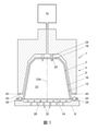
図1は、カプセル内に圧力下で供給される流体を用いて、カプセルから飲用可能な飲料を調製するためのシステム1の1実施態様の概略の断面図である。システム1は、カプセル2と、飲料調製装置4とを備える。該装置4は、カプセル2を保持するための囲み部材6を備える。該装置4はさらに、カプセル2を支持するための閉じ部材(例えば抽出プレート)8を備える。
FIG. 1 is a schematic cross-sectional view of one embodiment of
図1において、明瞭のためにカプセル2と囲み部材6と抽出プレート8との間に隙間が描かれている。使用中、カプセル2は、囲み部材6および抽出プレート部材8と接触していることが理解されよう。囲み部材6は一般に、カプセル2の形状に相補的な形状を有している。飲料調製装置4はさらに、6~20バール、好ましくは12~18バールの範囲の圧力下で、ある量の流体(例えば水)を交換可能なカプセル2へ供給する流体注入手段10を備えている。
In FIG. 1, a gap is drawn between the
図1に示された実施例において、交換可能なカプセル2は、カプセル本体中心軸12Aおよびアルミニウム蓋14を有しているアルミニウムカプセル本体12を備える。本文脈において、「アルミニウム」の意味は、アルミニウム合金をも含むと理解される。本実施例において、アルミニウムカプセル本体12は、側壁16と、第1端部で該側壁16を閉じる底18と、底18に対向する第2端部で周囲壁16の外側に延在し外向きに延在するフランジ20とを備えている。側壁16、底18および蓋14は、物質を抽出及び/又は溶解することによって、飲用可能な飲料の調製のための物質を含む内部空間22を囲む。好ましくは、該物質は、飲用可能な飲料を調製するための抽出可能な製品であり、該抽出可能な製品は、好ましくは、一杯の飲料の調製のために、5~20グラム、好ましくは5~10グラム、より好ましくは5~7グラムの焙煎し挽かれたコーヒーである。カプセルは、当初は封止され、即ち使用前は気密に閉じられている。
In the embodiment shown in FIG. 1, the
図1のシステム1は、入口開口部25を介して抽出可能な製品に流体を供給するための少なくとも1つの入口開口部25を底18に形成するために、カプセル2の底18を刺通するための底刺通手段24を含む。
図1のシステム1はさらに、カプセル2の蓋14を穿孔するために、ここでは閉じ部材8の突出部として具体化された蓋刺通手段26を備える。蓋刺通手段26は、蓋14を破るように配置されうる。内部空間22の内部の(流体)圧力は、閾値圧を超えると、蓋刺通手段26に対して蓋14を十分な力で押圧する。アルミニウム蓋14はこのようにして、カプセル内の流体圧の影響下で飲料調製装置の閉じ部材8上で裂開されるように配置される。
The
カプセル2はさらに、該外向きに延在しているフランジと一体の封止部材28を備えており、図1、3A、および3Bにおいては抽象的なボックスとして表示されているが、図4に関してはより詳細に記載されている。そこでは、カプセル2が囲み部材6内に置かれ、かつ囲み部材6が抽出プレート8によって閉じられる場合に、封止部材28は、囲み部材6との流体封止接触を与えるように配置されている。その結果、カプセル2の外向きに延在するフランジ20と封止部材28の少なくとも1部分とは、囲み部材6と抽出プレート8との間で封止的に係合される。これは、封止部材と自由接触端部との間の流体封止接触が確立されていることを意味する。
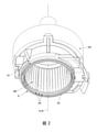
図2に示されたように、飲料調製装置の囲み部材6は、環状要素中心軸41Aと自由端部30とを有する環状要素41を含む。環状要素41の自由端部30には、半径方向に延在している複数の開放溝40が設けられている。該複数の開放溝40は、環状要素41の自由端部30の接線方向に互いに均一に間隔を空けられている。各溝40の接線方向の最長幅は、0.9~1.1mm(ミリメートル)であり、好ましくは、0.95~1.05mm、より好ましくは0.98~1.02mmであり、囲み部材6の軸方向における各溝40の最大高さは、0.01~0.09mm、好ましくは0.03~0.07mm、より好ましくは0.045~0.055mm、そして最も好ましいのは0.05mmである。溝40の数は、90~110の範囲内にあり、好ましくは96である。通常、溝の位置における自由端部の半径方向の幅は、0.05~0.9mm、より具体的には0.2~0.7mm、より具体的には0.3~0.55mmである。
As shown in FIG. 2, the enclosing
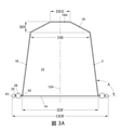
本発明に従うカプセルの実施態様が、図3A及び3Bにより詳細に示されている。図示された実施態様において、外向きに延在しているフランジ20の外径ODFは、カプセル2の底18の直径DBよりも大きい。図示された実施態様において、外向きに延在しているフランジ20の外径ODFは約37.1mmであり、底18の直径DBは約23.3mmである。アルミニウムカプセル本体12の厚さは、該カプセルが該飲料調製装置の該囲み部材内に置かれかつ該囲み部材が該飲料調製装置の閉じ部材によって閉じられる場合に、それが容易に変形されるようになっており、好ましくは、該アルミニウムカプセル本体の該厚さは、100マイクロメートルであるが、他の実施態様において、該厚さは、20~200マイクロメートルでありうる。
Embodiments of capsules according to the present invention are shown in detail with reference to FIGS. 3A and 3B. In the illustrated embodiment, the outer diameter ODF of the
図示された実施態様において、アルミニウム蓋14の壁厚は39μmである。アルミニウム蓋14の壁厚は、好ましくはアルミニウムカプセル本体12の厚さよりも薄い。
In the illustrated embodiment, the wall thickness of the
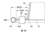
アルミニウムカプセル本体12の側壁16は、底18に対向する自由端部42を有する。アルミニウムカプセル本体12の側壁16の自由端部42の内径IDFは、約29.5mmである。外向きに延在するフランジ20は、その自由端部42から、カプセル本体中心軸12Aを少なくとも実質的に横切る方向に延在している。外向きに延在するフランジ20は、カプセルと囲み部材との間の封止を得るのに有益な湾曲外縁部43を備える。図示された実施態様において、外向きに延在しているフランジ20の湾曲外縁部43は、約1.2mmの最大寸法を有する。アルミニウムカプセル本体12の側壁16の自由端部42と湾曲外縁部43の内縁43Aとの間の距離DIFは、約2.7mmであり、一方、アルミニウムカプセル本体12の側壁16の自由端部42と外向きに延在しているフランジ20の最外縁部43Bとの間の距離DOFは、約3.8mmである。湾曲外縁部43の内縁43Aのカプセル本体中心軸周りの半径は、好ましくは少なくとも32mmである。
The
図3A及び3Bに示されたように、封止部材28は、アルミニウムカプセル本体12の側壁16の自由端部と外向きに延在しているフランジの湾曲外縁部42の内縁43Aとの間に配置されている。封止部材28は、一般的なボックスとして示されているが、以下でより詳細に説明される。封止部材28の実施態様とは関係なく、囲み部材が閉じられたときに最初に囲み部材の自由端部によって接触される封止部材の部分の高さは、正確な封止を与えるためには、少なくとも約0.1mm、より好ましくは少なくとも0.2mm、最も好ましくは少なくとも0.8mm、そして高くても3mm、より好ましくは高くても2mm、そして最も好ましくは高くても1.2mmである。
As shown in FIGS. 3A and 3B, the sealing
図3Aから分かるように、アルミニウムカプセル本体12は切頭されている。図示された実施態様において、アルミニウムカプセル本体12の側壁16は、カプセル本体中心軸12Aに対して直角の線と約97.5°の角度Aを有する。アルミニウムカプセル本体12の底18は、約23.3mmの最大内径DBを有する。アルミニウムカプセル本体12の底18もまた切頭されており、図示された実施態様において、約4.0mmの底の高さBHを有する。底18はさらに、蓋14に対向するほぼ平らな中央部分18Aを有し、中央部分18Aは約8.3mmの直径DEEを有し、中央部分18Aに1つまたは複数の入口開口部25が形成されうる。入口開口部はまた、中央部分18Aと側壁16との間の切頭部分において形成されてもよい。カプセルのアルミニウムカプセル本体12の全高THは、約28.4mmである。
As can be seen from FIG. 3A, the aluminum capsule body 12 is truncated. In the illustrated embodiment, the
図1に示されたシステム1は、1杯の飲用可能な飲料(本実施例においてはコーヒーであり、ここで、物質は焙煎され挽かれたコーヒーである)を調製するために、以下のように操作されうる。
カプセル2は、囲み部材6内に置かれる。抽出プレート8は、カプセル2と接触される。底刺通手段24は、入口開口部25を創るためにカプセル2の底18を刺し通す。流体(ここでは加圧下の熱湯)は、入口開口部25を介して内部空間22内の抽出可能な製品に供給される。熱湯は、挽かれたコーヒーを濡らし、所望の物質を抽出してコーヒー飲料を作る。
The
加圧下で熱湯を内部空間22へ供給する間、カプセル2内の圧力は上昇する。圧力の上昇は、蓋14が変形すること及び抽出プレートの蓋刺通手段26に対して押し付けられることを生じさせる。一度、圧力が或るレベルに達すると、蓋14の裂開強度が超えられて、蓋14は蓋刺通手段26により破れ、出口開口部を作り出す。調製されたコーヒーは、抽出プレート8の出口開口部及び出口32(図1参照)を通ってカプセル2から排出され、容器、例えばカップ(図示せず)に供給されうる。
While the hot water is supplied to the
システム1は、調製の前または開始時に、囲み部材6の自由端部30がカプセル2の封止部材28に力F1を加えて、カプセル2の外向きに延在するフランジ20と飲料調製装置の囲み部材6との間に、流体封止接触を提供する。ここで、カプセルの外側での飲料調製装置の囲み部材内での流体圧P1が0.1~4バール、好ましくは0.1~1バールの範囲内にあるときに、F1は30~150N、好ましくは40~150N、より好ましくは50~100Nである。調製中、囲み部材6の自由端部30は、カプセル2の封止部材28に力F2を及ぼして、カプセル2の外向きに延在しているフランジ20と囲み部材6との間の流体封止接触を提供する。ここで、カプセル2の外側での飲料調製装置の囲み部材6内での流体圧P2が6~20バール、好ましくは12~18バールの範囲内にあるときに、力F2は500~1500Nの範囲内、好ましくは750~1250Nの範囲内にある。図示された実施態様において、外向きに延在するフランジ20と囲み部材6の自由端部30との間に最大の力F2を加えるように、囲み部材6内の流体の、抽出プレート8の方への圧力の影響下で、囲み部材6の自由接触端部は、抽出プレート8に相対的に移動することができる。この移動は、使用中、すなわち特に調製の開始時および調製中に、起きることができる。囲み部材6は、第1部分6Aと第2部分6Bとを有し、第2部分は自由接触端部30を含む。第2部分6Bは、第1位置と第2位置との間で、第1部分6Aに相対的に動きうる。第2部分6Bは、囲み部材6内の流体圧の影響下で閉じ部材8の方向に第1位置から第2位置に向かって移動することができる。上述された力F1は、第2部分6Bが流体圧P1で第1位置にある場合に、達成されうる。上述された力F2は、第2部分6Bが囲み部材6内の流体圧P2の影響下で第2位置の方へ移動される場合に、達成されうる。
Before or at the start of preparation, the
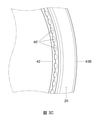
加えられた力の結果として、本発明に従うカプセルの封止部材28は、塑性変形を受け、自由接触端部30の溝40の形に密接に適合し、ひいては調製の開始時の間には、相対的に低い流体圧で囲み部材6とカプセル3との間の流体封止接触を提供するが、調製中は、カプセルの外側での囲み部材内における遥かに高い流体圧で流体封止接触をも提供する。囲み部材の溝40との形の緊密な一致は、使用後の本発明のカプセル2を示す図3Cに示されており、該図は外向きに延在するフランジ20が囲み部材の溝40に一致する変形部40'を含むことを明確に示す。
As a result of the applied force, the encapsulating
これ以降、本発明に従うカプセル2の、外向きに延在しているフランジ20における封止部材28の例示的な実施態様が、図4に関してより詳細に説明されるであろう。
Hereinafter, exemplary embodiments of the sealing
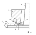
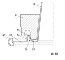
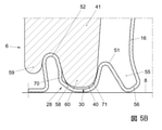
図4Aは、本発明に従うカプセル2の、外向きに延在しているフランジ20に追加的な支持部を形成する封止部材28の第1の実施態様を示す。該封止部材および該カプセル本体の残りの部分は、同じプレート材料から作製されている。封止部材28は、間隔を空けられた2つの突出部50及び51を含み、それぞれが、外向きに延在しているフランジ20のベース部分から、蓋14から離れる方向に軸方向に突出しており、ベース部分に蓋14が取り付けられている。2つの突出部50及び51の間に、プラトー部52が存在する。2つの突出部50及び51の間の間隔は、該カプセルが該飲料調製装置の該囲み部材内に配置され、かつ該囲み部材が該飲料調製装置の閉じ部材によって閉じられる場合に、環状要素6の該自由接触端部が2つの突出部50および51の収束表面の間で圧搾されるようなものである。図4Aに示す実施態様において、プラトー部は、封止部材28と湾曲縁部43との間で、外向きに延在しているフランジ20の部分の上方に距離を置いて配置され、実質的に平坦である。2つの突出部50及び51の間の間隔は、さらに云えば、カプセルが飲料調製物の囲み部材内に置かれかつ囲み部材が飲料調製装置の閉じ部材によって閉じられる場合に、環状要素の自由接触端部が2つの突出部50及び51によって接触されるようなものである。さらに、間隔を空けられた2つの突出部50及び51並びにプラトー部52は、カプセルが飲料調製装置の囲み部材内に置かれかつ該囲み部材が飲料調製装置の閉じ部材によって閉じられる場合に、環状要素の自由接触端部が該プラトー部によって接触されるように配設される。図4Aに見られるように、各突出部50及び51は、アルミニウムカプセル本体の外向きに延在するフランジ20に対して傾けられた突出側壁を備えている。該突出部側壁は、該カプセルが該飲料調製装置の該囲み部材内に置かれかつ該囲み部材が該飲料調製装置の閉じ部材によって閉じられる場合に、それが容易に変形されるように構成されている。
FIG. 4A shows a first embodiment of a sealing
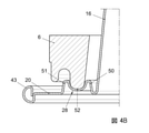
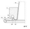
図4Bは、本発明に従うカプセルの、外向きに延在しているフランジ20での封止部材28の第2の実施態様を示す。図4Aと比較して以下の相違点が示される。各突出部50及び51は、アルミニウムカプセル本体の外向きに延在しているフランジ20に対して横方向の突出側壁を含む。さらにこの第2の実施態様において、プラトー部52は湾曲しており、好ましくは環状要素6の自由端部の形状に適合している。
FIG. 4B shows a second embodiment of a sealing
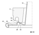
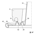
図4Cは、本発明に従うカプセルの、外向きに延在しているフランジ20での封止部材28の第3の実施態様を示しており、封止部材28は、該アルミニウムカプセル本体の側壁16と一緒に該囲み部材のための追加的な支持部を形成する。図示された封止部材28は、外向きに延在しているフランジ20から突出する突出部53と、突出部53の丸みを帯びた最上の端部部分と該アルミニウムカプセル本体の側壁16との間の傾斜した実質的に平坦なプラトー部52とを備える。本実施態様において、支持部は、突出部53、プラトー部52、およびアルミニウムカプセル本体の側壁16によって形成される。突出部53の頂部と側壁16との間の距離は、カプセルが飲料調製装置の囲み部材内に置かれかつ囲み部材が飲料調製装置の閉じ部材によって閉じられる場合に、環状要素6の自由接触端部が突出部53とアルミニウムカプセル本体の側壁16とによって包囲されるようなものである。特に、突出部53とアルミニウムカプセル本体の側壁16との距離は、カプセルが飲料調製装置の囲み部材内に置かれ、かつ囲み部材が飲料調製装置の閉じ部材によって閉じられる場合に、環状要素6の自由接触端部が突出部53および側壁16によって、および図示された実施態様においてはアルミニウムカプセル本体のプラトー部52によっても接触されるようなものである。
FIG. 4C shows a third embodiment of a sealing
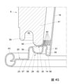
図4Dは、本発明に従うカプセルの、外向きに延在しているフランジ20における封止部材28の第4の実施態様を示す。該封止部材28は、アルミニウムカプセル本体の側壁16と共に、囲み部材のための追加的な支持部を形成する。図4Cと比較すると以下の違いが認められる。この第4の実施態様において、プラトー部52は湾曲され、そして湾曲部分および平坦部分をも含み、該平坦部分は、突出部53と湾曲縁部43との間の外向きに延在しているフランジ20の部分と同じ高さに位置付けられている。湾曲部分は好ましくは、環状要素6の自由接触端部の形状に適合している。図4Eは、本発明に従うカプセルの、外向きに延在するフランジ20での封止部材28の第5の実施態様を示しており、該封止部材28は、アルミニウムカプセル本体の側壁16と共に囲み部材のための支持部を形成する。図4Dと比較すると、以下の違いが認められる。この第5の実施態様において、プラトー部52の平坦部分は、突出部53と湾曲縁部43との間の外向きに延在しているフランジ20の部分の上方に或る距離で置かれている。突出部53との間の距離は、好ましくは0.9~1.25mmであり、それは、幅広く使用されている市販の飲料調製装置(例えばCitiz、Lattisima、U、Maestria、Pixie、Inissia、およびEssenzなど)の該閉じ部材の該自由端部が、突出部53に対して、側壁16がそれに近接した状態で確実に圧搾されることを可能にする。
FIG. 4D shows a fourth embodiment of a sealing
図4C~4Eに示された実施態様において、突出部53は、突出部53と湾曲縁部43との間の外向きに延在しているフランジの部分を横切る外側突出側壁54を含むが、他の実施態様においては、この外側突出側壁54は、外向きに延在しているフランジ20の上記部分に対して傾斜されうる。
In the embodiments shown in FIGS. 4C-4E, the
図4A~4Eに示された全ての実施態様において、該突出部のそれぞれは、突出部頂部を含み、突出部頂部は、該突出部の1部分、例えば、該突出部の半分、3分の1、または4分の1を構成し、それは、蓋14が取り付けられているフランジ28のベース部分から軸方向に最も遠位にある。少なくとも1つの突出部、好ましくは追加的な支持部を形成する全ての突出部は、カプセルが飲料調製装置の囲み部材内に置かれ、かつ囲み部材が飲料調製装置の閉じ部材によって閉じられる場合に、その突出部頂部が環状要素6の自由接触端部に半径方向の力を加えるように構成されている。
In all embodiments shown in FIGS. 4A-4E, each of the protrusions comprises a protrusion apex, which is one portion of the protrusion, eg, half or a third of the protrusion. It constitutes one or a quarter, which is the most distal axially from the base portion of the
図4Fは、本発明に従うカプセルの外向きに延在しているフランジ20での封止部材28の第6の実施態様を示している。例えば図4Bと比較すると、以下の違いが認められる。この第6の実施態様において、プラトー部52は、V字形状になっており、V字形状の底は、外側突出部51と湾曲縁部43との間の外向きに延在しているフランジ20のベース部分と同じレベルにある。このように、該カプセルが該飲料調製装置の該囲み部材内に置かれかつ該囲み部材が該飲料調製装置の閉じ部材によって閉じられる場合に、環状部材6の該自由接触端部のための支持部は形成されていないが、内側突出部50の該突出部頂部が、環状要素6の該自由接触端部に直接外向きに半径方向の力を加え、外側突出部51の該突出部頂部が、環状要素6の該自由接触端部に直接内向きに半径方向の力を加える。このように、該自由接触端部は、封止部材28によって圧搾され、それによって満足のいく封止を提供する。
FIG. 4F shows a sixth embodiment of the sealing
例として図4A、図4B、および図4Fに示されている、封止構造28が突出部50、51とそれらの間にあるプラトー部またはトラフ52とを有するカプセルにおいて、プラトー部またはトラフ52の中心は、カプセルの中心軸の周りに円周方向に延在しており、好ましくは29~33mm、より好ましくは30.0~31.4mm、最も好ましくは30.3~31.0mmの直径を有しており、(半径方向の断面で見たときに、)幅広く使用されている市販の飲料調製装置(例えば、Citiz、Lattisima、U、Maestria、Pixie、Inissia、およびEssenzaなど)の閉じ部材の自由端部が、突出部50と51との間で正確に中心を合わせて着地するようになっており、圧搾効果が、内側および外側突出部50、51にわたって均一に分配されるようになっている。そのような装置における効果的な圧搾に関して、突出部50、51の間の距離は、好ましくは0.9~1.25mmである。
As shown in FIGS. 4A, 4B, and 4F, in a capsule in which the sealing
図4Gは、本発明に従うカプセルの外向きに延在しているフランジ20での封止部材28の第7の実施態様を示している。また、図2に示されているように、該飲料調製装置の囲み部材6は、半径方向に延在している複数の開放溝40を備えた自由接触端部30を有する環状要素41を有しており、半径方向に延在している複数の開放溝40のいくつかが図4Gに示されている。
FIG. 4G shows a seventh embodiment of a sealing
図4A、図4B、および図4Fに示されている例と同様に、封止部材28は、間隔を空けられた2つの突出部50および51を有しており、それぞれが、外向きに延在しているフランジ20のベース部分23から、蓋14から離れる方向に軸方向に突出しており、ベース部分21、23に蓋14が取り付けられている。図4Fに示されている例と同様に、丸みを帯びた底を有するプラトー部52が、2つの突出部50および51の間に置かれている。
Similar to the examples shown in FIGS. 4A, 4B, and 4F, the sealing
図4A、図4B、および図4Fに示されている例と比較した相違点は、図4Gに示されている例では、2つの突出部のうちの第1の突出部51が、外向きに延在しているフランジ20のベース部分23から、2つの突出部のうちの第2の突出部50よりも遠くに突出しているということである。
The difference compared to the example shown in FIGS. 4A, 4B, and 4F is that in the example shown in FIG. 4G, the
別の相違点は、内側突出部51と側壁16との間の環状のトラフ55の底56が、蓋が取り付けられているベース部分23から軸方向に間隔を空けて配設されているということである。好ましくは、底56から該蓋への軸方向の該距離は、プラトー部52から該蓋への軸方向の該距離よりも小さい。
Another difference is that the bottom 56 of the
囲み部材6および/または閉じ部材8が、該カプセルの封止部材28がその間にある状態で互いに向けて移動させられるときに、環状要素41の自由接触端部30は、2つの突出部のうちの第1の突出部51に最初に接触し、その後に、該2つの突出部のうちの第2の突出部に接触しうる(図5A)。
When the enclosing
環状要素41の自由接触端部30が2つの突出部のうちの内側突出部51に接触する場合に、該カプセルは囲み部材6に対して中心を合わせられる。そのうえ、例えば、該カプセルの非円形性もしくは中心のずれた位置決めに局所的に起因して、または、比較的小さい直径を有する該自由接触領域に概して起因して、2つの突出部のうちの内側突出部51が、外側突出部に対して半径方向に遠過ぎる場合には、該自由接触端部は、2つの突出部のうちの内側突出部51を半径方向内向きに付勢する。それによって、該2つの突出部のうちの該外側突出部は、内向きに同伴され、確実な安定した封止圧力が、より小さいその高さに起因するその外側突出部51の比較的小さい変形可能性にもかかわらず、2つの突出部のうちの外側突出部50の上に加えられるようになっている。2つの突出部のうちの外側突出部50の比較的大きい剛性は、それが変形されるときに大きい接触力が加えられることを可能にし(図5B)、比較的高い対抗圧力が、高い圧力抵抗を伴う特に確実な封止を提供する。また、2つの突出部のうちの外側突出部50が、次いで外向きに付勢され、その負荷は、2つの突出部のうちの外側突出部の中のフープ応力によって対抗され、それは、円周方向に均一に分配され、均一に分配された封止圧力が達成されるようになっている。
When the
また、図5aから理解されうるように、環状要素41の自由接触端部30は、内側突出部51に接触する内側円周方向表面部分71と、外側突出部50に接触する外側円周方向表面部分70とを有している。半径方向に延在する開放溝40は、外側表面部分70の中よりも内側表面部分71の中で、より深くなっており、または、溝部は、外側表面部分70の中になくてもよい。したがって、それが小さいほど、比較的硬い外側突出部50は、自由接触端部30の比較的滑らかな外側表面部分70に安定して正確に押し付けられる。
Further, as can be understood from FIG. 5a, the free
2つの突出部50および51の間の距離は、最終的に(図5Aおよび図5B)、該囲み部材が該閉じ部材によって完全に閉じられる場合に、環状要素41の自由接触端部30が、2つの突出部50および51の収束表面の間で圧搾されるようになっている。
The distance between the two
プラトー部52は、蓋14から軸方向に間隔を空けて配設されている。図5Bによって図示されているように、これは、囲み部材6が閉じられるときに、突出部50、51の間のプラトー部52が環状要素41の自由端部30の相対的移動の方向に変位されることを可能にし、囲み部材6が閉じられるときに、突出部50、51が環状要素41の自由端部30に対して内向きに傾けられてロールオフするように促す。これは、(軸方向の閉止圧力に加えて)及ぼされる半径方向の封止圧力を増加させ、増加された封止圧力は、満足のいく封止を提供するために利用可能であるようになっている。
The
より具体的には、図4G、図5A、図5B、および図6に従うリムの該封止部材が囲み部材6の環状要素41と閉じ部材8との間にクランプされる場合に、3つの段階が区別されうる。
More specifically, three steps when the sealing member of the rim according to FIGS. 4G, 5A, 5B, and 6 is clamped between the
第1の段階において、必要な場合には、上記に説明されているような内側突出部51の案内の下で、環状要素41と封止部材28との間の接触が確立され、初期封止が、外側突出部50の略内向きに向く表面部分と、環状要素41の自由端部30の外側表面部分70との間に生成される。外側突出部50のこの内向きに向く表面部分の半径方向の場所、および、外側突出部50の局所的な曲率半径は、互いに接触する面がほとんど垂直方向に配向されることを保証するように配設されている。これは、非常に強力なくさび効果が達成されることを可能にし、非常に小さい垂直方向の閉止力が非常に大きい水平方向の接触圧力を生じさせるようになっている。表面接触によって発生させられる反力は、外側突出部50の中のフープ応力によって主に含まれるので、これらの大きい水平方向の力は、外側突出部50のわずかな変形を伴って加えられる。また、そのようなフープ応力は、封止部材28の残りの部分から主として独立しており、大きい封止力を加えるための高い剛性が、該カプセルの公差および設置間違いに適合するフレキシビリティーと組み合わせられうるようになっている。
In the first step, if necessary, the contact between the
該環状のトラフの底56、および、したがって、該内側突出部の内側フットが、蓋から離れているので、横方向の摩擦および剛性が低減され、封止部材28は、高い程度のフレキシビリティーを有し、該封止面の過度の歪みなしに、ミスアライメントおよび公差の影響に適合する。また、これは、ミスアライメントおよび公差が封止部材28の該接触面の横変位によって適合される場合でも、該接触面のほとんど垂直方向の配向を維持することに貢献する。
Since the bottom 56 of the annular trough, and thus the inner foot of the medial protrusion, is separated from the lid, lateral friction and stiffness are reduced and the sealing
第2の段階において、該封止リングの上への該調製チャンバーの閉止およびさらなる圧縮は、液圧の構築によって支持されている。圧縮力が高まるとき、環状のトラフ55の底56は、機械的なおよび液圧的な荷重によって下向きに押され、該封止部材の全体が、環状のトラフ55の底56が該蓋にタッチするまで、外側突出部50の外側下側端部57の周りで枢動する(図5B)。この枢動移動は、封止部材28の「リジッド本体」タイプの運動、および、該封止部材形状の変形の両方を生じさせ、両方の要因は、加えて追加的な接触圧力が主要な封止面に伝達されることを生じさせる。該変形の多くが塑性的に起こるので、該接触領域は、封止領域に効果的に一致し、いくらかのミスアライメントおよび製造公差が適合されることを可能にする。
In the second step, the closure and further compression of the preparation chamber onto the sealing ring is supported by the construction of hydraulic pressure. When the compressive force is increased, the bottom 56 of the
第3の段階において、軸方向の(ここでは垂直方向の)力のさらなる増加は、封止部材28のさらなる変形を引き起こす(図5B)。本実施態様において、高い接触圧力での高い圧力降下において確実に非常に密閉した封止が、外側突出部50からプラトー部への移行部を形成する傾斜したセクション58の変形によって得られ、そのセクション58は、プラトー部52のより湾曲したセクションと外側突出部50との間に、比較的真っ直ぐなセクションを構成している。そのような変形は、封止部材28と環状要素41の自由端部30の外側表面部分70との間の幅の狭いラインに沿って、特に高い接触圧力を生じさせる。
In the third stage, a further increase in axial (here vertical) force causes further deformation of the sealing member 28 (FIG. 5B). In this embodiment, a reliably very sealed seal at high pressure drops at high contact pressures is obtained by deformation of the
効果的な封止を得るために、外側突出部50が、環状要素41の外側隆起部59と内側隆起部60との間に挟まれ、それによって変形されるということがさらに有利である。
It is further advantageous that the
図5Bに示されているものと同様に、封止部材8が変形されるときに、内側突出部51は曲げて開けられ、環状部材55の底56に向けての封止部材材料の引き離し、および、関連の接触圧力解放が対抗されるようになっている。
Similar to that shown in FIG. 5B, when the sealing
特に、環状要素41および封止部材28の最終的な相互変位に関連して、特定の問題は、ほとんどの環状要素が、環状要素41の外側隆起部59と内側隆起部60との間に1つまたは複数のブリッジ61(図6)を有するということである。そのようなブリッジ61は、環状のヘッドスペース62の中断を構成し、第3の段階の間に、外側突出部50は環状のヘッドスペース62の中へくさび状に打ち込まれる。円周方向にブリッジが始まって終了する、特に移行部における漏れが減少させられる。その理由は、外側突出部は半径方向外向きにロールおよびバックル(buckle)するように形状決めされているからであり、過剰な封止部材材料が外側突出部50と環状要素41との間の封止から離れるように局所的に変位され、それによって、この封止との干渉を低減させ、ブリッジ61の下を通るラインに沿って実質的に連続的な封止を可能にするようになっている。
In particular, in relation to the final mutual displacement of the
これまでの記載において、本発明は、本発明の実施態様の特定の実施例を参照して説明されてきた。しかし、添付の特許請求の範囲に記載された本発明のより広い精神および範囲から逸脱することなく、様々な修正および変更を行うことができることは明らかであろう。
In the description so far, the present invention has been described with reference to specific embodiments of embodiments of the present invention. However, it will be clear that various modifications and modifications can be made without departing from the broader spirit and scope of the invention described in the appended claims.
Claims (81)
該カプセルを受け取るための囲み部材を備える飲料調製装置であって、該囲み部材は、加圧下の流体を該カプセル内に供給するための流体注入手段を備え、該飲料調製装置はさらに、該飲料調製装置の該囲み部材を閉じるための閉じ部材、例えば抽出プレートを備え、該飲料調製装置の該囲み部材はさらに、環状要素中心軸および自由接触端部を有する環状要素を備え、該環状要素の前記自由接触端部は半径方向に延在している複数の開放溝を任意的に備えていてもよい、上記飲料調製装置と、
請求項1~58の何れか1項に記載のカプセルと
を備える、システム。 A system for preparing a drinkable beverage from a capsule using a fluid supplied under pressure into the capsule.
A beverage preparation device comprising an enclosing member for receiving the capsule, wherein the enclosing member comprises a fluid infusion means for supplying a fluid under pressure into the capsule, and the beverage preparing device further comprises the beverage. The enclosing member of the beverage preparation device comprises a closing member for closing the enclosing member of the preparatory device, eg, an extraction plate, which further comprises an annular element having an annular element central axis and a free contact end portion of the annular element. The beverage preparation device and the beverage preparation device, wherein the free contact end may optionally include a plurality of open grooves extending in the radial direction.
A system comprising the capsule according to any one of claims 1 to 58.
上記使用方法。 The method for using a capsule according to any one of claims 1 to 58 in a beverage preparation device including a beverage preparation device for receiving the capsule, wherein the enclosing member supplies a fluid under pressure into the capsule. The beverage preparation device is further provided with a closing member for closing the enclosure member of the beverage preparation device, for example, an extraction plate, and the beverage preparation device is further provided with an annular element. The free contact end of the annular element comprises an annular element having a central axis and a free contact end, optionally comprising a plurality of radial grooves, the capsule being the fluid of the beverage preparation device. It contains the substance for preparing a drinkable beverage by extracting and / or dissolving the substance with a fluid supplied into the capsule under pressure by an infusion means, the capsule being made of aluminum having a capsule body central axis. The aluminum capsule body comprises a bottom, a sidewall, and an outwardly extending flange, the capsule further comprising aluminum attached to the outwardly extending flange. Provided with a lid, the lid closed the capsule hermetically, where the capsule is placed within an enclosure of the beverage preparation device and the enclosure is closed by the closure of the beverage preparation device. In order to provide a fluid sealing contact with the enclosing member of the beverage preparation device, the capsule further comprises a sealing member integrated with the outwardly extending flange, and thus the outwardly extending member of the capsule. The extending flange and at least one portion of the sealing member of the capsule are hermetically engaged between the enclosing member and the closing member of the beverage preparation device.
The above usage.
該環状要素の該自由接触端部が該2つの突出部のうちの該内側突出部に接触する時に、該カプセルは、該囲み部材に対して中心を合わせられ、または半径方向内向きに付勢され、該2つの突出部のうちの該外側突出部を同伴する、請求項72~76の何れか1項に記載の使用方法。 The capsule is the capsule according to any one of claims 2 to 22, wherein the enclosing member and / or the closing member is moved toward the other together with the sealing member of the capsule in the middle. When so, the free contact end of the annular element first contacts the first protrusion of the two protrusions, followed by the second of the two protrusions. Can touch the protrusion,
When the free contact end of the annular element contacts the medial protrusion of the two protrusions, the capsule is centered or radially inwardly urged with respect to the enclosure. The method of use according to any one of claims 72 to 76, wherein the outer protrusion of the two protrusions is accompanied.
The system is the system of claim 64, wherein the outer protrusion of the two protrusions rolls and buckles radially outwards when it is compressed by the bridge. Item 9. The method of use according to any one of Items 72 to 80.
Applications Claiming Priority (10)
| Application Number | Priority Date | Filing Date | Title |
|---|---|---|---|
| NLPCT/NL2015/050352 | 2015-05-15 | ||
| NLPCT/NL2015/000018 | 2015-05-15 | ||
| NL2015000018 | 2015-05-15 | ||
| NLPCT/NL2015/050349 | 2015-05-15 | ||
| NL2015050349 | 2015-05-15 | ||
| NL2015050352 | 2015-05-15 | ||
| NLPCT/NL2015/050611 | 2015-09-03 | ||
| NL2015050611 | 2015-09-03 | ||
| PCT/NL2016/050350 WO2016186496A1 (en) | 2015-05-15 | 2016-05-13 | A capsule, a system for preparing a potable beverage from such a capsule and use of such a capsule in a beverage preparation device |
| JP2017559326A JP6978943B2 (en) | 2015-05-15 | 2016-05-13 | Capsules, systems for preparing drinkable beverages from such capsules, and how to use such capsules in beverage preparation equipment. |
Related Parent Applications (1)
| Application Number | Title | Priority Date | Filing Date |
|---|---|---|---|
| JP2017559326A Division JP6978943B2 (en) | 2015-05-15 | 2016-05-13 | Capsules, systems for preparing drinkable beverages from such capsules, and how to use such capsules in beverage preparation equipment. |
Publications (2)
| Publication Number | Publication Date |
|---|---|
| JP2022017579A true JP2022017579A (en) | 2022-01-25 |
| JP7487161B2 JP7487161B2 (en) | 2024-05-20 |
Family
ID=57838585
Family Applications (4)
| Application Number | Title | Priority Date | Filing Date |
|---|---|---|---|
| JP2017559326A Active JP6978943B2 (en) | 2015-05-15 | 2016-05-13 | Capsules, systems for preparing drinkable beverages from such capsules, and how to use such capsules in beverage preparation equipment. |
| JP2017559325A Active JP6934425B2 (en) | 2015-05-15 | 2016-05-13 | Capsules, systems for preparing drinkable beverages from such capsules, and how to use such capsules in beverage preparation equipment. |
| JP2021135944A Active JP7361078B2 (en) | 2015-05-15 | 2021-08-23 | Capsules, systems for preparing drinkable beverages from such capsules, and methods of using such capsules in beverage preparation equipment |
| JP2021184609A Active JP7487161B2 (en) | 2015-05-15 | 2021-11-12 | Capsule, system for preparing a drinkable beverage from such a capsule, and method for using such a capsule in a beverage preparation device - Patents.com |
Family Applications Before (3)
| Application Number | Title | Priority Date | Filing Date |
|---|---|---|---|
| JP2017559326A Active JP6978943B2 (en) | 2015-05-15 | 2016-05-13 | Capsules, systems for preparing drinkable beverages from such capsules, and how to use such capsules in beverage preparation equipment. |
| JP2017559325A Active JP6934425B2 (en) | 2015-05-15 | 2016-05-13 | Capsules, systems for preparing drinkable beverages from such capsules, and how to use such capsules in beverage preparation equipment. |
| JP2021135944A Active JP7361078B2 (en) | 2015-05-15 | 2021-08-23 | Capsules, systems for preparing drinkable beverages from such capsules, and methods of using such capsules in beverage preparation equipment |
Country Status (18)
| Country | Link |
|---|---|
| US (3) | US10835074B2 (en) |
| JP (4) | JP6978943B2 (en) |
| KR (4) | KR102618708B1 (en) |
| CN (3) | CN107848702B (en) |
| AU (6) | AU2016264690A1 (en) |
| BE (2) | BE1023500A9 (en) |
| BR (2) | BR112017024485B1 (en) |
| CA (2) | CA2985970A1 (en) |
| DE (1) | DE202016106169U1 (en) |
| DK (4) | DK3119702T3 (en) |
| ES (2) | ES2733545T3 (en) |
| GB (1) | GB2572692B (en) |
| IL (4) | IL255676B (en) |
| IT (2) | ITUA20163462A1 (en) |
| MX (4) | MX2017014637A (en) |
| NL (2) | NL2016785B1 (en) |
| PT (2) | PT3119702T (en) |
| RU (2) | RU2705505C2 (en) |
Families Citing this family (20)
| Publication number | Priority date | Publication date | Assignee | Title |
|---|---|---|---|---|
| EP3521210B1 (en) * | 2010-07-22 | 2020-01-08 | K-fee System GmbH | Portion capsule with barcode |
| EP3134331B1 (en) | 2015-05-15 | 2018-07-11 | Koninklijke Douwe Egberts B.V. | A capsule, a system for preparing a potable beverage from such a capsule and use of such a capsule in a beverage preparation device. |
| PT3119702T (en) * | 2015-05-15 | 2020-03-05 | Douwe Egberts Bv | A capsule, a system for preparing a potable beverage from such a capsule and use of such a capsule in a beverage preparation device |
| RU2710768C2 (en) | 2015-05-15 | 2020-01-13 | Конинклейке Дауве Егбертс Б.В. | Capsule, system for preparing drink suitable for drinking from similar capsule and use of such capsule in beverage preparation device |
| CN107848701B (en) | 2015-05-15 | 2021-02-02 | 皇家戴维艾格伯茨有限公司 | Capsule, system for preparing a potable beverage from such a capsule and method of use of such a capsule in a beverage preparation device |
| WO2016186491A1 (en) | 2015-05-15 | 2016-11-24 | Koninklijke Douwe Egberts B.V | A capsule, a system for preparing a potable beverage from such a capsule and use of such a capsule in a beverage preparation device |
| CA2985975A1 (en) | 2015-05-15 | 2016-11-24 | Koninklijke Douwe Egberts B.V. | A capsule, a system for preparing a potable beverage from such a capsule and use of such a capsule in a beverage preparation device |
| NL2016780B1 (en) | 2016-05-13 | 2017-11-16 | Douwe Egberts Bv | A capsule, a system for preparing a potable beverage from such a capsule and use of such a capsule in a beverage preparation device |
| NL2016779B1 (en) | 2016-05-13 | 2017-11-16 | Douwe Egberts Bv | A capsule and a system for preparing a potable beverage from such a capsule |
| NL2019254B9 (en) | 2016-10-07 | 2018-09-10 | Douwe Egberts Bv | A capsule, a system for preparing a potable beverage from such a capsule and use of such a capsule in a beverage preparation device |
| NL2019253B1 (en) | 2017-07-14 | 2019-01-28 | Douwe Egberts Bv | Assembly of a capsule and a brew chamber, brew chamber, beverage preparation machine, capsule and use of a capsule. |
| WO2019197940A1 (en) * | 2018-04-11 | 2019-10-17 | Goglio S.P.A. | Capsule for preparing beverages, particularly coffee |
| TW202023919A (en) * | 2018-09-14 | 2020-07-01 | 瑞士商雀巢製品股份有限公司 | Capsule for beverage preparation with integrally formed sealing member |
| EP3863945A1 (en) * | 2018-10-10 | 2021-08-18 | Société des Produits Nestlé S.A. | Capsule for beverage preparation with integrally formed sealing member |
| NL2022190B1 (en) * | 2018-12-12 | 2020-07-03 | Douwe Egberts Bv | Air purge groove |
| NL2022267B1 (en) * | 2018-12-20 | 2020-07-15 | Douwe Egberts Bv | System for preparing a beverage from a capsule using a fluid supplied under pressure into the capsule and a capsule for use in such a system |
| EP3741269A1 (en) * | 2019-05-21 | 2020-11-25 | Delica AG | Brewing chamber, brewing unit, machine and system for preparing a liquid food product from a capsule |
| IT201900007962A1 (en) * | 2019-06-04 | 2020-12-04 | Bisio Progetti Spa | CAPSULE FOR THE PREPARATION OF BEVERAGES WITH CONTROLLED OPENING |
| CN112741496B (en) * | 2019-10-31 | 2022-10-18 | 广东美的生活电器制造有限公司 | Brewing device and beverage machine |
| EP4255826A2 (en) * | 2020-12-07 | 2023-10-11 | GCS German Capsule Solution GmbH | Single serve capsule for preparing a beverage in a beverage preparation machine, and method for producing a single serve capsule |
Citations (3)
| Publication number | Priority date | Publication date | Assignee | Title |
|---|---|---|---|---|
| JP2008517838A (en) * | 2004-10-25 | 2008-05-29 | ネステク ソシエテ アノニム | Capsule with sealing means |
| WO2014012783A2 (en) * | 2012-07-16 | 2014-01-23 | Tuttoespresso S.R.L. | Capsule and brewing system with adaptable sealing element |
| WO2014118812A1 (en) * | 2013-01-29 | 2014-08-07 | Bisio Progetti S.P.A. | Capsule for preparing infusion beverages and process for operating said capsule |
Family Cites Families (179)
| Publication number | Priority date | Publication date | Assignee | Title |
|---|---|---|---|---|
| US4651538A (en) | 1985-09-06 | 1987-03-24 | Schneider Metal Manufacturing Co. | Beverage cooler having a cold plate and plastic ice bin |
| GB2242159B (en) | 1990-03-19 | 1994-02-02 | Toyo Kohan Co Ltd | Copolyester resin film-metal sheet laminates |
| EP0468079B1 (en) | 1990-07-27 | 1996-09-18 | Societe Des Produits Nestle S.A. | Closed cartridge for making a beverage, process and device for manufacturing such a cartridge |
| US5897899A (en) | 1991-05-08 | 1999-04-27 | Nestec S.A. | Cartridges containing substances for beverage preparation |
| DE69615001T2 (en) * | 1996-05-10 | 2002-03-21 | Nestle Sa | Closed cartridge with zones of reduced thickness |
| US5798599A (en) | 1996-10-24 | 1998-08-25 | Dukane Corporation | Ultrasonic transducer assembly using crush foils |
| DE69616346T2 (en) | 1996-11-22 | 2002-04-18 | Nestle Sa | Closed container containing a powdery substance |
| GB9702475D0 (en) | 1997-02-07 | 1997-03-26 | Metal Box Plc | Can ends |
| DE59805446D1 (en) | 1998-12-16 | 2002-10-10 | Alcan Tech & Man Ag | Lid for closing containers |
| JP2000262405A (en) | 1999-03-18 | 2000-09-26 | Soc Prod Nestle Sa | Sealed cartridge for drink extraction |
| KR100627571B1 (en) * | 1999-11-05 | 2006-09-22 | 도요 보세키 가부시키가이샤 | Polyester laminate film, metal plate laminated with this film and film-laminated metal container |
| US20110027547A1 (en) | 2000-05-02 | 2011-02-03 | Reactive Nanotechnologies, Inc. | Methods of making reactive composite materials and resulting products |
| TWI236360B (en) | 2000-06-30 | 2005-07-21 | Nestle Sa | Capsule cage |
| PT1190959E (en) | 2000-09-26 | 2004-06-30 | Nestle Sa | CLOSED PACKAGE FOR CONFECTIONING A DRINK INTENDED TO BE EXTRACTED UNDER PRESSURE |
| EP1203554A1 (en) | 2000-11-03 | 2002-05-08 | Societe Des Produits Nestle S.A. | Device for extracting food material stored in a reloading cartridge |
| US6550157B1 (en) | 2001-11-09 | 2003-04-22 | Robert W. Harding | Recessed dryer vent system |
| KR100653584B1 (en) | 2001-11-21 | 2006-12-05 | 교도 인사쯔 가부시키가이샤 | Laminates and packaging containers |
| EP1495702A1 (en) | 2003-07-10 | 2005-01-12 | Nestec S.A. | Device for the extraction of a cartridge |
| US7758936B2 (en) | 2003-09-18 | 2010-07-20 | Boehringer Ingelheim Gmbh | Pharmaceutical blister |
| US7237698B2 (en) | 2004-01-20 | 2007-07-03 | Brian Francis Jackman | Pressure activated self opening container and seal |
| DE602005017929D1 (en) | 2004-10-25 | 2010-01-07 | Nestec Sa | Capsule with elastically resilient sealing element |
| US8403951B2 (en) | 2005-03-08 | 2013-03-26 | Novartis Ag | Phacoemulsification tip |
| DE602006001573D1 (en) | 2006-03-31 | 2008-08-07 | Nestec Sa | Capsule with liquid-sealed outer seal |
| PT2012994E (en) | 2006-04-24 | 2012-09-20 | Nestec Sa | Method for producing a capsule for preparing a beverage with a sealing member for water tightness attached thereto |
| ES2326909T3 (en) * | 2006-04-24 | 2009-10-21 | Nestec S.A. | CAPSULE FOR THE PREPARATION OF A DRINK WITH A HERMETIC CLOSURE ELEMENT UNITED TO THE SAME AND MANUFACTURING PROCEDURE OF THE SAME. |
| PL1859714T3 (en) | 2006-05-24 | 2009-07-31 | Nestec Sa | Brewing device and brewing capsule system with a capsule holder for facilitating insertion and removal of capsules |
| ATE495690T1 (en) | 2006-05-24 | 2011-02-15 | Nestec Sa | CAPSULE PERFORATION MODULE |
| CN101454227B (en) | 2006-05-29 | 2010-11-03 | 雀巢产品技术援助有限公司 | Coffee capsule with a deformable sealing element |
| KR20090029753A (en) | 2006-06-01 | 2009-03-23 | 어드밴스드 플라스틱스 테크놀로지즈 룩셈부르크 에스.에이. | Plastic multi-piece containers and methods and systems of making same |
| EP1882431B1 (en) | 2006-07-24 | 2010-04-28 | Nestec S.A. | Method for delivering a long coffee extract from a capsule in a reduced flow time |
| PT1882432E (en) | 2006-07-24 | 2010-10-18 | Nestec Sa | Method for delivering faster a short coffee extract from capsule |
| DE202006013189U1 (en) | 2006-08-25 | 2006-10-26 | Tchibo Gmbh | Hot beverage e.g. meal coffee, making system, has jacket base with silicon plate having hole which is sealed depending on material properties of plate, before lower mandrel is pulled out from plate |
| ITTO20060661A1 (en) | 2006-09-18 | 2008-03-19 | Nicoletta Francovicchio | SEALED CAPSULA FOR THE PRODUCTION OF A BEVERAGE |
| JP5185276B2 (en) | 2006-09-26 | 2013-04-17 | ネステク ソシエテ アノニム | Extraction system for preparing beverages from cartridges |
| ES2336036T3 (en) | 2007-03-06 | 2010-04-07 | Nestec S.A. | DEVICE FOR THE PREPARATION OF A FOOD LIQUID FROM A CAPSULE. |
| PL2155021T3 (en) * | 2007-06-05 | 2011-09-30 | Nestec Sa | Capsule system, device and method for preparing a food liquid contained in a receptacle by centrifugation |
| PL2205133T3 (en) | 2007-10-04 | 2011-10-31 | Nestec Sa | Beverage brewing unit |
| DE102007060150B4 (en) | 2007-12-13 | 2010-01-21 | Inde Plastik Betriebsgesellschaft Mbh | Closed sachet with sealing ring and packaging for the production thereof |
| AR071333A1 (en) | 2008-01-15 | 2010-06-16 | Nestec Sa | SYSTEM FOR THE EXTRACTION OF DRINKS, KIT AND CARTRIDGE SEAL ADAPTER TO BE USED IN SUCH SYSTEM, AND METHOD FOR INSERTING A CARTRIDGE SEAL ADAPTER IN A DRINK EXTRACTION DEVICE |
| WO2009097961A1 (en) | 2008-02-05 | 2009-08-13 | Alcan Technology & Management Ltd. | Cover and method for the production thereof |
| ATE508074T1 (en) * | 2008-03-12 | 2011-05-15 | Nestec Sa | CAPSULE WITH FLOW REGULATION AND FILTER ELEMENT |
| DE102008014758A1 (en) * | 2008-03-18 | 2009-10-08 | Inde Plastik Betriebsgesellschaft Mbh | Closed portion package for soluble coffee substance for espresso machine, has side wall provided with carrier section, and inner section, which is formed of flexible plastic foil deformable under pressure and laminated on carrier section |
| US9572450B2 (en) | 2008-03-20 | 2017-02-21 | Nestec S.A. | Beverage production device for producing a beverage from a single-use capsule |
| CN102007052B (en) | 2008-04-14 | 2013-06-05 | 艾斯克咖啡有限公司 | Capsule for beverage preparation |
| ES2377030T3 (en) | 2008-07-15 | 2012-03-21 | Nestec S.A. | Procedure for applying a liquid gasket rubber on a capsule |
| EP2165937A1 (en) | 2008-09-23 | 2010-03-24 | Nestec S.A. | Bicoloured aluminium container and process for producing said container |
| FR2938417B1 (en) | 2008-11-17 | 2013-07-12 | Tirouvady Moutty | CAPSULE FOR PERCOLATING AROMATIC PRODUCT SUCH AS COFFEE |
| AU2009335236B2 (en) | 2009-01-05 | 2015-07-23 | Société des Produits Nestlé S.A. | Capsule with flow control and filtering member |
| US8205415B2 (en) | 2009-01-16 | 2012-06-26 | Kraft Foods Global Brands Llc | Method of packaging and shipping roast and ground coffee |
| JP2012515601A (en) * | 2009-01-23 | 2012-07-12 | エシカル コーヒー カンパニー ソシエテ アノニム | Capsules for preparing beverages |
| EP2364930B1 (en) | 2009-03-19 | 2018-12-05 | Nestec S.A. | Capsule for preparing coffee in a device comprising a cartridge holder with relief and recessed elements |
| EP2230195B1 (en) | 2009-03-19 | 2018-04-25 | Nestec S.A. | Capsule with filtering insert for preparing a coffee beverage |
| WO2010116284A2 (en) | 2009-04-08 | 2010-10-14 | Ethical Coffee Company Sa | Brewing device and capsule for preparing a drink |
| IT1393936B1 (en) | 2009-04-09 | 2012-05-17 | I T A Ca S R L Ora Mitaca S R L | CARTRIDGE FOR COFFEE AND SOLUBLE PRODUCTS FOR THE PREPARATION OF DRINKS |
| DK2510843T4 (en) * | 2009-06-17 | 2020-03-09 | Douwe Egberts Bv | SYSTEM, CAPSEL, AND PROCEDURE FOR MANUFACTURING A BEVERAGE |
| CA2765322C (en) | 2009-06-17 | 2018-02-27 | Sara Lee/De B.V. | Capsule, system and method for preparing a beverage |
| DK2443046T3 (en) | 2009-06-17 | 2016-01-04 | Koninkl Douwe Egberts Bv | A capsule for containing beverage ingredients |
| AT508144B1 (en) | 2009-06-30 | 2010-11-15 | Teich Ag | PROCESS FOR PRODUCING PACKAGED PLATINES |
| DE202009009125U1 (en) | 2009-07-02 | 2010-09-09 | Nestec S.A. | Kit for improving the sealing properties of a fillable capsule |
| US9414709B2 (en) * | 2009-07-24 | 2016-08-16 | Ethical Coffee Company Sa | Device for preparing a beverage extracted from a capsule |
| ATE526255T1 (en) | 2009-08-05 | 2011-10-15 | Nestec Sa | CAPSULE WITH RELIEF-SHAPED SEALING ELEMENT |
| PT2284100E (en) | 2009-08-05 | 2011-08-25 | Nestec Sa | Capsule with dedicated sealing means |
| ES2535755T3 (en) * | 2009-08-19 | 2015-05-14 | Nestec S.A. | Capsule for the preparation of a coffee extract provided with a structure that facilitates water injection drilling |
| US20110185911A1 (en) | 2009-10-21 | 2011-08-04 | Gino Rapparini | Filtering permeable thermoformed container for beverage-making products with a flat rim |
| JP2013511308A (en) * | 2009-11-19 | 2013-04-04 | ネステク ソシエテ アノニム | Capsule and method for preparing beverages such as coffee from capsules |
| EP2335529B1 (en) | 2009-12-18 | 2012-08-08 | Delica AG | Device for preparing a drink and capsule |
| AU2011209447B2 (en) | 2010-01-29 | 2015-08-20 | Société des Produits Nestlé S.A. | Capsule and system for preparing a beverage by centrifugation in a beverage production device |
| AU2011229234B2 (en) | 2010-03-19 | 2015-06-25 | Nestec S.A. | A beverage machine using ingredient capsules |
| PL2374383T3 (en) * | 2010-04-07 | 2013-04-30 | Nestec Sa | Extraction system for the production of a beverage using a capsule |
| CN103038144A (en) | 2010-06-18 | 2013-04-10 | 比塞尔康控股有限公司 | Capsule, device and method for preparing a beverage by extraction |
| CN103025216B (en) | 2010-06-28 | 2016-03-30 | 雀巢产品技术援助有限公司 | Capsule sensor-based system |
| DE102010027484A1 (en) | 2010-07-16 | 2012-01-19 | Krüger Gmbh & Co. Kg | Portion capsule i.e. coffee portion capsule, for manufacturing e.g. espresso, has base element comprising edge with fastening plane, membrane attached at plane, and sealing provided on and/or before fastening plane of edge |
| EP4000479A3 (en) * | 2010-07-16 | 2022-06-22 | Société des Produits Nestlé S.A. | Preparing a beverage by centrifugation |
| FR2962893A1 (en) | 2010-07-21 | 2012-01-27 | Capsa Sa | HERMETIC CAPSULE FOR PRESSURIZED EXTRACT DRINK |
| EP2412646A1 (en) | 2010-07-28 | 2012-02-01 | Nestec S.A. | A capsule for food preparation |
| DE102010034260A1 (en) | 2010-08-13 | 2012-02-16 | Valeo Schalter Und Sensoren Gmbh | Sensor holder for fixing sensor, particularly ultrasonic sensors, to cover part of vehicle, has fixing section and retaining section, where retaining section has inlet opening for introducing sensor |
| DE102010047890B4 (en) | 2010-08-16 | 2019-05-29 | K-Fee System Gmbh | Portion capsule with a filter fabric |
| DE102011012881A1 (en) | 2010-09-22 | 2012-03-22 | Krüger Gmbh & Co. Kg | Portion capsule and method of making a beverage with a portion capsule |
| CA2813460C (en) | 2010-10-08 | 2017-08-22 | Louis Deuber | Extraction device and sealing system |
| PT2645907E (en) | 2010-11-30 | 2014-07-10 | Nestec Sa | Capsule for the preparation of a beverage in beverage production device |
| EP2667757B1 (en) | 2011-01-28 | 2016-09-14 | Nestec S.A. | Beverage production system and capsule with force ring |
| MA34895B1 (en) | 2011-02-16 | 2014-02-01 | Nestec Sa | CONTAINER FOR PREPARING BEVERAGE COMPRISING AN IMPROVED PERCEABLE SHEET AND PROCESS FOR PREPARING A BEVERAGE |
| IT1403855B1 (en) | 2011-02-17 | 2013-11-08 | E T I S R L | CAP FOR CONTAINMENT OF A PREPARATION FOR HOT DRINK |
| WO2012144885A1 (en) | 2011-03-03 | 2012-10-26 | Biserkon Holdings Ltd. | Capsule |
| ES2653157T3 (en) | 2011-03-03 | 2018-02-06 | Biserkon Holdings Ltd. | Capsule to prepare a drink by extraction |
| US9833107B2 (en) * | 2011-03-07 | 2017-12-05 | Ethical Coffee Company Sa | Capsule for preparing a beverage, and matching capsule holder |
| GB2488799A (en) | 2011-03-08 | 2012-09-12 | Kraft Foods R & D Inc | Drinks Pod without Piercing of Outer Shell |
| WO2012123857A1 (en) | 2011-03-11 | 2012-09-20 | Ethical Coffee Company Sa | Capsule holder for a capsule for preparing a beverage |
| US20120244384A1 (en) | 2011-03-22 | 2012-09-27 | Ball Corporation | Stress Corrosion Resistant Aluminum Beverage End Closure |
| GB2489409B (en) * | 2011-03-23 | 2013-05-15 | Kraft Foods R & D Inc | A capsule and a system for, and a method of, preparing a beverage |
| JP5888325B2 (en) | 2011-03-31 | 2016-03-22 | 旭硝子株式会社 | Vacuum degassing apparatus, glass product manufacturing apparatus, and glass product manufacturing method |
| FR2973209B1 (en) | 2011-04-01 | 2014-07-04 | Ahbla Ganibardi | CAPSULE OF BEVERAGE PRODUCT |
| WO2013043048A1 (en) | 2011-09-20 | 2013-03-28 | Koninklijke Douwe Egberts B.V. | Beverage filter systems and methods |
| ITBS20110129A1 (en) | 2011-09-26 | 2013-03-27 | Capitani Srl | CAPSULE FOR THE PRODUCTION OF AN INFUSED DRINK |
| CA2850009A1 (en) * | 2011-09-28 | 2013-04-04 | Tuttoespresso S.R.L. | Beverage capsule with sealing element |
| ITMI20111847A1 (en) | 2011-10-10 | 2013-04-11 | Goglio Spa | CARTRIDGE FOR COFFEE AND SOLUBLE PRODUCTS IN GENERAL |
| WO2013060654A1 (en) | 2011-10-24 | 2013-05-02 | Nestec S.A. | Capsule for the preparation of a beverage by centrifugation with a sealing flange |
| TWI568134B (en) | 2011-10-24 | 2017-01-21 | 仁寶電腦工業股份有限公司 | Charging control method |
| ES1075815Y (en) | 2011-10-25 | 2012-03-08 | Inventos Para Sist S Vending S L | MONODOSIS CAPSULE FOR ESPRESSO COFFEE MACHINES |
| WO2013068242A1 (en) | 2011-11-07 | 2013-05-16 | Nestec S.A. | Capsule for preparing a beverage with enhanced sealing means |
| CN103946870B (en) | 2011-11-15 | 2020-06-12 | 雀巢产品有限公司 | Holder and capsule for preparing a beverage by centrifugation, system and method for preparing a beverage by centrifugation |
| WO2013076519A1 (en) * | 2011-11-22 | 2013-05-30 | Tuttoespresso S.R.L. | Capsule for beverage preparation |
| EP2785613B1 (en) | 2011-11-30 | 2016-03-02 | Alain Frydman | Capsule with improved guidance for preparing beverages by extraction |
| US8986763B2 (en) | 2012-02-27 | 2015-03-24 | Rialto Coffee Company Ltd. | Optimal extraction rate coffee capsule with effective seal for diverse group heads |
| US20130224340A1 (en) | 2012-02-27 | 2013-08-29 | Hanan BenDavid | Optimal extraction rate coffee capsule with effective seal for diverse group heads |
| ITBO20120103A1 (en) | 2012-03-05 | 2013-09-06 | Macchiavelli Srl | CAPS FOR INFUSION PRODUCTS |
| EP2822429A1 (en) | 2012-03-09 | 2015-01-14 | Koninklijke Philips N.V. | Appliance which is suitable to be used for making a beverage in at least two different ways |
| ITVR20120043A1 (en) | 2012-03-14 | 2013-09-15 | Coffee Star S A | DRINK PRODUCTION SYSTEM |
| ES2385235B1 (en) | 2012-03-15 | 2013-05-30 | Javier Lastra Ruiz | Instant Hot Drink Capsule |
| ITBO20120141A1 (en) | 2012-03-16 | 2013-09-17 | Aroma System Srl | CAPSULE TO GET DRINKS EXPRESS TYPE AND METHOD OF OBTAINING ESPRESSO DRINKS |
| WO2013144838A1 (en) | 2012-03-26 | 2013-10-03 | Sarong Societa' Per Azioni | Capsule for beverage and method for manufacturing said capsule |
| FR2989258B1 (en) | 2012-04-12 | 2014-07-11 | Tirouvady Moutty | REINFORCED CAPSULE FOR PERCOLATING A PRODUCT SUCH AS COFFEE |
| WO2013157924A1 (en) | 2012-04-17 | 2013-10-24 | Biserkon Holdings Ltd. | Capsule and device for preparing beverages and method for manufacturing a capsule |
| WO2013157927A1 (en) | 2012-04-20 | 2013-10-24 | Telefonaktiebolaget L M Ericsson (Publ) | Method, device, network entity and computer program product for providing an ip service application |
| WO2013164669A1 (en) | 2012-05-02 | 2013-11-07 | Russon Holdings Limited | Capsule for use in coffee extraction machines |
| AU2015255218B2 (en) | 2012-06-18 | 2017-05-25 | K-Fee System Gmbh | Portion capsule and method for producing a beverage by means of a portion capsule |
| DE102012105282A1 (en) | 2012-06-18 | 2013-12-19 | K-Fee System Gmbh | Portion capsule and method of making a beverage with a portion capsule |
| WO2013190426A1 (en) | 2012-06-19 | 2013-12-27 | Rialto Coffee Company Ltd. | Optimal extraction rate coffee capsule with effective seal for diverse group heads |
| ES1077395Y (en) | 2012-06-26 | 2012-10-15 | Solubles S A Prod | Capsule to prepare infusions |
| GB2503697B (en) | 2012-07-04 | 2014-12-10 | Alex Gort-Barten | Coffee Capsule |
| EP2682028B1 (en) | 2012-07-04 | 2019-03-13 | Piero Kobler | Insert for a portioning coffee machine |
| CN104619609A (en) * | 2012-07-16 | 2015-05-13 | 图托埃布莱束有限公司 | Capsule with improved sealing element |
| LU92050B1 (en) | 2012-07-23 | 2014-01-24 | Brain Corp S A | Capsule for the preparation of a drink such as a coffee capsule. |
| JP2015529508A (en) * | 2012-08-24 | 2015-10-08 | ネステク ソシエテ アノニム | Capsules for use with food preparation machines |
| ES2473740B1 (en) | 2012-09-03 | 2015-06-02 | Quick Expresso Cap System, S.L. | CAPSULE FOR COFFEE MACHINES. |
| CH707035A2 (en) | 2012-09-26 | 2014-03-31 | Alice Allison Sa | Sachet for espresso machines. |
| ES2593460T3 (en) | 2012-10-05 | 2016-12-09 | Nestec S.A. | Drink capsule with splash prevention medium |
| DE112013002899A5 (en) * | 2012-10-29 | 2015-08-06 | Cstec Gmbh | Capsule for holding a brewing product such as coffee, tea and the like, as well as methods for closing such a capsule |
| US20150298897A1 (en) | 2012-11-09 | 2015-10-22 | Bean Technologies Limited | Capsule for use in coffee extraction machines |
| CN104780815B (en) | 2012-11-13 | 2019-06-11 | 雀巢产品技术援助有限公司 | For forming the opening device of big opening in capsule |
| CH707516A2 (en) * | 2013-01-17 | 2014-07-31 | Alice Allison Sa | Capsule part for a coffee capsule coffee capsule. |
| WO2014125390A1 (en) | 2013-02-13 | 2014-08-21 | Ethical Coffee Company Sa | Basket for drinks-preparing machine |
| ES1078818Y (en) | 2013-02-22 | 2013-06-10 | Solubles S A Prod | Capsule to prepare infusions |
| CN105431360A (en) | 2013-04-10 | 2016-03-23 | 图托埃布莱束有限公司 | Capsule and system for preparing beverages |
| GB201308929D0 (en) * | 2013-05-17 | 2013-07-03 | Kraft Foods R & D Inc | A beverage preparation system, a capsule and a method for forming a beverage |
| GB201308927D0 (en) * | 2013-05-17 | 2013-07-03 | Kraft Foods R & D Inc | A beverage preparation system, a capsule and a method for forming a beverage |
| EP4190211A1 (en) | 2013-05-17 | 2023-06-07 | Koninklijke Douwe Egberts B.V. | A beverage preparation system, a capsule and a method for forming a beverage |
| UA117832C2 (en) | 2013-05-29 | 2018-10-10 | К-Фее Зюстем Гмбх | PORTION COVER CONTAINING LIQUID DISTRIBUTOR |
| ITMI20130975A1 (en) * | 2013-06-13 | 2014-12-14 | Goglio Spa | CARTRIDGE FOR SOLUBLE PRODUCTS WITH SEALING ELEMENT |
| DK3010838T4 (en) | 2013-06-17 | 2020-04-27 | Delica Ag | Capsule with a capsule element and method for making this |
| DE202013005950U1 (en) | 2013-07-02 | 2013-10-04 | Gotthard Mahlich | Brewing unit for extracting a portion capsule |
| ITMO20130214A1 (en) | 2013-07-26 | 2015-01-27 | Sarong Spa | CAPSULE FOR BEVERAGES AND ITS APPARATUS AND METHOD OF CONSTRUCTION |
| GB2519319B (en) | 2013-10-16 | 2018-01-31 | Gort-Barten Leslie | Coffee capsule |
| ITMO20130297A1 (en) | 2013-10-17 | 2015-04-18 | Sarong Spa | CAPPULE FOR BEVERAGES |
| ITVR20130243A1 (en) | 2013-11-08 | 2015-05-09 | Caffita System Spa | CAPSULE AND BEVERAGE PRODUCTION SYSTEM |
| ES2657162T5 (en) | 2013-12-03 | 2021-10-19 | Biserkon Holdings Ltd | Capsule and device for preparing drinks and procedure for producing capsules |
| ITVR20130276A1 (en) | 2013-12-11 | 2015-06-12 | Caffita System Spa | CAPSULE FOR THE PREPARATION OF DRINKS |
| WO2015101394A1 (en) | 2013-12-30 | 2015-07-09 | Landmax Ltd | Capsule for a beverage preparation with deformable sealing element |
| JP2017507679A (en) | 2014-01-08 | 2017-03-23 | ネステク ソシエテ アノニム | Capsule containing capsule elements and powdered coffee ingredients |
| CA2930933A1 (en) | 2014-01-08 | 2015-07-16 | Nestec S.A. | Process of preparing ground coffee ingredient and capsule containing such ingredient |
| US20150223632A1 (en) | 2014-02-10 | 2015-08-13 | Joshua Hall | Portable beverage container |
| KR20160122163A (en) | 2014-02-19 | 2016-10-21 | 네스텍 소시에테아노님 | A capsule kit for use in a food preparation machine |
| ES2546900B1 (en) | 2014-02-27 | 2016-04-19 | Amv Caps, S.L. | CAPSULE TO MAKE INFUSIONS IN MACHINES |
| JP2017510339A (en) | 2014-02-28 | 2017-04-13 | サロング ソシエタ ペル アツィオニ | Beverage capsule |
| WO2015128799A1 (en) | 2014-02-28 | 2015-09-03 | Sacmi Cooperativa Meccanici Imola Societa' Cooperativa | Cup for a coffee capsule |
| GB2523775B (en) | 2014-03-04 | 2018-11-21 | Leslie Gort Barten | Coffee capsule |
| US10518965B2 (en) | 2014-03-24 | 2019-12-31 | Societe Des Produits Nestle S.A. | Coffee capsule and system for producing a coffee extract with such capsule |
| AU2014394631B2 (en) | 2014-05-23 | 2019-10-10 | Advanced Technology Assets B.V. | Capsule and device for preparing beverages and method for manufacturing a capsule |
| EP3149072B1 (en) | 2014-05-27 | 2021-01-20 | Amcor Flexibles Rorschach AG | Heat-sealable structure for aluminum disposable beverage-brewing containers |
| US20170247179A1 (en) | 2014-09-17 | 2017-08-31 | David Rubinstein | Capsule for a beverage preparation |
| CN104362866B (en) | 2014-11-10 | 2019-03-19 | 纽福克斯光电科技(上海)有限公司 | A kind of DC-to-AC converter |
| GB201420262D0 (en) * | 2014-11-14 | 2014-12-31 | Kraft Foods R & D Inc | A method of forming a cup-shaped body for a beverage capsule |
| CN106998942B (en) * | 2014-12-19 | 2019-12-10 | 皇家飞利浦有限公司 | Processing unit, system comprising a consumable and use of a consumable |
| ES1137034Y (en) | 2015-02-12 | 2015-05-25 | Talleres Pohuer S L | Capsule for solids |
| EP3617095B1 (en) | 2015-04-27 | 2021-06-09 | Novo Capsule Ag | Capsule for use with a beverage production machine |
| EP3119702B1 (en) | 2015-05-15 | 2020-02-12 | Koninklijke Douwe Egberts B.V. | A capsule, a system for preparing a potable beverage from such a capsule and use of such a capsule in a beverage preparation device |
| CN107848701B (en) | 2015-05-15 | 2021-02-02 | 皇家戴维艾格伯茨有限公司 | Capsule, system for preparing a potable beverage from such a capsule and method of use of such a capsule in a beverage preparation device |
| CA2985975A1 (en) | 2015-05-15 | 2016-11-24 | Koninklijke Douwe Egberts B.V. | A capsule, a system for preparing a potable beverage from such a capsule and use of such a capsule in a beverage preparation device |
| WO2016186491A1 (en) | 2015-05-15 | 2016-11-24 | Koninklijke Douwe Egberts B.V | A capsule, a system for preparing a potable beverage from such a capsule and use of such a capsule in a beverage preparation device |
| RU2710768C2 (en) | 2015-05-15 | 2020-01-13 | Конинклейке Дауве Егбертс Б.В. | Capsule, system for preparing drink suitable for drinking from similar capsule and use of such capsule in beverage preparation device |
| EP3134331B1 (en) | 2015-05-15 | 2018-07-11 | Koninklijke Douwe Egberts B.V. | A capsule, a system for preparing a potable beverage from such a capsule and use of such a capsule in a beverage preparation device. |
| PT3119702T (en) * | 2015-05-15 | 2020-03-05 | Douwe Egberts Bv | A capsule, a system for preparing a potable beverage from such a capsule and use of such a capsule in a beverage preparation device |
| DE202015004716U1 (en) | 2015-07-07 | 2015-10-06 | Franz Kühling | Capsule for the preparation of hot drinks |
| ES1142506Y (en) | 2015-07-23 | 2015-11-12 | Amv Caps S L | CAPSULE FOR INFUSIONS IN MACHINES |
| NL2017683B1 (en) | 2015-10-27 | 2017-05-31 | Douwe Egberts Bv | Capsule, system and method for preparing a beverage |
| NL2016779B1 (en) | 2016-05-13 | 2017-11-16 | Douwe Egberts Bv | A capsule and a system for preparing a potable beverage from such a capsule |
| NL2016780B1 (en) | 2016-05-13 | 2017-11-16 | Douwe Egberts Bv | A capsule, a system for preparing a potable beverage from such a capsule and use of such a capsule in a beverage preparation device |
| NL2017586B1 (en) * | 2016-10-07 | 2018-04-16 | Douwe Egberts Bv | Capsule, system and method for preparing a beverage |
| NL2019254B9 (en) | 2016-10-07 | 2018-09-10 | Douwe Egberts Bv | A capsule, a system for preparing a potable beverage from such a capsule and use of such a capsule in a beverage preparation device |
-
2016
- 2016-05-13 PT PT167445618T patent/PT3119702T/en unknown
- 2016-05-13 CA CA2985970A patent/CA2985970A1/en active Pending
- 2016-05-13 CN CN201680041687.0A patent/CN107848702B/en active Active
- 2016-05-13 KR KR1020177035754A patent/KR102618708B1/en active IP Right Grant
- 2016-05-13 DK DK16744561.8T patent/DK3119702T3/en active
- 2016-05-13 JP JP2017559326A patent/JP6978943B2/en active Active
- 2016-05-13 AU AU2016264690A patent/AU2016264690A1/en not_active Abandoned
- 2016-05-13 AU AU2016264691A patent/AU2016264691A1/en not_active Abandoned
- 2016-05-13 NL NL2016785A patent/NL2016785B1/en active
- 2016-05-13 ES ES16744560T patent/ES2733545T3/en active Active
- 2016-05-13 BR BR112017024485-3A patent/BR112017024485B1/en active IP Right Grant
- 2016-05-13 MX MX2017014637A patent/MX2017014637A/en unknown
- 2016-05-13 NL NL2016786A patent/NL2016786B1/en active
- 2016-05-13 RU RU2017143780A patent/RU2705505C2/en active
- 2016-05-13 JP JP2017559325A patent/JP6934425B2/en active Active
- 2016-05-13 KR KR1020237026195A patent/KR20230117643A/en not_active Application Discontinuation
- 2016-05-13 PT PT16744560T patent/PT3114048T/en unknown
- 2016-05-13 DK DK16744560.0T patent/DK3114048T3/en active
- 2016-05-13 MX MX2017014643A patent/MX2017014643A/en unknown
- 2016-05-13 KR KR1020177035837A patent/KR102633888B1/en active IP Right Grant
- 2016-05-13 CA CA2985977A patent/CA2985977C/en active Active
- 2016-05-13 ES ES16744561T patent/ES2774067T3/en active Active
- 2016-05-13 BR BR112017024479-9A patent/BR112017024479B1/en active IP Right Grant
- 2016-05-13 RU RU2017143785A patent/RU2705506C2/en active
- 2016-05-13 KR KR1020237026197A patent/KR20230119249A/en not_active Application Discontinuation
- 2016-05-13 CN CN201680041698.9A patent/CN107848703B/en active Active
- 2016-05-13 CN CN202010693791.6A patent/CN111776397B/en active Active
- 2016-05-16 GB GB1903859.5A patent/GB2572692B/en active Active
- 2016-05-16 IT ITUA2016A003462A patent/ITUA20163462A1/en unknown
- 2016-05-16 IT ITUA2016A003463A patent/ITUA20163463A1/en unknown
- 2016-05-17 BE BE20165338A patent/BE1023500A9/en active
- 2016-05-17 DK DKPA201600298A patent/DK201600298A1/en not_active Application Discontinuation
- 2016-05-17 BE BE20165339A patent/BE1023443A9/en active
- 2016-05-17 DK DKPA201600299A patent/DK201600299A1/en not_active Application Discontinuation
- 2016-05-17 DE DE202016106169.5U patent/DE202016106169U1/en active Active
-
2017
- 2017-11-14 US US15/813,052 patent/US10835074B2/en active Active
- 2017-11-15 IL IL255676A patent/IL255676B/en active IP Right Grant
- 2017-11-15 IL IL255677A patent/IL255677B/en active IP Right Grant
- 2017-11-15 MX MX2021009306A patent/MX2021009306A/en unknown
- 2017-11-15 MX MX2021009341A patent/MX2021009341A/en unknown
-
2020
- 2020-08-17 US US16/995,751 patent/US11851268B2/en active Active
-
2021
- 2021-05-27 IL IL283505A patent/IL283505B/en unknown
- 2021-05-27 IL IL283504A patent/IL283504A/en unknown
- 2021-06-29 AU AU2021204472A patent/AU2021204472B2/en active Active
- 2021-06-29 AU AU2021204474A patent/AU2021204474B2/en active Active
- 2021-07-09 AU AU2021204832A patent/AU2021204832B2/en active Active
- 2021-08-23 JP JP2021135944A patent/JP7361078B2/en active Active
- 2021-11-12 US US17/525,753 patent/US20220097955A1/en active Pending
- 2021-11-12 JP JP2021184609A patent/JP7487161B2/en active Active
-
2024
- 2024-02-02 AU AU2024200636A patent/AU2024200636A1/en active Pending
Patent Citations (3)
| Publication number | Priority date | Publication date | Assignee | Title |
|---|---|---|---|---|
| JP2008517838A (en) * | 2004-10-25 | 2008-05-29 | ネステク ソシエテ アノニム | Capsule with sealing means |
| WO2014012783A2 (en) * | 2012-07-16 | 2014-01-23 | Tuttoespresso S.R.L. | Capsule and brewing system with adaptable sealing element |
| WO2014118812A1 (en) * | 2013-01-29 | 2014-08-07 | Bisio Progetti S.P.A. | Capsule for preparing infusion beverages and process for operating said capsule |
Also Published As
Similar Documents
| Publication | Publication Date | Title |
|---|---|---|
| JP2022017579A (en) | Capsule, system for preparing potable beverage from such capsule, and method of using such capsule in beverage preparation device | |
| JP7061169B2 (en) | Capsules, systems for preparing drinkable beverages from such capsules, and how to use such capsules in beverage preparation equipment. | |
| EP3119702B1 (en) | A capsule, a system for preparing a potable beverage from such a capsule and use of such a capsule in a beverage preparation device | |
| JP7161468B2 (en) | Capsule, system for preparing a drinkable beverage from the capsule and use of the capsule in a beverage preparation device | |
| US11198556B2 (en) | Capsule, a system for preparing a potable beverage from such a capsule and use of such a capsule in a beverage preparation device |
Legal Events
| Date | Code | Title | Description |
|---|---|---|---|
| A521 | Request for written amendment filed |
Free format text: JAPANESE INTERMEDIATE CODE: A523 Effective date: 20211213 |
|
| A621 | Written request for application examination |
Free format text: JAPANESE INTERMEDIATE CODE: A621 Effective date: 20211213 |
|
| A131 | Notification of reasons for refusal |
Free format text: JAPANESE INTERMEDIATE CODE: A131 Effective date: 20230110 |
|
| A601 | Written request for extension of time |
Free format text: JAPANESE INTERMEDIATE CODE: A601 Effective date: 20230405 |
|
| A601 | Written request for extension of time |
Free format text: JAPANESE INTERMEDIATE CODE: A601 Effective date: 20230607 |
|
| A521 | Request for written amendment filed |
Free format text: JAPANESE INTERMEDIATE CODE: A523 Effective date: 20230623 |
|
| A131 | Notification of reasons for refusal |
Free format text: JAPANESE INTERMEDIATE CODE: A131 Effective date: 20230823 |
|
| A601 | Written request for extension of time |
Free format text: JAPANESE INTERMEDIATE CODE: A601 Effective date: 20231115 |
|
| A521 | Request for written amendment filed |
Free format text: JAPANESE INTERMEDIATE CODE: A523 Effective date: 20240122 |
|
| TRDD | Decision of grant or rejection written | ||
| A01 | Written decision to grant a patent or to grant a registration (utility model) |
Free format text: JAPANESE INTERMEDIATE CODE: A01 Effective date: 20240319 |
|
| A601 | Written request for extension of time |
Free format text: JAPANESE INTERMEDIATE CODE: A601 Effective date: 20240412 |
|
| A61 | First payment of annual fees (during grant procedure) |
Free format text: JAPANESE INTERMEDIATE CODE: A61 Effective date: 20240508 |
|
| R150 | Certificate of patent or registration of utility model |
Ref document number: 7487161 Country of ref document: JP Free format text: JAPANESE INTERMEDIATE CODE: R150 |