EP1203554A1 - Device for extracting food material stored in a reloading cartridge - Google Patents
Device for extracting food material stored in a reloading cartridge Download PDFInfo
- Publication number
- EP1203554A1 EP1203554A1 EP00203855A EP00203855A EP1203554A1 EP 1203554 A1 EP1203554 A1 EP 1203554A1 EP 00203855 A EP00203855 A EP 00203855A EP 00203855 A EP00203855 A EP 00203855A EP 1203554 A1 EP1203554 A1 EP 1203554A1
- Authority
- EP
- European Patent Office
- Prior art keywords
- housing
- base portion
- degrees
- angle
- water
- Prior art date
- Legal status (The legal status is an assumption and is not a legal conclusion. Google has not performed a legal analysis and makes no representation as to the accuracy of the status listed.)
- Withdrawn
Links
Images


Classifications
-
- A—HUMAN NECESSITIES
- A47—FURNITURE; DOMESTIC ARTICLES OR APPLIANCES; COFFEE MILLS; SPICE MILLS; SUCTION CLEANERS IN GENERAL
- A47J—KITCHEN EQUIPMENT; COFFEE MILLS; SPICE MILLS; APPARATUS FOR MAKING BEVERAGES
- A47J31/00—Apparatus for making beverages
- A47J31/24—Coffee-making apparatus in which hot water is passed through the filter under pressure, i.e. in which the coffee grounds are extracted under pressure
- A47J31/34—Coffee-making apparatus in which hot water is passed through the filter under pressure, i.e. in which the coffee grounds are extracted under pressure with hot water under liquid pressure
- A47J31/36—Coffee-making apparatus in which hot water is passed through the filter under pressure, i.e. in which the coffee grounds are extracted under pressure with hot water under liquid pressure with mechanical pressure-producing means
- A47J31/3666—Coffee-making apparatus in which hot water is passed through the filter under pressure, i.e. in which the coffee grounds are extracted under pressure with hot water under liquid pressure with mechanical pressure-producing means whereby the loading of the brewing chamber with the brewing material is performed by the user
- A47J31/3676—Cartridges being employed
- A47J31/369—Impermeable cartridges being employed
- A47J31/3695—Cartridge perforating means for creating the hot water inlet
Definitions
- the invention relates to a device for extracting food substance. for making beverages using a closed refill element charged with food substance and crossed by a stream of water under pressure.
- predetermined doses and prepackaged in the form refill units containing ground coffee for the preparation of espresso or similar drinks have many advantages, among others, those of facilitating the operations of preparation of the drink, of ensuring a relatively clean preparation and to control a dosage and a quality relatively constant of the prepared product.
- the principle of extracting closed or sealed refill elements consists of to: (i) enclose the recharging element in a closed enclosure, (ii) pierce a face of the element, (iii) introduce a quantity of hot water into the element way to create a pressurized environment inside the element for produce the coffee extract (iv) then release the coffee extract across the face opposite of the charging element which in contact with projecting parts of the device opens under the effect of internal pressure.
- the tip has a dual functionality. On the one hand, it opens the upper part of the capsule and on the other hand, it constitutes the inlet channel of water in the sense that water is directly introduced into the interior of the capsule by the tip itself.
- One drawback of such a device is that the hole obtained by a single needle has the effect of creating, at the beginning of extraction, a preferential path through the mass of coffee to be extracted without fully wetting it.
- the document EP 0 604 615 B1 also relates to a device which comprises means for perforating a flexible bag containing the product to extract which is in the form of a water distribution grid provided on its underside of projecting points, blades or crosses. of the orifices can be provided for the passage of water through the grid distribution at the level of each perforation means.
- a device which comprises means for perforating a flexible bag containing the product to extract which is in the form of a water distribution grid provided on its underside of projecting points, blades or crosses. of the orifices can be provided for the passage of water through the grid distribution at the level of each perforation means.
- the present invention aims to improve the design of elements piercing a closed refill element of the capsule type, sachet or other which favors the conditions of water flow inside of the recharging element and improves the extraction conditions. More specifically, the invention aims to improve water sprinkling through the substance to be extracted, avoiding privileged paths and ensuring relatively slow pressure build-up inside the charging element to optimize the capture of aromas. The invention also relates to remove the risk of flow reduction due to obstructions formed by limestone or other deposits. The invention also relates to propose a drilling configuration guaranteeing water flow relatively reproducible from one recharging element to another which takes into account variations due to dimensional tolerances between the housing of the device and recharging elements. The invention also aims to limit the rising of liquid or solid residues outside the charging element after extraction. The object of the invention is also to guarantee opening by the cleaner drilling elements without risk of detachment of material the wall of the charging element.
- the device according to the invention comprises a hollow body intended receiving the refill element, a water inlet channel passing through said body and communicating in the housing and a plurality of piercing elements arranged in the housing to pierce the charging element in several separate places to allow water to pass through the element refill.
- the improvement of the device provides that the piercing elements are spaced in the housing relative to the direction of water supply.
- each piercing element comprises a base portion which is integral with the body and protrudes into the housing.
- the basic portion is intended for engage at least partially inside the charging element so to form a flow surface for water.
- the base portion is intersected by a cutting surface at an acute angle forming a cutting portion beveled.
- Such a configuration of the piercing elements has the effect of improving wetting of the substance to be extracted by reducing the preferred paths, allows a slower pressure build-up inside the charging element and therefore improves the quality of the liquid substance extract obtained. So more specific, the cuts are thus carried out with better definition and better geometry of the openings. In particular, we obtain openings that are tighter around the piercing elements. This has consequence that the water flows at the start more slowly in the element of recharging while avoiding forming privileged paths and also, the rise in pressure that follows, is done more slowly.
- the piercing element according to the invention does not create a folding of material all around the opening; which tends to make it bigger, but on the contrary, the piercing element cuts cleanly and releases the material cut from the cutting surface side only, thereby producing a better definition of the aperture and therefore a beneficial effect on the speed internal pressure rise.
- the cutting surface of the drilling element forms a cutting angle included between 10 and 50 degrees, and even more preferably 15 and 45 degrees, with respect to the longitudinal direction of the base portion.
- the base portion has a decreasing section gradually towards the cutting surface at a lower angle at the angle of the cutting surface which allows more precise control enlarging the opening and ensuring that the material remains as close as possible of the basic portion as the element of introduction is introduced drilling in the refill element; then guaranteeing a rise in slower pressure and therefore better quality extraction.
- the shape of the basic portion is not limiting. However, we prefer that the base portion has a cross section such that the ratio from its largest dimension to its narrowest dimension is between 2/1 and 1/1 so as to produce localized openings in the form of holes rather only nicks.
- the base portion can have a shape section circular, ellipsoidal, rectangular, square, triangular or other form of regular or irregular polygons.
- the base portion forms a corner cone portion between 1 and 10 degrees, preferably 3 and 5 degrees which is intersected by the cutting surface.
- the opening is enlarged so progressive and controlled around the piercing element and the risk of tearing is decreased.
- the orientation of the piercing element, and especially its cutting surface, in the housing has an importance on the clean cutting.
- the drilling elements are preferably oriented in the housing so as to present their cutting surface respective at an angle close to or equal to 90 degrees to the surface of the charging element to be cut when it is engaged in the housing.
- the angle of attack is oriented so as to be maximum and thus promotes a more efficient cutting.
- the device body has a housing of shape and dimensions adapted to receive one or more types recharging elements.
- the recharging element can be a rigid element, semi-rigid or flexible comprising a substance to be extracted in the form compacted or not.
- the type of charging element is a waterproof capsule or cartridge, sealed, including a cup substantially in the shape of a truncated cone and a lower face forming a seal on the lower edge of the cup like the one of patent EP 512 468, the content of which is incorporated herein by reference.
- it can be a flexible bag formed by two sheets flexible welded together around their periphery and comprising a portion compacted with substance to be extracted.
- a bag configuration is described in patents US 6025000 and US6068871 incorporated here by reference.
- the body of the device for receiving the refill element according to the invention can be part of a complete set of the coffee machine type espresso or similar.
- the body can be an integral part of the device or be a part attached by screw or other means.
- the body is generally commonly known as a "capsule cage".
- the body of the device cooperates in closing with a complementary lower closing part comprising means for breaking the lower part of the element refill for the flow of the extract produced during the extraction operation.
- the body and the lower closure part cooperate in closing on the principle of movable jaws in one direction substantially corresponding to the direction of the piercing elements in the housing so as to avoid any risk of tearing of the charging element.
- a movable jaw device of this type is described in the patent application EP 0604 615 or also in the patent application not yet published EP No. 99117107.5 dated 31.08.1999 in the name of the plaintiff; the full content of two requests are also included here by reference.
- capsule can be used to designate the charging element.
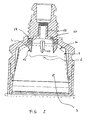
- the extraction device 1 is in the form of an extraction assembly capable of receiving a recharging element 5, in this case in the example illustrated, a capsule semi-rigid containing a substance to be extracted such as a predosed amount of ground and roasted coffee.
- the extraction assembly more precisely comprises a capsule cage forming a hollow body 2 provided with a housing 3 and a support lower 4 capable of cooperating with the capsule cage 2 in closing around the recharging element 5.
- the closure of the capsule cage 2 and of the support lower 4 can be achieved by any suitable mechanical means, but of preferably by relative mobility in a substantially vertical direction, straight or slightly arched, with O trajectory.
- the support lower 4 may be static in direction O to receive the element of refill 5 and the capsule cage can be movable in direction O in position closing.
- the movable lower support can also be provided according to O and the cage with fixed capsule or even mobile according to O.
- the capsule cage 2 is extended upwards by an upper portion 20 having connection means 21 such as an external thread allowing the connection to a hot water supply.
- the upper portion 20 includes an internal bore 22 for the passage of water which communicates in the housing 3 of the hollow body at a water outlet 23.
- the lower support 4 includes a distribution plate 40 for receive the base of the capsule generally consisting of a flexible sheet 50.
- the distribution plate has distributed on its internal surface elements in relief 41 intended to cause opening by tearing multiple of the flexible sheet under the effect of the extraction pressure inside of the capsule. Downstream of the distribution plate is provided a sub-assembly 42 for the flow of the liquid extract obtained, after rupture of the base of the capsule, ending with an outlet orifice 43.
- the charging element has a sealed peripheral edge 51 maintained pinching between the capsule cage 2 and the lower support 4.
- the closure by pinching is carried out in a sealed manner by contact between edges of cage and support.
- Sealing means such as a ring elastomer 52 of the cage, can be provided to ensure a firm pinch and elastic between the parts in contact and thus avoid any risk of leakage during pressurization in the housing.
- Mechanical means ensuring closing and maintaining in the closed position of the assembly are not illustrated here. These may be, for example, means of the knee type with control manual or motorized.
- a series of elements of drilling 6 is provided at the bottom of the housing 3 to cut the top of the capsule according to a plurality of holes and allow the passage of water in the capsule.
- the piercing elements 6 are regularly distributed around the central water supply and protrude towards the interior of the accommodation in a direction substantially parallel to the direction of engagement of the capsule in housing.
- the elements are mounted integrally on a common mounting support 60 allowing quick mounting inside housing.
- the mounting bracket may include a hollow portion of rod 62 having an external thread 63 which screws into a threaded portion complementary to the water inlet channel.
- the drilling elements can be mounted by screws 64 on the support 60. In an alternative, the elements of drilling could be welded to the support or be an integral part of the support.
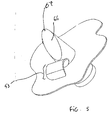
- each piercing member 6 comprises a base portion 65 oriented in a longitudinal direction I corresponding to the direction of engagement in the charging element.
- the basic portion is interrupted by an inclined surface 66 which forms the cutting surface of item.
- the angle of inclination A of the cutting surface relative to the direction I is preferably between 10 and 50 degrees, better still between 15 and 45 degrees.
- the surface 66 essentially has a cutting function such as illustrated in FIG. 5 with the advantageous effect that the material chip 53 is cut neatly and is released in one piece from the side of the part beveled 66. Thus, a tear is avoided as with a point where the matter tends to spread in several directions creating lines of tear around the edge of the hole.
- the basic portion can advantageously be a portion of cone of tapered section towards the cutting surface.
- One such form is advantageous because it guarantees the maintenance of a minimum clearance between the surface of the base portion and the edge of the hole. This prevents backflow of water too brutal which would result in creating privileged paths to through the mass to be extracted and therefore, consequently generate a rise in press too fast.
- Such a truncated cone shape is also advantageous by relative to a shape with constant section in particular when the closing of the device is made along a substantially arcuate trajectory as shown in Figure 1 insofar as a constant section would have the effect of widening the hole on the outer side of the curve and therefore create unwanted play.
- the recharging element expands relatively little during pressurization so that a passage 30 is maintained between the wall of the housing and the wall of the recharging element 5.
- the base portion 65 must have a sufficient length, of the order of 2 to 15 mm, so that when the charging element is engaged in position in the housing, the cutting surface 66 is fully positioned inside the enclosure of the recharging element; and this, taking into account the possible variations of the thickness of the passage, due to the dimensional tolerances between the housing and the charging element.
- each piercing element is oriented individually in the housing so that its cutting surface 66 makes an angle of 90 +/- 5 degrees from the surface to be cut. We thus obtain better cutting and less wear on the cutting surface.
- the drilling elements can be made of suitable hard material and wear resistant.
- the material is chosen according to the material of the cutting capsule or sachet.
- the capsules are made of aluminum thin or plastic 0.2 to 1.5 tenths of a millimeter so that drilling elements may be made of metal, preferably aluminum hard anodized or stainless steel, or ceramic or hard plastic.
- the number of drilling elements can of course vary depending on the size of the charging elements. Sufficient is necessary to correctly distribute the water through the mass without however weakening the wall of the element which could then break and thus soil the housing. So, the number of piercing elements is preferably between 3 and 10, preferably 4 and 6.
- each drilling element can be provided with a groove 67 longitudinally distributed along the surface of the basic portion; allowing to refine the water flow in a way controlled.
- the groove is preferably arranged on the side of the end of the cutting surface so that it is sufficiently clear.
- the method for extracting a liquid is the next.
- the device is in the open position and a capsule 5 is deposited on the raised surface of the lower support 4.
- the device is closed by applying the edges of the cage 2 and the support 4 by pinching the edge of sealing 51 of the capsule.
- the upper surface of the capsule is cut by the piercing elements 6.
- Hot water arrives in the accommodation via outlet 23 and is distributed in passage 30 then flows slowly between the surface of the elements of drilling and cut edges of openings. As the water penetrates, the pressure inside the capsule increases slowly; which tendency to slightly dilate the holes evenly around each element.
- the tear pressure at the base of the capsule reaches approximately 7 to 9 bars in seconds.
- the breaking tension of the capsule sheet is then reached and the extracted liquid can be evacuated through the part flow 42 and through hole 43.
- the invention has been described by way of preferred example in connection with a device for extracting semi-rigid capsules having deformability limited. However, it is understood that the invention applies equally to the extraction of flexible refill elements of the bag type comprising a compacted mass of extractable food substance.
Abstract
Description
L'invention concerne un dispositif d'extraction de substance alimentaire pour la confection de boissons utilisant un élément de recharge fermé chargé en substance alimentaire et traversée par un flux d'eau sous pression.The invention relates to a device for extracting food substance. for making beverages using a closed refill element charged with food substance and crossed by a stream of water under pressure.
L'utilisation de doses prédéterminées et préemballées sous forme d'éléments de recharge contenant du café moulu pour la préparation de boissons du type expresso ou similaire présente de nombreux avantages, entre autres, ceux de faciliter les opérations de préparation de la boisson, d'assurer une préparation relativement propre et de contrôler un dosage et une qualité relativement constante du produit préparé.The use of predetermined doses and prepackaged in the form refill units containing ground coffee for the preparation of espresso or similar drinks have many advantages, among others, those of facilitating the operations of preparation of the drink, of ensuring a relatively clean preparation and to control a dosage and a quality relatively constant of the prepared product.
Le principe d'extraction d'éléments de recharge fermés ou scellés consiste à : (i) enfermer l'élément de recharge dans une enceinte close, (ii) percer une face de l'élément, (iii) introduire une quantité d'eau chaude dans l'élément de façon à créer un environnement sous pression à l'intérieur de l'élément pour produire l'extrait de café (iv) puis libérer l'extrait de café au travers de la face opposée de l'élément de recharge qui au contact de parties saillantes du dispositif s'ouvre sous l'effet de la pression interne.The principle of extracting closed or sealed refill elements consists of to: (i) enclose the recharging element in a closed enclosure, (ii) pierce a face of the element, (iii) introduce a quantity of hot water into the element way to create a pressurized environment inside the element for produce the coffee extract (iv) then release the coffee extract across the face opposite of the charging element which in contact with projecting parts of the device opens under the effect of internal pressure.
Il existe déjà des dispositifs d'extraction de capsules ou de cartouches, comprenant un logement pour la cartouche à extraire et une pointe comme ceux décrits dans les brevets CH 605 293 et EP 242 556. Dans ces dispositifs, la pointe a une double fonctionnalité. D'une part, elle réalise l'ouverture de la partie supérieure de la capsule et d'autre part, elle constitue le canal d'arrivée d'eau en ce sens que l'eau est directement introduite à l'intérieure de la capsule par la pointe elle-même. Un inconvénient d'un tel dispositif provient de ce que le trou obtenu par une aiguille unique a pour effet de créer, au début de l'extraction, un chemin préférentiel au travers de la masse de café à extraire sans la mouiller entièrement. La conséquence de la création d'un chemin privilégié est que lorsque l'extraction se poursuit, la vitesse de montée en pression devient trop rapide ce qui peut conduire à la libération de l'extrait trop tôt de sorte que l'on n'atteint pas un temps d'extraction suffisant. Bien entendu, la conséquence peut être une perte des solides et arômes qui restent alors fixés dans le marc et ne sont donc pas transférés dans l'extrait. Un autre inconvénient provient de ce que la pointe a tendance à s'obstruer rapidement en raison du calcaire de l'eau ou du contact avec le marc ; ce qui peut affecter les performances du dispositif. Compte tenu de la taille importante du trou pratiqué dans la capsule, la capsule est aussi sujette à des remontées indésirables de marc et de résidus liquides après usage.There are already devices for extracting capsules or cartridges, comprising a housing for the cartridge to be extracted and a point like those described in patents CH 605 293 and EP 242 556. In these devices, the tip has a dual functionality. On the one hand, it opens the upper part of the capsule and on the other hand, it constitutes the inlet channel of water in the sense that water is directly introduced into the interior of the capsule by the tip itself. One drawback of such a device is that the hole obtained by a single needle has the effect of creating, at the beginning of extraction, a preferential path through the mass of coffee to be extracted without fully wetting it. The consequence of creating a path privileged is that when the extraction continues, the rate of rise in pressure becomes too fast which can lead to the release of the extract too early so that insufficient extraction time is not achieved. Of course, the consequence may be a loss of solids and aromas which then remain fixed in the marc and are therefore not transferred to the extract. Another downside comes from the fact that the tip tends to clog quickly due to the water scale or contact with the grounds; which can affect device performance. Given the large size of the hole made in the capsule, the capsule is also subject to unwanted spikes in marc and liquid residue after use.
Le document EP 0 604 615 B1 se rapporte, en autre à un dispositif qui comprend des moyens de perforation d'un sachet souple contenant le produit à extraire qui se présente sous la forme d'une grille de répartition d'eau pourvue sur sa face inférieure d'éléments de pointes, lames ou croix saillantes. Des orifices peuvent être pourvus pour le passage de l'eau au travers de la grille de répartition au niveau de chaque moyen de perforation. On apporte ainsi une amélioration de la répartition d'eau dans le sachet ; ce qui permet d'améliorer le mouillage de la masse à extraire. Cependant, les orifices sont susceptibles de s'entartrer à la longue avec des conséquences sur le contrôle du débit et de la pression au cours de l'extraction.The document EP 0 604 615 B1 also relates to a device which comprises means for perforating a flexible bag containing the product to extract which is in the form of a water distribution grid provided on its underside of projecting points, blades or crosses. of the orifices can be provided for the passage of water through the grid distribution at the level of each perforation means. We thus bring a improved water distribution in the bag; which improves the wetting of the mass to be extracted. However, the openings are likely to scaling up in the long run with consequences for flow control and pressure during extraction.
La présente invention vise une amélioration dans la conception des éléments réalisant le perçage d'un élément de recharge fermé du type capsule, sachet ou autres qui favorise les conditions d'écoulement de l'eau à l'intérieur de l'élément de recharge et améliore les conditions d'extractions. Plus précisément, l'invention vise à améliorer l'arrosage en eau au travers de la substance à extraire en évitant les chemins privilégiés et en assurant une montée en pression relativement lente à l'intérieur de l'élément de recharge pour optimiser la capture des arômes. L'invention a aussi pour objet de supprimer le risque de réduction de l'écoulement en raison d'obstructions formés par des dépôts calcaires ou autres. L'invention a aussi pour objet de proposer une configuration de perçage garantissant un écoulement d'eau relativement reproductible d'un élément de recharge à l'autre qui tient compte des variations dues aux tolérances dimensionnelles entre le logement du dispositif et les éléments de recharge. L'invention vise aussi à limiter la remontée de résidus liquides ou solides en dehors de l'élément de recharge après extraction. L'invention a aussi pour objet de garantir une ouverture par les éléments de perçage plus propre et sans risque de détachement de matériau de la paroi de l'élément de recharge.The present invention aims to improve the design of elements piercing a closed refill element of the capsule type, sachet or other which favors the conditions of water flow inside of the recharging element and improves the extraction conditions. More specifically, the invention aims to improve water sprinkling through the substance to be extracted, avoiding privileged paths and ensuring relatively slow pressure build-up inside the charging element to optimize the capture of aromas. The invention also relates to remove the risk of flow reduction due to obstructions formed by limestone or other deposits. The invention also relates to propose a drilling configuration guaranteeing water flow relatively reproducible from one recharging element to another which takes into account variations due to dimensional tolerances between the housing of the device and recharging elements. The invention also aims to limit the rising of liquid or solid residues outside the charging element after extraction. The object of the invention is also to guarantee opening by the cleaner drilling elements without risk of detachment of material the wall of the charging element.
Pour cela, le dispositif selon l'invention comprend un corps creux destiné à recevoir l'élément de recharge, un canal d'arrivée d'eau traversant ledit corps et communiquant dans le logement et une pluralité d'éléments de perçage disposés dans le logement pour percer l'élément de recharge en plusieurs endroits distincts afin de permettre le passage de l'eau dans l'élément de recharge. L'amélioration du dispositif prévoit que les éléments de perçage sont espacés dans le logement par rapport à la direction d'arrivée d'eau. De plus, chaque élément de perçage comprend une portion de base qui est solidaire du corps et fait saillie dans le logement. La portion de base est destinée à s'engager au moins partiellement à l'intérieur de l'élément de recharge de façon à former une surface d'écoulement pour l'eau. La portion de base est intersectée par une surface de découpe selon un angle aigu formant une portion de découpe en biseau.For this, the device according to the invention comprises a hollow body intended receiving the refill element, a water inlet channel passing through said body and communicating in the housing and a plurality of piercing elements arranged in the housing to pierce the charging element in several separate places to allow water to pass through the element refill. The improvement of the device provides that the piercing elements are spaced in the housing relative to the direction of water supply. Moreover, each piercing element comprises a base portion which is integral with the body and protrudes into the housing. The basic portion is intended for engage at least partially inside the charging element so to form a flow surface for water. The base portion is intersected by a cutting surface at an acute angle forming a cutting portion beveled.
Une telle configuration des éléments de perçage a pour effet d'améliorer le mouillage de la substance à extraire en réduisant les chemins privilégiés, permet une montée en pression plus lente à l'intérieur de l'élément de recharge et donc améliore la qualité de l'extrait en substance liquide obtenu. De manière plus spécifique, les découpes sont ainsi réalisées avec une meilleure définition et une meilleure géométrie des ouvertures. Notamment, on obtient des ouvertures qui sont plus resserrées autour des éléments de perçage. Ceci a pour conséquence que l'eau s'écoule au début plus lentement dans l'élément de recharge en évitant de former des chemins privilégiés et aussi, la montée en pression qui s'en suit, se fait de manière plus lente. A la différence d'une simple pointe, l'élément de perçage selon l'invention ne crée pas un repliement de matière sur tout le pourtour de l'ouverture ; ce qui a tendance à l'agrandir, mais au contraire, l'élément de perçage découpe proprement et dégage la matière découpée du côté de la surface de découpe seulement, produisant ainsi une meilleure définition de l'ouverture et donc un effet bénéfique sur la vitesse de montée en pression interne.Such a configuration of the piercing elements has the effect of improving wetting of the substance to be extracted by reducing the preferred paths, allows a slower pressure build-up inside the charging element and therefore improves the quality of the liquid substance extract obtained. So more specific, the cuts are thus carried out with better definition and better geometry of the openings. In particular, we obtain openings that are tighter around the piercing elements. This has consequence that the water flows at the start more slowly in the element of recharging while avoiding forming privileged paths and also, the rise in pressure that follows, is done more slowly. Unlike one single point, the piercing element according to the invention does not create a folding of material all around the opening; which tends to make it bigger, but on the contrary, the piercing element cuts cleanly and releases the material cut from the cutting surface side only, thereby producing a better definition of the aperture and therefore a beneficial effect on the speed internal pressure rise.
De préférence, afin d'obtenir des ouvertures ayant une bonne définition, la surface de découpe de l'élément de perçage forme un angle de découpe compris entre 10 et 50 degrés, et de manière encore plus préférentielle 15 et 45 degrés, par rapport à la direction longitudinale de la portion de base.Preferably, in order to obtain openings having a good definition, the cutting surface of the drilling element forms a cutting angle included between 10 and 50 degrees, and even more preferably 15 and 45 degrees, with respect to the longitudinal direction of the base portion.
De préférence, la portion de base présente une section qui décroít progressivement en direction de la surface de découpe selon un angle inférieur à l'angle de la surface de découpe ce qui permet de contrôler plus précisément l'agrandissement de l'ouverture et assurer ainsi que la matière reste au plus près de la portion de base au fur et à mesure de l'introduction de l'élément de perçage dans l'élément de recharge ; garantissant ensuite une montée en pression plus lente et donc une extraction de meilleure qualité.Preferably, the base portion has a decreasing section gradually towards the cutting surface at a lower angle at the angle of the cutting surface which allows more precise control enlarging the opening and ensuring that the material remains as close as possible of the basic portion as the element of introduction is introduced drilling in the refill element; then guaranteeing a rise in slower pressure and therefore better quality extraction.
La forme de la portion de base n'est pas limitative. Toutefois, on préférera que la portion de base ait une section transversale telle que le rapport de sa plus grande dimension à sa plus étroite dimension soit comprise entre 2/1 et 1/1 de façon à produire des d'ouvertures localisées en forme de trous plutôt que des entailles. Ainsi, la portion de base peut avoir une section de forme circulaire, ellipsoïdale, rectangulaire, carrée, triangulaire ou autre forme de polygones réguliers ou irréguliers.The shape of the basic portion is not limiting. However, we prefer that the base portion has a cross section such that the ratio from its largest dimension to its narrowest dimension is between 2/1 and 1/1 so as to produce localized openings in the form of holes rather only nicks. Thus, the base portion can have a shape section circular, ellipsoidal, rectangular, square, triangular or other form of regular or irregular polygons.
De manière préférée, la portion de base forme une portion de cône d'angle compris entre 1 et 10 degrés, préférentiellement 3 et 5 degrés laquelle est intersectée par la surface de découpe. Ainsi, l'ouverture est agrandie de manière progressive et contrôlée autour de l'élément de perçage et le risque de déchirure est diminué.Preferably, the base portion forms a corner cone portion between 1 and 10 degrees, preferably 3 and 5 degrees which is intersected by the cutting surface. Thus, the opening is enlarged so progressive and controlled around the piercing element and the risk of tearing is decreased.
On a aussi pu remarquer que l'orientation de l'élément de perçage, et notamment sa surface de découpe, dans le logement a une importance sur la propreté de la découpe. Ainsi, les éléments de perçage sont préférablement orientés dans le logement de façon à présenter leur surface de découpe respective selon un angle proche ou égal à 90 degrés par rapport à la surface de l'élément de recharge à découper lorsque celui-ci est engagé dans le logement. Autrement dit, l'angle d'attaque est orienté de manière à être maximal et favorise ainsi une découpe plus performante.It has also been noted that the orientation of the piercing element, and especially its cutting surface, in the housing has an importance on the clean cutting. Thus, the drilling elements are preferably oriented in the housing so as to present their cutting surface respective at an angle close to or equal to 90 degrees to the surface of the charging element to be cut when it is engaged in the housing. In other words, the angle of attack is oriented so as to be maximum and thus promotes a more efficient cutting.
Bien entendu, la nature et la géométrie de l'élément de recharge peuvent recouvrir de nombreuses variantes. En général, le corps du dispositif possède un logement de forme et dimensions adaptées à recevoir un ou plusieurs types d'éléments de recharge. L'élément de recharge peut être un élément rigide, semi-rigide ou souple comprenant une substance à extraire sous forme compactée ou non. A titre d'exemple, le type d'élément de recharge est une capsule ou cartouche imperméable, scellée, comprenant une coupelle sensiblement en forme de tronc de cône et une face inférieure formant un opercule scellé sur le rebord inférieur de la coupelle comme celle faisant l'objet du brevet EP 512 468 dont le contenu est incorporé ici par référence. Selon une autre variante possible, il peut s'agir d'un sachet souple formé de deux feuilles souples soudées entre elles sur leur pourtour et comprenant une portion compactée de substance à extraire. Une telle configuration de sachet est décrite dans les brevets US 6025000 et US6068871 incorporés ici par référence.Of course, the nature and the geometry of the recharging element can cover many variations. In general, the device body has a housing of shape and dimensions adapted to receive one or more types recharging elements. The recharging element can be a rigid element, semi-rigid or flexible comprising a substance to be extracted in the form compacted or not. For example, the type of charging element is a waterproof capsule or cartridge, sealed, including a cup substantially in the shape of a truncated cone and a lower face forming a seal on the lower edge of the cup like the one of patent EP 512 468, the content of which is incorporated herein by reference. According to one another possible variant, it can be a flexible bag formed by two sheets flexible welded together around their periphery and comprising a portion compacted with substance to be extracted. Such a bag configuration is described in patents US 6025000 and US6068871 incorporated here by reference.
Le corps du dispositif pour la réception de l'élément recharge selon l'invention peut faire partie d'un ensemble complet du type machine à café expresso ou similaire. Le corps peut être partie intégrante du dispositif ou être une partie rapportée par vis ou autres moyens. Le corps est en général communément appelé "cage à capsule". En général, le corps du dispositif coopère en fermeture avec une partie inférieure de fermeture complémentaire comprenant des moyens de rupture de la partie inférieure de l'élément de recharge pour l'écoulement de l'extrait produit lors de l'opération d'extraction. Selon l'invention, le corps et la partie inférieure de fermeture coopèrent en fermeture selon un principe de mâchoires mobiles dans une direction sensiblement correspondante à la direction des éléments de perçage dans le logement de façon à éviter tout risque de déchirement de l'élément de recharge. Un dispositif à mâchoire mobile de ce type est décrit dans la demande de brevet EP 0604 615 ou encore dans la demande de brevet non encore publiée EP No. 99117107.5 du 31.08.1999 au nom de la demanderesse; le contenu intégral des deux demandes étant aussi inclus ici par référence.The body of the device for receiving the refill element according to the invention can be part of a complete set of the coffee machine type espresso or similar. The body can be an integral part of the device or be a part attached by screw or other means. The body is generally commonly known as a "capsule cage". In general, the body of the device cooperates in closing with a complementary lower closing part comprising means for breaking the lower part of the element refill for the flow of the extract produced during the extraction operation. According to the invention, the body and the lower closure part cooperate in closing on the principle of movable jaws in one direction substantially corresponding to the direction of the piercing elements in the housing so as to avoid any risk of tearing of the charging element. A movable jaw device of this type is described in the patent application EP 0604 615 or also in the patent application not yet published EP No. 99117107.5 dated 31.08.1999 in the name of the plaintiff; the full content of two requests are also included here by reference.
La suite de la description est faite en référence aux dessins dans lesquels :
Dans la présente demande le terme "capsule" peut être employé pour désigner l'élément de recharge. Il ne doit pas toutefois être interprété de manière limitative et peut inclure tout type d'élément de recharge rigide, semi-rigide ou souple.In the present application the term "capsule" can be used to designate the charging element. However, it should not be interpreted limitatively and may include any type of rigid, semi-rigid charging element or flexible.
En référence avec la figure 1, le dispositif d'extraction 1 selon l'invention
se présente sous la forme d'un ensemble d'extraction capable de recevoir un
élément de recharge 5, en l'occurrence dans l'exemple illustré, une capsule
semi-rigide contenant une substance à extraire telle qu'une quantité prédosée de
café moulu et torréfié. L'ensemble d'extraction comprend plus précisément une
cage à capsule formant un corps creux 2 muni d'un logement 3 et un support
inférieur 4 capable de coopérer avec la cage à capsule 2 en fermeture autour de
l'élément de recharge 5. La fermeture de la cage à capsule 2 et du support
inférieur 4 peut être réalisé par tout moyen mécanique approprié, mais de
préférence, par mobilité relative selon une direction sensiblement verticale,
rectiligne ou faiblement arquée, de trajectoire O. A titre d'exemple, le support
inférieur 4 peut-être statique dans la direction O pour recevoir l'élément de
recharge 5 et la cage à capsule peut être mobile dans la direction O en position
de fermeture. Alternativement, on peut aussi prévoir le support inférieur mobile
selon O et la cage à capsule fixe ou encore mobile selon O.With reference to FIG. 1, the
La cage à capsule 2 se prolonge vers le haut par une portion supérieure 20
présentant des moyens de connexion 21 tels qu'un filetage externe permettant le
raccordement à une alimentation en eau chaude. La portion supérieure 20
comprend un alésage interne 22 pour le passage de l'eau qui communique dans
le logement 3 du corps creux au niveau d'une sortie d'eau 23.The
Le support inférieur 4 comprend une plaque de répartition 40 pour
recevoir la base de la capsule généralement constituée d'une feuille souple 50.
La plaque de répartition comprend de manière répartie sur sa surface interne
des éléments en reliefs 41 destinés à provoquer l'ouverture par déchirement
multiple de la feuille souple sous l'effet de la pression d'extraction à l'intérieur
de la capsule. En aval de la plaque de répartition est prévu un sous-ensemble
42 pour l'écoulement de l'extrait liquide obtenu, après rupture de la base de la
capsule, se terminant par un orifice de sortie 43.The
L'élément de recharge possède un bord périphérique scellé 51 maintenu
en pincement entre la cage à capsule 2 et le support inférieur 4. La fermeture
par pincement est réalisée de manière étanche par un contact entre des bords de
de la cage et du support . Des moyens d'étanchéité, tels qu'une bague
élastomère 52 de la cage, peuvent être prévus pour assurer un pincement ferme
et élastique entre les parties en contact et éviter ainsi tout risque de fuite lors de
la mise en pression dans le logement. Les moyens mécaniques assurant la
fermeture et le maintien en position fermée de l'ensemble ne sont pas illustrés
ici. Il peut s'agir, par exemple, de moyens du type à genouillère à commande
manuelle ou motorisée.The charging element has a sealed
Comme le montre plus précisément la figure 2, une série d'éléments de
perçage 6 est prévue au fond du logement 3 pour découper le dessus de la
capsule selon une pluralité de trous et permettre le passage de l'eau dans la
capsule. Les éléments de perçage 6 sont régulièrement répartis autour de
l'arrivée d'eau centrale et font saillie vers l'intérieur du logement dans une
direction sensiblement parallèle à la direction d'engagement de la capsule dans
le logement. De préférence, les éléments sont montés de manière solidaire sur
un support de montage commun 60 permettant un montage rapide à l'intérieur
du logement. Le support de montage peut comprendre une portion creuse de
tige 62 comportant un filetage externe 63 qui se visse dans une portion filetée
complémentaire du canal d'arrivée d'eau. Les éléments de perçage peuvent être
montés par des vis 64 sur le support 60. Dans une alternative, les éléments de
perçage pourraient être soudés sur le support ou faire partie intégrante du
support.As shown more precisely in Figure 2, a series of elements of
Comme le montre la figure 3, chaque élément de perçage 6 comprend une
portion de base 65 orientée selon une direction longitudinale I correspondant à
la direction d'engagement dans l'élément de recharge. La portion de base est
interrompue par une surface inclinée 66 qui forme la surface de découpe de
l'élément. L'angle d'inclinaison A de la surface de découpe par rapport à la
direction I est de préférence compris entre 10 et 50 degrés, mieux encore entre
15 et 45 degrés. La surface 66 a essentiellement une fonction de découpe telle
que l'illustre la figure 5 avec pour effet avantageux que le copeau de matière 53
est découpé de manière nette et est dégagé d'un seul tenant du côté de la partie
biseautée 66. Ainsi, on évite un déchirement comme avec une pointe où la
matière a tendance à s'écarter selon plusieurs directions créant des lignes de
déchirure sur le pourtour du trou.As shown in Figure 3, each piercing
La portion de base peut avantageusement être une portion de cône de section effilée en direction de la surface de découpe. Une telle forme est avantageuse car elle permet de garantir le maintien d'un jeu minimum entre la surface de la portion de base et le bord du trou. On évite ainsi une rentrée d'eau trop brutale ce qui aurait pour conséquence de créer des chemins privilégiés au travers de la masse à extraire et donc, par conséquent engendrer une montée en pression trop rapide. Une telle forme en tronc de cône est aussi avantageuse par rapport à une forme à section constante en particulier lorsque la fermeture du dispositif se fait selon une trajectoire sensiblement arquée comme représentée à la figure 1 dans la mesure où une section constante aurait pour effet d'élargir le trou du côté externe à la courbe et donc de créer un jeu indésirable.The basic portion can advantageously be a portion of cone of tapered section towards the cutting surface. One such form is advantageous because it guarantees the maintenance of a minimum clearance between the surface of the base portion and the edge of the hole. This prevents backflow of water too brutal which would result in creating privileged paths to through the mass to be extracted and therefore, consequently generate a rise in press too fast. Such a truncated cone shape is also advantageous by relative to a shape with constant section in particular when the closing of the device is made along a substantially arcuate trajectory as shown in Figure 1 insofar as a constant section would have the effect of widening the hole on the outer side of the curve and therefore create unwanted play.
Dans l'exemple illustré, l'élément de recharge s'expanse relativement peu
lors de la mise en pression de sorte qu'un passage 30 est maintenu entre la paroi
du logement et la paroi de l'élément de recharge 5. Ainsi, la portion de base 65
doit avoir une longueur suffisante, de l'ordre de 2 à 15 mm, de sorte que
lorsque l'élément de recharge est engagé en position dans le logement, la
surface de découpe 66 est entièrement positionnée à l'intérieur de l'enceinte de
l'élément de recharge ; et ce, en tenant compte des variations possibles de
l'épaisseur du passage, dues aux tolérance dimensionnelles entre le logement et
l'élément de recharge.In the example illustrated, the recharging element expands relatively little
during pressurization so that a
Comme le montre la figure 2, chaque élément de perçage est orienté
individuellement dans le logement de sorte que sa surface de découpe 66 fasse
un angle de 90 +/- 5 degrés par rapport à la surface à découper. On obtient ainsi
une meilleure découpe et une moindre usure de la surface de découpe.As shown in Figure 2, each piercing element is oriented
individually in the housing so that its cutting
Les éléments de perçage peuvent être réalisés en matériau approprié dur et résistant à l'usure. Le matériau est choisi en fonction du matériau de la capsule ou sachet à découper. En général, les capsules sont en aluminium mince ou en plastique de 0,2 à 1,5 dixième de millimètre de sorte que les éléments de perçage peuvent être en métal, de préférence, en aluminium anodisé couche dure ou acier inoxydable, ou encore en céramique ou en plastique dur.The drilling elements can be made of suitable hard material and wear resistant. The material is chosen according to the material of the cutting capsule or sachet. In general, the capsules are made of aluminum thin or plastic 0.2 to 1.5 tenths of a millimeter so that drilling elements may be made of metal, preferably aluminum hard anodized or stainless steel, or ceramic or hard plastic.
Le nombre d'éléments de perçage peut bien entendu varier en fonction de la taille de l'éléments de recharge. Un nombre suffisant est nécessaire pour correctement repartir l'eau au travers de la masse sans toutefois trop fragiliser la paroi de l'élément qui pourrait alors rompre et ainsi souiller le logement. Ainsi, le nombre des éléments de perçage est de préférence compris entre 3 et 10, de préférence 4 et 6.The number of drilling elements can of course vary depending on the size of the charging elements. Sufficient is necessary to correctly distribute the water through the mass without however weakening the wall of the element which could then break and thus soil the housing. So, the number of piercing elements is preferably between 3 and 10, preferably 4 and 6.
Dans une configuration possible, chaque élément de perçage peut être
muni d'une rainure 67 longitudinalement distribuée le long de la surface de la
portion de base ; permettant d'affiner l'écoulement d'eau d'une manière
contrôlée. La rainure est préférablement disposée du côté de l'extrémité de la
surface de découpe de sorte qu'elle soit suffisamment dégagée.In one possible configuration, each drilling element can be
provided with a
Dans l'exemple présenté, la méthode pour extraire un liquide est la
suivante. Le dispositif se trouve en position ouverte et une capsule 5 est
déposée sur la surface en relief du support inférieur 4. Le dispositif est refermé
par application des bords de la cage 2 et du support 4 en pinçant le bord de
scellage 51 de la capsule. Lors de la fermeture, la surface supérieure de la
capsule est découpée par les éléments de perçage 6. Dans cette position, une
partie significative de la portion de base de chaque élément est introduite dans
la capsule de façon à offrir une surface d'écoulement pendant le temps
d'extraction. L'eau chaude arrive dans le logement par la sortie 23 et se réparti
dans le passage 30 puis s'écoule lentement entre la surface des éléments de
perçage et les bords découpés des ouvertures. Au fur et à mesure que l'eau
pénètre, la pression à l'intérieur de la capsule augmente lentement ; ce qui a
tendance à légèrement dilater les trous de manière homogène autour de chaque
élément. La pression à la déchirure de la base de la capsule atteint environ 7 à
9 bars en quelques secondes. La tension de rupture de la feuille de la capsule
est alors atteinte et le liquide extrait peut s'évacuer au travers de la partie
d'écoulement 42 et par le trou 43.In the example presented, the method for extracting a liquid is the
next. The device is in the open position and a
L'invention a été décrite à titre d'exemple préférentiel en rapport avec un dispositif pour l'extraction de capsules semi-rigide ayant une déformabilité limitée. Cependant, il est entendu, que l'invention s'applique tout autant pour l'extraction d'éléments de recharge souples du type sachets comprenant une masse compactée d'une subtance alimentaire extractable.The invention has been described by way of preferred example in connection with a device for extracting semi-rigid capsules having deformability limited. However, it is understood that the invention applies equally to the extraction of flexible refill elements of the bag type comprising a compacted mass of extractable food substance.
Claims (9)
Priority Applications (28)
| Application Number | Priority Date | Filing Date | Title |
|---|---|---|---|
| EP00203855A EP1203554A1 (en) | 2000-11-03 | 2000-11-03 | Device for extracting food material stored in a reloading cartridge |
| HU0400518A HUP0400518A2 (en) | 2000-11-03 | 2001-10-04 | Device and method for improving extraction of a food substance contained in a refill element |
| SK529-2003A SK5292003A3 (en) | 2000-11-03 | 2001-10-04 | Device for improving extraction of a food substance contained in a refill element |
| AU2002220589A AU2002220589B2 (en) | 2000-11-03 | 2001-10-04 | Device for improving extraction of a food substance contained in a refill element |
| DK01992517T DK1339305T3 (en) | 2000-11-03 | 2001-10-04 | Device and method for improving the extraction of a food substance contained in a refill element |
| SI200120059A SI21167A (en) | 2000-11-03 | 2001-10-04 | Device and process for improving extraction of a food substance contained in a refill element |
| MXPA03004923A MXPA03004923A (en) | 2000-11-03 | 2001-10-04 | Device for improving extraction of a food substance contained in a refill element. |
| RU2003116237/12A RU2277840C2 (en) | 2000-11-03 | 2001-10-04 | Apparatus and method for improved extraction of food substance contained in disposable member |
| PT01992517T PT1339305E (en) | 2000-11-03 | 2001-10-04 | Device for improving extraction of a food substance contained in a refill element |
| APAP/P/2003/002786A AP2003002786A0 (en) | 2000-11-03 | 2001-10-04 | Device for improving extraction of a food substance contained in a refill element |
| EP01992517A EP1339305B1 (en) | 2000-11-03 | 2001-10-04 | Device for improving extraction of a food substance contained in a refill element |
| PCT/EP2001/011486 WO2002035977A1 (en) | 2000-11-03 | 2001-10-04 | Device for improving extraction of a food substance contained in a refill element |
| BR0115114-2A BR0115114A (en) | 2000-11-03 | 2001-10-04 | Device and method for improving the extraction of a food substance contained in a refill element |
| AU2058902A AU2058902A (en) | 2000-11-03 | 2001-10-04 | Device for improving extraction of a food substance contained in a refill element |
| CA002426840A CA2426840C (en) | 2000-11-03 | 2001-10-04 | Device for improving extraction of a food substance contained in a refill element |
| ES01992517T ES2283457T3 (en) | 2000-11-03 | 2001-10-04 | DEVICE AND METHOD FOR IMPROVING THE REMOVAL OF A FOOD SUBSTANCE CONTAINED IN A RECHARGE ELEMENT. |
| DE60127990T DE60127990T2 (en) | 2000-11-03 | 2001-10-04 | DEVICE AND METHOD FOR IMPROVING THE EXTRACTION OF A FOOD FOUND IN A RECYCLING CARTRIDGE |
| CN01818487.1A CN1243502C (en) | 2000-11-03 | 2001-10-04 | Device and method for improving extraction of food substance contained in refill element |
| AT01992517T ATE359733T1 (en) | 2000-11-03 | 2001-10-04 | APPARATUS AND METHOD FOR IMPROVING THE EXTRACTION OF A FOOD CONTAINED IN A RELOADING CARTRIDGE |
| PL365730A PL196425B1 (en) | 2000-11-03 | 2001-10-04 | Device for improving extraction of a food substance contained in a refill element |
| OA1200300127A OA12408A (en) | 2000-11-03 | 2001-10-04 | Device and method for improving the extraction of a food substance contained in a charging element |
| JP2002538795A JP3875191B2 (en) | 2000-11-03 | 2001-10-04 | Device for extracting food contained in refill containers |
| IL15558601A IL155586A0 (en) | 2000-11-03 | 2001-10-04 | Device for improving extraction of a food substance contained in a refill element |
| IL155586A IL155586A (en) | 2000-11-03 | 2003-04-27 | Device for improving extraction of a food substance contained in a refill element |
| US10/424,736 US6854378B2 (en) | 2000-11-03 | 2003-04-29 | Device and method for improving the extraction of a food substance contained in a refill |
| NO20031993A NO20031993L (en) | 2000-11-03 | 2003-05-02 | Device for improving the retrieval of a nutrient substance contained in ether filler element |
| MA27135A MA25920A1 (en) | 2000-11-03 | 2003-05-02 | DEVICE AND METHOD FOR IMPROVING THE EXTRACTION OF A FOOD SUBSTANCE CONTAINED IN A REFILL ELEMENT. |
| ZA200304307A ZA200304307B (en) | 2000-11-03 | 2003-06-02 | Device for improving extraction of a food substance contained in a refill element. |
Applications Claiming Priority (1)
| Application Number | Priority Date | Filing Date | Title |
|---|---|---|---|
| EP00203855A EP1203554A1 (en) | 2000-11-03 | 2000-11-03 | Device for extracting food material stored in a reloading cartridge |
Publications (1)
| Publication Number | Publication Date |
|---|---|
| EP1203554A1 true EP1203554A1 (en) | 2002-05-08 |
Family
ID=8172224
Family Applications (2)
| Application Number | Title | Priority Date | Filing Date |
|---|---|---|---|
| EP00203855A Withdrawn EP1203554A1 (en) | 2000-11-03 | 2000-11-03 | Device for extracting food material stored in a reloading cartridge |
| EP01992517A Expired - Lifetime EP1339305B1 (en) | 2000-11-03 | 2001-10-04 | Device for improving extraction of a food substance contained in a refill element |
Family Applications After (1)
| Application Number | Title | Priority Date | Filing Date |
|---|---|---|---|
| EP01992517A Expired - Lifetime EP1339305B1 (en) | 2000-11-03 | 2001-10-04 | Device for improving extraction of a food substance contained in a refill element |
Country Status (25)
| Country | Link |
|---|---|
| US (1) | US6854378B2 (en) |
| EP (2) | EP1203554A1 (en) |
| JP (1) | JP3875191B2 (en) |
| CN (1) | CN1243502C (en) |
| AP (1) | AP2003002786A0 (en) |
| AT (1) | ATE359733T1 (en) |
| AU (2) | AU2058902A (en) |
| BR (1) | BR0115114A (en) |
| CA (1) | CA2426840C (en) |
| DE (1) | DE60127990T2 (en) |
| DK (1) | DK1339305T3 (en) |
| ES (1) | ES2283457T3 (en) |
| HU (1) | HUP0400518A2 (en) |
| IL (2) | IL155586A0 (en) |
| MA (1) | MA25920A1 (en) |
| MX (1) | MXPA03004923A (en) |
| NO (1) | NO20031993L (en) |
| OA (1) | OA12408A (en) |
| PL (1) | PL196425B1 (en) |
| PT (1) | PT1339305E (en) |
| RU (1) | RU2277840C2 (en) |
| SI (1) | SI21167A (en) |
| SK (1) | SK5292003A3 (en) |
| WO (1) | WO2002035977A1 (en) |
| ZA (1) | ZA200304307B (en) |
Cited By (6)
| Publication number | Priority date | Publication date | Assignee | Title |
|---|---|---|---|---|
| EP1510160A1 (en) | 2003-08-25 | 2005-03-02 | Nestec S.A. | Method and apparatus for making a beverage from a cartridge containing a substance |
| EP1510158A1 (en) | 2003-08-25 | 2005-03-02 | Nestec S.A. | Apparatus and method for the preparation of a beverage from an ingredient contained in a cartridge |
| WO2009090201A1 (en) * | 2008-01-15 | 2009-07-23 | Nestec S.A. | Sealing adapter for a beverage extraction system suitable for preparing a beverage from cartridges |
| WO2010137954A1 (en) | 2009-06-17 | 2010-12-02 | Sara Lee/De N.V. | Capsule, system and method for preparing a predetermined quantity of beverage suitable for consumption |
| WO2015022342A1 (en) * | 2013-08-13 | 2015-02-19 | Nestec S.A. | Capsule multi-piercer with assembly means |
| US9113746B2 (en) | 2009-07-23 | 2015-08-25 | Ethical Coffee Company Sa | Device for preparing a drink extracted from a capsule |
Families Citing this family (88)
| Publication number | Priority date | Publication date | Assignee | Title |
|---|---|---|---|---|
| US7640843B2 (en) | 2003-01-24 | 2010-01-05 | Kraft Foods R & D, Inc. | Cartridge and method for the preparation of beverages |
| ITTO20040442A1 (en) | 2004-06-29 | 2004-09-29 | Sgl Italia Srl | PERCOLATING MACHINE FOR THE PREPARATION OF A DRINK THROUGH THE USE OF A SEALED CAPSULES CONTAINING ANHYDROUS POWDER MATERIAL. |
| ES2297791T3 (en) | 2004-10-25 | 2008-05-01 | Nestec S.A. | CAPSULE WITH HERMETIC CLOSURE MEDIA. |
| HUP0700822A3 (en) * | 2005-02-07 | 2011-02-28 | Nestec Sa | Device for preparing a drink from a capsule by injection of a pressurized fluid and capsule-holder adapted therefore |
| ITMI20050787A1 (en) * | 2005-04-29 | 2006-10-30 | Illycaffe Spa | PORTAFILTER PARTICULARLY FOR ESPRESSO COFFEE MACHINES |
| US9844292B2 (en) | 2009-10-30 | 2017-12-19 | Adrian Rivera | Coffee maker with multi and single cup modes |
| US7807209B1 (en) | 2005-08-31 | 2010-10-05 | Milne Fruit Products, Inc. | Watermelon juice products and food products produced with the juice products |
| EP1767129B2 (en) * | 2005-09-27 | 2016-10-26 | Nestec S.A. | Extraction module for a capsule-based beverage production device |
| EP1792849A1 (en) * | 2005-12-02 | 2007-06-06 | Tuttoespresso S.p.a. | Pressure beverage cartridge and preparation method |
| PT1839543E (en) | 2006-03-31 | 2008-07-23 | Nestec Sa | Capsule with outer sealing material pressurized by a fluid |
| NL1032085C2 (en) * | 2006-04-19 | 2007-10-22 | Sara Lee De Nv | System for preparing a drink suitable for consumption, as well as exchangeable holder for such a system and method for manufacturing the exchangeable holder. |
| CN101432118B (en) * | 2006-04-24 | 2012-11-07 | 雀巢产品技术援助有限公司 | Capsule for preparing a beverage with a sealing member for water tightness attached thereto and method of producing the same |
| DE202007019239U1 (en) * | 2006-09-26 | 2011-05-19 | Nestec S.A. | Extraction system for the preparation of a beverage from a capsule or cartridge |
| TW201718635A (en) * | 2007-03-06 | 2017-06-01 | 安美基公司 | Variant activin receptor polypeptides and uses thereof |
| PT1967099E (en) | 2007-03-06 | 2011-01-25 | Nestec Sa | Device for preparing a food liquid from a capsule |
| RU2479242C2 (en) | 2007-06-05 | 2013-04-20 | Нестек С.А. | System for capsules, device and method for containerised food liquid preparation by way of centrifugation |
| PL2155019T3 (en) | 2007-06-05 | 2011-09-30 | Nestec Sa | Method for preparing a beverage or liquid food |
| AU2008258543B2 (en) | 2007-06-05 | 2014-04-10 | Société des Produits Nestlé S.A. | Capsule and method for preparing a food liquid by centrifugation |
| US8431175B2 (en) | 2007-06-05 | 2013-04-30 | Nestec S.A. | Method for preparing a beverage or food liquid and system using brewing centrifugal force |
| MX2009013226A (en) | 2007-06-05 | 2010-01-25 | Nestec Sa | Single-use capsule for preparing a food liquid by centrifugation. |
| ITMO20070241A1 (en) * | 2007-07-20 | 2009-01-21 | Saeco Ipr Ltd | DEVICE FOR DRILLING PORTIONED CAPS |
| ATE540881T1 (en) * | 2007-09-03 | 2012-01-15 | Psr Profitable Strategic Redeployment Sarl | CAPSULE FOR PREPARING A DRINK |
| DE102007049601B4 (en) * | 2007-10-16 | 2013-05-23 | Kraft Foods R & D, Inc. | Vending machine with sealing component at the tapping device |
| ITMO20070323A1 (en) * | 2007-10-22 | 2009-04-23 | Illycaffe Spa | CONTAINER |
| PL2071988T3 (en) * | 2007-12-18 | 2011-07-29 | Nestec Sa | Device for preparing a beverage with removable injection member |
| US8359969B2 (en) * | 2008-03-31 | 2013-01-29 | Whirlpool Corporation | Apparatus, method and kit for retrofitting an indoor water dispenser of an existing refrigerator |
| US9981839B2 (en) * | 2008-05-29 | 2018-05-29 | Whirlpool Corporation | Apparatuses and methods for a refrigerator having liquid conditioning and enhancement components for enhanced beverage dispensing |
| US9556011B2 (en) * | 2008-05-29 | 2017-01-31 | Whirlpool Corporation | Apparatuses and methods for a refrigerator having liquid conditioning and enhancement components for enhanced beverage dispensing |
| EP2133008A1 (en) * | 2008-06-09 | 2009-12-16 | Tchibo GmbH | Brewing chamber and brewing device with such a brewing chamber |
| JP5368564B2 (en) | 2008-09-02 | 2013-12-18 | ネステク ソシエテ アノニム | Method for preparing liquid food contained in capsules by centrifugation and system suitable for this method |
| BRPI0918498A8 (en) | 2008-09-02 | 2016-07-19 | Nestec Sa | beverage production device and system, and process for preparing an edible liquid |
| KR20110096568A (en) | 2008-12-09 | 2011-08-30 | 네스텍 소시에테아노님 | Liquid food preparation system for preparing a liquid food by centrifugation |
| HUE027204T2 (en) | 2009-04-15 | 2016-08-29 | Luna Tech Systems Lts Gmbh | Method for manufacturing a capsule for an extraction product |
| CA2765388C (en) * | 2009-06-17 | 2017-09-19 | Sara Lee/De B.V. | Capsule, system and method for the preparation of a beverage and a method for manufacturing such a capsule |
| EP2263501B1 (en) * | 2009-06-17 | 2015-11-25 | Nestec S.A. | Opening means for a capsule-based beverage preparation device |
| IT1397068B1 (en) * | 2009-06-24 | 2012-12-28 | Swiss Caffe Asia Ltd | DRILLING DEVICE, PARTICULARLY FOR CAPSULES FOR THE PREPARATION OF BEVERAGES AND THE LIKE. |
| HUE025499T2 (en) | 2009-08-19 | 2016-04-28 | Nestec Sa | Capsule for the preparation of a coffee extract having a structure facilitating perforation for injection of water |
| US8658232B2 (en) | 2009-08-28 | 2014-02-25 | Nestec S.A. | Capsule system for the preparation of beverages by centrifugation |
| ES2395510T5 (en) | 2010-04-07 | 2020-06-12 | Nestle Sa | Extraction system for the production of a beverage using a capsule |
| CN103025216B (en) | 2010-06-28 | 2016-03-30 | 雀巢产品技术援助有限公司 | Capsule sensor-based system |
| USD637484S1 (en) | 2010-09-02 | 2011-05-10 | Keurig, Incorporated | Beverage cartridge |
| US8361527B2 (en) | 2010-09-02 | 2013-01-29 | Keurig, Incorporated | Beverage cartridge |
| USD647398S1 (en) | 2010-09-02 | 2011-10-25 | Keurig Incorporated | Beverage cartridge |
| USD647399S1 (en) | 2010-09-02 | 2011-10-25 | Keurig, Incorporated | Beverage cartridge |
| US9428328B2 (en) | 2011-09-01 | 2016-08-30 | 2266170 Ontario Inc. | Beverage capsule |
| EP2633789A1 (en) | 2012-02-28 | 2013-09-04 | Nestec S.A. | Beverage preparation machine with drop management |
| ITVR20120044A1 (en) | 2012-03-14 | 2013-09-15 | Coffee Star S A | DRINK PRODUCTION SYSTEM |
| CA2870385A1 (en) * | 2012-04-24 | 2013-10-31 | Nestec S.A. | A capsule holder for a beverage preparation machine |
| EP2906087B1 (en) | 2012-10-09 | 2016-08-31 | Nestec S.A. | Beverage production device with perforating means and method for extracting a beverage from such device |
| WO2014056810A1 (en) | 2012-10-09 | 2014-04-17 | Nestec S.A. | Extraction unit with a shiftable multi-size cartridge receiver |
| CA2889979A1 (en) | 2012-10-09 | 2014-04-17 | Nestec S.A. | Extraction unit with multi-size cartridge cavity |
| EP2730523B1 (en) | 2012-11-12 | 2016-04-06 | 2266170 Ontario, Inc. | Beverage capsule and process and system for making same |
| EP2934243B1 (en) | 2012-12-19 | 2020-03-25 | Société des Produits Nestlé S.A. | Self-locking multi-size cartridge extraction unit |
| US9700171B2 (en) | 2013-04-03 | 2017-07-11 | 2266170 Ontario Inc. | Capsule machine and components |
| CN107259963A (en) * | 2013-05-10 | 2017-10-20 | 竹斯柔公司 | Squeeze the juice system and method |
| EP3656259B1 (en) | 2013-05-17 | 2022-11-09 | Koninklijke Douwe Egberts B.V. | Capsule and method for forming a beverage |
| US10154752B2 (en) | 2013-05-23 | 2018-12-18 | 2266170 Ontario Inc. | Capsule housing |
| US10611507B2 (en) | 2013-08-20 | 2020-04-07 | 2266170 Ontario Inc. | Capsule with control member |
| US10314319B2 (en) * | 2013-11-20 | 2019-06-11 | 2266170 Ontario Inc. | Method and apparatus for accelerated or controlled degassing of roasted coffee |
| EP3089639B1 (en) | 2014-01-03 | 2018-07-11 | Koninklijke Douwe Egberts B.V. | Exchangeable supply pack for a beverage dispensing machine, doser, pump assembly and method of manufacturing. |
| US10336531B2 (en) | 2014-03-21 | 2019-07-02 | 2266170 Ontario Inc. | Capsule with steeping chamber |
| CN106998940B (en) | 2014-11-27 | 2020-04-28 | 雀巢产品有限公司 | Liquid dispensing machine with compact drop stop |
| EP3223669B1 (en) | 2014-11-27 | 2020-02-19 | Société des Produits Nestlé S.A. | Liquid dispensing machine with manual drop stop |
| US20160297659A1 (en) | 2015-04-13 | 2016-10-13 | The Richards Corporation | Capsule opener device |
| RU2733829C2 (en) | 2015-05-15 | 2020-10-07 | Конинклейке Дауве Егбертс Б.В. | Capsule, a system for preparing a beverage suitable for drinking from a similar capsule and use of such capsule in a beverage preparation device |
| PT3134332T (en) | 2015-05-15 | 2019-09-30 | Douwe Egberts Bv | A capsule, a system for preparing a potable beverage from such a capsule and use of such a capsule in a beverage preparation device |
| EP3134330B1 (en) | 2015-05-15 | 2019-06-05 | Koninklijke Douwe Egberts B.V. | A capsule, a system for preparing a potable beverage from such a capsule and use of such a capsule in a beverage preparation device |
| BR112017024464B1 (en) | 2015-05-15 | 2022-02-15 | Koninklijke Douwe Egberts B.V. | CAPSULE, SYSTEM FOR PREPARING A DRINKING BEVERAGE FROM A CAPSULE, USE OF A CAPSULE, AND METHOD FOR MANUFACTURING A BODY OF A CAPSULE |
| WO2016186490A1 (en) | 2015-05-15 | 2016-11-24 | Koninklijke Douwe Egberts B.V. | A capsule, a system for preparing a potable beverage from such a capsule and use of such a capsule in a beverage preparation device. |
| AU2016264690A1 (en) | 2015-05-15 | 2017-12-14 | Koninklijke Douwe Egberts B.V. | A capsule, a system for preparing a potable beverage from such a capsule and use of such a capsule in a beverage preparation device |
| PT3307647T (en) | 2015-06-10 | 2019-10-28 | K Fee System Gmbh | Capsule with a three layer fleece |
| TN2018000084A1 (en) * | 2015-09-18 | 2019-07-08 | K Fee System Gmbh | Adapter for a single serve capsule |
| PT3368447T (en) | 2015-10-27 | 2020-05-07 | Douwe Egberts Bv | Capsule, system and method for preparing a beverage |
| NL2016780B1 (en) | 2016-05-13 | 2017-11-16 | Douwe Egberts Bv | A capsule, a system for preparing a potable beverage from such a capsule and use of such a capsule in a beverage preparation device |
| NL2016779B1 (en) | 2016-05-13 | 2017-11-16 | Douwe Egberts Bv | A capsule and a system for preparing a potable beverage from such a capsule |
| NL2019254B9 (en) | 2016-10-07 | 2018-09-10 | Douwe Egberts Bv | A capsule, a system for preparing a potable beverage from such a capsule and use of such a capsule in a beverage preparation device |
| WO2018069266A1 (en) | 2016-10-11 | 2018-04-19 | Nestec Sa | Liquid dispensing machine with drop stop |
| CA3034163A1 (en) | 2016-10-11 | 2018-04-19 | Nestec S.A. | Liquid dispensing machine with speed regulator |
| CN109922668B (en) | 2016-11-09 | 2023-03-31 | 百事可乐公司 | Carbonated beverage preparation machine, method and system |
| NL2019253B1 (en) | 2017-07-14 | 2019-01-28 | Douwe Egberts Bv | Assembly of a capsule and a brew chamber, brew chamber, beverage preparation machine, capsule and use of a capsule. |
| US11866318B2 (en) | 2017-12-20 | 2024-01-09 | Societe Des Produits Nestle S.A. | Beverage preparation machine with handy drop stop |
| JP7308199B2 (en) | 2017-12-20 | 2023-07-13 | ソシエテ・デ・プロデュイ・ネスレ・エス・アー | Beverage preparation machine for miniaturizing foam |
| AU2018387159A1 (en) | 2017-12-20 | 2020-05-07 | Societe Des Produits Nestle S.A. | Beverage preparation machine with drop evacuation |
| EP3752031A1 (en) | 2018-02-14 | 2020-12-23 | Société des Produits Nestlé S.A. | Used capsule receptacle for beverage machines |
| IT201800010589A1 (en) * | 2018-11-26 | 2020-05-26 | Caffitaly System Spa | INFUSION GROUP FOR CAPSULE MACHINES FOR THE PREPARATION OF BEVERAGES |
| WO2023198821A1 (en) | 2022-04-14 | 2023-10-19 | Société des Produits Nestlé S.A. | Centrifugal beverage chamber with closure fastener |
| WO2023198819A1 (en) | 2022-04-14 | 2023-10-19 | Société des Produits Nestlé S.A. | Centrifugal chamber with capsule opening elements |
| WO2023198823A1 (en) | 2022-04-14 | 2023-10-19 | Société des Produits Nestlé S.A. | Centrifugal chamber with capsule positioning guide |
Citations (9)
| Publication number | Priority date | Publication date | Assignee | Title |
|---|---|---|---|---|
| US3403617A (en) * | 1967-11-20 | 1968-10-01 | Universal Oil Prod Co | Apparatus for piercing containers for use in beverage producing machines |
| US3470812A (en) * | 1968-03-18 | 1969-10-07 | David J Levinson | Coffee brewing head |
| CH605293A5 (en) | 1976-12-17 | 1978-09-29 | Nestle Sa | |
| EP0242556A1 (en) | 1986-04-24 | 1987-10-28 | Societe Des Produits Nestle S.A. | Beverage-extracting device for cartridges |
| EP0512468A1 (en) | 1991-05-10 | 1992-11-11 | Societe Des Produits Nestle S.A. | Closed cartridge for making a beverage |
| EP0604615A1 (en) * | 1992-07-20 | 1994-07-06 | Societe Des Produits Nestle S.A. | Extraction method for sealed flexible bags and device therefor |
| US5794519A (en) * | 1994-09-22 | 1998-08-18 | Eugster/Frismag Ag | Brewing head for coffee portion capsules of an espresso machine |
| US6025000A (en) | 1992-07-06 | 2000-02-15 | Nestec S.A. | Beverage preparation from a substance compacted into a cake |
| US6068871A (en) | 1992-07-06 | 2000-05-30 | Nestec S.A. | Beverage preparation from a substance compacted into a cake and contained in a sachet |
Family Cites Families (4)
| Publication number | Priority date | Publication date | Assignee | Title |
|---|---|---|---|---|
| US5897899A (en) | 1991-05-08 | 1999-04-27 | Nestec S.A. | Cartridges containing substances for beverage preparation |
| ATE129617T1 (en) * | 1991-07-05 | 1995-11-15 | Nestle Sa | DEVICE FOR EXTRACTING CARTRIDGES. |
| EP0891734B1 (en) | 1997-07-14 | 2000-10-04 | Societe Des Produits Nestle S.A. | Apparatus for making a beverage |
| DK1090574T3 (en) | 1999-08-31 | 2005-03-21 | Nestle Sa | Device for extracting a substance for the preparation of a beverage |
-
2000
- 2000-11-03 EP EP00203855A patent/EP1203554A1/en not_active Withdrawn
-
2001
- 2001-10-04 AU AU2058902A patent/AU2058902A/en active Pending
- 2001-10-04 AU AU2002220589A patent/AU2002220589B2/en not_active Ceased
- 2001-10-04 PL PL365730A patent/PL196425B1/en not_active IP Right Cessation
- 2001-10-04 WO PCT/EP2001/011486 patent/WO2002035977A1/en active IP Right Grant
- 2001-10-04 JP JP2002538795A patent/JP3875191B2/en not_active Expired - Fee Related
- 2001-10-04 HU HU0400518A patent/HUP0400518A2/en unknown
- 2001-10-04 CN CN01818487.1A patent/CN1243502C/en not_active Expired - Fee Related
- 2001-10-04 CA CA002426840A patent/CA2426840C/en not_active Expired - Fee Related
- 2001-10-04 BR BR0115114-2A patent/BR0115114A/en not_active Application Discontinuation
- 2001-10-04 AP APAP/P/2003/002786A patent/AP2003002786A0/en unknown
- 2001-10-04 PT PT01992517T patent/PT1339305E/en unknown
- 2001-10-04 DK DK01992517T patent/DK1339305T3/en active
- 2001-10-04 RU RU2003116237/12A patent/RU2277840C2/en not_active IP Right Cessation
- 2001-10-04 SK SK529-2003A patent/SK5292003A3/en unknown
- 2001-10-04 SI SI200120059A patent/SI21167A/en not_active IP Right Cessation
- 2001-10-04 IL IL15558601A patent/IL155586A0/en active IP Right Grant
- 2001-10-04 EP EP01992517A patent/EP1339305B1/en not_active Expired - Lifetime
- 2001-10-04 AT AT01992517T patent/ATE359733T1/en active
- 2001-10-04 MX MXPA03004923A patent/MXPA03004923A/en unknown
- 2001-10-04 OA OA1200300127A patent/OA12408A/en unknown
- 2001-10-04 DE DE60127990T patent/DE60127990T2/en not_active Expired - Lifetime
- 2001-10-04 ES ES01992517T patent/ES2283457T3/en not_active Expired - Lifetime
-
2003
- 2003-04-27 IL IL155586A patent/IL155586A/en not_active IP Right Cessation
- 2003-04-29 US US10/424,736 patent/US6854378B2/en not_active Expired - Fee Related
- 2003-05-02 MA MA27135A patent/MA25920A1/en unknown
- 2003-05-02 NO NO20031993A patent/NO20031993L/en unknown
- 2003-06-02 ZA ZA200304307A patent/ZA200304307B/en unknown
Patent Citations (10)
| Publication number | Priority date | Publication date | Assignee | Title |
|---|---|---|---|---|
| US3403617A (en) * | 1967-11-20 | 1968-10-01 | Universal Oil Prod Co | Apparatus for piercing containers for use in beverage producing machines |
| US3470812A (en) * | 1968-03-18 | 1969-10-07 | David J Levinson | Coffee brewing head |
| CH605293A5 (en) | 1976-12-17 | 1978-09-29 | Nestle Sa | |
| EP0242556A1 (en) | 1986-04-24 | 1987-10-28 | Societe Des Produits Nestle S.A. | Beverage-extracting device for cartridges |
| EP0512468A1 (en) | 1991-05-10 | 1992-11-11 | Societe Des Produits Nestle S.A. | Closed cartridge for making a beverage |
| US6025000A (en) | 1992-07-06 | 2000-02-15 | Nestec S.A. | Beverage preparation from a substance compacted into a cake |
| US6068871A (en) | 1992-07-06 | 2000-05-30 | Nestec S.A. | Beverage preparation from a substance compacted into a cake and contained in a sachet |
| EP0604615A1 (en) * | 1992-07-20 | 1994-07-06 | Societe Des Produits Nestle S.A. | Extraction method for sealed flexible bags and device therefor |
| EP0604615B1 (en) | 1992-07-20 | 1998-09-23 | Societe Des Produits Nestle S.A. | Extraction method for sealed flexible bags and device therefor |
| US5794519A (en) * | 1994-09-22 | 1998-08-18 | Eugster/Frismag Ag | Brewing head for coffee portion capsules of an espresso machine |
Cited By (28)
| Publication number | Priority date | Publication date | Assignee | Title |
|---|---|---|---|---|
| EP1510158A1 (en) | 2003-08-25 | 2005-03-02 | Nestec S.A. | Apparatus and method for the preparation of a beverage from an ingredient contained in a cartridge |
| WO2005020770A2 (en) | 2003-08-25 | 2005-03-10 | Nestec S.A. | Device and method for preparing a drink from a food substance contained in a capsule |
| WO2005020768A1 (en) | 2003-08-25 | 2005-03-10 | Nestec S.A. | Method and device for preparation of a drink from capsules containing a substance |
| EP1510160A1 (en) | 2003-08-25 | 2005-03-02 | Nestec S.A. | Method and apparatus for making a beverage from a cartridge containing a substance |
| CN101380199B (en) * | 2003-08-25 | 2012-05-02 | 雀巢技术公司 | Device and method for preparing a drink from a food substance contained in a capsule |
| EP2316311A1 (en) * | 2008-01-15 | 2011-05-04 | Nestec S.A. | Sealing adapter for a beverage extraction system suitable for preparing a beverage from cartridges |
| WO2009090201A1 (en) * | 2008-01-15 | 2009-07-23 | Nestec S.A. | Sealing adapter for a beverage extraction system suitable for preparing a beverage from cartridges |
| DE202009018783U1 (en) | 2009-06-17 | 2013-07-25 | Koninklijke Douwe Egberts B.V. | Capsule and system for preparing a predetermined amount of a drink suitable for consumption |
| US8535743B2 (en) | 2009-06-17 | 2013-09-17 | Koninklijke Douwe Egberts B.V. | Capsule, system and method for preparing a predetermined quantity of beverage suitable for consumption |
| EP2387922A1 (en) | 2009-06-17 | 2011-11-23 | Sara Lee/DE N.V. | Capsule, system and method for preparing a predetermined quantity of beverage suitable for consumption |
| WO2010137946A1 (en) | 2009-06-17 | 2010-12-02 | Sara Lee/De N.V. | Capsule, system and method for preparing a predetermined quantity of beverage suitable for consumption |
| DE202009018784U1 (en) | 2009-06-17 | 2013-07-08 | Koninklijke Douwe Egberts B.V. | Capsule and system for preparing a predetermined amount of a drink suitable for consumption |
| DE202009018807U1 (en) | 2009-06-17 | 2013-07-15 | Koninklijke Douwe Egberts B.V. | Capsule and system for preparing a predetermined amount of a drink suitable for consumption |
| DE202009018785U1 (en) | 2009-06-17 | 2013-07-25 | Koninklijke Douwe Egberts B.V. | Capsule and system for preparing a predetermined amount of a drink suitable for consumption |
| WO2010137954A1 (en) | 2009-06-17 | 2010-12-02 | Sara Lee/De N.V. | Capsule, system and method for preparing a predetermined quantity of beverage suitable for consumption |
| EP2630899A1 (en) | 2009-06-17 | 2013-08-28 | Koninklijke Douwe Egberts B.V. | Capsule, system and method for preparing a predetermined quantity of beverage suitable for consumption |
| EP3549883A1 (en) | 2009-06-17 | 2019-10-09 | Koninklijke Douwe Egberts B.V. | Capsule, system and method for preparing a predetermined quantity of beverage suitable for consumption |
| US11401106B2 (en) | 2009-06-17 | 2022-08-02 | Koninklijke Douwe Egberts B.V. | Capsule, system and method for preparing a predetermined quantity of beverage suitable for consumption |
| DE202009018209U1 (en) | 2009-06-17 | 2011-05-12 | Sara Lee/De N.V. | Capsule and system for producing a predetermined amount of a drink suitable for consumption |
| EP2966007A1 (en) | 2009-06-17 | 2016-01-13 | Koninklijke Douwe Egberts B.V. | Capsule, system and method for preparing a predetermined quantity of beverage suitable for consumption |
| US9307857B2 (en) | 2009-06-17 | 2016-04-12 | Koninklijke Douwe Egberts B.V. | Capsule, system and method for preparing a predetermined quantity of beverage suitable for consumption |
| US9611089B2 (en) | 2009-06-17 | 2017-04-04 | Koninklijke Douwe Egberts B.V. | Capsule, system and method for preparing a predetermined quantity of beverage suitable for consumption |
| EP3150512A1 (en) | 2009-06-17 | 2017-04-05 | Koninklijke Douwe Egberts B.V. | Capsule, system and method for preparing a predetermined quantity of beverage suitable for consumption |
| US10597224B2 (en) | 2009-06-17 | 2020-03-24 | Koninklijke Douwe Egberts B.V. | Capsule, system and method for preparing a predetermined quantity of beverage suitable for consumption |
| US9944456B2 (en) | 2009-06-17 | 2018-04-17 | Koninklijke Douwe Egberts B.V. | Capsule, system and method for preparing a predetermined quantity of beverage suitable for consumption |
| US9113746B2 (en) | 2009-07-23 | 2015-08-25 | Ethical Coffee Company Sa | Device for preparing a drink extracted from a capsule |
| US9808111B2 (en) | 2009-07-23 | 2017-11-07 | Ethical Coffee Company Sa | Device for preparing a drink extracted from a capsule |
| WO2015022342A1 (en) * | 2013-08-13 | 2015-02-19 | Nestec S.A. | Capsule multi-piercer with assembly means |
Also Published As
Similar Documents
| Publication | Publication Date | Title |
|---|---|---|
| EP1339305B1 (en) | Device for improving extraction of a food substance contained in a refill element | |
| EP1659910B1 (en) | Device and method for preparing a drink from a food substance contained in a capsule | |
| EP0870457B1 (en) | Device for the extraction of sealed flexible bags | |
| EP1659909B1 (en) | Method and assembly for the preparation of a food product | |
| EP0512470B1 (en) | Method of producing beverages using sealed cartridges and apparatus for carrying out this method | |
| CA2072367C (en) | Method for preparing a liquid product and device for same | |
| CA2435445C (en) | Water injection device for an apparatus for preparing a beverage from a capsule | |
| EP2326220B1 (en) | Electrical household appliance for preparing juice | |
| EP2083662B1 (en) | Assembly comprising an appliance and a disposable capsule for producing a brewed drink, and capsule for such an assembly | |
| EP1688072B1 (en) | Device for preparing a beverage from a capsule by injecting a pressurized fluid | |
| CA2657859C (en) | Device and process for brewing a drink | |
| CA2888635A1 (en) | Device for preparing beverages by pod infusion having a pivoting cradle | |
| EP1323366A2 (en) | Coffee filter holder | |
| EP3013192A1 (en) | Device for preparing infused drinks, comprising an injection tube leading into the infusion chamber | |
| FR2655529A1 (en) | Electrical appliance for making drinks by rapid extraction under pressure | |
| FR2984706A1 (en) | HOUSEHOLD BEVERAGE PREPARATION APPARATUS COMPRISING A WORKING CONTAINER AND A FILTRATION DEVICE | |
| WO2016033702A1 (en) | Method for preparing a coffee extract and machine for implementing said method | |
| EP3708037A1 (en) | Machine for preparing infusions provided with an improved filter | |
| FR3011827A1 (en) | DEVICE FOR DISPENSING DOSES OF PRODUCT FOR INFUSION. | |
| FR2833825A1 (en) | Coffee filter holder has infusion chamber with bottom opening for flow of coffee extract and filter with movable plate fastening filter acted on by spring | |
| FR3021515A1 (en) | RECHARGEABLE COFFEE FILTER | |
| FR2837370A1 (en) | Coffee filter holder has infusion chamber with bottom opening for flow of coffee extract and filter with movable plate fastening filter acted on by spring |
Legal Events
| Date | Code | Title | Description |
|---|---|---|---|
| PUAI | Public reference made under article 153(3) epc to a published international application that has entered the european phase |
Free format text: ORIGINAL CODE: 0009012 |
|
| AK | Designated contracting states |
Kind code of ref document: A1 Designated state(s): AT BE CH CY DE DK ES FI FR GB GR IE IT LI LU MC NL PT SE TR |
|
| AX | Request for extension of the european patent |
Free format text: AL;LT;LV;MK;RO;SI |
|
| 17P | Request for examination filed |
Effective date: 20021108 |
|
| AKX | Designation fees paid |
Designated state(s): AT BE CH CY DE DK ES FI FR GB GR IE IT LI LU MC NL PT SE TR |
|
| AXX | Extension fees paid |
Extension state: SI Payment date: 20021108 |
|
| 17Q | First examination report despatched |
Effective date: 20030305 |
|
| STAA | Information on the status of an ep patent application or granted ep patent |
Free format text: STATUS: THE APPLICATION HAS BEEN WITHDRAWN |
|
| 18W | Application withdrawn |
Effective date: 20040123 |