JP2020201210A - Position estimating device and computer program - Google Patents
Position estimating device and computer program Download PDFInfo
- Publication number
- JP2020201210A JP2020201210A JP2019110253A JP2019110253A JP2020201210A JP 2020201210 A JP2020201210 A JP 2020201210A JP 2019110253 A JP2019110253 A JP 2019110253A JP 2019110253 A JP2019110253 A JP 2019110253A JP 2020201210 A JP2020201210 A JP 2020201210A
- Authority
- JP
- Japan
- Prior art keywords
- candidate
- collation range
- candidate points
- collation
- range
- Prior art date
- Legal status (The legal status is an assumption and is not a legal conclusion. Google has not performed a legal analysis and makes no representation as to the accuracy of the status listed.)
- Granted
Links
- 238000004590 computer program Methods 0.000 title claims description 6
- 238000001514 detection method Methods 0.000 claims abstract description 33
- 238000012795 verification Methods 0.000 abstract 9
- 238000010586 diagram Methods 0.000 description 18
- 238000000034 method Methods 0.000 description 13
- 238000004891 communication Methods 0.000 description 11
- 230000001133 acceleration Effects 0.000 description 5
- 230000003287 optical effect Effects 0.000 description 5
- 238000012545 processing Methods 0.000 description 5
- 238000006243 chemical reaction Methods 0.000 description 4
- 238000003384 imaging method Methods 0.000 description 4
- 239000000446 fuel Substances 0.000 description 3
- 238000002347 injection Methods 0.000 description 3
- 239000007924 injection Substances 0.000 description 3
- 238000009434 installation Methods 0.000 description 3
- 239000004065 semiconductor Substances 0.000 description 3
- 238000013528 artificial neural network Methods 0.000 description 2
- 238000012706 support-vector machine Methods 0.000 description 2
- 238000013519 translation Methods 0.000 description 2
- 238000003708 edge detection Methods 0.000 description 1
- 230000000694 effects Effects 0.000 description 1
- 230000001678 irradiating effect Effects 0.000 description 1
- 239000011159 matrix material Substances 0.000 description 1
- 238000005259 measurement Methods 0.000 description 1
- 238000000491 multivariate analysis Methods 0.000 description 1
- 230000002093 peripheral effect Effects 0.000 description 1
- 230000035945 sensitivity Effects 0.000 description 1
- 230000009466 transformation Effects 0.000 description 1
Images


Landscapes
- Instructional Devices (AREA)
- Navigation (AREA)
- Traffic Control Systems (AREA)
- Image Analysis (AREA)
Abstract
Description
本発明は、位置推定装置及びコンピュータプログラムに関する。 The present invention relates to a position estimation device and a computer program.
車両の運転支援又は自動運転制御に利用するために、車両の位置を推定することが研究されている。 Estimating the position of a vehicle has been studied for use in vehicle driving assistance or autonomous driving control.
例えば、車両に搭載されたカメラを用いて車両の前方を撮影した画像内の車線区画線を検出し、道路上の車線区画線と車両との相対的な位置関係に基づいて、道路上の車両の位置を推定することが提案されている。 For example, a camera mounted on a vehicle is used to detect a lane marking in an image of the front of the vehicle, and the vehicle on the road is based on the relative positional relationship between the lane marking on the road and the vehicle. It has been proposed to estimate the position of.
特許文献1に記載された車両用走行路検出装置は、車両の前方の道路を撮影した道路画像に白線を検出するためのサーチ範囲を設定して、サーチ範囲内に白線が検出されない状況が所定期間継続した場合、サーチ範囲の幅を広げて白線を検出する。
The vehicle travel path detection device described in
しかし、特許文献1に記載された車両用走行路検出装置は、単にサーチ範囲の幅を広げると、路肩等の白線以外の地物を白線として誤って検出するおそれがある。
However, the vehicle travel path detection device described in
このような誤った白線の検出結果に基づいて車両の位置を推定すると、車両用走行路検出装置は、走行経路を推定できないか、又は、正しい走行経路を検出できないおそれがある。 If the position of the vehicle is estimated based on the detection result of such an erroneous white line, the vehicle travel path detection device may not be able to estimate the travel route or detect the correct travel route.
そこで、本発明は、正しい走行経路を検出できるように、移動物体の正しい位置を推定できる位置推定装置を提供することを目的とする。 Therefore, an object of the present invention is to provide a position estimation device capable of estimating the correct position of a moving object so that a correct traveling path can be detected.
一の実施形態によれば、位置推定装置を提供される。この位置推定装置は、地物が表された地図を記憶する記憶部と、移動物体に取り付けられたセンサを用いて取得された当該移動物体の周囲の所定の領域内の地物を表す領域データから、地物を表す複数の候補点を検出する検出部と、複数の候補点の中から、領域データに対して設定される第1照合範囲候補内の候補点の数をカウントし、かつ、複数の候補点の中から、第1照合範囲候補を含みかつ第1照合範囲候補よりも大きい、データ領域に対して設定される第2照合範囲候補内の候補点の数をカウントする候補点カウント部と、第1照合範囲候補内の候補点の数又は第2照合範囲候補内の候補点の数のうちの少なくとも1つに基づいて、地図上の対応する地物の位置と照合する照合範囲をデータ領域に対して設定する照合範囲設定部と、複数の候補点の中から照合範囲内に含まれる候補点と、地図上の対応する地物とを照合することで、移動物体の位置を推定する位置推定部と、を有する。 According to one embodiment, a position estimation device is provided. This position estimation device is a storage unit that stores a map showing a feature, and area data representing a feature in a predetermined area around the moving object acquired by using a sensor attached to the moving object. From the detection unit that detects a plurality of candidate points representing a feature, and from among the plurality of candidate points, the number of candidate points in the first collation range candidate set for the area data is counted, and Candidate point count that counts the number of candidate points in the second collation range candidate set for the data area that includes the first collation range candidate and is larger than the first collation range candidate from among a plurality of candidate points. Collation range to match the position of the corresponding feature on the map based on the unit and at least one of the number of candidate points in the first collation range candidate or the number of candidate points in the second collation range candidate. By collating the collation range setting unit that sets the data area with the candidate points included in the collation range from a plurality of candidate points and the corresponding feature on the map, the position of the moving object can be determined. It has a position estimation unit for estimating.
この位置推定装置において、照合範囲設定部は、第1照合範囲候補内の候補点の数が、第1のしきい値よりも大きいか、又は、第1照合範囲候補内の候補点の数が第1のしきい値以下であり、かつ、第2照合範囲候補内の候補点の数に対する第1照合範囲候補内の候補点の数の比が第2のしきい値よりも大きい場合、第1照合範囲候補を照合範囲として決定し、第1照合範囲候補内の候補点の数が、第1のしきい値以下であり、かつ、第2照合範囲候補内の候補点の数に対する第1照合範囲候補内の候補点の数の比が第2のしきい値以下の場合、第2照合範囲候補を照合範囲として決定することが好ましい。 In this position estimation device, the collation range setting unit determines that the number of candidate points in the first collation range candidate is larger than the first threshold value, or the number of candidate points in the first collation range candidate is large. When it is equal to or less than the first threshold value and the ratio of the number of candidate points in the first collation range candidate to the number of candidate points in the second collation range candidate is larger than the second threshold value, the first One collation range candidate is determined as a collation range, the number of candidate points in the first collation range candidate is equal to or less than the first threshold value, and the first with respect to the number of candidate points in the second collation range candidate. When the ratio of the number of candidate points in the collation range candidate is equal to or less than the second threshold value, it is preferable to determine the second collation range candidate as the collation range.
また、この位置推定装置において、照合範囲設定部は、移動物体から離れる程、照合範囲の幅が広がるように当該照合範囲を設定することが好ましい。 Further, in this position estimation device, it is preferable that the collation range setting unit sets the collation range so that the width of the collation range increases as the distance from the moving object increases.
また、この位置推定装置において、地物は車線区画線であり、照合範囲設定部は、データ領域内に検出された複数の候補点により形成される曲線から、データ領域内の車線区画線の曲率を推定し、曲率が大きい程、照合範囲の幅が広がるように当該照合範囲を設定することが好ましい。 Further, in this position estimation device, the feature is a lane marking line, and the collation range setting unit is the curvature of the lane marking line in the data area from the curve formed by a plurality of candidate points detected in the data area. It is preferable to set the collation range so that the width of the collation range becomes wider as the curvature becomes larger.
または、この位置推定装置において、地物は車線区画線であり、地図は車線区画線の位置を表し、照合範囲設定部は、位置推定部により推定された移動物体の現在位置及び進行方向と、地図に表わされる車線区画線の位置とに基づいて、データ領域内の車線区画線の曲率を求め、曲率が大きい程、照合範囲の幅が広がるように当該照合範囲を設定することが好ましい。 Alternatively, in this position estimation device, the feature is a lane marking line, the map shows the position of the lane marking line, and the collation range setting unit is the current position and traveling direction of the moving object estimated by the position estimation unit. It is preferable to obtain the curvature of the lane marking line in the data area based on the position of the lane marking line shown on the map, and set the matching range so that the larger the curvature, the wider the width of the matching range.
特に、この位置推定装置において、照合範囲設定部は、第3のしきい値以上の曲率の車線区画線を含む領域データ内の領域を、照合範囲から除外することが好ましい。 In particular, in this position estimation device, it is preferable that the collation range setting unit excludes the region in the region data including the lane marking line having a curvature equal to or higher than the third threshold value from the collation range.
また、この位置推定装置において、領域データを、移動物体の進行方向に沿って複数の領域に分割する領域分割部を有し、検出部は、複数の候補点の中から、複数の領域ごとに候補点を検出し、候補点カウント部は、複数の領域ごとに設定される第1照合範囲候補内の候補点の数をカウントし、かつ、複数の領域ごとに設定される第2照合範囲候補内の数を候補点の数をカウントし、照合範囲設定部は、複数の領域ごとに、第1照合範囲候補内の候補点の数又は第2照合範囲候補内の候補点の数のうちの少なくとも1つに基づいて、照合範囲を設定することが好ましい。 Further, in this position estimation device, the area data is divided into a plurality of areas along the traveling direction of the moving object, and the detection unit is used for each of a plurality of areas from the plurality of candidate points. The candidate point counting unit detects the candidate points, counts the number of candidate points in the first collation range candidate set for each of a plurality of areas, and sets the second collation range candidate for each of the plurality of areas. The number of candidate points is counted, and the collation range setting unit counts the number of candidate points in the first collation range candidate or the number of candidate points in the second collation range candidate for each of a plurality of areas. It is preferable to set the collation range based on at least one.
また、他の実施形態によれば、コンピュータプログラムを提供される。このコンピュータプログラムは、移動物体に取り付けられたセンサを用いて取得された当該移動物体の周囲の所定の領域内の地物を表す領域データから、地物を表す複数の候補点を検出することと、複数の候補点の中から、領域データに対して設定される第1照合範囲候補内の候補点の数をカウントし、かつ、複数の候補点の中から、第1照合範囲候補を含みかつ第1照合範囲候補よりも大きい、データ領域に対して設定される第2照合範囲候補内の候補点の数をカウントすることと、第1照合範囲候補内の候補点の数又は第2照合範囲候補内の候補点の数のうちの少なくとも1つに基づいて、地物が表された地図上の対応する地物の位置と照合する照合範囲をデータ領域に対して設定することと、複数の候補点の中から照合範囲内に含まれる候補点と、地図上の対応する地物とを照合することで、移動物体の位置を推定すること、を、プロセッサに実行させる。 Also, according to other embodiments, a computer program is provided. This computer program detects a plurality of candidate points representing a feature from area data representing a feature in a predetermined area around the moving object acquired by using a sensor attached to the moving object. , Count the number of candidate points in the first collation range candidate set for the area data from a plurality of candidate points, and include the first collation range candidate from the plurality of candidate points. Counting the number of candidate points in the second collation range candidate set for the data area, which is larger than the first collation range candidate, and the number of candidate points in the first collation range candidate or the second collation range. Setting a collation range for the data area to match the position of the corresponding feature on the map on which the feature is represented, based on at least one of the number of candidate points in the candidate, and multiple The processor is made to estimate the position of the moving object by collating the candidate points included in the collation range from the candidate points with the corresponding features on the map.
本発明に係る位置推定装置は、移動物体の正しい位置を推定できるという効果を奏する。 The position estimation device according to the present invention has the effect of being able to estimate the correct position of a moving object.
以下、図を参照しつつ、位置推定装置について説明する。この位置推定装置は、移動物体に搭載されたカメラなどのセンサを用いて取得された移動物体の周囲の所定の領域内の地物を表す領域データ(例えば、画像)から、地物を表す複数の候補点を検出する。位置推定装置は、複数の候補点の中から、領域データに対して設定される第1照合範囲候補内の候補点の数をカウントし、かつ、複数の候補点の中から、第1照合範囲候補を含みかつ第1照合範囲候補よりも大きい、データ領域に対して設定される第2照合範囲候補内の候補点の数をカウントする。位置推定装置は、第1照合範囲候補内の候補点の数又は第2照合範囲候補内の候補点の数のうちの少なくとも1つに基づいて、地図上の対応する地物と照合する照合範囲をデータ領域に対して設定し、複数の候補点の中から照合範囲内に含まれる候補点と、地図上の対応する地物とを照合することで、移動物体の位置を推定する。これにより、位置推定装置は、十分な数の候補点が照合範囲内に検出される時には、照合範囲を過剰に広げて誤った候補点が照合されないように照合範囲を設定できるので、適切な数の候補点を地図と照合して、移動物体の正しい位置を推定できる。また、位置推定装置は、十分な数の候補点が照合範囲内に検出されない時には、照合範囲を広げて設定することにより、適切な数の候補点を地図と照合する。このように、位置推定装置は、適切な数の候補点の数が地図と照合されるように、照合範囲を適宜設定する。 Hereinafter, the position estimation device will be described with reference to the drawings. This position estimation device uses a plurality of area data (for example, an image) representing a feature in a predetermined area around the moving object acquired by using a sensor such as a camera mounted on the moving object to represent the feature. Detect candidate points. The position estimation device counts the number of candidate points in the first collation range candidate set for the area data from a plurality of candidate points, and the first collation range from the plurality of candidate points. The number of candidate points in the second collation range candidate set for the data area, which includes the candidates and is larger than the first collation range candidate, is counted. The position estimation device collates with the corresponding feature on the map based on at least one of the number of candidate points in the first collation range candidate or the number of candidate points in the second collation range candidate. Is set for the data area, and the position of the moving object is estimated by collating the candidate points included in the collation range from the plurality of candidate points with the corresponding features on the map. As a result, when a sufficient number of candidate points are detected within the collation range, the position estimator can excessively widen the collation range and set the collation range so that the wrong candidate points are not collated. The correct position of a moving object can be estimated by collating the candidate points of. Further, when a sufficient number of candidate points are not detected within the collation range, the position estimation device collates an appropriate number of candidate points with the map by expanding the collation range and setting the collation range. In this way, the position estimation device appropriately sets the collation range so that an appropriate number of candidate points are collated with the map.
以下では、位置推定装置を、車両制御システムに適用した例について説明する。この例では、位置推定装置は、移動物体の一例である車両に搭載されたカメラにより取得された領域データの一例である画像(画像データ)に基づいて、位置推定処理を実行することで、地物の一例である車線区画線を表す候補点と地図とを照合する照合範囲を画像に対して設定する。そして、位置推定装置は、照合範囲内に含まれる候補点に基づいて、車両の位置を推定する。但し、本発明の技術範囲はそれらの実施形態に限定されず、特許請求の範囲に記載された発明とその均等物に及ぶものである。 In the following, an example in which the position estimation device is applied to the vehicle control system will be described. In this example, the position estimation device executes a position estimation process based on an image (image data) which is an example of area data acquired by a camera mounted on a vehicle which is an example of a moving object. A collation range for collating a map with a candidate point representing a lane marking line, which is an example of an object, is set for an image. Then, the position estimation device estimates the position of the vehicle based on the candidate points included in the collation range. However, the technical scope of the present invention is not limited to those embodiments, but extends to the inventions described in the claims and their equivalents.
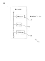
図1は、位置推定装置が実装される車両制御システムの概略構成図である。図2は、位置推定装置の一つの実施形態である電子制御装置のハードウェア構成図である。 FIG. 1 is a schematic configuration diagram of a vehicle control system in which a position estimation device is mounted. FIG. 2 is a hardware configuration diagram of an electronic control device, which is one embodiment of the position estimation device.
本実施形態では、車両10に搭載され、かつ、車両10を制御する車両制御システム1は、車両の前方の画像を取得するカメラ2と、測位情報受信機3とを有する。また、車両制御システム1は、所定の領域の広域地図情報を記憶しており、測位情報受信機3が出力する測位情報に基づいて、測位情報により表される現在位置を含む狭い領域の地図情報を出力する第1電子制御装置(ECU)4を有する。さらに、車両制御システム1は、位置推定装置の一例であり、第1ECU4が出力する地図情報を用いて車両10の位置を推定する第2電子制御装置(ECU)5を有する。
In the present embodiment, the
カメラ2は、領域データとして、車両10の前方の画像を撮影する。撮影された画像には、車両10の前方の所定の領域内に含まれる車線区画線などの地物が表わされる。カメラ2は、撮像部の一例であり、CCDあるいはC-MOSなど、可視光に感度を有する光電変換素子のアレイで構成された2次元検出器と、その2次元検出器上に撮影対象となる領域の像を結像する結像光学系を有する。そしてカメラ2は、車両10の前方を向くように、例えば、車両10の車室内に取り付けられる。そしてカメラ2は、所定の撮影周期ごとに車両10の前方領域を撮影し、その前方領域が写った画像を生成する。カメラ2は、画像を生成する度に、画像及び画像を取得した情報取得時刻を、車内ネットワーク6を介して第2ECU5へ出力する。カメラ2により生成された画像は、カラー画像であってもよく、又は、グレー画像であってもよい。
The
測位情報受信機3は、車両10の現在位置を表す測位情報を取得する。例えば、測位情報受信機3は、GPS受信機とすることができる。そして測位情報受信機3は、所定の受信周期で測位情報を取得する度に、測位情報及び測位情報を取得した時刻を、第1ECU4へ出力する。
The
第1ECU4は、磁気ディスクドライブ又は不揮発性の半導体メモリなどの記憶装置(図示せず)を有しており、この記憶装置は、車両10の現在位置を含む広い範囲(例えば数km四方の範囲)の広域地図情報を記憶する。この広域地図情報は、道路上の車線区画線などの地物、構造物の種類及び位置を表す情報を含む高精度地図情報であることが好ましい。なお、道路上の地物、構造物の位置は、例えば、実空間における所定の基準位置を原点とする世界座標系で表される。第1ECU4は、例えば、無線通信部(図示せず)を有しており、車両10の現在位置に応じて、無線通信部を用いて外部のサーバから広域地図情報を受信して記憶装置に記憶する。第1ECU4は、測位情報受信機3から入力した測位情報を入力する度に、記憶している広域地図情報を参照して、測位情報により表される現在位置を含む狭い領域(例えば、数十〜数百m四方の範囲)の地図情報及び測位情報取得した時刻を、車内ネットワーク6を介して第2ECU5へ出力する。第1ECU4は、地物が表された地図を記憶する記憶部の一例である。
The
第2ECU5は、車両10を制御する。本実施形態では、第2ECU5は、カメラ2が出力する画像に基づいて車両10の位置を推定して、車両10を自動運転するように車両10を制御する。そのために、第2ECU5は、通信インターフェース21と、メモリ22と、プロセッサ23とを有する。
The
通信インターフェース21は、通信部の一例であり、第2ECU5を車内ネットワーク6に接続するためのインターフェース回路を有する。すなわち、通信インターフェース21は、車内ネットワーク6を介して、カメラ2などと接続される。そして通信インターフェース21は、例えば、カメラ2から画像及び情報取得時刻を受信する度に、受信した画像及び情報取得時刻をプロセッサ23へわたす。また通信インターフェース21は、第1ECU4から測位情報、測位情報を取得した時刻及び地図情報を受信する度に、受信した測位情報、測位情報取得した時刻及び地図情報をプロセッサ23へわたす。また通信インターフェース21は、図示しない車両速度センサ及びヨーレートセンサから受信した車両速度及びヨーレートを、プロセッサ23へわたす。
The
メモリ22は、記憶部の一例であり、例えば、揮発性の半導体メモリ及び不揮発性の半導体メモリを有する。そしてメモリ22は、第2ECU5のプロセッサ23により実行される位置決定処理において使用される各種のデータ、例えば、カメラ2の光軸方向及び取り付け位置などの設置位置情報、結像光学系の焦点距離及び画角といった内部パラメータなどを記憶する。また、メモリ22は、カメラ2などから受信した画像、第1ECU4から受信した測位情報、測位情報を取得した時刻及び地図情報などを記憶する。
The
プロセッサ23は、制御部の一例であり、1個または複数個のCPU(Central Processing Unit)及びその周辺回路を有する。プロセッサ23は、論理演算ユニット、数値演算ユニットあるいはグラフィック処理ユニットといった他の演算回路をさらに有していてもよい。プロセッサ23が複数個のCPUを有する場合、CPUごとにメモリを有していてもよい。そして、プロセッサ23は、カメラ2により画像が生成される度に、この画像に対して設定された照合範囲内に含まれる候補点に基づいて、情報取得時刻における車両10の位置を推定する位置推定処理を実行する。また、プロセッサ23は、所定の周期で設定される位置決定時刻において、前回の位置決定時刻における車両10の位置と、情報取得時刻における車両10の位置と、車両速度及びヨーレートに基づいて、今回の位置決定時刻における車両10の位置を推定する。さらに、プロセッサ23は、推定された車両10の位置と、車両10の周囲の他の物体との相対的な位置関係に基づいて、車両10を自動運転するよう、車両10を制御する。
The
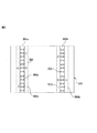
図3は、位置推定処理を含む車両制御処理に関する、第2ECU5のプロセッサ23の機能ブロック図である。プロセッサ23は、候補点検出部31と、候補点カウント部32と、照合範囲設定部33と、位置推定部34と、物体検出部35と、運転計画部36と、車両制御部37とを有する。プロセッサ23が有するこれらの各部は、例えば、プロセッサ23上で動作するコンピュータプログラムにより実現される機能モジュールである。あるいは、プロセッサ23が有するこれらの各部は、プロセッサ23に設けられる、専用の演算回路であってもよい。また、プロセッサ23が有するこれらの各部のうち、候補点検出部31と、候補点カウント部32と、照合範囲設定部33と、位置推定部34とが、位置推定処理を実行する。
FIG. 3 is a functional block diagram of the
次に、候補点検出部31と、候補点カウント部32と、照合範囲設定部33とが、協働して画像内の照合範囲を設定する処理を、図4〜図6を参照して、以下に説明する。この照合範囲を設定する処理は、カメラ2から画像が出力される度に行われることが好ましい。
Next, the process in which the candidate
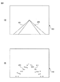
候補点検出部31は、カメラ2により生成された画像から、地物の一例である車線区画線を表す複数の候補点を検出する。図4(A)は、カメラ2により生成された画像400を示す図である。まず、候補点検出部31は、例えば、カメラ2により生成された画像に対してSobelフィルタといったエッジ検出フィルタを適用してエッジとなる画素を検出し、かつ、検出された画素の中で所定のしきい値以上の輝度を有する画素を候補点として検出する。また、候補点検出部31は、例えば、画像を識別器に入力することで画像内の候補点を検出してもよい。識別器として、例えば、入力された画像から、その画像内の車線区画線などの地物を検出するように予め学習されたディープニューラルネットワーク(DNN)を用いることができる。候補点検出部31は、画像内で地物として識別された領域内の画素を候補点として検出する。図4(B)は、画像410上に検出された候補点411を示す図である。候補点検出部31は、検出された画像内の候補点の位置情報を、候補点カウント部32へ通知する。候補点の位置情報は、例えば、画像400の左上の隅の位置を原点として、右方に伸びるxi軸と、下方に伸びるyi軸とを有する画像座標系で表すことができる。また、候補点検出部31は、候補点を検出するのに用いた画像及び画像が取得された情報取得時刻を、候補点カウント部32へ通知する。
The candidate
候補点カウント部32は、カメラ2により生成された画像に対して設定される第1照合範囲候補内の候補点の数をカウントする。また、候補点カウント部32は、第1照合範囲候補を含みかつ第1照合範囲候補よりも大きい、カメラ2により生成された画像に対して設定される第2照合範囲候補内の候補点の数をカウントする。
The candidate
まず、候補点カウント部32は、画像座標系で表された候補点の座標を、カメラ2の位置を原点とするカメラ座標系で表す。カメラ座標系では、撮像面の中心を原点として、車両10の進行方向をzc軸とし、zc軸と直交し、かつ、地面に平行な方向をxc軸とし、鉛直方向をyc軸とする。原点は、地面からカメラ2が設置される高さにある。カメラ2により撮影された地面上の車線区画線は、yc座標が一定である地面上に位置すると仮定される。候補点検出部31は、画像座標系で表された候補点の座標に対して、カメラ2の設置位置情報及び内部パラメータなどの情報を用いて視点変換処理を実行することで、候補点の座標をカメラ座標系で表わす。
First, the candidate
そして、候補点カウント部32は、カメラ座標系で表された候補点の座標を、世界座標系で表す。候補点カウント部32は、位置推定部34から通知された前回の位置決定時刻における車両10の位置と、前回の位置決定時刻と情報取得時刻との間の車両10の移動量及び移動方向とに基づいて、情報取得時刻における車両10の位置及び進行方向を推定する。ここで、候補点カウント部32は、前回の位置決定時刻と情報取得時刻との間の車両10の移動量及び移動方向を、その間に通知された車両速度及びヨーレートに基づいて算出する。候補点カウント部32は、カメラ2の設置位置情報及び内部パラメータなどの情報と、推定された車両10の位置及び進行方向とを用いて、情報取得時刻におけるカメラ2の仮定位置及び仮定姿勢を推定する。候補点カウント部32は、情報取得時刻におけるカメラ2の仮定位置及び仮定姿勢に従って、カメラ座標系から、世界座標系への変換式を求める。そのような変換式は、座標系間の回転を表す回転行列と座標系間の平行移動を表す並進ベクトルの組み合わせで表される。そして候補点カウント部32は、その変換式に従って、カメラ座標系で表された候補点の座標を、世界座標系の座標に変換する。
Then, the candidate
そして、候補点カウント部32は、候補点検出部31から通知された情報取得時刻に取得された画像に対する第1照合範囲候補を、カメラ2により生成された画像に対して設定する。第1照合範囲候補は、候補点をカウントするために使用される画像内の領域である。候補点カウント部32は、情報取得時刻におけるカメラ2の仮定位置及び仮定姿勢に従って、情報取得時刻にカメラ2により生成された画像に表されると仮定される領域を地図情報から切り出して、参照画像を生成する。候補点カウント部32は、カメラ2により生成された画像に対して、参照画像上の車線区画線と対応する領域を含むように第1照合範囲候補を設定する。ここでは、第1照合範囲候補を表す領域の座標は、世界座標系で表される。図5は、参照画像500を用いて、車両10の左右それぞれの車線区画線501a、501bについて第1照合範囲候補503a、503bを設定した図である。
Then, the candidate
また、候補点カウント部32は、第1照合範囲候補を含みかつ第1照合範囲候補よりも大きい第2照合範囲候補を、カメラ2により生成された画像に対して設定する。ここでは、第2照合範囲候補を表す領域の座標は、世界座標系で表される。候補点カウント部32は、例えば、第1照合範囲候補の輪郭から所定の画素数だけ拡大させて、第2照合範囲候補を設定してもよい。候補点カウント部32は、図5に示すように、第1照合範囲候補503a、503bのそれぞれについて、第1照合範囲候補503a、503bの輪郭を車線区画線501a、501bが伸びる方向と直交する横方向に拡大して、第2照合範囲候補504a、504bを設定してもよい。また、候補点カウント部32は、第2照合範囲候補504a、504bのそれぞれについて、車線区画線が伸びる方向に対して第1照合範囲候補の輪郭を左右対称に拡大して設定してもよいし、または、左右非対称に拡大して設定してもよい。車線区画線の片側が路肩と隣接している場合、車線区画線の車線側の輪郭は、路肩側の輪郭よりも摩耗して候補点として検出されにくくなっていることがある。そこで、候補点カウント部32は、第2照合範囲候補504a、504bのそれぞれについて、第1照合範囲候補の車線側の拡大量を路肩側よりも大きくなるように設定してもよい。これにより、車線区画線が候補点として検出されるやすくなる。また、候補点カウント部32は、第2照合範囲候補504a、504bのそれぞれについて、第1照合範囲候補の路肩側の拡大量がゼロとなるように設定してもよい。これにより、路肩を候補点として検出することが防止される。
Further, the candidate
なお、候補点カウント部32は、世界座標系で表された地図情報に基づいて、カメラ2により撮影された仮想画像を作成し、仮想画像上の車線区画線と対応する領域を含むように第1照合範囲候補をカメラ2により生成された画像に対して設定してもよい。例えば、候補点カウント部32は、画像が取得された情報取得時刻におけるカメラ2の位置を仮想撮影点とし、かつ、カメラ2の光軸方向を撮影方向として、仮想撮影点から設定された撮影方向に向けて地図情報に含まれる道路上の車線区画線を仮想的に撮影した仮想画像を生成する。仮想画像は、例えば、カメラ2により生成される画像と同サイズとすることが好ましい。候補点カウント部32は、カメラ2により生成された画像を仮想画像上に重畳して、第1照合範囲候補を、仮想画像上の車線区画線と対応する領域を含むようにカメラ2により生成される画像に対して設定することができる。
The candidate
そして、候補点カウント部32は、カメラ2により生成された画像に対して設定された第1照合範囲候補内の候補点の数をカウントする。例えば、候補点カウント部32は、図5に示す参照画像500において、第1照合範囲候補503a、503bの内側に位置する候補点502の数Aをカウントする。候補点カウント部32は、候補点の数Aと、候補点の位置情報と、第1照合範囲候補を表す情報と、第1照合範囲候補が設定された画像及び情報取得時刻とを、照合範囲設定部33へ通知する。
Then, the candidate
また、候補点カウント部32は、カメラ2により生成された画像に対して設定された第2照合範囲候補内の候補点の数Bをカウントする。候補点カウント部32は、図5に示す画像500において、第2照合範囲候補504a、504bの内側に位置する候補点502の数Bをカウントする。候補点カウント部32は、候補点の数Bと、候補点の位置情報と、第2照合範囲候補を表す情報と、第2照合範囲候補が設定された画像及び情報取得時刻とを、照合範囲設定部33へ通知する。
Further, the candidate
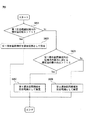
照合範囲設定部33は、第1照合範囲候補内の候補点の数又は第2照合範囲候補内の候補点の数のうちの少なくとも1つに基づいて、地図上の対応する車線区画線の位置と照合する照合範囲を画像に対して設定する。図6は、照合範囲設定部の動作を説明するフローチャートである。照合範囲設定部33は、まず、第1照合範囲候補内の候補点の数が、第1のしきい値Th1よりも大きいか否かを判定する(図6のステップS601)。第1のしきい値Th1は、例えば、第1照合範囲候補の領域に含まれる画素数に基づいて決定される。具体的には、照合範囲設定部33は、第1照合範囲候補の領域に含まれる画素数と、所定の係数(0<係数=<1)との積を、第1のしきい値Th1として求めてもよい。
The collation
第1照合範囲候補内の候補点の数が、第1のしきい値Th1よりも大きい場合(ステップS601−Yes)、照合範囲設定部33は、第1照合範囲候補を照合範囲として決定する(ステップS603)。照合範囲設定部33は、決定された照合範囲を表す情報と、候補点の位置情報と、照合範囲が設定された画像及び情報取得時刻とを、位置推定部34へ通知する。これにより、照合範囲設定部33は、比較的狭い照合範囲内で十分な数の候補点が得られる場合には、過剰に照合範囲を広げることが抑制されるので、適切でない地物を候補点として照合に用いられないように照合範囲を設定できる。例えば、照合範囲設定部33は、明瞭な車線区画線を撮影できる場合には、照合範囲を比較的狭くすることができる。なお、候補点カウント部32は、第1照合範囲候補内の候補点の数をカウントした時点で、カウントした候補点の数を照合範囲設定部33へ通知し、照合範囲設定部33がステップS601の判定を行うようにしてもよい。この場合、第1照合範囲候補内の候補点の数が、第1のしきい値Th1よりも大きい場合には、候補点カウント部32が、第2照合範囲候補を設定すること及び第2照合範囲候補内の候補点の数をカウントする処理を省略するようにしてもよい。一方、候補点カウント部32は、第1照合範囲候補内の候補点の数が、第1のしきい値Th1以下の場合には、第2照合範囲候補を設定すること及び第2照合範囲候補内の候補点の数をカウントする処理を実行する。
When the number of candidate points in the first collation range candidate is larger than the first threshold value Th1 (step S601-Yes), the collation
一方、第1照合範囲候補内の候補点の数が、第1のしきい値Th1以下の場合(ステップS601−No)、照合範囲設定部33は、第2照合範囲候補内の候補点の数Bに対する第1照合範囲候補内の候補点の数Aの比(A/B)が第2のしきい値よりも大きいか否かを判定する(ステップS605)。第2のしきい値は、例えば、第1照合範囲候補の領域に含まれる画素数と、第2照合範囲候補の領域に含まれる画素数とに基づいて決定される。具体的には、照合範囲設定部33は、第1照合範囲候補の領域に含まれる画素数に対する第2照合範囲候補の領域に含まれる画素数の比と、所定の係数(0<係数=<1)との積を、第2のしきい値として求めてもよい。
On the other hand, when the number of candidate points in the first collation range candidate is equal to or less than the first threshold value Th1 (step S601-No), the collation
第2照合範囲候補内の候補点の数Bに対する第1照合範囲候補内の候補点の数Aの比(A/B)が第2のしきい値よりも大きい場合(ステップS605−Yes)、照合範囲設定部33は、第1照合範囲候補を照合範囲として決定する(ステップS607)。照合範囲設定部33は、決定された照合範囲を表す情報と、候補点の位置情報と、照合範囲が設定された画像及び情報取得時刻とを、位置推定部34へ通知する。例えば、車線区画線等の地物の状態によっては、そもそも適切な地物から得られる候補点の絶対数が少ないことがある。そのような場合でも、照合範囲設定部33は、第2照合範囲候補内の候補点の数Bに対する第1照合範囲候補内の候補点の数Aの比(A/B)が大きければ、照合範囲を比較的狭い範囲に設定することにより、過剰に照合範囲を広げることが抑制されるので、適切でない地物を候補点として照合に用いられないように照合範囲を設定できる。例えば、車線区画線が摩耗などにより劣化してかすれている場合でも、照合範囲設定部33は、照合範囲を過剰に広げない。
When the ratio (A / B) of the number of candidate points A in the first collation range candidate to the number B of candidate points in the second collation range candidate is larger than the second threshold value (step S605-Yes). The collation
一方、第2照合範囲候補内の候補点の数Bに対する第1照合範囲候補内の候補点の数Aの比(A/B)が第2のしきい値以下の場合(ステップS605−No)、照合範囲設定部33は、第2照合範囲候補を照合範囲として決定する(ステップS609)。照合範囲設定部33は、決定された照合範囲を表す情報と、候補点の位置情報と、照合範囲が設定された画像及び情報取得時刻とを、位置推定部34へ通知する。これにより、車両10の推定位置がずれて第1照合範囲内に検出される候補点の数が少ない場合には、照合範囲設定部33は、照合範囲を広げることにより、十分な数の候補点を検出することができる。
On the other hand, when the ratio (A / B) of the number of candidate points A in the first collation range candidate to the number B of candidate points in the second collation range candidate is equal to or less than the second threshold value (step S605-No). , The collation
以上が、照合範囲を設定する処理の説明である。 The above is the description of the process of setting the collation range.
位置推定部34は、複数の候補点の中から照合範囲内に検出された候補点と、地図上の対応する車線区画線とを照合することで、車両10の位置を推定する。位置推定部34は、照合範囲設定部33から画像及びこの画像に対する照合範囲が通知される度に、画像及び照合範囲を用いて、情報取得時刻における車両10の位置を推定する。位置推定部34は、情報取得時刻におけるカメラ2の仮定位置及び仮定姿勢に従って、照合範囲内に含まれる候補点の座標を、地図情報により表される地図上に投影して、地図情報に表された車両10の周囲の車線区画線と照合範囲内に含まれる候補点との一致度合を算出する。位置推定部34は、仮定位置及び仮定姿勢を所定量ずつ変化させながら、上記と同様のカメラ座標系から世界座標系への位置変換及び一致度合の算出の各処理を実行することで、複数の仮定位置及び仮定姿勢のそれぞれについて、地図情報に表された車両10の周囲の車線区画線と照合範囲内に含まれる候補点との一致度合を算出する。位置推定部34は、一致度合が最大となるときの仮定位置及び仮定姿勢を特定し、そのカメラ2の仮定位置及び仮定姿勢に基づいて、カメラ2が画像を撮影した情報取得時刻における車両10の位置及び進行方向を推定する。第1ECU4は、画像を取得した情報取得時刻と、地図情報を生成するのに使用される測位情報が取得された時刻との間に車両10が走行し得る領域を含むように地図情報を出力することが好ましい。これにより、位置推定部34は、最新の地図情報を用いて、車両10の位置及び進行方向を算出できる。
The
位置推定部34は、所定の周期で設定される位置決定時刻において、位置決定時刻における車両10の位置を、情報取得時刻における車両10の位置と、位置決定時刻と情報取得時刻との間の車両10の移動量及び移動方向とに基づいて推定する。位置推定部34は、位置決定時刻と情報取得時刻との間の車両10の移動量及び移動方向を、その間に入力した車両速度及びヨーレートに基づいて算出する。
The
位置決定時刻の周期が、情報取得時刻の更新される間隔と一致しない場合(例えば、位置決定時刻の周期が情報取得時刻の更新される間隔よりも短い場合)、位置推定部34は、前回の位置決定時刻に推定された車両10の位置と、前回の位置決定時刻と今回の位置決定時刻との間の車両10の移動量及び移動方向とに基づいて、今回の位置決定時刻における車両10の位置を推定する。位置推定部34は、前回の位置決定時刻と今回の位置決定時刻との間の車両10の移動量及び移動方向を、その間に入力した車両速度及びヨーレートに基づいて算出する。
When the cycle of the position-fixing time does not match the update interval of the information acquisition time (for example, when the cycle of the position-fixing time is shorter than the update interval of the information acquisition time), the
物体検出部35は、カメラ2により生成された画像を取得し、この画像に基づいて、車両10の周囲の他の物体を検出する。物体検出部35は、例えば、画像を識別器に入力することで画像に表された物体を検出する。識別器として、例えば、入力された画像から、その画像に表された物体を検出するように予め学習されたディープニューラルネットワーク(DNN)を用いることができる。物体検出部35は、DNN以外の識別器を用いてもよい。例えば、物体検出部35は、識別器として、画像上に設定されるウィンドウから算出される特徴量(例えば、Histograms of Oriented Gradients, HOG)を入力として、そのウィンドウに検出対象となる物体が表される確信度を出力するように予め学習されたサポートベクトルマシン(SVM)を用いてもよい。あるいはまた、物体検出部35は、検出対象となる物体が表されたテンプレートと画像との間でテンプレートマッチングを行うことで、物体領域を検出してもよい。また、物体検出部35は、オプティカルフローに基づく追跡処理に従って、最新の画像から検出された物体を過去の画像から検出された物体と対応付けることで、最新の画像から検出された物体を追跡してもよい。そして物体検出部35は、時間経過に伴う画像上での追跡中の物体のサイズの変化に基づいて、車両10に対するその物体の相対速度を推定してもよい。そして、物体検出部35は、各画像に基づいて検出された物体について同一物を判定し、同一と判定された物体は1つの物体として判断する。物体検出部35は、検出された物体の位置を示す情報を、運転計画部36へ通知する。なお、物体検出部35は、ライダセンサ等の距離画像を取得するセンサが測定した測定結果に基づいて、車両10の周囲の他の物体を検出してもよい。
The
運転計画部36は、位置決定時刻における車両10の位置と、検出された物体の位置を示す情報と、地図情報とを取得する。運転計画部36は、これらの情報に基づいて、車両10の走行予定経路を1以上生成する。走行予定経路は、例えば、現時刻から所定時間先までの各時刻における、車両10の目標位置の集合として表される。運転計画部36は、車両10の位置と、地図に表された道路上の構造物と、検出された他の物体との位置関係に応じて、車両10と他の物体との相対的な位置関係を推定する。例えば、運転計画部36は、地図に表された車線と、他の物体との位置関係に応じて、他の物体が走行している車線を特定することで、他の物体と車両10とが同じ車線を走行しているか否かを判定する。例えば、運転計画部36は、他の物体の水平方向の中心位置を挟むように位置する互いに隣接する二つの車線区画線で特定される車線を他の物体が走行していると判定する。同様に、運転計画部36は、車両10を挟むように位置する互いに隣接する二つの車線区画線で特定される車線を車両10が走行していると判定する。そして運転計画部36は、車両10が走行中の車線と他の物体が走行中の車線とが同一か否かを判定する。また、地図に表された隣接する二つの車線区画線間の間隔は既知であり、かつ、カメラの焦点距離といった内部パラメータが既知であるため、画像上での隣接する二つの車線区画線間の間隔により、車両10からの距離が推定できる。そこで、運転計画部36は、画像上での他の物体の位置における、地図に表された隣接する二つの車線区画線間の間隔に基づいて、車両10から他の物体までの距離を推定してもよい。このように、運転計画部36は、地図に表された道路上の構造物との位置関係で他の物体と車両10との相対的な位置関係を推定する。そのため、運転計画部36は、画像に写った車線区画線などの道路上の地物が不明瞭でも、他の物体と車両10との相対的な位置関係を正確に推定できる。
The driving
運転計画部36は、検出された他の物体が走行中の車線及び相対距離に基づいて、他の物体と車両10とが異なる車線を走行するか、あるいは、車両10から他の物体までの相対距離が所定距離以上となるように、車両10の走行予定経路を生成する。なお、運転計画部36は、複数の走行予定経路を生成してもよい。この場合、運転計画部36は、複数の走行予定経路のうち、車両10の加速度の絶対値の総和が最小となる経路を選択してもよい。運転計画部36は、生成した走行予定経路を車両制御部37へ通知する。
The driving
車両制御部37は、位置決定時刻における車両10の位置と、車両速度及びヨーレートと、通知された走行予定経路とに基づいて、車両10が通知された走行予定経路に沿って走行するように車両10の各部を制御する。例えば、車両制御部37は、通知された走行予定経路、及び、車両10の現在の車両速度及びヨーレートに従って、車両10の操舵角、加速度及び角加速度を求め、その操舵角、加速度及び角加速度となるように、操舵量、アクセル開度またはブレーキ量を設定する。そして車両制御部37は、設定された操舵量に応じた制御信号を、車両10の操舵輪を制御するアクチュエータ(図示せず)へ出力する。また、車両制御部37は、設定されたアクセル開度に従って燃料噴射量を求め、その燃料噴射量に応じた制御信号を車両10のエンジンの燃料噴射装置(図示せず)へ出力する。あるいは、車両制御部37は、設定されたブレーキ量に応じた制御信号を車両10のブレーキ(図示せず)へ出力する。
The
以上に説明してきたように、この位置推定装置は、移動物体の周囲の所定の領域内の地物を表す領域データから、地物を表す候補点を検出する。位置推定装置は、領域データにより表されるデータ領域内に設定される第1照合範囲候補内の候補点の数をカウントし、かつ、第1照合範囲候補を含みかつ第1照合範囲候補よりも大きい、データ領域内に設定される第2照合範囲候補内の前記候補点の数をカウントする。位置推定装置は、第1照合範囲候補内の候補点の数又は第2照合範囲候補内の候補点の数のうちの少なくとも1つに基づいて、地図上の対応する地物の位置と照合する照合範囲をデータ領域に対して設定する。そして、位置推定装置は、照合範囲内に含まれる候補点に基づいて、移動物体の位置を推定する。これにより、適切な地物を表す候補点を含むように照合範囲を設定できるので、検出された候補点に基づいて、移動物体の正しい位置を推定できる。 As described above, this position estimation device detects a candidate point representing a feature from the area data representing the feature in a predetermined area around the moving object. The position estimation device counts the number of candidate points in the first collation range candidate set in the data area represented by the area data, includes the first collation range candidate, and is more than the first collation range candidate. The number of the candidate points in the large second collation range candidate set in the data area is counted. The position estimation device collates with the position of the corresponding feature on the map based on at least one of the number of candidate points in the first collation range candidate or the number of candidate points in the second collation range candidate. Set the collation range for the data area. Then, the position estimation device estimates the position of the moving object based on the candidate points included in the collation range. As a result, the collation range can be set so as to include candidate points representing appropriate features, so that the correct position of the moving object can be estimated based on the detected candidate points.
次に、第1照合範囲候補を設定する他の例を、図7〜図10を参照しながら、以下に説明する。 Next, another example of setting the first collation range candidate will be described below with reference to FIGS. 7 to 10.
上述したように第1照合範囲候補は、カメラ2により画像が撮影された時の車両10の推定される位置及び姿勢に基づいて設定される。車両10の推定される位置が正しい場合には、第1照合範囲候補は、地図情報に含まれる車線区画線などの地物と対応するように設定されるので、第1照合範囲候補内には、十分な数の候補点を検出することができる。図7(A)は、前方のカーブしている道路を撮影した画像内に設定された照合範囲内に十分な数の候補点を検出できた例を示す図である。車両700の前方に位置する車線区画線701を含むように第1照合範囲候補702が設定されており、第1照合範囲候補702内には、多くの数の候補点703が検出されている。
As described above, the first collation range candidate is set based on the estimated position and posture of the
一方、車両10の推定される位置には誤差が生じる場合がある。例えば、車両10の進行方向の推定される位置が正しい位置に対してずれていると、前方のカーブしている道路の車線区画線を検出する場合、第1照合範囲候補が車線区画線からずれてしまうおそれがある。図7(B)は、前方のカーブしている道路を撮影した画像に設定された照合範囲内に含まれる候補点が少ない例を示す図である。車両700の進行方向の推定される位置が正しい位置に対してずれているので、第1照合範囲候補702内に検出される候補点703の数が減少する。
On the other hand, an error may occur in the estimated position of the
そこで、候補点カウント部32は、カメラ2により生成された画像内に検出された複数の候補点により形成される曲線から、画像内の車線区画線の曲率を推定し、この曲率が大きい程、第1照合範囲候補の幅が広がるように第1照合範囲候補を設定してもよい。
Therefore, the candidate
候補点カウント部32は、世界座標系で表された複数の候補点の座標(xw、zw)をクロソイドの近似式:xw=P1+P2×zw+(P3/2)×zw2+(P4/6)×zw3に入力する。ここで、P1は、zw=0における車線区画線のxw座標、P2は、zw=0における車線区画線の方位角、P3は、zw=0における車線区画線の曲率、P4は、曲率変化率(クロソイド曲線では一定)である。なお、地面に対して鉛直方向の候補点の座標ywは、一定であると仮定している。
The candidate
候補点カウント部32は、クロソイドの近似式に対して、最小二乗法等の多変量解析を適用して、P1、P2、P3、P4を求める。これにより、照合範囲設定部33は、車線区画線の曲率P4を得る。
The candidate
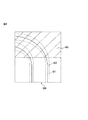
候補点カウント部32は、カメラ2により生成された画像に対して、車線区画線の曲率が大きい程、第1照合範囲候補における車両10の進行方向と直交する方向である横方向の幅が広がるように第1照合範囲候補を設定する。候補点カウント部32は、第1照合範囲候補を含みかつ第1照合範囲候補よりも大きくなるように、第2照合範囲候補を設定する。照合範囲設定部33は、このように設定された第1照合範囲候補または第2照合範囲候補のうちの少なくとも1つに基づいて、照合範囲を設定する。図8は、車線区画線の曲率に応じて、車両の進行方向と直交する横方向の照合範囲を変化させることを説明する図である。図8に示すように、車両10の前方の道路がカーブしており、車線区画線801も同様にカーブしている場合、照合範囲802の横方向の幅は、車両10からの距離が離れる程大きく設定される。このように、候補点カウント部32は、車線区画線の曲率が大きい程、照合範囲を拡大することで、十分な数の候補点を検出することができる。ここで、候補点カウント部32は、車線区画線の曲率が所定のしきい値以下の場合、車線区画線は直線であると判定して、第1照合範囲候補の横方向の幅を一定としてもよい。
The width of the candidate
また、候補点カウント部32は、カメラ2により画像が撮影された情報取得時刻における車両10の位置及び進行方向と、地図情報が含む車線区画線の位置情報とに基づいて、走行している車線の曲率として車線区画線の曲率を求め、この曲率が大きい程、第1照合範囲候補の横方向の幅が広がるように第1照合範囲候補を設定してもよい。情報取得時刻における車両10の進行方向を、位置決定時刻における位置の経時変化、又は、情報取得時刻におけるヨーレートに基づいて決定してもよい。
Further, the candidate
更に、候補点カウント部32は、第3のしきい値以上の曲率の車線区画線を含む画像内の領域を、照合範囲から除外してもよい。候補点カウント部32は、この第3のしきい値を、例えば、以下のようにして求めることができる。まず、測位情報に基づいて決定される車両10の進行方向のずれΔzは既知であるとする。また、候補点カウント部32は、地図情報に含まれる車線区画線と車線区画線と隣接する路肩の位置情報に基づいて、車線区画線と隣接する路肩との距離Δxを求める。候補点カウント部32は、地図情報が含む車線区画線の位置を、進行方向にΔzずらして、車線区画線が隣接する路肩と重なる位置における車線区画線の曲率を求めて、この車線区画線の曲率を第3のしきい値とする。
Further, the candidate
図9は、カメラ2により生成された画像900内に検出された候補点の一部を照合範囲から除外することを説明する図である。画像900は、車線区画線901と、照合範囲902とを含む。候補点カウント部32は、第3のしきい値以上の曲率の車線区画線を含む画像内の領域1003を、画像内の照合範囲から除外する。これにより、候補点カウント部32は、路肩等の地物を照合範囲から除外して、候補点として照合されることを防ぐ。
FIG. 9 is a diagram for explaining that a part of the candidate points detected in the
また、プロセッサ23は、カメラ2により生成された画像を、車両10の進行方向又は横方向に沿って複数の領域に分割する領域分割部38を有していてもよい(図3参照)。領域分割部38は、画像を、複数の領域に分割して、複数の領域を表す情報を、候補点検出部31へ通知する。図10は、カメラ2により生成された画像1000を車両10の進行方向において3つの領域1000a、1000b、1000cに分割して、分割された領域ごとに照合範囲を設定することを説明する図である。候補点カウント部32は、複数の領域1000a、1000b、1000cごとに設定される第1照合範囲候補内の候補点の数をカウントし、かつ、複数の領域1000a、1000b、1000cごとに設定される第2照合範囲候補内の数を前記候補点の数をカウントする。照合範囲設定部33は、複数の領域1000a、1000b、1000cごとに、第1照合範囲候補内の候補点の数又は第2照合範囲候補内の候補点の数のうちの少なくとも1つに基づいて、照合範囲1001,1002,1003を設定する。
Further, the
本発明では、上述した実施形態の位置推定装置、本発明の趣旨を逸脱しない限り適宜変更が可能である。 In the present invention, the position estimation device of the above-described embodiment can be appropriately modified as long as the gist of the present invention is not deviated.
例えば、上述した実施形態では、領域データは、カメラが撮影した画像であり、2次元の情報を有していた。この領域データは、レーザ又はミリ波等の電磁波を照射して地物から反射された反射波に基づいて求められた地物を表す距離画像であってもよい。この場合、領域データは、三次元の情報を有する。 For example, in the above-described embodiment, the area data is an image taken by a camera and has two-dimensional information. This region data may be a distance image representing a feature obtained based on a reflected wave reflected from the feature by irradiating an electromagnetic wave such as a laser or millimeter wave. In this case, the area data has three-dimensional information.
また、上述した実施形態では、画像内に検出される候補点は、車線区画線であったが、画像内に検出される候補点は、路肩、壁又はガードレールであってもよい。例えば、候補点として、路肩が検出される場合、照合範囲は、路肩と隣接するガードレールが候補点として照合されないように設定されることが好ましい。 Further, in the above-described embodiment, the candidate point detected in the image is the lane marking line, but the candidate point detected in the image may be a road shoulder, a wall, or a guardrail. For example, when a road shoulder is detected as a candidate point, the collation range is preferably set so that the guardrail adjacent to the road shoulder is not collated as a candidate point.
また、上述した実施形態において、第2照合範囲候補を含みかつ第2照合範囲候補よりも大きい、領域データ内に設定される第3照合範囲候補内の候補点の数をカウントして、第1照合範囲候補内の候補点の数又は第2照合範囲候補内の候補点の数又は第3照合範囲候補内の候補点の数のうちの少なくとも1つに基づいて、地図上の対応する地物の位置と照合する照合範囲を領域データに対して設定してもよい。 Further, in the above-described embodiment, the number of candidate points in the third collation range candidate set in the area data, which includes the second collation range candidate and is larger than the second collation range candidate, is counted and the first collation range candidate is counted. Corresponding features on the map based on at least one of the number of candidate points in the collation range candidate, the number of candidate points in the second collation range candidate, or the number of candidate points in the third collation range candidate. A collation range for collating with the position of may be set for the area data.
また、上述した実施形態において、領域データ(画像)内に左側の車線区画線を含むように照合範囲を設定し、かつ、領域データ内に右側の車線区画線を含むように照合範囲を設定してもよい。これにより、領域データ内の左右それぞれの照合範囲内の候補点を独立して検出することができる。 Further, in the above-described embodiment, the collation range is set so as to include the left lane division line in the area data (image), and the collation range is set so as to include the right lane division line in the area data. You may. As a result, the candidate points in the left and right collation ranges in the area data can be independently detected.
1 車両制御システム
2 カメラ
3 測位情報受信機
4 第1電子制御装置
5 第2電子制御装置
6 車内ネットワーク
10 車両
21 通信インターフェース
22 メモリ
23 プロセッサ
31 候補点検出部
32 候補点カウント部
33 照合範囲設定部
34 位置推定部
35 物体検出部
36 運転計画部
37 車両制御部
1
Claims (8)
移動物体に取り付けられたセンサを用いて取得された当該移動物体の周囲の所定の領域内の地物を表す領域データから、前記地物を表す複数の候補点を検出する検出部と、
前記複数の候補点の中から、前記領域データに対して設定される第1照合範囲候補内の前記候補点の数をカウントし、かつ、前記複数の候補点の中から、前記第1照合範囲候補を含みかつ前記第1照合範囲候補よりも大きい、前記データ領域に対して設定される第2照合範囲候補内の前記候補点の数をカウントする候補点カウント部と、
前記第1照合範囲候補内の前記候補点の数又は前記第2照合範囲候補内の前記候補点の数のうちの少なくとも1つに基づいて、前記地図上の対応する前記地物の位置と照合する照合範囲を前記データ領域に対して設定する照合範囲設定部と、
前記複数の候補点の中から前記照合範囲内に含まれる前記候補点と、前記地図上の対応する前記地物とを照合することで、前記移動物体の位置を推定する位置推定部と、
を有する位置推定装置。 A memory unit that stores a map showing features and
A detection unit that detects a plurality of candidate points representing the feature from the area data representing the feature in a predetermined area around the moving object acquired by using a sensor attached to the moving object.
From the plurality of candidate points, the number of the candidate points in the first collation range candidate set for the area data is counted, and from the plurality of candidate points, the first collation range. A candidate point counting unit that includes candidates and is larger than the first collation range candidate and counts the number of the candidate points in the second collation range candidate set for the data area.
Collation with the position of the corresponding feature on the map based on at least one of the number of candidate points in the first collation range candidate or the number of candidate points in the second collation range candidate. A collation range setting unit that sets the collation range to be performed for the data area,
A position estimation unit that estimates the position of the moving object by collating the candidate point included in the collation range from the plurality of candidate points with the corresponding feature on the map.
A position estimator having.
前記第1照合範囲候補内の前記候補点の数が、第1のしきい値よりも大きいか、又は、前記第1照合範囲候補内の前記候補点の数が前記第1のしきい値以下であり、かつ、前記第2照合範囲候補内の前記候補点の数に対する前記第1照合範囲候補内の前記候補点の数の比が第2のしきい値よりも大きい場合、前記第1照合範囲候補を前記照合範囲として決定し、
前記第1照合範囲候補内の前記候補点の数が、前記第1のしきい値以下であり、かつ、前記第2照合範囲候補内の前記候補点の数に対する前記第1照合範囲候補内の前記候補点の数の比が前記第2のしきい値以下の場合、前記第2照合範囲候補を前記照合範囲として決定する請求項1に記載の位置推定装置。 The collation range setting unit is
The number of the candidate points in the first collation range candidate is larger than the first threshold value, or the number of the candidate points in the first collation range candidate is equal to or less than the first threshold value. When the ratio of the number of the candidate points in the first collation range candidate to the number of the candidate points in the second collation range candidate is larger than the second threshold value, the first collation The range candidate is determined as the collation range, and
The number of the candidate points in the first collation range candidate is equal to or less than the first threshold value, and the number of the candidate points in the second collation range candidate is in the first collation range candidate. The position estimation device according to claim 1, wherein when the ratio of the number of candidate points is equal to or less than the second threshold value, the second collation range candidate is determined as the collation range.
前記照合範囲設定部は、
前記データ領域内に検出された複数の前記候補点により形成される曲線から、前記データ領域内の車線区画線の曲率を推定し、
前記曲率が大きい程、前記照合範囲の幅が広がるように当該照合範囲を設定する請求項1〜3の何れか一項に記載の位置推定装置。 The feature is a lane marking line
The collation range setting unit is
The curvature of the lane marking line in the data area is estimated from the curve formed by the plurality of candidate points detected in the data area.
The position estimation device according to any one of claims 1 to 3, wherein the collation range is set so that the width of the collation range becomes wider as the curvature is larger.
前記地図は車線区画線の位置を表し、
前記照合範囲設定部は、
前記位置推定部により推定された前記移動物体の現在位置及び進行方向と、前記地図に表わされる車線区画線の位置とに基づいて、前記データ領域内の車線区画線の曲率を求め、
前記曲率が大きい程、前記照合範囲の幅が広がるように当該照合範囲を設定する請求項1〜3の何れか一項に記載の位置推定装置。 The feature is a lane marking line
The map shows the location of the lane markings
The collation range setting unit is
Based on the current position and traveling direction of the moving object estimated by the position estimation unit and the position of the lane marking line represented on the map, the curvature of the lane marking line in the data area is obtained.
The position estimation device according to any one of claims 1 to 3, wherein the collation range is set so that the width of the collation range becomes wider as the curvature is larger.
前記検出部は、前記複数の候補点の中から、前記複数の領域ごとに前記候補点を検出し、
前記候補点カウント部は、前記複数の領域ごとに設定される前記第1照合範囲候補内の前記候補点の数をカウントし、かつ、前記複数の領域ごとに設定される前記第2照合範囲候補内の数を前記候補点の数をカウントし、
前記照合範囲設定部は、前記複数の領域ごとに、前記第1照合範囲候補内の前記候補点の数又は前記第2照合範囲候補内の前記候補点の数のうちの少なくとも1つに基づいて、前記照合範囲を設定する請求項1又は2に記載の位置推定装置。 It has a region dividing portion that divides the region data into a plurality of regions along the traveling direction of the moving object.
The detection unit detects the candidate points for each of the plurality of candidate points from the plurality of candidate points.
The candidate point counting unit counts the number of the candidate points in the first collation range candidate set for each of the plurality of regions, and the second collation range candidate set for each of the plurality of regions. Count the number of the candidate points,
The collation range setting unit is based on at least one of the number of the candidate points in the first collation range candidate or the number of candidate points in the second collation range candidate for each of the plurality of regions. The position estimation device according to claim 1 or 2, wherein the collation range is set.
前記複数の候補点の中から、前記領域データに対して設定される第1照合範囲候補内の前記候補点の数をカウントし、かつ、前記複数の候補点の中から、前記第1照合範囲候補を含みかつ前記第1照合範囲候補よりも大きい、前記データ領域に対して設定される第2照合範囲候補内の前記候補点の数をカウントすることと、
前記第1照合範囲候補内の前記候補点の数又は前記第2照合範囲候補内の前記候補点の数のうちの少なくとも1つに基づいて、前記地物が表された地図上の対応する前記地物の位置と照合する照合範囲を前記データ領域に対して設定することと、
前記複数の候補点の中から前記照合範囲内に含まれる前記候補点と、前記地図上の対応する前記地物とを照合することで、前記移動物体の位置を推定すること、
を、プロセッサに実行させるコンピュータプログラム。 From the area data representing a feature in a predetermined area around the moving object acquired by using a sensor attached to the moving object, a plurality of candidate points representing the feature can be detected.
From the plurality of candidate points, the number of the candidate points in the first collation range candidate set for the area data is counted, and from the plurality of candidate points, the first collation range. Counting the number of the candidate points in the second collation range candidate set for the data area, which includes the candidates and is larger than the first collation range candidate.
Corresponding said features on a map representing the feature based on at least one of the number of candidate points in the first collation range candidate or the number of candidate points in the second collation range candidate. Setting a collation range to match the position of the feature with respect to the data area
To estimate the position of the moving object by collating the candidate point included in the collation range with the corresponding feature on the map from the plurality of candidate points.
A computer program that causes the processor to execute.
Priority Applications (1)
| Application Number | Priority Date | Filing Date | Title |
|---|---|---|---|
| JP2019110253A JP7334489B2 (en) | 2019-06-13 | 2019-06-13 | Position estimation device and computer program |
Applications Claiming Priority (1)
| Application Number | Priority Date | Filing Date | Title |
|---|---|---|---|
| JP2019110253A JP7334489B2 (en) | 2019-06-13 | 2019-06-13 | Position estimation device and computer program |
Publications (2)
| Publication Number | Publication Date |
|---|---|
| JP2020201210A true JP2020201210A (en) | 2020-12-17 |
| JP7334489B2 JP7334489B2 (en) | 2023-08-29 |
Family
ID=73743334
Family Applications (1)
| Application Number | Title | Priority Date | Filing Date |
|---|---|---|---|
| JP2019110253A Active JP7334489B2 (en) | 2019-06-13 | 2019-06-13 | Position estimation device and computer program |
Country Status (1)
| Country | Link |
|---|---|
| JP (1) | JP7334489B2 (en) |
Citations (6)
| Publication number | Priority date | Publication date | Assignee | Title |
|---|---|---|---|---|
| JPH0935198A (en) * | 1995-07-14 | 1997-02-07 | Mitsubishi Electric Corp | Traveling road detector for vehicle |
| JP2009288867A (en) * | 2008-05-27 | 2009-12-10 | Toyota Motor Corp | Lane marking detection device and lane marking detection method |
| WO2017056249A1 (en) * | 2015-09-30 | 2017-04-06 | 日産自動車株式会社 | Travel control method and travel control device |
| WO2018212280A1 (en) * | 2017-05-19 | 2018-11-22 | パイオニア株式会社 | Measurement device, measurement method and program |
| WO2018212283A1 (en) * | 2017-05-19 | 2018-11-22 | パイオニア株式会社 | Measurement device, measurement method and program |
| JP2018200501A (en) * | 2017-05-25 | 2018-12-20 | 日産自動車株式会社 | Lane information output method and lane information output device |
-
2019
- 2019-06-13 JP JP2019110253A patent/JP7334489B2/en active Active
Patent Citations (6)
| Publication number | Priority date | Publication date | Assignee | Title |
|---|---|---|---|---|
| JPH0935198A (en) * | 1995-07-14 | 1997-02-07 | Mitsubishi Electric Corp | Traveling road detector for vehicle |
| JP2009288867A (en) * | 2008-05-27 | 2009-12-10 | Toyota Motor Corp | Lane marking detection device and lane marking detection method |
| WO2017056249A1 (en) * | 2015-09-30 | 2017-04-06 | 日産自動車株式会社 | Travel control method and travel control device |
| WO2018212280A1 (en) * | 2017-05-19 | 2018-11-22 | パイオニア株式会社 | Measurement device, measurement method and program |
| WO2018212283A1 (en) * | 2017-05-19 | 2018-11-22 | パイオニア株式会社 | Measurement device, measurement method and program |
| JP2018200501A (en) * | 2017-05-25 | 2018-12-20 | 日産自動車株式会社 | Lane information output method and lane information output device |
Also Published As
| Publication number | Publication date |
|---|---|
| JP7334489B2 (en) | 2023-08-29 |
Similar Documents
| Publication | Publication Date | Title |
|---|---|---|
| US11530924B2 (en) | Apparatus and method for updating high definition map for autonomous driving | |
| KR102483649B1 (en) | Vehicle localization method and vehicle localization apparatus | |
| Spangenberg et al. | Pole-based localization for autonomous vehicles in urban scenarios | |
| JP4297501B2 (en) | Moving object periphery monitoring device | |
| US20090041337A1 (en) | Image processing apparatus and method | |
| US20090169052A1 (en) | Object Detector | |
| JP4702569B2 (en) | Image processing apparatus for vehicle | |
| JP2018092483A (en) | Object recognition device | |
| JP6758160B2 (en) | Vehicle position detection device, vehicle position detection method and computer program for vehicle position detection | |
| US11143511B2 (en) | On-vehicle processing device | |
| US11663808B2 (en) | Distance estimating device and storage medium storing computer program for distance estimation | |
| JP6911312B2 (en) | Object identification device | |
| CN112805766B (en) | Apparatus and method for updating detailed map | |
| US10554951B2 (en) | Method and apparatus for the autocalibration of a vehicle camera system | |
| JP2020067698A (en) | Partition line detector and partition line detection method | |
| KR20110060315A (en) | A method of recognizing self-localization for a road-driving robot | |
| US10614321B2 (en) | Travel lane detection method and travel lane detection device | |
| JP6410231B2 (en) | Alignment apparatus, alignment method, and computer program for alignment | |
| JP6988873B2 (en) | Position estimation device and computer program for position estimation | |
| JP7234840B2 (en) | position estimator | |
| JP2006053754A (en) | Plane detection apparatus and detection method | |
| JP4270386B2 (en) | Moving body moving amount calculation device | |
| US20230079899A1 (en) | Determination of an absolute initial position of a vehicle | |
| US20220307842A1 (en) | Vehicle controller, and method and computer program for controlling vehicle | |
| JP7334489B2 (en) | Position estimation device and computer program |
Legal Events
| Date | Code | Title | Description |
|---|---|---|---|
| A621 | Written request for application examination |
Free format text: JAPANESE INTERMEDIATE CODE: A621 Effective date: 20220224 |
|
| A131 | Notification of reasons for refusal |
Free format text: JAPANESE INTERMEDIATE CODE: A131 Effective date: 20230425 |
|
| A521 | Request for written amendment filed |
Free format text: JAPANESE INTERMEDIATE CODE: A523 Effective date: 20230526 |
|
| TRDD | Decision of grant or rejection written | ||
| A01 | Written decision to grant a patent or to grant a registration (utility model) |
Free format text: JAPANESE INTERMEDIATE CODE: A01 Effective date: 20230718 |
|
| A61 | First payment of annual fees (during grant procedure) |
Free format text: JAPANESE INTERMEDIATE CODE: A61 Effective date: 20230731 |
|
| R151 | Written notification of patent or utility model registration |
Ref document number: 7334489 Country of ref document: JP Free format text: JAPANESE INTERMEDIATE CODE: R151 |