JP2018200501A - Lane information output method and lane information output device - Google Patents
Lane information output method and lane information output device Download PDFInfo
- Publication number
- JP2018200501A JP2018200501A JP2017103614A JP2017103614A JP2018200501A JP 2018200501 A JP2018200501 A JP 2018200501A JP 2017103614 A JP2017103614 A JP 2017103614A JP 2017103614 A JP2017103614 A JP 2017103614A JP 2018200501 A JP2018200501 A JP 2018200501A
- Authority
- JP
- Japan
- Prior art keywords
- information
- lane
- boundary
- map
- output method
- Prior art date
- Legal status (The legal status is an assumption and is not a legal conclusion. Google has not performed a legal analysis and makes no representation as to the accuracy of the status listed.)
- Granted
Links
Images


Landscapes
- Instructional Devices (AREA)
- Navigation (AREA)
- Traffic Control Systems (AREA)
Abstract
Description
本発明は、車線情報出力方法および車線情報出力装置に関する。 The present invention relates to a lane information output method and a lane information output device.
従来、交差点での他車両との接近を回避するために、自車両の位置を検出し、検出した自車両の位置に基づいて、地図情報から自車両が走行する道路の車線情報を取得し、自車両が進行する走行車線と進行方向とを特定し、特定した車線および進行方向の情報を他車両に送信する技術が知られている(たとえば、特許文献1)。 Conventionally, in order to avoid an approach with another vehicle at an intersection, the position of the own vehicle is detected, and based on the detected position of the own vehicle, lane information of a road on which the own vehicle travels is acquired from map information, A technique is known in which a traveling lane and a traveling direction in which the host vehicle travels are identified and information on the identified lane and traveling direction is transmitted to another vehicle (for example, Patent Document 1).
しかしながら、従来技術では、自車両が走行する車線を特定する際に自車両の位置を高い精度で検出する必要があるが、車両の位置を高精度で検出するセンサは高価であり、車両の製造コストが増大してしまう要因となっていた。 However, in the prior art, it is necessary to detect the position of the host vehicle with high accuracy when specifying the lane in which the host vehicle travels. However, a sensor that detects the position of the vehicle with high accuracy is expensive, and manufacturing the vehicle It was a factor that increased the cost.
本発明が解決しようとする課題は、車線境界の情報を適切に出力することができる車線情報出力方法又は車線情報出力装置を提供することである。 The problem to be solved by the present invention is to provide a lane information output method or lane information output device capable of appropriately outputting lane boundary information.
本発明は、センサを用いて実境界線情報を取得し、地図データを用いて地図境界線情報を取得し、実境界線情報と地図境界線情報とを比較して実境界線情報で示される車線の空間的な連続性を評価し、連続性の評価が高い場合には、実境界線情報と地図境界線情報とを統合し、統合された車線情報を出力し、連続性の評価が低い場合には地図境界線情報を車線情報として出力することで、上記課題を解決する。 The present invention acquires actual boundary line information using a sensor, acquires map boundary line information using map data, compares the actual boundary line information with map boundary line information, and is indicated by the actual boundary line information. If the continuity of the lane is evaluated and the continuity is high, the actual boundary information and the map boundary information are integrated, the integrated lane information is output, and the continuity evaluation is low. In some cases, the above problem is solved by outputting map boundary information as lane information.
本発明によれば、実際の状況に即した、精度の高い道路境界情報を提供できる。 ADVANTAGE OF THE INVENTION According to this invention, the road boundary information with high precision according to an actual condition can be provided.
以下、本発明の実施形態を図面に基づいて説明する。 Hereinafter, embodiments of the present invention will be described with reference to the drawings.
本実施形態に係る車線情報出力装置は、車両(自車両)に搭載されたセンサを利用して、自車両の周囲に実際に存在するレーンマーク、縁石、ガードレールなどの車線境界を検出するとともに、地図情報から、自車両の走行予定経路の車線境界の情報を取得する。そして、センサを利用して取得した車線境界の連続性を評価し、車線境界の連続性の評価に応じて、車線境界情報の統合方法を変更する。連続性の評価が高い場合には、センサにより取得した車線境界情報と、地図データから取得した車線境界情報とを統合する。そして、統合された車線境界情報を出力する。一方、連続性の評価が低い場合には、センサにより取得した車線境界情報と、地図データから取得した車線境界情報とを統合せずに、地図データから取得した車線境界情報を出力する。また、車線境界情報を出力する際には、車線に付随する情報も含めて出力する。車線情報出力装置が出力される車線境界の情報は、自車両の走行制御に用いられる。なお、本実施形態では、車線情報出力装置を含む走行制御装置100を例示して説明する。走行制御装置100は、車両に搭載される。 The lane information output device according to the present embodiment detects lane boundaries such as lane marks, curbstones, guardrails, and the like that actually exist around the host vehicle using a sensor mounted on the vehicle (host vehicle). Information on the lane boundary of the planned travel route of the vehicle is acquired from the map information. And the continuity of the lane boundary acquired using the sensor is evaluated, and the integration method of the lane boundary information is changed according to the evaluation of the continuity of the lane boundary. When the continuity evaluation is high, the lane boundary information acquired by the sensor and the lane boundary information acquired from the map data are integrated. Then, the integrated lane boundary information is output. On the other hand, when the evaluation of continuity is low, the lane boundary information acquired from the map data is output without integrating the lane boundary information acquired by the sensor and the lane boundary information acquired from the map data. Further, when outputting the lane boundary information, the information including the information accompanying the lane is also output. Information on the lane boundary output by the lane information output device is used for traveling control of the host vehicle. In the present embodiment, a travel control device 100 including a lane information output device will be described as an example. Travel control device 100 is mounted on a vehicle.
≪第1実施形態≫
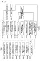
図1は、本実施形態に係る走行制御装置100の構成を示す図である。図1に示すように、本実施形態に係る走行制御装置100は、周囲検出センサ110と、自車位置検出装置120と、地図データベース130と、提示装置140と、駆動制御装置150と、制御装置160とを有している。これら装置は、相互に情報の授受を行うためにCAN(Controller Area Network)その他の車載LANによって接続されている。
<< First Embodiment >>
FIG. 1 is a diagram illustrating a configuration of a travel control device 100 according to the present embodiment. As illustrated in FIG. 1, the travel control device 100 according to the present embodiment includes a surrounding detection sensor 110, a vehicle position detection device 120, a
周囲検出センサ110は、自車両の周囲に存在する障害物(他車両など)や道路標識(レーンマークや縁石など)を検出する。周囲検出センサ110としては、たとえば、自車両の前方を撮像する前方カメラ、自車両の後方を撮像する後方カメラ、自車両の側方を撮像する側方カメラなどを用いることができる。また、周囲検出センサ110として、自車両の周囲の障害物を検出するレーザー距離計(LRF:Laser Range Finder)を用いることもできる。周囲検出センサ110の検出範囲(距離、角度)は、センサの種類によって異なる例えば、レーダの場合には、100〜200メートルの距離に存在する物体は検出できるものの、検出角度が非常に狭角(数十度)である。レーザーレンジファインダーの場合には、100メートル以下と比較的距離が短いものの、検出角度が広角であり、測距性能が優れている。また、カメラの場合には、画像を処理するプログラムの性能に依存する傾向がある。なお、周囲検出センサ110として、上述した複数のセンサのうち1つのセンサを用いる構成としてもよいし、2種類以上のセンサを組み合わせて用いる構成としてもよい。2種類以上のセンサを組み合わせて用いた場合には、各センサによって検出された物体を全て取り扱うこともよく、位置や挙動などから、同一の物体であることが理解できた場合には、重複する物体を取り除いてもよい。周囲検出センサ110の検出結果は、制御装置160に出力される。
The surrounding detection sensor 110 detects obstacles (such as other vehicles) and road signs (such as lane marks and curbs) existing around the host vehicle. As the surrounding detection sensor 110, for example, a front camera that images the front of the host vehicle, a rear camera that images the rear of the host vehicle, a side camera that images the side of the host vehicle, and the like can be used. Further, as the surrounding detection sensor 110, a laser rangefinder (LRF) that detects obstacles around the host vehicle can be used. The detection range (distance, angle) of the surrounding detection sensor 110 varies depending on the type of sensor. For example, in the case of radar, an object existing at a distance of 100 to 200 meters can be detected, but the detection angle is very narrow ( Dozens of degrees). In the case of a laser range finder, although the distance is relatively short at 100 meters or less, the detection angle is wide and the ranging performance is excellent. In the case of a camera, it tends to depend on the performance of a program that processes images. In addition, as the surrounding detection sensor 110, it is good also as a structure which uses one sensor among the some sensors mentioned above, and is good also as a structure which uses 2 or more types of sensors in combination. When two or more types of sensors are used in combination, all the objects detected by each sensor may be handled, and if it is understood from the position and behavior that they are the same object, they will overlap. The object may be removed. The detection result of the surrounding detection sensor 110 is output to the
自車位置検出装置120は、GPSユニット、ジャイロセンサ、および車速センサなどから構成されており、GPSユニットにより複数の衛星通信から送信される電波を検出し、対象車両(自車両)の位置情報を周期的に取得するとともに、取得した対象車両の位置情報と、ジャイロセンサから取得した角度変化情報と、車速センサから取得した車速とに基づいて、対象車両の現在位置を検出する。自車位置検出装置120により検出された対象車両の位置情報は、制御装置160に出力される。
The own vehicle position detection device 120 includes a GPS unit, a gyro sensor, a vehicle speed sensor, and the like, detects radio waves transmitted from a plurality of satellite communications by the GPS unit, and obtains position information of the target vehicle (own vehicle). The current position of the target vehicle is detected based on the acquired position information of the target vehicle, the angle change information acquired from the gyro sensor, and the vehicle speed acquired from the vehicle speed sensor. The position information of the target vehicle detected by the own vehicle position detection device 120 is output to the
地図データベース130は、道路情報を含む地図情報(地図データ)を記憶している。道路情報には、道路の車線を区画する車線境界の情報、交差点、停止線、および横断歩道の情報、道路形状に関する情報(たとえばカーブであるかなど)、道路の曲率に関する情報が含まれる。地図データベース130は、これら道路情報を地図上の位置に関連付けて記憶している。これにより、走行制御装置100は、地図データベース130を参照することで、自車両の走行予定経路上の各位置における、車線境界、交差点、停止線、横断歩道、道路形状、および道路曲率の情報を取得することができる。また、車線境界の情報には、車線境界がレーンマークまたは縁石であるか、レーンマークである場合には、車線境界の色(たとえば白色や黄色など)や種類(二重線、実線、点線など)の情報がさらに含まれている。
The
提示装置140は、たとえば、ナビゲーション装置が備えるディスプレイ、ルームミラーに組み込まれたディスプレイ、メーター部に組み込まれたディスプレイ、フロントガラスに映し出されるヘッドアップディスプレイ、あるいは、オーディオ装置が備えるスピーカーなどの装置である。 The presentation device 140 is a device such as a display provided in a navigation device, a display incorporated in a room mirror, a display incorporated in a meter unit, a head-up display projected on a windshield, or a speaker provided in an audio device. .
駆動制御装置150は、自車両の走行を制御する。たとえば、駆動制御装置150は、自車両が先行車両に追従する場合には、自車両と先行車両との車間距離が一定距離となるように、加減速度および車速を実現するための駆動機構の動作(エンジン自動車にあっては内燃機関の動作、電気自動車系にあっては電動モータ動作を含み、ハイブリッド自動車にあっては内燃機関と電動モータとのトルク配分も含む)およびブレーキ動作を制御する。また、自車両が車線変更を行う場合や、交差点を右折または左折する場合には、ステアリングアクチュエータの動作を制御して、車輪の動作を制御することで、自車両の転回制御を実行する。なお、駆動制御装置150による走行制御方法としては、その他の周知の方法を用いることもできる。 The drive control device 150 controls traveling of the host vehicle. For example, when the own vehicle follows the preceding vehicle, the drive control device 150 operates the drive mechanism for realizing acceleration / deceleration and vehicle speed so that the distance between the own vehicle and the preceding vehicle is a constant distance. It controls the operation of the internal combustion engine in the case of an engine vehicle, the operation of an electric motor in the case of an electric vehicle system, and the torque distribution between the internal combustion engine and the electric motor in the case of a hybrid vehicle. Further, when the host vehicle changes lanes or turns right or left at an intersection, the turning control of the host vehicle is executed by controlling the operation of the steering actuator and the wheel. In addition, as a traveling control method by the drive control device 150, other known methods can be used.
また、駆動制御装置150は、後述する制御装置160により出力された車線境界の情報に基づいて、自車両の走行を制御する。たとえば、駆動制御装置150は、制御装置160により出力された車線境界の情報に基づいて、自車両の走行予定経路の車線を把握することで、自車両が走行予定経路の車線内を走行するように、自車両の走行を制御することができる。また、駆動制御装置150は、制御装置160により出力された車線境界の情報に基づいて、自車両が走行する地図上の位置(たとえば、右折車線、交差点、横断歩道手前など)を把握することで、自車両の行動(たとえば停止、加速、右折、左折など)を適切に決定することができる。
Further, the drive control device 150 controls the travel of the host vehicle based on the information on the lane boundary output by the
制御装置160は、自車両の走行を制御するためのプログラムを格納したROM(Read Only Memory)と、このROMに格納されたプログラムを実行するCPU(Central Processing Unit)と、アクセス可能な記憶装置として機能するRAM(Random Access Memory)とから構成される。なお、動作回路としては、CPU(Central Processing Unit)に代えて又はこれとともに、MPU(Micro Processing Unit)、DSP(Digital Signal Processor)、ASIC(Application Specific Integrated Circuit)、FPGA(Field Programmable Gate Array)などを用いることができる。
The
制御装置160は、ROMに格納されたプログラムをCPUにより実行することにより、自車両の予定走行経路を探索する経路探索機能と、地図情報から車線の境界線を取得する地図境界線取得機能と、周囲検出センサ110による検出結果に基づいて車線の境界線を取得するセンサ境界線取得機能と、センサ境界線取得機能により検出された車線の連続性を評価する連続性評価機能、地図情報に基づいて取得された車線境界と、周囲検出センサ110の検出結果に基づいて検出された車線境界とを統合する境界線統合機能と、統合した車線境界の情報を出力する出力機能と、を実現する。以下において、制御装置160が備える各機能について説明する。
The
制御装置160の経路探索機能について説明する。制御装置160は、自車両の現在位置および目的地から、自車両の走行予定経路を算出する。目的地は、例えば、図示しない入力装置からドライバーにより入力される。制御装置160は、カーナビゲーションに見られるような走行経路計算に加えて、車線レベルでの走行予定経路を算出する。具体的な計算方法としては、ダイキストラ法やA*などのグラフ探索理論に基づく手法を用いることが考えられる。各車線に対して、リンクとノードが地図上で予め設定されている。リンクは走行経路を意味しており、ノードはリンク同士の接続点である。リンクには重みが付与されており、重みは目的地に向かう際に走行すべき車線に対応する推奨リンクか否かによって変更される。そして、制御装置160は、現在の自車位置から目的地までの重みの総和が小さくなる車線を走行予定経路として算出する。なお、経路探索は、上記方法に限らず、公知の方法でもよい。
The route search function of the
制御装置160の地図境界線取得機能について説明する。制御装置160は、地図データベース130に記憶された地図情報に基づいて、自車線を含む車線の境界線(以下、車線境界とも称す)を検出する。車線境界とは、レーンマーク(車線を区画するために道路上に白色、オレンジ、または黄色などで描かれた実線、二重線、破線など)や、縁石やガードレールなど、車線とそれに隣接する車線、あるいは、車線と路肩との境界を定める線である。地図データベース130が記憶する地図情報には、各車線の形状情報が含まれており、地図境界線検出機能は、形状情報を参照して、自車線を含む車線の車線境界を地図情報から検出することができる。なお、地図境界線検出機能により検出される車線境界は、自車両の周囲の車線に限定されず、たとえば、自車両の走行予定経路における車線の車線境界を検出することもできる。これにより、制御装置160は、地図データを用いて、車線境界の情報を取得する。なお、以下においては、地図境界線検出機能により検出された車線境界を地図境界線として説明する。
The map boundary line acquisition function of the
制御装置160のセンサ境界線検出機能について説明する。制御装置160は、周囲検出センサ110による検出結果に基づいて自車両の周囲の車線の車線境界を検出する。たとえば、制御装置160は、自車両の周囲に存在するレーンマーク、縁石、ガードレールを、前方カメラ、側方カメラ、または後方カメラにより撮像し、撮像画像の画像処理により、自車両の周囲の車線の車線境界を検出する。制御装置160は、時系列での画像の特徴点の移動量を算出することで車線の位置を検出し、複数のカメラをステレオカメラのように用いることで車線の凹凸を検出することができる。これにより、制御装置160は、周囲検出センサ110を用いて、車線境界の位置と形状を検出することができる。また、制御装置160、レーザーレンジファインダーを用いて、自車両の周囲の路面やレーンマークの輝度、あるいは、測距により縁石の凸部を検出することで、自車両の周囲の車線の車線境界を検出することができる。路面やレーンマークの輝度は反射強度から測定することができ、縁石の凸部はレーザーレンジファインダーによる測距結果から測定できる。
The sensor boundary line detection function of the
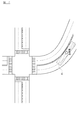
カメラにより、レーンマーク、縁石、ガードレールなどを高精度に検出できる範囲は、カメラからおおよそ数十メートルの範囲となる。また、レーザー距離計を用いて、レーンマークや縁石を識別することもできる。しかし、この場合も、路面に描かれたレーンマークの輝度を検出するために、レーザー距離計を下向きに設置する必要があり、また、レーザー距離計で縁石の微小な凸部を検出するためには、やはりレーザー距離計を下向きに設置する必要がある。そのため、レーザー距離計を用いた場合も、レーンマークや縁石を高精度に検出できる範囲は、レーザー距離計からおおよそ数十メートルの範囲となる。このように、センサ境界線検出機能で車線境界を検出可能な範囲は、図2に示すように、自車両から数十メートルの範囲となる。図2は、周囲検出センサ110の検出範囲Aを説明するための図である。また、以下においては、センサ境界線検出機能により検出された車線境界をセンサ境界線として説明する。 The range in which lane marks, curbs, guardrails, and the like can be detected with high accuracy by the camera is approximately a few tens of meters from the camera. Lane marks and curbs can also be identified using a laser distance meter. However, in this case as well, it is necessary to set the laser distance meter downward in order to detect the brightness of the lane mark drawn on the road surface. In addition, in order to detect the minute convex part of the curb with the laser distance meter Still need to install the laser rangefinder downwards. Therefore, even when a laser distance meter is used, the range in which lane marks and curbs can be detected with high accuracy is approximately a few tens of meters from the laser distance meter. Thus, the range in which the lane boundary can be detected by the sensor boundary line detection function is a range of several tens of meters from the host vehicle, as shown in FIG. FIG. 2 is a diagram for explaining the detection range A of the surrounding detection sensor 110. In the following description, a lane boundary detected by the sensor boundary line detection function is described as a sensor boundary line.
図2に示すように自車両が片側2車線のカーブ状の道路を走行している場合に、周囲検出センサ110の検出範囲には、実線の車線境界DRと破線の車線境界DLが含まれている。車線境界DRは、自車両の進行方向に対して自車両の右側に位置する車線境界を示しており、車線境界DLは、自車両の進行方向に対して自車両の右側に位置する車線境界を示している。制御装置160は、センサ境界線を、点群で表現された車線境界として検出する。センサ境界線の情報は、空間的に離散した情報となる。図3は、点群で表現されたセンサ境界線を説明するための図である。センサ境界線の位置情報を、地図上に分布した場合に、センサ境界線の情報は図3に示すような位置の離散値で表すことができる。これにより、制御装置160は、周囲検出センサ110を用いて、自車両の周囲の環境から自車両の周囲の車線境界情報を取得する。
When the vehicle as shown in FIG. 2 is traveling on a curved shape of a road with two lanes, the detection range of the ambient sensor 110, includes solid line lane boundary D R and dashed lane D L It is. Lane boundary D R, indicates a lane boundary on the right side of the vehicle with respect to the traveling direction of the vehicle, lane boundary D L is positioned on the right side of the vehicle relative to the traveling direction of the own vehicle lane Indicates the boundary. The
制御装置160は、地図境界線取得機能により取得した車線境界情報と、センサ境界線取得機能により取得した車線境界情報とを統合して、車線境界情報を生成する。ここで、図2に示すように、センサ境界線を高精度に検出できる範囲は、自車両の周囲の範囲であり、自車両から離れるほど車線境界の検出精度は低くなる。そこで、本実施形態では、センサ境界線検出機能で車線境界を検出できる検出範囲の外側の領域については、地図境界線検出機能で検出した車線境界(地図境界線)を用いて補完する。
The
図3に示すように、センサ境界線の検出結果は、空間的に離散した情報で表される。そのため、センサの誤差や、センサに対する外乱の入力がなければ、空間的に離散した位置情報は連続性をもっており、位置情報で示される点座標をつなげることで、走行車線に沿った曲線を形成することができる。実際には、センサ検出線の位置情報は、センサ誤差又は外乱等を起因とした誤差を含むことがある。そのため、センサ境界線の検出結果である位置情報の連続性が保たれていないことも考えられる。連続性の低い状態のセンサ境界線の情報と地図境界線の情報が統合された場合には、統合された車線境界の信頼度は低くなる。 As shown in FIG. 3, the detection result of the sensor boundary line is represented by spatially discrete information. Therefore, if there is no sensor error or disturbance input to the sensor, spatially discrete position information has continuity, and a curve along the driving lane is formed by connecting point coordinates indicated by the position information. be able to. Actually, the position information of the sensor detection line may include an error caused by a sensor error or a disturbance. For this reason, the continuity of the position information, which is the detection result of the sensor boundary line, may not be maintained. When the sensor boundary information and the map boundary information in a low continuity state are integrated, the reliability of the integrated lane boundary is low.
そこで、本実施形態では、センサ境界線の情報と地図境界線の情報とを統合するか否かを判断するための条件として、制御装置160は、センサ境界線の連続性を評価している。センサ境界線の連続性の評価は以下の方法で行われる。
Therefore, in the present embodiment, the
制御装置160の連続性評価機能を説明する。制御装置160は、自車両が現在走行している道路の形状に適合する曲線モデルを決定する。曲線モデルは、道路形状をモデル化したものである。制御装置160は、少なくとも周囲検出センサ110の検出範囲Aに含まれる車線境界の境界線モデルを、曲線モデルとして決定する。曲線モデルは、走行車線の道路属性、車線の曲率、走行車線の制限速度、又は、道路地物の情報により決まる。
The continuity evaluation function of the
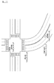
制御装置160は、地図データに含まれる道路情報を用いて、曲線モデルを決定する。地図データには、高速道路や一般道路などといった道路属性が記憶されている。高速道路は、高い速度で走行することを目的とした道路であるため、直線的な道路形状になっている。言い換えると、高速道路の形状は、直線、又は、3次曲線で近似可能な曲線になっている。一方、一般道路は、急なカーブ、不連続な箇所、交差点などの特徴的な箇所を含む道路形状となっている。例えば、自車両が高速道路を走行している場合には、制御装置160は、地図データに記憶されている道路情報のうち、自車両の走行中の道路の情報を特定し、当該道路情報の中から属性情報を抽出する。制御装置160は、属性情報から、現在の道路が高速道路であることを特定でき、曲線モデルを高速道路用の曲線モデルに決定する。曲線モデルは、道路情報の種類に応じて、地図データベース130に記録されている。地図データには、道路属性に限らず、道路の曲率又は制限速度の情報も含まれている。制御装置160は、地図データから、現在走行中の道路の曲率を抽出し、曲率パラメータで示される曲線形状を曲線モデルに決定する。制御装置160は、制限速度を抽出し、制限速度に対応した曲率をもつ曲線を曲線モデルに決定してもよい。制限速度が高い道路ではカーブの曲率は小さくなり、制限速度と道路の曲率の間には相関性がある。そのため、制御装置160は、制限速度が高いほど、曲率の小さい曲線を曲線モデルに決定する。また、地図データには、交差点、信号機、横断歩道の有無など、道路地物に関する情報が含まれている。例えば、交差点、信号機、横断歩道がある場合には、道路属性が一般道路になる。そのため、制御装置160は、自車両の走行中の道路の情報から、交差点等を抽出した場合には、一般道路用の曲線モデルに決定する。図4は、曲線モデルを説明するための図である。自車両が、図2に示すような交差点につながる曲線を走行している場合に、制御装置160は、地図データから現在走行中の道路の道路情報を特定し、道路情報から道路属性等を抽出し、図4の点線MR、MLで表される曲線を曲線モデルとして決定する。
The
次に、制御装置160は曲線モデルに対する位置の誤差分布を算出する。誤差分布は、曲線モデルで表される曲線に対して、センサ境界線のずれ量の許容範囲を表している。例えば、自車両が高速道路を走行している場合に、曲線モデルは、曲率の小さい曲線となる。そして、周囲検出センサ10の検出結果の精度が高い場合には、センサ境界線の形状は、同様に、曲率の小さい曲線となる。つまり、センサ境界線の形状は曲線モデルで近似できる。また、センサ境界線の離散値を曲線モデルの位置を中心に分布した場合には、曲線モデルの形状とセンサ境界線の形状との一致度が高いほど、離散値は誤差分布の範囲内に収まる。一方、外乱等によって、周囲検出センサ10の検出結果の精度が低い場合には、センサ境界線の離散値は、曲線モデルの付近に分布せず、センサ境界線のずれ量が大きくなる。曲線モデルの形状とセンサ境界線の形状との一致度が低い場合には、センサ境界線の離散値は誤差分布の範囲外になる。
Next, the
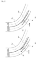
制御装置160は、地図データを用いて、曲線モデルに対する位置の誤差分布を算出する。例えば、高速道路においては、道路構造が単純な形状となっており、かつ、同様の道路構造となっているため、曲線モデルに対する誤差分布は、比較的狭い範囲で表される。一方、一般道路においては、道路構造が複雑な形状になっているため、曲線モデルに対する誤差分布は、高速道路の時と比べて、広い範囲で表される。図5及び図6は、曲線モデルに対する位置の誤差分布を説明するための図である。図5(а)及び図6(а)は、高速道路の誤差分布を表している。図5(b)及び図6(b)は、一般道路の誤差分布を表している。図5では、誤差部分は、点線の車線境界を中心とした幅の大きさで表されている。図6では、誤差分布はグラフで表される。グラフの横軸は、車線境界を中心として、離散値の位置のずれ量を表している。縦軸は離散値の数を表している。
The
なお、曲線モデルに対する誤差分布は、道路属性に限らず、道路の曲率や制限速度情報、交差点、信号機、停止線、横断歩道の有無に基づいて算出されてもよい。例えば、道路属性が高速道路である場合でも、分合流箇所では、道路構造が複雑な形状となっており、かつ、多種多様な道路構造となっている。このような場合には、例えば誤差分布を、一般道路のように広めの範囲になるように、制御装置160は誤算分布を算出する。
Note that the error distribution for the curve model is not limited to road attributes, but may be calculated based on road curvature and speed limit information, intersections, traffic lights, stop lines, and the presence of crosswalks. For example, even when the road attribute is an expressway, the road structure has a complicated shape and a wide variety of road structures at the junction. In such a case, for example, the
制御装置160は、周囲検出センサ110を用いて、車線境界を点群で表現される離散値で検出すると、センサ境界線の各離散値を、曲線モデルに対する位置の誤差分布上に、分布する。このとき、離散値の位置座標は、曲線モデルを中心とした相対的な座標で表されるため、離散値の位置座標は、曲線モデルの位置に対するずれ量に相当する。そして、誤差分布上で分布された離散値が、誤差分布の範囲内に含まれる場合には、制御装置160は、センサ境界線の形状が曲線モデルで近似できると判定し、センサ境界線の空間的な連続性の評価値が高いと判定する。一方、離散値が、誤差分布の範囲外である場合には、制御装置160は、センサ境界線の形状が曲線モデルで近似できないと判定し、センサ境界線の空間的な連続性の評価値が低いと判定する。
When the lane boundary is detected by a discrete value represented by a point group using the surrounding detection sensor 110, the
制御装置160の境界線統合機能について説明する。制御装置160は、ICP(Iterative Closest Point)の手法により、周囲検出センサ110により検出されたセンサ境界線と、地図情報に基づく地図境界線との合致度を判定する。ICPとは、「周囲検出センサ110により検出されたセンサ境界線を示す点群」と「地図情報が有する地図境界線を示す点群」との位置合わせを、最小二乗法に基づいて行うものである。
The boundary line integration function of the
制御装置160は、センサ境界線と地図境界線との位置合わせを行うために、センサ境界線と地図境界線との共通部分を特定する。センサ境界線を取得する際に、制御装置160が、周囲検出センサ110を用いて、信号機等の地物を検出しており、検出された地物の情報が地図データに含まれている場合には、地物の位置情報が、センサ検出と地図データとの間で共通した部分となる。そのため、制御装置160は、当該地物を、センサ境界線と地図境界線との共通部分として特定し、地物の位置に基づいて、センサ境界線と地図境界線との位置合わせを行う。共通部分は、交差点などの地物に限らず、車線の共通部分であってもよい。
The
図7は、センサ境界線と地図境界線との統合を説明するための図である。点線PRは自車両の右側に位置するセンサ境界線を表し、点線PLは自車両の左側に位置するセンサ境界線を表す。実線QRは自車両の右側の地図境界線を示し、点線QLは自車両の左側の地図境界線を示す。センサ境界線と地図境界線との共通部分を基準としつつ、センサ境界線と地図境界線の位置合わせを行うと、センサ境界線を示す点群(離散値)を結んだ線は、地図境界線に沿って延長した線となる。すなわち、自車両の右側では点線PRと実線QRが結ばれ、自車両の左側では点線PLと点線QLが結ばれることで、センサ境界線と地図境界線が統合される。 FIG. 7 is a diagram for explaining integration of a sensor boundary line and a map boundary line. Dotted P R represents the sensor boundary line located on the right side of the vehicle, the dotted line P L represents the sensor boundary line located on the left side of the vehicle. The solid line Q R represents the right map boundary of the vehicle, a dotted line Q L denotes a map boundary of the left side of the vehicle. When the sensor boundary line and the map boundary line are aligned while using the common part of the sensor boundary line and the map boundary line as a reference, the line connecting points (discrete values) indicating the sensor boundary line is the map boundary line. The line extends along the line. That is, in the right side of the vehicle are linked by a dotted line P R and solid Q R, in the left side of the vehicle by the dotted line P L and the dotted line Q L is tied, the sensor borders and map boundary are integrated.
続いて、図8を参照して、第1実施形態に係る走行制御処理について説明する。図8は、第1実施形態に係る走行制御処理を示すフローチャートである。 Next, the travel control process according to the first embodiment will be described with reference to FIG. FIG. 8 is a flowchart showing a travel control process according to the first embodiment.
ステップS101では、制御装置160は、経路探索機能により自車両の現在位置を検出する。ステップS102では、制御装置160は、経路探索機能より走行予定経路の探索を行い、自車両の走行予定経路を取得する。たとえば、経路探索機能は、ステップS101で取得した自車両の位置情報に基づいて、自車両の現在位置から目的地までの走行予定経路を探索する。また、経路探索機能は、自車両が走行する道路だけではなく、自車両が走行する車線に基づいて、自車両の走行予定経路を探索する。
In step S101, the
ステップS103では、制御装置160は、地図境界線検出機能により、地図境界線を検出する。本実施形態では、地図データベース130に、各車線の車線境界の情報が、地図上の位置に関連付けて記憶されている。
In step S103, the
ステップS104では、制御装置160は、周囲検出センサ110を用いて、自車両の周囲の状況を検出する。ステップS105では、制御装置160は、センサ境界線検出機能により、周囲検出センサ110の検出結果に基づいて、センサ境界線を検出する。なお、図2に示すように、周囲検出センサ110によるセンサ境界線の検出範囲は、自車両から所定距離(たとえば数十メートル)以内の範囲、すなわち、自車両の周囲の範囲となる。
In step S <b> 104, the
ステップS106では、制御装置160は、連続性評価機能により地図境界線の曲線モデルを決定する。ステップ107では、制御装置160は、連続性評価機能により、曲線モデルに対する誤差分布を算出する。なお、制御装置160は、地図データに含まれる道路情報に限らす、周囲検出センサ110の検出結果に基づき誤差分布を算出してもよい。例えば、制御装置160は、周囲検出センサ110の検出結果から、道路属性を取得できる場合には、地図データに格納されている道路属性の代わりに、検出された道路属性に基づき、誤差分布を算出する。
In step S106, the
ステップS108では、制御装置160は、連続性評価機能により、車線境界の空間的な連続性を評価する。ステップS109では、制御装置160は、連続性の評価が高いか否かを判定する。連続性の評価値は、センサ境界線の形状と曲線モデルとの近似度で表される。センサ境界線の形状が曲線モデルと近似しているほど、評価値は高くなる。そして、評価値が評価閾値より高い場合には、制御装置160は、センサの境界線の形状と曲線モデルが近似していると判定でき、センサ境界線は空間的な連続性を有しているため、制御装置160は、センサ境界線の情報の信頼度は高いと判定する。なお、センサ境界線の形状と曲線モデルが近似している場合には、センサ境界線の形状と曲線モデルが一致している場合も含む。そして、制御装置160はステップS110の制御フローを実行する。
In step S108, the
一方、連続性の評価が低い場合には、センサ境界線は空間的な連続性を有していないため、制御装置160は、センサ境界線の情報の信頼度は低いと判定する。そして、制御フロー160は、信頼度の低いセンサ境界線情報を用いることなく、ステップS118以降の制御フローを実行する。
On the other hand, when the evaluation of continuity is low, the sensor boundary line does not have spatial continuity, and thus the
ステップS110では、制御装置160は、センサ境界線と自車両の相対距離を算出する。図9は、相対距離dwを説明するための図である。相対距離dwはセンサ境界線の位置と自車両の現在位置との間の距離である。制御装置160は、自車両に対して側方の方向に検出された車線境界までの距離を、相対距離dwとして算出する。
In step S110, the
ステップS111では、制御装置160は、算出された相対距離dwが所定の距離閾値より大きいか否かを判定する。ここで、所定の距離閾値は、一般的な車線の幅(例えば、3メートル程度)に相当する。相対距離dwが距離閾値より大きい場合には、センサ境界線の離散値の位置が、自車両の現在位置に対して、車線の幅よりも遠い箇所にあり、センサ境界線の情報の信頼度が低い可能性がある。一方、相対距離dwが距離閾値以下である場合には、センサ境界線の情報の信頼度は高い。センサ境界線の情報の信頼度が低い可能性がある場合には、制御装置160は、ステップS112〜S114の制御フローを実行することで、自車両の走行軌跡の評価を行う。一方、センサ境界線の情報の信頼度が高い場合には、制御装置160は、走行軌跡の評価処理を行うことなく、ステップS115の制御フローを実行する。
In step S111, the
ステップS112では、制御装置160は自車両の走行軌跡を取得する。制御装置160は、自車両が現在位置に至るまでの自車両の位置情報を時系列で記録している。制御装置160は、時系列で記録された位置情報を読み出し、当該位置情報で示される位置座標を線で結ぶことで、走行軌跡を算出できる。
In step S112, the
ステップS113では、制御装置160は、自車両の走行軌跡と同一地点における、他車両の走行軌跡(統計データ)を取得する。例えば、制御装置160は、カメラを用いて、自車両の前方又は後方を走行する他車両を検出し、位置情報を他車両の走行軌跡の情報として記録する。他車両が走行した際の車両走行軌跡が複数存在する場合には、制御装置160は各走行軌跡の分析を行う。例えば、他車両が走行した際の走行軌跡の分布から、正常値と異常値の判断を行い、正常値のみを抽出して平均値を取得することによって、統計的に正しい車両走行軌跡を取得することができる。
In step S113, the
ステップS114では、制御装置160は、自車両の走行軌跡と他車両の走行軌跡の一致度が高いか否かを判定する、走行軌跡の一致度は、例えば、一致度の評価手法としては、自車両の走行軌跡と他車両の走行軌跡との差分が、所定の誤差範囲内に収まっているか否かによって判定される。走行軌跡の一致度が高い場合には、車線境界の情報の信頼度は高く、制御フロー160はステップS115〜ステップ117の制御フローを実行する。例えば、自車両が通常よりも広い車線幅の道路を走行している場合には、車線境界は、自車両の側方の方向で、通常の車線幅より遠い位置で検出される。車両の走行軌跡は、自車両と他車両で同様の傾向を示すため、周囲検出センサ110によって検出された車線境界情報が、信頼度の高い情報であることが分かる。一方、走行軌跡の一致度が低い場合には、自車両が本来の走行車線から逸脱している時に、周囲検出センサ110が車線を検出している可能性があり、センサ境界線の情報の信頼度は低くなるため、制御フロー160はステップS118、S119の制御フローを実行する。
In step S114, the
ステップS115では、制御装置160は、センサ境界線の情報(車線境界情報)の信頼度が高いと判定する。ステップS116では、制御装置160は、地図データから取得された車線境界情報と、周囲検出センサ110の検出結果から取得された車線境界情報とを統合する。ステップS117では、制御装置160は、統合された車線情報に、車線の付随情報を付加した上で、車線情報を出力する。車線の付随情報は、道路の曲率、制限速度情報、交差点、信号機、停止線、横断歩道などである。なお、統合された車線境界の情報は、自車両に搭載されたセンサによって検出された車線境界情報であろうと、地図データに含まれる車線境界情報であろうと、車線境界情報の出所を問わず、同じフォーマットで定義された車線境界情報である。そして、制御装置160は、図8に示す制御フローを終了する。
In step S115,
ステップS118では、制御装置160は、センサ境界線の情報(車線境界情報)の信頼度が低いと判定する。ステップS116の制御フローにより、車線境界の情報の信頼度が低いと判定された場合には、センサによって検出された車線境界情報が、自車両に対する最寄りの車線境界情報ではない可能性がある。そのため、誤って検出された車線境界情報を使用することがないように、制御装置160は、車線境界の情報の信頼度を評価している。ステップS119では、制御装置160は、センサ境界線の車線境界情報を用いることなく、地図データから取得される境界線情報を車線情報として出力する。そして、制御装置160は、図8に示す制御フローを終了する。
In step S118, the
上記のように、本実施形態では、周囲検出センサ110を用いて、自車両の周囲の実際の環境から自車両の周囲の車線境界の情報を実境界線情報として取得し、少なくとも車線の形状情報を含む地図データを用いて、形状情報により特定される車線境界を地図境界線情報として取得する。そして、実境界線情報と地図境界線情報とを比較して、実境界線情報で示される車線の空間的な連続性を評価する。連続性の評価が高い場合には、実境界線情報と地図境界線情報とを統合し、統合された車線情報を出力する。一方、連続性の評価が低い場合には、地図境界線情報を車線情報として出力する。これにより、取得した車線境界の連続性を評価した上で、車線境界の検出結果と地図データに記憶された車線境界情報を統合するため、実際の状況に即した、精度の高い車線情報を提供することができる。また、自車周辺では自車に搭載されたセンサによる車線境界情報の検出結果を利用し、自車周辺から離れた場所では、地図データに格納された車線境界情報を利用することができるため、実際の走行環境を把握しつつ、将来の走行環境も推定することができる。 As described above, in this embodiment, the surrounding detection sensor 110 is used to acquire information on the lane boundary around the host vehicle as actual boundary information from the actual environment around the host vehicle, and at least the shape information of the lane The lane boundary specified by the shape information is acquired as map boundary line information using map data including. Then, the actual boundary information and the map boundary information are compared to evaluate the spatial continuity of the lane indicated by the actual boundary information. When the continuity evaluation is high, the actual boundary information and the map boundary information are integrated, and the integrated lane information is output. On the other hand, if the evaluation of continuity is low, map boundary information is output as lane information. As a result, the continuity of the acquired lane boundary is evaluated, and the lane boundary detection result and the lane boundary information stored in the map data are integrated to provide highly accurate lane information in line with the actual situation. can do. In addition, the lane boundary information stored in the map data can be used at locations away from the vicinity of the vehicle, using the detection result of the lane boundary information by the sensor mounted on the vehicle in the vicinity of the vehicle. The future driving environment can be estimated while grasping the actual driving environment.
また本実施形態では、地図データを用いて車線境界の曲線モデルを取得し、実境界線情報で示される車線境界(センサ境界線)の形状が曲線モデルで近似できる場合には、連続性が高いと評価する。これにより、センサによる車線境界情報の検出結果の信頼性を判断することができる。 In the present embodiment, a lane boundary curve model is acquired using map data, and the continuity is high when the shape of the lane boundary (sensor boundary line) indicated by the actual boundary information can be approximated by the curve model. And evaluate. Thereby, the reliability of the detection result of the lane boundary information by the sensor can be determined.
また本実施形態では、地図データを用いて、曲線モデルに対する位置の誤差分布を算出し、実境界線情報で示される車線境界(センサ境界線)と曲線モデルとの誤差が誤差分布内である場合には、実境界線情報で示される車線境界(センサ境界線)の形状が前記曲線モデルで近似できると判定する。これにより、自車位置に基づき最適な曲線モデルを利用して、センサによる車線境界情報の検出結果の信頼性を判断することができる。 In the present embodiment, the position error distribution with respect to the curve model is calculated using the map data, and the error between the lane boundary (sensor boundary line) indicated by the actual boundary information and the curve model is within the error distribution. Is determined that the shape of the lane boundary (sensor boundary line) indicated by the actual boundary line information can be approximated by the curve model. Thereby, the reliability of the detection result of the lane boundary information by the sensor can be determined using an optimal curve model based on the vehicle position.
また本実施形態では、地図データに含まれる車線の道路属性に基づき曲線モデルを決定する。これにより、例えば道路属性が高速道路であれば直線もしくはほぼ直線の曲線モデルを利用し、道路属性が一般道路であれば曲率半径が小さい曲線モデルを利用して、センサによる車線境界情報の検出結果の信頼性を判断することができる。 In this embodiment, the curve model is determined based on the road attribute of the lane included in the map data. Thus, for example, if the road attribute is a highway, a straight or almost straight curve model is used, and if the road attribute is a general road, a curve model with a small radius of curvature is used, and the detection result of the lane boundary information by the sensor Can be determined.
また本実施形態では、地図データに含まれる車線の曲率に基づき曲線モデルを決定する。これにより、センサによる車線境界情報の検出結果の信頼性を判断することができる。 In this embodiment, a curve model is determined based on the curvature of the lane included in the map data. Thereby, the reliability of the detection result of the lane boundary information by the sensor can be determined.
また本実施形態では、自車両の位置周辺の制限速度に基づき曲線モデルを決定する。これにより、制限速度から算出される許容される曲率半径を利用して、センサによる車線境界情報の検出結果の信頼性を判断することができる。 In the present embodiment, the curve model is determined based on the speed limit around the position of the host vehicle. Thereby, the reliability of the detection result of the lane boundary information by the sensor can be determined using the allowable radius of curvature calculated from the speed limit.
また本実施形態では、地図データに含まれる道路情報に基づき曲線モデルを決定する。これにより、センサによる車線境界情報の検出結果の信頼性を判断することができる。 In this embodiment, a curve model is determined based on road information included in the map data. Thereby, the reliability of the detection result of the lane boundary information by the sensor can be determined.
また本実施形態では、実境界線情報で示される車線境界(センサ境界線)の位置と自車両の現在位置との間の距離を算出し、算出された距離が所定の距離閾値より小さい場合には、実境界線情報と地図境界線情報とを統合し、統合された車線情報を出力し、算出された距離が所定の距離閾値より大きい場合には、地図境界線情報を車線情報として出力する。これにより、検出されたセンサ境界線の位置が自車両から遠い場合には、隣接車線の境界線の情報を除外した上で、車線情報を生成できる。 In this embodiment, the distance between the position of the lane boundary (sensor boundary line) indicated by the actual boundary line information and the current position of the host vehicle is calculated, and the calculated distance is smaller than a predetermined distance threshold. Integrates the actual boundary information and the map boundary information, outputs the integrated lane information, and outputs the map boundary information as the lane information when the calculated distance is larger than a predetermined distance threshold. . Thereby, when the position of the detected sensor boundary line is far from the host vehicle, the lane information can be generated after excluding the boundary line information of the adjacent lane.
また本実施形態では、他車両の走行軌跡と自車両の走行軌跡との差分が許容範囲内である場合には、実境界線情報と地図境界線情報とを統合し、統合された車線情報を出力し、差分が許容範囲外である場合には、地図境界線情報を車線情報として出力する。これにより、自車両の走行軌跡が統計的に正しい走行軌跡と同等であった場合に、車線境界情報を使用するため、センサによる車線境界の検出が困難な箇所においても、正しい車線境界情報を取得することができる。 Further, in the present embodiment, when the difference between the traveling locus of the other vehicle and the traveling locus of the own vehicle is within the allowable range, the actual boundary information and the map boundary information are integrated, and the integrated lane information is When the difference is outside the allowable range, the map boundary information is output as lane information. As a result, the lane boundary information is used when the vehicle's driving trajectory is statistically equivalent to the correct driving trajectory, so the correct lane boundary information is acquired even in locations where it is difficult to detect the lane boundary by the sensor. can do.
また本実施形態では、センサを用いて自車両の周囲に位置する地物の情報を取得し、地物の情報に基づき、実境界線情報で示される車線境界(センサ境界線)と地図境界線情報で示される車線境界(地図境界線)とを結合させる結合位置を決定し、実境界線情報で示される車線境界(センサ境界線)と地図境界線情報で示される車線境界(地図境界線)とを結合位置でつなげることで、実境界線情報と地図境界線情報とを統合する。これにより、センサによる車線境界の検出結果と、地図データに格納された車線境界を適切な箇所で統合するので、正しく、かつ、広範囲で、車両境界情報を提供することができる。また、車線境界を空間的な連続性を維持しつつ、それぞれの情報を統合するので、正しく、かつ、広範囲で、車両境界情報を提供することができる。 Further, in the present embodiment, information on features located around the host vehicle is acquired using a sensor, and a lane boundary (sensor boundary line) and a map boundary line indicated by actual boundary line information are obtained based on the feature information. Determine the connection position to connect the lane boundary (map boundary line) indicated by the information, and the lane boundary (sensor boundary line) indicated by the actual boundary information and the lane boundary (map boundary line) indicated by the map boundary information Are combined at the connection position to integrate the actual boundary information and the map boundary information. Thereby, since the detection result of the lane boundary by the sensor and the lane boundary stored in the map data are integrated at an appropriate location, vehicle boundary information can be provided correctly and in a wide range. Further, since the respective information is integrated while maintaining the spatial continuity of the lane boundary, the vehicle boundary information can be provided correctly and in a wide range.
≪第2実施形態≫
第2実施形態に係る走行制御装置について説明する。第2実施形態に係る走行制御装置100は、第1実施形態の走行制御装置100と同様の構成を有し、以下に説明するように動作すること以外は、第1実施形態と同様であり、第1実施形態の記載を適宜援用する。
<< Second Embodiment >>
A travel control apparatus according to the second embodiment will be described. The travel control apparatus 100 according to the second embodiment has the same configuration as the travel control apparatus 100 of the first embodiment, and is the same as the first embodiment except that it operates as described below. The description of the first embodiment is incorporated as appropriate.
制御装置160は、境界線統合機能として、センサ境界線と地図境界線とを位置合わせするためのオフセット量を算出する機能を有している。オフセット量は座標軸上の長さで表される。制御装置160は、センサ境界線を取得するときに用いた車線境界情報と、地図境界線を取得するときに用いた車線境界情報から、互いに共通している対象物を特定する。対象物は、表示機、信号機、建物、停止線、白線及び縁石等の地物である。制御装置160は、周囲検出センサ110の検出データから地物を検出し、自車両の現在位置から検出された地物までの距離を測定する。制御装置160は、地図データから、検出された地物の情報を特定する。地物の情報が特定できる場合には、特定された地物の情報は、周囲検出センサ110で検出可能な情報であり、かつ、地図データで管理されている情報となるため、共通の対象物となり得る。制御装置160は、地図データに含まれる地物の位置情報を用いて、自車両の現在位置から地物の位置までの距離を測定する。そして、センサにより検出された地物(対象物)の距離と、地図データで特定された地物(対象物)の距離が相違する場合には、距離の差分がオフセット値となる。制御装置160は、対象物の距離の違いからオフセット値を算出し、当該オフセット値に基づき、センサ境界線の情報と地図境界線の情報とを統合する。
The
次に、図10を参照して、第2実施形態に係る走行制御処理について説明する。図10は、第2実施形態に係る走行制御処理を示すフローチャートである。 Next, a travel control process according to the second embodiment will be described with reference to FIG. FIG. 10 is a flowchart showing a travel control process according to the second embodiment.
ステップS201〜ステップS209までの制御フローは、第1実施形態におけるステップS101〜ステップS109までの制御フローと同内容であるため、説明を省略する。 Since the control flow from step S201 to step S209 has the same content as the control flow from step S101 to step S109 in the first embodiment, description thereof is omitted.
連続性の評価が高い場合には、ステップS210では制御装置160はセンサ境界線の情報(車線境界情報)の信頼度が高いと判定する。ステップS211では、制御装置160は、周囲検出センサ110の検出結果から、標識、信号機、建物及び停止線のうち少なくとも1つの地物の情報を取得できた否かを判定する。例えば、制御装置160は、カメラの撮像画像に対して画像処理を行い地物の情報を取得する。地物の情報を取得できる場合には制御装置160はステップS212の制御フローを実行し、地物の情報を取得できない場合には制御装置160はステップS213の制御フローを実行する。
If the evaluation of continuity is high, in step S210, the
ステップS212では、制御装置160は、センサの検出結果より取得した地物の位置と、地図データより取得した地物の位置とのずれ量から、オフセット値を算出する。図11は、地物の位置座標を説明するための図である。位置座標(Lat_s、Lоn_s)は信号機の位置を表し、位置座標(Lat_st、Lоn_st)は停止線の位置を表し、位置座標(Lat_b_i、Lоn_b_i)は白線・縁石の位置を表す。なお座標は(緯度、経度)で表される。
In step S212, the
図11に示すように、自車両が交差点の手前を走行しており、周囲検出センサ110により信号機及び停止線が検出できるものとする。信号機は路面よりも高い位置に設定されており、停止線は路面に描かれている。そのため、自車両からみた場合に、信号機は離れた位置から検出できるが、停止線は自車両が通過する直前でなければ検出できない。オフセット値は地物の距離に基づき算出される値のため、オフセット値を算出するためには、信号機の方が停止線より有用な地物である。制御装置160は、カメラ及びレーザーレンジファインダーを組み合わせによって、自車両から信号機までの相対距離(D_lоn’)を算出する。
As shown in FIG. 11, it is assumed that the host vehicle is traveling in front of the intersection, and the traffic signal and the stop line can be detected by the surrounding detection sensor 110. The traffic light is set higher than the road surface, and the stop line is drawn on the road surface. Therefore, when viewed from the host vehicle, the traffic light can be detected from a distant position, but the stop line can be detected only immediately before the host vehicle passes. Since the offset value is a value calculated based on the distance of the feature, the traffic light is a more useful feature than the stop line in order to calculate the offset value. The
制御装置160は、GPS等により自車両の現在位置(Lat_m、Lоn_m)を取得し、地図データから信号機の位置座標(Lat_s、Lоn_s)を取得する。制御装置160は、下記式(1)を用いて、地図データ上における自車両から信号機までの相対距離(D_lоn)を算出する。
![]()
![]()
制御装置160は、相対距離(D_lоn)と相対距離(D_lоn’)との差分を下記式(2)を用いて算出することでオフセット量(Offset_lon)を算出する。
![]()
![]()
式(2)より算出されるオフセット量(Offset_lon)は、自車両の前後方向のオフセット量を表している。なお、自車両が、交差点、合流地点及び分岐地点を走行していない状態で、制御装置160はステップS211の制御を実行する。自車両が、交差点、合流地点及び分岐地点のいずれかの箇所を走行している場合には、センサにより交差点等の地物を検出できたとしても、検出された地物から算出されるオフセット値の正確性は低い。そのため、本実施形態では、自車両が、交差点、合流地点及び分岐地点を走行していない状態で、周囲検出センサ110を用いて、交差点等を検出し、オフセット値を演算する。
The offset amount (Offset_lon) calculated from the equation (2) represents the offset amount in the front-rear direction of the host vehicle. In addition, the
ステップS213では、制御装置160は、周囲検出センサ110の検出結果から、白線及び縁石のうち少なくとも1つの地物の情報を取得できた否かを判定する。地物の情報を取得できる場合には制御装置160はステップS214の制御フローを実行し、地物の情報を取得できない場合には制御装置160はステップS215の制御フローを実行する。
In step S213, the
ステップS214では、制御装置160は、センサの検出結果より取得した地物の位置と、地図データより取得した地物の位置とのずれ量から、オフセット値を算出する。
In step S214, the
地図データには、白線又は縁石の位置情報がN個格納されており、位置座標は(Lat_b_i、Lоn_b_i)で表される。ただし、iは0からNまでの整数である。制御装置160は、N個の位置座標のうち、自車両の現在位置(Lat_m、Lоn_m)に最も近い位置座標を用いて、下記式(3)により、相対距離(D_lаt)を算出する。
![]()
![]()
制御装置160は、カメラ及びレーザーレンジファインダーを組み合わせによって、自車両から白線又は縁石までの相対距離(D_lаt_i’)を算出する。周囲検出センサ110により検出された、白線又は縁石の検出結果は離散した情報であるため、制御装置160は、自車両の現在位置に最も近い離散値を用いて、相対距離(D_lаt_i’)を算出する。
The
制御装置160は、相対距離(D_lаt_i)と相対距離(D_lаt_i’)との差分を、下記式(4)を用いて算出することで、オフセット量(Offset_lаt)を算出する。
![]()
![]()
式(4)より算出されるオフセット量(Offset_lаt)は、自車両の側方の方向のオフセット量を表している。 The offset amount (Offset_light) calculated from the equation (4) represents the offset amount in the lateral direction of the host vehicle.
ステップS215では、制御装置160は、オフセット量(Offset_lon、Offset_lаt)を用いて、地図データから取得された車線境界情報と、周囲検出センサ110の検出結果から取得された車線境界情報とを統合する。具体的には、制御装置160は、地図データから取得した地図境界線を、自車両の前後方向にオフセット量(Offset_lon)分移動させて、自車両の側方の方向にオフセット量(Offset_lаt)分移動させる。そして、制御装置160は、移動後の地図境界線とセンサ境界線とをつなげることで、車線境界情報を統合する。
In step S215, the
図12は、統合された車線境界を説明するための図である。(а)はオフセットされていない地図境界線とセンサ境界線とをつなげたときの様子を示しており、(b)は、オフセット後の地図境界線とセンサ境界線とをつなげたときの様子を示している。点線PRは自車両の右側に位置するセンサ境界線を表し、点線PLは自車両の左側に位置するセンサ境界線を表す。実線QRは自車両の右側のオフセット前の地図境界線を示し、点線QLは自車両の左側のオフセット前の地図境界線を示す。実線QR’Rは自車両の右側のオフセット後の地図境界線を示し、点線QL’は自車両の左側のオフセット後の地図境界線を示す。図12(а)に示すように、車線境界線をオフセットしない場合には、センサ境界線と地図境界線との間でずれが生じるため、境界線同士をつなげたとしても、車線境界の連続性を保つことができない。一方、図12(b)に示すように、車線境界線をオフセットさせた場合には、センサ境界線と地図境界線との間のずれが小さくなるため、境界線同士をつなげたときに、車線境界の連続性を保つことができる。 FIG. 12 is a diagram for explaining the integrated lane boundary. (А) shows the state when the map boundary line and the sensor boundary line that are not offset are connected, and (b) shows the state when the map boundary line after the offset and the sensor boundary line are connected. Show. Dotted P R represents the sensor boundary line located on the right side of the vehicle, the dotted line P L represents the sensor boundary line located on the left side of the vehicle. The solid line Q R represents a right offset previous map boundary of the vehicle, a dotted line Q L denotes the map boundaries before offset to the left of the vehicle. The solid line Q R 'R represents a map boundary after right offset of the vehicle, a dotted line Q L' represents a map boundary after the offset of the left side of the vehicle. As shown in FIG. 12 (a), when the lane boundary line is not offset, a deviation occurs between the sensor boundary line and the map boundary line, so that even if the boundary lines are connected, the continuity of the lane boundary line Can't keep up. On the other hand, as shown in FIG. 12B, when the lane boundary line is offset, the difference between the sensor boundary line and the map boundary line becomes small. The continuity of the boundary can be maintained.
ステップS216では、制御装置160は、統合された車線情報に、車線の付随情報を付加した上で、車線情報を出力する。そして、制御装置160は、図10に示す制御フローを終了する。ステップS217とステップS218の制御フローは、ステップS118とステップS119の制御フローと同内容であるため説明を省略する。
In step S216, the
上記のように本実施形態では、周囲位置検出センサ110を用いて、車線境界の位置を決めるための対象物を実対象物として検出し、地図データを用いて、実対象物に対応する地図データ上の対象物を地図対象物として特定し、実対象物の位置と地図対象物の位置とのずれ量からオフセット値を算出し、車線境界をオフセット値分ずらして、実境界線情報と地図境界線情報とを統合する。これにより、センサ境界線と地図境界線とのずれを抑制でき、連続した車線境界情報を生成できる。 As described above, in this embodiment, the surrounding position detection sensor 110 is used to detect an object for determining the position of the lane boundary as an actual object, and map data corresponding to the actual object is detected using the map data. The upper object is identified as the map object, the offset value is calculated from the amount of deviation between the position of the actual object and the position of the map object, the lane boundary is shifted by the offset value, and the actual boundary information and the map boundary Integrate with line information. Thereby, the shift | offset | difference of a sensor boundary line and a map boundary line can be suppressed, and the continuous lane boundary information can be produced | generated.
また本実施形態では、周囲位置検出センサ110を用いて、自車両の前方又は後方のいずれか一方に位置する、標識、信号機、建物及び停止線のうち少なくとも1つの地物を実対象物として検出し、実対象物の位置と地図対象物の位置とのずれ量から、自車両の前後方向のオフセット値を算出し、地図境界線情報で示される車線境界(地図境界線)を前後方向にオフセット値分ずらして、実境界線情報と地図境界線情報とを統合する。これにより、車両進行方向に関して、センサにより検出された車線境界情報と地図データから取得した車線境界情報を、精度よく統合することができる。 Further, in the present embodiment, the surrounding position detection sensor 110 is used to detect at least one feature among a sign, a traffic light, a building, and a stop line that is located either in front of or behind the host vehicle as an actual object. Then, an offset value in the front-rear direction of the host vehicle is calculated from the amount of deviation between the position of the actual object and the position of the map object, and the lane boundary (map boundary line) indicated by the map boundary information is offset in the front-rear direction The actual boundary line information and the map boundary line information are integrated by shifting by the value. Accordingly, the lane boundary information detected by the sensor and the lane boundary information acquired from the map data can be integrated with high accuracy with respect to the vehicle traveling direction.
また本実施形態では、自車両が、交差点、合流地点及び分岐地点を走行していない状態で、周囲検出センサ110を用いて実対象物を検出する。これにより、自車両が交差点を通過するタイミング、もしくは、分合流地点を通過するタイミングで、正しい車線境界情報を利用することができる。 In the present embodiment, the actual vehicle is detected using the surrounding detection sensor 110 in a state where the host vehicle is not traveling at an intersection, a junction, or a branch point. Accordingly, the correct lane boundary information can be used at the timing when the host vehicle passes through the intersection or the timing at which the host vehicle passes through the branching point.
また本実施形態では、周囲検出センサ110を用いて、自車両の周囲に位置する、白線及び縁石のうち少なくとも1つの地物を実対象物として検出し、実対象物の位置と地図対象物の位置とのずれ量から、自車両の側方のオフセット値を算出し、地図境界線を自車両の側方にオフセット値分ずらして、実境界線情報と地図境界線情報とを統合する。これにより、車両側方に関して、センサにより検出された車線境界情報と地図データから取得した車線境界情報を、精度よく統合することができる。 Further, in the present embodiment, the surrounding detection sensor 110 is used to detect at least one feature of the white line and the curb located around the host vehicle as an actual object, and the position of the actual object and the map object are detected. The offset value on the side of the host vehicle is calculated from the amount of deviation from the position, the map boundary is shifted to the side of the host vehicle by the offset value, and the actual boundary information and the map boundary information are integrated. Thereby, regarding the vehicle side, the lane boundary information detected by the sensor and the lane boundary information acquired from the map data can be integrated with high accuracy.
≪第3実施形態≫
第3実施形態に係る走行制御装置について説明する。第3実施形態に係る走行制御装置100は、第1実施形態の走行制御装置100と同様の構成を有し、以下に説明するように動作すること以外は、第1実施形態と同様であり、第1、第2実施形態の記載を適宜援用する。
«Third embodiment»
A travel control apparatus according to the third embodiment will be described. The travel control apparatus 100 according to the third embodiment has the same configuration as the travel control apparatus 100 of the first embodiment, and is the same as the first embodiment except that it operates as described below. The descriptions of the first and second embodiments are incorporated as appropriate.
制御装置160は、地図境界線を補正する補正機能を有している。制御装置160は、センサ境界線の連続性の評価が低い場合に、地図データの正確性を判定した上で、補正機能によりセンサ境界線を補正する。以下、補正機能を説明する。
The
制御装置160は、地図データを用いて、センサ境界線に対応する地図データ上の地図境界線(以下、対応境界線とも称す)を特定する。対応境界線とは、地図データ上の車線境界のうち、センサ境界線と、地図データ上の境界線との一致度を評価するために適した車線境界である。すなわち、自車両の現在位置に対して周囲検出センサ110の検出範囲に含まれる、地図データ上の車線境界が対応境界線である。
The
制御装置160は、対応境界線とセンサ境界線とのずれ量から適合度を算出する。適合度は、対応境界線とセンサ境界線とがどの程度一致しているかを表している。適合度が高いほど、対応境界線とセンサ境界線との間の一致度は高くなる。制御装置160は、適合度が高い場合には、地図データに格納された対応境界線の情報の信頼度は高いと判定し、対応境界線を用いてセンサ境界線を補正する。制御装置160は、適合度が低い場合には、地図データに格納された対応境界線の情報の信頼度は低いと判定し、対応境界線の曲線モデルを算出し、曲線モデルを用いてセンサ境界線を補正する。
The
次に、図13を参照して、第3実施形態に係る走行制御処理について説明する。図13は、第3実施形態に係る走行制御処理を示すフローチャートである。 Next, a travel control process according to the third embodiment will be described with reference to FIG. FIG. 13 is a flowchart showing a travel control process according to the third embodiment.
ステップS301〜ステップS309までの制御フローは、第1実施形態におけるステップS101〜ステップS109までの制御フローと同内容であるため、説明を省略する。またステップS310の制御フローは、第1実施形態におけるステップS115と同内容であり、ステップS311の制御フローは、第1実施形態におけるステップS116と同内容である。 Since the control flow from step S301 to step S309 is the same as the control flow from step S101 to step S109 in the first embodiment, description thereof is omitted. The control flow in step S310 has the same content as step S115 in the first embodiment, and the control flow in step S311 has the same content as step S116 in the first embodiment.
連続性の評価が低い場合には、ステップS312では制御装置160は、周囲検出センサ110の検出結果から、白線及び縁石のうち少なくとも1つの地物の情報を取得できた否かを判定する。ステップS313では、制御装置160は、地図データを用いて対応境界線を特定し、対応境界線とセンサ境界線との相対距離を算出する。ステップS314では、制御装置160は、対応境界線とセンサ境界線との相対角度を算出する。
If the evaluation of continuity is low, in step S312, the
ステップS315では、制御装置160は、相対距離と相対角度に基づいて、適合度を算出する。適合度の具体的な算出方法は下記のとおりである。周囲検出センサ110による車線境界の検出結果は、自車両の位置を中心とした相対座標系で離散的な座標で表されるため、自車両の位置に基づいて各点を絶対座標系(緯度、経度)に変換される。次に、制御装置160は、変換後の座標と、地図データで示される対応境界線のそれぞれの点との相対距離を算出し、相対距離の和を算出する。制御装置160は、相対角度についても、同様に求め、相対角度の和を算出する。相対距離の和及び相対角度の和が、対応境界線の位置とセンサ境界線の位置とのずれ量に相当する。制御装置160は、相対距離の和及び相対角度の和が小さいほど適合度が高くなるように、適合度を算出する。なお、適合度の算出には、相対距離と相対角度のうちいずれか一方の値を用いればよい。
In step S315, the
ステップS316では、制御装置160は、適合度と適合度閾値とを比較することで、適合度が適合度閾値より高いか否かを判定する。適合度が高い場合には制御装置160は、対応境界線に関する地図データの信頼性は高いと判定し、ステップS317の制御フローを実行する。適合度が低い場合には制御装置160は、対応境界線に関する地図データの信頼性は高いと判定し、ステップS318の制御フローを実行する。
In step S316, the
ステップS317では、制御装置160は対応境界線を用いてセンサ境界線の車線情報を補正する。具体的には、制御装置160は、対応境界線に沿うようにセンサ境界線を延長することで、車線情報を補正する。
In step S317, the
ステップS318では、制御装置160は、対応境界線の曲線モデルを算出し、曲線モデルを用いてセンサ境界線の車線情報を補正する。曲線モデルの算出方法は、第1実施形態と同様に、道路属性を用いればよい。適合度が低い場合には、対応境界線の車線情報の信頼度は低いが、道路形状などの限られた情報であれば、信頼度の高いデータを取得できる。すなわち、道路属性の一部である曲率の情報を用いることで、曲線モデルを算出できる。そして、制御装置160は、対応境界線の曲線モデルに沿うようにセンサ境界線を延長することで、車線情報を補正する。
In step S318, the
ステップS319〜S321の制御フローは、第1実施形態におけるステップS117〜S119の制御フローと同内容である。 The control flow of steps S319 to S321 has the same content as the control flow of steps S117 to S119 in the first embodiment.
上記のように本実施形態では、周囲検出センサ110の検出結果からセンサ境界線を特定し、地図データを用いて対応境界線を特定し、センサ境界線の位置と対応境界線の位置とのずれ量から、センサ境界線と対応境界線との適合性を表す適合度を算出し、適合度に応じて地図データの正確性を判定する。これにより、車線境界の適合度に応じて、地図データの信頼性を評価できる。 As described above, in the present embodiment, the sensor boundary line is specified from the detection result of the surrounding detection sensor 110, the corresponding boundary line is specified using the map data, and the difference between the position of the sensor boundary line and the position of the corresponding boundary line is determined. Based on the quantity, the degree of fit representing the suitability between the sensor boundary and the corresponding border is calculated, and the accuracy of the map data is determined according to the degree of fit. Thereby, the reliability of map data can be evaluated according to the conformity of a lane boundary.
また本実施形態では、センサ境界線の連続性の評価が低い場合に、適合度に応じて地図データの正確性を判定する。これにより、センサ境界線に空間的な連続性がない場合にも、空間的な連続性をもたせるように、センサ境界線を補正した上で、車線情報を出力するため、センサの検出結果及び地図データへの依存度を減らすことができる。 Moreover, in this embodiment, when the evaluation of the continuity of the sensor boundary line is low, the accuracy of the map data is determined according to the fitness. As a result, even if the sensor boundary line has no spatial continuity, the sensor boundary line is corrected so as to have spatial continuity, and then the lane information is output. Data dependency can be reduced.
また本実施形態では、対応境界線に沿うようにセンサ境界線を延長することで車線情報を補正する。これまでに取得したセンサの検出結果を地図データで補間するので、センサの検出結果への依存度を減らすことができる。 In the present embodiment, the lane information is corrected by extending the sensor boundary line along the corresponding boundary line. Since the sensor detection results acquired so far are interpolated with map data, the degree of dependence on the sensor detection results can be reduced.
また本実施形態では、適合度が所定値より高い場合には、対応境界線を示す車線境界情報に基づき車線情報を補正する。これにより、適合性の高い情報を用いて、センサの検出結果を補間するので、センサの検出結果への依存度を減らすことができる。 Further, in the present embodiment, when the fitness is higher than a predetermined value, the lane information is corrected based on the lane boundary information indicating the corresponding boundary line. Thereby, since the sensor detection result is interpolated using highly compatible information, the dependence on the sensor detection result can be reduced.
また本実施形態では、適合度が所定値より低い場合には、曲線モデルに沿って実境界線を延長することで車線情報を補正する。これまでに取得したセンサの検出結果を地図データで補間するので、センサの検出結果への依存度を減らすことができる。 In the present embodiment, when the degree of fitness is lower than a predetermined value, the lane information is corrected by extending the actual boundary line along the curved model. Since the sensor detection results acquired so far are interpolated with map data, the degree of dependence on the sensor detection results can be reduced.
なお、以上に説明した実施形態は、本発明の理解を容易にするために記載されたものであって、本発明を限定するために記載されたものではない。したがって、上記の実施形態に開示された各要素は、本発明の技術的範囲に属する全ての設計変更や均等物をも含む趣旨である。 The embodiment described above is described for facilitating the understanding of the present invention, and is not described for limiting the present invention. Therefore, each element disclosed in the above embodiment is intended to include all design changes and equivalents belonging to the technical scope of the present invention.
100…走行制御装置
110…周囲検出センサ
120…自車位置検出装置
130…地図データベース
140…提示装置
150…駆動制御装置
160…制御装置
DESCRIPTION OF SYMBOLS 100 ... Traveling control apparatus 110 ... Ambient detection sensor 120 ... Own-vehicle
Claims (20)
前記センサを用いて、前記自車両の周囲の実際の環境から前記自車両の周囲の車線境界の情報を実境界線情報として取得し、
少なくとも車線の形状情報を含む地図データを用いて、前記形状情報により特定される車線境界を地図境界線情報として取得し、
前記実境界線情報と前記地図境界線情報とを比較して、前記実境界線情報で示される車線の空間的な連続性を評価し、
前記連続性の評価が高い場合には、前記実境界線情報と前記地図境界線情報とを統合し、統合された車線情報を出力し、
前記連続性の評価が低い場合には、前記地図境界線情報を車線情報として出力する車線情報出力方法。 A lane information output method using a sensor mounted on the host vehicle,
Using the sensor, information on the lane boundary around the host vehicle is obtained as actual boundary information from the actual environment around the host vehicle,
Using map data including at least lane shape information, a lane boundary specified by the shape information is acquired as map boundary information,
Compare the actual boundary information and the map boundary information, to evaluate the spatial continuity of the lane indicated by the actual boundary information,
When the continuity evaluation is high, the actual boundary information and the map boundary information are integrated, and the integrated lane information is output,
A lane information output method for outputting the map boundary information as lane information when the continuity evaluation is low.
前記地図データを用いて、前記車線境界の曲線モデルを取得し、
前記実境界線情報で示される前記車線境界の形状が前記曲線モデルで近似できる場合には、前記連続性が高いと評価する車線情報出力方法。 The lane information output method according to claim 1,
Using the map data, obtain a curve model of the lane boundary,
A lane information output method for evaluating that the continuity is high when the shape of the lane boundary indicated by the actual boundary information can be approximated by the curve model.
前記地図データを用いて、前記曲線モデルに対する位置の誤差分布を算出し、
前記実境界線情報で示される前記車線境界と前記曲線モデルとの誤差が前記誤差分布内である場合には、前記実境界線情報で示される前記車線境界の形状が前記曲線モデルで近似できると判定する車線情報出力方法。 A lane information output method according to claim 2,
Using the map data, calculate the error distribution of the position for the curve model,
When the error between the lane boundary indicated by the actual boundary information and the curve model is within the error distribution, the shape of the lane boundary indicated by the actual boundary information can be approximated by the curve model. Lane information output method to determine.
前記地図データに含まれる前記車線の道路属性に基づき前記曲線モデルを決定する車線情報出力方法。 A lane information output method according to claim 2 or 3,
A lane information output method for determining the curve model based on a road attribute of the lane included in the map data.
前記地図データに含まれる前記車線の曲率に基づき前記曲線モデルを決定する車線情報出力方法。 A lane information output method according to claim 2 or 3,
A lane information output method for determining the curve model based on the curvature of the lane included in the map data.
前記自車両の位置周辺の制限速度に基づき前記曲線モデルを決定する車線情報出力方法。 A lane information output method according to claim 2 or 3,
A lane information output method for determining the curve model based on a speed limit around the position of the host vehicle.
前記地図データに含まれる道路情報に基づき前記曲線モデルを決定し、
前記道路情報は、交差点、信号機、停止線、及び横断歩道のうち、少なくとも1つの情報を含む車線情報出力方法。 A lane information output method according to claim 2 or 3,
Determining the curve model based on road information contained in the map data;
The road information is a lane information output method including at least one information of an intersection, a traffic light, a stop line, and a pedestrian crossing.
前記実境界線情報で示される前記車線境界の位置と前記自車両の現在位置との間の距離を算出し、
前記距離が所定の距離閾値より小さい場合には、前記実境界線情報と前記地図境界線情報とを統合し、統合された車線情報を出力し、
前記距離が所定の距離閾値より大きい場合には、前記地図境界線情報を車線情報として出力する車線情報出力方法。 A lane information output method according to any one of claims 1 to 7,
Calculating the distance between the position of the lane boundary indicated by the actual boundary line information and the current position of the host vehicle,
When the distance is smaller than a predetermined distance threshold, the actual boundary information and the map boundary information are integrated, and the integrated lane information is output,
A lane information output method for outputting the map boundary information as lane information when the distance is greater than a predetermined distance threshold.
前記センサを用いて、他車両の走行軌跡を算出し、
前記他車両の前記走行軌跡と前記自車両の走行軌跡との差分が許容範囲内である場合には、前記実境界線情報と前記地図境界線情報とを統合し、統合された車線情報を出力し、
前記差分が前記許容範囲外である場合には、前記地図境界線情報を車線情報として出力する車線情報出力方法。 A lane information output method according to any one of claims 1 to 8,
Using the sensor, calculate the travel trajectory of the other vehicle,
When the difference between the travel locus of the other vehicle and the travel locus of the host vehicle is within an allowable range, the actual boundary information and the map boundary information are integrated, and the integrated lane information is output. And
A lane information output method for outputting the map boundary information as lane information when the difference is outside the allowable range.
前記センサを用いて前記自車両の周囲に位置する地物の情報を取得し、
前記地物の情報に基づき、前記実境界線情報で示される前記車線境界と前記地図境界線情報で示される前記車線境界とをつなげる結合位置を決定し、
前記実境界線情報で示される前記車線境界と前記地図境界線情報で示される前記車線境界とを前記結合位置でつなげることで、前記実境界線情報と前記地図境界線情報とを統合する車線情報出力方法。 A lane information output method according to any one of claims 1 to 9,
Using the sensor to obtain information on features located around the vehicle,
Based on the information of the feature, determine a coupling position that connects the lane boundary indicated by the actual boundary information and the lane boundary indicated by the map boundary information;
Lane information that integrates the actual boundary information and the map boundary information by connecting the lane boundary indicated by the actual boundary information and the lane boundary indicated by the map boundary information at the coupling position. output method.
前記センサを用いて、前記車線境界の位置を決めるための対象物を実対象物として検出し、
前記地図データを用いて、前記実対象物に対応する地図データ上の対象物を地図対象物として特定し、
前記実対象物の位置と前記地図対象物の位置とのずれ量からオフセット値を算出し、
前記車線境界をオフセット値分ずらして、前記実境界線情報と前記地図境界線情報とを統合する車線情報出力方法。 A lane information output method according to any one of claims 1 to 10,
Using the sensor, an object for determining the position of the lane boundary is detected as an actual object,
Using the map data, the object on the map data corresponding to the real object is specified as a map object,
An offset value is calculated from the amount of deviation between the position of the real object and the position of the map object,
A lane information output method for integrating the actual boundary information and the map boundary information by shifting the lane boundary by an offset value.
前記センサを用いて、前記自車両の前方又は後方のいずれか一方に位置する、標識、信号機、建物及び停止線のうち少なくとも1つの地物を、前記実対象物として検出し、
前記ずれ量から、前記自車両の前後方向の前記オフセット値を算出し、
前記地図境界線情報で示される前記車線境界を前記前後方向に前記オフセット値分ずらして、前記実境界線情報と前記地図境界線情報とを統合する車線情報出力方法。 The lane information output method according to claim 11,
Using the sensor, detect at least one feature among a sign, a traffic light, a building, and a stop line that is located either in front of or behind the host vehicle as the actual object,
From the deviation amount, the offset value in the front-rear direction of the host vehicle is calculated,
A lane information output method for integrating the actual boundary line information and the map boundary line information by shifting the lane boundary indicated by the map boundary line information by the offset value in the front-rear direction.
前記自車両が、交差点、合流地点及び分岐地点を走行していない状態で、前記センサを用いて、前記実対象物を検出する車線情報出力方法。 A lane information output method according to claim 12,
A lane information output method for detecting the actual object using the sensor in a state where the host vehicle is not traveling at an intersection, a junction, or a branch point.
前記センサを用いて、前記自車両の周囲に位置する、白線及び縁石のうち少なくとも1つの地物を、前記実対象物として検出し、
前記ずれ量から、前記自車両の側方の前記オフセット値を算出し、
前記地図境界線情報で示される前記車線境界を前記側方に前記オフセット値分ずらして、前記実境界線情報と前記地図境界線情報とを統合する車線情報出力方法。 A lane information output method according to claim 11 or claim 12,
Using the sensor, detect at least one feature of white lines and curbs located around the host vehicle as the actual object,
From the deviation amount, calculate the offset value on the side of the host vehicle,
A lane information output method for integrating the actual boundary line information and the map boundary line information by shifting the lane boundary indicated by the map boundary line information to the side by the offset value.
前記実境界線情報で示される前記車線境界を実境界線として特定し、
前記地図データを用いて、前記実境界線に対応する地図データ上の前記車線境界を対応境界線として特定し、
前記実境界線の位置と前記対応境界線の位置とのずれ量から、前記実境界線と前記対応境界線との適合性を表す適合度を算出し、
前記適合度に応じて前記地図データの正確性を判定する車線情報出力方法。 A lane information output method according to any one of claims 1 to 14,
The lane boundary indicated by the actual boundary information is specified as an actual boundary line,
Using the map data, the lane boundary on the map data corresponding to the actual boundary line is specified as a corresponding boundary line,
From the amount of deviation between the position of the actual boundary line and the position of the corresponding boundary line, a degree of fitness representing the compatibility between the actual boundary line and the corresponding boundary line is calculated,
A lane information output method for determining the accuracy of the map data according to the fitness.
前記連続性の評価が所定値より低い場合に、前記適合度に応じて前記地図データの正確性を判定する車線情報出力方法。 The lane information output method according to claim 15,
A lane information output method for determining the accuracy of the map data according to the fitness when the evaluation of continuity is lower than a predetermined value.
前記対応境界線に沿うように前記実境界線を延長することで前記車線情報を補正する車線情報出力方法。 A lane information output method according to claim 16,
A lane information output method for correcting the lane information by extending the actual boundary line along the corresponding boundary line.
前記適合度が所定値より高い場合には、前記地図境界線情報に基づき前記車線情報を補正する車線情報出力方法。 The lane information output method according to claim 15 or 16,
A lane information output method for correcting the lane information based on the map boundary information when the fitness is higher than a predetermined value.
前記地図データを用いて、前記対応境界線の曲線モデルを取得し、
前記適合度が所定値より低い場合には、前記曲線モデルに沿って前記実境界線を延長することで前記車線情報を補正する車線情報出力方法。 A lane information output method according to any one of claims 15 to 18,
Using the map data, obtain a curve model of the corresponding boundary line,
A lane information output method for correcting the lane information by extending the actual boundary line along the curved model when the fitness is lower than a predetermined value.
少なくとも車線の形状情報を含む地図データを記憶する地図データベースと、
車線情報を出力する制御装置とを備え、
前記センサは、前記自車両の周囲の車線境界の情報を実境界線情報として検出し、
前記制御装置は、
前記地図データから、前記形状情報により特定される車線境界を地図境界線情報として取得し、
前記実境界線情報と前記地図境界線情報とを比較して、前記実境界線情報で示される車線の空間的な連続性を評価し、
前記連続性の評価が高い場合には、前記実境界線情報と前記地図境界線情報とを統合し、統合された車線情報を出力し、
前記連続性の評価が低い場合には、前記地図境界線情報を車線情報として出力する車線情報出力装置。 A sensor mounted on the host vehicle for detecting the environment around the host vehicle;
A map database for storing map data including at least lane shape information;
And a control device that outputs lane information,
The sensor detects lane boundary information around the host vehicle as actual boundary line information,
The control device includes:
From the map data, a lane boundary specified by the shape information is acquired as map boundary line information,
Compare the actual boundary information and the map boundary information, to evaluate the spatial continuity of the lane indicated by the actual boundary information,
When the continuity evaluation is high, the actual boundary information and the map boundary information are integrated, and the integrated lane information is output,
A lane information output device that outputs the map boundary information as lane information when the continuity evaluation is low.
Priority Applications (1)
| Application Number | Priority Date | Filing Date | Title |
|---|---|---|---|
| JP2017103614A JP6870475B2 (en) | 2017-05-25 | 2017-05-25 | Lane information output method and lane information output device |
Applications Claiming Priority (1)
| Application Number | Priority Date | Filing Date | Title |
|---|---|---|---|
| JP2017103614A JP6870475B2 (en) | 2017-05-25 | 2017-05-25 | Lane information output method and lane information output device |
Publications (2)
| Publication Number | Publication Date |
|---|---|
| JP2018200501A true JP2018200501A (en) | 2018-12-20 |
| JP6870475B2 JP6870475B2 (en) | 2021-05-12 |
Family
ID=64668123
Family Applications (1)
| Application Number | Title | Priority Date | Filing Date |
|---|---|---|---|
| JP2017103614A Active JP6870475B2 (en) | 2017-05-25 | 2017-05-25 | Lane information output method and lane information output device |
Country Status (1)
| Country | Link |
|---|---|
| JP (1) | JP6870475B2 (en) |
Cited By (10)
| Publication number | Priority date | Publication date | Assignee | Title |
|---|---|---|---|---|
| JP2020126122A (en) * | 2019-02-04 | 2020-08-20 | 日産自動車株式会社 | Method and device for generating surrounding environment information |
| JP2020148730A (en) * | 2019-03-15 | 2020-09-17 | 株式会社東芝 | Self position estimation device |
| JP2020201210A (en) * | 2019-06-13 | 2020-12-17 | トヨタ自動車株式会社 | Position estimating device and computer program |
| WO2021166410A1 (en) * | 2020-02-17 | 2021-08-26 | 日立Astemo株式会社 | Travel assistance device |
| CN114084167A (en) * | 2020-06-29 | 2022-02-25 | 莱德弗利士株式会社 | Road network data generation method, apparatus and computer program for autonomous vehicle |
| WO2022071315A1 (en) * | 2020-09-30 | 2022-04-07 | 学校法人明治大学 | Autonomous moving body control device, autonomous moving body control method, and program |
| CN115427759A (en) * | 2020-04-08 | 2022-12-02 | 日产自动车株式会社 | Map information correction method, driving support method, and map information correction device |
| JP7344182B2 (en) | 2020-07-20 | 2023-09-13 | 日立Astemo株式会社 | information processing equipment |
| CN117456496A (en) * | 2023-12-25 | 2024-01-26 | 合众新能源汽车股份有限公司 | Map lane boundary line processing method and system |
| JP7469896B2 (en) | 2020-02-06 | 2024-04-17 | 本田技研工業株式会社 | Periphery recognition device, surroundings recognition method, and program |
Citations (3)
| Publication number | Priority date | Publication date | Assignee | Title |
|---|---|---|---|---|
| JP2001250199A (en) * | 2000-03-07 | 2001-09-14 | Toyota Central Res & Dev Lab Inc | Travel course estimating device |
| JP2016206999A (en) * | 2015-04-24 | 2016-12-08 | 株式会社Ihiエアロスペース | Obstacle detecting device, and method |
| WO2017056247A1 (en) * | 2015-09-30 | 2017-04-06 | 日産自動車株式会社 | Travel control method and travel control device |
-
2017
- 2017-05-25 JP JP2017103614A patent/JP6870475B2/en active Active
Patent Citations (3)
| Publication number | Priority date | Publication date | Assignee | Title |
|---|---|---|---|---|
| JP2001250199A (en) * | 2000-03-07 | 2001-09-14 | Toyota Central Res & Dev Lab Inc | Travel course estimating device |
| JP2016206999A (en) * | 2015-04-24 | 2016-12-08 | 株式会社Ihiエアロスペース | Obstacle detecting device, and method |
| WO2017056247A1 (en) * | 2015-09-30 | 2017-04-06 | 日産自動車株式会社 | Travel control method and travel control device |
Cited By (16)
| Publication number | Priority date | Publication date | Assignee | Title |
|---|---|---|---|---|
| JP7257158B2 (en) | 2019-02-04 | 2023-04-13 | 日産自動車株式会社 | Ambient environment information generation method and ambient environment information generation device |
| JP2020126122A (en) * | 2019-02-04 | 2020-08-20 | 日産自動車株式会社 | Method and device for generating surrounding environment information |
| JP2020148730A (en) * | 2019-03-15 | 2020-09-17 | 株式会社東芝 | Self position estimation device |
| JP7039514B2 (en) | 2019-03-15 | 2022-03-22 | 株式会社東芝 | Self-position estimation device |
| JP2020201210A (en) * | 2019-06-13 | 2020-12-17 | トヨタ自動車株式会社 | Position estimating device and computer program |
| JP7334489B2 (en) | 2019-06-13 | 2023-08-29 | トヨタ自動車株式会社 | Position estimation device and computer program |
| JP7469896B2 (en) | 2020-02-06 | 2024-04-17 | 本田技研工業株式会社 | Periphery recognition device, surroundings recognition method, and program |
| JP7394206B2 (en) | 2020-02-17 | 2023-12-07 | 日立Astemo株式会社 | Driving support device |
| WO2021166410A1 (en) * | 2020-02-17 | 2021-08-26 | 日立Astemo株式会社 | Travel assistance device |
| CN115427759A (en) * | 2020-04-08 | 2022-12-02 | 日产自动车株式会社 | Map information correction method, driving support method, and map information correction device |
| CN115427759B (en) * | 2020-04-08 | 2023-08-29 | 日产自动车株式会社 | Map information correction method, driving assistance method, and map information correction device |
| CN114084167A (en) * | 2020-06-29 | 2022-02-25 | 莱德弗利士株式会社 | Road network data generation method, apparatus and computer program for autonomous vehicle |
| JP7344182B2 (en) | 2020-07-20 | 2023-09-13 | 日立Astemo株式会社 | information processing equipment |
| WO2022071315A1 (en) * | 2020-09-30 | 2022-04-07 | 学校法人明治大学 | Autonomous moving body control device, autonomous moving body control method, and program |
| CN117456496A (en) * | 2023-12-25 | 2024-01-26 | 合众新能源汽车股份有限公司 | Map lane boundary line processing method and system |
| CN117456496B (en) * | 2023-12-25 | 2024-03-22 | 合众新能源汽车股份有限公司 | Map lane boundary line processing method and system |
Also Published As
| Publication number | Publication date |
|---|---|
| JP6870475B2 (en) | 2021-05-12 |
Similar Documents
| Publication | Publication Date | Title |
|---|---|---|
| JP6870475B2 (en) | Lane information output method and lane information output device | |
| EP3358302B1 (en) | Travel control method and travel control device | |
| CN112639918B (en) | Map system, vehicle-side device, method, and storage medium | |
| JP7068456B2 (en) | Driving environment information generation method, driving control method, driving environment information generation device | |
| US7463974B2 (en) | Systems, methods, and programs for determining whether a vehicle is on-road or off-road | |
| US8134480B2 (en) | Image processing system and method | |
| US10964217B2 (en) | Travel control method and travel control apparatus | |
| US20070021912A1 (en) | Current position information management systems, methods, and programs | |
| JP6956268B2 (en) | Driving environment information generation method, driving control method, driving environment information generation device | |
| CN102208012A (en) | Scene matching reference data generation system and position measurement system | |
| EP3671547A1 (en) | Automatic 3d positioning of road signs detected in 2d images | |
| WO2020025991A1 (en) | Traveling trajectory correction method, traveling control method, and traveling trajectory correction device | |
| JP2020060369A (en) | Map information system | |
| EP1674827A1 (en) | System for detecting a lane change of a vehicle | |
| WO2020195166A1 (en) | Environment recognition device | |
| CN114987529A (en) | Map generation device | |
| JP7024871B2 (en) | Route calculation method, operation control method and route calculation device | |
| US20230314165A1 (en) | Map generation apparatus | |
| CN115773765A (en) | Semantic positioning method combining dynamic and static characteristics, electronic device and medium | |
| KR20230071612A (en) | Vehicle control system and navigating method using vehicle control system | |
| KR20230071609A (en) | Vehicle control system and navigating method using vehicle control system | |
| KR20230071923A (en) | Vehicle control system and navigating method using vehicle control system | |
| KR20230071610A (en) | Vehicle control system and navigating method using vehicle control system |
Legal Events
| Date | Code | Title | Description |
|---|---|---|---|
| A621 | Written request for application examination |
Free format text: JAPANESE INTERMEDIATE CODE: A621 Effective date: 20200311 |
|
| A977 | Report on retrieval |
Free format text: JAPANESE INTERMEDIATE CODE: A971007 Effective date: 20210226 |
|
| TRDD | Decision of grant or rejection written | ||
| A01 | Written decision to grant a patent or to grant a registration (utility model) |
Free format text: JAPANESE INTERMEDIATE CODE: A01 Effective date: 20210316 |
|
| A61 | First payment of annual fees (during grant procedure) |
Free format text: JAPANESE INTERMEDIATE CODE: A61 Effective date: 20210329 |
|
| R151 | Written notification of patent or utility model registration |
Ref document number: 6870475 Country of ref document: JP Free format text: JAPANESE INTERMEDIATE CODE: R151 |