JP2019502432A - System and workflow for gridless transperineal prostate syndrome - Google Patents
System and workflow for gridless transperineal prostate syndrome Download PDFInfo
- Publication number
- JP2019502432A JP2019502432A JP2018526913A JP2018526913A JP2019502432A JP 2019502432 A JP2019502432 A JP 2019502432A JP 2018526913 A JP2018526913 A JP 2018526913A JP 2018526913 A JP2018526913 A JP 2018526913A JP 2019502432 A JP2019502432 A JP 2019502432A
- Authority
- JP
- Japan
- Prior art keywords
- prostate
- transperineal
- ultrasound
- interventional instrument
- interventional
- Prior art date
- Legal status (The legal status is an assumption and is not a legal conclusion. Google has not performed a legal analysis and makes no representation as to the accuracy of the status listed.)
- Pending
Links
Images


Classifications
-
- A—HUMAN NECESSITIES
- A61—MEDICAL OR VETERINARY SCIENCE; HYGIENE
- A61B—DIAGNOSIS; SURGERY; IDENTIFICATION
- A61B34/00—Computer-aided surgery; Manipulators or robots specially adapted for use in surgery
- A61B34/20—Surgical navigation systems; Devices for tracking or guiding surgical instruments, e.g. for frameless stereotaxis
-
- A—HUMAN NECESSITIES
- A61—MEDICAL OR VETERINARY SCIENCE; HYGIENE
- A61B—DIAGNOSIS; SURGERY; IDENTIFICATION
- A61B34/00—Computer-aided surgery; Manipulators or robots specially adapted for use in surgery
- A61B34/10—Computer-aided planning, simulation or modelling of surgical operations
-
- A—HUMAN NECESSITIES
- A61—MEDICAL OR VETERINARY SCIENCE; HYGIENE
- A61B—DIAGNOSIS; SURGERY; IDENTIFICATION
- A61B34/00—Computer-aided surgery; Manipulators or robots specially adapted for use in surgery
- A61B34/70—Manipulators specially adapted for use in surgery
-
- A—HUMAN NECESSITIES
- A61—MEDICAL OR VETERINARY SCIENCE; HYGIENE
- A61B—DIAGNOSIS; SURGERY; IDENTIFICATION
- A61B17/00—Surgical instruments, devices or methods, e.g. tourniquets
- A61B17/34—Trocars; Puncturing needles
- A61B17/3403—Needle locating or guiding means
- A61B2017/3413—Needle locating or guiding means guided by ultrasound
-
- A—HUMAN NECESSITIES
- A61—MEDICAL OR VETERINARY SCIENCE; HYGIENE
- A61B—DIAGNOSIS; SURGERY; IDENTIFICATION
- A61B34/00—Computer-aided surgery; Manipulators or robots specially adapted for use in surgery
- A61B34/10—Computer-aided planning, simulation or modelling of surgical operations
- A61B2034/107—Visualisation of planned trajectories or target regions
-
- A—HUMAN NECESSITIES
- A61—MEDICAL OR VETERINARY SCIENCE; HYGIENE
- A61B—DIAGNOSIS; SURGERY; IDENTIFICATION
- A61B34/00—Computer-aided surgery; Manipulators or robots specially adapted for use in surgery
- A61B34/20—Surgical navigation systems; Devices for tracking or guiding surgical instruments, e.g. for frameless stereotaxis
- A61B2034/2046—Tracking techniques
- A61B2034/2059—Mechanical position encoders
-
- A—HUMAN NECESSITIES
- A61—MEDICAL OR VETERINARY SCIENCE; HYGIENE
- A61B—DIAGNOSIS; SURGERY; IDENTIFICATION
- A61B34/00—Computer-aided surgery; Manipulators or robots specially adapted for use in surgery
- A61B34/30—Surgical robots
- A61B2034/302—Surgical robots specifically adapted for manipulations within body cavities, e.g. within abdominal or thoracic cavities
-
- A—HUMAN NECESSITIES
- A61—MEDICAL OR VETERINARY SCIENCE; HYGIENE
- A61B—DIAGNOSIS; SURGERY; IDENTIFICATION
- A61B90/00—Instruments, implements or accessories specially adapted for surgery or diagnosis and not covered by any of the groups A61B1/00 - A61B50/00, e.g. for luxation treatment or for protecting wound edges
- A61B90/36—Image-producing devices or illumination devices not otherwise provided for
- A61B90/37—Surgical systems with images on a monitor during operation
- A61B2090/378—Surgical systems with images on a monitor during operation using ultrasound
- A61B2090/3782—Surgical systems with images on a monitor during operation using ultrasound transmitter or receiver in catheter or minimal invasive instrument
-
- A—HUMAN NECESSITIES
- A61—MEDICAL OR VETERINARY SCIENCE; HYGIENE
- A61B—DIAGNOSIS; SURGERY; IDENTIFICATION
- A61B8/00—Diagnosis using ultrasonic, sonic or infrasonic waves
- A61B8/12—Diagnosis using ultrasonic, sonic or infrasonic waves in body cavities or body tracts, e.g. by using catheters
-
- A—HUMAN NECESSITIES
- A61—MEDICAL OR VETERINARY SCIENCE; HYGIENE
- A61B—DIAGNOSIS; SURGERY; IDENTIFICATION
- A61B8/00—Diagnosis using ultrasonic, sonic or infrasonic waves
- A61B8/42—Details of probe positioning or probe attachment to the patient
- A61B8/4209—Details of probe positioning or probe attachment to the patient by using holders, e.g. positioning frames
- A61B8/4218—Details of probe positioning or probe attachment to the patient by using holders, e.g. positioning frames characterised by articulated arms
Landscapes
- Health & Medical Sciences (AREA)
- Surgery (AREA)
- Engineering & Computer Science (AREA)
- Life Sciences & Earth Sciences (AREA)
- Medical Informatics (AREA)
- Robotics (AREA)
- Biomedical Technology (AREA)
- Heart & Thoracic Surgery (AREA)
- Nuclear Medicine, Radiotherapy & Molecular Imaging (AREA)
- Molecular Biology (AREA)
- Animal Behavior & Ethology (AREA)
- General Health & Medical Sciences (AREA)
- Public Health (AREA)
- Veterinary Medicine (AREA)
- Ultra Sonic Daignosis Equipment (AREA)
- Surgical Instruments (AREA)
- Radiation-Therapy Devices (AREA)
Abstract
経会陰前立腺介入器具は、前立腺介入器具10、経直腸超音波TRUSプローブ12、及びTRUSプローブに取り付けられ、前立腺介入器具をトラッキングするように構成される機械式又は光学式座標測定機CMMを有する。CMMは、複数のエンコーディングジョイント24、TRUSプローブに取り付けられるアンカー端部30、及び前立腺介入器具に取り付けられる可動端部32を有する関節アームを含む。前立腺介入器具は、例えば、生検針、近接照射療法シード送達器具、組織切除器具、又は中空カニューレであってもよい。電子プロセッサ40は、TRUSプローブに取り付けられるCMMを使用して、TRUSプローブの基準のフレーム内の前立腺介入器具の予測軌道54を計算する。予測軌道の表現56は、TRUSプローブによって収集される超音波データから生成される前立腺超音波画像50に重ね合わされる。The transperineal prostate interventional instrument has a mechanical or optical coordinate measuring machine CMM attached to the prostate interventional instrument 10, a transrectal ultrasound TRUS probe 12, and a TRUS probe configured to track the prostate interventional instrument . The CMM includes an articulated arm having a plurality of encoding joints 24, an anchor end 30 attached to a TRUS probe, and a movable end 32 attached to a prostate interventional instrument. The prostate interventional instrument may be, for example, a biopsy needle, a brachytherapy seed delivery instrument, a tissue ablation instrument, or a hollow cannula. The electronic processor 40 uses the CMM attached to the TRUS probe to calculate the predicted trajectory 54 of the prostate intervention instrument within the TRUS probe reference frame. The predicted trajectory representation 56 is superimposed on the prostate ultrasound image 50 generated from the ultrasound data collected by the TRUS probe.
Description
以下は、一般に医学、腫瘍学の分野、前立腺癌の介入の分野、及び関連する分野に関する。 The following relates generally to the fields of medicine, oncology, the field of prostate cancer intervention, and related fields.
焦点前立腺介入は、前立腺臓器全体を標的とするのではなく、疑わしい又は既知の前立腺癌の腫瘍又は領域を標的とする。焦点前立腺介入のための従来のアプローチは、前立腺をイメージングするために直腸に挿入される経直腸超音波(TRUS)プローブを使用することである。針開口部を有するグリッドは、TRUS画像と空間的にレジストレーションされるグリッドを有する会陰(脚、肛門及び陰嚢の間に一般的に輪郭が描かれる外部体表面)に対して配置される。介入器具(例えば、生検針、近接照射療法シード送達針、RF切除又は凍結切除器具、そのための導管を提供する中空カニューレなど)は、グリッドによって位置合わせされ、会陰を通って前立腺に挿入される。 Focused prostate intervention does not target the entire prostate organ, but targets a suspicious or known prostate cancer tumor or area. The traditional approach for focal prostate intervention is to use a transrectal ultrasound (TRUS) probe inserted into the rectum to image the prostate. A grid with needle openings is placed against the perineum (external body surface generally outlined between the leg, anus and scrotum) with a spatially registered grid with the TRUS image . Interventional instruments (eg, biopsy needle, brachytherapy seed delivery needle, RF ablation or cryoablation instrument, hollow cannula providing a conduit therefor, etc.) are aligned by the grid and inserted into the prostate through the perineum .
このグリッドベースのアプローチは一般的に有効だが、いくつかの欠点がある。介入器具の挿入角度は、グリッドによって固定され、したがって、非平行又は何れかの角度での複数の挿入は、通常可能ではない。特に、恥骨弓又は他の解剖学的制約の存在は、特定の患者のための新規な角度的アプローチを必要とすることがある。 This grid-based approach is generally effective, but has several drawbacks. The insertion angle of the interventional instrument is fixed by the grid, so multiple insertions at non-parallel or at any angle are usually not possible. In particular, the presence of a pubic arch or other anatomical constraint may require a new angular approach for a particular patient.
以下に、上述の問題及び他の問題に対処する新規かつ改良されるシステム及び方法を開示する。 The following discloses a new and improved system and method that addresses the above and other problems.
開示される一態様では、経会陰前立腺介入誘導装置は、超音波トランスデューサ又はトランスデューサアレイを含む経直腸超音波(TRUS)プローブと、TRUSプローブに取り付けられるように構成され、TRUSプローブの基準のフレーム内の前立腺介入器具の位置及び方向をトラッキングするように構成される、座標測定機(CMM)と、CMMを使用してTRUSプローブの基準のフレーム内の前立腺治療器具の予測軌道を計算し、前立腺超音波画像に重ね合わされる前立腺治療器具の予測軌道の表示とともにTRUSプローブによって収集される超音波データから前立腺超音波画像を生成するようにプログラムされる電子プロセッサとを有する。 In one disclosed aspect, a transperineal prostate interventional guidance device is configured to be attached to a TRUS probe, including a transrectal ultrasound (TRUS) probe including an ultrasound transducer or transducer array, and a frame of reference for the TRUS probe. A coordinate measuring machine (CMM) configured to track the position and orientation of the prostate interventional instrument in the CMM and calculate the predicted trajectory of the prostate treatment instrument in the reference frame of the TRUS probe using the CMM and the prostate And an electronic processor programmed to generate a prostate ultrasound image from ultrasound data collected by the TRUS probe along with an indication of the predicted trajectory of the prostate treatment instrument superimposed on the ultrasound image.
他の開示される態様では、直前段落に記載される経会陰前立腺介入誘導装置において、CMMは、エンコーディングジョイントによって接続されるアームセグメントを含み、TRUSプローブへの取り付けのために構成されるアンカー端部及び前立腺介入器具との取り付けのために構成される可動端部を有する関節アームを有する。電子プロセッサは、エンコーディングジョイントのエンコーディング値から決定される関節アームの可動端部の位置及び方向から予測軌道を計算するようにプログラムされる。 In another disclosed aspect, in the transperineal prostate interventional guidance device described in the immediately preceding paragraph, the CMM includes an arm segment connected by an encoding joint and is configured for attachment to a TRUS probe And an articulated arm having a movable end configured for attachment with a prostate and a prostate interventional instrument. The electronic processor is programmed to calculate a predicted trajectory from the position and orientation of the movable end of the articulated arm determined from the encoding value of the encoding joint.
他の開示される態様では、経会陰前立腺介入装置は、前立腺介入器具、超音波トランスデューサ又はトランスデューサアレイを含む経直腸超音波(TRUS)プローブ、及びTRUSプローブに取り付けられ、前立腺介入器具をトラッキングするように構成される、機械式又は光学式座標測定機(CMM)を有する。機械式CMMの実施形態は、複数のエンコーディングジョイント(このような実施形態では少なくとも3つのエンコーディングジョイント)を備える関節アーム、TRUSプローブに取り付けられるアンカー端部、及び前立腺介入器具に取り付けられる可動端部を含む。前立腺治療器具は、例えば、生検針、近接照射療法シード送達器具、又は組織切除器具であってもよい。電子プロセッサは、TRUSプローブに取り付けられる機械式又は光学式CMMを使用して、TRUSプローブの基準のフレームにおける前立腺介入器具の予測軌道を計算するようにプログラムされてもよい。予測軌道の表現は、TRUSプローブによって収集される超音波データから生成される前立腺超音波画像に重ね合わされてもよい。 In another disclosed aspect, a transperineal prostate interventional device is attached to a prostate interventional instrument, a transrectal ultrasound (TRUS) probe that includes an ultrasound transducer or transducer array, and a TRUS probe to track the prostate interventional instrument Having a mechanical or optical coordinate measuring machine (CMM). The mechanical CMM embodiment includes an articulated arm with multiple encoding joints (at least three encoding joints in such an embodiment), an anchor end attached to a TRUS probe, and a movable end attached to a prostate interventional instrument. Including. The prostate treatment device may be, for example, a biopsy needle, a brachytherapy seed delivery device, or a tissue ablation device. The electronic processor may be programmed to calculate the predicted trajectory of the prostate intervention instrument in the TRUS probe reference frame using a mechanical or optical CMM attached to the TRUS probe. The representation of the predicted trajectory may be superimposed on the prostate ultrasound image generated from the ultrasound data collected by the TRUS probe.
他の開示される態様では、経会陰前立腺介入誘導方法が開示される。経直腸超音波(TRUS)プローブによって取得される超音波データから生成される前立腺の超音波画像が表示される。表示中、前立腺介入器具の予測軌道は、TRUSプローブに固定される機械式又は光学式座標測定機(CMM)を使用して、TRUSプローブの基準のフレーム内で計算される。前立腺介入器具の予測軌道の表示は、表示される前立腺の超音波画像に重ね合わされる。計算及び重ね合わせ動作は、超音波画像の視野内の前立腺介入器具の部分なしに実行されてもよい。 In another disclosed aspect, a method for inducing transperineal prostate intervention is disclosed. An ultrasound image of the prostate generated from ultrasound data acquired by a transrectal ultrasound (TRUS) probe is displayed. During display, the predicted trajectory of the prostate interventional instrument is calculated within the TRUS probe reference frame using a mechanical or optical coordinate measuring machine (CMM) fixed to the TRUS probe. The display of the predicted trajectory of the prostate intervention device is superimposed on the displayed ultrasound image of the prostate. The calculation and overlay operations may be performed without a portion of the prostate interventional instrument in the field of view of the ultrasound image.
1つの利点は、柔軟な位置及び角度のアプローチを有する介入器具を使用して焦点前立腺介入を提供することにある。 One advantage resides in providing focus prostate intervention using an interventional instrument with a flexible position and angle approach.
他の利点は、焦点前立腺介入のための改良される介入器具の軌道予測を提供することにある。 Another advantage resides in providing improved interventional instrument trajectory prediction for focal prostate intervention.
他の利点は、焦点前立腺介入の間に介入器具の多重冗長トラッキングを提供することにある。 Another advantage resides in providing multiple redundant tracking of interventional instruments during focal prostate intervention.
所与の実施形態は、本開示を読んで理解すると当業者に明らかになるように、前述の利点のうちの1つ、2つ、それ以上、又は全てを提供し得、及び/又は他の利点を提供し得る。 A given embodiment may provide one, two, more, or all of the aforementioned advantages and / or other as will be apparent to those of skill in the art upon reading and understanding the present disclosure. May provide benefits.
本発明は、様々な構成要素及び構成要素の配置において、ならびに様々なステップ及びステップの配置において形態をとることができる。図面は、好ましい実施形態を説明するためのものにすぎず、本発明を限定するものとして解釈されるべきではない。 The invention can take form in various components and arrangements of components, and in various steps and arrangements of steps. The drawings are only for purposes of illustrating the preferred embodiments and are not to be construed as limiting the invention.
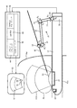
図1及び図2は、例示的な経会陰前立腺治療装置を図式的に示す。 1 and 2 schematically illustrate an exemplary transperineal prostate treatment device.
図1及び図2を参照すると、例示的な経会陰前立腺治療装置は、経会陰前立腺介入装置を含む。装置は、前立腺介入器具10と、超音波トランスデューサ又はトランスデューサアレイ14,15を備える経直腸超音波(TRUS)プローブ12を含む経会陰前立腺介入誘導装置とを含む。例示的なTRUSプローブ12は、矢状超音波トランスデューサアレイ14及び軸超音波トランスデューサアレイ15を含む。経会陰前立腺介入プロシージャの間、TRUSプローブ12は、前立腺介入を受ける患者の直腸Recに部分的に挿入され、TRUSプローブ12の挿入端部は、患者の直腸Recの内側に超音波トランスデューサ14,15を運び、患者の前立腺Prの少なくとも一部を交差し、又は含む視野(FOV)を有する超音波画像を生成するように超音波データを取得する位置に運ぶ。例示的な実施例は、FOV内のプレーナ輝度モード(Bモード)画像を取得するために矢状超音波トランスデューサアレイ14を使用するが、これは単なる例示であり、随意に選択される取得後処理を伴う他の超音波イメージングモードが、TRUSプローブ12を使用して収集される超音波データを使用して前立腺Prの超音波イメージングを行うために使用されてもよい。経会陰前立腺介入プロシージャは、介入器具10(の端部)による会陰Perの侵入を伴う。図1は、介入器具10による会陰Perの侵入前の装置を示す。図2は、介入器具10による会陰Perの侵入後の装置を示す。いくつかの非限定的な実施例によれば、経会陰前立腺介入プロシージャは、前立腺生検プロシージャであってもよく、その場合、介入器具10は生検針であり、又は経会陰前立腺介入プロシージャは、近接照射療法プロシージャであってもよく、その場合、介入器具10は近接照射療法シード送達器具であり、又は経会陰前立腺介入プロシージャは、組織切除プロシージャ(例えば、凍結切除、高周波切除など)であってもよく、その場合、介入器具10は、組織切除器具である。介入器具10はまた、上述した介入生検/治療器具(すなわち、生検針、近接照射療法針、切除針など)の一つ又はそれより多くを収容する中空カニューレであってもよい。
Referring to FIGS. 1 and 2, an exemplary transperineal prostate treatment device includes a transperineal prostate interventional device. The apparatus includes a prostate
経会陰前立腺介入誘導装置は、TRUSプローブ12の基準のフレーム内で介入器具20の位置及び方向を測定するための座標測定機(CMM)20をさらに含む。例示的なCMM20は、エンコーディングジョイント24、現在のジョイント角度を出力するセンサを備える回転ジョイントによって接続される複数のアームセグメント22(例えば、ロッド、ビーム、チューブなど)で構成される関節アームを有するポータブルCMMである。CMM20は、直腸Recの外側に延在するTRUSプローブ12の部分に固定される(すなわち、アンカーされる)べきクランプ又は他のマウントによって構成されるジョイント24(図示のように)又はアームセグメントに接続されるアンカー端部30を有する。CMM20はさらに、アームセグメント又はジョイント24に(図示のように)に接続され、前立腺介入器具10との取り付けのためのカラー又は他のマウントによって構成される、対向する可動端部32を有する。関節アームは、可動端部32の3次元的な自由度を提供するように設計されるが、アンカー端部30は、そのテザー点(図示の例ではTRUSプローブ12)に固定されたままである。図示されるように、各ジョイント24は、2つのエンコーディングされる角度調節方向、すなわち、2つの連結アームセグメント22の間の角度(又は連結アームセグメント22と連結端部30又は端部32との間の角度)が調節される、第1のエンコーディングされる角度調節方向R1と、一方のアームセグメント22又は端部32がその軸の周りに回転することができる第2の角度調節方向R2とを含む。これらは単なる例示的な関節であり、CMMの関節アームは、異なる数のジョイント、並びに各ジョイント又は異なるジョイントに対して異なる数又はタイプの運動を備える、他の関節アーキテクチャを有し得る。例えば、角度調節部R1及びR2に加えて、リンクが、図1に示される形状のロボットアームの平面に垂直な方向に移動することができる、第3の角度調節部R3が設けられることはできる。(すなわち、R3は、図1の「ページの内外」への動きを提供する。この第3の角度調節方向は、会陰/前立腺に対する横方向又は「L-R」方向の動きにほぼ対応する。)各エンコーディングされる動きは、関節アームに対して自由度を提供し、CMM20は、好ましくは少なくとも2つのジョイントを有し、図示の例では、3つのジョイント24を有し、介入器具10の柔軟な三次元運動を提供するのに十分ないくらかの自由度(3つのジョイント24の各々に対して図示されるCMM20-R1及びR2の6つの自由度)が提供される。非限定的な例によれば、CMM20として使用するのに適したポータブルCMMのいくつかには、Revware Systems、Raleigh、North Carolina、USAから入手可能なポータブルCMMシステムのMicroScribe(登録商標)ラインが含まれている。
The transperineal prostate intervention guide further includes a coordinate measuring machine (CMM) 20 for measuring the position and orientation of the
経会陰前立腺介入誘導装置は、例えば、マイクロプロセッサ又はマイクロコントローラを含む超音波イメージング装置とすることができる電子プロセッサ40をさらに含む。電子プロセッサ40は、超音波イメージング42オプションの3次元(3D)トラッキング44CMM位置(及び方向)デコーディング46及び軌道予測48を含む。これらの関数及びそれらの相互作用は、以下で説明される。
The transperineal prostate interventional guidance device further includes an
超音波イメージング42は、TRUSプローブ12を操作して、(随意にビデオを有する)前立腺Prの少なくとも一部の前立腺超音波画像50を生成する。前立腺超音波画像50は、ディスプレイコンポーネント52、例えばLCDディスプレイ、又は超音波イメージング装置の他のディスプレイコンポーネントに表示される。
オプションの3Dトラッキング装置44は、画像50のFOV内にあるとき、介入器具10の位置をトラッキングする。介入器具10の種類及び材料並びに実行される超音波イメージング42のタイプに依存して、いくつかの実施形態では、画像50のFOV内の介入器具10の部分は超音波画像内で可視であり、そのような場合、外科医は、前立腺超音波画像50のFOV内に延在する介入器具の部分を直接観察することができるため、3Dトラッキング44は実行される必要はなく、そのためこのコンポーネントはオプションである。たとえ介入器具が画像内で観察できないとしても、その位置は、後述するようにCMM位置デコーディング46によって決定されることができるので、3Dトラッキング44はここでもオプションである。一方、CMMを使用して挿入される介入器具をトラッキングすることは、介入器具が会陰を通過して前立腺に入るときに直線状であることを前提として動作するので、問題となり得る。CMMベースのトラッキングは、器具のいかなる屈曲も検出しないが、3Dトラッキングは、画像50のFOVにおけるそのような屈曲を検出することができる。提供される場合、3Dトラッキング44は、TRUSプローブ12によって出力される超音波送信に応答して生成される超音波信号を使用して前立腺超音波画像50のFOV内に前立腺介入器具10の部分の位置及び方向を決定する。1つのアプローチでは、これらの超音波信号は前立腺超音波画像であり、介入器具の位置を決定するようにセグメント化されることができる。他の実施形態では、これらの信号は、TRUSプローブによって出力される超音波送信に応答して前立腺介入器具10に配置される超音波センサ(図示略)によって生成されてもよい。このような3Dツールトラッキングは、例えば、Mungらの、「超音波誘導介入のためのロバスト3Dツールトラッキングのための非破壊技術」(MICCAI 2011、パートI、LNCS 6891、pp.153-160(2011))に記載される。
An optional
CMM位置デコーディング46は、ジョイント22のエンコーディングされる角度位置R1、R2から決定されるCMM20の可動端部32の位置及び方向から介入器具10の位置及び方向を決定する。CMM20がMicroScribe(登録商標)のような商品である場合、可動端部32の位置及び方向は、CMM20用の市販の制御ソフトウェアによって報告されてもよい。より一般的には、位置及び方向は、アンカー端部30の既知の固定位置で開始し、接続ジョイント24の角度位置(又はより一般的にはエンコーディング値)に基づいて次のアームセグメント22の位置及び方向を決定することによって計算されることができ、最後の動作が、最後の接続ジョイント24のエンコーディング値に基づいて可動端部32の位置及び方向を決定するまで、このように1つのアームセグメントから次のアームセグメントまで継続される。この処理は、CMM20の可動端部32の位置及び方向を提供し、介入器具10の位置及び方向はそれから、それが可動端部32に固定され、したがって可動端部32に対する固定位置及び方向を有するため推測されることができる。すべての処理は、TRUSプローブ12に固定されるCMM20のアンカー端部30に対して参照されるので、結果としてもたらされる介入器具10のCMM決定位置及び方向は、TRUSプローブ12の基準のフレーム内にある。
The CMM position decoding 46 determines the position and direction of the
アームセグメント22及びエンコーディングジョイント24を有する関節アームを使用する例示的なCMM20は例示的な例である。TRUSプローブ12に固定されることができる他のタイプのCMMは、代わりに使用されることができる。他の例示的な例として、CMMは、異なる角度の範囲(典型的には少なくとも3つの異なる角度が必要とされる)から介入器具10の先端を光学的に見るように構成されるカメラ又は他の光学センサのセットを有する光学CMMであってもよい。この場合、CMM位置デコーディング46は、3次元三角測量を適切に使用して、異なる視点から介入器具10の位置及び方向を決定する。光学CMMの利点は、アームが介入器具10と物理的に接続されていないことにある。不利な点は、器具10を操作する外科医の手が、光学CMMの一つ又はそれより多くの光センサの視界を遮る場合、これはCMM位置デコーディング46の動作を中断し得ることにある。
An
異なる考えられる変形例として、図示のような関節アームを含むCMM20が使用されることができるが、ジョイント24は、関節アームがロボットアームになるようにモータ作動される。この場合、外科医は、ロボットアームを使用して、介入器具10を操作することができ、例えば、ジョイスティックを用いてそれを制御することができる。
As a different possible variant, a
介入器具10の位置及び方向がCMM位置デコーディング46によって決定された後、軌道予測部48はそれから、前立腺Prにおける介入器具10の軌道54(図1参照)を予測するように動作する。典型的には、会陰Perを通って前立腺Prに侵入するように設計される介入器具10の端部は直線状であり、例えば、真っ直ぐな生検針、又は近接照射療法シード送達器具の操作端部を規定する真っ直ぐな中空管、又はRF切除エミッタ又は低温先端部で終端する真っ直ぐな針を有する組織生検器具などである。直線端部は最小限の損傷で組織への挿入を容易にする。したがって、軌道予測部48は、前立腺Prを含む既知の空間ボリュームに交差するまで、介入器具10の直線端部の既知の位置及び方向の直線的な延在を計算することにより動作する。この後者は、前立腺超音波画像50の基準のフレームでもあるTRUSプローブ12の基準のフレーム内にある介入機器10のCMM決定される位置及び方向を利用して前立腺超音波画像50から決定される。
After the position and orientation of the
軌道予測部48は、図1に示すように、介入器具10が会陰Perを貫通する前であっても、介入器具10の予測軌道54を計算するように動作することは留意される。好ましいワークフローにおいて、外科医は、介入器具の位置を安定させるために、図1に示すように、会陰Perに対して介入器具10の先端を押し付ける。超音波イメージング42は、予測軌道54を受信し、それを重畳予測軌道表現56として前立腺超音波画像50に重畳する。このようにして、外科医は、介入器具10の予測軌道54を視覚的に知らされ、軌道が受け入れられない場合、彼又は彼女は、介入器具10を再配置することができ、前立腺超音波画像50上のその重畳表示56によって表される予測軌道54が外科医にとって満足できるものになるまで、プロセスを繰り返すことができる。
It is noted that the
図2を参照すると、外科医が予測軌道54に満足した後、彼又は彼女は、会陰Perを通って前立腺Prに侵入させるために、介入器具10を会陰Perに押し込むことによって、焦点前立腺介入を進めることができる。この動作の正確な機構は、介入器具10及びCMM20の可動端部32の構成に依存する。例えば、いくつかのタイプの介入器具では、器具は同軸の内側及び外側の管状コンポーネントを含み、内側管状コンポーネントは、内側管状コンポーネントから延在して、会陰Per及びそれから前立腺Prに侵入する。この場合、CMM20の可動端部32のスリーブ又は他のマウントは、介入器具10の外側管状コンポーネントに堅固に固定されることができる。他のタイプの介入器具では、器具の直線端部全体が一つのユニットとして移動され、これらの実施形態では、CMM20の可動端部32は、介入器具の直線端部の周りにおいてずっと又は途中で固定されるスリーブとして構成されることができ、介入器具は、介入器具の先端が会陰Perを通って前立腺Prに侵入する介入を行うために、スリーブを通じて軸方向に摺動することができる。図2に示すように、これが起こるとき、前立腺介入器具10の端部は前立腺超音波画像50のFOVに入り、図示の実施形態では先端画像58として視認可能である。随意的に、軌道予測58は、CMM位置デコーディング46に基づいて動作し続けて、画像内に予測軌道54及びその表現56を生成する。代替的に、その点で、外科医は、可視先端画像58によって誘導され得るため、予測軌道は、前立腺超音波画像50のFOVに入る前立腺介入器具10の端部に応じて終了することができる。
Referring to FIG. 2, after the surgeon is satisfied with the predicted
オプションの3Dトラッキング44が提供される場合、前立腺超音波画像50のFOVに入った介入器具10の部分は、CMM位置デコーディング46を使用して決定される予測軌道56に頼る代わりに、3Dトラッキング44のみによってトラッキングされることができる。この場合の他の選択肢として、介入器具の先端部及び/又はシャフトは、3Dトラッキング部44によって示される介入器具の位置及び方向と、CMM位置デコーディング46を使用して決定される予測軌道56との加重組合せとしてトラッキングされることができる。このアプローチは、これらのトラッキングモダリティのうちの1つが誤った結果を生成する場合に有利な冗長性を提供する。いくつかのこのような冗長なトラッキングの実施形態では、2つのトラッキング方法が、閾値の量より多く異なる結果を提供する場合、視覚的及び/又は音響的アラームが起動されて、トラッキングは信頼できないこと、又はこの不一致を引き起こしている針屈曲が起こったことを外科医に警告する。
If the optional 3D tracking 44 is provided, the portion of the
図3を参照すると、図1及び2を参照して説明した例示的な装置を使用して実施される焦点前立腺介入は、TRUSプローブ12が患者の直腸Recに挿入される操作70で始まる。操作72において、CMM20のアンカー端部30は、直腸Recの外側に延在するTRUSプローブ12の部分に取り付けられる。(代わりに、CMMは、TRUSプローブが直腸に挿入される前に取り付けられることができる)。操作74において、介入器具10は、CMM20の可動端部32に取り付けられる。この時点で、誘導装置がセットアップされ、(好ましくはビデオ)超音波イメージングが開始される。操作80において、介入器具10は、標的(例えば、疑わしい又は既知の癌性腫瘍又は前立腺Prの領域)と位置合わせされる。この位置合わせ80は、予測軌道54を使用して、より詳細には、前立腺超音波画像50に重ね合わされるこの軌道の表示56を視覚的に観察することによって行われる。外科医が器具位置合わせに満足すると、手術82において、外科医は、TRUSプローブ12によって提供される超音波イメージング及び/又はCMM20によって提供される予測軌道54、又はこれら2つの重み付けされる組み合わせを使用して、介入プロセスをトラッキングしながら、会陰Perを介して前立腺Prに介入器具を挿入させる。操作84では、挿入される介入器具10を使用して前立腺介入が行われる。これは、例えば、生検試料の取得、放射性近接照射療法シードの蓄積、RFアブレーション又は凍結切除の実施などを伴う。随意に、前述のプロセスは、前立腺の複数の標的領域に対する介入を実施するために繰り返されてもよい。そのような場合、操作70,72は概して繰り返される必要はなく、操作74は、介入器具10の再使用可能性に依存して繰り返されてもよいし、繰り返されなくてもよい。
Referring to FIG. 3, the focal prostate intervention performed using the exemplary apparatus described with reference to FIGS. 1 and 2 begins with
本発明を好ましい実施形態を参照して説明した。前述の詳細な説明を読んで理解すると、他の人に修正や変更が行われることがある。本発明は、添付の特許請求の範囲又はその等価物の範囲内に入る限りにおいて、そのような改変及び変更の全てを有すると解釈されることが意図される。 The invention has been described with reference to the preferred embodiments. Upon reading and understanding the above detailed description, modifications and changes may be made to others. The present invention is intended to be construed as having all such modifications and variations as long as they fall within the scope of the appended claims or their equivalents.
Claims (20)
超音波トランスデューサ又はトランスデューサアレイを含む経直腸超音波プローブと、
前記経会陰超音波プローブへの取り付けのために構成され、前記経会陰超音波プローブの基準のフレームにおいて前記前立腺介入器具の位置及び方向をトラッキングするように構成される座標測定機と、
電子プロセッサであって、
前記座標測定機を使用して前記経会陰超音波プローブの基準のフレームにおける前記前立腺介入器具の予測軌道を計算し、
前記前立腺超音波画像に重ね合わされる前記前立腺介入器具の前記予測軌道の表現と共に前記経会陰超音波プローブによって収集される超音波データから前記前立腺超音波画像を生成する
ようにプログラムされる、電子プロセッサと
を有する、経会陰前立腺介入誘導装置。 A transperineal prostate intervention device,
A transrectal ultrasound probe comprising an ultrasound transducer or transducer array;
A coordinate measuring machine configured for attachment to the transperineal ultrasound probe and configured to track the position and orientation of the prostate interventional instrument in a reference frame of the transperineal ultrasound probe;
An electronic processor,
Calculating a predicted trajectory of the prostate interventional instrument in the reference frame of the transperineal ultrasound probe using the coordinate measuring machine;
Electronic programmed to generate the prostate ultrasound image from ultrasound data collected by the transperineal ultrasound probe along with a representation of the predicted trajectory of the prostate interventional instrument superimposed on the prostate ultrasound image A transperineal prostate interventional guidance device having a processor.
前記電子プロセッサは、前記エンコーディングジョイントのエンコーディング値から決定される前記関節アームの前記可動端部の位置及び方向から前記予測軌道を計算するようにプログラムされる、
請求項1に記載の経会陰前立腺介入誘導装置。 The coordinate measuring machine includes an arm segment connected by an encoding joint and is configured for attachment to an anchor end configured for attachment to the transperineal ultrasound probe and the prostate interventional instrument Having a joint arm with a movable end;
The electronic processor is programmed to calculate the predicted trajectory from the position and orientation of the movable end of the articulated arm determined from the encoding value of the encoding joint.
The transperineal prostate intervention guidance device according to claim 1.
前記経会陰超音波プローブによって出力される超音波送信に応答して生成される超音波信号を使用して、前記前立腺超音波画像の視野における前記前立腺介入器具の部分の位置及び方向を決定する
ように更にプログラムされる、請求項1乃至2の何れか一項に記載の経会陰前立腺介入誘導装置。 The electronic processor is
An ultrasound signal generated in response to an ultrasound transmission output by the transperineal ultrasound probe is used to determine the position and orientation of the portion of the prostate interventional instrument in the field of view of the prostate ultrasound image The transperineal prostate interventional guidance device according to any one of claims 1 to 2, further programmed as follows.
ように更にプログラムされる、請求項3に記載の経会陰前立腺介入誘導装置。 The electronic processor is generated by an ultrasonic sensor disposed in the prostate interventional instrument in response to (i) the prostate ultrasound image and (ii) an ultrasound transmission output by the transperineal ultrasound probe 4. The meeting of claim 3, further programmed to determine a position and orientation of a portion of the prostate interventional instrument in a field of view of the prostate ultrasound image using an ultrasound signal having one of the signals. Yin prostate intervention guidance device.
ようにプログラムされる、請求項4に記載の経会陰前立腺介入誘導装置。 The electronic processor is programmed to further use the predicted trajectory of the prostate interventional instrument to determine the position and orientation of a portion of the prostate interventional instrument in the field of view of the prostate ultrasound image. The transperineal prostate intervention guide device described.
(1)前記経会陰超音波プローブによって出力される前記超音波送信に応答して生成される前記超音波信号を使用して決定される、前記前立腺超音波画像の前記視野における前記前立腺介入器具の前記部分の超音波ベースの位置及び方向、及び
(2)前記前立腺介入器具の前記予測軌道
の加重組合せとして、前記前立腺超音波画像の前記視野における前記前立腺介入器具の前記部分の位置及び方向を決定するようにプログラムされる、請求項5に記載の経会陰前立腺介入誘導装置。 The electronic processor is
(1) The prostate intervention device in the field of view of the prostate ultrasound image determined using the ultrasound signal generated in response to the ultrasound transmission output by the transperineal ultrasound probe The location and orientation of the ultrasound base of said portion of
(2) programmed to determine the position and orientation of the portion of the prostate interventional instrument in the field of view of the prostate ultrasound image as a weighted combination of the predicted trajectories of the prostate interventional instrument. Transperineal prostate interventional guidance device.
前記座標測定機の前記可動端部への取り付けのために構成され、会陰の貫通を介した前立腺への侵入のために構成される端部を有する、前立腺介入器具と
を有する、経会陰前立腺介入装置。 The transperineal prostate interventional guidance device according to any one of claims 1 to 6, wherein the coordinate measuring machine includes an arm segment connected by an encoding joint, A transperineal prostate interventional guidance device having an articulated arm having an anchor end configured for attachment and a movable end configured for attachment with the prostate interventional instrument;
A transperineum having a prostate interventional instrument configured for attachment to the movable end of the coordinate measuring machine and having an end configured for penetration into the prostate via a perineal penetration Prostate intervention device.
前立腺介入器具と、
超音波トランスデューサ又はトランスデューサアレイを含む経直腸超音波プローブと、
前記経直腸超音波プローブに取り付けられ、前記前立腺介入器具をトラッキングするように構成される機械式又は光学式座標測定機と
を有する、経会陰前立腺介入装置。 A transperineal prostate intervention device,
A prostate intervention device,
A transrectal ultrasound probe comprising an ultrasound transducer or transducer array;
A transperineal prostate interventional device attached to the transrectal ultrasound probe and having a mechanical or optical coordinate measuring machine configured to track the prostate interventional instrument.
を有する、請求項9に記載の経会陰前立腺介入装置。 The mechanical or optical coordinate measuring machine is attached to the prostate interventional instrument, a mechanical coordinate measuring machine including an articulated arm with a plurality of encoding joints, an anchor end attached to the transperineal ultrasound probe, and The transperineal prostate interventional device of claim 9 having a movable end.
を更に有する、請求項9乃至12の何れか一項に記載の経会陰前立腺介入装置。 Programmed to calculate the predicted trajectory of the prostate interventional instrument in the reference frame of the transperineal ultrasound probe using the mechanical or optical coordinate measuring machine attached to the transperineal ultrasound probe 13. The transperineal prostate interventional device according to any one of claims 9 to 12, further comprising an electronic processor.
前記電子プロセッサは、表示される前記前立腺超音波画像に重ね合わされる前記前立腺介入器具の前記予測軌道の表現と共に前記経会陰超音波プローブによって収集される超音波データから生成される前立腺超音波画像を前記ディスプレイコンポーネントに表示させるように更にプログラムされる、請求項13に記載の経会陰前立腺介入装置。 A display component;
The electronic processor generates a prostate ultrasound image generated from ultrasound data collected by the transperineal ultrasound probe along with a representation of the predicted trajectory of the prostate interventional instrument superimposed on the displayed prostate ultrasound image 14. The transperineal prostate intervention device of claim 13, further programmed to cause the display component to display.
経直腸超音波プローブによって取得される超音波データから生成される前立腺の超音波画像を表示するステップと、
前記表示するステップの間、前記経会陰超音波プローブに固定される機械式又は光学式座標測定機を使用して前記経会陰超音波プローブの基準のフレームにおける前立腺介入器具の予測軌道を計算するステップと、
前記前立腺の表示される前記超音波画像に前記前立腺介入器具の前記予測軌道の表示を重ね合わせるステップと
を有する、経会陰前立腺介入誘導方法。 A transperineal prostate intervention induction method,
Displaying an ultrasound image of the prostate generated from ultrasound data acquired by a transrectal ultrasound probe;
During the displaying step, a predicted trajectory of the prostate interventional instrument in the reference frame of the transperineal ultrasound probe is calculated using a mechanical or optical coordinate measuring machine fixed to the transperineal ultrasound probe And steps to
Superimposing a display of the predicted trajectory of the prostate intervention instrument on the displayed ultrasound image of the prostate.
Priority Applications (1)
| Application Number | Priority Date | Filing Date | Title |
|---|---|---|---|
| JP2022012153A JP2022058793A (en) | 2015-12-04 | 2022-01-28 | System and workflow for grid-less transperineal prostate syndrome |
Applications Claiming Priority (3)
| Application Number | Priority Date | Filing Date | Title |
|---|---|---|---|
| US201562263160P | 2015-12-04 | 2015-12-04 | |
| US62/263,160 | 2015-12-04 | ||
| PCT/IB2016/057174 WO2017093885A1 (en) | 2015-12-04 | 2016-11-29 | System and workflow for grid-less transperineal prostate interventions |
Related Child Applications (1)
| Application Number | Title | Priority Date | Filing Date |
|---|---|---|---|
| JP2022012153A Division JP2022058793A (en) | 2015-12-04 | 2022-01-28 | System and workflow for grid-less transperineal prostate syndrome |
Publications (2)
| Publication Number | Publication Date |
|---|---|
| JP2019502432A true JP2019502432A (en) | 2019-01-31 |
| JP2019502432A5 JP2019502432A5 (en) | 2020-01-09 |
Family
ID=57539572
Family Applications (2)
| Application Number | Title | Priority Date | Filing Date |
|---|---|---|---|
| JP2018526913A Pending JP2019502432A (en) | 2015-12-04 | 2016-11-29 | System and workflow for gridless transperineal prostate syndrome |
| JP2022012153A Pending JP2022058793A (en) | 2015-12-04 | 2022-01-28 | System and workflow for grid-less transperineal prostate syndrome |
Family Applications After (1)
| Application Number | Title | Priority Date | Filing Date |
|---|---|---|---|
| JP2022012153A Pending JP2022058793A (en) | 2015-12-04 | 2022-01-28 | System and workflow for grid-less transperineal prostate syndrome |
Country Status (5)
| Country | Link |
|---|---|
| US (1) | US11096745B2 (en) |
| EP (1) | EP3383305A1 (en) |
| JP (2) | JP2019502432A (en) |
| CN (1) | CN108289714B (en) |
| WO (1) | WO2017093885A1 (en) |
Families Citing this family (7)
| Publication number | Priority date | Publication date | Assignee | Title |
|---|---|---|---|---|
| EP3492018A1 (en) * | 2017-11-30 | 2019-06-05 | Koninklijke Philips N.V. | Device and method for providing information about a biopsy taking process and biopsy system |
| US11638569B2 (en) | 2018-06-08 | 2023-05-02 | Rutgers, The State University Of New Jersey | Computer vision systems and methods for real-time needle detection, enhancement and localization in ultrasound |
| EP3836843A4 (en) * | 2018-08-13 | 2022-02-16 | Rutgers, the State University of New Jersey | Computer vision systems and methods for real-time localization of needles in ultrasound images |
| EP3937792A1 (en) * | 2019-03-12 | 2022-01-19 | B-K Medical ApS | Ultrasound-guided transperineal and/or transrectal biopsy |
| WO2023110598A1 (en) * | 2021-12-16 | 2023-06-22 | Koninklijke Philips N.V. | System and method for estimating and visualizing trajectories of robotically controlled interventional device |
| EP4197476A1 (en) * | 2021-12-16 | 2023-06-21 | Koninklijke Philips N.V. | System and method for estimating and visualizing trajectories of robotically controlled interventional device |
| TWI798040B (en) * | 2022-03-30 | 2023-04-01 | 國立成功大學 | Needle guidance device |
Citations (8)
| Publication number | Priority date | Publication date | Assignee | Title |
|---|---|---|---|---|
| US5647373A (en) * | 1993-11-07 | 1997-07-15 | Ultra-Guide Ltd. | Articulated needle guide for ultrasound imaging and method of using same |
| US20020156376A1 (en) * | 2001-03-16 | 2002-10-24 | U-Systems, Inc. | Guide and position monitor for invasive medical instrument |
| JP2002541947A (en) * | 1999-04-15 | 2002-12-10 | ウルトラガイド・リミテッド | Apparatus and method for detecting bending of medical invasive device during medical procedure |
| US20090030339A1 (en) * | 2006-01-26 | 2009-01-29 | Cheng Wai Sam C | Apparatus and method for motorised placement of needle |
| US20090198094A1 (en) * | 2004-03-09 | 2009-08-06 | Robarts Research Institute | Apparatus and computing device for performing brachytherapy and methods of imaging using the same |
| US20090234369A1 (en) * | 2006-06-19 | 2009-09-17 | Robarts Research Institute | Apparatus for guiding a medical tool |
| JP2013525057A (en) * | 2010-05-03 | 2013-06-20 | コーニンクレッカ フィリップス エレクトロニクス エヌ ヴィ | Ultrasonic tracking of ultrasonic transducers mounted on interventional instruments |
| US20150065886A1 (en) * | 2012-04-10 | 2015-03-05 | Trhe Johns Hopkins University | Cohesive robot-ultrasound probe for prostate biopsy |
Family Cites Families (14)
| Publication number | Priority date | Publication date | Assignee | Title |
|---|---|---|---|---|
| EP1440708B1 (en) | 2003-01-27 | 2006-12-06 | Nucletron B.V. | Device for image guided automated insertion of an elongated hollow needle for brachytherapy |
| CN101578073A (en) * | 2006-01-09 | 2009-11-11 | 拜奥斯皮罗有限公司 | System and method for thermally treating tissues |
| US7950299B2 (en) | 2006-02-21 | 2011-05-31 | Rainer Burgkart | Adjusting and guiding system for tools |
| CA2646363C (en) * | 2006-03-14 | 2015-07-21 | The Johns Hopkins University | Apparatus for insertion of a medical device within a body during a medical imaging process and devices and methods related thereto |
| US8374673B2 (en) * | 2007-01-25 | 2013-02-12 | Warsaw Orthopedic, Inc. | Integrated surgical navigational and neuromonitoring system having automated surgical assistance and control |
| ES2398869T3 (en) | 2009-04-01 | 2013-03-22 | Nucletron Operations B.V. | Components and assembly to perform brachytherapy treatment of tumor tissue in a human or animal body |
| US9521994B2 (en) * | 2009-05-11 | 2016-12-20 | Siemens Healthcare Gmbh | System and method for image guided prostate cancer needle biopsy |
| US8556815B2 (en) * | 2009-05-20 | 2013-10-15 | Laurent Pelissier | Freehand ultrasound imaging systems and methods for guiding fine elongate instruments |
| JP5863654B2 (en) | 2009-08-26 | 2016-02-16 | リージェンツ オブ ザ ユニバーシティー オブ ミシガン | Micromanipulator control arm for therapeutic and image processing ultrasonic transducers |
| US20110071380A1 (en) * | 2009-09-09 | 2011-03-24 | Goldenberg Andrew A | Manual Instrumented Medical Tool System |
| JP6021484B2 (en) * | 2011-08-04 | 2016-11-09 | オリンパス株式会社 | Medical manipulator |
| CA2861654A1 (en) | 2012-01-06 | 2013-07-11 | Histosonics, Inc. | Histotripsy therapy transducer |
| FR2991160B1 (en) * | 2012-06-01 | 2015-05-15 | Koelis | MEDICAL IMAGING PROBE GUIDING DEVICE, MEDICAL IMAGING PROBE ADAPTED TO BE GUIDED BY SUCH A DEVICE, AND METHOD FOR GUIDING SUCH PROBE. |
| CN104602626B (en) * | 2012-08-28 | 2018-03-02 | 皇家飞利浦有限公司 | The intervention set with integrated tracking guides system |
-
2016
- 2016-11-29 CN CN201680070940.5A patent/CN108289714B/en active Active
- 2016-11-29 WO PCT/IB2016/057174 patent/WO2017093885A1/en active Application Filing
- 2016-11-29 JP JP2018526913A patent/JP2019502432A/en active Pending
- 2016-11-29 EP EP16809531.3A patent/EP3383305A1/en not_active Withdrawn
- 2016-11-29 US US15/776,921 patent/US11096745B2/en active Active
-
2022
- 2022-01-28 JP JP2022012153A patent/JP2022058793A/en active Pending
Patent Citations (8)
| Publication number | Priority date | Publication date | Assignee | Title |
|---|---|---|---|---|
| US5647373A (en) * | 1993-11-07 | 1997-07-15 | Ultra-Guide Ltd. | Articulated needle guide for ultrasound imaging and method of using same |
| JP2002541947A (en) * | 1999-04-15 | 2002-12-10 | ウルトラガイド・リミテッド | Apparatus and method for detecting bending of medical invasive device during medical procedure |
| US20020156376A1 (en) * | 2001-03-16 | 2002-10-24 | U-Systems, Inc. | Guide and position monitor for invasive medical instrument |
| US20090198094A1 (en) * | 2004-03-09 | 2009-08-06 | Robarts Research Institute | Apparatus and computing device for performing brachytherapy and methods of imaging using the same |
| US20090030339A1 (en) * | 2006-01-26 | 2009-01-29 | Cheng Wai Sam C | Apparatus and method for motorised placement of needle |
| US20090234369A1 (en) * | 2006-06-19 | 2009-09-17 | Robarts Research Institute | Apparatus for guiding a medical tool |
| JP2013525057A (en) * | 2010-05-03 | 2013-06-20 | コーニンクレッカ フィリップス エレクトロニクス エヌ ヴィ | Ultrasonic tracking of ultrasonic transducers mounted on interventional instruments |
| US20150065886A1 (en) * | 2012-04-10 | 2015-03-05 | Trhe Johns Hopkins University | Cohesive robot-ultrasound probe for prostate biopsy |
Also Published As
| Publication number | Publication date |
|---|---|
| WO2017093885A1 (en) | 2017-06-08 |
| US11096745B2 (en) | 2021-08-24 |
| CN108289714A (en) | 2018-07-17 |
| JP2022058793A (en) | 2022-04-12 |
| CN108289714B (en) | 2021-06-18 |
| US20180325602A1 (en) | 2018-11-15 |
| EP3383305A1 (en) | 2018-10-10 |
Similar Documents
| Publication | Publication Date | Title |
|---|---|---|
| US11096745B2 (en) | System and workflow for grid-less transperineal prostate interventions | |
| JP4455995B2 (en) | Medical device positioning system and method | |
| US6678546B2 (en) | Medical instrument guidance using stereo radiolocation | |
| EP2769689B1 (en) | Computer-implemented technique for calculating a position of a surgical device | |
| RU2464931C2 (en) | Device for determining position of first object inside second object | |
| US9237929B2 (en) | System for guiding a medical instrument in a patient body | |
| US20070021744A1 (en) | Apparatus and method for performing ablation with imaging feedback | |
| JP2009531113A (en) | Image guided surgery system | |
| US20080234570A1 (en) | System For Guiding a Medical Instrument in a Patient Body | |
| EP3047809B1 (en) | Extracorporeal shock wave lithotripsy system having off-line ultrasound localization | |
| JP2001061861A (en) | System having image photographing means and medical work station | |
| JP7171948B2 (en) | Ultrasound system and method for tracking movement of an object | |
| US11071518B2 (en) | Imaging apparatus for biopsy or brachytherapy | |
| JP2011189117A (en) | Method and apparatus for locating and visualizing target in relation to focal point of treatment system | |
| CN113367795A (en) | Ureteroscope soft lens with magnetic positioning function and ureteroscope pose estimation system | |
| JP2006263068A (en) | Ultrasonic diagnostic apparatus | |
| Nguyen et al. | Percutaneous nephrolithotomy access: A systematic review of intraoperative assistive technologies | |
| JP2020058779A (en) | Method for supporting user, computer program product, data storage medium, and imaging system | |
| CN216439306U (en) | Ureteroscope soft lens with magnetic positioning function and ureteroscope pose estimation system |
Legal Events
| Date | Code | Title | Description |
|---|---|---|---|
| A521 | Request for written amendment filed |
Free format text: JAPANESE INTERMEDIATE CODE: A523 Effective date: 20191122 |
|
| A621 | Written request for application examination |
Free format text: JAPANESE INTERMEDIATE CODE: A621 Effective date: 20191122 |
|
| A977 | Report on retrieval |
Free format text: JAPANESE INTERMEDIATE CODE: A971007 Effective date: 20201116 |
|
| A131 | Notification of reasons for refusal |
Free format text: JAPANESE INTERMEDIATE CODE: A131 Effective date: 20201124 |
|
| A601 | Written request for extension of time |
Free format text: JAPANESE INTERMEDIATE CODE: A601 Effective date: 20210218 |
|
| A521 | Request for written amendment filed |
Free format text: JAPANESE INTERMEDIATE CODE: A523 Effective date: 20210524 |
|
| A02 | Decision of refusal |
Free format text: JAPANESE INTERMEDIATE CODE: A02 Effective date: 20210930 |
|
| A521 | Request for written amendment filed |
Free format text: JAPANESE INTERMEDIATE CODE: A523 Effective date: 20220128 |
|
| C60 | Trial request (containing other claim documents, opposition documents) |
Free format text: JAPANESE INTERMEDIATE CODE: C60 Effective date: 20220128 |
|
| A911 | Transfer to examiner for re-examination before appeal (zenchi) |
Free format text: JAPANESE INTERMEDIATE CODE: A911 Effective date: 20220204 |
|
| C21 | Notice of transfer of a case for reconsideration by examiners before appeal proceedings |
Free format text: JAPANESE INTERMEDIATE CODE: C21 Effective date: 20220208 |
|
| A912 | Re-examination (zenchi) completed and case transferred to appeal board |
Free format text: JAPANESE INTERMEDIATE CODE: A912 Effective date: 20220401 |
|
| C211 | Notice of termination of reconsideration by examiners before appeal proceedings |
Free format text: JAPANESE INTERMEDIATE CODE: C211 Effective date: 20220405 |
|
| C22 | Notice of designation (change) of administrative judge |
Free format text: JAPANESE INTERMEDIATE CODE: C22 Effective date: 20220531 |
|
| C13 | Notice of reasons for refusal |
Free format text: JAPANESE INTERMEDIATE CODE: C13 Effective date: 20220714 |
|
| A601 | Written request for extension of time |
Free format text: JAPANESE INTERMEDIATE CODE: A601 Effective date: 20220912 |
|
| A521 | Request for written amendment filed |
Free format text: JAPANESE INTERMEDIATE CODE: A523 Effective date: 20221128 |
|
| C13 | Notice of reasons for refusal |
Free format text: JAPANESE INTERMEDIATE CODE: C13 Effective date: 20230302 |