JP4455995B2 - Medical device positioning system and method - Google Patents
Medical device positioning system and method Download PDFInfo
- Publication number
- JP4455995B2 JP4455995B2 JP2004527564A JP2004527564A JP4455995B2 JP 4455995 B2 JP4455995 B2 JP 4455995B2 JP 2004527564 A JP2004527564 A JP 2004527564A JP 2004527564 A JP2004527564 A JP 2004527564A JP 4455995 B2 JP4455995 B2 JP 4455995B2
- Authority
- JP
- Japan
- Prior art keywords
- medical device
- medical
- subject
- tracking
- interest
- Prior art date
- Legal status (The legal status is an assumption and is not a legal conclusion. Google has not performed a legal analysis and makes no representation as to the accuracy of the status listed.)
- Expired - Fee Related
Links
- 238000000034 method Methods 0.000 title claims description 29
- 238000003384 imaging method Methods 0.000 claims description 29
- 238000012544 monitoring process Methods 0.000 claims description 29
- 238000001574 biopsy Methods 0.000 claims description 17
- 238000012545 processing Methods 0.000 claims description 10
- 230000004044 response Effects 0.000 claims description 10
- 238000002591 computed tomography Methods 0.000 claims description 8
- 238000002595 magnetic resonance imaging Methods 0.000 claims description 7
- 230000000007 visual effect Effects 0.000 claims description 7
- 238000002059 diagnostic imaging Methods 0.000 claims description 6
- 230000003213 activating effect Effects 0.000 claims description 4
- 230000001225 therapeutic effect Effects 0.000 claims description 4
- 238000002600 positron emission tomography Methods 0.000 claims description 3
- 239000000523 sample Substances 0.000 claims description 3
- 238000002604 ultrasonography Methods 0.000 claims description 3
- 238000002679 ablation Methods 0.000 claims description 2
- 238000001514 detection method Methods 0.000 description 8
- 230000005284 excitation Effects 0.000 description 4
- 238000002560 therapeutic procedure Methods 0.000 description 4
- 230000008859 change Effects 0.000 description 3
- 238000011282 treatment Methods 0.000 description 3
- 238000002405 diagnostic procedure Methods 0.000 description 2
- 238000010586 diagram Methods 0.000 description 2
- 238000007689 inspection Methods 0.000 description 2
- 230000002452 interceptive effect Effects 0.000 description 2
- 238000013152 interventional procedure Methods 0.000 description 2
- 238000005259 measurement Methods 0.000 description 2
- 210000002307 prostate Anatomy 0.000 description 2
- 238000001356 surgical procedure Methods 0.000 description 2
- 239000011149 active material Substances 0.000 description 1
- 210000003484 anatomy Anatomy 0.000 description 1
- 230000001186 cumulative effect Effects 0.000 description 1
- 230000000694 effects Effects 0.000 description 1
- 150000002222 fluorine compounds Chemical class 0.000 description 1
- 238000013532 laser treatment Methods 0.000 description 1
- 238000000691 measurement method Methods 0.000 description 1
- 238000012986 modification Methods 0.000 description 1
- 230000004048 modification Effects 0.000 description 1
- 238000001208 nuclear magnetic resonance pulse sequence Methods 0.000 description 1
- 230000008569 process Effects 0.000 description 1
- 230000005855 radiation Effects 0.000 description 1
- 230000003068 static effect Effects 0.000 description 1
- 238000006467 substitution reaction Methods 0.000 description 1
- 239000013589 supplement Substances 0.000 description 1
- 238000009210 therapy by ultrasound Methods 0.000 description 1
- 210000001519 tissue Anatomy 0.000 description 1
Images

Classifications
-
- A—HUMAN NECESSITIES
- A61—MEDICAL OR VETERINARY SCIENCE; HYGIENE
- A61B—DIAGNOSIS; SURGERY; IDENTIFICATION
- A61B34/00—Computer-aided surgery; Manipulators or robots specially adapted for use in surgery
- A61B34/20—Surgical navigation systems; Devices for tracking or guiding surgical instruments, e.g. for frameless stereotaxis
-
- A—HUMAN NECESSITIES
- A61—MEDICAL OR VETERINARY SCIENCE; HYGIENE
- A61B—DIAGNOSIS; SURGERY; IDENTIFICATION
- A61B34/00—Computer-aided surgery; Manipulators or robots specially adapted for use in surgery
- A61B34/10—Computer-aided planning, simulation or modelling of surgical operations
- A61B2034/101—Computer-aided simulation of surgical operations
- A61B2034/102—Modelling of surgical devices, implants or prosthesis
-
- A—HUMAN NECESSITIES
- A61—MEDICAL OR VETERINARY SCIENCE; HYGIENE
- A61B—DIAGNOSIS; SURGERY; IDENTIFICATION
- A61B34/00—Computer-aided surgery; Manipulators or robots specially adapted for use in surgery
- A61B34/10—Computer-aided planning, simulation or modelling of surgical operations
- A61B2034/107—Visualisation of planned trajectories or target regions
-
- A—HUMAN NECESSITIES
- A61—MEDICAL OR VETERINARY SCIENCE; HYGIENE
- A61B—DIAGNOSIS; SURGERY; IDENTIFICATION
- A61B34/00—Computer-aided surgery; Manipulators or robots specially adapted for use in surgery
- A61B34/20—Surgical navigation systems; Devices for tracking or guiding surgical instruments, e.g. for frameless stereotaxis
- A61B2034/2046—Tracking techniques
- A61B2034/2051—Electromagnetic tracking systems
-
- A—HUMAN NECESSITIES
- A61—MEDICAL OR VETERINARY SCIENCE; HYGIENE
- A61B—DIAGNOSIS; SURGERY; IDENTIFICATION
- A61B34/00—Computer-aided surgery; Manipulators or robots specially adapted for use in surgery
- A61B34/20—Surgical navigation systems; Devices for tracking or guiding surgical instruments, e.g. for frameless stereotaxis
- A61B2034/2046—Tracking techniques
- A61B2034/2055—Optical tracking systems
-
- A—HUMAN NECESSITIES
- A61—MEDICAL OR VETERINARY SCIENCE; HYGIENE
- A61B—DIAGNOSIS; SURGERY; IDENTIFICATION
- A61B34/00—Computer-aided surgery; Manipulators or robots specially adapted for use in surgery
- A61B34/20—Surgical navigation systems; Devices for tracking or guiding surgical instruments, e.g. for frameless stereotaxis
- A61B2034/2046—Tracking techniques
- A61B2034/2063—Acoustic tracking systems, e.g. using ultrasound
-
- A—HUMAN NECESSITIES
- A61—MEDICAL OR VETERINARY SCIENCE; HYGIENE
- A61B—DIAGNOSIS; SURGERY; IDENTIFICATION
- A61B34/00—Computer-aided surgery; Manipulators or robots specially adapted for use in surgery
- A61B34/20—Surgical navigation systems; Devices for tracking or guiding surgical instruments, e.g. for frameless stereotaxis
- A61B2034/2072—Reference field transducer attached to an instrument or patient
-
- A—HUMAN NECESSITIES
- A61—MEDICAL OR VETERINARY SCIENCE; HYGIENE
- A61B—DIAGNOSIS; SURGERY; IDENTIFICATION
- A61B90/00—Instruments, implements or accessories specially adapted for surgery or diagnosis and not covered by any of the groups A61B1/00 - A61B50/00, e.g. for luxation treatment or for protecting wound edges
- A61B90/36—Image-producing devices or illumination devices not otherwise provided for
- A61B90/37—Surgical systems with images on a monitor during operation
- A61B2090/374—NMR or MRI
-
- A—HUMAN NECESSITIES
- A61—MEDICAL OR VETERINARY SCIENCE; HYGIENE
- A61B—DIAGNOSIS; SURGERY; IDENTIFICATION
- A61B90/00—Instruments, implements or accessories specially adapted for surgery or diagnosis and not covered by any of the groups A61B1/00 - A61B50/00, e.g. for luxation treatment or for protecting wound edges
- A61B90/36—Image-producing devices or illumination devices not otherwise provided for
- A61B90/37—Surgical systems with images on a monitor during operation
- A61B2090/376—Surgical systems with images on a monitor during operation using X-rays, e.g. fluoroscopy
-
- A—HUMAN NECESSITIES
- A61—MEDICAL OR VETERINARY SCIENCE; HYGIENE
- A61B—DIAGNOSIS; SURGERY; IDENTIFICATION
- A61B90/00—Instruments, implements or accessories specially adapted for surgery or diagnosis and not covered by any of the groups A61B1/00 - A61B50/00, e.g. for luxation treatment or for protecting wound edges
- A61B90/39—Markers, e.g. radio-opaque or breast lesions markers
- A61B2090/397—Markers, e.g. radio-opaque or breast lesions markers electromagnetic other than visible, e.g. microwave
Description
本発明は、イメージング中にデバイスを身体内に挿入する画像誘導型医学的介入処置に関するものである。より具体的には、本発明は、処置中のデバイスの位置決めを支援するような診断用及び介入処置を実行するのを支援するシステムに関するものである。 The present invention relates to an image guided medical interventional procedure in which a device is inserted into the body during imaging. More specifically, the present invention relates to a system that assists in performing diagnostic and interventional procedures that assist in positioning a device during treatment.
画像誘導型医学的又は外科的処置は一般に、磁気共鳴イメージング(MRI)又はコンピュータ断層撮影(CT)のようなイメージング手法を使用して、その処置の前か又はその処置中のいずれかに画像を生成し、これらの画像を処置中に医師又はシステムのオペレータのためのガイド(案内手段)としている。デバイス追跡方法によってその案内部材の位置が突き止められる生検針のような医用デバイスによる対話式検査/介入の際に、案内部材の正確で迅速な配置に役立つ情報をオペレータに提供するシステムが必要である。デバイス案内部材は、障害のような関心のある特徴に対して、診断用又は介入デバイスを送ち込むために位置決めされる。このような医用デバイス案内部材を適切に配置することにより、付随する医用デバイスがターゲットに対して適切に配置されることになる。 Image-guided medical or surgical procedures typically use imaging techniques such as magnetic resonance imaging (MRI) or computed tomography (CT) to capture images either before or during the procedure. These images are generated and serve as a guide for the physician or system operator during the procedure. There is a need for a system that provides an operator with information useful for accurate and quick placement of a guide member during interactive inspection / intervention with a medical device such as a biopsy needle whose device tracking method locates the guide member . The device guide member is positioned to deliver a diagnostic or interventional device to a feature of interest such as a fault. By appropriately arranging such a medical device guide member, the accompanying medical device is appropriately arranged with respect to the target.
また医用デバイスによる対話式検査/介入の際に、デバイスの3次元(3D)位置を能動的に監視すると共に、デバイスがそのターゲット位置から動いた場合に応動するシステムが必要である。デバイスの動きは、注意深く選択されて囲まれた領域に治療が適用される場合の処置にとって重要である。デバイスの動きは、生体検査処置のように、組織のサンプルを正確な場所から得なければならない場合の処置にとって等しく重要である。 There is also a need for a system that actively monitors the three-dimensional (3D) position of a device during interactive inspection / intervention with a medical device and responds when the device moves from its target position. Device movement is important for treatment when therapy is applied to a carefully selected and enclosed area. Device movement is equally important for procedures where tissue samples must be obtained from precise locations, such as biopsy procedures.
典型的には、従来の追跡システムでは、介入デバイスの場所が、診断用画像に重畳された図形として医師に提示されている。時間の制約により、又は累積放射線照射線量の制約により、診断用画像が、デバイスの追跡を開始するの前に間欠的に取得されるか、又はデバイスを追跡するためのレートよりも遥かにゆっくりとしたレートで取得される。その結果、もし被検体又はデバイスが診断用画像の取得後に動いた場合は、医師に対して示されるデバイスの表現が診断用画像に対して位置が合っていないことがある。
そこで、被検体及びデバイスを監視し且つ位置決めすることによって上述の問題を克服するシステム及び方法が必要とされている。動きが検出された場合、システム及び方法は被検体の動きに応答して、被検体の動きに対して補正を行うことが望ましい。 What is needed is a system and method that overcomes the above-mentioned problems by monitoring and positioning the subject and device. If motion is detected, it is desirable that the system and method correct the subject motion in response to the subject motion.
第1の面では、イメージング中に実行される被検体についての医学的処置の際に使用するための医用デバイス位置決めシステムを提供する。本システムは、医学的処置を実行するために被検体の内部で使用するのに適応している医用デバイスと、被検体内の関心のある領域についての画像データを取得するためのイメージング装置とを有する。更に、本システムは、被検体内の関心のあるターゲット領域に対する医用デバイスの位置を監視すると共に、医用デバイスの位置が関心のあるターゲット領域からずれたときにインターフェース装置へフィードバックを供給する医用デバイス監視サブシステムを含んでいる。 In a first aspect, a medical device positioning system is provided for use during a medical procedure on a subject performed during imaging. The system includes a medical device adapted for use inside a subject to perform a medical procedure, and an imaging device for acquiring image data about a region of interest within the subject. Have. In addition, the system monitors the position of the medical device relative to the target area of interest within the subject and provides medical device monitoring that provides feedback to the interface device when the position of the medical device deviates from the target area of interest. Includes subsystems.
第2の面では、医用デバイスを位置決めするための方法を提供する。本方法は、被検体内の関心のある領域についての少なくとも1つの画像を生成すると共に、該画像には医用デバイスの表現を重畳する段階と、被検体内の関心のあるターゲット領域に対する医用デバイスの位置を監視する段階とを含んでいる。ターゲットの領域に対する医用デバイスの位置の変化を検出したときインターフェースへフィードバックが供給される。 In a second aspect, a method for positioning a medical device is provided. The method generates at least one image of a region of interest in the subject, superimposing a representation of the medical device on the image, and the medical device with respect to the target region of interest in the subject. Monitoring the position. Feedback is provided to the interface when a change in the position of the medical device relative to the target area is detected.
本発明の特徴及び利点は、下記の本発明についての詳しい説明を添付の図面と共に読むことにより明らかになろう。 The features and advantages of the present invention will become apparent from the following detailed description of the invention when read in conjunction with the accompanying drawings.
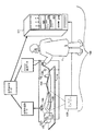
図1について説明すると、本発明の様々な実施形態を適用できるイメージング・システムが示されている。図1において、支持テーブル110上の被検体100が、イメージング・インターフェース123及びイメージング処理装置121を有するイメージング装置120内に配置されており、これらのイメージング・インターフェース123及びイメージング処理装置121は包括的にイメージング装置120と呼ばれる。イメージング装置120は、磁気共鳴イメージング(MRI)装置、X線イメージング装置、コンピュータ断層撮影(CT)スキャナ、ポジトロン放出断層撮影システム又は超音波スキャナ、或いは任意の他の従来の医用イメージング装置であってよい。侵襲性デバイス150(図1には、カテーテルとして示されている)が、通常は医師1によって、被検体100の中に挿入される。デバイス150は、案内ワイヤ、カテーテル、内視鏡、腹腔鏡、生検針、レーザ案内部材、デバイス案内部材、治療用レーザ、又は同様なデバイスであってよい。
Referring to FIG. 1, an imaging system is shown to which various embodiments of the present invention can be applied. In FIG. 1, a
デバイス150は、容易に追跡することが可能である1つ又は複数の素子151を含む。例えば、MRイメージング装置では、素子は、被検体100内で発生されたMR信号を検出するRFコイルであってよい。素子はまた、MRイメージングによって追跡されるフッ素化合物のようなMR活性物質であってよい。RF追跡の場合には、素子は、外部のRFコイル130によって追跡されるRFコイルであってよい。
デバイス追跡ユニット170が、デバイス150上の素子151の位置を、支持テーブル110のような固定の基準点に対して決定する。
RF追跡の場合、デバイス150の場所は、被検体100の周辺にRFコイル130のような数個の外部検出装置と、デバイス150に取り付けられた素子151の少なくとも1つの内部コイルとを用いることによって、決定される。内部コイルはRFエネルギを送出し、このRFエネルギは外部RFコイル130によって受け取る。外部RFコイル130はデバイス追跡ユニット170に接続されている。デバイス追跡ユニット170は内部コイルの位置を時間の経過につれて算出する。エネルギ送出を逆にして、外部コイル130がRFエネルギを送出し、素子151の内部コイルがこの送出されたRFエネルギを受け取るようにしてもよい。
In the case of RF tracking, the location of the
MR追跡の場合には、素子151は、この素子151の周りの局限された領域内の磁気共鳴の章動を検出する。デバイス追跡ユニット170は素子151の場所を決定する。
In the case of MR tracking,
素子151内に2つ以上のコイルが使用されているときには、全てのコイルの場所を決定することにより、デバイス150の配置方向を算出することが可能になる。
When two or more coils are used in the
イメージング装置120内に配置されている位置検出手段190が、被検体100の1つ又は複数の基準点の位置を時間の経過につれて測定する。被検体の参照用画像がイメージング装置120によって時点ti に取得される。被検体100の基準点の位置が位置検出装置190によって同時に監視される。画像及び対応する被検体の場所、並びに位置が記憶される。別の実施形態では、位置検出手段190は、被検体100に固定された発光ダイオード(LED)と、指定された時点にLEDまでの距離を測定することのできる光検出器とを有することができる。また別の実施形態では、位置検出手段190は、従来の超音波距離測定手法を用いて、異なる時点に被検体100上の選択された点の位置を決定する超音波追跡装置を有することができる。また更に別の実施形態では、位置検出手段190は、被検体の解剖学的構造の一部分の幅及び高さを測定するために被検体に物理的に結合された機械的アームのような機械的追跡手段を有することができる。
A
移動検出手段190からの、時間の経過につれての位置情報(被検体追跡データ)は、処理のために被検体追跡ユニット200へ送られる。被検体追跡ユニット200は、時点ti すなわち画像取得時点から、時点td すなわちデバイスの場所の測定時点までの、被検体100の並進及び回転移動量を算出する。この移動量情報は位置合わせユニット160へ送られる。
Position information (subject tracking data) from the movement detection means 190 as time elapses is sent to the
位置合わせユニット160は、(位置合わせデータとして示されている)イメージング装置120からの参照用画像、被検体追跡ユニット200からの正味の被検体の位置及び配置方向の変化、並びにデバイス追跡ユニット170からのデバイス150の位置及び配置方向(デバイス追跡データ)を受け取る。位置合わせユニット160は次いで、参照用画像を並進及び回転させて、デバイス150の場所を測定した時点における被検体100の位置及び配置方向に整合させる。デバイス150の画像、又は素子151の図形が、デバイス追跡ユニット170又は位置合わせユニット160によって合成される。この画像は、その絶対的な場所及び配置方向で被検体100の並進後/回転後の画像に重畳(重ね合わせ)され、その結果、互いに正しく位置合わせされた被検体100及びデバイス150の両方の画像を持つ位置合わせ後の画像が得られる。
The
代替実施形態では、位置合わせユニット160は、逆にデバイス150の絶対的な場所/配置方向を並進させて、並進後の場所/配置方向でデバイス150の画像を参照用画像に重畳することができる。
In an alternative embodiment, the
被検体追跡ユニット200、位置合わせユニット160及びデバイス追跡ユニット170は、例示のためにのみ別々の装置として図示している。一般的に云えば、被検体追跡情報、位置合わせ情報及びデバイス追跡情報は、イメージング装置(図1の処理装置121)によって更なる処理のために送られれる。本発明の様々な実施形態において、処理装置121は、その中に被検体追跡、位置合わせ及びデバイス追跡の処理を含んでいる。
The
本書で提案するものは、医用デバイス案内部材の位置決めのための有効且つ正確に実時間の指針をオペレータに与えるシステムである。このようなシステムは多数の異なる診断用及び介入デバイスを送り込むために使用することが可能である。例えば、システムは治療用レーザ又は生検針案内部材の設置を誘導するために使用することが可能である。 What is proposed herein is a system that provides an operator with effective and accurate real-time guidance for positioning of a medical device guide member. Such a system can be used to deliver a number of different diagnostic and interventional devices. For example, the system can be used to guide the placement of a therapeutic laser or biopsy needle guide member.
図1を参照して更に説明すると、本書では、被検体のイメージングを行いながら被検体について医学的処置を行う際に使用するための医用デバイス位置決めシステムを提供する。本システムは、侵襲性デバイス150のような医用デバイスと、それに対応する追跡装置(例えば、素子151)と、被検体及び医用デバイスの画像を取得するためのイメージング装置120と、被検体上の関心のあるターゲット領域に対するデバイスの動きを検出するための医用デバイス監視サブシステム210とを有する。監視サブシステム210はまた、位置決めシステムのオペレータ1が医用デバイスを位置決めするのを支援するために、インターフェース123のようなインターフェース装置へフィードバックを供給する。医用デバイス150は、処置を実行するために被検体の内部で使用するのに適応しているものであ。本書で用いる用語「医学的処置(medical proceure)」は、それらに限定されないが、生体イメージングのような診断用処置、生体検査、外科的処置、並びに、切除、レーザ処置、超音波処置、ブラティアセラピー(bracheatherapy)などのような治療処置を含む。また、本書で用いる用語「適応している」、「構成され」などは、素子同士が協同して記述された効果を生じることができるように素子同士の間の機械的又は構造的接続を表している。これらの用語はまた、アナログ又はディジタル・コンピュータ、或いは所与の入力に応答して出力を供給するために一連の動作を実行するようにプログラムされている(特定用途向け集積回路(ASIC)のような)特定用途向け装置のような、電気素子の動作能力を表している。
With further reference to FIG. 1, this document provides a medical device positioning system for use in performing medical procedures on a subject while imaging the subject. The system includes a medical device such as the
前に述べたように、医用イメージング装置120は、磁気共鳴イメージング(MRI)装置、X線イメージング装置、コンピュータ断層撮影(CT)スキャナ、ポジトロン放出断層撮影システム又は超音波スキャナ、或いは医学的診断用の参照用画像を得るのに適応している任意の他の従来の医用イメージング装置であってよい。また、デバイス追跡システムは、MR追跡、RF追跡及び当業者に知られている他の方法のような、3次元で実時間位置測定を行うことのできるデバイス追跡システムである。
As previously mentioned, the
デバイス監視サブシステム210は図1の処理装置121内に一体化するのが望ましく、またイメージングしている被検体の関心のあるターゲット領域に対して医用デバイスの位置を監視するのに適応しているものである。デバイス監視サブシステムの更なる実施形態では、該サブシステムは構成ファイルからのデバイス特有の構成情報を有しており、該構成ファイルは、デバイス座標で表したRFコイルの位置のような、追跡方法に対する情報を含んでいると共に、デバイス座標で表した生検針案内部材についての出口孔の位置及び針の長さのような、送り込み情報を更に含んでいる。監視サブシステムはまた図1のインターフェース123に結合されていて、オペレータが、システム座標でターゲットの3D位置を記録すること又は画像上にアイコンのような標識を置くことのいずれかによって、参照用画像上にターゲット位置の座標をマークすることができるようにする。デバイス監視サブシステム210は様々な情報源から入力情報を受け取って、該情報を共通の座標系へ変換するように適応している。情報は、例えば、参照用画像上にオペレータによってマークされたターゲット場所、デバイス案内部材上の追跡される場所の3D座標、又はデバイス特有の追跡及び送り込み情報である。
The device monitoring subsystem 210 is preferably integrated into the
望ましくは、デバイス監視サブシステム210はまた、関心のあるターゲット領域に対する医用デバイスの相対的位置に関してシステムのオペレータにフィードバックを供給するために、望ましくはインターフェース123を介して勧告的フィードバックを供給するように適応している。この能力により、オペレータはデバイスの適切な送り込みのために調節された2次元(2D)又は3次元(3D)位置にターゲットを定めることができ、またデバイス案内部材の現在の2D又は3D位置を実時間で観察することができる。勧告的フィードバックは監視サブシステムからの入力に応じたものであり、その場合の出力が、ターゲット場所へ到達させるためにデバイスを操作し又は位置決めする際に使用するためのオペレータへのフィードバックである。フィードバックは、「案内部材を時計回りに10°回転させよ」というような音声命令、又は「プローブを1インチ前進させよ」というような表示画面(インターフェース123)上のテキスト出力、或いは参照用画像上のターゲット及びデバイス案内部材の相対的位置を示すための可視出力であってよい。
Preferably, the device monitoring subsystem 210 also provides advisory feedback, preferably via the
勧告的フィードバックの可視出力は単に、以下のサンプルのシナリオにおいて述べるように、ターゲット位置とデバイス案内部材の位置とを示す参照用画像上の固有のアイコンとすることができる。それぞれのアイコンが一致したとき、案内部材は所望の位置に到達している。出力はまた、より一層巧妙な表示とすることができる。例えば、デバイス構成ファイルは、デバイス座標において、デバイス案内部材のワイヤーフレーム・モデルの3D座標を含むこともできる。デバイス案内部材の2D投影を2D参照用画像に重畳して、案内部材を位置決めする際の支援手段とすることができる。更に、デバイス構成ファイルは医用デバイスのワイヤーフレーム・モデルの3D座標を含むことができ、その2D投影を参照用画像に重畳して示すことができる。この表示を補足するものとして、投影された針の軌跡又はレーザ経路のようなデバイス特有の情報を追加してもよい。 The visual output of the advisory feedback can simply be a unique icon on the reference image that indicates the target position and the position of the device guide member, as described in the sample scenario below. When the icons match, the guide member has reached the desired position. The output can also be a much more sophisticated display. For example, the device configuration file may include the 3D coordinates of the wireframe model of the device guide member in device coordinates. By superimposing the 2D projection of the device guide member on the 2D reference image, it is possible to provide support means for positioning the guide member. Further, the device configuration file can include 3D coordinates of the wireframe model of the medical device, and the 2D projection can be shown superimposed on the reference image. As a supplement to this display, device specific information such as projected needle trajectory or laser path may be added.
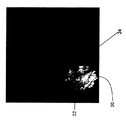
図2について説明すると、図2は、各画像が医用デバイスの追跡された場所と同一平面内にある一対の2D画像を取得した模範例の方法を示している。これらの画像は、デバイスを位置決めする際に役立てるために、同じ平面内で、又は望ましくは異なる平面(例えば、アキシャル、サジタル又はコロナル平面)内で取得することができる。図2Aは、前立腺内部の関心のある領域20、ターゲット・アイコン22及び照準アイコン24を示すアキシャル平面での画像であり、また、図2Bは、後の時点で取得した別の画像、すなわち、前立腺内部のサジタル平面での画像であり、関心のある領域20を異なる方向から見たときの照準アイコンとターゲット・アイコンとの相対的な位置を示している。医学的処置の始めに、オペレータは、取得した両方の画像上のターゲットの場所にターゲット・アイコン22のマークを置く。その結果、固有の静止したターゲット・アイコン22が参照用画像に重畳される。生検針案内部材を位置決めするための処置中に、照準アイコン24が両方の参照用画像上に現れる。デバイスを位置決めするための一実施形態では、オペレータは照準アイコン及びターゲット・アイコンを使用して、デバイスを操作する。この実施形態では、オペレータは、両方の平面において照準アイコン24をターゲット・アイコン22へ近づけるようなやり方でデバイス案内部材を動かす。照準アイコン22が両方の平面においてターゲット・アイコン24と一致したとき、デバイス案内部材は適切に位置決めされており、そこで医学的処置(例えば、生体検査又は治療)が実行可能になる。このとき、オペレータは生検針を挿入して、更なる位置決めを行うことなく生体検査を実行することができる。更に、投影された生検針の経路又はデバイスの輪郭を、操作の目的で使用するために別個の可視出力として表示してもよい。
Referring to FIG. 2, FIG. 2 illustrates an exemplary method of acquiring a pair of 2D images, each image being in the same plane as the tracked location of the medical device. These images can be acquired in the same plane or desirably in different planes (eg, axial, sagittal or coronal planes) to help in positioning the device. FIG. 2A is an image in the axial plane showing the region of
デバイスを監視するための一実施形態では、図1のデバイス監視サブシステム210が画像処理手法を使用して、最も新しく取得した画像を数学的に比較し、その後、比較によりデバイスが許容可能な又は所定の閾値を越えて動いたことが判った場合に、勧告的メッセージ又は出力(例えば、音声又は所定の応答)をインターフェース123へ出力する。
In one embodiment for monitoring a device, the device monitoring subsystem 210 of FIG. 1 uses an image processing technique to mathematically compare the most recently acquired images, after which the device is acceptable by comparison or If it is determined that the movement has exceeded a predetermined threshold, an advisory message or output (eg, voice or a predetermined response) is output to the
更に別の様々な実施形態では、監視サブシステム210は、システム座標において記録された3次元(3D)ターゲット位置を算出し、案内部材に埋め込まれた3つの追跡コイルのデバイス座標を算出し、デバイス座標において生検針出口孔、生検針長さ及び移動のデバイス座標を算出し、更にシステム座標において3つの追跡コイルのシステム座標を算出するように適応している。この情報は、望ましくは、共通の座標系に変換して組み合わせることにより、ターゲットの3D位置を案内部材の3D位置と比較して、生体検査のために案内部材を位置決めするときにアドバイスを構成する。 In still other various embodiments, the monitoring subsystem 210 calculates a three-dimensional (3D) target position recorded in system coordinates, calculates device coordinates of three tracking coils embedded in the guide member, and It is adapted to calculate the biopsy needle outlet hole, biopsy needle length and movement device coordinates in coordinates, and further calculate system coordinates of three tracking coils in system coordinates. This information is preferably converted into a common coordinate system and combined to compare the 3D position of the target with the 3D position of the guide member and constitute advice when positioning the guide member for biopsy .
更に別の様々な実施形態では、医用デバイス監視サブシステム210は被検体内の指定された関心のあるターゲット領域に対する被検体の動き又は医用デバイスの動きのいずれかに応答する。一実施形態では、医用デバイス監視サブシステム210は、医用デバイスの位置が関心のあるターゲット領域から指定の距離だけずれた場合に上記の動きに所定の応答を行うように適応している。例えば、監視サブシステム210は、医用デバイスの動きに予めプログラムされている態様で応答する。例えば、治療を停止し、新しい参照用画像を取得し、デバイス位置決めサブシステムを作動して、デバイスを位置決めし直す際にオペレータを支援するように、又はその代わりに勧告的フィードバックを作動するように応答する。 In yet other various embodiments, the medical device monitoring subsystem 210 is responsive to either subject movement or medical device movement relative to a specified target region of interest within the subject. In one embodiment, the medical device monitoring subsystem 210 is adapted to provide a predetermined response to the above movement when the position of the medical device is shifted a specified distance from the target region of interest. For example, the monitoring subsystem 210 responds in a pre-programmed manner to the movement of the medical device. For example, to stop therapy, acquire a new reference image, activate the device positioning subsystem to assist the operator in repositioning the device, or activate advisory feedback instead respond.
勧告的フィードバックは、図1のインターフェース123を介しての、関心のあるターゲット領域に対する医用デバイスの動きが生じたこと等のオペレータへの出力通知を含む。例えば、勧告的フィードバックは、「デバイスが動きました。レーザは運転停止されました。」と云うような音声出力、「デバイスが動きました。位置決めし直したいですか?」と云うようなテキスト出力、並びに可視出力を含むことができる。一実施形態では、可視出力は、ターゲット位置とデバイスの現在位置とを示す、ターゲット及びデバイスに対応するそれぞれの固有のアイコンとすることができる。別の一実施形態では、可視出力は、デバイス又は案内部材のワイヤーフレーム・モデルの2次元(2D)投影を参照用画像に重畳して示すようにすることができる。更に別の一実施形態では、可視出力は、参照用画像に重畳した医用デバイスの漫画のような表現を含むことができる。可視出力はまた、投影された生検針の軌跡、レーザ経路、出口孔、生検針の長さ及び同様なデバイス送り込み情報のような、デバイス特有の情報を参照用画像上に示すことが望ましい。
Advisory feedback includes an output notification to the operator, such as the occurrence of movement of the medical device relative to the target area of interest, via the
また、本書では、医用デバイスを位置決めするための方法を提供する。本方法は、被検体内の関心のある領域についての少なくとも1つの画像を生成すると共に、該画像には医用デバイスの表現を重畳する段階と、被検体内の関心のあるターゲット領域に対する医用デバイスの位置を監視する段階と、ターゲット領域に対する医用デバイスの位置の変化を検出したときインターフェースへフィードバックを供給する段階とを含んでいる。前に述べたように、フィードバックは、デバイスの位置を表す第1の可視アイコン、関心のあるターゲット領域を表す第2の可視アイコン、テキスト・メッセージ、音声による勧告又は所定の応答を含むことができる。所定の応答には、治療を停止すること、イメージング装置を作動して新しい画像を取得すること、又はインターフェース装置への勧告メッセージを作動することを含むことができる。インターフェースは、医用デバイスのターゲット位置にマークを付けるオペレータによる座標の入力に応答するように適応していることが望ましい。 This document also provides a method for positioning a medical device. The method generates at least one image of a region of interest in the subject, superimposing a representation of the medical device on the image, and the medical device with respect to the target region of interest in the subject. Monitoring the position and providing feedback to the interface when a change in the position of the medical device relative to the target area is detected. As previously mentioned, the feedback can include a first visible icon representing the location of the device, a second visible icon representing the target area of interest, a text message, an audio recommendation, or a predetermined response. . The predetermined response may include stopping therapy, activating the imaging device to acquire a new image, or activating a recommendation message to the interface device. The interface is preferably adapted to respond to coordinate input by an operator marking the target location of the medical device.
特にMRIイメージング用途に関する別の様々な実施形態では、監視サブシステム210は、デバイス座標において、デバイス又は案内部材上のRFコイルの位置などの追跡方法に関連した情報のような、追加のデバイス特有の構成情報から入力を計算する。更に、デバイスを監視するのに有用であると思われる他の入力は、ターゲット位置に位置決めされたときの医用デバイス又は案内部材の質量中心の静的3D座標であってよく、ターゲット位置は、デバイス追跡システムからのデバイス又は案内部材の出発3D位置とデバイス又は案内部材上の被追跡場所とを使用して、監視システムが作動され又は計算を行ったときに記録することができる。この代わりに、デバイス追跡システムからのデバイス又は案内部材上の被追跡場所の実時間3D位置を使用することができる。これらの実施形態では、輪郭描写ビーム(1D投影)がアキシャル、サジタル及びコロナル平面において連続的に取得され、また、輪郭描写ビームは、次のうちの1つ、すなわち、医用デバイス又は案内部材の質量中心の3D位置か、或いはデバイス又は案内部材上の被追跡場所の各々の3D位置を通過する。その後、監視サブシステムが、最も新しく取得された輪郭描写データを以前に取得された輪郭描写データと数学的に比較し、比較によりデバイスがかなり動いたことが判った場合に応答及びフィードバックを作動する。 In various other embodiments, particularly for MRI imaging applications, the monitoring subsystem 210 may provide additional device-specific information, such as information related to tracking methods, such as the position of the RF coil on the device or guide member, in device coordinates. Calculate input from configuration information. Further, another input that may be useful for monitoring the device may be a static 3D coordinate of the center of mass of the medical device or guide member when positioned at the target location, where the target location is the device The starting 3D position of the device or guide member from the tracking system and the tracked location on the device or guide member can be used to record when the monitoring system is activated or performs calculations. Alternatively, the real time 3D location of the tracked location on the device or guide member from the device tracking system can be used. In these embodiments, the contouring beam (1D projection) is acquired continuously in the axial, sagittal and coronal planes, and the contouring beam is one of the following: the mass of the medical device or guide member Pass through the central 3D position or each 3D position of the tracked location on the device or guide member. The monitoring subsystem then mathematically compares the most recently acquired delineation data with previously acquired delineation data and activates response and feedback if the comparison indicates that the device has moved significantly .
別のMRI実施形態では、MRIスキャナにMR追跡システムが装備されている場合、入力は、当該技術分野で知られているような追跡コイルよりはむしろ、ターゲット領域の周りに中心合わせして配置された表面コイルと共に励起のため又は励起データを受け取るために用いられているボディ・コイルからのような、連続的に取得されたMR追跡励起データからであってよい。監視サブシステムは最も新しく取得された励起を以前に取得された励起と数学的に比較し、比較によりデバイスがかなり動いたことが判った場合に応答又はフィードバックを作動する。この実施形態では、デバイスの追跡と動きの検出とが同時に行える。これを行うには、両方の機能のためにスピンを励起するのに同じパルス・シーケンスを使用する。MR追跡コイルが、デバイスの場所を決定するために使用することができる信号を受け取り、他方、表面コイルが、関心のある領域の全体的な状態及び位置を決定するために使用される信号を検出する。 In another MRI embodiment, if the MRI scanner is equipped with an MR tracking system, the input is centered around the target area rather than a tracking coil as known in the art. May be from continuously acquired MR tracking excitation data, such as from a body coil that is being used for excitation or with receiving surface data. The monitoring subsystem mathematically compares the most recently acquired excitation with the previously acquired excitation and activates a response or feedback if the comparison indicates that the device has moved significantly. In this embodiment, device tracking and motion detection can be performed simultaneously. To do this, the same pulse sequence is used to excite the spin for both functions. The MR tracking coil receives a signal that can be used to determine the location of the device, while the surface coil detects a signal that is used to determine the overall state and position of the region of interest. To do.
以上、本発明の好ましい実施形態を図示し説明したが、このような実施形態は例として表したものに過ぎないことが明らかであろう。当業者には本発明から逸脱することなく多数の様々な変形、変更及び置換をなし得よう。従って、本発明は特許請求の範囲に記載の精神及び範囲によって限定されるものとする。 While the preferred embodiment of the invention has been illustrated and described, it will be clear that such embodiment is merely exemplary. Those skilled in the art will be able to make many different variations, modifications and substitutions without departing from the present invention. Accordingly, it is intended that this invention be limited only by the spirit and scope of the appended claims.
1 医師
20 関心のある領域
22 ターゲット・アイコン
24 照準アイコン
100 被検体
110 支持テーブル
120 イメージング装置
121 イメージング処理装置
130 RFコイル
150 侵襲性デバイス
151 素子
190 位置検出手段
DESCRIPTION OF SYMBOLS 1
Claims (7)
医学的処置を実行するために被検体(100)の内部で使用するのに適応し、前記被検体(100)の内部に配置する1つ又は複数の追跡素子を備える医用デバイス(150)と、
前記医用デバイス(150)の配置の間、前記被検体内の関心のある領域についての画像データを取得するためのイメージング装置(120)と、
前記被検体(100)の内部の前記1つ又は複数の追跡素子の位置を特定することにより前記被検体内の関心のあるターゲット領域に対する前記医用デバイスの位置を監視すると共に、前記医用デバイスの位置が関心のあるターゲット領域からずれたときにインターフェース装置へフィードバックを供給する医用デバイス監視サブシステム(210)と、
を有し、
前記フィードバックが前記医用デバイス(150)を前記ターゲット場所へ到達させるために前記医用デバイス(150)を操作し又は位置決めする際に使用するためのオペレータへの命令を含んでいる、
医用デバイス位置決めシステム。A medical device positioning system for use during a medical procedure on a subject (100) performed during imaging comprising:
A medical device (150) adapted for use within a subject (100) to perform a medical procedure and comprising one or more tracking elements disposed within the subject (100);
An imaging device (120) for acquiring image data for a region of interest within the subject during placement of the medical device (150);
Monitoring the position of the medical device relative to a target area of interest within the subject by identifying the position of the one or more tracking elements within the subject (100), and the position of the medical device A medical device monitoring subsystem (210) that provides feedback to the interface device when the is deviated from the target area of interest;
Have,
The feedback includes instructions to an operator for use in manipulating or positioning the medical device (150) to bring the medical device (150) to the target location;
Medical device positioning system.
前記命令は、前記医用デバイス(150)の推奨される移動距離又は移動角度を含み、
前記医用デバイス監視サブシステム(210)は、被検体の動き、及び該被検体内の関心のあるターゲット領域に対する医用デバイスの動きの内の少なくとも1つに応答する、請求項1記載のシステム。 The command is a voice command or text output on a display screen,
The instructions include a recommended travel distance or travel angle of the medical device (150);
The system of claim 1, wherein the medical device monitoring subsystem (210) is responsive to at least one of movement of the subject and movement of the medical device relative to a target region of interest within the subject.
前記医用イメージング装置と前記追跡装置とに結合されていて、前記関心のある領域の画像を生成すると共に、該画像に重畳される前記医用デバイスの可視表現を生成する処理装置(121)と、
を更に有している、請求項1記載のシステム。A tracking device (151) for tracking the location of the medical device;
A processing device (121) coupled to the medical imaging device and the tracking device for generating an image of the region of interest and generating a visual representation of the medical device superimposed on the image;
The system of claim 1, further comprising:
Applications Claiming Priority (2)
| Application Number | Priority Date | Filing Date | Title |
|---|---|---|---|
| US10/064,749 US20040034297A1 (en) | 2002-08-13 | 2002-08-13 | Medical device positioning system and method |
| PCT/US2003/018359 WO2004014246A1 (en) | 2002-08-13 | 2003-06-11 | Medical device positioning system and method |
Publications (3)
| Publication Number | Publication Date |
|---|---|
| JP2005535382A JP2005535382A (en) | 2005-11-24 |
| JP2005535382A5 JP2005535382A5 (en) | 2008-09-11 |
| JP4455995B2 true JP4455995B2 (en) | 2010-04-21 |
Family
ID=31713836
Family Applications (1)
| Application Number | Title | Priority Date | Filing Date |
|---|---|---|---|
| JP2004527564A Expired - Fee Related JP4455995B2 (en) | 2002-08-13 | 2003-06-11 | Medical device positioning system and method |
Country Status (6)
| Country | Link |
|---|---|
| US (1) | US20040034297A1 (en) |
| EP (1) | EP1545365B1 (en) |
| JP (1) | JP4455995B2 (en) |
| CN (1) | CN100391414C (en) |
| DE (1) | DE60317358T2 (en) |
| WO (1) | WO2004014246A1 (en) |
Cited By (1)
| Publication number | Priority date | Publication date | Assignee | Title |
|---|---|---|---|---|
| JP2014534848A (en) * | 2011-10-21 | 2014-12-25 | コーニンクレッカ フィリップス エヌ ヴェ | Body surface feedback for medical intervention |
Families Citing this family (84)
| Publication number | Priority date | Publication date | Assignee | Title |
|---|---|---|---|---|
| US9833167B2 (en) | 1999-05-18 | 2017-12-05 | Mediguide Ltd. | Method and system for superimposing virtual anatomical landmarks on an image |
| US9572519B2 (en) * | 1999-05-18 | 2017-02-21 | Mediguide Ltd. | Method and apparatus for invasive device tracking using organ timing signal generated from MPS sensors |
| US7778688B2 (en) | 1999-05-18 | 2010-08-17 | MediGuide, Ltd. | System and method for delivering a stent to a selected position within a lumen |
| US8442618B2 (en) | 1999-05-18 | 2013-05-14 | Mediguide Ltd. | Method and system for delivering a medical device to a selected position within a lumen |
| US20040057609A1 (en) * | 2002-09-19 | 2004-03-25 | Weinberg Irving N. | Method and apparatus for cross-modality comparisons and correlation |
| US7244234B2 (en) | 2003-11-11 | 2007-07-17 | Soma Development Llc | Ultrasound guided probe device and method of using same |
| EP1746936A4 (en) * | 2004-01-08 | 2010-03-31 | Richard Nuccitelli | Application of the kelvin probe techinique to mammalian skin and other epithelial structures |
| ATE523141T1 (en) | 2004-02-17 | 2011-09-15 | Philips Electronics Ltd | METHOD AND DEVICE FOR REGISTRATION, VERIFICATION OF AND REFERENCE TO BODY ORGANS |
| US20050228270A1 (en) * | 2004-04-02 | 2005-10-13 | Lloyd Charles F | Method and system for geometric distortion free tracking of 3-dimensional objects from 2-dimensional measurements |
| WO2006043276A2 (en) * | 2004-10-19 | 2006-04-27 | Navotek Medical Ltd. | Locating a catheter tip using a tracked guide |
| US7952079B2 (en) * | 2004-08-12 | 2011-05-31 | Navotek Medical Ltd. | Localization of a radioactive source |
| US7847274B2 (en) | 2004-08-12 | 2010-12-07 | Navotek Medical Ltd. | Localization of a radioactive source within a body of a subject |
| JP4348310B2 (en) * | 2004-09-30 | 2009-10-21 | ジーイー・メディカル・システムズ・グローバル・テクノロジー・カンパニー・エルエルシー | Ultrasonic imaging apparatus, image processing apparatus, and program |
| WO2006057786A1 (en) * | 2004-11-05 | 2006-06-01 | The Government Of The United States Of America As Represented By The Secretary, Department Of Health And Human Services | Access system |
| US7805269B2 (en) * | 2004-11-12 | 2010-09-28 | Philips Electronics Ltd | Device and method for ensuring the accuracy of a tracking device in a volume |
| US7751868B2 (en) * | 2004-11-12 | 2010-07-06 | Philips Electronics Ltd | Integrated skin-mounted multifunction device for use in image-guided surgery |
| US8694088B2 (en) * | 2005-01-07 | 2014-04-08 | Bioelectromed Corp. | Hand-held electric field imager for measuring the electric field in mammalian skin and other epithelial structures |
| CA2587986A1 (en) * | 2005-01-18 | 2006-07-27 | Traxtal Inc. | Electromagnetically tracked k-wire device |
| CA2588002A1 (en) * | 2005-01-18 | 2006-07-27 | Traxtal Inc. | Method and apparatus for guiding an instrument to a target in the lung |
| EP1866642A1 (en) * | 2005-03-22 | 2007-12-19 | Bayer Healthcare, LLC | Packaging container for test sensors |
| US7663691B2 (en) * | 2005-10-11 | 2010-02-16 | Apple Inc. | Image capture using display device as light source |
| DE602006019117D1 (en) * | 2005-06-21 | 2011-02-03 | Us Government | DEVICE AND METHOD FOR A TRACKABLE ULTRASOUND |
| CA2613360A1 (en) * | 2005-06-21 | 2007-01-04 | Traxtal Inc. | System, method and apparatus for navigated therapy and diagnosis |
| EP2158940A3 (en) * | 2005-08-11 | 2010-06-02 | Navotek Medical Ltd. | Medical treatment system and method using radioactivity based position sensor |
| BRPI0616514A2 (en) * | 2005-08-11 | 2011-06-21 | Navotek Medical Ltd | medical treatment system and method using position sensor based radioactivity |
| CA2620196A1 (en) * | 2005-08-24 | 2007-03-01 | Traxtal Inc. | System, method and devices for navigated flexible endoscopy |
| DE102005045362B4 (en) * | 2005-09-22 | 2012-03-22 | Siemens Ag | Device for determining the position of a medical instrument, associated imaging examination device and associated method |
| GB0520596D0 (en) * | 2005-10-11 | 2005-11-16 | Sussex Dev Services Llp | Location and stabilization device |
| US20070249930A1 (en) * | 2006-04-24 | 2007-10-25 | General Electric Company | Method and system for tracking devices with multiple rf transmit channels using mri |
| US7777485B2 (en) * | 2006-08-15 | 2010-08-17 | General Electric Company | Method for multiplexed MR tracking |
| US8583213B2 (en) * | 2006-09-12 | 2013-11-12 | General Electric Company | Combined MR imaging and tracking |
| US20080162046A1 (en) * | 2006-10-24 | 2008-07-03 | General Electric Company | Method and system for tracking an arrangement of medical apparatuses |
| CN101401725B (en) * | 2007-09-27 | 2013-08-21 | 西门子公司 | Patient treatment using a hybrid imaging system |
| WO2009129369A1 (en) | 2008-04-16 | 2009-10-22 | Children's Medical Center Corporation | Tissue clip |
| WO2010008720A1 (en) * | 2008-07-18 | 2010-01-21 | Bioelectromed Corp. | Hand-held electric field imager for measuring the surface topography of mammalian skin and other epithelial structures |
| IL199900A0 (en) * | 2008-08-18 | 2010-04-15 | Michal Tune | Implantation device for soft tissue markers and other implants |
| JP5612608B2 (en) * | 2009-01-30 | 2014-10-22 | コーニンクレッカ フィリップス エヌ ヴェ | Inspection device |
| DE102009020000B4 (en) * | 2009-05-05 | 2020-03-12 | Siemens Healthcare Gmbh | Method and control device for operating a magnetic resonance system |
| WO2010144402A2 (en) * | 2009-06-08 | 2010-12-16 | Surgivision, Inc. | Mri-guided surgical systems with preset scan planes |
| JP2012529977A (en) | 2009-06-16 | 2012-11-29 | エムアールアイ・インターヴェンションズ,インコーポレイテッド | MRI guidance device and MRI guidance intervention system capable of tracking the device in near real time and generating a dynamic visualization of the device |
| DE102009033676B4 (en) * | 2009-07-17 | 2018-06-21 | Siemens Healthcare Gmbh | Method for image support the navigation of a particular medical instrument and magnetic resonance device |
| US8761862B2 (en) | 2009-10-09 | 2014-06-24 | Stephen F. Ridley | Ultrasound guided probe device and sterilizable shield for same |
| WO2011083412A1 (en) * | 2010-01-07 | 2011-07-14 | Koninklijke Philips Electronics N.V. | Biopsy planning |
| US8425425B2 (en) | 2010-09-20 | 2013-04-23 | M. Dexter Hagy | Virtual image formation method for an ultrasound device |
| US9439606B2 (en) | 2010-12-09 | 2016-09-13 | Koninklijke Philips N.V. | Interventional apparatus activated computed tomography (CT) |
| US11612377B2 (en) * | 2010-12-16 | 2023-03-28 | Best Medical International, Inc. | Image guided surgical methodology and system employing patient movement detection and correction |
| CN102204846B (en) * | 2011-04-22 | 2012-10-31 | 重庆伟渡医疗设备股份有限公司 | Method for quickly and accurately calibrating medical imaging component after changing of position thereof |
| CN102266250B (en) * | 2011-07-19 | 2013-11-13 | 中国科学院深圳先进技术研究院 | Ultrasonic operation navigation system and ultrasonic operation navigation method |
| CN103957800B (en) * | 2011-11-30 | 2016-04-06 | 富士胶片株式会社 | Medical system |
| EP2785269B1 (en) | 2011-12-03 | 2022-05-11 | Koninklijke Philips N.V. | Robotic guidance of ultrasound probe in endoscopic surgery |
| US9439627B2 (en) | 2012-05-22 | 2016-09-13 | Covidien Lp | Planning system and navigation system for an ablation procedure |
| US9439622B2 (en) | 2012-05-22 | 2016-09-13 | Covidien Lp | Surgical navigation system |
| US8750568B2 (en) | 2012-05-22 | 2014-06-10 | Covidien Lp | System and method for conformal ablation planning |
| US9498182B2 (en) | 2012-05-22 | 2016-11-22 | Covidien Lp | Systems and methods for planning and navigation |
| US9439623B2 (en) | 2012-05-22 | 2016-09-13 | Covidien Lp | Surgical planning system and navigation system |
| WO2014002066A2 (en) | 2012-06-28 | 2014-01-03 | Koninklijke Philips N.V. | Ultrasonically guided biopsies in three dimensions |
| US9739860B2 (en) | 2012-12-28 | 2017-08-22 | General Electric Company | Systems and methods for landmarking for subject imaging |
| JP6386733B2 (en) * | 2013-01-22 | 2018-09-05 | キヤノンメディカルシステムズ株式会社 | X-ray diagnostic apparatus and ultrasonic diagnostic apparatus |
| KR101511299B1 (en) * | 2013-05-16 | 2015-04-13 | 재단법인 아산사회복지재단 | Guiding apparatus for biopsy needle |
| US11690676B2 (en) | 2013-05-31 | 2023-07-04 | Koninklijke Philips N.V. | Assisting apparatus for assisting a user during an interventional procedure |
| JP6545170B2 (en) * | 2013-12-10 | 2019-07-17 | コーニンクレッカ フィリップス エヌ ヴェKoninklijke Philips N.V. | Position determination system |
| CN104055542B (en) * | 2014-05-16 | 2016-05-11 | 张孔源 | Four-dimensional percutaneous biopsy puncture instrument |
| CN104055520B (en) | 2014-06-11 | 2016-02-24 | 清华大学 | Human organ motion monitoring method and operation guiding system |
| US9943374B2 (en) * | 2014-09-16 | 2018-04-17 | X-Nav Technologies, LLC | Image guidance system for detecting and tracking an image pose |
| KR101643622B1 (en) * | 2014-09-25 | 2016-07-29 | 삼성전자주식회사 | Method and ultrasound apparatus for processing an ultrasound image |
| IL236003A (en) * | 2014-11-30 | 2016-02-29 | Ben-Yishai Rani | Model registration system and method |
| WO2016127295A1 (en) * | 2015-02-09 | 2016-08-18 | 北京汇影互联科技有限公司 | Method and device for acquiring position information of region of interest in magnetic resonance system |
| WO2016134916A1 (en) * | 2015-02-23 | 2016-09-01 | Siemens Aktiengesellschaft | Method and system for automated positioning of a medical diagnostic device |
| US10528840B2 (en) | 2015-06-24 | 2020-01-07 | Stryker Corporation | Method and system for surgical instrumentation setup and user preferences |
| CN105054999B (en) * | 2015-08-18 | 2017-06-30 | 浙江工业大学 | A kind of improved intracranial puncture guidance method and device |
| USD801526S1 (en) | 2015-09-30 | 2017-10-31 | Sussex Development Services Llp | Rectal obturator |
| CN108601582B (en) * | 2016-01-26 | 2022-07-08 | 加利福尼亚大学董事会 | System for extraventricular local laser therapy |
| US10132891B2 (en) * | 2016-09-16 | 2018-11-20 | General Electric Company | System and method for attenuation correction of a surface coil in a PET-MRI system |
| CN108577980A (en) * | 2018-02-08 | 2018-09-28 | 南方医科大学南方医院 | A kind of method, system and device ultrasonic cutter head carried out from motion tracking |
| JP7407725B2 (en) * | 2018-03-12 | 2024-01-04 | コーニンクレッカ フィリップス エヌ ヴェ | Ultrasonic imaging plane alignment guidance for neural networks and related devices, systems, and methods |
| US20210100627A1 (en) * | 2018-04-25 | 2021-04-08 | Intuitive Surgical Operations, Inc. | Systems and methods related to elongate devices |
| EP3566670A1 (en) * | 2018-05-07 | 2019-11-13 | Koninklijke Philips N.V. | Safety system for surgical robot |
| US20200046433A1 (en) * | 2018-08-10 | 2020-02-13 | Covidien Lp | Identification and notification of tool displacement during medical procedure |
| US11707329B2 (en) | 2018-08-10 | 2023-07-25 | Covidien Lp | Systems and methods for ablation visualization |
| KR102264077B1 (en) * | 2019-07-01 | 2021-06-11 | 주식회사 리메드 | Medical navigation device |
| CN110301924B (en) * | 2019-07-08 | 2023-05-30 | 东软医疗系统股份有限公司 | Method, device and equipment for processing image |
| WO2022116196A1 (en) * | 2020-12-04 | 2022-06-09 | 西安大医集团股份有限公司 | Real-time position monitoring method, and electronic device, system and storage medium |
| CN114553311A (en) * | 2022-02-18 | 2022-05-27 | 陕西周源光子科技有限公司 | Multi-light-path transmission calibration system and method for CT machine |
| WO2024058826A1 (en) * | 2022-09-15 | 2024-03-21 | Medtronic Vascular, Inc. | Clinical device tracking and monitoring system |
Family Cites Families (10)
| Publication number | Priority date | Publication date | Assignee | Title |
|---|---|---|---|---|
| US5251635A (en) * | 1991-09-03 | 1993-10-12 | General Electric Company | Stereoscopic X-ray fluoroscopy system using radiofrequency fields |
| US5211165A (en) * | 1991-09-03 | 1993-05-18 | General Electric Company | Tracking system to follow the position and orientation of a device with radiofrequency field gradients |
| US5375596A (en) * | 1992-09-29 | 1994-12-27 | Hdc Corporation | Method and apparatus for determining the position of catheters, tubes, placement guidewires and implantable ports within biological tissue |
| US5617857A (en) * | 1995-06-06 | 1997-04-08 | Image Guided Technologies, Inc. | Imaging system having interactive medical instruments and methods |
| US6058323A (en) * | 1996-11-05 | 2000-05-02 | Lemelson; Jerome | System and method for treating select tissue in a living being |
| US6119033A (en) * | 1997-03-04 | 2000-09-12 | Biotrack, Inc. | Method of monitoring a location of an area of interest within a patient during a medical procedure |
| US5916163A (en) * | 1997-03-07 | 1999-06-29 | Ep Technologies, Inc. | Graphical user interface for use with multiple electrode catheters |
| US6149592A (en) * | 1997-11-26 | 2000-11-21 | Picker International, Inc. | Integrated fluoroscopic projection image data, volumetric image data, and surgical device position data |
| US6285902B1 (en) * | 1999-02-10 | 2001-09-04 | Surgical Insights, Inc. | Computer assisted targeting device for use in orthopaedic surgery |
| DE10051244A1 (en) * | 2000-10-17 | 2002-05-16 | Philips Corp Intellectual Pty | X-ray free intravascular localization and imaging procedure |
-
2002
- 2002-08-13 US US10/064,749 patent/US20040034297A1/en not_active Abandoned
-
2003
- 2003-06-11 JP JP2004527564A patent/JP4455995B2/en not_active Expired - Fee Related
- 2003-06-11 CN CNB038169967A patent/CN100391414C/en not_active Expired - Fee Related
- 2003-06-11 EP EP03734536A patent/EP1545365B1/en not_active Expired - Fee Related
- 2003-06-11 WO PCT/US2003/018359 patent/WO2004014246A1/en active IP Right Grant
- 2003-06-11 DE DE60317358T patent/DE60317358T2/en not_active Expired - Lifetime
Cited By (1)
| Publication number | Priority date | Publication date | Assignee | Title |
|---|---|---|---|---|
| JP2014534848A (en) * | 2011-10-21 | 2014-12-25 | コーニンクレッカ フィリップス エヌ ヴェ | Body surface feedback for medical intervention |
Also Published As
| Publication number | Publication date |
|---|---|
| DE60317358D1 (en) | 2007-12-20 |
| JP2005535382A (en) | 2005-11-24 |
| CN100391414C (en) | 2008-06-04 |
| CN1668254A (en) | 2005-09-14 |
| DE60317358T2 (en) | 2008-08-21 |
| US20040034297A1 (en) | 2004-02-19 |
| EP1545365A1 (en) | 2005-06-29 |
| EP1545365B1 (en) | 2007-11-07 |
| WO2004014246A1 (en) | 2004-02-19 |
Similar Documents
| Publication | Publication Date | Title |
|---|---|---|
| JP4455995B2 (en) | Medical device positioning system and method | |
| RU2464931C2 (en) | Device for determining position of first object inside second object | |
| JP5248474B2 (en) | Targeting method, targeting device, computer-readable medium, and program element | |
| US8798339B2 (en) | Targeting method, targeting device, computer readable medium and program element | |
| JP6404713B2 (en) | System and method for guided injection in endoscopic surgery | |
| EP0501993B1 (en) | Probe-correlated viewing of anatomical image data | |
| JP2010519635A (en) | Pointing device for medical imaging | |
| JP2009531113A (en) | Image guided surgery system | |
| JP2010269067A (en) | Treatment support device | |
| JP2005535382A5 (en) | ||
| US20150335316A1 (en) | Mri system for robotically assisted breast biopsy | |
| JP2006326298A (en) | Method and system for acquiring image by medical imaging device | |
| JP2018183589A (en) | Endoscopic view of invasive procedures in narrow passages | |
| CN108289714B (en) | System and workflow for mesh-free transperineal prostate intervention | |
| JP6740316B2 (en) | Radiation-free position calibration of fluoroscope | |
| US20170000380A1 (en) | Method and system for electromagnetic tracking with magnetic trackers for respiratory monitoring | |
| US20220409290A1 (en) | Method and system for reproducing an insertion point for a medical instrument | |
| WO2008035271A2 (en) | Device for registering a 3d model | |
| JP4717683B2 (en) | Medical image display device | |
| KR20160069180A (en) | CT-Robot Registration System for Interventional Robot | |
| EP3968861A1 (en) | Ultrasound system and method for tracking movement of an object | |
| US20110257508A1 (en) | Device For Supporting, Scanning, Tomographically Displaying A Patient And Carrying Out An Intervention And Method For Determining The Spatial Relation Between Optical Recordings And Tomographic Displays | |
| US11789099B2 (en) | System and method for guiding an invasive device | |
| EP3738515A1 (en) | Ultrasound system and method for tracking movement of an object | |
| Adams et al. | An optical navigator for brain surgery |
Legal Events
| Date | Code | Title | Description |
|---|---|---|---|
| A621 | Written request for application examination |
Free format text: JAPANESE INTERMEDIATE CODE: A621 Effective date: 20060607 |
|
| A521 | Request for written amendment filed |
Free format text: JAPANESE INTERMEDIATE CODE: A523 Effective date: 20080722 |
|
| A131 | Notification of reasons for refusal |
Free format text: JAPANESE INTERMEDIATE CODE: A131 Effective date: 20090707 |
|
| A601 | Written request for extension of time |
Free format text: JAPANESE INTERMEDIATE CODE: A601 Effective date: 20090915 |
|
| RD02 | Notification of acceptance of power of attorney |
Free format text: JAPANESE INTERMEDIATE CODE: A7422 Effective date: 20090915 |
|
| RD04 | Notification of resignation of power of attorney |
Free format text: JAPANESE INTERMEDIATE CODE: A7424 Effective date: 20090915 |
|
| A602 | Written permission of extension of time |
Free format text: JAPANESE INTERMEDIATE CODE: A602 Effective date: 20090925 |
|
| A521 | Request for written amendment filed |
Free format text: JAPANESE INTERMEDIATE CODE: A523 Effective date: 20091202 |
|
| TRDD | Decision of grant or rejection written | ||
| A01 | Written decision to grant a patent or to grant a registration (utility model) |
Free format text: JAPANESE INTERMEDIATE CODE: A01 Effective date: 20100112 |
|
| A01 | Written decision to grant a patent or to grant a registration (utility model) |
Free format text: JAPANESE INTERMEDIATE CODE: A01 |
|
| A61 | First payment of annual fees (during grant procedure) |
Free format text: JAPANESE INTERMEDIATE CODE: A61 Effective date: 20100204 |
|
| FPAY | Renewal fee payment (event date is renewal date of database) |
Free format text: PAYMENT UNTIL: 20130212 Year of fee payment: 3 |
|
| R150 | Certificate of patent or registration of utility model |
Free format text: JAPANESE INTERMEDIATE CODE: R150 |
|
| FPAY | Renewal fee payment (event date is renewal date of database) |
Free format text: PAYMENT UNTIL: 20140212 Year of fee payment: 4 |
|
| R250 | Receipt of annual fees |
Free format text: JAPANESE INTERMEDIATE CODE: R250 |
|
| R250 | Receipt of annual fees |
Free format text: JAPANESE INTERMEDIATE CODE: R250 |
|
| R250 | Receipt of annual fees |
Free format text: JAPANESE INTERMEDIATE CODE: R250 |
|
| LAPS | Cancellation because of no payment of annual fees |