JP2019140430A - Reproduction device - Google Patents
Reproduction device Download PDFInfo
- Publication number
- JP2019140430A JP2019140430A JP2018019058A JP2018019058A JP2019140430A JP 2019140430 A JP2019140430 A JP 2019140430A JP 2018019058 A JP2018019058 A JP 2018019058A JP 2018019058 A JP2018019058 A JP 2018019058A JP 2019140430 A JP2019140430 A JP 2019140430A
- Authority
- JP
- Japan
- Prior art keywords
- display device
- information
- playback device
- playback
- luminance range
- Prior art date
- Legal status (The legal status is an assumption and is not a legal conclusion. Google has not performed a legal analysis and makes no representation as to the accuracy of the status listed.)
- Pending
Links
Images


Classifications
-
- G—PHYSICS
- G09—EDUCATION; CRYPTOGRAPHY; DISPLAY; ADVERTISING; SEALS
- G09G—ARRANGEMENTS OR CIRCUITS FOR CONTROL OF INDICATING DEVICES USING STATIC MEANS TO PRESENT VARIABLE INFORMATION
- G09G5/00—Control arrangements or circuits for visual indicators common to cathode-ray tube indicators and other visual indicators
- G09G5/02—Control arrangements or circuits for visual indicators common to cathode-ray tube indicators and other visual indicators characterised by the way in which colour is displayed
- G09G5/04—Control arrangements or circuits for visual indicators common to cathode-ray tube indicators and other visual indicators characterised by the way in which colour is displayed using circuits for interfacing with colour displays
-
- H—ELECTRICITY
- H04—ELECTRIC COMMUNICATION TECHNIQUE
- H04N—PICTORIAL COMMUNICATION, e.g. TELEVISION
- H04N21/00—Selective content distribution, e.g. interactive television or video on demand [VOD]
- H04N21/40—Client devices specifically adapted for the reception of or interaction with content, e.g. set-top-box [STB]; Operations thereof
- H04N21/43—Processing of content or additional data, e.g. demultiplexing additional data from a digital video stream; Elementary client operations, e.g. monitoring of home network or synchronising decoder's clock; Client middleware
- H04N21/436—Interfacing a local distribution network, e.g. communicating with another STB or one or more peripheral devices inside the home
- H04N21/4363—Adapting the video or multiplex stream to a specific local network, e.g. a IEEE 1394 or Bluetooth® network
- H04N21/43632—Adapting the video or multiplex stream to a specific local network, e.g. a IEEE 1394 or Bluetooth® network involving a wired protocol, e.g. IEEE 1394
- H04N21/43635—HDMI
-
- G—PHYSICS
- G09—EDUCATION; CRYPTOGRAPHY; DISPLAY; ADVERTISING; SEALS
- G09G—ARRANGEMENTS OR CIRCUITS FOR CONTROL OF INDICATING DEVICES USING STATIC MEANS TO PRESENT VARIABLE INFORMATION
- G09G5/00—Control arrangements or circuits for visual indicators common to cathode-ray tube indicators and other visual indicators
- G09G5/02—Control arrangements or circuits for visual indicators common to cathode-ray tube indicators and other visual indicators characterised by the way in which colour is displayed
- G09G5/026—Control of mixing and/or overlay of colours in general
-
- G—PHYSICS
- G09—EDUCATION; CRYPTOGRAPHY; DISPLAY; ADVERTISING; SEALS
- G09G—ARRANGEMENTS OR CIRCUITS FOR CONTROL OF INDICATING DEVICES USING STATIC MEANS TO PRESENT VARIABLE INFORMATION
- G09G5/00—Control arrangements or circuits for visual indicators common to cathode-ray tube indicators and other visual indicators
- G09G5/10—Intensity circuits
-
- H—ELECTRICITY
- H04—ELECTRIC COMMUNICATION TECHNIQUE
- H04N—PICTORIAL COMMUNICATION, e.g. TELEVISION
- H04N21/00—Selective content distribution, e.g. interactive television or video on demand [VOD]
- H04N21/40—Client devices specifically adapted for the reception of or interaction with content, e.g. set-top-box [STB]; Operations thereof
- H04N21/47—End-user applications
- H04N21/472—End-user interface for requesting content, additional data or services; End-user interface for interacting with content, e.g. for content reservation or setting reminders, for requesting event notification, for manipulating displayed content
- H04N21/47217—End-user interface for requesting content, additional data or services; End-user interface for interacting with content, e.g. for content reservation or setting reminders, for requesting event notification, for manipulating displayed content for controlling playback functions for recorded or on-demand content, e.g. using progress bars, mode or play-point indicators or bookmarks
-
- H—ELECTRICITY
- H04—ELECTRIC COMMUNICATION TECHNIQUE
- H04N—PICTORIAL COMMUNICATION, e.g. TELEVISION
- H04N5/00—Details of television systems
- H04N5/76—Television signal recording
- H04N5/765—Interface circuits between an apparatus for recording and another apparatus
-
- H—ELECTRICITY
- H04—ELECTRIC COMMUNICATION TECHNIQUE
- H04N—PICTORIAL COMMUNICATION, e.g. TELEVISION
- H04N5/00—Details of television systems
- H04N5/76—Television signal recording
- H04N5/91—Television signal processing therefor
- H04N5/93—Regeneration of the television signal or of selected parts thereof
-
- G—PHYSICS
- G09—EDUCATION; CRYPTOGRAPHY; DISPLAY; ADVERTISING; SEALS
- G09G—ARRANGEMENTS OR CIRCUITS FOR CONTROL OF INDICATING DEVICES USING STATIC MEANS TO PRESENT VARIABLE INFORMATION
- G09G2320/00—Control of display operating conditions
- G09G2320/02—Improving the quality of display appearance
- G09G2320/0242—Compensation of deficiencies in the appearance of colours
-
- G—PHYSICS
- G09—EDUCATION; CRYPTOGRAPHY; DISPLAY; ADVERTISING; SEALS
- G09G—ARRANGEMENTS OR CIRCUITS FOR CONTROL OF INDICATING DEVICES USING STATIC MEANS TO PRESENT VARIABLE INFORMATION
- G09G2320/00—Control of display operating conditions
- G09G2320/06—Adjustment of display parameters
- G09G2320/0626—Adjustment of display parameters for control of overall brightness
-
- G—PHYSICS
- G09—EDUCATION; CRYPTOGRAPHY; DISPLAY; ADVERTISING; SEALS
- G09G—ARRANGEMENTS OR CIRCUITS FOR CONTROL OF INDICATING DEVICES USING STATIC MEANS TO PRESENT VARIABLE INFORMATION
- G09G2370/00—Aspects of data communication
- G09G2370/04—Exchange of auxiliary data, i.e. other than image data, between monitor and graphics controller
- G09G2370/042—Exchange of auxiliary data, i.e. other than image data, between monitor and graphics controller for monitor identification
-
- H—ELECTRICITY
- H04—ELECTRIC COMMUNICATION TECHNIQUE
- H04N—PICTORIAL COMMUNICATION, e.g. TELEVISION
- H04N21/00—Selective content distribution, e.g. interactive television or video on demand [VOD]
- H04N21/40—Client devices specifically adapted for the reception of or interaction with content, e.g. set-top-box [STB]; Operations thereof
- H04N21/47—End-user applications
- H04N21/485—End-user interface for client configuration
- H04N21/4854—End-user interface for client configuration for modifying image parameters, e.g. image brightness, contrast
Abstract
Description
本発明は、表示装置と接続される再生装置に関する。 The present invention relates to a playback device connected to a display device.
例えばDVD(Digital Versatile Disc)プレーヤ又はBD(Blu−ray(登録商標) Disc)プレーヤ等の再生装置が知られている。この再生装置は、例えばテレビジョン受像機等の表示装置と接続される。再生装置と表示装置との間で映像信号等を高速で伝送するための通信インタフェースとして、HDMI(High Definition Multimedia Interface)(登録商標)が用いられる。そのため、表示装置及び再生装置の各々は、HDMI接続するためのHDMI端子を備えている。 For example, a reproducing apparatus such as a DVD (Digital Versatile Disc) player or a BD (Blu-ray (registered trademark) Disc) player is known. This playback device is connected to a display device such as a television receiver. HDMI (High Definition Multimedia Interface) (registered trademark) is used as a communication interface for transmitting a video signal or the like between a playback device and a display device at high speed. Therefore, each of the display device and the playback device includes an HDMI terminal for HDMI connection.
近年、SDR(Standard Dynamic Range)よりも輝度範囲が拡大されたHDR(High Dynamic Range)対応の映像コンテンツを再生可能な再生装置が提案されている(例えば、特許文献1参照)。HDR対応の映像コンテンツを再生するためには、ユーザは、再生装置を表示装置のHDR対応のHDMI端子に接続し、且つ、表示装置側で輝度範囲をHDRに設定するための操作を実行する必要がある。 In recent years, there has been proposed a playback apparatus capable of playing back HDR (High Dynamic Range) -compatible video content whose luminance range is wider than SDR (Standard Dynamic Range) (see, for example, Patent Document 1). In order to play back HDR-compatible video content, the user needs to connect the playback device to the HDR-compatible HDMI terminal of the display device and execute an operation for setting the luminance range to HDR on the display device side. There is.
しかしながら、再生装置等の操作に不慣れなユーザは、再生装置が表示装置のHDR非対応のHDMI端子に接続されている状態で、あるいは、表示装置側で輝度範囲がSDRに設定されている状態で、HDR対応の映像コンテンツを再生してしまう場合がある。このような場合には、HDR対応の映像コンテンツが再生装置から表示装置に正しく出力されないという課題が生じる。 However, a user who is unfamiliar with the operation of the playback device or the like is in a state where the playback device is connected to an HDMI terminal that does not support HDR, or in a state where the luminance range is set to SDR on the display device side. In some cases, HDR-compatible video content is played back. In such a case, there arises a problem that HDR-compatible video content is not correctly output from the playback device to the display device.
本発明は、上述した課題を解決しようとするものであり、その目的は、特定の輝度範囲への設定変更に関する情報をユーザに提供することができる再生装置を提供することである。 The present invention is intended to solve the above-described problems, and an object of the present invention is to provide a playback apparatus that can provide a user with information regarding a setting change to a specific luminance range.
上記目的を達成するために、本発明の一態様に係る再生装置は、表示装置と接続される再生装置であって、前記表示装置と通信する通信部と、前記表示装置における輝度範囲の現在の設定内容を示す設定情報を、前記表示装置から前記通信部を介して取得する制御部と、を備え、前記制御部は、前記表示装置において特定の輝度範囲に設定されていない場合に、前記表示装置と当該表示装置において設定可能な輝度範囲との対応関係を示す対応情報に基づいて、前記特定の輝度範囲への設定変更に関する情報を、前記通信部を介して前記表示装置に送信する。 In order to achieve the above object, a playback device according to one aspect of the present invention is a playback device connected to a display device, the communication unit communicating with the display device, and the current luminance range in the display device A control unit that acquires setting information indicating setting content from the display device via the communication unit, and the control unit displays the display when the display device is not set to a specific luminance range. Based on correspondence information indicating a correspondence relationship between a device and a luminance range that can be set in the display device, information related to a setting change to the specific luminance range is transmitted to the display device via the communication unit.
本態様によれば、表示装置において特定の輝度範囲に設定されていない場合に、対応情報に基づいて特定の輝度範囲への設定変更に関する情報を表示装置に送信するので、特定の輝度範囲への設定変更に関する情報をユーザに提供することができる。これにより、例えば、ユーザは、提供された情報に基づいて、表示装置において特定の輝度範囲に設定変更する操作等を実行することができる。 According to this aspect, when the display device is not set to the specific luminance range, the information regarding the setting change to the specific luminance range is transmitted to the display device based on the correspondence information. Information regarding the setting change can be provided to the user. Thereby, for example, the user can execute an operation for changing the setting to a specific luminance range on the display device based on the provided information.
例えば、本発明の一態様に係る再生装置において、前記再生装置は、さらに、前記対応情報を予め記憶する記憶部を備えるように構成してもよい。 For example, in the playback apparatus according to an aspect of the present invention, the playback apparatus may further include a storage unit that stores the correspondence information in advance.
本態様によれば、対応情報を再生装置に予め記憶しておくことができる。これにより、対応情報を記憶部から比較的短時間で読み出すことができる。 According to this aspect, correspondence information can be stored in the playback device in advance. As a result, the correspondence information can be read from the storage unit in a relatively short time.
例えば、本発明の一態様に係る再生装置において、前記再生装置は、さらに、前記対応情報を更新するための更新情報を保持する外部装置とネットワークを介して接続可能であり、前記再生装置は、さらに、前記外部装置からの前記更新情報を受信する受信部を備え、前記制御部は、さらに、受信された前記更新情報に基づいて、前記対応情報を更新するように構成してもよい。 For example, in the playback device according to one aspect of the present invention, the playback device can be further connected via a network to an external device that holds update information for updating the correspondence information. Furthermore, a receiving unit that receives the update information from the external device may be provided, and the control unit may further be configured to update the correspondence information based on the received update information.
本態様によれば、外部装置からの更新情報に基づいて対応情報を更新することができる。 According to this aspect, the correspondence information can be updated based on the update information from the external device.
例えば、本発明の一態様に係る再生装置において、前記再生装置は、さらに、前記対応情報を保持する外部装置とネットワークを介して接続可能であり、前記再生装置は、さらに、前記外部装置に対して前記対応情報の送信を要求するための要求信号を前記外部装置に送信し、前記要求信号に基づいて前記外部装置から送信された前記対応情報を受信する送受信部を備えるように構成してもよい。 For example, in the playback device according to one aspect of the present invention, the playback device can be further connected to an external device that holds the correspondence information via a network, and the playback device is further connected to the external device. A transmission / reception unit configured to transmit a request signal for requesting transmission of the correspondence information to the external device and receive the correspondence information transmitted from the external device based on the request signal. Good.
本態様によれば、対応情報が外部装置に保持されているので、対応情報を再生装置に予め記憶させておく必要が無く、再生装置における記憶容量を節約することができる。また、外部装置において対応情報の更新処理を容易に実行することができる。 According to this aspect, since the correspondence information is held in the external device, it is not necessary to store the correspondence information in the reproduction device in advance, and the storage capacity in the reproduction device can be saved. In addition, it is possible to easily execute the update process of the correspondence information in the external device.
例えば、本発明の一態様に係る再生装置において、前記対応情報は、複数種類の前記表示装置の各々と、当該表示装置において設定可能な輝度範囲との対応関係を示す情報であるように構成してもよい。 For example, in the playback device according to one aspect of the present invention, the correspondence information is configured to be information indicating a correspondence relationship between each of the plurality of types of display devices and a luminance range that can be set in the display device. May be.
本態様によれば、対応情報が例えば各社製の表示装置に関する情報を含むことにより、対応情報の汎用性を高めることができる。 According to this aspect, the versatility of correspondence information can be improved because correspondence information contains the information regarding the display apparatus made from each company, for example.
例えば、本発明の一態様に係る再生装置において、前記制御部は、さらに、前記表示装置に対して前記対応情報の送信を要求するための要求信号を、前記通信部を介して前記表示装置に送信し、前記要求信号に基づいて前記表示装置から送信された前記対応情報を、前記通信部を介して受信するように構成してもよい。 For example, in the playback device according to one aspect of the present invention, the control unit further sends a request signal for requesting the display device to transmit the correspondence information to the display device via the communication unit. The correspondence information transmitted from the display device based on the request signal may be received via the communication unit.
本態様によれば、対応情報が表示装置に保持されているので、対応情報を再生装置に予め記憶させておく必要が無く、再生装置における記憶容量を節約することができる。 According to this aspect, since the correspondence information is held in the display device, it is not necessary to store the correspondence information in the reproduction device in advance, and the storage capacity in the reproduction device can be saved.
例えば、本発明の一態様に係る再生装置において、前記表示装置は、前記再生装置と接続するための複数の接続端子を備えており、前記制御部は、さらに、前記再生装置が前記複数の接続端子の各々と接続される毎に前記設定情報を取得し、取得した複数の前記設定情報に基づいて前記対応情報を生成するように構成してもよい。 For example, in the playback device according to one aspect of the present invention, the display device includes a plurality of connection terminals for connection to the playback device, and the control unit further includes the connection of the playback device to the plurality of connections. You may comprise so that the said setting information may be acquired whenever it connects with each of each terminal, and the said corresponding | compatible information is produced | generated based on the acquired some said setting information.
本態様によれば、例えば再生装置を購入後に初めて起動する際に、ユーザが再生装置を複数の接続端子の各々と順に接続することにより、接続する毎に取得した複数の設定情報に基づいて対応情報を生成することができる。 According to this aspect, for example, when the playback device is activated for the first time after purchase, the user connects the playback device to each of the plurality of connection terminals in order, and thereby responds based on a plurality of setting information acquired each time the user connects. Information can be generated.
例えば、本発明の一態様に係る再生装置において、前記対応情報は、前記表示装置において前記特定の輝度範囲に設定する方法を示す設定方法情報を含み、前記制御部は、前記設定方法情報に基づいて、前記表示装置に対して前記特定の輝度範囲に設定変更するように指示するための指示情報を、前記通信部を介して前記表示装置に送信するように構成してもよい。 For example, in the playback device according to one aspect of the present invention, the correspondence information includes setting method information indicating a method of setting the specific luminance range in the display device, and the control unit is based on the setting method information. In addition, instruction information for instructing the display device to change the setting to the specific luminance range may be transmitted to the display device via the communication unit.
本態様によれば、表示装置に対して特定の輝度範囲に設定変更するように指示するための指示情報を表示装置に送信するので、表示装置において特定の輝度範囲に自動で設定変更することができる。これにより、ユーザの利便性を高めることができる。 According to this aspect, the instruction information for instructing the display device to change the setting to the specific luminance range is transmitted to the display device. Therefore, the display device can automatically change the setting to the specific luminance range. it can. Thereby, a user's convenience can be improved.
例えば、本発明の一態様に係る再生装置において、前記設定情報は、EDID(Extended Display Identification Data)情報であり、前記特定の輝度範囲は、HDR(High Dynamic Range)であるように構成してもよい。 For example, in the playback device according to an aspect of the present invention, the setting information may be configured to be EDID (Extended Display Identification Data) information, and the specific luminance range may be HDR (High Dynamic Range). Good.
なお、本発明は、再生装置に含まれる特徴的な処理部としてコンピュータを機能させるためのプログラム又は再生方法に含まれる特徴的なステップをコンピュータに実行させるプログラムとして実現することもできる。そして、そのようなプログラムを、CD−ROM(Compact Disc−Read Only Memory)等のコンピュータ読取可能な非一時的な記録媒体やインターネット等の通信ネットワークを介して流通させることができるのは、言うまでもない。 Note that the present invention can also be implemented as a program for causing a computer to function as a characteristic processing unit included in a playback apparatus or a program for causing a computer to execute characteristic steps included in a playback method. Such a program can be distributed via a computer-readable non-transitory recording medium such as a CD-ROM (Compact Disc-Read Only Memory) or a communication network such as the Internet. .
本発明の一態様に係る再生装置によれば、特定の輝度範囲への設定変更に関する情報をユーザに提供することができる。 According to the playback apparatus according to one aspect of the present invention, it is possible to provide a user with information related to a setting change to a specific luminance range.
以下、本発明の実施の形態について、図面を用いて詳細に説明する。なお、以下で説明する実施の形態は、いずれも包括的または具体的な例を示すものである。以下の実施の形態で示される数値、形状、材料、構成要素、構成要素の配置位置及び接続形態などは、一例であり、本発明を限定する主旨ではない。また、以下の実施の形態における構成要素のうち、独立請求項に記載されていない構成要素については、任意の構成要素として説明される。 Hereinafter, embodiments of the present invention will be described in detail with reference to the drawings. It should be noted that each of the embodiments described below shows a comprehensive or specific example. Numerical values, shapes, materials, constituent elements, arrangement positions and connection forms of constituent elements, and the like shown in the following embodiments are merely examples, and are not intended to limit the present invention. In addition, among the constituent elements in the following embodiments, constituent elements that are not described in the independent claims are described as arbitrary constituent elements.
(実施の形態1)
[1−1.再生システムの構成]
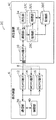
まず、図1を参照しながら、実施の形態1に係る再生システム2の構成について説明する。図1は、実施の形態1に係る再生システム2の構成を示すブロック図である。
(Embodiment 1)
[1-1. Configuration of playback system]
First, the configuration of the reproduction system 2 according to
図1に示すように、再生システム2は、再生装置4と、表示装置6とを備えている。再生装置4は、例えば、DVD又はBD等に格納された映像コンテンツを再生するためのデジタルビデオプレーヤである。表示装置6は、例えば、再生装置4により再生された映像コンテンツを表示するためのテレビジョン受像機である。
As shown in FIG. 1, the playback system 2 includes a
再生装置4及び表示装置6は、いずれもHDMI機器である。再生装置4と表示装置6とは、HDMIケーブル8を介して相互に接続されている。HDMIケーブル8は、HDMI規格に準拠したケーブルであり、デジタル信号を伝送するためのケーブルである。なお、HDMI規格とは、映像信号及び音声信号をデジタル信号で伝送する通信インタフェースの標準規格である。
Both the
再生装置4は、HDMIケーブル8を接続するためのHDMI端子10を備えている。また、表示装置6は、HDMIケーブル8を接続するための複数のHDMI端子12,14及び16(複数の接続端子の一例)を備えている。なお、以下の説明において、複数のHDMI端子12,14及び16をそれぞれ、「HDMI端子1」、「HDMI端子2」及び「HDMI端子3」と呼ぶことがある。
The
また、再生装置4は、ネットワーク18を介してサーバ装置20(外部装置の一例)と接続されている。サーバ装置20は、後述する対応情報の更新(アップデート)に関する更新情報が格納された記憶部22を備えている。なお、ネットワーク18は、例えばインターネットである。
Further, the
[1−2.再生装置の構成]
次に、図1及び図2を参照しながら、実施の形態1に係る再生装置4の構成について説明する。図2は、実施の形態1に係る対応情報の一例を示す図である。
[1-2. Configuration of playback device]
Next, the configuration of the
図1に示すように、再生装置4は、再生部24と、通信部26と、取得部28と、記憶部30と、処理部32と、受信部34と、更新実行部36とを備えている。なお、取得部28、処理部32及び更新実行部36は、制御部37を構成する。制御部37は、例えばプロセッサがハードディスク又は半導体メモリ等の記録媒体に記録されたソフトウェアプログラムを読み出して実行することによって実現される。
As shown in FIG. 1, the
再生部24は、例えばDVD又はBD等に格納された映像コンテンツを再生する。映像コンテンツは、例えばHDR対応の映像コンテンツである。
The
通信部26は、HDMI端子10及びHDMIケーブル8を介して、表示装置6との間で各種データを送受信する。具体的には、通信部26は、例えば表示装置6から送信されたEDID(Extended Display Identification Data)情報等を受信する。また、通信部26は、再生部24により再生された映像コンテンツ及び処理部32により生成された画像信号等を表示装置6に送信する。
The
なお、EDID情報は、例えば、a)表示装置6の対応解像度、b)表示装置6のメーカー名、c)表示装置6の型番、及び、d)表示装置6における輝度範囲の現在の設定内容を示す設定情報等を含むデータである。すなわち、EDID情報は、表示装置6における輝度範囲の現在の設定内容を示す設定情報の一例である。なお、表示装置6では、HDMI端子12,14及び16毎に、輝度範囲としてHDR(特定の輝度範囲の一例)及びSDRのいずれかを設定可能である。
The EDID information includes, for example, a) the corresponding resolution of the
取得部28は、通信部26を介して、表示装置6から送信されたEDID情報を取得する。取得部28は、取得したEDID情報を処理部32に出力する。
The
記憶部30は、対応情報を予め記憶するためのメモリである。対応情報は、複数種類の表示装置の各々と、当該表示装置において設定可能な輝度範囲との対応関係を示すデータテーブルである。
The
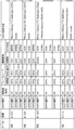
対応情報は、例えば図2に示すようなデータテーブルである。図2に示す例では、対応情報は、再生装置4に接続されている表示装置6を含む、現在市場で販売されている各社製の種々の機種の表示装置に関する情報を含んでいる。例えば、対応情報の2行目には、「A社」製の型番「A−105」の表示装置に関する情報が格納されている。具体的には、対応情報の2行目には、a)表示装置のメーカー名「A社」、b)表示装置の型番「A−105」、c)表示装置のHDMI端子の種類「HDMI端子1〜3」、d)各HDMI端子の対応解像度「4K」、e)各HDMI端子の対応フレームレート「60Hz」、f)各HDMI端子の対応輝度範囲「HDR/非対応」、及び、g)輝度範囲を設定する方法を示す設定方法情報「Menu>Setup>TV Settings>HDMI mode」が格納されている。
The correspondence information is, for example, a data table as shown in FIG. In the example shown in FIG. 2, the correspondence information includes information on various types of display devices manufactured by various companies currently sold in the market, including the
ここで、対応輝度範囲については、「HDMI端子1」及び「HDMI端子2」の各々はHDRに対応しているが、「HDMI端子3」はHDRに対応していないことを示している。なお、「HDMI端子1」では、輝度範囲の設定の初期値が「HDR」であるため、HDR対応の映像コンテンツを再生する際には、HDMIケーブル8を「HDMI端子1」に接続するだけでよく、表示装置6において輝度範囲の設定変更は不要である。一方、「HDMI端子2」では、輝度範囲の設定の初期値が「SDR」であるため、HDR対応の映像コンテンツを再生する際には、HDMIケーブル8を「HDMI端子2」に接続するとともに、表示装置6において輝度範囲をSDRからHDRに設定変更する必要がある。
Here, with respect to the corresponding luminance range, each of “
また、設定方法情報は、表示装置6において輝度範囲を設定する方法を示す情報である。具体的には、設定方法情報は、表示装置6に表示されるメニュー画面の階層構造を示している。例えば、「Menu」はメインメニュー画面を示し、「Setup」は表示装置のセットアップを実行するためのサブメニュー画面を示し、「TV Settings」は表示装置の各種設定を実行するためのサブメニュー画面を示し、「HDMI mode」は輝度範囲の設定を実行するためのサブメニュー画面を示している。ユーザは、輝度範囲を設定する際には、例えば表示装置6のリモコン等を操作することにより、「Menu」のメインメニュー画面から「Setup」及び「TV Settings」の各サブメニュー画面を経て、「HDMI mode」のサブメニュー画面を表示させる。
The setting method information is information indicating a method for setting a luminance range in the
処理部32は、取得部28からのEDID情報に基づいて、表示装置6において輝度範囲がHDRに設定されているか否かを判定する。また、処理部32は、表示装置6において輝度範囲がHDRに設定されていない場合に、記憶部30に記憶された対応情報に基づいて、確認画面を表示装置6に表示させるための画像信号を生成する。処理部32は、生成した画像信号を通信部26に出力する。
Based on the EDID information from the
なお、確認画面は、HDRへの設定変更に関する情報(特定の輝度範囲への設定変更に関する情報の一例)をユーザに提供するための画面である。すなわち、画像信号は、HDRへの設定変更に関する情報を含んでいる。HDRへの設定変更に関する情報とは、例えば、ユーザに対して、HDMIケーブル8の接続先をHDR対応のHDMI端子に変更すること、又は、表示装置6において輝度範囲をSDRからHDRに設定変更する操作を実行することを促すための情報である。確認画面の具体例については後述する。
The confirmation screen is a screen for providing the user with information related to the setting change to HDR (an example of information related to the setting change to a specific luminance range). That is, the image signal includes information related to the setting change to HDR. The information related to the setting change to HDR is, for example, changing the connection destination of the
受信部34は、ネットワーク18を介して、サーバ装置20から送信された更新情報を受信する。受信部34は、受信した更新情報を更新実行部36に出力する。なお、サーバ装置20は、定期的に(例えば数日毎に)更新情報を再生装置4に送信する。更新情報は、例えば新発売の機種の表示装置に関する情報を含んでいる。
The receiving
更新実行部36は、受信部34からの更新情報に基づいて、記憶部30に記憶されている対応情報を更新する。これにより、記憶部30に記憶されている対応情報には、例えば新発売の機種の表示装置に関する情報が追加される。
The
[1−3.表示装置の構成]
次に、図1を参照しながら、実施の形態1に係る表示装置6の構成について説明する。図1に示すように、表示装置6は、通信部38と、制御部40とを備えている。
[1-3. Configuration of display device]
Next, the configuration of the
通信部38は、HDMI端子12(14,16)及びHDMIケーブル8を介して再生装置4との間で各種データを送受信する。具体的には、通信部38は、例えば再生装置4から送信された映像コンテンツ及び画像信号等を受信する。また、通信部38は、EDID情報等を再生装置4に送信する。
The
制御部40は、表示装置6における表示内容を制御する。具体的には、制御部40は、例えば映像コンテンツ又は確認画面等を表示装置6に表示させる。
The
[1−4.再生システムの動作]
次に、図3〜図5を参照しながら、実施の形態1に係る再生システム2の動作について説明する。図3は、実施の形態1に係る再生システム2の動作を示すシーケンス図である。図4は、実施の形態1に係る確認画面42及び46の表示例を示す図である。図5は、実施の形態1に係る確認画面50の表示例を示す図である。
[1-4. Operation of playback system]
Next, the operation of the reproduction system 2 according to the first embodiment will be described with reference to FIGS. FIG. 3 is a sequence diagram showing an operation of the reproduction system 2 according to the first embodiment. FIG. 4 is a diagram illustrating a display example of the confirmation screens 42 and 46 according to the first embodiment. FIG. 5 is a diagram illustrating a display example of the
図3に示すように、まず、ユーザは、表示装置6のHDMI端子12,14及び16のいずれかにHDMIケーブル8を接続し(S101)、再生装置4のHDMI端子10にHDMIケーブル8を接続する(S102)。
As shown in FIG. 3, first, the user connects the
なお、以下の説明では、表示装置6が輝度範囲としてHDRに対応しており、且つ、HDMIケーブル8が接続されたHDMI端子12,14及び16のいずれかにおいて、輝度範囲がSDRに設定されていることを前提として説明する。
In the following description, the
表示装置6の通信部38は、EDID情報を再生装置4に送信する(S103)。このEDID情報は、表示装置6において輝度範囲がSDRに設定されていることを示す設定情報等を含んでいる。再生装置4の通信部26は、表示装置6からのEDID情報を受信する(S104)。再生装置4の取得部28は、通信部26を介してEDID情報を取得し、取得したEDID情報を処理部32に出力する。
The
再生装置4の処理部32は、取得部28からのEDID情報に基づいて、記憶部30に記憶されている対応情報から必要な情報を読み出す(S105)。例えば、EDID情報が、メーカー名「A社」及び型番「A−105」を含んでいる場合には、処理部32は、対応情報からメーカー名「A社」及び型番「A−105」に対応する情報(図2に示す対応情報の2行目の情報)を読み出す。
Based on the EDID information from the
処理部32は、EDID情報に基づいて、表示装置6において輝度範囲がHDRに設定されていないと判定する(S106)。なお、図示しないが、仮に、表示装置6において輝度範囲がHDRに既に設定されている場合には、処理が終了する。
Based on the EDID information, the
また、処理部32は、対応情報に基づいて、表示装置6が輝度範囲としてHDRに対応していると判定する(S107)。例えば、表示装置6が「A社」製の型番「A−105」(図2参照)である場合には、「HDMI端子1」及び「HDMI端子2」の各々がHDR対応であるため、処理部32は、表示装置6が輝度範囲としてHDRに対応していると判定する。
Further, the
なお、図示しないが、仮に、表示装置6が例えば「A社」製の型番「A−103」(図2参照)である場合には、「HDMI端子1」、「HDMI端子2」及び「HDMI端子3」が全てHDR非対応であるため、処理部32は、表示装置6が輝度範囲としてHDRに対応していないと判定する。この場合には、処理が終了する。
Although not shown, if the
処理部32は、対応情報に基づいて、確認画面を表示装置6に表示させるための画像信号を生成し、生成した画像信号を通信部26に出力する。再生装置4の通信部26は、画像信号を表示装置6に送信(出力)する(S108)。すなわち、処理部32は、生成した画像信号を、通信部26を介して表示装置6に送信する。
The
表示装置6の通信部38は、再生装置4からの画像信号を受信(入力)する(S109)。表示装置6の制御部40は、入力された画像信号に基づいて、確認画面を表示装置6に表示させる(S110)。
The
ここで、ステップS110における確認画面の表示例について説明する。まず、図4を参照しながら、表示装置6が「A社」製の型番「A−105」(図2参照)である場合における確認画面42の表示例について説明する。図4の(a)に示すように、表示装置6には、確認画面42が表示されている。この確認画面42には、例えば「HDMI端子1又はHDMI端子2に接続してください。既に接続していればOKを選択してください。」という、ユーザにHDMIケーブル8の接続先の変更を促すメッセージが表示されている。
Here, a display example of the confirmation screen in step S110 will be described. First, a display example of the
この時、HDMIケーブル8がHDR対応の「HDMI端子1」(HDMI端子12)又は「HDMI端子2」(HDMI端子14)に接続されている場合には、ユーザは、HDMIケーブル8の接続先を変更することなく、表示装置6のリモコン等を操作してOKボタン44を選択する。一方、HDMIケーブル8がHDR非対応の「HDMI端子3」(HDMI端子16)に接続されている場合には、ユーザは、HDMIケーブル8の接続先を「HDMI端子1」又は「HDMI端子2」に変更した後に、表示装置6のリモコン等を操作してOKボタン44を選択する。
At this time, when the
ユーザが確認画面42でOKボタン44を選択することにより、図4の(b)に示すような確認画面46が表示装置6に表示される。この確認画面46には、例えば「HDRの設定を変更してください。Menu>Setup>TV Settings>HDMI modeで変更できます。」という、ユーザに輝度範囲の設定変更を促すメッセージが表示されている。確認画面46に表示されている「Menu>Setup>TV Settings>HDMI mode」は、対応情報に含まれる設定方法情報に基づいて表示されている。ユーザは、表示装置6のリモコン等を操作して、輝度範囲をSDRからHDRに設定変更した後に、OKボタン48を選択する。
When the user selects the
次に、図5を参照しながら、表示装置6が「B社」製の型番「B−1001」(図2参照)である場合における確認画面50の表示例について説明する。図5に示すように、確認画面50には、例えば「HDRの設定を変更してください。Menu>Setup>TV Settings>Video>Performances>HDMI>HDRで変更できます。」という、ユーザに輝度範囲の設定変更を促すメッセージが表示されている。確認画面50に表示されている「Menu>Setup>TV Settings>Video>Performances>HDMI>HDR」は、対応情報に含まれる設定方法情報に基づいて表示されている。なお、この場合、図2に示すように、「HDMI端子1」、「HDMI端子2」及び「HDMI端子3」は全てHDR対応であるため、確認画面50には、ユーザにHDMIケーブル8の接続先の変更を促すメッセージは表示されない。ユーザは、表示装置6のリモコン等を操作して、輝度範囲をSDRからHDR(Dolby)に設定変更した後に、OKボタン52を選択する。
Next, a display example of the
図3に戻り、上述のようにして表示装置6において輝度範囲がSDRからHDRに設定変更されることにより(S111)、再生装置4の通信部26は、画像信号の送信(出力)を停止する(S112)。これにより、表示装置6の制御部40は、確認画面を非表示にさせる(S113)。
Returning to FIG. 3, when the luminance range is changed from SDR to HDR in the
[1−5.効果]
次に、実施の形態1に係る再生装置4により得られる効果について説明する。例えばユーザがHDR対応の映像コンテンツを再生装置4で再生する際に、上述した確認画面42(46,50)を表示装置6に表示させる。これにより、ユーザに対して、例えばHDMIケーブル8の接続先の変更、又は、表示装置6における輝度範囲の設定変更を促すことができる。その結果、HDR対応の映像コンテンツを再生装置4から表示装置6に正しく出力することができる。
[1-5. effect]
Next, effects obtained by the
(実施の形態2)
[2−1.再生システムの構成]
図6を参照しながら、実施の形態2に係る再生システム2Aの構成について説明する。図6は、実施の形態2に係る再生システム2Aの構成を示すブロック図である。なお、図6において、上記実施の形態1の図1の構成要素と同一の構成要素には同一の符号を付して、その説明を省略する。このことは、以下の各実施の形態についても同様である。
(Embodiment 2)
[2-1. Configuration of playback system]
The configuration of the
図6に示すように、実施の形態2に係る再生システム2Aでは、サーバ装置20Aの記憶部22Aは、対応情報を記憶している。すなわち、上記実施の形態1とは異なり、再生装置4Aには対応情報が予め記憶されていない。
As shown in FIG. 6, in the
再生装置4Aの処理部32Aは、サーバ装置20Aに対して対応情報の送信を要求するための要求信号を生成する。なお、取得部28及び処理部32Aは、制御部37Aを構成する。
The
再生装置4Aは、上記実施の形態1の受信部34に代えて、送受信部54を備えている。送受信部54は、ネットワーク18を介して、処理部32Aにより生成された要求信号をサーバ装置20Aに送信する。また、送受信部54は、ネットワーク18を介して、要求信号に基づいてサーバ装置20Aから送信された対応情報を受信する。
The
[2−2.再生システムの動作]
次に、図7を参照しながら、実施の形態2に係る再生システム2Aの動作について説明する。図7は、実施の形態2に係る再生システム2Aの動作を示すシーケンス図である。なお、図7において、上記実施の形態1の図3のステップと同一のステップには同一のステップ番号を付して、その説明を省略する。このことは、以下の各実施の形態についても同様である。
[2-2. Operation of playback system]
Next, the operation of the
図7に示すように、まず、上記実施の形態1と同様に、ステップS101〜S104が実行される。その後、再生装置4Aの送受信部54は、要求信号をサーバ装置20Aに送信する(S201)。サーバ装置20Aは、再生装置4Aからの要求信号を受信し(S202)、受信した要求信号に基づいて、記憶部22Aに記憶されている対応情報を再生装置4Aに送信する(S203)。
As shown in FIG. 7, first, steps S101 to S104 are executed as in the first embodiment. Thereafter, the transmission /
再生装置4Aの送受信部54は、サーバ装置20Aからの対応情報を受信し(S204)、受信した対応情報を処理部32Aに出力する。その後、上記実施の形態1と同様に、ステップS106〜S113が実行される。
The transmission /
[2−3.効果]
上述したように、対応情報がサーバ装置20Aに保持されているので、対応情報を再生装置4Aに予め記憶させておく必要が無く、再生装置4Aにおける記憶容量を節約することができる。また、サーバ装置20Aにおいて対応情報の更新処理を容易に実行することができる。
[2-3. effect]
As described above, since the correspondence information is held in the
(実施の形態3)
[3−1.再生システムの構成]
次に、図8を参照しながら、実施の形態3に係る再生システム2Bの構成について説明する。図8は、実施の形態3に係る再生システム2Bの構成を示すブロック図である。
(Embodiment 3)
[3-1. Configuration of playback system]
Next, the configuration of the
図8に示すように、実施の形態3に係る再生システム2Bでは、再生装置4Bの通信部26Bは、表示装置6Bとの間でCEC(Consumer Electronics Control)コマンドを送受信するCEC通信インタフェースである。また、表示装置6Bの通信部38Bは、再生装置4Bとの間でCECコマンドを送受信するCEC通信インタフェースである。
As shown in FIG. 8, in the
なお、HDMI規格では、複数のHDMI機器間でリンクするためのCECが規定されている。CECに従って、複数のHDMI機器間で双方向にCECコマンドが通信される。この通信をCEC通信と呼ぶ。 In the HDMI standard, CEC for linking between a plurality of HDMI devices is defined. In accordance with CEC, CEC commands are communicated bidirectionally between a plurality of HDMI devices. This communication is called CEC communication.
再生装置4Bの処理部32Bは、表示装置6Bに対して対応情報の送信を要求するためのCECコマンドである要求信号を生成する。なお、処理部32Bは、例えばCECのVendor Specificコマンドを利用して要求信号を生成する。再生装置4Bの記憶部30Bは、表示装置6Bから送信された対応情報を記憶する。なお、取得部28及び処理部32Bは、制御部37Bを構成する。
The
表示装置6Bは、対応情報を記憶する記憶部56を備えている。すなわち、上記実施の形態1とは異なり、再生装置4Bには対応情報が予め記憶されていない。記憶部56に記憶されている対応情報は、再生装置4Bに接続されている表示装置6Bに関する情報のみを含んでいる。
The
表示装置6Bの制御部40Bは、再生装置4Bからの要求信号に基づいて、記憶部56に記憶されている対応情報を再生装置4Bに通知するためのCECコマンドである応答信号を生成する。なお、制御部40Bは、例えばCECのVendor Specificコマンドを利用して応答信号を生成する。応答信号は、HDMIケーブル8の現在の接続先(すなわち、表示装置6BのHDMI端子12,14及び16のうちいずれか)を示す情報を含んでいる。
Based on the request signal from the
[3−2.再生システムの動作]
次に、図9〜図11を参照しながら、実施の形態3に係る再生システム2Bの動作について説明する。図9は、実施の形態3に係る再生システム2Bの動作を示すシーケンス図である。図10は、実施の形態3に係る確認画面58の表示例を示す図である。図11は、実施の形態3に係る確認画面62の表示例を示す図である。
[3-2. Operation of playback system]
Next, the operation of the
図9に示すように、まず、上記実施の形態1と同様に、ステップS101〜S104及びS106が実行される。その後、再生装置4Bの処理部32Bは、CECコマンドである要求信号を生成し、再生装置4Bの通信部26Bは、処理部32Bにより生成された要求信号を表示装置6Bに送信する(S301)。
As shown in FIG. 9, first, steps S101 to S104 and S106 are executed as in the first embodiment. Thereafter, the
表示装置6Bの通信部38Bは、再生装置4Bからの要求信号を受信し(S302)、受信した要求信号を制御部40Bに出力する。表示装置6Bの制御部40Bは、要求信号に基づいて、記憶部56から対応情報を読み出し、CECコマンドである応答信号を生成する。表示装置6Bの通信部38Bは、制御部40Bにより生成された応答信号を再生装置4Bに送信する(S303)。
The communication unit 38B of the
再生装置4Bの通信部26Bは、表示装置6Bからの応答信号を受信し(S304)、受信した応答信号を処理部32Bに出力する。すなわち、処理部32Bは、表示装置6Bから送信された応答信号を、通信部26Bを介して受信する。この時、処理部32Bは、応答信号に含まれる対応情報を記憶部30Bに記憶させてもよい。これにより、次回からは、ステップS301〜S304に代えて、上記実施の形態1のステップS105を実行すればよい。なお、処理部32Bは、応答信号に基づいてHDMIケーブル8の現在の接続先を認識することにより、HDMIケーブル8の現在の接続先に応じた確認画面の画像信号を生成することができる。その後、上記実施の形態1と同様に、ステップS107〜S113が実行される。
The
ここで、応答信号がHDMIケーブル8の現在の接続先を示す情報を含むことに関連して、ステップS110における確認画面の表示例について説明する。まず、図10を参照しながら、表示装置6Bが「A社」製の型番「A−105」(図2参照)であり、HDMIケーブル8がHDR対応の「HDMI端子1」(HDMI端子12)又は「HDMI端子2」(HDMI端子14)に接続されている場合における確認画面58の表示例について説明する。図10に示すように、確認画面58には、例えば「HDRの設定が有効になっていません。HDRの設定を変更してください。Menu>Setup>TV Settings>HDMI modeで変更できます。」という、ユーザに輝度範囲の設定変更を促すメッセージが表示されている。ユーザは、表示装置6Bのリモコン等を操作して、輝度範囲をSDRからHDRに設定変更した後に、OKボタン60を選択する。
Here, in connection with the fact that the response signal includes information indicating the current connection destination of the
次に、図11を参照しながら、表示装置6Bが「A社」製の型番「A−105」(図2参照)であり、HDMIケーブル8がHDR非対応の「HDMI端子3」(HDMI端子16)に接続されている場合における確認画面62の表示例について説明する。図11に示すように、確認画面62には、例えば「HDRに対応していない端子に接続しています。HDMI端子1又はHDMI端子2に接続してください。」という、ユーザにHDMIケーブル8の接続先の変更を促すメッセージが表示されている。ユーザは、HDMIケーブル8の接続先を「HDMI端子1」又は「HDMI端子2」に変更した後に、表示装置6Bのリモコン等を操作してOKボタン64を選択する。
Next, referring to FIG. 11, the
[3−3.効果]
上述したように、対応情報が表示装置6Bに保持されているので、対応情報を再生装置4Bに予め記憶させておく必要が無く、再生装置4Bにおける記憶容量を節約することができる。
[3-3. effect]
As described above, since the correspondence information is held in the
(実施の形態4)
[4−1.再生システムの構成]
次に、図12を参照しながら、実施の形態4に係る再生システム2Cの構成について説明する。図12は、実施の形態4に係る再生システム2Cの構成を示すブロック図である。
(Embodiment 4)
[4-1. Configuration of playback system]
Next, the configuration of the
図12に示すように、実施の形態4に係る再生システム2Cでは、再生装置4Cの処理部32Cは、例えば再生装置4Cを購入後に初めて起動した際に、ユーザにHDMIケーブル8を表示装置6のHDMI端子12,14及び16の各々に順に接続するように促すための確認画面の画像信号を生成する。
As shown in FIG. 12, in the
再生装置4Cの取得部28Cは、HDMIケーブル8を表示装置6のHDMI端子12,14及び16の各々に接続する毎に、表示装置6からEDID情報を取得する。取得部28Cは、取得した複数のEDID情報に基づいて対応情報を生成し、生成した対応情報を記憶部30Cに記憶させる。なお、取得部28C及び処理部32Cは、制御部37Cを構成する。
The
[4−2.再生システムの動作]
次に、図13及び図14を参照しながら、実施の形態4に係る再生システム2Cの動作について説明する。図13は、実施の形態4に係る再生システム2Cの動作を示すシーケンス図である。図14は、実施の形態4に係る確認画面66の表示例を示す図である。
[4-2. Operation of playback system]
Next, the operation of the
図13に示すように、まず、上記実施の形態1と同様に、ステップS101及びS102が実行される。その後、再生装置4Cの処理部32Cは、ユーザにHDMIケーブル8を表示装置6のHDMI端子12に接続するように促すための確認画面の画像信号を生成する。再生装置4Cの通信部26は、処理部32Cにより生成された画像信号を表示装置6に送信(出力)する(S401)。
As shown in FIG. 13, first, steps S101 and S102 are executed as in the first embodiment. Thereafter, the
表示装置6の通信部38は、再生装置4Cからの画像信号を受信(入力)する(S402)。表示装置6の制御部40は、画像信号に基づいて、確認画面を表示装置6に表示させる(S402)。
The
ここで、ステップS402における確認画面の表示例について説明する。図14に示すように、確認画面66には、例えば「HDMI端子1に接続してください。」という、ユーザにHDMIケーブル8を表示装置6の「HDMI端子1」(HDMI端子12)に接続するように促すメッセージが表示されている。ユーザは、HDMIケーブル8を表示装置6のHDMI端子12に接続し(S404)、表示装置6のリモコン等を操作してOKボタン68を選択する。
Here, a display example of the confirmation screen in step S402 will be described. As shown in FIG. 14, on the
表示装置6の通信部38は、EDID情報を再生装置4Cに送信する(S405)。このEDID情報は、表示装置6のHDMI端子12における対応輝度範囲(HDRの対応/非対応)を示す情報等を含んでいる。再生装置4Cの通信部26は、表示装置6からのEDID情報を受信する(S406)。再生装置4Cの取得部28Cは、通信部26を介してEDID情報を取得する。
The
その後、再生装置4Cの処理部32Cは、ユーザにHDMIケーブル8を表示装置6のHDMI端子14に接続するように促すための確認画面の画像信号を生成する。再生装置4Cの通信部26は、処理部32Cにより生成された画像信号を表示装置6に送信(出力)する(S407)。表示装置6の通信部38は、再生装置4Cからの画像信号を受信(入力)する(S408)。表示装置6の制御部40は、画像信号に基づいて、確認画面を表示装置6に表示させる(S409)。図示しないが、この確認画面には、例えば「HDMI端子2に接続してください。」という、ユーザにHDMIケーブル8を表示装置6の「HDMI端子2」(HDMI端子14)に接続するように促すメッセージが表示されている。ユーザは、HDMIケーブル8を表示装置6のHDMI端子14に接続し(S410)、表示装置6Bのリモコン等を操作してOKボタンを選択する。
Thereafter, the
表示装置6の通信部38は、EDID情報を再生装置4Cに送信する(S411)。このEDID情報は、表示装置6のHDMI端子14における対応輝度範囲を示す情報等を含んでいる。再生装置4Cの通信部26は、表示装置6からのEDID情報を受信する(S412)。再生装置4Cの取得部28Cは、通信部26を介してEDID情報を取得する。
The
その後、再生装置4Cの処理部32Cは、ユーザにHDMIケーブル8を表示装置6のHDMI端子16に接続するように促すための確認画面の画像信号を生成する。再生装置4Cの通信部26は、処理部32Cにより生成された画像信号を表示装置6に送信(出力)する(S413)。表示装置6の通信部38は、再生装置4Cからの画像信号を受信(入力)する(S414)。表示装置6の制御部40は、画像信号に基づいて、確認画面を表示装置6に表示させる(S415)。図示しないが、この確認画面には、例えば「HDMI端子3に接続してください。」という、ユーザにHDMIケーブル8を表示装置6の「HDMI端子3」(HDMI端子16)に接続するように促すメッセージが表示されている。ユーザは、HDMIケーブル8を表示装置6のHDMI端子16に接続し(S416)、表示装置6Bのリモコン等を操作してOKボタンを選択する。
Thereafter, the
表示装置6の通信部38は、EDID情報を再生装置4Cに送信する(S417)。このEDID情報は、表示装置6のHDMI端子16における対応輝度範囲を示す情報等を含んでいる。再生装置4Cの通信部26は、表示装置6からのEDID情報を受信する(S418)。再生装置4Cの取得部28Cは、通信部26を介してEDID情報を取得する。
The
再生装置4Cの取得部28Cは、ステップS406,S412及びS418でそれぞれ受信した複数のEDID情報に基づいて、対応情報を生成する(S419)。すなわち、この対応情報は、表示装置6のHDMI端子12,14及び16の各々における対応輝度範囲を示す情報等を含んでいる。取得部28Cは、生成した対応情報を記憶部30Cに記憶させる。
The
[4−3.効果]
上述したように、例えば再生装置4Cを購入後に初めて起動する際に、ユーザが再生装置4CをHDMI端子12,14及び16の各々と順に接続することにより、接続する毎に取得した複数のEDID情報に基づいて対応情報を生成することができる。これにより、表示装置6に再生システム2C専用のソフトウェアを組み込む必要が無く、表示装置6の汎用性を高めることができる。
[4-3. effect]
As described above, for example, when the
(実施の形態5)
[5−1.再生システムの構成]
次に、図15を参照しながら、実施の形態5に係る再生システム2Dの構成について説明する。図15は、実施の形態5に係る再生システム2Dの構成を示すブロック図である。
(Embodiment 5)
[5-1. Configuration of playback system]
Next, the configuration of the
図15に示すように、実施の形態5に係る再生システム2Dでは、再生装置4Dの通信部26Dは、表示装置6Dとの間でCECコマンドを送受信するCEC通信インタフェースである。また、表示装置6Dの通信部38Dは、再生装置4Dとの間でCECコマンドを送受信するCEC通信インタフェースである。
As shown in FIG. 15, in the
再生装置4Dの記憶部30には、上記実施の形態1と同様に、対応情報が予め記憶されている。再生装置4Dの処理部32Dは、記憶部30に記憶されている対応情報に基づいて、表示装置6Dに対して輝度範囲をSDRからHDRに設定変更するように指示するためのCECコマンドである指示信号を生成する。指示信号は、対応情報に含まれる、輝度範囲を設定する方法を示す設定方法情報(例えば「Menu>Setup>TV Settings>HDMI mode」)を指示情報(特定の輝度範囲への設定変更に関する情報の一例)として含んでいる。なお、取得部28及び処理部32Dは、制御部37Dを構成する。
Correspondence information is stored in advance in the
表示装置6Dの制御部40Dは、再生装置4Dからの指示信号に基づいて、輝度範囲をSDRからHDRに設定変更する処理を実行する。
The
[5−2.再生システムの動作]
次に、図16を参照しながら、実施の形態5に係る再生システム2Dの動作について説明する。図16は、実施の形態5に係る再生システム2Dの動作を示すシーケンス図である。
[5-2. Operation of playback system]
Next, the operation of the
図16に示すように、まず、上記実施の形態1と同様に、ステップS101〜S107が実行される。その後、再生装置4Dの処理部32Dは、CECコマンドである指示信号を生成し、再生装置4Dの通信部26Dは、処理部32Dにより生成された指示信号を表示装置6Dに送信する(S501)。すなわち、処理部32Dは、生成した指示信号を、通信部26Dを介して表示装置6Dに送信する。
As shown in FIG. 16, first, steps S101 to S107 are executed as in the first embodiment. Thereafter, the
表示装置6Dの通信部38Dは、再生装置4Dからの指示信号を受信し(S502)、受信した指示信号を制御部40Dに出力する。表示装置6Dの制御部40Dは、指示信号に基づいて、輝度範囲をSDRからHDRに設定変更する処理を実行する(S503)。
The
[5−3.効果]
上述したように、表示装置6Dに対して輝度範囲をSDRからHDRに設定変更するように指示するための指示信号を表示装置6Dに送信するので、表示装置6Dにおいて輝度範囲をSDRからHDRに自動で設定変更することができる。これにより、ユーザの利便性を高めることができる。なお、本実施の形態と上記実施の形態3とを組み合わせてもよい。
[5-3. effect]
As described above, since the instruction signal for instructing the
(変形例)
以上、本発明の実施の形態1〜5に係る再生装置について説明したが、本発明は、これらの実施の形態1〜5に限定されるものではない。例えば、上記各実施の形態をそれぞれ組み合わせてもよい。
(Modification)
As mentioned above, although the reproducing | regenerating apparatus concerning Embodiment 1-5 of this invention was demonstrated, this invention is not limited to these Embodiment 1-5. For example, the above embodiments may be combined.
上記各実施の形態では、確認画面を表示装置6(6B)に表示させるための画像信号を、再生装置4(4A,4B,4C)から表示装置6(6B)に送信したが、これに限定されず、例えば確認音声を表示装置6(6B)から出力させるための音声信号を、再生装置4(4A,4B,4C)から表示装置6(6B)に送信してもよい。この場合、確認音声は、HDRへの設定変更に関する情報をユーザに提供するための音声メッセージである。確認音声は、例えば「HDMI端子1又はHDMI端子2に接続してください。既に接続していればOKを選択してください。」という、ユーザにHDMIケーブル8の接続先の変更を促す音声メッセージ等である。
In each of the above embodiments, the image signal for displaying the confirmation screen on the display device 6 (6B) is transmitted from the playback device 4 (4A, 4B, 4C) to the display device 6 (6B). Instead, for example, a sound signal for outputting a confirmation sound from the display device 6 (6B) may be transmitted from the playback device 4 (4A, 4B, 4C) to the display device 6 (6B). In this case, the confirmation voice is a voice message for providing the user with information regarding the setting change to HDR. The confirmation voice is, for example, a voice message that prompts the user to change the connection destination of the
また、上記の各装置は、具体的には、マイクロプロセッサ、ROM(Read Only Memory)、RAM(Random Access Memory)、ハードディスクドライブ、ディスプレイユニット、キーボード及びマウス等から構成されるコンピュータシステムとして構成されてもよい。RAM又はハードディスクドライブには、コンピュータプログラムが記憶されている。マイクロプロセッサが、コンピュータプログラムに従って動作することにより、各装置は、その機能を達成する。ここでコンピュータプログラムは、所定の機能を達成するために、コンピュータに対する指令を示す命令コードが複数個組み合わされて構成されたものである。 Each of the above devices is specifically configured as a computer system including a microprocessor, a ROM (Read Only Memory), a RAM (Random Access Memory), a hard disk drive, a display unit, a keyboard, a mouse, and the like. Also good. A computer program is stored in the RAM or hard disk drive. Each device achieves its functions by the microprocessor operating according to the computer program. Here, the computer program is configured by combining a plurality of instruction codes indicating instructions for the computer in order to achieve a predetermined function.
さらに、上記の各装置を構成する構成要素の一部又は全部は、1個のシステムLSI(Large Scale Integration:大規模集積回路)から構成されているとしてもよい。システムLSIは、複数の構成部を1個のチップ上に集積して製造された超多機能LSIであり、具体的には、マイクロプロセッサ、ROM及びRAM等を含んで構成されるコンピュータシステムである。RAMには、コンピュータプログラムが記憶されている。マイクロプロセッサが、コンピュータプログラムに従って動作することにより、システムLSIは、その機能を達成する。 Furthermore, some or all of the constituent elements constituting each of the above-described devices may be configured by one system LSI (Large Scale Integration). The system LSI is an ultra-multifunctional LSI manufactured by integrating a plurality of components on a single chip. Specifically, the system LSI is a computer system including a microprocessor, a ROM, a RAM, and the like. . A computer program is stored in the RAM. The system LSI achieves its functions by the microprocessor operating according to the computer program.
さらにまた、上記の各装置を構成する構成要素の一部又は全部は、各装置に脱着可能なICカード又は単体のモジュールから構成されているとしてもよい。ICカード又はモジュールは、マイクロプロセッサ、ROM及びRAM等から構成されるコンピュータシステムである。ICカード又はモジュールは、上記の超多機能LSIを含むとしてもよい。マイクロプロセッサが、コンピュータプログラムに従って動作することにより、ICカード又はモジュールは、その機能を達成する。このICカード又はこのモジュールは、耐タンパ性を有するとしてもよい。 Furthermore, some or all of the constituent elements constituting each of the above-described devices may be configured from an IC card that can be attached to and detached from each device or a single module. The IC card or module is a computer system that includes a microprocessor, ROM, RAM, and the like. The IC card or the module may include the super multifunctional LSI described above. The IC card or the module achieves its function by the microprocessor operating according to the computer program. This IC card or this module may have tamper resistance.
また、本発明は、上記に示す方法であるとしてもよい。また、本発明は、これらの方法をコンピュータにより実現するコンピュータプログラムであるとしてもよいし、上記コンピュータプログラムからなるデジタル信号であるとしてもよい。 Further, the present invention may be the method described above. Further, the present invention may be a computer program that realizes these methods by a computer, or may be a digital signal composed of the computer program.
さらに、本発明は、上記コンピュータプログラム又は上記デジタル信号をコンピュータ読み取り可能な非一時的な記録媒体、例えば、フレキシブルディスク、ハードディスク、CD−ROM、MO、DVD、DVD−ROM、DVD−RAM、BD、半導体メモリ等に記録したものとしてもよい。また、これらの非一時的な記録媒体に記録されている上記デジタル信号であるとしてもよい。 Furthermore, the present invention provides a non-transitory recording medium capable of reading the computer program or the digital signal, such as a flexible disk, a hard disk, a CD-ROM, an MO, a DVD, a DVD-ROM, a DVD-RAM, a BD, It may be recorded in a semiconductor memory or the like. Further, the digital signal may be recorded on these non-temporary recording media.
また、本発明は、上記コンピュータプログラム又は上記デジタル信号を、電気通信回線、無線又は有線通信回線、インターネットを代表とするネットワーク、データ放送等を経由して伝送するものとしてもよい。 Further, the present invention may transmit the computer program or the digital signal via an electric communication line, a wireless or wired communication line, a network represented by the Internet, a data broadcast, or the like.
また、本発明は、マイクロプロセッサ及びメモリを備えたコンピュータシステムであって、上記メモリは、上記コンピュータプログラムを記憶しており、上記マイクロプロセッサは、上記コンピュータプログラムに従って動作するとしてもよい。 The present invention may be a computer system including a microprocessor and a memory, wherein the memory stores the computer program, and the microprocessor operates according to the computer program.
また、上記プログラム又は上記デジタル信号を上記非一時的な記録媒体に記録して移送することにより、又は、上記プログラム又は上記デジタル信号を上記ネットワーク等を経由して移送することにより、独立した他のコンピュータシステムにより実施するとしてもよい。 In addition, the program or the digital signal is recorded on the non-temporary recording medium and transferred, or the program or the digital signal is transferred via the network or the like, It may be implemented by a computer system.
なお、上記各実施の形態において、各構成要素は、専用のハードウェアで構成されるか、各構成要素に適したソフトウェアプログラムを実行することによって実現されてもよい。各構成要素は、CPUまたはプロセッサなどのプログラム実行部が、ハードディスクまたは半導体メモリなどの記録媒体に記録されたソフトウェアプログラムを読み出して実行することによって実現されてもよい。 In each of the above embodiments, each component may be configured by dedicated hardware or may be realized by executing a software program suitable for each component. Each component may be realized by a program execution unit such as a CPU or a processor reading and executing a software program recorded on a recording medium such as a hard disk or a semiconductor memory.
本発明の再生装置は、例えばDVD又はBD等に格納された映像コンテンツを再生するためのデジタルビデオプレーヤ等として適用することができる。 The playback apparatus of the present invention can be applied as a digital video player or the like for playing back video content stored on, for example, a DVD or a BD.
2,2A,2B,2C,2D 再生システム
4,4A,4B,4C,4D 再生装置
6,6B,6D 表示装置
8 HDMIケーブル
10,12,14,16 HDMI端子
18 ネットワーク
20,20A サーバ装置
22,22A,30,30B,30C,56 記憶部
24 再生部
26,26A,26B,26D,38,38B,38D 通信部
28,28C 取得部
32,32A,32B,32C,32D 処理部
34 受信部
36 更新実行部
37,37A,37B,37C,37D,40,40B,40D 制御部
42,46,50,58,62,66 確認画面
44,48,52,60,64,68 OKボタン
54 送受信部
2, 2A, 2B, 2C,
Claims (9)
前記表示装置と通信する通信部と、
前記表示装置における輝度範囲の現在の設定内容を示す設定情報を、前記表示装置から前記通信部を介して取得する制御部と、を備え、
前記制御部は、前記表示装置において特定の輝度範囲に設定されていない場合に、前記表示装置と当該表示装置において設定可能な輝度範囲との対応関係を示す対応情報に基づいて、前記特定の輝度範囲への設定変更に関する情報を、前記通信部を介して前記表示装置に送信する
再生装置。 A playback device connected to a display device,
A communication unit that communicates with the display device;
A control unit that acquires setting information indicating the current setting content of the luminance range in the display device from the display device via the communication unit;
The control unit, based on correspondence information indicating a correspondence relationship between the display device and a luminance range that can be set in the display device, when the specific luminance range is not set in the display device, A playback device that transmits information related to a setting change to a range to the display device via the communication unit.
請求項1に記載の再生装置。 The playback apparatus according to claim 1, further comprising a storage unit that stores the correspondence information in advance.
前記再生装置は、さらに、前記外部装置からの前記更新情報を受信する受信部を備え、
前記制御部は、さらに、受信された前記更新情報に基づいて、前記対応情報を更新する
請求項2に記載の再生装置。 The playback device can be further connected via a network to an external device that holds update information for updating the correspondence information;
The playback device further includes a receiving unit that receives the update information from the external device,
The playback device according to claim 2, wherein the control unit further updates the correspondence information based on the received update information.
前記再生装置は、さらに、前記外部装置に対して前記対応情報の送信を要求するための要求信号を前記外部装置に送信し、前記要求信号に基づいて前記外部装置から送信された前記対応情報を受信する送受信部を備える
請求項1に記載の再生装置。 The playback device can be further connected to an external device holding the correspondence information via a network,
The playback device further transmits a request signal for requesting the external device to transmit the correspondence information to the external device, and the correspondence information transmitted from the external device based on the request signal is transmitted. The playback device according to claim 1, further comprising a transmission / reception unit for receiving.
請求項1〜4のいずれか1項に記載の再生装置。 The playback device according to claim 1, wherein the correspondence information is information indicating a correspondence relationship between each of the plurality of types of display devices and a luminance range that can be set in the display device.
請求項1に記載の再生装置。 The control unit further transmits a request signal for requesting the display device to transmit the correspondence information to the display device via the communication unit, and from the display device based on the request signal. The playback device according to claim 1, wherein the transmitted correspondence information is received via the communication unit.
前記制御部は、さらに、前記再生装置が前記複数の接続端子の各々と接続される毎に前記設定情報を取得し、取得した複数の前記設定情報に基づいて前記対応情報を生成する
請求項1に記載の再生装置。 The display device includes a plurality of connection terminals for connecting to the playback device,
The control unit further acquires the setting information every time the playback device is connected to each of the plurality of connection terminals, and generates the correspondence information based on the acquired plurality of the setting information. The playback device described in 1.
前記制御部は、前記設定方法情報に基づいて、前記表示装置に対して前記特定の輝度範囲に設定変更するように指示するための指示情報を、前記通信部を介して前記表示装置に送信する
請求項1に記載の再生装置。 The correspondence information includes setting method information indicating a method for setting the specific luminance range in the display device,
The control unit transmits instruction information for instructing the display device to change the setting to the specific luminance range based on the setting method information to the display device via the communication unit. The playback apparatus according to claim 1.
前記特定の輝度範囲は、HDR(High Dynamic Range)である
請求項1〜8のいずれか1項に記載の再生装置。 The setting information is EDID (Extended Display Identification Data) information,
The playback device according to claim 1, wherein the specific luminance range is HDR (High Dynamic Range).
Priority Applications (4)
| Application Number | Priority Date | Filing Date | Title |
|---|---|---|---|
| JP2018019058A JP2019140430A (en) | 2018-02-06 | 2018-02-06 | Reproduction device |
| CN201910099749.9A CN110121045A (en) | 2018-02-06 | 2019-01-31 | Playback reproducer |
| US16/266,524 US10755672B2 (en) | 2018-02-06 | 2019-02-04 | Playback device |
| EP19155523.4A EP3522547A1 (en) | 2018-02-06 | 2019-02-05 | Playback device |
Applications Claiming Priority (1)
| Application Number | Priority Date | Filing Date | Title |
|---|---|---|---|
| JP2018019058A JP2019140430A (en) | 2018-02-06 | 2018-02-06 | Reproduction device |
Publications (1)
| Publication Number | Publication Date |
|---|---|
| JP2019140430A true JP2019140430A (en) | 2019-08-22 |
Family
ID=65324244
Family Applications (1)
| Application Number | Title | Priority Date | Filing Date |
|---|---|---|---|
| JP2018019058A Pending JP2019140430A (en) | 2018-02-06 | 2018-02-06 | Reproduction device |
Country Status (4)
| Country | Link |
|---|---|
| US (1) | US10755672B2 (en) |
| EP (1) | EP3522547A1 (en) |
| JP (1) | JP2019140430A (en) |
| CN (1) | CN110121045A (en) |
Families Citing this family (2)
| Publication number | Priority date | Publication date | Assignee | Title |
|---|---|---|---|---|
| JP2020024550A (en) * | 2018-08-07 | 2020-02-13 | キヤノン株式会社 | Image processing system, image processing method, and program |
| JP2022188839A (en) * | 2021-06-10 | 2022-12-22 | キヤノン株式会社 | Control device, signal output device, signal distribution device, display device, system, control method, and program |
Family Cites Families (21)
| Publication number | Priority date | Publication date | Assignee | Title |
|---|---|---|---|---|
| CN1620695A (en) * | 2001-12-25 | 2005-05-25 | 松下电器产业株式会社 | Reproducing device, computer readable program and reproducing method |
| EP1775726A4 (en) * | 2004-07-22 | 2009-05-27 | Panasonic Corp | Reproduction device, reproduction method, program, and computer-readable recording medium |
| US20090033668A1 (en) * | 2007-07-31 | 2009-02-05 | Pederson Douglas A | Display EDID emulator system and method |
| JP2013085052A (en) * | 2011-10-07 | 2013-05-09 | Hitachi Consumer Electronics Co Ltd | Display device and reproduction device |
| KR20130071874A (en) * | 2011-12-21 | 2013-07-01 | (주)휴맥스 | Interface control apparatus and method |
| CN106031172B (en) * | 2014-02-25 | 2019-08-20 | 苹果公司 | For Video coding and decoded adaptive transmission function |
| MX358934B (en) * | 2014-06-26 | 2018-09-10 | Panasonic Ip Man Co Ltd | Data output device, data output method, and data generation method. |
| US20170221524A1 (en) * | 2014-09-08 | 2017-08-03 | Sony Corporation | Information processing apparatus, information recording medium, and information processing method, and program |
| WO2016063474A1 (en) * | 2014-10-21 | 2016-04-28 | パナソニックIpマネジメント株式会社 | Reproduction device, display device, and transmission method |
| US9749552B2 (en) | 2014-11-18 | 2017-08-29 | Caavo Inc | Automatic identification and mapping of consumer electronic devices to ports on an HDMI switch |
| EP3276949A4 (en) * | 2015-03-27 | 2018-04-25 | Panasonic Intellectual Property Management Co., Ltd. | Signal processing device, record/replay device, signal processing method, and program |
| KR102337159B1 (en) * | 2015-05-21 | 2021-12-08 | 삼성전자주식회사 | Apparatus and method for outputting content, and display apparatus |
| CN107925789A (en) * | 2015-09-18 | 2018-04-17 | 夏普株式会社 | Reception device, method of reseptance, program |
| JP6535560B2 (en) | 2015-09-18 | 2019-06-26 | 東芝映像ソリューション株式会社 | Electronic device and display method |
| WO2017051808A1 (en) | 2015-09-25 | 2017-03-30 | 日立マクセル株式会社 | Broadcast receiving device |
| CN108293149B (en) * | 2015-12-25 | 2020-05-19 | 麦克赛尔株式会社 | Image display device |
| US10269325B2 (en) * | 2016-02-05 | 2019-04-23 | Advoli Limited | Display system for an array of video displays |
| JP6757157B2 (en) * | 2016-03-29 | 2020-09-16 | キヤノン株式会社 | Projection device and its control method |
| JP6246956B1 (en) | 2017-01-17 | 2017-12-13 | 株式会社東芝 | Etching method, semiconductor chip manufacturing method, and article manufacturing method |
| JP2017143546A (en) | 2017-03-21 | 2017-08-17 | ソニー株式会社 | Playback device, recording medium, display device and information processing method |
| US10939158B2 (en) * | 2017-06-23 | 2021-03-02 | Samsung Electronics Co., Ltd. | Electronic apparatus, display apparatus and control method thereof |
-
2018
- 2018-02-06 JP JP2018019058A patent/JP2019140430A/en active Pending
-
2019
- 2019-01-31 CN CN201910099749.9A patent/CN110121045A/en active Pending
- 2019-02-04 US US16/266,524 patent/US10755672B2/en active Active
- 2019-02-05 EP EP19155523.4A patent/EP3522547A1/en not_active Withdrawn
Also Published As
| Publication number | Publication date |
|---|---|
| US20190244584A1 (en) | 2019-08-08 |
| EP3522547A1 (en) | 2019-08-07 |
| CN110121045A (en) | 2019-08-13 |
| US10755672B2 (en) | 2020-08-25 |
Similar Documents
| Publication | Publication Date | Title |
|---|---|---|
| JPWO2012169157A1 (en) | Supported device, support device, inter-device guide system, recording medium, and integrated circuit | |
| KR101702563B1 (en) | Method and apparatus for accessing device based on intuitive selection | |
| JP5568915B2 (en) | External device controller | |
| JP2015191515A (en) | Electronic equipment | |
| JP2019140430A (en) | Reproduction device | |
| JP2014075094A (en) | Display device, display system, portable information terminal and method for controlling display device | |
| JP3797360B2 (en) | AV system, amplification apparatus, content reproduction apparatus, amplification apparatus, and operation program for content reproduction apparatus | |
| US9693109B1 (en) | Configurable media processing based on mapping of remote controller buttons | |
| JP2014112766A (en) | Electronic apparatus, control method, and control program | |
| US20180167577A1 (en) | Display apparatus presenting status of external electronic apparatus and controlling method thereof | |
| US10547660B2 (en) | Advertising media processing capabilities | |
| JP2018182390A (en) | Control method, transmission device, and reception device | |
| JP2018081353A (en) | Firmware update system, server and electronic apparatus | |
| JP2004282754A (en) | Display device for storing/reproducing video signal and/or sound signal, and method of operating the same | |
| JP2009260441A (en) | Content receiver and its program | |
| EP2608564A1 (en) | Client device connectable to server and control method thereof | |
| JP2011151651A (en) | Media player | |
| JP2013098903A (en) | Video audio output device and video audio output device control method | |
| JP2016001845A (en) | Electronic apparatus | |
| JP2009159313A (en) | Data transmission device, data reception device, control method of data transmission device, data transmission device control program, and computer-readable recording medium recording the program | |
| JP2010197633A (en) | Display device, program, and information storage medium | |
| JP2011087066A (en) | Content transmitter-receiver and program thereof | |
| JP2015154231A (en) | Audio reproduction system and audio reproduction device configuring the same | |
| JP2015162790A (en) | Controller, controller program, and network apparatus | |
| JP2014045313A (en) | Image output apparatus |