JP2019088894A - Headset for treatment and assessment of medical conditions - Google Patents
Headset for treatment and assessment of medical conditions Download PDFInfo
- Publication number
- JP2019088894A JP2019088894A JP2019025433A JP2019025433A JP2019088894A JP 2019088894 A JP2019088894 A JP 2019088894A JP 2019025433 A JP2019025433 A JP 2019025433A JP 2019025433 A JP2019025433 A JP 2019025433A JP 2019088894 A JP2019088894 A JP 2019088894A
- Authority
- JP
- Japan
- Prior art keywords
- headset
- electrode base
- electrode
- perimeter
- conductive
- Prior art date
- Legal status (The legal status is an assumption and is not a legal conclusion. Google has not performed a legal analysis and makes no representation as to the accuracy of the status listed.)
- Granted
Links
Images


Landscapes
- Electrotherapy Devices (AREA)
Abstract
Description
本発明は、頭部領域に電気刺激を印加するための装置および方法、医学的状態の治療を非侵襲的電気刺激を用いて行うための電極を有するヘッドセット、医学的状態を評価するように適合されたヘッドセット、ならびにこのようなヘッドセットと共に用いられる電極配置構成に関する。 The invention relates to an apparatus and method for applying electrical stimulation to the head area, a headset with electrodes for performing medical treatment with non-invasive electrical stimulation, to evaluate medical conditions. An adapted headset, as well as an electrode arrangement for use with such a headset.
本発明の一部の教示によれば、使用者の頭部の皮膚表面に電気刺激を送達するのに用いられるヘッドセットが提供される。ヘッドセットは、(a)外周ヘッドセット本体であって、本体は、使用者の頭部の外周に沿うように適合されたモノリシックフレームを有し、本体は、電源へ接続されるように適合された電気回路を収容し、ヘッドセット本体は、ヘッドセット本体の外周の少なくとも一部上に配置された弾性配置構成を備え、弾性配置構成は、外周に沿って伸長されるように適合されている外周ヘッドセット本体と、(b)ヘッドセット本体へ機械的かつ少なくとも半硬質に接続された少なくとも1つの電極ベースであって、電極ベースは、電気回路と電気的に関連付けられ、電極ベースは、少なくとも1つの電極パッドを受容するように適合されている電極ベースとを備え、ヘッドセット本体およびベースは、使用者による装着時にパッドの電気刺激表面を皮膚表面に向かって方向付けるように適合され、弾性配置構成は、装着時に弾性配置構成が電極ベースを径方向に皮膚表面へ付勢して電極パッドが皮膚表面と物理的および電気的に接触するように適合され、弾性配置構成および電極ベースは、弾性配置構成の可変的な伸張のため、電極ベースのフレームに対する外周位置が固有位置に固定されるように適合される。 According to some teachings of the present invention, a headset is provided that is used to deliver electrical stimulation to the skin surface of the user's head. The headset is (a) an outer peripheral headset body, the main body having a monolithic frame adapted to fit along the outer periphery of the user's head, the main body being adapted to be connected to the power supply Housing the electric circuit, the headset body comprising an elastic arrangement arranged on at least a part of the outer circumference of the headset body, the elastic arrangement being adapted to be extended along the outer circumference A perimeter headset body and (b) at least one electrode base mechanically and at least semi-rigidly connected to the headset body, the electrode base being electrically associated with the electrical circuit, the electrode base being at least An electrode base adapted to receive one electrode pad, the headset body and the base providing an electrical stimulation surface of the pad when worn by the user The elastic arrangement is adapted to be directed towards the skin surface, and the elastic arrangement, when worn, biases the electrode base radially to the skin surface such that the electrode pad makes physical and electrical contact with the skin surface As adapted, the resilient arrangement and the electrode base are adapted such that the circumferential position relative to the frame of the electrode base is fixed in a unique position for variable stretching of the elastic arrangement.
本発明の別の態様によれば、電極パッドが提供される。電極パッドは、(a)生体適合性の導電性接触表面を有する水吸収層であって、皮膚表面に並置されるように適合された接触表面と、(b)水吸収層へ取り付けられた広範な第1の面を有する導電性層であって、導電性層は、炭素フォイルまたは炭素膜を備え、導電性層は、第1の面から遠位にある広範な第2の面から電流を一体構造を形成する第1の面、水吸収層および導電性層を介して水吸収層へ移動させるように適合されている導電性層とを含む。 According to another aspect of the present invention, an electrode pad is provided. The electrode pad is (a) a water-absorbing layer having a biocompatible conductive contact surface, the contact surface adapted to be juxtaposed to the skin surface, and (b) a wide range attached to the water-absorbing layer Conductive layer having a first surface, the conductive layer comprising a carbon foil or a carbon film, wherein the conductive layer carries current from a broad second surface distal from the first surface A first surface forming a unitary structure, a water absorbing layer and a conductive layer adapted to be transferred to the water absorbing layer via the conductive layer.
本発明のさらに別の態様によれば、電極ベースが提供される。電極ベースは、(a)フロアと、フロアを包囲する可撓性の外周部材とを備えるハウジングであって、概してフロアの周縁の上方に延びる可撓性の外周壁を有し、壁は、外周リムにおいて終端し、フロアおよび可撓性の外周部材は、導電性電極パッドを受容するように適合された空洞を形成する、ハウジングと、(b)フロアの少なくとも上方または内部に配置された導電性材料であって、導電性層は、導電体によって電気回路へ電気的に関連付けられるように適合され、パッドが挿入された場合、動作モードで電極パッドと電気的に通信するように適合され、リムおよび可撓性の外周壁は、電極ベースへの圧力印加がリムに対して略垂直に使用者の皮膚表面に向かって付与されると、リムが皮膚表面へ付勢されて、空洞と雰囲気または外部環境との間が実質的に流体封止されるように適合されている導電性材料とを有する。 According to yet another aspect of the present invention, an electrode base is provided. The electrode base is a housing comprising (a) a floor and a flexible outer peripheral member surrounding the floor, the electrode base having a flexible outer peripheral wall extending generally above the periphery of the floor, the wall being A housing terminating in the rim, the floor and the flexible peripheral member forming a cavity adapted to receive the conductive electrode pad, and (b) a conductive disposed at least above or within the floor A material, wherein the conductive layer is adapted to be electrically associated with the electrical circuit by the electrical conductor, and adapted to electrically communicate with the electrode pad in the operating mode when the pad is inserted, the rim And the flexible outer peripheral wall is biased toward the skin surface of the user when pressure application to the electrode base is applied substantially perpendicularly to the rim toward the skin surface of the user, and the cavity and atmosphere or Outside Between the border has a conductive material which is adapted to be sealed substantially fluid sealed.
本発明のさらに別の態様によれば、使用者の皮膚表面に並置される生体適合性の電極が提供される。電極は、(a)生体適合性の接触表面を有する水吸収層であって、接触表面は、皮膚表面に並置されるように適合されている水吸収層と、(b)水吸収層へ取り付けられた電極支持部であって、支持部は、少なくとも1つの導電性材料または要素を備え、導電性材料または要素は、水吸収層が水で充填されたときに動作モードで水吸収層と電気的に接続される、電極支持部とを備える。生体適合性の接触表面は、(i)最大長さが20mm〜55mmである長尺部(DL)と、(ii)最大長さが10mm〜25mmである短尺部(DN)とを有し、生体適合性の接触表面の周縁の第1の側は、凹面の対向する端部に配置された第1の境界点および第2の境界点によって規定される凹面を有する略凹状の外形を有し、
![]()
Aは、線および凹面によって境界を定められた領域であり、Lは、境界点間の線の長さであり、長さ(L)は少なくとも10mmであり、凹状の外形上の第1の点と凹状の外形の反対側の側上の周縁上の第2の点との間に線が配置され、第1の点において外形に対して垂直に整列され、長さHを有し、凹状の外形の全体において、
![]()
Hmaxは、全体におけるHの最大値であり、
Hminは、全体におけるHの最小値である。
According to yet another aspect of the present invention, a biocompatible electrode is provided that is juxtaposed to the skin surface of the user. The electrode is (a) a water absorbing layer having a biocompatible contact surface, the contact surface being attached to the water absorbing layer adapted to be juxtaposed to the skin surface, and (b) to the water absorbing layer Electrode support, wherein the support comprises at least one conductive material or element, and the conductive material or element is electrically coupled with the water absorbing layer in the operating mode when the water absorbing layer is filled with water And an electrode support connected to each other. The biocompatible contact surface has (i) a long portion (D L ) having a maximum length of 20 mm to 55 mm and (ii) a short portion (D N ) having a maximum length of 10 mm to 25 mm. And the peripheral first side of the biocompatible contact surface has a generally concave contour with a concave surface defined by first and second boundary points disposed at opposite ends of the concave surface. Have
![]()
A is the area bounded by the line and the concave, L is the length of the line between the boundary points, the length (L) is at least 10 mm, and the first point on the concave contour And a second point on the periphery on the opposite side of the concave contour, a line being aligned perpendicular to the contour at the first point, having a length H, concave In the entire outline,
![]()
H max is the maximum value of H in the whole,
H min is the minimum value of H in the whole.
本発明のさらに別の態様によれば、本明細書中に実質的に記載のような、ヘッドセットを使用者の頭部に装着および配置する方法が提供される。 According to yet another aspect of the invention, there is provided a method of mounting and positioning a headset on the head of a user substantially as described herein.
記載の好適な実施形態におけるさらなる特徴によれば、外周ヘッドセット本体は、頭部の前部位周囲に沿うように適合された前方部を有し、少なくとも1つの電極ベースは、前部位上に配置された前方電極ベースである。 According to still further features in the described preferred embodiments the perimeter headset body has an anterior portion adapted to conform to the perimeter of the anterior portion of the head, wherein at least one electrode base is disposed on the anterior portion Front electrode base.
記載の好適な実施形態におけるさらなる特徴によれば、前方部は、外周ヘッドセット本体と物理的に異なる前方機械要素である。 According to still further features in the described preferred embodiments the front portion is a front mechanical element that is physically different from the peripheral headset body.
記載の好適な実施形態におけるさらなる特徴によれば、前方機械要素は、外周ヘッドセット本体の外周の最大40%、最大35%、最大30%または最大20%にわたる。 According to still further features in the described preferred embodiments the forward mechanical element spans up to 40%, up to 35%, up to 30% or up to 20% of the perimeter of the perimeter headset body.
記載の好適な実施形態におけるさらなる特徴によれば、前方機械要素は、外周ヘッドセット本体の外周の10%〜40%、15%〜40%、20%〜40%、25%〜40%または25%〜35%の範囲にわたる。 According to still further features in the described preferred embodiments the forward mechanical element comprises 10% to 40%, 15% to 40%, 20% to 40%, 25% to 40% or 25% of the perimeter of the perimeter headset body. It ranges from% to 35%.
記載の好適な実施形態におけるさらなる特徴によれば、外周ヘッドセット本体は頭部の後方部位の周囲に沿うように適合された後方部を有し、少なくとも1つの電極ベースは、後方部位上に配置された後電極ベースを備える。 According to still further features in the described preferred embodiments the perimeter headset body has a posterior portion adapted to conform to the periphery of the posterior portion of the head and at least one electrode base is disposed on the posterior portion After being equipped with an electrode base.
記載の好適な実施形態におけるさらなる特徴によれば、後方部は、外周ヘッドセット本体と物理的に異なる後方機械要素である。 According to still further features in the described preferred embodiments the aft portion is a posterior mechanical element that is physically different from the perimeter headset body.
記載の好適な実施形態におけるさらなる特徴によれば、後方機械要素は、外周ヘッドセット本体の外周の最大40%、最大35%、最大30%または最大20%にわたる。記載の好適な実施形態におけるさらなる特徴によれば、後方機械要素は、外周ヘッドセット本体の外周の10%〜40%、15%〜40%、20%〜40%、25%〜40%または25%〜35%の範囲にわたる。 According to still further features in the described preferred embodiments the rear mechanical element spans up to 40%, up to 35%, up to 30% or up to 20% of the circumference of the perimeter headset body. According to still further features in the described preferred embodiments the rear mechanical element comprises 10% to 40%, 15% to 40%, 20% to 40%, 25% to 40% or 25% of the perimeter of the perimeter headset body. It ranges from% to 35%.
記載の好適な実施形態におけるさらなる特徴によれば、前方および後方機械要素は、全体的に、外周の45%〜75%、50%〜75%、55%〜75%または55%〜70%にわたる。 According to still further features in the described preferred embodiments the anterior and posterior mechanical elements generally span 45% to 75%, 50% to 75%, 55% to 75% or 55% to 70% of the perimeter. .
記載の好適な実施形態におけるさらなる特徴によれば、フレームは、フレーム上に左右相称に配置された少なくとも半硬質の側部構成要素を備え、ヘッドセット本体の外周の側部を形成する。 According to still further features in the described preferred embodiments the frame comprises at least semi-rigid side components arranged bilaterally on the frame to form the outer side of the headset body.
記載の好適な実施形態におけるさらなる特徴によれば、側部構成要素は、全体的に、外周の15%〜50%、20%〜50%、25%〜50%、30%〜50%、35%〜50%または30%〜45%にわたる。 According to still further features in the described preferred embodiments the side components are generally 15% to 50%, 20% to 50%, 25% to 50%, 30% to 50%, 35% of the perimeter. % To 50% or 30% to 45%.
記載の好適な実施形態におけるさらなる特徴によれば、側部構成要素はそれぞれ、外周に対して略垂直に配置され、かつ装着モードにおいて使用者の耳の後方に沿うように適合された要素を有する。 According to still further features in the described preferred embodiments the side components are each arranged substantially perpendicular to the circumference and have elements adapted to follow the back of the user's ear in the wearing mode .
記載の好適な実施形態におけるさらなる特徴によれば、側部構成要素の外周剛性は、前方部および後方部の外周剛性を超える。 According to still further features in the described preferred embodiments, the circumferential stiffness of the side component exceeds the circumferential stiffness of the front and rear portions.
記載の好適な実施形態におけるさらなる特徴によれば、前方部および後方部の外周弾性は、側部構成要素の外周弾性を超える。 According to still further features in the described preferred embodiments the peripheral elasticity of the front and rear parts exceeds the peripheral elasticity of the side component.
記載の好適な実施形態におけるさらなる特徴によれば、フレームは、ヘッドセット本体の角度および長手方向の位置決めのための位置決めシステムを備え、位置決めシステムは、少なくとも1つの少なくとも半硬質の側部構成要素を備える。側部構成要素は、外周の一部を形成し、長手方向の位置決めを決定するように使用者の耳の上方に沿うように適合された第1の細長要素と、細長要素に対して略垂直に配置され、ヘッドセット本体の角度位置決めを決定するように耳の後方に沿うように適合された第2の要素とを有する。 According to still further features in the described preferred embodiments the frame comprises a positioning system for angular and longitudinal positioning of the headset body, the positioning system comprising at least one at least semi-rigid side component Prepare. The side component forms part of the perimeter and is generally perpendicular to the first elongate element adapted to conform along the top of the user's ear to determine longitudinal positioning, and And a second element adapted to be along the back of the ear to determine the angular positioning of the headset body.
記載の好適な実施形態におけるさらなる特徴によれば、フレームは、ヘッドセット本体の外周を固定的に調節するように適合された第1の左右対称のサイズ調節機構を少なくとも備える。 According to still further features in the described preferred embodiments the frame comprises at least a first symmetrical sizing mechanism adapted to fixedly adjust the perimeter of the headset body.
記載の好適な実施形態におけるさらなる特徴によれば、調節機構は、硬質であるかまたは少なくとも半硬質である。 According to still further features in the described preferred embodiments, the adjustment mechanism is rigid or at least semi-rigid.
記載の好適な実施形態におけるさらなる特徴によれば、フレームは、ヘッドセット本体の外周を調節するように適合された第1の左右対称のサイズ調節機構および第2の左右対称のサイズ調節機構を備える。第1の調節機構は、側部構成要素を前方部へ接続させ、第2の調節機構は、側部構成要素を後方部へ接続させる。 According to still further features in the described preferred embodiments the frame comprises a first symmetrical sizing mechanism and a second symmetrical sizing mechanism adapted to adjust the perimeter of the headset body. . The first adjustment mechanism connects the side component to the front, and the second adjustment mechanism connects the side component to the rear.
記載の好適な実施形態におけるさらなる特徴によれば、第1の調節機構および第2の調節機構は、側部構成要素の外周位置が固定されたままヘッドセット本体の外周を調節することができるように適合される。 According to still further features in the described preferred embodiments the first adjustment mechanism and the second adjustment mechanism are capable of adjusting the outer circumference of the headset body while the outer peripheral position of the side component is fixed. Be adapted to.
記載の好適な実施形態におけるさらなる特徴によれば、フレームは、外周の長さのうち少なくとも30%、少なくとも40%、少なくとも50%または少なくとも60%に沿ってフレームが実質的に非弾性となるように適合される。 According to still further features in the described preferred embodiments the frame is such that the frame is substantially inelastic along at least 30%, at least 40%, at least 50% or at least 60% of the perimeter length. Be adapted to.
記載の好適な実施形態におけるさらなる特徴によれば、ヘッドセット本体は、電気デバイスの接触表面を皮膚表面に並置させるように適合され、弾性配置構成は、電気デバイスを皮膚表面へ径方向に付勢して電気デバイスの接触表面を皮膚表面と物理的接触させるように適合され、弾性配置構成は、弾性配置構成の可変的な伸張のため、電気デバイスの外周位置が固有位置に固定されるように適合される。 According to still further features in the described preferred embodiments the headset body is adapted to cause the contact surface of the electrical device to be juxtaposed to the skin surface and the resilient arrangement radially biases the electrical device to the skin surface Is adapted to bring the contact surface of the electrical device into physical contact with the skin surface, and the elastic arrangement is such that the circumferential position of the electric device is fixed in a unique position due to the variable stretching of the elastic arrangement. Be adapted.
記載の好適な実施形態におけるさらなる特徴によれば、電気デバイスは、使用者の頭部と関連付けられた身体パラメータを感知するように適合されたセンサーを備える。 According to still further features in the described preferred embodiments the electrical device comprises a sensor adapted to sense a physical parameter associated with the head of the user.
記載の好適な実施形態におけるさらなる特徴によれば、電極パッドの水吸収層は、不織布、フェルトまたはスポンジからなる群から選択される少なくとも1つの材料を含む。 According to still further features in the described preferred embodiments the water absorbing layer of the electrode pad comprises at least one material selected from the group consisting of non-woven fabric, felt or sponge.
記載の好適な実施形態におけるさらなる特徴によれば、導電性層は、水吸収層から遠位の第2の面上において、導電性層の大部分よりも導電度が高い導電性層を有し、この高導電性層は典型的には導電性塗料であり、好適にはメッシュパターンに配置される。
記載の好適な実施形態におけるさらなる特徴によれば、水吸収層および導電性層は、一体構造を形成する導電性塗料の層を有する。
According to still further features in the described preferred embodiments the conductive layer has a conductive layer on the second surface distal to the water absorbing layer that is more conductive than the majority of the conductive layer. The highly conductive layer is typically a conductive paint, preferably arranged in a mesh pattern.
According to still further features in the described preferred embodiments the water absorbing layer and the conductive layer have a layer of conductive paint forming a unitary structure.
記載の好適な実施形態におけるさらなる特徴によれば、導電性炭素膜または炭素フォイルは、1〜180Ω/□または30〜100Ω/□の抵抗を有する。 According to still further features in the described preferred embodiments the conductive carbon film or carbon foil has a resistance of 1 to 180 ohms / square or 30 to 100 ohms / square.
記載の好適な実施形態におけるさらなる特徴によれば、導電性炭素膜または炭素フォイルは、30〜1500ミクロンまたは50〜200ミクロンの範囲の厚さを有する。 According to still further features in the described preferred embodiments the conductive carbon film or carbon foil has a thickness in the range of 30 to 1500 microns or 50 to 200 microns.
記載の好適な実施形態におけるさらなる特徴によれば、電極ベースのリム上には、容積を備える複数の封止フィンガーが外周方向に配置され、封止フィンガーは、リムが皮膚表面へ付勢されると、複数の封止フィンガーが容積と封止フィンガーの外部の容積との間を実質的に封止するように適合される。 According to still further features in the described preferred embodiments, on the rim of the electrode base, a plurality of sealing fingers comprising a volume are arranged circumferentially, the sealing fingers being biased against the skin surface And a plurality of sealing fingers are adapted to substantially seal between the volume and the volume outside the sealing fingers.
記載の好適な実施形態におけるさらなる特徴によれば、リムは、外周方向に配置された複数の封止フィンガーを備えるかまたは外周方向に配置された複数の封止フィンガーから本質的になり、封止フィンガーは、圧力が加えられると、電極ベースフロアに対してまたは皮膚表面に対して略垂直方向となり、複数の封止フィンガーが空洞とリムの外部の容積との間を実質的に封止するように適合される。 According to still further features in the described preferred embodiments the rim comprises, or consists essentially of, a plurality of circumferentially arranged sealing fingers or a plurality of circumferentially arranged sealing fingers. The fingers are generally perpendicular to the electrode base floor or to the skin surface when pressure is applied, such that the plurality of sealing fingers substantially seal between the cavity and the external volume of the rim Be adapted to.
記載の好適な実施形態におけるさらなる特徴によれば、電極配置構成の比A/Lは、少なくとも0.2mm、少なくとも0.5mm、少なくとも0.7mm、少なくとも1mm、少なくとも1.5mmまたは少なくとも1.7mmである。 According to still further features in the described preferred embodiments the ratio A / L of electrode arrangements is at least 0.2 mm, at least 0.5 mm, at least 0.7 mm, at least 1 mm, at least 1.5 mm or at least 1.7 mm. It is.
記載の好適な実施形態におけるさらなる特徴によれば、長さ(L)は、少なくとも12mm、少なくとも15mm、少なくとも18mmまたは少なくとも20mmである。 According to still further features in the described preferred embodiments the length (L) is at least 12 mm, at least 15 mm, at least 18 mm or at least 20 mm.
記載の好適な実施形態におけるさらなる特徴によれば、電極配置構成は、電極パッドをさらに備える。 According to still further features in the described preferred embodiments the electrode arrangement further comprises an electrode pad.
記載の好適な実施形態におけるさらなる特徴によれば、可撓性の外周壁の内面は径曲率を有し、リムの内面と壁の内面の径方向に最も内方の点との間の径方向距離は、少なくとも1mm、少なくとも3mm、少なくとも5mmまたは少なくとも10mmである。 According to still further features in the described preferred embodiments the inner surface of the flexible outer peripheral wall has a radial curvature and a radial direction between the inner surface of the rim and the radially innermost point of the inner surface of the wall The distance is at least 1 mm, at least 3 mm, at least 5 mm or at least 10 mm.
記載の好適な実施形態におけるさらなる特徴によれば、この径方向距離は、1〜15mm、2mm〜12mm、2mm〜10mmまたは2mm〜7mmの範囲である。 According to still further features in the described preferred embodiments the radial distance is in the range of 1 to 15 mm, 2 mm to 12 mm, 2 mm to 10 mm or 2 mm to 7 mm.
記載の好適な実施形態におけるさらなる特徴によれば、可撓性の外周壁の外面は径曲率を有し、外面の曲率の長さは、少なくとも1mm、少なくとも2mm、少なくとも3mmまたは少なくとも5mmである。 According to still further features in the described preferred embodiments the outer surface of the flexible outer peripheral wall has a radius of curvature and the length of curvature of the outer surface is at least 1 mm, at least 2 mm, at least 3 mm or at least 5 mm.
記載の好適な実施形態におけるさらなる特徴によれば、この外面の曲率の長さは、1mm〜15mm、2mm〜10mmまたは3mm〜8mmの範囲である。 According to still further features in the described preferred embodiments the length of curvature of the outer surface is in the range of 1 mm to 15 mm, 2 mm to 10 mm or 3 mm to 8 mm.
記載の好適な実施形態におけるさらなる特徴によれば、電極配置構成は、加圧配置構成をさらに備える。加圧配置構成は、電極ベースと機械的に関連付けられ、リムに対して略垂直な電極ベースへ圧力を送達するように適合される。 According to still further features in the described preferred embodiments the electrode arrangement further comprises a pressure arrangement. The pressurized arrangement is mechanically associated with the electrode base and adapted to deliver pressure to the electrode base substantially perpendicular to the rim.
記載の好適な実施形態におけるさらなる特徴によれば、電気デバイスは、センサーから信号を伝送するように適合された伝送配置構成を備える。 According to still further features in the described preferred embodiments the electrical device comprises a transmission arrangement adapted to transmit a signal from the sensor.
記載の好適な実施形態におけるさらなる特徴によれば、電極ベースハウジングは、可撓性のベローズ型部材を備える。 According to still further features in the described preferred embodiments the electrode base housing comprises a flexible bellows type member.
記載の好適な実施形態におけるさらなる特徴によれば、電極ベースハウジングは、液体捕獲および保存配置構成を備える。 According to still further features in the described preferred embodiments the electrode base housing comprises a liquid capture and storage arrangement.
本明細書中、本発明について、ひとえに例示目的のために、添付図面を参照しつつ説明する。ここで特に図面を詳細に参照して記載される詳細は例示的なものであり、またひとえに本発明の好適な実施形態の例示的説明のためのものであり、本発明の原理および概念的態様の最も有用かつ理解が容易な記載と考えられる内容を提供するために提示されるものであることが強調される。この点について、本発明の構造的詳細を本発明の基本的理解に必要なレベルを超えてより詳細に示すことは意図しておらず、本発明のいくつかの形態を具現化する様態を当業者に示すために図面と共に示される記載は、実際に具現化されてよいことが強調される。図面全体中、類似の参照符号は類似の機能を示すために用いられるが、必ずしも同一要素を示すものではない。 The invention is herein described, by way of example only, with reference to the accompanying drawings. The details described herein, with particular reference to the drawings in detail, are exemplary, and are for the purpose of illustrating exemplary embodiments of the preferred embodiments of the present invention and are the principles and conceptual aspects of the present invention. It is emphasized that it is presented to provide content that is considered to be the most useful and easy to understand description of In this regard, it is not intended to show the structural details of the present invention in any more detail beyond what is necessary for a basic understanding of the present invention, and aspects embodying certain aspects of the present invention will now be described. It is emphasized that the description given with the drawings for the purpose of illustrating them may be embodied in practice. Like reference symbols are used throughout the drawings to indicate similar functions, but do not necessarily indicate the same elements.
本明細書において、末梢神経、脳神経および脳領域に電気刺激を印加するための1つ以上の集積電極を備えたヘッドセットを備えるデバイスおよび方法が記載される。本発明のヘッドセットは、頭部に取り付けられた構造であり、様々な状態(例えば、片頭痛および緊張性頭痛、線維筋痛、鬱病、心的外傷後ストレス症候群、不安神経症、強迫神経症(OCD)、不眠症、てんかん、注意欠陥多動障害(ADHD)、パーキンソン病、アルツハイマー病、多発性硬化症、および脳卒中)の治療のために電気刺激を印加するためのプラットフォームとして機能することができる。本発明のヘッドセットは、運動および認知学習を促進し、弛緩を引き起こすことができる。また、本発明のヘッドセットは、様々な状態を検出および/または評価するための各種センサーのためのプラットフォームとしても機能することができる。 Described herein are devices and methods comprising a headset with one or more integrated electrodes for applying electrical stimulation to peripheral nerves, cranial nerves and brain regions. The headset according to the present invention has a head-mounted structure, and various conditions such as migraine and tension headache, fibromyalgia, depression, post-traumatic stress syndrome, anxiety, obsessive compulsive disorder May serve as a platform to apply electrical stimulation for the treatment of (OCD), insomnia, epilepsy, attention deficit hyperactivity disorder (ADHD), Parkinson's disease, Alzheimer's disease, multiple sclerosis, and stroke) it can. The headset of the present invention can promote motor and cognitive learning and cause relaxation. The headset of the present invention can also function as a platform for various sensors to detect and / or evaluate various conditions.
刺激電極と、刺激電極の頭皮との接触とは、本発明の装置の機能における基本的態様である。電極と頭皮との間の伝導度を最適に確保することは、有効な治療の基盤となる標的組織への電流の適切な移動に欠かせないものである。伝導度が不適切な場合、高電流密度の「ホットスポット」に起因して、治療の失敗、不快感およびさらには皮膚炎症が発生することもある。また、本発明者らは、頭部領域への電流印加を非侵襲的に行った場合、電流印加の目的となる症状がどのようなものであれ、多数の問題が発生し得る(例えば、髪の有る場所における刺激、頭皮および前額における高レベルの知覚過敏、電極と頭皮との間の接触および導電度の臨界、頭のサイズおよび外形の変化にかかわらず、標的神経および脳領域の上方への刺激電極の正確な配置)ことも発見した。 The contact of the stimulation electrode with the scalp of the stimulation electrode is a fundamental aspect of the functioning of the device according to the invention. Optimal securing of the conductivity between the electrode and the scalp is essential for proper transfer of current to the target tissue, which is the basis of effective treatment. If the conductivity is inadequate, high current density "hot spots" may cause treatment failure, discomfort and even skin irritation. In addition, when non-invasively applying a current to the head region, the present inventors may have a number of problems regardless of the target symptom of the current application (for example, hair). Regardless of stimulation at the location of the area, high levels of hypersensitivity in the scalp and forehead, contact between the electrode and the scalp and criticality of the conductivity, changes in head size and geometry, up the target nerve and brain area The exact placement of the stimulation electrodes) was also found.
本発明の一部の態様は、電流を電極から標的組織へ適切に確実に送達することと、頭部領域の治療および評価を有効かつ快適に行うこととのための特徴に関する。 Some aspects of the present invention relate to features for properly and reliably delivering current from electrodes to target tissue, and for effectively and comfortably treating and evaluating the head region.
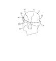
ここで図面を参照すると、図1,図1Aは、頭部5に装着された本発明のヘッドセットシステム10の一実施形態の斜視図である。一実施形態において、ヘッドセット10は、後方弾性部材30、前方弾性部材40および左右対称の半硬質および好適には硬質の部材50aを備えてよい外周フレーム(「ヘッドセット本体」)を備えるように構成されてよい。後方弾性部材30は、接続点8,16において左右対称の部材50aへ接続されてよい。前方部材40は、接続点14,18において左右対称の部材50aへ接続されるように構成されてよい。前方部材40は、前額領域12を包囲するように構成されてよい。後方弾性部材30は、後頭部領域11を包囲するように構成されてよい。中間の左右対称の半硬質部材50aは、耳16の後方および上方に配置されるように構成されてよい。
Referring now to the drawings, FIGS. 1 and 1A are perspective views of one embodiment of the
図2は、本発明のヘッドセットシステム10の一実施形態の斜視図である。ヘッドセット10は、弾性後方部材30、弾性前方部材40および硬質のおよび好適には半硬質の左右対称の部材50aを備えるように構成されてよい。後方部材30は、耳の後方に配置されるように構成されたサイズ調節機構32a,32bにより、中間の左右対称の部材50aへ接続されるように構成されてよい。前方部材40は、頭部の両側において耳の前方に配置されるように構成されたサイズ調節機構42a,42bにより、左右対称の中間部材50aへ接続されるように構成されてよい。
FIG. 2 is a perspective view of one embodiment of the
ヘッドセット10の様々な頭のサイズへの調節は、左右対称の前方調節機構32a,32bならびに後方の左右対称の調節機構42a,42bにより、行われ得る。弾性部材30,40を中間の左右対称の部材50aから離隔方向へ引くかまたは中間の左右対称の部材50aへ向かって押すと、ヘッドセット10のサイズ/外周が増加または減少する。特定の実施形態によれば、中間の左右対称の部材50aは、様々な頭の形に自己整合するように可撓性となるように構成されてよい。
Adjustments to the various head sizes of the
ヘッドセット10を様々な頭のサイズに合わせて調節する機構は、左右対称の前方調節機構32a,32bまたは左右対称の後方調節機構42a,42bのみを備えてよい。
The mechanism for adjusting the
一部の実施形態において、前方調節機構32a,32bならびに後方調節機構42a,42b双方により、頭部上のヘッドセットの対称な配置を維持しつつ、ヘッドセットの調節を向上させることができる。さらに、これにより、対応する耳の後ろ側の左右対称の部材50aの適切な配置を維持しつつ、ヘッドセットサイズの適切な調節をすることが可能になる。
In some embodiments, both the
後方部材30および前方部材40はそれぞれ、電極ベース(電極システムとも呼ばれる)60,70を備えるように構成されてよく、伸張状態になると、径方向力を電極ベースハウジング150に加えて頭皮へ移動させて、ヘッドセットから頭皮への望ましくない圧力を最小化しつつ、電極パッド56aと皮膚表面との間の電気接続を確保するように適合される。
The
中間の左右対称の部材50aは、電子回路52bを備えるように構成されてよい。電子回路52bは、導電性ワイヤ54により電池52aならびに電極ユニット60,70へ電気的に接続するように構成されてよい。
The middle
電子回路56bは、刺激回路、マイクロプロセッサ、充電回路およびユーザインターフェースを備えるように構成されてよい。 Electronic circuitry 56b may be configured to include stimulation circuitry, a microprocessor, charging circuitry, and a user interface.
刺激回路は、二相の充電バランス電気パルス、単相電気パルスおよび/または直流刺激を生成するように構成されてよい。 The stimulation circuit may be configured to generate biphasic charge balanced electrical pulses, single phase electrical pulses and / or direct current stimulation.
記載の好適な実施形態のさらなる特徴によれば、刺激回路は、電気刺激を強度範囲0〜80mA、0〜40mA、0〜20mまたは0〜15mA内で生成するように構成されてよい。 According to still further features in the described preferred embodiments the stimulation circuit may be configured to generate electrical stimulation within an intensity range of 0-80 mA, 0-40 mA, 0-20 m or 0-15 mA.
記載の好適な実施形態のさらなる特徴によれば、刺激回路は、刺激パルスを10〜600μsec、50〜500μsec、100〜500μsec、100〜450μsec、150〜400μsecまたは150〜450μsecの継続時間で生成するように構成されてよい。 According to still further features in the described preferred embodiments the stimulation circuit produces stimulation pulses for a duration of 10 to 600 μsec, 50 to 500 μsec, 100 to 500 μsec, 100 to 450 μsec, 150 to 400 μsec or 150 to 450 μsec. May be configured.
記載の好適な実施形態のさらなる特徴によれば、刺激回路は、刺激パルスを1〜500Hz、10〜300Hz、10〜250Hz、20〜180Hzまたは30〜180Hzの周波数で生成するように構成されてよい。 According to still further features in the described preferred embodiments the stimulation circuit may be configured to generate stimulation pulses at a frequency of 1 to 500 Hz, 10 to 300 Hz, 10 to 250 Hz, 20 to 180 Hz or 30 to 180 Hz. .
記載の好適な実施形態のさらなる特徴によれば、ヘッドセット10は、外部電子および刺激回路へ接続することにより電流を外部の刺激器具からヘッドセット電極へ移動させるように構成されてよい。ヘッドセット10は、身体の様々な領域に配置されてよい少なくとも1つの外部電極へ接続するように構成されてよい。ヘッドセット10は、信号をその基板センサー上から外部プロセッサへ移動させるために外部電子回路およびプロセッサへ接続するように構成されてよい。
According to still further features in the described preferred embodiments the
電池52aは、充電器を部材50a上に配置された充電ポート770へ差し込むことにより、再充電することができる。左右対称の部材50aは、使用者制御およびインターフェース750を備えるようにも構成されてよい。一部の実施形態において、左右対称の部材はどちらとも、ユーザインターフェース750を備えるように構成されてよい。一部の実施形態において、本発明のヘッドセット10の他の部分(例えば、前方部材40または後方部材30)は、ユーザインターフェース750を備えるように構成されてよい。
The
本発明の一部の実施形態において、ヘッドセット10の弾性部材30,40は、伸張モードにおいて、電極を保持していない領域においてヘッドセットから頭皮への望ましくない圧力を最小化しつつ電極パッド56aと皮膚表面との間の接触を確保するために径方向力を電極ベースハウジング150へ移動させるように構成されてよい。
In some embodiments of the present invention, the
図3は、ヘッドセット10の側面図である。一部の実施形態において、ヘッドセット10は、様々な特性(例えば、正確な配置、様々な頭のサイズに合わせた調節および電極取り付け)を維持しつつ頭部上のより高い位置に配置されるように構成されてよい。ヘッドセット10を頭部上のより高い位置に位置決めすることにより、他の神経および脳領域の刺激が可能になり、各種センサー(例えば、EEGセンサー)を頭部上のより高い位置に位置決めすることも可能になる。
FIG. 3 is a side view of the
本発明の別の態様によれば、ヘッドセット10は、より幅広の部材40,30へ接続するように適合されてよい左右対称の部材56aと共により幅広の弾性部材40,30を含むように構成されてよい。より幅広の部材40,30により、より大きな領域(例えば、様々な脳領域の刺激のための領域)を刺激するためにより大型の電極をヘッドセット10内に一体化することが可能になる。
According to another aspect of the present invention,
図4は、さらなる半硬質および好適には弾性の部材590を有するヘッドセット10の側面図である。部材590は、左右対称の部材56aへ垂直に接続されるように構成され、左右対称の部材56a間に配置され、かつ頭部の上部を包囲するように適合される。弾性部材590により、頭部上のより高い位置における電極およびセンサーの刺激および位置決めが可能になる。
FIG. 4 is a side view of the
図5は、後頭部領域上におけるヘッドセット10の安定性を増加させるために分岐型の後方弾性部材30を備えるように構成されたヘッドセット10の側面図である。
FIG. 5 is a side view of the
図6は、ヘッドセット10の斜視図であり、後方弾性部材30は電極を保持せず、その主要な機能または唯一の機能は、頭部上にヘッドセット10を安定させることである。
FIG. 6 is a perspective view of the
必要なとき、前方弾性部材40は電極を備えるように構成されてよく、後方部材30は電極を備える。
When required, the front
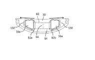
図7は、本発明の電極ベースまたはベース配置構成60の斜視図である。図7Aは、本発明の一実施形態による、配置構成60を収容する弾性部材30の斜視図である。
FIG. 7 is a perspective view of the electrode base or
図7,図7Aを参照すると、弾性部材30は、電極ベース60および導電性ワイヤ54を含むために少なくとも部分的に中空になるように構成され、かつ、弾性係数を低く維持しつつヘッドセットの安定した三次元構成の維持を支援するように構成される。弾性部材30は、(皮膚表面に対向する)内側上に少なくとも1つの開口部82を備えるように構成されてよい。電極ベース60は、少なくとも1つのハウジング150を含むように構成されてよい。一実施形態において、ハウジング150は、細長の可撓性の部材64へ接続されるように構成される。電極ベース60は、可撓性の接続バンド84が接続部位64において弾性部材30へ接続されるように、弾性部材30の内側に物理的に接続されるように構成されてよい。
Referring to FIGS. 7 and 7A, the
弾性部材30は、他の領域内のより高い弾性係数と比較して、電極ベースハウジング150の上方においてより低い弾性係数を有してよい。より低い係数が、開口部82に起因してまた他の領域よりも肉薄の開口部82に平行な領域において例えば部材30の外部表面の構成に起因して、ハウジング150の下面に平行な部材30の領域内において達成されてよい。よって、ヘッドセット10が装着されると、局所的な径方向力が部材30から電極ベースハウジング150上へ頭皮に向かって加えられる。これと対照的に、弾性部材30の他の領域は、より高い弾性係数を有するように構成されてよいため、余分な圧力が不要な箇所で回避されるよう、これらの領域における頭皮への径方向力が最小化される。また、より高い弾性係数を有するように構成された領域は、部材30およびヘッドセット10の安定した三次元構造の維持を支援することもでき、これにより、電極のより容易な装着および正確な配置が促進される。
The
図8,図8Aはそれぞれ、電極ベース60の斜視図および(図7Aに示す)弾性部材30の断面図である。電極ベース60への接続を可能にするために、弾性部材30は、突起96a,96bを備えるように構成されてよい。電極ベース60は、可撓性の接続バンド84内に穴部98a,98bを備えるように構成されてよい。電極ベース60および弾性部材30を物理的に接続するため、電極ベース60を弾性部材30に挿入して、突起96a,96bを穴部98a,98bへスナップ止めすることができる。物理的接続は、他の機構を備えてよい。例えば、可撓性部材68を接続部位64において可撓性部材30へ接着することができる。
8 and 8A are respectively a perspective view of the
図9は、弾性部材30の内側に接続された電極ベース60の断面図である。電極ベース60をヘッドセット部材30内に一体化することができ、可撓性の接続バンド84を接続部位64のみにおいて弾性部材30へ物理的に接続することができるため、ヘッドセットが装着されると、部材30を伸張させて電極ベースハウジング150および電極パッド56aに径方向力を加えて(電極システム60による制約無く)頭皮へ移動させることができる。この配置構成により、ヘッドセット部材30が伸張されたときに電極ベースハウジング150間の所定の距離を維持することも可能になる。
FIG. 9 is a cross-sectional view of the
図10は、一実施形態によるヘッドセット部材30の一部を示す。電極システム60(部分的に隠されている)を部材30内に一体化させる一方、電極ベースハウジング150および電極パッド56aのみが弾性部材30の開口部82a,82bを通じて突出する。可撓性の接続バンド84および接続部位64を点線によって示す。開口部82a,82bは、部材30が伸張したときに開口部82a,82bが横方向に延びることで部材30の伸張が制約を受けないようにするために、電極ベースハウジング150の中間縁を超えて延び得る。
FIG. 10 shows a portion of a
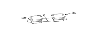
図11A〜図11Cは、隣接する電極ベースハウジング150間の距離を事前設定することが可能な本発明の電極ベース配置構成の斜視図である。図11A〜図11Cは、これらの電極ベースハウジングの3つの異なる事前設定された位置決め60A〜60Cを示す。図11Dは、図11A〜図11Cに示すこの調節可能な電極ベース配置構成を収容するための弾性部材の斜視図である。
11A-11C are perspective views of the electrode base arrangement of the present invention in which the distance between adjacent
記載の好適な実施形態の特定の特徴によれば、電極ベースハウジング150の位置を、特定の使用者の様々な形態的および人体変数に適合するように調節することができる。一実施形態によれば、電極ベースユニット60a,60b,60cは、その電極ベースハウジング150間の可変距離を有するように構成されてよい。これは、電極システムの穴部64および弾性部材30上の突起96a,96b(いずれも隠されている)により弾性部材30へ可逆的に接続されるように構成されてよい。記載の好適な実施形態の特定の特徴によれば、電極ベースユニット60a,60b,60cの接続は、他の接続機構によって行ってもよい。
According to particular features of the described preferred embodiments, the position of the
図12,図13は、記載の好適な実施形態のさらなる特徴による、電極ベースハウジング150の配置の調節のための機構を示す。
12 and 13 show a mechanism for adjusting the placement of the
図12は、一実施形態による弾性部材30の内部図であり、可撓性の接続バンド84は、部材30から伸長する突起96a,96b(いずれも隠されている)により部材30へ接続され、可撓性の接続バンド84中の穴部中へスナップ止めされる。可撓性の接続バンド84および弾性部材30の機械的接続は、他の機構(例えば、他のスナップコネクタまたは接着)により行われ得る。一実施形態によれば、可撓性の接続バンド84は、各穴部間の0.5〜5cmの範囲(より典型的には0.5〜3cm、0.5〜2cmまたは0.5〜1cmの範囲)内の距離において穴部98を含む。
FIG. 12 is an internal view of an
図13は、電極ベース60の一部の底面図である。一実施形態によれば、電極ベースハウジング150は、その下面から発生する突起92a,92bを含むように構成されてよい。突起92a,92bは、可撓性の接続バンド84内の穴部98のいずれか中へスナップ止めされるように構成される。電極ベースハウジング60の配置は、突起92a,92bを可撓性の接続バンド84中の他の穴部98中へスナップ止めすることにより、調節することができる。
FIG. 13 is a bottom view of a portion of the
図14は、電極ベース60内に配置された電極パッド56aの断面である。電極ベース60は、細長の可撓性の接続バンド84によりヘッドセットへ物理的に接続されるように構成されてよく、導電性ワイヤ158によりヘッドセット電気回路へ電気的に接続されてよい。電極ベース60は、「フロア」を包囲する隆起した外周壁を含む少なくとも1つの電極ベースハウジング150を含むように構成されてよく、これにより、少なくとも1つの導電性電極パッド56aを受容するように適合された空洞が生成される。特定の実施形態によれば、電極ベースハウジング150は好適には、可撓性の材料(例えば、シリコンまたは熱可塑性ポリウレタン樹脂(TPU))によって構成される。
FIG. 14 is a cross section of the
電極ベースハウジング150は、電極ベースハウジング150フロアの部分的に上方または電極ベースハウジング150フロア内に配置された導電性材料154を含むように構成されてよい。導電性層は、導電体158により電気回路へ電気的に接続されるように適合される。
The
導電性層154は、例えばステンレススチール、銅、真ちゅう、シリコン炭素、導電性銀塗料プリント、ステンレスメッシュまたは他の導電性要素などの材料を含むように構成されてよい。導電性層154が炭素製である場合、さらなる導電性塗料層がその下面上に印刷されてよい。このような導電性塗料層により、導電性層154の表面上の電流分布の均一性を向上させることができ、これにより、電極パッド56aの表面上の電流分布の均一性を向上させることができる。導電性層154は、電極ベース60の全体的可撓性に妥協を来さないよう、可撓性であることが好ましく、これにより、様々な頭の形との整列が確保される。特定の実施形態において、導電性層154は、その領域内に限定することができ、電極ベースハウジング150のフロア表面の一部のみを被覆するように構成されてよい。このような場合、導電性層154は可撓性でなくてもよく、当業者に公知の様々な導電性材料によって構成されてよい。導電性層154は、導電体(ケーブルまたはワイヤ)158へ電気的に接続されるように構成可能であるため、ヘッドセット電気回路へ電気的に接続可能である。
The
電極パッド56aは、(物理的かつ電気的に)電極ベースハウジング150へ解放可能な様態で接続されるように構成されてよい。電極パッド56aは、水または他の液体吸収材料(例えば、不織布、フェルトまたはスポンジ)のうち少なくとも一部を含んでよい。使用者は、使用前に電極パッド56aを水または他の液体に浸し得る。ハウジング150へ接続されると、電極パッド56aは、導電性層154と電気接触するように構成される。ヘッドセットが装着されると、パッド56aが皮膚表面へ付勢され、皮膚表面(頭皮を含む皮膚表面)と電気接触して、電流を皮膚表面へ移動させ得る。
The
電極パッド56aおよびヘッドセットと関連付けられた他の電極は、皮膚表面からの電流または他の生体信号(例えば、脳波(EEG))を受信(感知)し、これをヘッドセット回路を介してマイクロプロセッサを含む電子回路へ移動させるかまたはリモートユニットへ無線的に送信するように構成されてよい。
The
電極パッド56aは使い捨て型であってよく、使用者が簡便に交換することができる。
The
電極パッド56aは、パッド56aの中央領域よりも肉薄の端縁部156を含むように構成されてよい。端縁部156は、様々な製造プロセス(例えば、超音波溶接、RF溶接または熱圧縮)により構成されてよい。肉薄縁156をハウジング150中の対応する溝部152に挿入することにより、電極パッド56aをハウジング150へ可逆的に物理的に接続し、導電性層154へ電気的に接続することができる。
The
電極パッド56aは、ハウジング150と比較してより大型の領域を有するように構成されてよい。そのため、電極パッド56aをハウジング150中に押し込んで、ハウジング150へ可逆的に(物理的に電気的に)接続することができる。
The
電極ベースハウジング150は、電極パッド56aへ取り付けられた対応するコネクタへ物理的にかつ電気的に可逆的に接続されるように構成された導電性の機械スナップコネクタを備えるように構成されてよい。
The
本発明の多層電極パッド56aを含む電極ベース60および本発明の多層電極パッド56aを含まない電極ベース60の斜視図を図15A,図15Bに示す。図15C,図15Dは、多層電極パッド56aの断面図および底面図である。多層電極パッド56aは、水吸収層254と、好適には炭素フォイルで構成された可撓性の導電性層258とを備えてよい。これら2つの層は、取り付けてもよいし、あるいは直接取り付けてもよい。様々な製造プロセスが利用可能である(例えば、熱溶接、RF溶接、超音波溶接、接着または縫合)。液体吸収層254の縁における電流密度を低下させるために、導電性層258は、層254よりもより小さな面積または「設置面積」を有するように構成されてよい。その結果、(層258に対してより低い導電度を有する)層254の縁における電流密度が低下する。導電性層258は、導電性塗料の肉薄の導電性層255をさらに備えてよい。この導電性層255は、「メッシュ」パターンで印刷されてよく、層258の中央部位のみを被覆するように構成されてよい。導電性層255は好適には層258の下面上に印刷されてよく、多層電極パッド56aが電極ベースハウジング150へ取り付けられたときに電気的に接続されるよううに、電極ベースハウジング150の導電性層154に対向するように構成されてよい。導電性プリント層255は、層258よりも高い導電度を有するように構成されてよく、これにより、(層255を含まない)層258の縁における電流密度を低減しつつ、層258上の電流分散が向上する。
A perspective view of an
図16A,図17A,図18A,図19A,図20Aは、本発明の各種実施形態による、特定の電極パッド構造が電極ベースハウジングへ接続された電極ベースアセンブリの断面図である。図16B,図17B,図18B,図19B,図20Bは、図16A,図17A,図18A,図19A,図20Aに示す各電極パッドの断面図である。 16A, 17A, 18A, 19A, 20A are cross-sectional views of an electrode base assembly in which specific electrode pad structures are connected to an electrode base housing, according to various embodiments of the present invention. 16B, 17B, 18B, 19B, and 20B are cross-sectional views of the electrode pads shown in FIGS. 16A, 17A, 18A, 19A, and 20A.
ここで図16A,図16Bを参照すると、電極パッド56aは、液体吸収層254および「フック」(例えば、ベルクロ(登録商標))締結層252を備えてよい。双方の層を様々な製造プロセス(例えば、熱溶接、RF溶接、超音波溶接、接着または縫合)により取り付けることができる。一実施形態によれば、電極ベースハウジング150は、弾性ハウジング150の内周縁中の溝部中に配置された「ループ」(例えば、ベルクロ(登録商標))締結層256へ接続されるように構成されてよい。一実施形態によれば、電極パッド56aを解放可能に電極ベースハウジング150へ接続するため、使用者は、電極パッド56aをハウジング150内に配置することにより、電極パッド56aのフック層252およびループ層256を可逆的に取り付けることができ、これにより、導電性の層154と液体吸収層254との間の接触が確保される。
Referring now to Figures 16A, 16B, the
ここで図17A,図17Bを参照すると、電極パッド56aは、3つの層(すなわち、液体吸収層254、好適には可撓性の炭素層によって構成された可撓性の導電性層258、および電極パッド56aの下周縁の少なくとも一部へ接続された「フック」(例えば、ベルクロ(登録商標))締結層252)を備えてよい。これらの3つの層は、様々な製造プロセス(例えば、熱溶接、RF溶接、超音波溶接、接着または縫合)により取り付けることができる。一実施形態によれば、電極ベースハウジング150は、ハウジング150の内周縁内の溝部内に配置された「ループ」(例えば、ベルクロ(登録商標))締結層256へ接続されるように構成されてよい。一実施形態によれば、電極パッド56aを解放可能に電極ベースハウジング150へ接続するため、使用者は、電極パッド56aをハウジング150内に配置することにより、電極パッド56aのフック層252およびループ層256を可逆的に接続することができ、これにより、電極ベースハウジング150の導電性の層154と電極パッド56aの導電性の層258との間の接触を確保することができる。
Referring now to FIGS. 17A and 17B, the
導電性層258は、好適には電極ベースハウジング150の導電性層154に対向するように構成された下面上に印刷されてよい導電性塗料の層を備えるように構成されてよい。この導電性塗料層は、導電性の層258および液体吸収層254上の電流分布を向上させることができるため、皮膚と接触している皮膚表面における電流分布を向上させることができる。
The
電極パッド56aは、導電性の「オス」コネクタ(例えば、「オス」スナップコネクタ)を含むように構成されてよい。この「オス」コネクは、電極パッド56aへ物理的かつ電気的に接続されてよく、ヘッドセット電気回路へ電気的に接続され可能な電極ベースハウジング150中の対応する「メス」スナップコネクタへ可逆的に物理的かつ機械的に接続されてよい。
ここで図18A,図18Bを参照すると、電極パッド56aは、3つの層(すなわち、液体吸収層254、好適には可撓性の炭素層によって構成された可撓性の導電性層258、および接着ヒドロゲル層302)を備えてよい。液体吸収層254および可撓性の導電性層258は、様々な製造プロセス(例えば、熱溶接、RF溶接、超音波溶接、接着または縫合)によって取り付けることができる。接着ヒドロゲル層302は、ヒドロゲル層の接着特性により可撓性の導電性層258へ取り付けることができる。一実施形態によれば、電極パッド56aを解放可能に電極ベースハウジング150へ接続するため、使用者は、電極パッド56aをハウジング150内に配置することにより、電極パッド56aの接着ヒドロゲル層302および導電性層154を可逆的に接続することができ、電極ベースハウジング150および電極パッド56aの物理的および電気的接続を安定的に確保することができる。
Referring now to FIGS. 18A and 18B, the
ここで図19A,図19Bを参照すると、電極パッド56aは、液体吸収層254と、(例えば可撓性の炭素層で構成された)可撓性の導電性層258と、ハウジング150の導電性層154に対向するように構成された電極パッド56aの下周縁のうち少なくとも一部へ接続された両面接着層308とを含むように構成されてよい。液体吸収層254および可撓性の導電性層258は、様々な製造プロセス(例えば、熱溶接、RF溶接、超音波溶接、接着または縫合)により取り付けることができる。両面接着層308は、その接着特性により可撓性の導電性層258へ取り付けることができる。一実施形態によれば、電極パッド56aを解放可能に電極ベースハウジング150へ取り付けるため、使用者は、電極パッド56aをハウジング150内に配置することにより、電極パッド56aの両面接着層308およびハウジング150を可逆的に接続することができ、これにより、電極ベースハウジング150および電極パッド56aの物理的および電気接続を安定して確保することができる。
Referring now to FIGS. 19A and 19B, the
ここで図20A,図20Bを参照すると、電極パッド56aは、液体吸収層254と、好適には可撓性の炭素によって構成された可撓性の導電性層258とを含むように構成されてよい。液体吸収層254および可撓性の導電性層258は、様々な製造プロセス(例えば、熱溶接、RF溶接、超音波溶接、接着または縫合)により取り付けることができる。電極パッド56aは、液体吸収層254の中央領域よりも肉薄の端縁部312を備えてよい。より肉薄の縁312は、特定の製造プロセス(例えば、超音波溶接、RF溶接または熱圧縮)により作製することができる。使用者は、より肉薄の縁312がハウジング150中の対応する溝部310内へ「スナップ止め」されるまで電極パッド65aをハウジング150中へ押圧することにより、電極パッド56aを電極ベースハウジング150へ可逆的に接続することができる。この位置において、電極パッド56aの導電性層258および電極ベースハウジング150の導電性層154が取り付けられるため、ヘッドセットが装着されると、電流を導電性層154から導電性層258および液体吸収層254へ、およびその後皮膚表面へ移動させることができる。
Referring now to FIGS. 20A and 20B, the
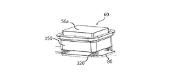
図21は、電極ベース60の斜視図である。記載の好適な実施形態の特定の特徴によれば、電極ベース60は、片側において可撓性の部材80へ、および他方側において電極ベースハウジング150へ物理的に接続されるように構成されてよい少なくとも1つのバネ機構320を含むように構成されてよい。バネ機構320は、電極ベースハウジング150について「自己調節」能力を提供するように構成されてよいため、ヘッドセットが装着されると、ヘッドセットから電極ベースハウジング150に加えられる力および頭部から加えられる抗力に合わせてバネ機構320が圧縮または拡張する。特定の実施形態において、バネ機構320は、金属またはプラスチックバネの代わりにまたは金属またはプラスチックバネに加えて弾性機構またはスポンジを備えてよい。
FIG. 21 is a perspective view of the
図21A,図21Bはそれぞれ、本発明の実施形態による電極パッド56aおよびベローズ型電極ベースハウジング150斜視図および断面図である。電極ベースハウジング150は、電極ベースハウジング150の下部へ物理的に接続されるかまたは電極ベースハウジング150の下部から延びるように構成されてよい可撓性のベローズキャリア321を含むように構成されてよい。可撓性のベローズキャリア321は、電極ベースハウジング150について「自己調節」能力を提供するように構成されてよいため、ヘッドセットが装着されると、ヘッドセットから電極ベースハウジング150に加えられる力および頭部から加えられる抗力に合わせてベローズキャリア321が圧縮または拡張する。
21A and 21B are a perspective view and a cross-sectional view, respectively, of an
図21Bを参照すると、可撓性のベローズキャリア321は、以下の寸法を有するように構成されてよい。
A−ベローズの各折り部の高さAは、1mm〜8mm、2mm〜6mmまたは2mm〜4mmの範囲内であってよい。
B−ベローズの各折り部の角度Bは、40°〜90°、50°〜80°または60°〜80°の範囲内であってよい。
C−ベローズの壁の厚さCは、0.3mm〜3mm、0.4mm〜2mmまたは0.5mm〜1.5mmの範囲内であってよい。
Referring to FIG. 21B, the
The height A of each fold of the A-bellows may be in the range of 1 mm to 8 mm, 2 mm to 6 mm or 2 mm to 4 mm.
The angle B of each fold of the B-bellows may be in the range of 40 ° to 90 °, 50 ° to 80 ° or 60 ° to 80 °.
The thickness C of the C-bellows wall may be in the range of 0.3 mm to 3 mm, 0.4 mm to 2 mm or 0.5 mm to 1.5 mm.
図21C,図21Dはそれぞれ、本発明の実施形態による、電極パッド56aと、円錐形状のベローズキャリア321を有する電極ベースハウジング150との斜視図および断面図である。円錐形状の可撓性のベローズキャリア321は、電極ベースハウジング150の下部へ物理的に接続されるかまたは電極ベースハウジング150の下部から延びるように構成されてよい。ベローズキャリア321は、電極ベースハウジング150について「自己調節」能力を提供するように構成することができるため、ヘッドセットが装着されると、ヘッドセットから電極ベースハウジング150に加えられる力および頭部から加えられる抗力に合わせてベローズキャリア321が圧縮または拡張し得る。ベローズキャリア321は、初期の弛緩状態高さの50%未満、40%未満、30%未満または20%未満まで可逆的に繰り返し圧潰するように構成されてよい。その結果、ヘッドセットおよび電極パッド56aを頭部に対する整列を大幅に向上させることが可能になる。
21C and 21D are perspective and cross-sectional views, respectively, of an
図22は、電極ベースハウジング150の斜視図である。一実施形態によれば、電極ベースハウジング150は、外周封止リム360を含むように構成されてよい。頭部の様々な領域を非侵襲的に刺激しようとしたときなどに髪を刺激した場合、髪に起因して表面電極と皮膚との間に高インピーダンス層が発生するため、問題が発生する。固体接着ヒドロゲルは、電気刺激電極中において用いられる最も一般的な導電性媒体である。しかし、ヒドロゲルの場合、髪が存在する場合にはヒドロゲルは髪層に浸透しにくいため、ヒドロゲルの使用はあまり適していない。他の導電性媒体(例えば、半液体導電性ゲル)は、各使用セッション後に髪およびデバイスの洗浄/清浄が必要になるため、使用者にとって利便的ではない場合がある。
FIG. 22 is a perspective view of the
対照的に、水道水は、髪層を通過することができ、残留物が無いため、浸透の点からより適している。さらに、導電性ゲルと対照的に、水道水は広く利用可能である。本発明者らは、必要な伝導度および実質的に均等な電流分布を確保するために、特に長期の治療セッション時には、実質的な水層を治療時に頭皮に対して維持する必要があり、脱水を回避する必要があることを発見した。電極脱水の回避は、髪の無い領域(例えば、前額)において必要になり得る。そのため、電極パッドおよび本発明の配置構成は典型的には、ヒドロゲルを含まないかまたは実質的に含まない。 In contrast, tap water is more suitable from the point of penetration because it can pass through the hair layer and there is no residue. Furthermore, in contrast to conductive gels, tap water is widely available. We need to maintain a substantial aqueous layer against the scalp at the time of treatment to ensure the required conductivity and substantially even current distribution, especially during long treatment sessions, I found it necessary to avoid. Avoiding electrode dehydration may be necessary in areas without hair (eg, forehead). As such, the electrode pads and configurations of the present invention are typically free or substantially free of hydrogels.
図23は、電極パッド56aが挿入された電極ベースハウジング150の断面図である。
FIG. 23 is a cross-sectional view of the
図24は、皮膚表面362へ付勢されている状態の、電極パッド56aが挿入された電極ベースハウジング150の断面図である。ハウジング150は、圧力が電極ベース60(図示せず)に対して封止リム360へ垂直方向に、および使用者の皮膚表面362へ加えられると、封止リム360が皮膚表面へ付勢されて封止リム360および使用者の皮膚表面362と雰囲気または外部環境との間に発生した空洞が実質的に封止されるように適合される。
FIG. 24 is a cross-sectional view of the
封止リム360は、可撓性の材料(例えば、TPUまたはシリコン)によって構成することができ、必要な封止効果が得られる一定レベルの圧力を頭皮に対して維持するのに十分な弾性係数を有するように構成されてよい。しかし、弾性係数が過度に高い場合、頭皮に対して過度な圧力がかかり得る。封止リム360は、様々な頭の形に合わせて自己整合できるよう、十分に可撓性であってよい。封止リム360は、電極を頭皮に対して所定位置に安定して配置することを支援するために高抵抗係数を有するように構成されてよい。また、封止リム360は、濡れた状態のパッドおよび封止された空間中に含まれる水の脱水を回避するように構成されてよいため、刺激セッションを有効かつ長期間にわたって行うことが可能になる。封止が不要な領域内に刺激電極が配置される場合、封止リム360は、電極ベースから取り外し可能に構成されてよい。
Sealing
ヘッドセットは、特定の皮膚表面および位置において適切な封止機能を確保するために、様々な外形を有する封止リムを含むように構成されてよい。必要な封止効果に到達するために、封止リム360は、水の存在下において膨張する材料を含むように構成されてよい。
The headset may be configured to include sealing rims with various contours to ensure proper sealing function at specific skin surfaces and locations. In order to reach the required sealing effect, the sealing
封止リム360を備えた電極ベースハウジング150は、電極パッドの脱水を回避するため、髪の無い領域(例えば、前額または身体の他の領域)に使用することが可能なように構成することができる。
The
封止リム360を備えた電極ベースハウジング150は、以下の寸法を含むように構成されてよい(図25参照)。
The
ハウジング150の可撓性の外周壁の内面は、径曲率を有する。リム360の内面とハウジング150の壁の内面の最も径方向に内方の点との間の径方向距離(A)は、1〜15mm、2mm〜10mmまたは2mm〜7mmの範囲内である。
The inner surface of the flexible outer peripheral wall of the
ハウジング150の可撓性の外周壁の外面は径曲率を有し、曲率の長さ(B)は、1mm〜15mm、2mm〜10mmまたは2mm〜8mmの範囲内である。
The outer surface of the flexible outer peripheral wall of the
図25Aは、本発明の電極ベースハウジング150の断面図である。電極ベースハウジング150は、封止リム360を有し、電極パッド56aを含む。電極パッドは、皮膚表面362へ付勢されている。ハウジング150は、圧力が電極ベース60(図示せず)に対して封止リム360へ垂直方向に使用者の皮膚表面362へ加えられると、封止リム360が皮膚表面へ付勢されて封止リム360および使用者の皮膚表面362と雰囲気または外部環境との間に発生した空洞が実質的に封止されるように適合されてよい。
FIG. 25A is a cross-sectional view of the
封止リム360は、可撓性材料(例えば、TPUまたはシリコン)製であってよく、必要な封止効果が得られる一定レベルの圧力を頭皮に対して維持するのに十分な弾性係数を有するように構成されてよい。しかし、弾性係数が過度に高い場合、頭皮に対して過度な圧力がかかり得る。
Sealing
特定の実施形態によれば、封止リム360の硬度レベルは20〜50ショアA、より好適には20〜40ショアA、最も好適には30〜40ショアAである。
According to a particular embodiment, the hardness level of the sealing
特定の実施形態によれば、封止リム360の(100%ひずみにおける)弾性係数(E)は0.4MPa〜3MPaであり、0.5MPa〜2MPaであり、または0.5MPa〜1.2MPaである。
According to a particular embodiment, the modulus of elasticity (E) (at 100% strain) of the sealing
封止リム360は、濡れた状態のパッドおよび封止された空間中に含まれる水の脱水を回避するように構成されてよいため、刺激セッションを有効かつ長期間にわたって行うことが可能になる。
The sealing
図25Bは、弛緩モードにおける25Aのハウジング150、封止リム360およびパッド56aの配置構成の断面図であり、壁ジオメトリが画定されている。封止リム360を含む電極ベースハウジング150は、以下の寸法を有するように構成されてよい(図25B参照)。
FIG. 25B is a cross-sectional view of the arrangement of the
封止リム壁厚(A)は、0.3mm〜3.0mm、0.4mm〜1.5mmまたは0.5mm〜1mmであってよい。
封止リム曲率長さ(B)は、1mm〜10mm、2mm〜8mmまたは3mm〜6mmであってよい。
封止リム曲率高さ(C)は、1mm〜10mm、2mm〜8mmまたは2mm〜4mmであってよい。
The sealing rim wall thickness (A) may be 0.3 mm to 3.0 mm, 0.4 mm to 1.5 mm or 0.5 mm to 1 mm.
The sealing rim curvature length (B) may be 1 mm to 10 mm, 2 mm to 8 mm or 3 mm to 6 mm.
The sealing rim curvature height (C) may be 1 mm to 10 mm, 2 mm to 8 mm or 2 mm to 4 mm.
図25Cは、電極パッド56aを含む本発明の電極ベースハウジング150の斜視図である。このハウジングは、電極パッド56aを外周方向に包囲する複数の近密に配置された封止フィンガー361を含む。ハウジング150は、圧力が電極ベース60(図示せず)に対して封止フィンガー361へ垂直方向に使用者の皮膚表面へ加えられると、封止フィンガー361が皮膚表面へ付勢されて、封止フィンガー361および使用者の皮膚表面と雰囲気または外部環境との間に発生した空洞を少なくとも部分的に封止するかまたは少なくとも実質的に封止するように適合されてよい。
FIG. 25C is a perspective view of the
封止フィンガー361は、可撓性の材料(例えば、TPUまたはシリコン)製であってよく、必要な封止効果が得られる一定レベルの圧力を頭皮に対して維持するのに十分な弾性係数を有するように構成されてよい。
特定の実施形態によれば、封止「フィンガー」361は、様々な表面/皮膚外形に合わせて自己整合するように構成される。流体の表面張力により、流体がフィンガー361間から流れることが回避され、これにより、流体がパッド56aの周囲に保持される。
According to certain embodiments, the sealing “fingers” 361 are configured to self-align to different surface / skin contours. The surface tension of the fluid prevents fluid from flowing between the
図25Dは、図25Cの配置構成の断面図である。 FIG. 25D is a cross-sectional view of the arrangement of FIG. 25C.
図25Eは、図25Cの配置構成の上面図である。封止フィンガー361を含む電極ベースハウジング150は、以下の寸法を含むように構成されてよい(図25D,図25E参照)。
FIG. 25E is a top view of the arrangement of FIG. 25C. The
封止フィンガー361の厚さ(A)は好適には0.3mm〜1.5mm、より好適には0.4mm〜1.2mm、最も好適には0.5mm〜1mmである。
The thickness (A) of the sealing
封止フィンガー361の角度(B)は好適には20°〜90°であり、より好適には40°〜80°、最も好適には60°〜80°である。
The angle (B) of the sealing
封止フィンガー361の幅(C)は好適には0.3mm〜3mm、より好適には0.4mm〜2.5mm、最も好適には0.5mm〜1.5mmである。
The width (C) of the sealing
封止フィンガー361間の隙間(D)は好適には0.1mm〜1.5mm、より好適には0.2mm〜0.1mm、最も好適には0.2mm〜0.8mmである。
The gap (D) between the sealing
図25Fは、本発明のハウジング150およびパッド56aの配置構成の断面図であり、ハウジング150の壁曲率363は、内壁曲率とパッド56aとの間に発生した空洞366中の余分な流体を捕獲および保存するように適合される。ヘッドセットが装着されると、パッド56aが頭部へ付勢されて、その余分な流体の一部を空洞366中へ解放させることができる。その後、空洞366中に含まれる流体はパッド56aによって再度吸収されてよく、皮膚表面へと解放される。
FIG. 25F is a cross-sectional view of the arrangement of the
図25Gは、本発明の一実施形態の電極ベースハウジング150が使用者の頭部5上に配置されてて頭部へ付勢されている様子の模式的斜視断面図である。図25Hは、電極ベースハウジング150および封止リム360が頭部5へ付勢されている様子の拡大図である。
FIG. 25G is a schematic perspective cross-sectional view showing how the
図26は、本発明の実施形態による、電極ベースハウジングの上方に配置される可撓性の櫛型の(「髪を梳く」)部材376の斜視図である。部材376は、電極ベースハウジング150の上方のヘッドセットへ物理的に接続されるように構成されてよく、また、いくつかの細長の硬質および好適には半硬質の部材またはまたは歯部378を含むように構成されてよい。
FIG. 26 is a perspective view of a flexible comb-shaped ("hair combing")
図27は、内部において可撓性の櫛型部材376がヘッドセット10の外周バンドの上方に突出した装着ヘッドセットの斜視後面図である。使用者がヘッドセット10を自身の頭部372に装着している間、細長部材378は、髪を含む領域(例えば、頭部の後ろ側または側部)において電極の上方に突出するように構成されてよい。櫛型部材376は、電極と皮膚との間に残る髪が最小になるように電極下の髪層を一時的に確実に押しのけつつヘッドセット10を簡単に装着することが可能なように構成されてよい。可撓性の櫛型部材376は、櫛のように機能するように構成されてよく、使用者がヘッドセット10を電極と共に上方に押して頭部372上の動作位置に配置している間に髪374の層を頭皮から分離させ、これにより、電極と皮膚との間の必要な導電度が確保される。
FIG. 27 is a perspective rear view of the mounting headset with the
記載の好適な実施形態の別の特徴によれば、部材376は、使用者の髪が短い場合に使用者が自分で取り外すことができるよう、ヘッドセット10から取り外し可能なように構成されてよい。
According to still further features in the described preferred embodiments the
本発明のヘッドセットは、様々な形状およびサイズの電極により頭部の様々な領域を刺激するように構成される。このヘッドセットは、前額領域を刺激するように構成された電極を備えてよい。 The headset of the present invention is configured to stimulate different regions of the head with electrodes of different shapes and sizes. The headset may include an electrode configured to stimulate the forehead area.
図28は、装着されたヘッドセット10の斜視前面図である。前額領域内の特定の神経枝を刺激するようにヘッドセットが構成され、前方電極110a,110bが適合される。これらの特定の神経枝は、滑車上神経120a,120bならびに眼窩上神経122a,122bを含み、これらはどちらも、三叉神経の表面分岐である。電極122a,122bは、所望の神経脱分極を最小の刺激強度および十分なレベルの知覚快適性と共に達成するよう、幅狭の細長外形を有するように構成されてよく、また、眉毛112aおよび112bの外形と少なくとも部分的に整列するように構成されてよい。電極110a,110bは、頭蓋骨の骨膜上に配置された痛覚神経繊維が活性化した場合に発生する不快感を最小化するよう、最小のサイズおよび特定の形状を有するように構成されてよい。電極110a,110bはまた、標的母集団中の広範囲の形態変数に関わらず標的神経への刺激が適切に確保されるようにも、構成されてよい。電極の寸法および特にその長さに影響を与え得るさらなる考慮事項として、使用者による装着時にヘッドセット10の回転配置に発生し得る予測される。そのため、これらの電極は好適には、このような回転逸脱時にも標的神経の上方の電極の少なくとも一部の配置を確保するために十分な長さを有するように構成されてよい。
FIG. 28 is a perspective front view of the attached
図29は、眼窩上領域の刺激のために構成することができる電極110aの実施形態を示す。電極110aは、生体適合性の導電性材料を含んでよい。この生体適合性の導電性材料は、皮膚表面に対向するように構成され、また、導電性接触表面へ取り付けられた電極支持部を含むように構成されてよい。この支持部は、導電性接触表面と電気的に接続されてよい少なくとも1つの導電性材料または要素を備えてよい。
FIG. 29 shows an embodiment of an
電極110aは、以下の寸法の導電性接触表面を有するように構成されてよい。
(i)長さが20mm〜55mm、25〜50mmまたは30〜45mmを有する長尺部(DL)。
(ii)長さが10mm〜30mm、10〜25または12〜20mmの短尺部(DN)。
凹状の外形Eは、凹面の対向する端部に配置された境界点GおよびFによって画定された凹面を有する。
The
(I) A long portion (D L ) having a length of 20 mm to 55 mm, 25 to 50 mm or 30 to 45 mm.
(Ii) Short sections (D N ) with a length of 10 mm to 30 mm, 10 to 25 or 12 to 20 mm.
The concave contour E has a concave surface defined by boundary points G and F arranged at opposite ends of the concave surface.
典型的には、A/Lは少なくとも0.5mmである。
Aは、点線Kおよび凹面によって境界を定められた領域である。
Lは、(境界点GおよびF間の)線Kの長さであり、(L)は少なくとも10mmであり、線が凹状の外形Eと反対側上の電極110aの周縁上の凹状の外形上の第1の点および第2の点間に配置され、第1の点において外形Eに対して垂直に整列され、この線は長さHを有する。
凹状の外形全体において、
![]()
Hmaxは、この全体におけるHの最大値であり、
Hminは、この全体におけるHの最小値である。
Typically, A / L is at least 0.5 mm.
A is the area bounded by the dotted line K and the concave surface.
L is the length of the line K (between the boundary points G and F), (L) is at least 10 mm, and the line has a concave outline E and a concave outline on the periphery of the
In the entire concave contour,
![]()
H max is the maximum value of H in this whole,
H min is the minimum value of H in this whole.
眼窩上領域を刺激するように構成された2つの電極間の距離は、5〜45mm、8〜35mmまたは8〜25mmの範囲内であってよい。他の神経(例えば、頬骨側頭神経または耳介側頭神経)を刺激するために、さらなる電極がヘッドセット上に配置されてよい。ヘッドセットは、後頭部領域を刺激するように構成された電極も備えてよい。 The distance between two electrodes configured to stimulate the supraorbital region may be in the range of 5-45 mm, 8-35 mm or 8-25 mm. Additional electrodes may be placed on the headset to stimulate other nerves, such as the zygo-temporal or auricle temporal nerves. The headset may also include electrodes configured to stimulate the occipital region.
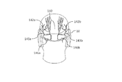
図30は、後頭部領域140における神経(例えば、左側大後頭神経142aおよび右側大後頭神経142b)を刺激するために、電極146a,146bがヘッドセット10の(後頭部に対向する)後ろ側に配置されるように構成された実施形態を示す。さらなる電極がヘッドセット中に配置されてよく、頭部領域中の他の神経(例えば、左側および右側の小後頭神経143a,143b)を刺激するように構成されてよい。
FIG. 30 shows that
大後頭神経の分岐142a,142bを刺激するため、これらの電極は、ほぼ後頭隆起の高さにおいて神経枝の上方に配置されるように構成されてよく、ここで、大後頭神経の分岐は、僧帽筋膜を貫通した後に表面となる。この解剖学的領域の下側が刺激されると、上頸筋が不利に収縮し得る一方、より高い領域が刺激されると、肩甲筋が不利に収縮し得、おまた頭蓋骨膜の侵害神経繊維に近接しているために痛みが生じ得る。そのため、電極を正確に配置した状態でかつ高レベルの知覚快適性と共に有効な刺激が保証される適切な寸法の電極を用いて、および近隣の筋肉へ刺激が溢れないように、確実に刺激を付与することが重要である。一部の実施形態において、電極146a,146bの寸法は好適には長さが20〜50mmであり、高さが8〜40mmであり、電極146a,146bは、後頭部正中線からの距離が5〜35mmの場所に配置されてよい。より典型的には、電極146a,146bの長さは25〜45mmの範囲内であってよく、高さが10〜25mmの範囲内であってよく、電極146a,146bは、後頭部正中線からの距離が8〜25mmの場所に配置されてよい。
In order to stimulate the branches of the large
図31は、一実施形態によれば本発明のヘッドセットの一部である左右対称の部材50aの側面斜視図である。記載の好適な実施形態の特定の特徴によれば、部材50aは硬質(好適には半硬質)となるように構成され、耳の後ろ側および上方に整列するように適合された曲線状部位408を有する。
Figure 31 is a side perspective view of a
図32は、頭部500上のヘッドセット10の斜視図である。ヘッドセット10は、医療専門知識の無い使用者が反復可能にかつ直感的に頭部上へ正確に配置することができるように構成されてよい。標的末梢神経および脳領域上に電極を正確に配置することは、所望の治療的恩恵の達成に欠かせない。頭部領域を刺激する場合、電極位置が少しでも逸脱すると頭蓋骨の骨膜上の刺激に起因して不快感およびさらには痛みの原因となり得るためまたは筋肉(例えば、前頭部、側頭筋、肩甲または上頸筋)の不要な運動収縮の原因となり得るため、正確な電極配置が特に重要である。
32 is a perspective view of the
左右対称の硬質のおよび好適には半硬質の部材50aは、使用者がヘッドセット10を実質的に正確にかつ反復可能な様態で自身の頭部500上に配置することが可能なように、構成されてよい。曲線状の左右対称の部材50aが両耳の後ろ側および上方に配置されると、ヘッドセット10の双方の外周の(回転)および長手方向配置が頭部500に対して決定される。
The symmetrical rigid and preferably
ヘッドセット10は、眉間正中線と共に鼻梁506の上方に整列するように構成されたその前方部位において凹部410を備えるように構成されてよい。ヘッドセット10の頭部500に対する適切な外周の(回転)および長手方向配置を鏡の利用の必要無く確保するために、使用者は、自身の親指を鼻梁506上に、および自身の(同じ手の)指のうち1本を凹部410上に配置して、ヘッドセット10の正確な配置を保証し得る。
The
ヘッドセット10の前方弾性部材40の外形は、眉毛502の解剖学的線および鼻梁506の上側領域と整列するように構成されてよく、これにより、使用者がヘッドセット10の前方弾性部材40を眉毛の上方と整列させると、ヘッドセットの回転および長手方向の配置方向が決定される。
The contour of the front
各特定の使用者に適合するために、左右対称の半硬質部材50aのヘッドセット10に相対する回転位置を個々に調節することができる。ヘッドセット10の配置方向を最適に調節するために、異なるサイズおよび形状の半硬質部材50aを選択することができる。ヘッドセットの前方長手方向配置方向を調節するために、様々な外形の前方弾性部材40を選択することができる。凹部410の位置を調節するか、または、ヘッドセット10およびその集積電極を必要に応じて非対称の整列のために構成することができる。
The rotational position of the symmetrical
ヘッドセット10の後方弾性部材30は、後頭部突起および項部線の上方に整列されてよい凹状の形状を有するように構成されてよく、これにより、ヘッドセット10の長手方向配置(より詳細には後方弾性部材の長手方向配置)が決定されてよい。
The back
図33は、「鼻梁」部材510を備えるヘッドセット10の斜視前面図である。「鼻梁」部材510は、弾性部材40の中央領域内に配置されるように構成されてよい。「鼻梁」部材510は硬質または半硬質であってよく、鼻の上部および鼻梁の両側において整列されるように適合された2つの細長部位を有してよい。「鼻梁」部材を鼻上に位置決めすることにより、使用者は、ヘッドセット10の回転および長手方向配置を決定することができる。
FIG. 33 is a perspective front view of a
「鼻梁」部材510は、部材40を重力に対抗して支持するように、さらに構成されてよい。「鼻梁」部材510は、ヘッドセット10から取り外し可能に構成されてよい。様々なサイズおよび形状の「鼻梁」部材510を個々の使用者に合わせて選択することができる。「鼻梁」部材510は、使用者の鼻に合わせて最適に調節できるように、使用者により手動調節されるように構成されてよい。
The "nasal bridge"
図34は、眼鏡520を有するヘッドセット10の斜視図である。眼鏡520は、前方弾性部材40へ接続されるように適合されてよい。一部の実施形態において、眼鏡520は、
・ヘッドセット10から可逆的かつ反復可能に取り外し可能であり、
・各種レンズ(例えば、視力向上のための光学レンズ、サングラス、または非光学的な透明レンズ)を含み、
・例えば片頭痛発生時の支援またはリラックスのために外部光を遮断するために用いられ得る濃色のレンズを含む、
ように構成されてよい。
FIG. 34 is a perspective view of a
Reversibly and repeatably removable from the
· Includes various lenses (eg, optical lenses for improving vision, sunglasses, or non-optically transparent lenses),
· Including a dark lens that can be used to block external light, for example to aid in migraine headaches or to relax
It may be configured as follows.
図35は、イヤフォン(例えば、左右対称のイヤフォン522)を有するヘッドセット10の斜視図である。一部の実施形態において、左右対称のイヤフォン522は、少なくとも半硬質の左右対称の部材50aへ電気的に接続されるように構成されてよい。
FIG. 35 is a perspective view of a
一部の実施形態において、イヤフォン522および左右対称の部材50aは、イヤフォン522を左右対称の部材50aから可逆的かつ反復可能に取り外することが可能となるように構成されてよい。
In some embodiments, the
一部の実施形態において、左右対称の部材50は、イヤフォン522を使用しないときにイヤフォン522を保管するために用いることが可能な内部空間および開口部を含むように適合されてよい。左右対称の部材50は、イヤフォン522を使用しないときにイヤフォン522を左右対称の部材50a内の保存空間内に引き込む機構を備えてよい。
In some embodiments, the symmetrical member 50 may be adapted to include an interior space and an opening that may be used to store the
図36は、ヘッドセット10をリモートコントロールまたはリモートコントロールハンドセット560、携帯電話570およびラップトップ/PC580と共に示す斜視図である。
FIG. 36 is a perspective
一部の実施形態において、ヘッドセット10は、リモートコントロール560と無線的に通信するように構成されてよい。リモートコントロール560は、使用者がコマンド(例えば、刺激開始または停止コマンド)または刺激強度を増加または低下させるためのコマンドをヘッドセット10へ送る際に用いられ得る。ヘッドセット10の状態に関し様々な視覚的および音声的指示を使用者へ提示することもできる。
In some embodiments,
ヘッドセット10は、携帯電話570と無線的に通信するように構成されてよい。携帯電話インターフェースを用いて、ヘッドセット10から無線的に送られる各種データ(例えば、ヘッドセット10の状態および使用ログについての視覚的および音声的指示)を提示することができる。
ヘッドセット10は、ラップトップ/PC580と無線的に通信するように構成されてよい。携帯電話インターフェースを用いて、ヘッドセット10から無線的に送られる各種データ(例えば、ヘッドセット10の状態および使用ログについての視覚的および音声的指示)を提示することができる。
The
ヘッドセット10およびリモートコントロール560、携帯電話570およびラップ
トップ580間の通信は、当業者に公知の様々な方法(例えば、Bluetooth(登
録商標)通信)により行うことができる。
本明細書中のおよび添付の特許請求の範囲において用いられるように、「モノリシック」という用語は、単一の少なくとも半硬質の統一体として構造的に機能することを意味する。
Communication between the
As used herein and in the appended claims, the term "monolithic" is meant to function structurally as a single at least semi-rigid unity.
本明細書中のおよび添付の特許請求の範囲において用いられるように、ヘッドセット、ヘッドセットフレームなどに対して「モノリシックに装着可能な」とは、ヘッドセット、ヘッドセットフレームなどを単一の少なくとも半硬質の全体として装着可能とする構造を指す。 As used herein and in the appended claims, "monolithically mountable" to a headset, headset frame, etc., refers to at least a single headset, headset frame, etc. It refers to a structure that can be installed as a semi-rigid whole.
本明細書中のおよび添付の特許請求の範囲において用いられるように、ヘッドセットまたはヘッドセットコンポーネントについての「動作モード」などの用語は、電気刺激が印加されている状態で適切な回転および長手方向の配置において使用者の頭部に適合されるヘッドセットまたはヘッドセットコンポーネントを指す。 As used herein and in the appended claims, terms such as "operation mode" for a headset or headset component are suitable for rotation and longitudinal with electrical stimulation applied. Refers to a headset or headset component that is fitted to the user's head in the placement of
本明細書中のおよび添付の特許請求の範囲において用いられるように、ヘッドセットまたはヘッドセットコンポーネントについての「装着モード」、「装着」などの用語は、電気刺激が印加されている状態で適切な回転および長手方向の配置において使用者の頭部に適合されるヘッドセットまたはヘッドセットコンポーネントを指す。 As used herein and in the appended claims, the terms "wear mode", "wear" and the like for a headset or headset component are suitable with electrical stimulation applied. Refers to a headset or headset component that is adapted to the user's head in rotational and longitudinal orientation.
本明細書中のおよび添付の特許請求の範囲において用いられるように、「一体」という用語は、単一の全体構造として機能する構造を指す。この用語は、特に可撓性の構造(例えば、電極パッド)に適用されてよい。 As used herein and in the appended claims, the term "integral" refers to a structure that functions as a single integral structure. This term may be applied to particularly flexible structures, such as electrode pads.
明確さのために別個の実施形態の文脈において記載される本発明の特定の特徴は、単一の実施形態と組み合わせてもよいことが理解される。逆に、簡潔さのために単一の実施形態の文脈において記載される本発明の様々な特徴を別個にまたは任意のさらなる組み合わせにより用いてもよい。同様に、1つ以上の特定の請求項に従属する請求項の内容は、概してその他の指定されていない請求項に従属する場合があり、あるいは両者間の任意の特定の明白な不適合を含まないその内容と組み合わせてもよい。 It is understood that certain features of the invention, which are, for clarity, described in the context of separate embodiments, may be combined with a single embodiment. Conversely, various features of the invention which are, for brevity, described in the context of a single embodiment, may also be employed separately or in any further combination. Similarly, the content of the claims dependent on one or more specific claims may generally be subordinate to other non-specified claims or do not include any specific apparent nonconformity between the two You may combine with the content.
本発明に関しその特定の実施形態と共に記載したが、当業者であれば多く代替例、改変例および変更例を想到することが明らかである。よって、本発明は、添付の特許請求の範囲の意図および広範な範囲内に包含される代替例、改変例および変更例全てを包含することが意図される。 While the invention has been described in conjunction with specific embodiments thereof, it is evident that many alternatives, modifications and variations will be apparent to those skilled in the art. Accordingly, the present invention is intended to embrace all such alternatives, modifications and variations as fall within the spirit and broad scope of the appended claims.
Claims (18)
(a)モノリシックフレームを画定する外周ヘッドセット本体であって、前記モノリシックフレームは、少なくとも1つの弾性部材(30、40)を備え、
前記モノリシックフレームが、前記使用者の前記頭部の外周に沿うように適合され、前記本体は、電源へ接続されるように適合された電気回路を収容し、
少なくとも1つの前記弾性部材が、前記ヘッドセット本体の外周の少なくとも一部上に配置され、かつ
少なくとも1つの前記弾性部材が、前記外周に沿って伸長されるように適合されている、外周ヘッドセット本体と、
(b)前記ヘッドセット本体へ機械的におよび半硬質にまたは硬質に接続され、かつ前記電気回路と電気的に関連付けられた少なくとも1つの電極ベースであって、前記電極ベースは、少なくとも1つの電極パッドを受容するように適合されている、電極ベースと、
を備え、
前記ヘッドセット本体および前記ベースは、前記使用者による装着時に前記電極パッドの電気刺激表面を前記皮膚表面へと方向付けるように適合され、
少なくとも1つの前記弾性部材は、前記装着時に前記弾性部材が径方向に前記電極ベースを前記皮膚表面へ付勢して前記電極パッドが前記皮膚表面と物理的かつ電気的に接触するように適合され、
少なくとも1つの前記弾性部材および前記電極ベースは、少なくとも1つの前記弾性部材の可変的な伸張に関して、接続部位のみを介して前記電極ベースと前記弾性部材が接続されることにより、前記電極ベースの前記フレームに対する外周位置を固定するように適合される、
ヘッドセット。 A headset for use in the delivery of electrical stimulation to the skin surface of the user's head, said headset comprising
(A) an outer peripheral headset body defining a monolithic frame, said monolithic frame comprising at least one elastic member (30, 40),
The monolithic frame is adapted to follow the periphery of the head of the user, the body contains an electrical circuit adapted to be connected to a power supply,
A perimeter headset, wherein at least one of the resilient members is disposed on at least a portion of a perimeter of the headset body, and at least one of the resilient members is adapted to extend along the perimeter. Body and
(B) at least one electrode base mechanically and semi-rigidly or rigidly connected to the headset body and electrically associated with the electrical circuit, the electrode base comprising at least one electrode An electrode base, adapted to receive a pad,
Equipped with
The headset body and the base are adapted to direct the electrical stimulation surface of the electrode pad to the skin surface when worn by the user.
The at least one resilient member is adapted such that the resilient member radially biases the electrode base to the skin surface such that the electrode pad is in physical and electrical contact with the skin surface when worn ,
At least one of the elastic member and the electrode base is connected to the electrode base and the elastic member only via a connection site in connection with variable extension of the at least one elastic member. Adapted to fix the circumferential position relative to the frame,
headset.
(i)前記外周の一部を形成し、前記長手方向の位置決めを決定するように前記使用者の耳の上方に沿うように適合された第1の細長要素と、
(ii)前記細長要素に対して略垂直に配置され、前記ヘッドセット本体の前記角度位置決めを決定するように前記耳の後方に沿うように適合された第2の要素と、
を有する、
請求項1〜5のいずれか1項に記載のヘッドセット。 The frame comprises a positioning system for angular and longitudinal positioning of the headset body, the positioning system comprising one or more semi-rigid or rigid side components, the side components Is
(I) a first elongated element forming part of the perimeter and adapted to conform above the user's ear to determine the longitudinal positioning;
(Ii) a second element disposed substantially perpendicular to the elongated element and adapted to follow the back of the ear to determine the angular positioning of the headset body;
Have
The headset according to any one of claims 1 to 5.
前記前方部が、前記ヘッドの前方部の周囲に沿うように適合し、かつ前記後方部が、前記ヘッドの後方部の周囲に沿うように適合する、
請求項7に記載のヘッドセット。 The frame comprises a semi-rigid or rigid side component and a first symmetrical sizing mechanism and a second symmetrical size adapted to adjust the circumference of the headset body An adjustment mechanism is further provided, wherein the first symmetrical size adjustment mechanism connects the side component to the front of the perimeter headset body, and the second symmetrical size adjustment mechanism comprises the side Connecting a component to the rear of the perimeter headset body;
The front portion conforms along a periphery of a front portion of the head, and the back portion conforms along a periphery of a rear portion of the head;
The headset according to claim 7.
(a)生体適合性の導電性接触表面を有する水吸収層であって、前記接触表面は、前記皮膚表面に並置されるように適合されている水吸収層と、
(b)前記水吸収層へ取り付けられた広範な第1の面を有する導電性層であって、前記導電性層は、少なくとも1つの導電性材料または要素を備え、前記導電性層は、前記第1の面から遠位にある広範な第2の面から電流を一体構造を形成する前記第1の面、前記水吸収層および前記導電性層を介して前記水吸収層へ移動させるように適合されている導電性層と、
を備える、請求項1〜請求項11のいずれか1項に記載のヘッドセット。 The at least one electrode pad is
(A) a water-absorbing layer having a biocompatible conductive contact surface, said contact surface being adapted to be juxtaposed to the skin surface;
(B) a conductive layer having a broad first surface attached to the water absorbing layer, the conductive layer comprising at least one conductive material or element, the conductive layer comprising A current is transferred from the broad second surface, which is distal from the first surface, to the water absorbing layer through the first surface forming the integral structure, the water absorbing layer and the conductive layer. A conductive layer being adapted,
The headset according to any one of claims 1 to 11, comprising:
(a)フロアと、前記フロアを包囲する可撓性の外周部材とを備えるハウジングであって、概して前記フロアの周縁の上方に延びる可撓性の外周壁を有し、前記壁は、外周リムにおいて終端し、前記フロアおよび前記可撓性の外周部材は、導電性電極パッドを受容するように適合された空洞を形成する、ハウジングと、
(b)前記フロアの少なくとも上方または内部に配置された導電性材料であって、導電体によって電気回路へ電気的に関連付けられるように適合され、前記パッドが挿入された場合、前記電極パッドと電気的に通信するように適合されている、導電性材料と、
を備え、
前記リムおよび前記可撓性の外周壁は、前記電極ベースへの圧力印加が前記リムに対して略垂直に使用者の皮膚表面に向かって付与されると、前記リムが前記皮膚表面へ付勢されて、前記空洞と雰囲気または外部環境との間が実質的に流体封止されるように適合されている導電性材料と、を備える、
請求項1〜請求項17のいずれか1項に記載のヘッドセット。 The electrode base is
(A) a housing comprising a floor and a flexible perimeter member surrounding the floor, the housing having a flexible perimeter wall generally extending above the perimeter of the floor, the wall having a perimeter rim A housing, terminating at the housing, the floor and the flexible perimeter forming a cavity adapted to receive a conductive electrode pad;
(B) a conductive material disposed at least above or within said floor, adapted to be electrically associated to an electrical circuit by a conductor, said pad being electrically inserted with said electrode pad Conductive material, which is adapted to communicate
Equipped with
The rim and the flexible outer peripheral wall bias the rim toward the skin surface when pressure application to the electrode base is applied substantially perpendicularly to the rim toward the skin surface of the user And a conductive material adapted to be substantially fluidly sealed between the cavity and the atmosphere or the external environment.
The headset according to any one of claims 1 to 17.
Priority Applications (1)
| Application Number | Priority Date | Filing Date | Title |
|---|---|---|---|
| JP2019025433A JP7051734B2 (en) | 2019-02-15 | 2019-02-15 | Headset for treatment and evaluation of medical conditions |
Applications Claiming Priority (1)
| Application Number | Priority Date | Filing Date | Title |
|---|---|---|---|
| JP2019025433A JP7051734B2 (en) | 2019-02-15 | 2019-02-15 | Headset for treatment and evaluation of medical conditions |
Related Parent Applications (1)
| Application Number | Title | Priority Date | Filing Date |
|---|---|---|---|
| JP2015562541A Division JP2016515404A (en) | 2014-03-15 | 2014-03-15 | Headset for treatment and evaluation of medical conditions |
Publications (2)
| Publication Number | Publication Date |
|---|---|
| JP2019088894A true JP2019088894A (en) | 2019-06-13 |
| JP7051734B2 JP7051734B2 (en) | 2022-04-11 |
Family
ID=66836987
Family Applications (1)
| Application Number | Title | Priority Date | Filing Date |
|---|---|---|---|
| JP2019025433A Active JP7051734B2 (en) | 2019-02-15 | 2019-02-15 | Headset for treatment and evaluation of medical conditions |
Country Status (1)
| Country | Link |
|---|---|
| JP (1) | JP7051734B2 (en) |
Cited By (3)
| Publication number | Priority date | Publication date | Assignee | Title |
|---|---|---|---|---|
| JP2020182721A (en) * | 2019-05-09 | 2020-11-12 | 株式会社三洋物産 | Game machine |
| KR102213309B1 (en) * | 2020-08-06 | 2021-02-08 | 주식회사 왓슨앤컴퍼니 | Transcranial electric stimulator |
| WO2023158082A1 (en) * | 2022-02-15 | 2023-08-24 | (주)메그노시스 | Wearable apparatus for biometric parameter measurement and/or transcranial electrical stimulation and operation method thereof |
Citations (5)
| Publication number | Priority date | Publication date | Assignee | Title |
|---|---|---|---|---|
| US3659614A (en) * | 1969-12-29 | 1972-05-02 | Bernard Jankelson | Adjustable headband carrying electrodes for electrically stimulating the facial and mandibular nerves |
| US6077237A (en) * | 1998-11-06 | 2000-06-20 | Adaboy, Inc. | Headset for vestibular stimulation in virtual environments |
| WO2012155117A1 (en) * | 2011-05-11 | 2012-11-15 | Covalin, Alejandro | Headache-treatment device with gel dispensing kit and method |
| US20130204315A1 (en) * | 2011-08-05 | 2013-08-08 | Ndi Medical, Llc | Systems for and methods of transcranial direct current electrical stimulation |
| WO2014141213A1 (en) * | 2013-03-15 | 2014-09-18 | Neurolief Ltd. | Headset for treatment and assessment of medical conditions |
-
2019
- 2019-02-15 JP JP2019025433A patent/JP7051734B2/en active Active
Patent Citations (5)
| Publication number | Priority date | Publication date | Assignee | Title |
|---|---|---|---|---|
| US3659614A (en) * | 1969-12-29 | 1972-05-02 | Bernard Jankelson | Adjustable headband carrying electrodes for electrically stimulating the facial and mandibular nerves |
| US6077237A (en) * | 1998-11-06 | 2000-06-20 | Adaboy, Inc. | Headset for vestibular stimulation in virtual environments |
| WO2012155117A1 (en) * | 2011-05-11 | 2012-11-15 | Covalin, Alejandro | Headache-treatment device with gel dispensing kit and method |
| US20130204315A1 (en) * | 2011-08-05 | 2013-08-08 | Ndi Medical, Llc | Systems for and methods of transcranial direct current electrical stimulation |
| WO2014141213A1 (en) * | 2013-03-15 | 2014-09-18 | Neurolief Ltd. | Headset for treatment and assessment of medical conditions |
Cited By (4)
| Publication number | Priority date | Publication date | Assignee | Title |
|---|---|---|---|---|
| JP2020182721A (en) * | 2019-05-09 | 2020-11-12 | 株式会社三洋物産 | Game machine |
| KR102213309B1 (en) * | 2020-08-06 | 2021-02-08 | 주식회사 왓슨앤컴퍼니 | Transcranial electric stimulator |
| WO2022030724A1 (en) * | 2020-08-06 | 2022-02-10 | 주식회사 왓슨앤컴퍼니 | Transcranial electrical stimulator |
| WO2023158082A1 (en) * | 2022-02-15 | 2023-08-24 | (주)메그노시스 | Wearable apparatus for biometric parameter measurement and/or transcranial electrical stimulation and operation method thereof |
Also Published As
| Publication number | Publication date |
|---|---|
| JP7051734B2 (en) | 2022-04-11 |
Similar Documents
| Publication | Publication Date | Title |
|---|---|---|
| US9872979B2 (en) | Headset for treatment and assessment of medical conditions | |
| US11986646B2 (en) | Resilient head mounted device for neurostimulation and sensing of body parameters | |
| US10426945B2 (en) | Methods and apparatuses for transdermal stimulation of the outer ear | |
| CN210811043U (en) | Wearable physiological activity sensing device and sensing system | |
| US11191949B2 (en) | System for electrical stimulation | |
| AU2015227382B2 (en) | Headset for treatment and assessment of medical conditions | |
| US20190223747A1 (en) | Wearable physiological activity sensor, sensing device, and sensing system | |
| JP2017528245A (en) | Headset for nerve stimulation and body parameter sensing | |
| US20230125579A1 (en) | Methods and apparatuses for transdermal stimulation of the outer ear | |
| JP7051734B2 (en) | Headset for treatment and evaluation of medical conditions | |
| US11571563B2 (en) | Electrically conductive ear tips | |
| WO2017125082A1 (en) | Wearable physiological activity sensing device and system | |
| KR102213309B1 (en) | Transcranial electric stimulator | |
| JP2004216069A (en) | Facial appliance | |
| KR101628299B1 (en) | Electrode pad | |
| KR101566781B1 (en) | Electrode pad | |
| KR20210105501A (en) | Beauty apparatus |
Legal Events
| Date | Code | Title | Description |
|---|---|---|---|
| A521 | Request for written amendment filed |
Free format text: JAPANESE INTERMEDIATE CODE: A523 Effective date: 20190314 |
|
| A621 | Written request for application examination |
Free format text: JAPANESE INTERMEDIATE CODE: A621 Effective date: 20190314 |
|
| A131 | Notification of reasons for refusal |
Free format text: JAPANESE INTERMEDIATE CODE: A131 Effective date: 20200225 |
|
| A601 | Written request for extension of time |
Free format text: JAPANESE INTERMEDIATE CODE: A601 Effective date: 20200522 |
|
| A601 | Written request for extension of time |
Free format text: JAPANESE INTERMEDIATE CODE: A601 Effective date: 20200722 |
|
| A521 | Request for written amendment filed |
Free format text: JAPANESE INTERMEDIATE CODE: A523 Effective date: 20200825 |
|
| A131 | Notification of reasons for refusal |
Free format text: JAPANESE INTERMEDIATE CODE: A131 Effective date: 20201222 |
|
| A601 | Written request for extension of time |
Free format text: JAPANESE INTERMEDIATE CODE: A601 Effective date: 20210319 |
|
| A521 | Request for written amendment filed |
Free format text: JAPANESE INTERMEDIATE CODE: A523 Effective date: 20210428 |
|
| A131 | Notification of reasons for refusal |
Free format text: JAPANESE INTERMEDIATE CODE: A131 Effective date: 20210810 |
|
| A601 | Written request for extension of time |
Free format text: JAPANESE INTERMEDIATE CODE: A601 Effective date: 20211108 |
|
| A601 | Written request for extension of time |
Free format text: JAPANESE INTERMEDIATE CODE: A601 Effective date: 20220106 |
|
| A521 | Request for written amendment filed |
Free format text: JAPANESE INTERMEDIATE CODE: A523 Effective date: 20220209 |
|
| TRDD | Decision of grant or rejection written | ||
| A01 | Written decision to grant a patent or to grant a registration (utility model) |
Free format text: JAPANESE INTERMEDIATE CODE: A01 Effective date: 20220315 |
|
| A61 | First payment of annual fees (during grant procedure) |
Free format text: JAPANESE INTERMEDIATE CODE: A61 Effective date: 20220330 |
|
| R150 | Certificate of patent or registration of utility model |
Ref document number: 7051734 Country of ref document: JP Free format text: JAPANESE INTERMEDIATE CODE: R150 |